
Introduction Summary of Program in FY97 - NASA two prior and lengthy field campaigns in Ft. Sumner...
13
I Final Report for Grant NAG5-5103: Development of EXITE3, Imaging Detectors and a Long Duration Balloon Gondola (February 12, 1997 - June 30, 2001) 1 Introduction In this Report we summarize the work conducted for the EXITE program under grant NAG5-5103. This grant supported the ongoing EXITE program at Harvard for the development of imaging hard x-ray detectors and telescopes over the 3 year period 1997-2000 with a one year extension to 2001 to transition to the next SR&T grant in this program. Work was conducted in three major parts: analysis of the EXITE2 balloon flight data (from our May 1997 flight); development of pixellated imaging Cd-Zn-Te detector arrays and readout systems for the proposed EXITE3 detector and telescope; and development of systems for a Long Duration Balloon (LDB) gondola. Progress on all three major aspects of this research is summarized for each of the years of this grant. 2 Summary of EXITE Program in FY97 Much has been achieved over this first year. In the following sections we provide a brief summary of major milestones and results, as well as work in progress. 2.1 EXITE2 Flight and Analysis After two prior and lengthy field campaigns in Ft. Sumner (May and September-October, 1996) during which no launch opportunities were possible for the new EXITE2 payload, we finally flew on May 7-8, 1997. We had a successful flight, with some 12 hours at float altitude, and observed a variety of targets: Crab, 4U0614+09, NGC 4151,3C273 and Cyg X-1. Payload Development The EXITE2 payload development and CZT detector development (for EXITE3) continued over the two prior launch attempts (May and September, 1996), under the preceeding grant, and then in the subsequent interval (October, 1996 - April, 1997). The following major tasks were accomplished: 0 additional development of flight software and flight computer and data recording system. 0 development of detector/telescope vs. star camera boresite fixture and analysis system. 0 additional development and sensitivity calibrations of off-axis CCD camera for below-the-balloon aspect determination. 0 development of both off-axis and on-axis CCD camera aspect software system. 0 further development of flight CZT/BGO detector and final optimization of the detector interface to flight computer system. 0 further development of EXITE2 calibration and analysis system. In addition, a major part of our effort during this period in Cambridge was the development of thick CZT detectors (see below). Balloon Flight: May, 1997 After some 7 launch attempts beginning April 20, the EXITE2 (and MIXE2, from our MSFC collabora- tors) payload was successfully launched on May 7, 1997, at 16:30UT. Performance of the 39m.cu.ft. balloon was excellent, and the payload reached a float altitude of 126,000 ft. at c. 20:OOUT May 7. Although several sounding ballons before launch indicated turnaround conditions, the high altitude winds carried the balloon NE at a mean speed of 20 knots so that the limit of telemetry range (and allowed impact area) was reached 1 https://ntrs.nasa.gov/search.jsp?R=20030056596 2018-07-02T20:00:56+00:00Z
Transcript of Introduction Summary of Program in FY97 - NASA two prior and lengthy field campaigns in Ft. Sumner...

I
Final Report for Grant NAG5-5103: Development of EXITE3, Imaging Detectors and a Long Dura t ion Balloon Gondola
(February 12, 1997 - June 30, 2001)
1 Introduction
In this Report we summarize the work conducted for the EXITE program under grant NAG5-5103. This grant supported the ongoing EXITE program at Harvard for the development of imaging hard x-ray detectors and telescopes over the 3 year period 1997-2000 with a one year extension to 2001 to transition to the next SR&T grant in this program. Work was conducted in three major parts: analysis of the EXITE2 balloon flight data (from our May 1997 flight); development of pixellated imaging Cd-Zn-Te detector arrays and readout systems for the proposed EXITE3 detector and telescope; and development of systems for a Long Duration Balloon (LDB) gondola. Progress on all three major aspects of this research is summarized for each of the years of this grant.
2 Summary of EXITE Program in FY97
Much has been achieved over this first year. In the following sections we provide a brief summary of major milestones and results, as well as work in progress.
2.1 E X I T E 2 Flight and Analysis
After two prior and lengthy field campaigns in Ft. Sumner (May and September-October, 1996) during which no launch opportunities were possible for the new EXITE2 payload, we finally flew on May 7-8, 1997. We had a successful flight, with some 12 hours at float altitude, and observed a variety of targets: Crab, 4U0614+09, NGC 4151,3C273 and Cyg X-1.
Payload Development The EXITE2 payload development and CZT detector development (for EXITE3) continued over the two
prior launch attempts (May and September, 1996), under the preceeding grant, and then in the subsequent interval (October, 1996 - April, 1997). The following major tasks were accomplished:
0 additional development of flight software and flight computer and data recording system.
0 development of detector/telescope vs. star camera boresite fixture and analysis system.
0 additional development and sensitivity calibrations of off-axis CCD camera for below-the-balloon aspect determination.
0 development of both off-axis and on-axis CCD camera aspect software system.
0 further development of flight CZT/BGO detector and final optimization of the detector interface to flight computer system.
0 further development of EXITE2 calibration and analysis system.
In addition, a major part of our effort during this period in Cambridge was the development of thick CZT detectors (see below).
Balloon Flight: May, 1997 After some 7 launch attempts beginning April 20, the EXITE2 (and MIXE2, from our MSFC collabora-
tors) payload was successfully launched on May 7, 1997, at 16:30UT. Performance of the 39m.cu.ft. balloon was excellent, and the payload reached a float altitude of 126,000 ft. at c. 20:OOUT May 7. Although several sounding ballons before launch indicated turnaround conditions, the high altitude winds carried the balloon N E at a mean speed of 20 knots so that the limit of telemetry range (and allowed impact area) was reached
1
https://ntrs.nasa.gov/search.jsp?R=20030056596 2018-07-02T20:00:56+00:00Z

-1 -
-2 1 0 1 2 AZ Degrees
Cyg X-l,93-127 keV
. . . . . . . . . . . ...... .: ...... 20h OOm . . . . . . . . . . . ....
:... ........ : :
. . . . . . . j ....... ...: . . . . . ..... -.. ..... . . . . . . . . . :
:: - . ! ......... .... : . ._ . . . _ .
-2 1 0 1 2 AZ Degrees
3C273,70-93 keV
.... . -.. ...: ....;
Figure 1: EXITE2 images from May 97 flight: a) Cyg X-1 and b) 3C373 field and GRS1227+025.
20h C4m
at c. 10:OOUT May 8, at which time the ballon was terminated just West of Oklahoma City. The 20 ft. high gondola landed at night on the banks of a 15 ft. wide creek (swollen from recent rains) and toppled in, so that the two exposed electronics racks for the EXITE2 detector-gondola interface and gondola pointing control were effectively ruined (as was the MSFC MIXE2 detector and electronics). Fortunately, the EXITE2 detector itself, the small CZT2 detector, and flight computer systems, were each in separate pressure vessels and survived with no apparent damage.
The first several hours of the flight were devoted to detector and gondola testing as several problems were encountered: the gondola azimuth pointing stability was initially poor, due to (it was later determined) overheating on an electronics board component for the azimuth gyro. Consequently the first target observed, the Crab, suffered from only moderate pointing stability, although a successful Crab observation and image was made. Also, as the aximuth gyro heating problem was understood, it was controlled by occasional shutdowns (during the solar-heated daytime portion of the flight) and stable pointing was achieved. The nighttime portion of the flight achieved relatively stable pointing, with drifts typically less than 5 arcmin per minute.
After the Crab observations, the flight achieved some 8 hours of good pointing on 4 science targets: the LMXB 4U0614+09, the QSO 3C273, the Seyfert NGC 4151, and finally the black hole candidate Cyg X-1. A high priority science target, GRS1915+105, was scheduled to be observed immediately after Cyg X1 but the higher than expected float winds did not allow this observation, or several others planned.
Analysis and Preliminary Results The daytime Crab data were reduced with aspect corrections for each second (given the initially large
pointing excursions) derived from the EXITE sunsensor. We also flew a GPS system for the first time and achieved excellent agreement in its azimuth readouts from those derived from the sunsensor. The GPS antennas and receiver (supplied by MSFC) were mounted on top of the gondola with plastic pipe booms separating the 4 antennas on baselines of c. 3.5m. This antenna separation enabled GPS azimuth determination each second with an rms uncertainty of about 4’ , or somewhat better than the sunsensor (with 6’ positional resolution each 2 sec readout).
Crab images and spectra were reported by Bloser et al (2002), and CygX-1 and 3C273 images from this 1997 flight are included with images from later EXITE2 flights in September 2000 and May 2001 as reported by Chou et a1 (2003a,b).
In Figures la and l b we show images for Cyg X-1 and the 3C273 observations. The 3C273 image is remarkable: it confirms the SIGMA discovery (Jourdain et a1 1992) of a separate
source, GRS1227+025, -15 ’ to the NE of 3C273. Although 3C273 itself is not detected significantly in our 60 min exposure, the flux upper limit (< 40 mCrab) is consistent with typical variability seen by SIGMA for 3C273 (Bassani et al. 1993). Our EXITE2 observation is the first hard x-ray image of the 3C273 region
2

since the SIGMA/GRANAT observations and confirms both the existence of the neighboring source and its likely identification with an Einstein-detected QSO at redshift z = 0.57 (Grindlay 1993). The implications are profound for HX surveys: this relatively bright ( ~ 1 0 0 mCrab in our image) QSO is ;z 100 x fainter in Einstein (and subsequent ROSAT) observations and so must be very heavily self-absorbed. Thus our EXITE2 observation provides a dramatic confirmation of the existence of previously unknown, bright, hard x-ray selected AGN, with their importance for understanding AGN and the x-ray background.
Nightime aspect for the Cyg X-1 observation was reduced with aspect corrections for each second derived from the EXITE2 on-axis star camera. Similar aspect corections were derived from the GPS system. We also successfully tested in flight the off-axis star camera (an integrating CCD camera) for which we also conducted day-time star sighting tests. We were able to record Sirius images, under pre-dusk conditions, but this (brightest star) case was still a significant test: Sirius was only some 50" from the Sun.
2.2
The considerable interest in CZT detectors, and yet the large thermal neutron cross section of Cd and subsequent y-ray (- 400 keV) decay, required that their background properties be measured in spaceflight conditions. We carried out the first flight background measurements of the background spectrum for CZT with a thick BGO anti-coincidence shield to veto the induced background events. In order to simultaneously measure the (approximate) thermal neutron flux in flight, we also flew an experiment to measure neutron flux. Measurement of CZT Background with BGO Anti-Coincidence
The EXITE2 flight payload included a small (1 cm2) single-element CZT detector and BGO shield. The data from this detector system was read into the flight computer and recording system with priority so that essentially all (-88%) of this low-rate data (-1 ct/sec) was recorded both on board and telemetered to the ground. The anti-coincidence BGO shield system worked well and allowed the first measurement of active anti-coincidence of CZT with a planar BGO shield in the close proximity as would be used in an imaging CZT array detector. Results were presented in Bloser et a1 (1998a).
The spectrum showed a significant reduction (factor of 7 at 100 keV) in background due to rejection by the BGO shield, thus showing CZT can be used as a low background detector provided proper shielding is included. The corresponding background spectrum measured in the EXITE2 phoswich detector is only about a factor of 1.5 lower: B - 6 x ~ O - ~ cts/cm2-sec at 100 keV, indicating that at 100 keV the particle induced backgrounds in these differently shielded detectors was similar (at this energy the differing diffuse backgrounds in the very different fields of view should not be significant).
Measurement of Neutron Background We also carried out an experiment on our balloon flight to measure, or at least constrain, the neutron
background at balloon altitude. This was flown on top of the EXITE gondola as a passive experiment which consisted of two sets of thin gold foils, one effectively exposed to space and the other shielded by Pb with the approximate grammage (3mm of Pb overburden) of the proposed EXIST collimator, in order to measure the in-flight neutron background. This is important in order to more completely understand the total and non-vetoed background spectrum measured in the CZT detector since it is expected to have a significant background produced by the very large neutron cross section for Cd (in the CZT). The neutron background sustained in flight was measured by the expected reaction (at float),
Flight Test of CZT and BGO Shield: Backgrounds in CZT
Au-197(n,gamma)Au-198( ,e)Hg-198 on the gold foils of atmospheric neutrons which have thermalized in the surrounding detector (and gondola) mass and for which the neutron capture cross section has a strong resonance at 5 eV, with some contribution from lower energies. The latter part of the reaction has a decay time of 2.7d and produces a gamma-ray of 412keV 96% of the time. By rushing the gold foils off to a Ge spectrometer and measuring the 412 keV line immediately (within say 24 hours) after the flight in a low background chamber, we were able to infer the neutron flux and provide a check on the rather poorly determined atmospheric neutron flux otherwise only predicted by Armstrong (1973).
We conducted this experiment in collaboration with Larry Varnell (JPL), who did the low background counting of the foils (Fedexed on the day of recovery of the payload from Oklahoma City to Pasadena) in
3
his Ge spectrometer a t JPL. Analysis showed that the ambient neutron spectrum at float was indeed within a factor of -1.5 of the very uncertain value prediced by Armstrong.
2.3
Over this year we also made progress in setting up and carrying out our program to develop CZT imaging array detectors using pixellated readouts on moderately thick (2-5 mm) substrates. Our program was directed towards development of pixellated CZT arrays that could be modularized into a very large area detector as needed for the proposed EXIST all-sky survey mission with sensitivity up to 600 keV. We formed collaborations with two local (Boston) area companies, Radiation Monitoring Devices (RMD) (Watertown, MA) and Spire Corporation (Bedford, MA), to undertake a collaborative program of CZT detector and imager development. In addition, we initiated and obtained successful results from a third collaboration, with the IDE Corp. (Norway), for the development of the ASIC readout system for imaging CZT detectors.
Development of High Energy CZT Imagers
Prototype Imaging CZT-MSM Array: Collaboration with RMD With RMD, we developed a prototype conventional CZT (HPB) detector array with metal (gold) contacts
for a metal-semiconductor (CZT)-metal (MSM) configuration. RMD fabricated this detector for us with standard so-called detector grade (i.e. not superior spectroscopy grade) CZT grown by eV Products by the (now) conventional High Pressure Bridgman (HPB) technique. The detector was 10 x 10 x 5 mm with 1.5mm (square) pixels on a 1.7mm pitch in a 4 x 4 array.
Results for the imaging and spectroscopic performance were excellent and are reported in the paper (Bloser et a1 1997) presented to the Materials Research Society (MRS) meeting. A more detailed summary of this work as well as comparison with the PIN detector array was presented at the SPIE by Narita et a1 (1998).
Prototype Imaging CZT-PIN Array: Collaboration with Spire Spire had initiated a program to develop CZT detectors with a novel PIN electrode configuration which
permits much lower leakage currents for a given resistivity CZT material, allowing lower resistivity crystals of lower cost and increased availability to be used. In particular, CZT grown by the so-called Vertical Bridgman technique developed for normal CdTe but intrinsically of lower resistivity than normal High Pressure Bridgman CZT, can be used which should cut detector costs dramatically. We obtained the first results for the imaging and spectral performance of a PIN electrode CZT imaging array: a 4 x 4 pixel detector fabricated on a 2mm thick CZT crystal with the same lOmm crystal size and 1.5mm pixel size as used for the RMD detector. Because this detector is not as thick as the 5mm thick RMD detector, it is not as effectively in the small pixel regime (Barret et a1 1995) and would be expected to show significantly more charge trapping and low energy tailing in its spectra. However its spectra are nearly comparable to the RMD device so that tests with a thick (5mm) PIN array as planned for the coming year will be particularly interesting. These results were reported by us in Narita et al (1998).
Prototype ASICs: Collaboration with IDE We also initiated a close collaboration and working relationship with the IDE Corp. of Oslo, Norway,
who are a leading source of Application Specific Integrated Circuit (ASIC) designs and custom devices. Their chief designer, Einar Nygard, visited us at Harvard and discussed in detail their current ASIC designs. We have used the IDE VA-1 ASIC on a test board fixture, supplied by IDE with output line drivers, to readout our RMD and Spire detectors in their modular chip-carrier package design. This was accomplished by our designing and fabricating a custom interface board to couple the CZT-chip carrier t o the ASIC inputs. Although this test interface board was done with discrete components and wire connections (rather than a custom PC board), we were able to achieve respectable low noise levels of -400 e- for the entire system. A brief summary is provided in Bloser et a1 (1997) and a more detailed description is given in Narita et a1 (1998).
4

3 Summary of EXITE Program in FY98
Significant progress was made over this year in each of the three major program areas: EXITE2 analysis, CZT detector and thus EXITE3 development, and LDB gondola development. Each is described briefly here.
3.1 EXITEZ Analysis
3.1.1 Detector Performance
Over this past year, we have concentrated on completing our analysis of the performance of the EXITE2 detector on its first science flight launched May 7, 1997, from Ft. Sumner. This has largely been completed, and initial results were reported in our paper presented at the November 1998 IEEE (Chou et a1 1999a). The key results are:
Background spectrum: Background rejection was generally excellent in the energy range -40-300 keV, with values comparable to the best PSD rejection achieved in non-imaging phoswich detectors. At higher energies PMT saturation effects must be corrected; whereas at lower energies (-20-40 keV) we now finally understand the large low energy peak first seen in our EXITE2 engineering flight (cf. Lum et a1 1994) and now also reported in Chou et a1 (1999a) as being due to glow from long time constant light components (with decay times -40 and 300 psec) in the CsI(Na) component of the phoswich detector. Complete results of simulations which are now able to predict and account for this glow peak are reported in Chou (2001). These simulations also describe the light distribution in the EXITE2 phoswich and the component of glow events that can be rejected (by light distribution) vs. glow components, as well as normal photon events in the CsI, that cannot be distinguished from NaI events (i.e. depth discrimination is not possible in this phoswich).
Glow distortions: The same long-time constant component of the scintillation light from the CsI, the glow component producing the low energy background peak, also produces a subtle distortion in position resolution and thus imaging sensitivity in an imaging phoswich detector. This results from the finite variation of gain across the detector, with (in any scintillator) lower light collection efficiency near the edge of the detector giving rise to lower effective gain. Since then glow components become a larger fraction of the detected light distribution, the spatial resolution and thus imaging sensitivity in the coded aperture telescope degrades out towards the detector edge. Complete discussion of this new effect, which will constrain any imaging scintillator, is given in Chou et a1 (1999a).
Background and spectral response: We developed a complete modeling package for the detector and telescope background using the GEANT code (from CERN); this greatly extends the background studies first done for EXITE2 by Lum et a1 (1994). This GEANT modeling, now essentially complete, was extended to produce the final spectral response tables for EXITE2, which will allow the spectral analysis of the sources observed (e.g. Cyg X-1; NGC 4151 and 3C273) and comparisons with the Crab spectrum observed on the flight. Results are given in Bloser et a1 (2002) and were used for rapid analayis of spectra on the next science flight in September 2000.
3.1.2 Imaging Analysis
We carried out extensive analysis of the EXITE2 imaging sensitivity as a function of the detector imaging area used (i.e. the radial dependence of imaging sensitivity) and discovered the second-order glow effect mentioned above which degrades imaging sensitivity with the (inevitable) decrease in detector gain towards the detector edge (Chou et al 1999a). The analysis of EXITE2 images of Cyg X-1 and the Crab and comparisons with ground calibration data have also enabled us to measure and characterize the effects of (small) spatial distortions in the detector. Finally, we developed new statistical techniques for measuring the detector flatness and effective noise, as well as compensating for spatial background variations by flatfielding. Results are summarized in Chou (2001).
5
3.1.3
The EXITE2 flight provided the first test of our PC-based flight computer and data recording system. This single-board computer (SBC) 486-PC and DSP computer data interface to the detector and gondola systems generally worked well in flight although a number of anomalies were encountered. These have now been understood as arising from several subtle errors in the onboard software which have now been fixed. This system provided the basis for recording data and compression modes for both the EXITE2 and also the prototype EXITE3 (test CZT imaging array experiment; see below). It also later served (2000 and 2001 flights) as the general computer interface to the re-built (MSFC) gondola and command and data-handling system, all linked by a local area network to the SBC via a local interface computer (PC-104/486).
Flight Computer and Data Recording
3.1.4 Detector Electronics Re-build
Given the complete loss of our gondola electronics rack (which controlled gondola pointing and data/command electronics) as well as detector electronics interface rack (which controlled detector modes and generated de- tector housekeeping data) in the water landing after our May 1997 flight, we carried out a major program over this project year to re-design and build these systems. The design was completed and board fabrication nearly done.
3.2 Development of LDB Gondola
In collaboration with MSFC (B. Ramsey and J. Apple), we began re-building the EXITE gondola pointing and command/data handling electronics (which, again, were destroyed on our water landing in May 1997). MSFC carried out the bulk of the electronics re-build, but we supplied the major mechanical systems (azimuth system and reaction wheel; elevation flange; mask tower and gondola frame). The new control electronics (as well as new EXITE2-3 electronics) were designed to accomodate or be readily adapted to long duration balloon (LDB) flight conditions.
A significant effort over this year was to study the requirements for a daytime star tracker so that au- tonomous daytime pointing control can be maintained on a LDB mission. Our previous EXITE1-2 gondola inertial pointing system and daytime aspect (sun tracker) systems (Grindlay et a1 1990) required occasional manual updates for correcting gyro drifts and maintaining arcmin pointing. The new EXITE/MSFC gondola will enable closed-loop pointing with feedback from the star camera system to correct gyro drifts automat- ically. The daytime star tracker requirements are being developed from our recently completed analysis of the prototype camera we successfully flew on our May 1997 flight: a CCD (c. 5122 pixels; each -3Oarcsec square) equipped with a sunshade baffle and red-IR filter (Wratten 89B; passband longward of -700nm, with CCD cutoff at -950nm). We successfully imaged the bright star Sirius during the daytime flight at an angle of -65" from the Sun and used this to derive the measured sky brightness a t balloon altitude. The results are within a factor of 2 of predictions based on an Air Force code (MODTRAN) and suggest that we can indeed use a CCD with I-band filter for the daytime tracker, as described below.
3.3 EXITE3 Development
Our major new instrumentation effort under the EXITE program continues to be the development of imaging Cd-Zn-Te (CZT) array detectors. We are investigating pixellated arrays (rather than strip detectors) given their likely superior energy resolution and noise characteristics. Our primary objective is to optimize both energy resolution and high energy response (up to -600 keV) for imaging detectors and to develop an optimized readout (ASIC) and shielding system for tiling detectors into a very large area array as needed for a high sensitivity hard x-ray imaging survey mission such as EXIST (Grindlay et a1 1995) or our proposed ULDB concept mission, EXIST-LITE (Grindlay et a1 1998). Our work over this project year continued our work begun last year in three areas: background studies; development of PIN-contact CZT imagers; and (most recently) testing and evaluation of a promising new source of CZT from the Imarad Co. (Israel).
6

3.3.1
Our May 1997 flight included a non-imaging CZT detector (10mm square; 2mm thick) mounted above a thick (75mm diameter and thickness) BGO anti-coincidence shield. The shield was designed to both shield the CZT from atmospheric gammas entering from the rear as well as provide a veto for internally generated background or events which Compton scatter in the CZT into the rear hemisphere. Analysis of the flight data and a GEANT simulation of the background was completed and reported by Bloser et a1 (1998a). The CZT detector was shielded from the sides and top by 2mm of P b (and -1.5mm Sn/Cu graded shield), with the top shield to simulate the overburden affects of a passive collimator with wide field as proposed originally for the survey mission concept EXIST (Grindlay et a1 1995). The measured background flux at 100 keV was reduced by the rear shield veto by a factor of -6 to a value of - 9 x cts/cm-2-sec, or about a factor of (only) 2 above the flux measured in the narrow field (4.5” ) NaI/CsI phoswich detector of EXITE2 on the flight. Although the spectral shape and flux agreed within a factor of 2 with the GEANT predictions for the shield configuration, deviations at both low (< 50 keV) and high (2 200 keV) energies were found (Bloser et a1 1998a) and would be further investigated with the flight test of a shielded imaging detector planned for the coming year.
Analysis of Flight Test of Backgrounds in C Z T
3.3.2 Development of C Z T / P I N Imagers
Over this past year, we continued our program in collaboration with the Spire Corp. to develop CZT pixellated array detectors using blocking contacts for the anode pixels and cathode electrode. These detectors have incorporated PN diode junctions into their contacts: the anode pixels are N-type material (CdS), whereas the solid cathode plane on the opposite face of the CZT crystal is P-type material (either ZnTe or simply gold). The detector is reverse-biased so that the resulting leakage current across the detector (the Intrinsic CZT semi-conductor) is reduced since the device then acts as a P-I-N or PIN diode, allowing for lower noise and thus enhanced energy resolution for a given resistivity detector.
Testing PIN arrays: We have characterized two such detectors fabricated by Spire which incorporated the conventional high resisitivity CZT produced by eV Products using the so-called High Pressue Bridgman (HPB) technique. Both detectors had 4 x 4 pixel (each 1.5mm square and spaced with 1.7mm pitch) array readouts surrounded by a single guard ring, and were thus identical in their pixel geometry to the conventional (gold anode pixel) CZT detector (metal-semiconductor-metal, or MSM) originally fabricated for us by RMD Corp. and characterized by Bloser et a1 (1998b). The two PIN imagers were each the same 10 x lOmm area as the MSM detector, with one having thickness 5mm (identical to the MSM device) and the other 2mm thickness. Both the MSM and PIN detectors provided the first direct demonstration of the operation of the “small pixel effect” (whereby energy resolution is improved by collecting charge on pixels with dimension small compared to detector thickness) for relatively large dimension (1.5mm) pixels.
Both prototype PIN imagers were tested with the same 16-channel prototype ASIC (IDE-VA1 test board) containing preamp and shaper and output line drivers as had been used for the MSM detector. Each of the 3 detectors (the two PIN devices and the original MSM array) were mounted in a chip carrier so that both PIN detectors could be tested, and compared with the MSM device, through the same ASIC readout. An improved (lower noise) interface board, containing the chip carrier socket and bias resistors and de-coupling capacitors, was fabricated (using a PC board layout) and used for final testing. Results are reported in Narita et a1 (1998). In general, the PIN contacts reduced leakage current by factors of -3.
Designing Guard Ring Arrays: Our tests with PIN contact CZT imagers also included experiments to bias the single surrounding guard ring at modest negative potential (10-3Ov) with respect to the anode pixels so that it can act as a steering electrode to enhance charge collection, and thus energy resolution, on the anode. Initial results are also given in Narita et a1 (1998). Prompted by this we carried out simulations of the electric field (using a commercial electrostatics code) and approximate charge transport in CZT for various guard ring geometries. Tradeoffs between likely guard ring bias (in turn dependent on surface leakage currents, which may themselves be reduced by the PIN contacts) and pixel vs. guard ring dimensions were studied, and an optimum (approximate) design was derived employing an interlaced guard ring and pixel geometry.
7

3.3.3 Testing of Imarad CZT
In September 1998, we became aware (along with the CZT community) of a damatic new development in CZT fabrication and array fabrication: the Imarad Imaging Systems (Rehovot, Israel) had developed a Horizontal Bridgman (HB) growth technique to produce high purity, but relatively lower resisitivity (and thus higher leakage current) CZT. They also produced pixellated array detectors with their material and had begun developing a medical x-ray imaging camera for commercial use. Most importantly, they developed a new method of doping the CZT crystal during the growth process (they have not published details) which somehow allows the holes (charge carriers) to be effectively annihilated so that the problem of hole-trapping and thus incomplete charge collection of conventional CZT is largely eliminated. This detector operation is not well understood, and our testing of these detectors was aimed in part at elucidating the relative importance of this claimed hole-annihilation vs. conventional small pixel effect operation as the explanation for the superior energy resolution achieved.
We began a program to test and evaluate Imarad CZT and explore its use for a large area imaging detector. We initiated this in collaboration with Imarad, who kindly sent us sample detectors, to explore three principal objectives: 1) to verify and confirm the claimed performance and lack of hole trapping of the pixellated detector sample provided by Imarad; 2) to carry out materials uniformity tests of the bare CZT crystals to measure their uniformity and internal field distribution when fabricated as PIN detectors; and 3) to fabricate prototype PIN detectors using this material to further reduce its leakage current.
4 Summary of EXITE Program in FY99 (and partial FYOO N.C. Extension)
In the final year of this grant period, the principal effort was spent on development of the CZT imagers to be used eventually for an EXITE3 detector system. Whereas the 1997 balloon flight in the first year of this grant cycle had included a flight test of our first generation CZT detector (CZTl), a non-imaging lOmm x lOmm CZT crystal with thick rear BGO shield, the major effort in FY99 was the design and development of an imaging CZT detector (CZT2) with passive/plastic shields for spatially resolved background measurements from balloon altitude. Two flights of CZT2 were finally conducted at the very end of this grant period: in September, 2000, and again in May, 2001. Both are briefly discussed below, together with the final results from EXITE2.
We first describe the development work carried out in FY99 in which we were first able to perform extensive tests of Imarad CZT. We then describe the development of CZT2 with which we conducted flight tests of Imarad vs. eV Products CZT crystals on the two final flights.
4.1
EXITE3 and ultimately EXIST-LITE or EXIST would require large quantities (2 0.2-10m2) of CZT. We are therefore motivated to identify both relatively low cost and high-uniformity CZT. The highest resistivity CZT, grown by the high pressure Bridgman (HPB) technique, continues to be non-uniform, though this may improve. Lower resistivity CZT, such as grown by the horizontal Bridgman (HB) technique by IMARAD, is apparently both more uniform and higher yield; even for 20 x 20mm crystals the fabrication yield is reported to be 25-30% (Schlesinger et al. 1998). We have initiated an active program (November, 1998) in collaboration with IMARAD to independently assess the material and its promise for EXITE3. Our collaborator, Dr. Uri El-Hanany (Manager of Research and Development at IMARAD), kindly supplied us with 4 bare 10 x 10 x 4mm CZT samples and one 20 x 20 x 4mm standard IMARAD-design detector (with 1.9mm pixels on a 2.5mm pitch).
Using a 32-channel ASIC (IDE VA-TA; see below) and detector coupling board (designed for CZT2; see below), we measured I-V curves for IMARAD vs. eV Products CZT crystals with pixel contacts applied to achieve PIN or Schottky diode behaviour vs. normal ohmic contacts.
In Figure 2, we compare single pixel I-V curves for two eV/CZT detectors (MSM and PIN) with two IMARAD/CZT detectors (IMARAD PIN and IMARAD). The eV/CZT detectors and IMARAD/CZT PIN detector were all fabricated at Spire as 4 x 4 pixel detectors, with 1.5mm anode pixel size and 1.7mm pitch, whereas the non-PIN IMARAD/CZT detector had 1.9mm anodes on a 2.5mm pitch. The eV crystals are 5mm thick while the IMARAD crystals are 4mm thick. The “normal” metal- contacted detectors (MSM
IMARAD CZT: Uniformity and Performance
8

m
g 0.0 'D 0 - - c L
$ m 2 -0.5 0) -1
-1.0
Figure 2: I-V curves for normal vs. PIN imagers.
A
: O n
i n -. . . .. . . . . . . . . . . . . . . . . . . __. . . . . . . . . . . . . . . . . . . . . . . . . . . . . . . . . . . . . . . . . . . . . ~ . . . . i .8 .%.7 P X.?.??
- M S M o
- PIN 2 2 8 8 0
e o i
x x x x x x x x x 0 ;
- IMARAD PIN 0 ; - -
O i
0
0
IMARAD 0 I I . I I . I I . . , i , . ,
and IMARAD) show approximately linear I-V curves, yielding CZT resistivities of 2.9 vs. 0.12 x 10llR-cm for the eV and IMARAD materials, respectively. In contrast, the two detectors fabricated to have their anode contacts as n-type (CdS) material but with gold anode (p-type) to then become PIN diodes show a diode-like behaviour in their I-V curves (actually, the IMARAD detector appears as a double-diode).
The increase in resistivity for the IMARAD material is dramatic: a factor of 15 to 1.5 x 10llR-cm; whereas the eV material though strongly diode-like is actually a factor of 1.5 lower resistivity than the com- parison MSM detector. We attribute this to the gross difference(s) between differing eV crystals: the MSM detector was of highest (spectroscopic) grade, whereas the PIN detector was fabricated from lower (discrim- inator) grade CZT. The resulting improvement in apparent FWHM energy resolution for IMARAD/CZT is significant a t 60 keV (241Am), as shown in Figures 3a,b: from 7.4% to 5.2%, or 6.9% to 2.6%, allowing for preamp and electronics noise (of about 200e-). The fits shown are our modification of Hypermet (Phillips and Marlowe 1976), which allow for photopeak, exponential tailing (charge trapping) and external (source holder) Compton continuum components. We define energy resolution as the FWHM of the photopeak Gaussian component, and photopeak efficiency as the ratio of Gaussian to total counts incident in the line (i.e. excluding the external Compton continuum).
We have measured the depletion depth of these PIN diode-type detectors in order t o establish needed bias voltages for complete depletion (high field) across the detector. By measuring the line ratios of 356keV/80keV in the spectrum of 133Ba, which for non-PIN IMARAD (4mm thick) detector are observed to have flux ratio R= 0.12f0.01, we can probe the relative sensitivity of the full detector (since the 356 keV photons interact nearly uniformly in the crystal). We find the dependence of R on bias voltage shown in Figure 4, which suggests this detector would be fully depleted and uniformly sensitive above -1500V.
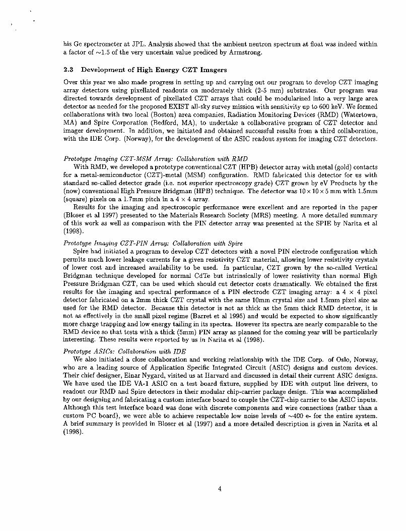
The actual field distribution in the IMARAD/PIN detector is shown for two bias voltages (500 and lOOOV) in Fig. 5, as measured for us by W. Yao (at Sandia Labs) using a crossed-polarization technique (see Yao et al. 1998). This shows that the high-field region (bright) has increased by -50%, consistent with Fig. 4, and that the deposition (at Spire) of the gold-chloride cathode was probably non-uniform. Evaporative gold will be used for the cathode in our next IMARAD/PIN detector.
We have obtained IR micrographs (courtesy W. Yao, Sandia) of the bare samples to examine their internal structure. The result shows indeed the material is very uniform (as also found by Schlesinger et al. 1998) as compared with results for eV Products material shown by Szeles and Driver (1998).
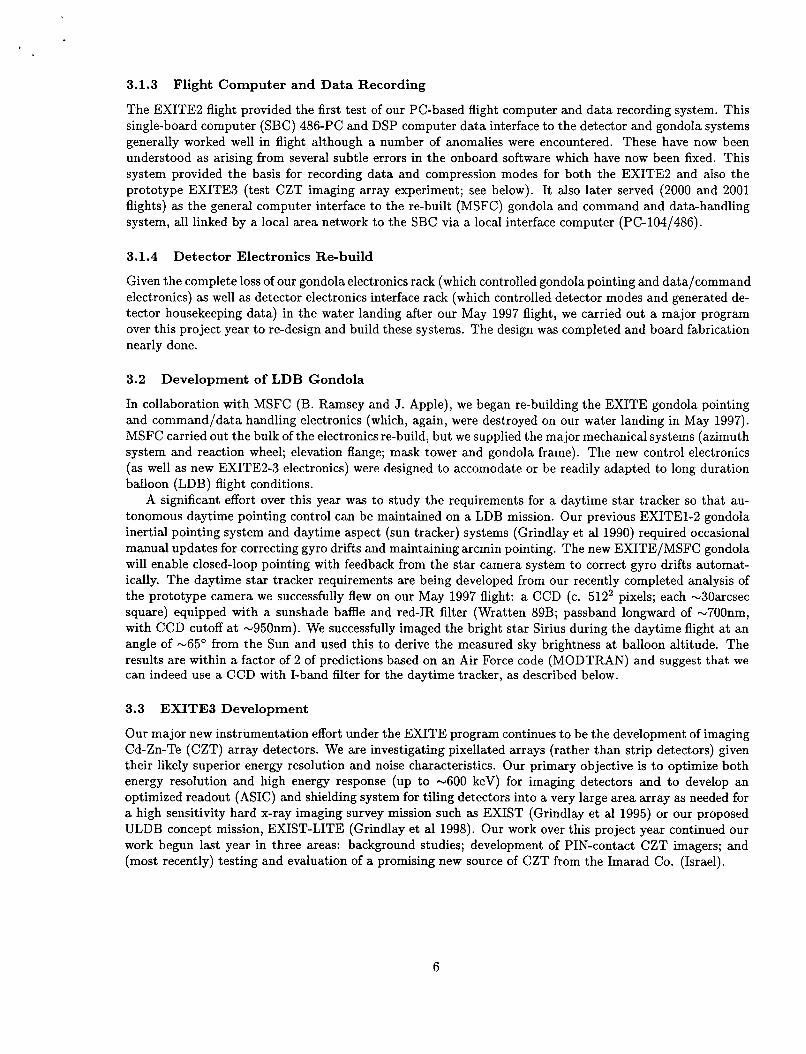
We have also measured the electron mobility in IMARAD CZT (see Fig. 6) and find it is a factor of -2 lower than for our 5mm thick eV (non-PIN) imager. Sample variations of course exist, and this eV sample was the high resistivity (spectroscopic grade) sample, but we conclude tentatively the IMARAD material may have somewhat greater electron trapping over large depths. However, at the high bias voltages we would operate IMARAD material as a PIN detector (see Figs. 4,5), this is not expected to be significant.
9

25000 I 8
0.095
- 0.09
5 0.085 4 2 0.08
0.075
.s 0.07
2
Y (D
Y
m
20000
15000 I
C
10000 s
5000
0
- -
- - -
-
1000 1500 2000 2500 3000 Channels
16000 I I
14000
12000
10000 u) 1
5 8000 8
6000
4000
2000
0 1000 1500 2000 2500 3000
Channels
Figure 3: Energy spectra for 241Am (60 keV) obtained with a) IMARAD (normal: In contacts) and b) IMARAD PIN (with Au contacts.
0.1
, I
0.055
0.05 -200 -300 -400 -500 -600 -700 -800 -900 - 1 0 0 0 - 1 1 0 0
HV Bias (Volts)
Figure 4: Line ratio vs. bias voltage.
10
Figure 5: Electric field distribution at 500 & 1OOOV.
0 200 400 600 800 1000 HV (Volts)
Figure 6: p r curves for IMARAD vs. eV CZT.
11

Figure 7: Flight prototype tiled CZT array (2 detectors) and ASIC readout with shield/collimator. Left: conceptual layout, and Right: actual flight hardware.
Additional measurements of other IMARAD vs. eV samples are in progress, as well as environmental (e.g. temperature sensitivity) and gain stability tests.
Our conclusion is that the IMARAD material is excellent and, with the gold cathode structure and apparent diode-like behaviour, offers the best promise for EXITE3.
4.2
Finally, we have performed two balloon flight tests (September 2000 and May 2001) of IMARAD vs. eV Products CZT crystals (lcm x lcm x 0.5cm) tiled together in a mini-array (1 x 2) crystals, and shielded by a passive photon shield (Pb-Sn-Cu) enclosed by an active (plastic scintillator) particle shield. Each crystal had a 4 x 4 array of anode pixels and was “flip-chip” coupled (conductive epoxy-bonded) to a carrier board (proto-DCA) read out by a 32 channel VA-TA ASIC provided by IDE AS (Hoevik, Norway). The VA-TA is a self triggering ASIC design where all the channels are recorded and readout from a single channel trigger. Details of the CZT2 detector and shield design, as well as testing, were given by Bloser et a1 (1999, 2000).
The balloon flight results obtained with the system shown in Fig. 7 were primarily to measure in-flight detector backgrounds. These were found to agree well with predicted values. Results are reported in Bloser et a1 (2002) and Jenkins et a1 (2003).
CZT2 prototype flight imager and flight background tests
4.3 EXITE2: Final Flight Results
The final two balloon flights for EXITE2, the imaging phoswich detector and coded aperture telescope, were conducted in the September 2000 and May 2001 flights referred to above for their CZT2 (imaging CZT detector background and performance measurements in support of the future EXITE3 system) results. The September 2000 flight included important upper limits on the GRS1227+02 source (cf. Fig. 1 above for the 1997 detection) its did the May 2001 flight. Results are reported in Chou et a1 (2003b). The September flight was of short duration due to unfavorable winds. The May 8,2001, flight was a full success: 18h at float and detection of numerous sources: Crab, Cyg X-1 and the black hole transient GRS1915+05. Interesting upper limits on several other sources were also obtained (including the GRS1227+023 source). Results are summarized in Chou et a1 (2003a). Spectroscopy analysis for these final two flights made use of our new XSPEC tools developed for analysis of the 1997 flight data and reported by Bloser et a1 (2002).
4.4 L D B Gondola Development
Both the September 2000 and May 2001 flights were conducted with the new MSFC gondola, developed from our original EXITE gondola but modified extensively for a new pointing system in response to the loss of our original system (gondola electronics) in the May 1997 water landing. The new gondola incorporates many systems needed for our long-term goal of LDB flight status of a new (CZT) EXITE3 imaging detector and survey telescope system - the focus of our follow-on SR&T grant. The daytime star camera flown on
12

. . the May 2001 flight was a great success, imaging stars down to 8th mag in full daytime conditions. This camera, incorporating much smaller CCD pixels (and thus lower sky diffuse background) than in our original tests in the 1997 flight, will be the basis for daytime aspect for EXITE3. The new pointing system, with closed-loop servo (to update gyro drifts from star camera aspect) will also be incorporated into our planned new EXITE3 gondola.
5 References
Note: references with first author in bold are papers for which the primary work was done, at least in part, under this grant.
1.
2.
3.
4.
5.
6.
7.
8.
9.
10.
11.
12.
13.
14.
15.
16.
17.
18.
19.
20.
21.
22.
23.
24.
25.
26.
Armstrong, T. et a1 1973, JGR, 78 (16), 2715.
Barrett, H., Eskin, J. and Barber, H. 1995, Phys. Rev. Lett., 75, 156.
Bloser, P., Grindlay, J. Narita, T. and Shah, K. 1997, Proc. MRS, 487, 153.
Bloser, P., Grindlay, J., Narita, T. and Harrison, F. 1998a, Proc. SPIE, 3445, 186.
Bloser, P., Grindlay, J. Narita, T. and Shah, K. 1998b, Proc. MRS, 487, 153.
Bloser, P., Grindlay, J. Narita, T., and Jenkins, J. 1999, Proc. SPIE, 3765, 388.
Bloser, P.,Narita T., Jenkins, J . and Grindlay, J. 2000, Proc. SPIE, 4140, 237.
Bloser, P., Narita, T., Jenkins, J., Perrin, M., Murray, R. and Grindlay, J . 2002, Proc. SPIE, 4497, 88.
Bloser, P. F., Chou, Y., Grindlay, J . E. Narita, T., and Monnelly, G. 2002, Astroparticle Phys., 17, 393.
Chou, Y., Bloser, P., Grindlay, J. et a1 1999a, Proc. IEEE, conf. proceedings.
Chou, Y., 2001, Ph.D. Thesis, Harvard.
Chou, Y., Bloser, P., Grindlay, J., Jenkins, J. and Narita, T. 2003a, ApJ, in press (CygX-1).
Chou, Y., Bloser, P., Grindlay, J., Jenkins, J . and Narita, T. 2003b, ApJ, in press (GRS1227+023).
Grindlay, J., Garcia, M., Burg, R. and Murray, S. 1986, IEEE Trams. NUC. Sci., NS-33, 750.
Grindlay, J. 1993, A&AS, 97, 113.
Grindlay, J . 1998, Astron. Nach., 319, 133.
Grindlay, J., Garcia, M., Burg, R. and Murray, S. 1986, IEEE Trams. NUC. Sci., NS-33, 750.
Grindlay, J. et a1 1995, Proc. SPIE, 2518, 202.
Grindlay, J . et al 1997, in Proc. ASM Workshop, Riken Workshop, Waco, Japan(M. Matsuoka and N. Kawai, eds.), 247.
Grindlay, J. 1998, Adw. Sp. Res., 21 (No. 7), 999.
Jenkins, J., Narita, T., Grindlay, J., Bloser, P., Stahle, C., Parker, B., Barthelmy, S., 2003 Proc. SPIE, 4851, 866.
Jourdain, E. et al. 1992, A p J , 395, L69.
Lum, K. et a1 1994, Proc. IEEE, NS-41, 1354.
Narita, T., Bloser, P., Grindlay, J., et a1 1998, Proc. SPIE, 3446, 218.
Narita, T., Bloser, P., Grindlay, J., Jenkins, J. and Yao, H. 1999, Proc. SPIE, 3768, 55.
Narita, T., Bloser, P., Grindlay, J., Jenkins, J . and Yao, H., 2000, Proc. SPIE, 4141, 89.
13


![Caning of Senator Sumner, Part Three - Furman …facweb.furman.edu/~bensonlloyd/sumner/SumnerPart3ver1b.doc · Web view[The Caning of Senator Sumner] [Part Three] [H1]Part Three:](https://static.fdocuments.net/doc/165x107/5aa7a2597f8b9a6d5a8c9eae/caning-of-senator-sumner-part-three-furman-bensonlloydsumnersumnerpart3ver1bdocweb.jpg)

