INTRODUCTION - Stratasys 3D Printing | CATI POLYJET 3D PRINTED MOLDS: THE MODERN ALTERNATIVE PolyJet...
8
FOR A 3D WORLD TM White Paper INTRODUCTION Injection molding (IM) — the process of injecting plastic material into a mold cavity where it cools and hardens to the configuration of the cavity — is best used to mass-produce highly accurate, and often complex, three dimensional (3D) end-use parts and products. However, the development of molds for this process is often painstaking, highly expensive and time intensive. Hard-tooling molds are usually made from tool steel with a CNC milling machine or via electrical discharge machining (EDM). When used in mass production, they can last for millions of cycles but cost hundreds of thousands of dollars. What’s more, lead times to produce these molds are often measured in months rather than weeks or days. When tens of thousands of injection molded parts are needed, soft-tooling is an option. Made in aluminum, these molds are less expensive (typically $2,500 - $25,000) and faster to produce (2 - 6 weeks). Unfortunately, the cost and time of tooling molds is often compounded by factors like design mistakes that require the mold be remade correctly or the need to create multiple iterations before the final part design and quality are achieved. It is with these issues in mind that manufacturers have begun to embrace the use of 3D printed molds to create functional IM prototypes. PRECISION PROTOTYPING THE ROLE OF 3D PRINTED MOLDS IN THE INJECTION MOLDING INDUSTRY By Lior Zonder & Nadav Sella
Transcript of INTRODUCTION - Stratasys 3D Printing | CATI POLYJET 3D PRINTED MOLDS: THE MODERN ALTERNATIVE PolyJet...

F O R A 3 D W O R L D TM
White Paper
INTRODUCTION
Injection molding (IM) — the process of injecting plastic material into a mold cavity where it cools and hardens to the configuration of the cavity — is best used to mass-produce highly accurate, and often complex, three dimensional (3D) end-use parts and products. However, the development of molds for this process is often painstaking, highly expensive and time intensive.
Hard-tooling molds are usually made from tool steel with a CNC milling machine or via electrical discharge machining (EDM). When used in mass production, they can last for millions of cycles but cost hundreds of thousands of dollars. What’s more, lead times to produce these molds are often measured in months rather than weeks or days.
When tens of thousands of injection molded parts are needed, soft-tooling is an option. Made in aluminum, these molds are less expensive (typically $2,500 - $25,000) and faster to produce (2 - 6 weeks).
Unfortunately, the cost and time of tooling molds is often compounded by factors like design mistakes that require the mold be remade correctly or the need to create multiple iterations before the final part design and quality are achieved. It is with these issues in mind that manufacturers have begun to embrace the use of 3D printed molds to create functional IM prototypes.
PRECISION PROTOTYPINGTHE ROLE OF 3D PRINTED MOLDS IN THE INJECTION MOLDING INDUSTRY
By Lior Zonder &Nadav Sella

2
POLYJET 3D PRINTED MOLDS: THE MODERN ALTERNATIVE
PolyJet technology is an exclusive method of 3D printing offered by Objet™ 3D Printers from Stratasys® that gives companies the ability to build injection molds in-house, quickly and easily. PolyJet printing creates 3D objects by positioning successive layers of liquid photopolymer into desired configurations. The plastic is then cured (solidified) with UV light. Once fully cured, molds can immediately be placed into IM equipment and used to create prototypes from the same material that is specified for use in the final product. These precision prototypes give manufacturers the ability to create realistic, finished-product examples that can then be used to gather true-to-life, performance data.
PolyJet injection molds are not intended to be replacements for soft or hard tools used in mid- and high volume production. Rather, they are intended to fill the gap between soft tool molds and 3D printed prototypes. The following chart (Figure 1) illustrates the niche PolyJet technology fills in the prototype development process.
Methods of Producing Prototypes
Optimal Quantity of Parts
Material Used to Produce Prototype
Average Mold Cost
Average Cost/Part
Average Time/Part
3D Printing* 1-10 FDM or PolyJet Plastic N/A High High
Machine Milling 1 – 100 Thermoplastic N/A High Medium
Silicone Molding 5 – 100 Thermoset Low Medium High
Injection molding using PolyJet 3D printed mold
10 – 100 Thermoplastic Low Medium Medium
Injection molding using Soft Tools
100 – 20,000+ Thermoplastic High Low Very Low
Figure 1: The characteristics of PolyJet printing versus traditional prototype production methods.
* Although FDM and laser-sintered processes use thermoplastics to create prototypes, the mechanical properties will not match those of an actual injection molded part because a) the processes used to create the prototypes will be different, and b) the materials used to create FDM and laser-sintered prototypes are not generally the same as those materials used to injection mold final parts
Key points related to PolyJet molds:
• The initial cost of creating a PolyJet mold is relatively low. However, PolyJet molds are best suited for runs ranging up to 100 parts depending on the type of thermoplastic used and mold complexity. As a result, the cost per part is medium.
• Building a PolyJet mold is relatively quick; a mold can be built within a few hours as compared to days or weeks to create traditional molds.
• In cases where design changes are required, a new iteration of the mold can be created in-house at minimal cost. This, combined with the speed of PolyJet 3D printing, allows designers and engineers greater design freedom.
• Molds created in Digital ABS material can be precisely built in 30 micron layers, with accuracy as high as 0.1 mm. These production features create a smooth surface finish so post-processing is not needed in most cases.

3
• Complex geometries, thin walls, and fine details can easily be programmed into the mold design. What’s more, these molds cost no more to make than simpler molds.
• No pre-programming is needed to create PolyJet molds. Also, once the CAD design files are loaded, the 3D printing process can run without manual intervention.
• The manufacturing time to injection mold a part using a PolyJet mold is relatively low, although not as low as conventional molding.
MATERIAL SELECTION
Proper material selection is important for success when injection molding using PolyJet molds.
Digital ABS is the best choice for printing IM molds; it combines strength and toughness together with high temperature resistance. Other PolyJet materials like rigid FullCure®720 and Vero also perform well as IM molds. However, when used to create parts with complex geometries, molds made from these materials will have shorter lives than those made with Digital ABS.
The best materials for creating injection molded parts are those that have reasonable molding temperatures (< 570 °F / 300 °C) and good flow behavior. Ideal candidates are:
• Polyethylene (PE)
• Polypropylene (PP)
• Polystyrene (PS)
• Acrylonitrile Butadiene Styrene (ABS)
• Thermoplastic elastomer (TPE)
• Polyamide (PA)
• Polyoxymethylene or Acetal (POM)
• Polycarbonate-ABS blend (PC-ABS)
• Glass-filled polypropylene or glass-filled resin (G)
Plastics requiring processing temperatures of 250°C (480°F) and higher, or those that have high viscosity at their processing temperature, will shorten the life of the mold, and in some cases, the quality of the finished part.
The chart at right (Figure 2) outlines the relative number of parts that are typically produced using the different tooling methods.
* Numbers will change depending on geometries and sizes of IM parts.
A= • Polyethylene (PE) • Polypropylene (PP) • Polystyrene (PS) • Acrylonitrile Butadiene Styrene (ABS) • Thermoplastic elastomer (TPE)
B= • Glass-filled Polypropylene (PP+G) • Polyamide (PA) • Acetal (Polyoxymethylene [POM]) • Polycarbonate-ABS blend (PC+ABS)
C= • Glass-filled Polyamide (PA+G) • Polycarbonate (PC) • Glass-filled Acetal (POM+G)
D= • Glass-filled Polycarbonate (PC+G) • Polyphenylene Oxide (PPO) • Polyphenylene Sulfide (PPS)
Figure 2: Anticipated Number of Parts by Material Class*

4
It is also useful to take a look at the following cost benefit analysis to understand how the use of injection molding with a PolyJet mold compares to injection molding with an aluminum mold.
Aluminum Digital ABS
Cost Lead Time Cost Lead Time Components
Fan rotor made of POM
$1,670 7 days $960 1 day • Objet500 Connex • 810gr RGD535 • 1408gr RGD515 • 100gr support
Set of six (6) ice cream spoons made from PP
$1,400 30 days $785 7 hours • Objet260 Connex • 400gr RGD535 • 480gr RGD515 • 100gr support
Threaded cap made from various materials
$1,900 4 days $530 13 hours • Objet350 Connex• 500gr RGD535 • 876gr RGD515 • 100gr suppor
Figure 3: Cost Benefit Analysis in Terms of Construction Time and Cost (comparison with aluminum molds)
As can be seen in the examples above, the time savings were highly significant, ranging between a few days and several weeks. Additionally, the cost to produce the molds was generally 40% - 70% cheaper.
FIELD TESTING
Stratasys along with Nypro Healthcare, a global manufacturer of precision plastic products for the health care and packaging industries located in Bray, Ireland, conducted a series of tests to assess the performance of rapid prototyped cores and cavities with critical features that included:
• Gears
• Ratchets
• Interlocking legs
• Catch features
5
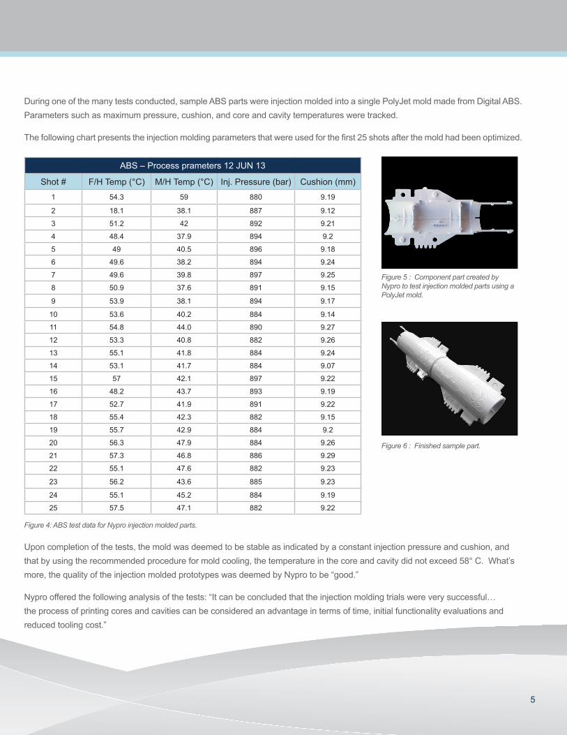
During one of the many tests conducted, sample ABS parts were injection molded into a single PolyJet mold made from Digital ABS. Parameters such as maximum pressure, cushion, and core and cavity temperatures were tracked.
The following chart presents the injection molding parameters that were used for the first 25 shots after the mold had been optimized.
ABS – Process prameters 12 JUN 13
Shot # F/H Temp (°C) M/H Temp (°C) Inj. Pressure (bar) Cushion (mm)
1 54.3 59 880 9.19
2 18.1 38.1 887 9.12
3 51.2 42 892 9.21
4 48.4 37.9 894 9.2
5 49 40.5 896 9.18
6 49.6 38.2 894 9.24
7 49.6 39.8 897 9.25
8 50.9 37.6 891 9.15
9 53.9 38.1 894 9.17
10 53.6 40.2 884 9.14
11 54.8 44.0 890 9.27
12 53.3 40.8 882 9.26
13 55.1 41.8 884 9.24
14 53.1 41.7 884 9.07
15 57 42.1 897 9.22
16 48.2 43.7 893 9.19
17 52.7 41.9 891 9.22
18 55.4 42.3 882 9.15
19 55.7 42.9 884 9.2
20 56.3 47.9 884 9.26
21 57.3 46.8 886 9.29
22 55.1 47.6 882 9.23
23 56.2 43.6 885 9.23
24 55.1 45.2 884 9.19
25 57.5 47.1 882 9.22
Figure 4: ABS test data for Nypro injection molded parts.
Upon completion of the tests, the mold was deemed to be stable as indicated by a constant injection pressure and cushion, and that by using the recommended procedure for mold cooling, the temperature in the core and cavity did not exceed 58° C. What’s more, the quality of the injection molded prototypes was deemed by Nypro to be “good.”
Nypro offered the following analysis of the tests: “It can be concluded that the injection molding trials were very successful… the process of printing cores and cavities can be considered an advantage in terms of time, initial functionality evaluations and reduced tooling cost.”
Figure 6 : Finished sample part.
Figure 5 : Component part created by Nypro to test injection molded parts using a PolyJet mold.

6
BEST PRACTICE GUIDELINES
Injection mold design, an art in itself, requires years of experience and a profound understanding of the injection molding process. Although the design considerations for creating and using a PolyJet mold are fundamentally the same as traditionally crafted molds, there are some variations. Tool designers should consider the following changes when creating a PolyJet mold as opposed to a conventional steel mold design.
1. DESIGNING THE MOLD
• Increase draft angles as much as the part design allows. This will facilitate ejection and reduce stress on the tool as the part is ejected.
• Increase gate size to reduce shear stress.
• The gate should be located so that the melt entering the cavity will not impinge on small/thin features in the mold.
• Avoid using tunnel gates and point gates. Instead, use gates that reduce shear such as a sprue gate or edge gate.
2. PRINTING THE MOLD
To maximize the opportunities created by PolyJet 3D printing, the following guidelines are recommended:
• Print in glossy mode to ensure smoothness.
• Orient the part in Objet Studio™ software so that the glossy surfaces are maximized.
• Orient the mold so that the flow of polymer is in the same direction as the print lines.
Figure 10: Orient the part in Objet Studio software so that glossy surfaces are maximized. Left: When the mold is oriented in the Y axis, threads will be configured by support material. Right: When the mold is oriented in the Z axis, threads will be automatically configured without support material.
Figure 7 : PolyJet injection mold made with Digital ABS along with a 20% GF nylon part.
Figure 8 : PolyJet mold inserts on the molding machine. Left is the core and right is the cavity.
Figure 9: Ejection system fitted to the 3D printed insert.

7
3. FINISHING THE MOLD
A key benefit of PolyJet molds is that they can be designed, built and used within hours. Most will require little or no post-processing work, however further finishing may be needed if:
• The mold will be fitted to an ejection system.
To ensure a tight fit between the ejector pins and the ejector pin holes, program the holes into the STL file but reduce their diameter by 0.2 - 0.3mm. Then, when the mold is cured, ream the holes to the exact final size.
• Inserts are being fitted onto a base.
• Extra smoothing of surfaces is needed.
Occasionally, light sanding of surfaces transverse to the mold opening is recommended. For example. prior to using a mold with a tall core, some light smoothing can facilitate part removal.
4. MOUNTING
• Stand-alone molds — those that are not constrained to a base frame — can be mounted directly onto standard or steel machine back-plates using screws or double-sided tape.
• Figure 8 mold inserts are fitted onto a base mold using bolts.
With any chosen mounting option, it is critical to avoid direct contact between the nozzle and the printed mold by using standard sprue bushing. An alternative option would be to center the mold’s runner with the sprue located on a regular steel plate.
5. INJECTION MOLDING PROCESS
When using the PolyJet mold for the first time, the best practice procedure is:
• Start with a short shot and a slow injection speed. The fill time can be high as the melt does not freeze off as it enters the mold. Increase shot size until the cavity is 90-95% full.
• In the holding process, use 50-80% of actual injection pressure and adjust the holding time as needed to avoid sink marks.
• Apply normal calculated clamping force value (injection pressure x projected part area) as initial value.
Figure 12: Stand-alone mold held with double sided tape to the mold machine’s back plates.
Figure 11: Finishing process of mold component.
Figure 13: Mold inserts are assembled on a standard steel base and held in place with machine screws.
Figure 14: Cooling fixture mounted on the mold. As the mold opens, pressurized air is applied to the surface for a predetermined time.

©2013 Stratasys Inc. All rights reserved. Stratasys, Fortus, Dimension, uPrint and FDM are registered trademarks and Fused Deposition Modeling, FDM Technology are trademarks of Stratasys Inc., registered in the United States and other countries. All other trademarks are the property of their respective owners. Product specifications subject to change without notice. Printed in the USA. SSYS-WP-IM-09-13
For more information about Stratasys systems, materials and applications, call 888.480.3548 or visit www.stratasys.com
7665 Commerce WayEden Prairie, MN 55344+1 888 480 3548 (US Toll Free)+1 952 937 3000 (Intl)+1 952 937 0070 (Fax)
2 Holtzman St., Science Park, PO Box 2496 Rehovot 76124, Israel +972 74 745-4000 +972 74 745-5000 (Fax)
ISO 9001:2008 Certified
Stratasys | www.stratasys.com | [email protected]
• PolyJet molds have low thermal conductivity so they will require extended cooling times. For small or thin parts (wall thickness of 1mm or less), start with a 30 second cooling time and adjust as needed. For larger parts (wall thickness of 2mm or more), start with 90 seconds and adjust accordingly. The cooling time will vary depending on the type of plastic resin used.
• Minimum cooling is recommended to avoid too much shrinkage of the part on the printed cores. Extensive cooling may stress the mold when the part is being ejected and cause it to fail.
• After each molding cycle, it is critical to allow the mold’s surface to cool by applying pressurized air. This will preserve part quality and mold life. Alternatively, automated mold cooling fixtures may be used.
CONCLUSION
The use of PolyJet 3D printed molds allows manufacturers the ability to take functional testing to a new level, by creating product prototypes from the same IM process and materials that will be used to create the final product. With this technology, companies can generate superior performance data and validate certification confidence.
PolyJet molds are unique in that they perform in the same way as metal molds but are much cheaper, easier and faster to make. With PolyJet technology, manufacturers can produce prototypes at speeds and costs far below traditional methods. As a result, 3D printing allows manufacturers to easily evaluate the performance, fit and quality of potential products before mass production starts.
BEST FIT PARAMETERS
PolyJet molds are a best fit for the application when working with:
Thermoplastics:• Reasonable molding temperatures < 300° C (570° F)
• Good flow behavior
• Candidates:
- Polyethylene (PE)
- Polypropylene (PP)
- Polystyrene (PS)
- Acrylonitrile Butadiene Styrene (ABS)
- Thermoplastic elastomer (TPE)
- Polyamide (PA)
- Polyoxymethylene or Acetal (POM)
- Polycarbonate - ABS blend (PC-ABS)
- Glass-filled resins
Quantity:• Low quantities (5 to 100)
Size:• Mid-sized parts <165 cm3 (10 in3)
• 50 to 80-ton molding machines
• Manual hand presses can also be used.
Design:• Multiple design iterations are required.
Testing:• Functionality confirmation is required.
• Compliance testing (e.g., UL or CE) is required.