INTRODUCTION - riello-ups.com
48
Transcript of INTRODUCTION - riello-ups.com


3
INTRODUCTION
Thank you for choosing our product. The accessories described in this manual are of the highest quality, carefully designed and built in order to ensure excellent performance. This manual contains detailed instructions on how to install and use the product. This manual must be stored in a safe place and CONSULTED BEFORE USING THE DEVICE for proper usage instructions as well as maximum performance from the device itself. NOTE: Some images contained in this document are for informational purposes only and may not faithfully demonstrate the parts of the product they represent. Symbols used in this manual:
Danger Indicates the possible presence of dangerous voltages and the risk of electric shock.
Warning Indicates important information that must not be ignored.
Information Provides notes and useful suggestions for the User.
SAFETY
This part of the manual contains SAFETY precautions that must be followed scrupulously. Ensure that the connectors subjected to high voltages are correctly isolated.
❖ The device has been designed for professional use and is therefore not suitable for use in the home.
❖ The device has been designed to operate only in closed environments. It should be installed in rooms where there are no inflammable liquids, gas or other harmful substances.
❖ Take care that no water or liquids and/or foreign bodies fall into the device.
❖ In the event of a fault and/or impaired operation of the device, do not attempt to repair it but contact the authorized service centre.
❖ The device must be used exclusively for the purpose for which it was designed. Any other use is to be considered improper and as such dangerous. The manufacturer declines all responsibility for damage caused by improper, wrong and unreasonable use.

4
ENVIRONMENTAL PROTECTION
Our company devotes abundant resources to analysing environmental aspects in the development of its products. All our products pursue the objectives defined in the environmental management system developed by the company in compliance with applicable standards. Hazardous materials such as CFCs, HCFCs or asbestos have not been used in this product. When evaluating packaging, the choice of material has been made favouring recyclable materials. Please separate the different material of which the packaging is made and dispose of all material in compliance with applicable standards in the country in which the product is used.
DISPOSING OF THE PRODUCT
The device contains internal material which (in case of dismantling/disposal) are considered TOXIC, such as electronic circuit boards. Treat these materials according to the laws in force, contacting qualified centres. Proper disposal contributes to respect for the environment and human health. © The reproduction of any part of this manual, even in part, is prohibited unless authorised by the manufacturer.
The manufacturer reserves the right to change the product described at any time without prior notice for improvement purposes.

5
CONTENTS
DESCRIPTION 7
KIT CONTENTS 7
DESCRIPTION AND CHARACTERISTICS 7
OPERATION 8 INPUT 8 OUTPUT 9 ROTARY SWITCHES SW # 10 DELAY TIME 10
CARD INSTALLATION 11
PROTECTION IN CASE OF DANGEROUS VOLTAGE SIGNALS 11
CARD CONFIGURATION 12
SERIES VST / VSD 13 INPUT #1 14 INPUT #2 14 INPUT #3 16 OUTPUT CONTACTS CONFIGURATION 17
SERIES SEP / SDH / SDU (4KVA) 18 INPUT #1 18 INPUT #2 19 INPUT #3 20 OUTPUT CONTACTS CONFIGURATION 21
SERIES SDL (3.3÷4KVA) 22 INPUT #1 22 INPUT #2 23 INPUT #3 24 OUTPUT CONTACTS CONFIGURATION 25
SERIES SDL (5÷6KVA) / SPT / SPW 26 INPUT #1 26 INPUT #2 27 INPUT #3 28 OUTPUT CONTACTS CONFIGURATION 29
SERIES SDU (5÷10KVA) / STW 30 INPUT #1 30 INPUT #2 31 INPUT #3 32 OUTPUT CONTACTS CONFIGURATION 33
SERIES SPH 34 INPUT #1 35 INPUT #2 35 INPUT #3 36 OUTPUT CONTACTS CONFIGURATION 37
SERIES MST / MSM / MCT / MCM / C1T / C1M / GMI 38 INPUT #1 38 INPUT #2 39 INPUT #3 39 OUTPUT CONTACTS CONFIGURATION 40
SERIES S3T / S3M / S3U 41 INPUT CONFIGURATION 43 OUTPUT CONTACTS CONFIGURATION 44
SERIES MPW / MPX 45 INPUT CONFIGURATION 45 OUTPUT CONTACTS CONFIGURATION 45

6

7
DESCRIPTION
KIT CONTENTS
• MultiCOM 384 card
• Metal slot cover
• Protection cover
• Protection shells
• Cable gland
• Screws
DESCRIPTION AND CHARACTERISTICS
The MultiCOM 384 card allows to remote the commands to turn off and/or turn on the UPS and some UPS status. The card must be inserted in the UPS dedicated slot. This card is compatible with most UPS products in our portfolio, but some features may not be available on some UPS. Please read carefully this guide to properly configure the board and the UPS. The MultiCOM 384 card has two removable terminal blocks. On the first (4 poles, named J1) there are the control signals to the UPS (eg the command to turn off the UPS), while on the second (8 poles, named J3) there are the outputs of 4 exchange relays for the signals coming from the ' UPS (eg contact for signaling battery operation).
ALLOCATION OF CONFIGURATION SWITCHES AND THE TERMINAL BOARDS
J3
J1

8
OPERATION
INPUT
MultiCOM 384 has 3 inputs to control the UPS:
• INPUT #1
• INPUT #2
• INPUT #3
Terminal block J1 - Input pinout
INPUT #1
INPUT #1 is generally dedicated to remote on.
NOTE: in some UPS the function assigned to INPUT #1 is configurable.
INPUT #2
INPUT #2 is generally dedicated to remote off.
NOTE: in some UPS the function assigned to INPUT #2 is configurable.
INPUT #3
INPUT #3 is generally dedicated to bypass command (Service bypass or Load on bypass).
NOTE:
• In some UPS the function assigned to INPUT #3 is configurable.
• Configuring properly the card, you can get a + 12Vdc isolated auxiliary power as an alternative to the INPUT #3.
NOTE: some UPS may not handle all inputs or have different default configuration. Check the features that are compatible with your UPS model in the chapter "CARD CONFIGURATION"

9
OUTPUT
MultiCOM 384 card has 4 dry contacts associated to the UPS status and/or alarms:
• OUTPUT #1
• OUTPUT #2
• OUTPUT #3
• OUTPUT #4 Generally the output contacts are already associated with events; however, in many UPS series, these associations can be modified through the configuration software.
OUTPUT 1 2 3 4
EVENT BATTERY LOW BATTERY WORKING INVERTER LOCKED LOAD ON BYPASS
RELAY RL1 RL2 RL3 RL4
CONTACT N.O. N.O. N.C. N.C. N.O. N.C.
PIN # 7 6 5 3 2 1
NOTE: check the features that are compatible with your UPS model and the default configuration in the "CARD CONFIGURATION" chapter.
The figure below shows the internal connections between the Relay contacts (two relays with switched contacts, a normally closed contact (N.C.) relay and a normally open contact (N.O.) relay and terminal block J3.
CONTACTS ON THE INTERNAL RELAYS AND CONNECTION TO THE TERMINALS
NOTE: to provide more flexibility to the installations, relays have been divided into two groups. In this way, the two relay groups can work with two different working voltages, or work on two separate systems.
ATTENTION: you can apply a maximum voltage of 250 V and a maximum current of 3 A for each pin.

10
ROTARY SWITCHES SW #
The rotary switches SW1-SW2-SW3-SW4 can be used to modify the association between UPS outputs and relays.
NOTE: it is possible to associate the same signal to two or more relays.
RELAY ROTARY SW UPS OUTPUT
RELAY 1 SW1
POS. 1 OUTPUT #1
POS. 2 OUTPUT #2
POS. 3 OUTPUT #3
POS. 4 OUTPUT #4
RELAY 2 SW2
POS. 1 OUTPUT #1
POS. 2 OUTPUT #2
POS. 3 OUTPUT #3
POS. 4 OUTPUT #4
RELAY 3 SW3
POS. 1 OUTPUT #1
POS. 2 OUTPUT #2
POS. 3 OUTPUT #3
POS. 4 OUTPUT #4
RELAY 4 SW4
POS. 1 OUTPUT #1
POS. 2 OUTPUT #2
POS. 3 OUTPUT #3
POS. 4 OUTPUT #4
ATTENTION: before change the position of the switches on SW # rotary switches, check the features that are compatible with your UPS model in the "CONFIGURATION CARD" chapter.
DELAY TIME
By switching on the dip switch SW6, it is possible to delay the switching (8-10 seconds) in respect to the activation of the control signal. This delay can be useful for filtering short unwanted conditions such as instantaneous network interruptions, bypass operations for distorted loads, and so on. Each switch is associated with a relay, and by default all switches are in OFF position.
DIP SWITCH SW6: EXAMPLE ACTIVATION DELAY FOR RELAY RL2
NOTE: the delay activation has effect on the closing and on the opening of the relay together.

11
CARD INSTALLATION
ATTENTION: make sure you have correctly configured the MultiCOM 384 card before install it in the UPS. Incorrect configuration may cause card malfunction, immediate shutdown of the UPS, and consequent loss of load. To properly configure the card, refer to the chapter "CONFIGURATION CARD" in this manual.
• Remove the cover of the device expansion slot by removing the two retaining screws
• Insert MultiCOM 384 in the slot.
• Close the slot with the cover supplied in the kit and fasten it in place using the two screws that were removed previously.
ATTENTION: failure to fix the card could cause its malfunction.
• At the end of the installation, it is recommended to cover the two terminal blocks with the shells supplied in the KIT. This will avoid accidental contacts with the terminals when using signal circuits with dangerous voltages.
PROTECTION IN CASE OF DANGEROUS VOLTAGE SIGNALS
An additional protection cover and two protection shells are provided with the kit. Insert the card into the slot, lock it with the metal cover and then, if the 4 fixing holes are present on the UPS, assemble the protection cover. Otherwise, if the fixing holes are not present, assemble the two protection shells.
PROTECTION SHELLS
PROTECTION
COVER
CABLE GLAND

12
CARD CONFIGURATION
The MultiCOM 384 card is compatible with most UPS series. This chapter will show board settings and features for each UPS series. Refer to the code on the UPS data plate to trace back to the UPS model you own (ex. P/N: CSDUK10AA5...).
SWITCH / JUMPER / TERMINALS DEFAULT CONFIGURATION
SW5 (UPS MODEL) A
JP7 (PIN STRIP) OPEN
JP8 (PIN STRIP) OPEN
JP9 (PIN STRIP) OPEN
JP5 (PIN STRIP) 2-3
JP6 (PIN STRIP) 2-3
J1 (4 WAYS TERMINAL) 3-4
DEFAULT CONFIGURATION

- VST / VSD -
13
SERIES VST / VSD
SWITCH / JUMPER / TERMINALS BASIC CONFIGURATION OPTIONS
SW5 (UPS MODEL) A FIXED
JP7 (PIN STRIP) CLOSED FIXED
JP8 (PIN STRIP) OPEN FIXED
JP9 (PIN STRIP) OPEN FIXED
JP5 (PIN STRIP) 2-3 FIXED
JP6 (PIN STRIP) 1-2 CONFIGURABLE
J1 (4 WAYS TERMINAL) 3-4 CONFIGURABLE
BASIC CONFIGURATION

- VST / VSD -
14
INPUT #1
CONFIGURABLE INPUT
You can assign different functions to the INPUT #1via the UPS configuration software. The default configuration for INPUT #1 is NO FUNCTION (input disabled). Possible configurations are:
• No function
• Remote on
• Remote off
• Remote on/off Using a normally open push button / switch connected between pin 2 and 4 of J1 (4-way terminal block), you can activate the function associated with INPUT #1 when the contact is closed.
INPUT #1 - N.O. contact Terminal block J1
Closing the contact, the UPS activates the function associated with the INPUT #1
ATTENTION:
• INPUT #1 does not work if the UPS is powered off and completely switched off.
• After installation, it is advisable to check that the UPS is switched on by the INPUT # 1 input.
• With REMOTE ON, you can open the pin count between pins 2 and 4 when the UPS is started.
INPUT #2
CONFIGURABLE INPUT (1)
You can assign different functions to the INPUT #2 via the UPS configuration software. The default configuration for INPUT #2 is NO FUNCTION (input disabled). Possible configurations are:
• No function
• Remote on
• Remote off
• Remote on/off
INPUT FOR REMOTE SHUTDOWN (2)
You can manage INPUT #2 input either with a N.C contact than with a N.O. contact. NOTE: (1) For VST series. (2) For VSD series.

- VST / VSD -
15
INPUT #2 with N.C. contact
Card configuration:
• Insert the jumper between pins 1 and 2 of JP6 (3-pin strip pins on the card) Using a normally closed push button / switch, connected between pin 3 and pin 4 of J1 (4-way terminal block), you can turn on or off the UPS (depending on the set configuration) when the contact is opened.
INPUT #2 - N.C. contact Position of the jumper on JP6 Terminal block J1
Opening the contact, the UPS activates the function associated with the INPUT #2.
Pin 1-2 on JP6
INPUT #2 with N.O. contact
Card configuration:
• Insert the jumper between pins 2 and 3 of JP6 (3-pin strip pins on the card) Using a normally open push button / switch, connected between pin 3 and pin 4 of J1 (4-way terminal block), you can turn on or off the UPS (depending on the set configuration) when the contact is closed.
INPUT #2 - N.O. contact Position of the jumper on JP6 Terminal block J1
Closing the contact, the UPS activates the function associated with the INPUT #2.
Pin 2-3 on JP6
ATTENTION:
• Setting INPUT #2 with N.C. contact, removing the jumper or 4-pole connector, if the UPS is turned on, it will switch off.
• If you insert the MultiCOM 384 card into the SLOT without the jumper on the J1 connector on the card, the UPS will switch off instantly.
• The shutdown command is an immediate REMOTE OFF command and does not remain in memory in the UPS, so you can restart the UPS again without restoring the original status of the contact.
• INPUT #2 does not replace R.E.P.O. contact of the UPS, but is an additional one, so for the UPS to work properly, do not remove the R.E.P.O. contact located on the back of the UPS. (3)
NOTE: (3) For VSD series.

- VST / VSD -
16
INPUT #3
The MultiCOM 384 board does not handle the INPUT #3 in the VST / VSD series.
Isolated auxiliary power supply + 12Vdc
Card configuration:
• Insert jumper between pin 2 and 3 of JP5 (3-pin strip pins on the card) Modifying the jumper position on the JP5 pin strip, you can get a + 12Vdc isolated auxiliary power instead of INPUT #3, useful for powering small devices such as optocouplers needed to send clean contacts to the UPS.
Isolated aux. power Position of the jumper on JP5 Terminal block J1
+12Vdc ±10% 100mA
Pin 2-3 on JP5
ATTENTION:
• Pins 1 and 4 deliver a maximum of 100mA.
• The supplied voltage is 12Vdc ± 10%.
• An absorption greater than the indicated value, or a short circuit, causes an immediate UPS shutdown due the failure of power supply for INPUT # 1 and INPUT # 2 inputs (configurable as REMOTE OFF).

- VST / VSD -
17
OUTPUT CONTACTS CONFIGURATION
The event associated to OUTPUT #1 and OUTPUT #3 can be configured via software.
OUTPUT DEFAULT CONFIGURABLE
OUTPUT #1 BATTERY LOW YES
OUTPUT #2 BATTERY WORKING NO
OUTPUT #3 ANY ALARM YES
OUTPUT #4 LOAD ON BYPASS NO
VARIATION FOR VSD
NOTE: the configuration software screen is for illustrative purposes. It may vary according to the UPS series and the software version.

- SEP / SDH / SDU (4kVA) -
18
SERIES SEP / SDH / SDU (4KVA)
SWITCH / JUMPER / TERMINALS BASIC CONFIGURATION OPTIONS
SW5 (UPS MODEL) A FIXED
JP7 (PIN STRIP) CLOSED FIXED
JP8 (PIN STRIP) OPEN FIXED
JP9 (PIN STRIP) OPEN FIXED
JP5 (PIN STRIP) 2-3 CONFIGURABLE
JP6 (PIN STRIP) 1-2 CONFIGURABLE
J1 (4 WAYS TERMINAL) 3-4 CONFIGURABIE
BASIC CONFIGURATION
INPUT #1
INPUT FOR REMOTE ON
Using a normally open push button / switch connected between pin 2 and 4 of J1 (4-way terminal block), you can turn on the UPS when the contact is closed.
INPUT #1 –N.O. contact Terminal J1
Closing the contact the UPS turn on.
ATTENTION:
• The UPS can be switched on only if it is powered and in STAND-BY mode.
• INPUT #1 does not work if the UPS is powered off and completely switched off.
• After installation, it is advisable to check that the UPS is switched on by the INPUT # 1 input.
• You can open the pin count between pins 2 and 4 when the UPS is started.

- SEP / SDH / SDU (4kVA) -
19
INPUT #2
INPUT FOR REMOTE OFF
You can manage INPUT #2 input either with a N.C contact than with a N.O. contact.
INPUT #2 with N.C. contact
Card configuration:
• Insert the jumper between pins 1 and 2 of JP6 (3-pin strip pins on the card) Using a normally closed push button / switch, connected between pin 3 and pin 4 of J1 (4-way terminal block), you can turn off the UPS when the contact is opened.
INPUT #2 - N.C. contact Position of the jumper on JP6 Terminal block J1
Opening the contact, the UPS turn off.
Pin 1-2 on JP6
INPUT #2 con contatto N.O.
Card configuration:
• Insert the jumper between pins 2 and 3 of JP6 (3-pin strip pins on the card) Using a normally open push button / switch, connected between pin 3 and pin 4 of J1 (4-way terminal block), you can turn off the UPS when the contact is closed.
INPUT #2 - N.O. contact Position of the jumper on JP6 Terminal block J1
Closing the contact the UPS turn off.
Pin 2-3 on JP6
ATTENTION:
• Setting INPUT #2 with N.C. contact, removing the jumper or 4-pole connector, if the UPS is turned on, it will switch off.
• If you insert the MultiCOM 384 card into the SLOT without the jumper on the J1 connector on the card, the UPS will switch off instantly.
• The shutdown command is an immediate REMOTE OFF command and does not remain in memory in the UPS, so you can restart the UPS again without restoring the original status of the contact.
• INPUT #2 does not replace R.E.P.O. contact of the UPS, but is an additional one, so for the UPS to work properly, do not remove the R.E.P.O. contact located on the back of the UPS.
- SEP / SDH / SDU (4kVA) -
20
INPUT #3
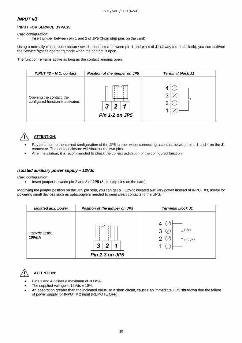
INPUT FOR SERVICE BYPASS
Card configuration: • Insert jumper between pin 1 and 2 of JP5 (3-pin strip pins on the card) Using a normally closed push button / switch, connected between pin 1 and pin 4 of J1 (4-way terminal block), you can activate the Service bypass operating mode when the contact is open. The function remains active as long as the contact remains open.
INPUT #3 – N.C. contact Position of the jumper on JP5 Terminal block J1
Opening the contact, the configured function is activated.
Pin 1-2 on JP5
ATTENTION:
• Pay attention to the correct configuration of the JP5 jumper when connecting a contact between pins 1 and 4 on the J1 connector. The contact closure will shortcut the two pins.
• After installation, it is recommended to check the correct activation of the configured function.
Isolated auxiliary power supply + 12Vdc
Card configuration:
• Insert jumper between pin 2 and 3 of JP5 (3-pin strip pins on the card) Modifying the jumper position on the JP5 pin strip, you can get a + 12Vdc isolated auxiliary power instead of INPUT #3, useful for powering small devices such as optocouplers needed to send clean contacts to the UPS.
Isolated aux. power Position of the jumper on JP5 Terminal block J1
+12Vdc ±10% 100mA
Pin 2-3 on JP5
ATTENTION:
• Pins 1 and 4 deliver a maximum of 100mA.
• The supplied voltage is 12Vdc ± 10%.
• An absorption greater than the indicated value, or a short circuit, causes an immediate UPS shutdown due the failure of power supply for INPUT # 2 input (REMOTE OFF).

- SEP / SDH / SDU (4kVA) -
21
OUTPUT CONTACTS CONFIGURATION
The event associated to OUTPUT #1 and OUTPUT #3 can be configured via software.
OUTPUT DEFAULT CONFIGURABLE
OUTPUT #1 BATTERY LOW YES
OUTPUT #2 BATTERY WORKING NO
OUTPUT #3 INVERTER LOCKED YES
OUTPUT #4 LOAD ON BYPASS NO
NOTE: the configuration software screen is for illustrative purposes. It may vary according to the UPS series and the software version.

- SDL (3,3÷4kVA) -
22
SERIES SDL (3.3÷4KVA)
SWITCH / JUMPER / TERMINALS BASIC CONFIGURATION OPTIONS
SW5 (UPS MODEL) A FIXED
JP7 (PIN STRIP) CLOSED FIXED
JP8 (PIN STRIP) OPEN FIXED
JP9 (PIN STRIP) OPEN FIXED
JP5 (PIN STRIP) 2-3 CONFIGURABLE
JP6 (PIN STRIP) 1-2 CONFIGURABLE
J1 (4 WAYS TERMINAL) 3-4 CONFIGURABIE
BASIC CONFIGURATION
INPUT #1
INPUT FOR REMOTE ON
Using a normally open push button / switch connected between pin 2 and 4 of J1 (4-way terminal block), you can turn on the UPS when the contact is closed.
INPUT #1 – N.O. contact Terminal J1
Closing the contact, the UPS turn on.
ATTENTION:
• The UPS can be switched on only if it is powered and in STAND-BY mode.
• INPUT #1 does not work if the UPS is powered off and completely switched off.
• After installation, it is advisable to check that the UPS is switched on by the INPUT # 1 input.
• You can open the pin count between pins 2 and 4 when the UPS is started.

- SDL (3,3÷4kVA) -
23
INPUT #2
INPUT FOR REMOTE OFF
You can manage INPUT #2 input either with a N.C contact than with a N.O. contact.
INPUT #2 with N.C. contact
Card configuration:
• Insert the jumper between pins 1 and 2 of JP6 (3-pin strip pins on the card). Using a normally closed push button / switch, connected between pin 3 and pin 4 of J1 (4-way terminal block), you can turn off the UPS when the contact is opened.
INPUT #2 - N.C. contact Position of the jumper on JP6 Terminal block J1
Opening the contact, the UPS turn off
Pin 1-2 on JP6
INPUT #2 with N.O. contact
Card configuration:
• Insert the jumper between pins 2 and 3 of JP6 (3-pin strip pins on the card). Using a normally open push button / switch, connected between pin 3 and pin 4 of J1 (4-way terminal block), you can turn off the UPS when the contact is closed.
INPUT #2 - N.O. contact Position of the jumper on JP6 Terminal block J1
Closing the contact the UPS turn off.
Pin 2-3 on JP6
ATTENTION:
• Setting INPUT #2 with N.C. contact, removing the jumper or 4-pole connector, if the UPS is turned on, it will switch off.
• If you insert the MultiCOM 384 card into the SLOT without the jumper on the J1 connector on the card, the UPS will switch off instantly.

- SDL (3,3÷4kVA) -
24
INPUT #3
INPUT FOR SERVICE BYPASS
Card configuration: • Insert jumper between pin 1 and 2 of JP5 (3-pin strip pins on the card) Using a normally closed push button / switch, connected between pin 1 and pin 4 of J1 (4-way terminal block), you can activate the Service bypass operating mode when the contact is open. The function remains active as long as the contact remains open.
INPUT #3 – N.C. contact Position of the jumper on JP5 Terminal block J1
Opening the contact, the configured function is activated.
Pin 1-2 on JP5
ATTENTION:
• Pay attention to the correct configuration of the JP5 jumper when connecting a contact between pins 1 and 4 on the J1 connector. The contact closure will shortcut the two pins.
• After installation, it is recommended to check the correct activation of the configured function.
Isolated auxiliary power supply + 12Vdc
Card configuration:
• Insert jumper between pin 2 and 3 of JP5 (3-pin strip pins on the card) Modifying the jumper position on the JP5 pin strip, you can get a + 12Vdc isolated auxiliary power instead of INPUT #3, useful for powering small devices such as optocouplers needed to send clean contacts to the UPS.
Isolated aux. power Position of the jumper on JP5 Terminal block J1
+12Vdc ±10% 100mA
Pin 2-3 on JP5
ATTENTION:
• Pins 1 and 4 deliver a maximum of 100mA.
• The supplied voltage is 12Vdc ± 10%.
• An absorption greater than the indicated value, or a short circuit, causes an immediate UPS shutdown due the failure of power supply INPUT # 2 input (REMOTE OFF).

- SDL (3,3÷4kVA) -
25
OUTPUT CONTACTS CONFIGURATION
The event associated to OUTPUT #1 and OUTPUT #3 can be configured via software.
OUTPUT DEFAULT CONFIGURABLE
OUTPUT #1 BATTERY LOW YES
OUTPUT #2 BATTERY WORKING NO
OUTPUT #3 INVERTER LOCKED YES
OUTPUT #4 LOAD ON BYPASS NO
NOTE: the configuration software screen is for illustrative purposes. It may vary according to the UPS series and the software version.

- SDL (5÷6kVA) / SPT / SPW -
26
SERIES SDL (5÷6KVA) / SPT / SPW
SWITCH / JUMPER / TERMINALS BASIC CONFIGURATION OPTIONS
SW5 (UPS MODEL) A FIXED
JP7 (PIN STRIP) OPEN FIXED
JP8 (PIN STRIP) OPEN FIXED
JP9 (PIN STRIP) OPEN FIXED
JP5 (PIN STRIP) 2-3 CONFIGURABLE
JP6 (PIN STRIP) 1-2 CONFIGURABLE
J1 (4 WAYS TERMINAL) 3-4 CONFIGURABLE
BASIC CONFIGURATION
INPUT #1
INPUT FOR REMOTE ON
Using a normally open push button / switch connected between pin 2 and 4 of J1 (4-way terminal block), you can turn on the UPS when the contact is closed.
INPUT #1 – N.O. contact Terminal block J1
Closing the contact, the UPS turn on.
ATTENTION:
• The UPS can be switched on only if it is powered and in STAND-BY mode.
• INPUT #1 does not work if the UPS is powered off and completely switched off.
• After installation, it is advisable to check that the UPS is switched on by the INPUT # 1 input.
• You can open the pin count between pins 2 and 4 when the UPS is started.

- SDL (5÷6kVA) / SPT / SPW -
27
INPUT #2
INPUT FOR REMOTE OFF
You can manage INPUT #2 input either with a N.C contact than with a N.O. contact.
INPUT #2 with N.C. contact
Card configuration:
• Insert the jumper between pins 1 and 2 of JP6 (3-pin strip pins on the card). Using a normally closed push button / switch, connected between pin 3 and pin 4 of J1 (4-way terminal block), you can turn off the UPS when the contact is opened.
INPUT #2 - N.C. contact Position of the jumper on JP6 Terminal block J1
Opening the contact, the UPS turn off.
Pin 1-2 on JP6
INPUT #2 with N.O. contact
Card configuration:
• Insert the jumper between pins 2 and 3 of JP6 (3-pin strip pins on the card). Using a normally open push button / switch, connected between pin 3 and pin 4 of J1 (4-way terminal block), you can turn off the UPS when the contact is closed.
INPUT #2 - N.O. contact Position of the jumper on JP6 Terminal block J1
Closing the contact, the UPS turn off.
Pin 2-3 on JP6
ATTENTION:
• To handle the REMOTE OFF command from the MultiCOM 384 board, you must remove the EPO jumper from the corresponding terminal on the back of the UPS.
• Setting INPUT #2 with N.C. contact, removing the jumper or 4-pole connector, if the UPS is turned on, it will switch off.
• If you insert the MultiCOM 384 card into the SLOT without the jumper on the J1 connector on the card, the UPS will switch off instantly.
- SDL (5÷6kVA) / SPT / SPW -
28
INPUT #3
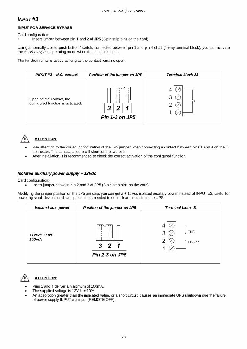
INPUT FOR SERVICE BYPASS
Card configuration: • Insert jumper between pin 1 and 2 of JP5 (3-pin strip pins on the card) Using a normally closed push button / switch, connected between pin 1 and pin 4 of J1 (4-way terminal block), you can activate the Service bypass operating mode when the contact is open. The function remains active as long as the contact remains open.
INPUT #3 – N.C. contact Position of the jumper on JP5 Terminal block J1
Opening the contact, the configured function is activated.
Pin 1-2 on JP5
ATTENTION:
• Pay attention to the correct configuration of the JP5 jumper when connecting a contact between pins 1 and 4 on the J1 connector. The contact closure will shortcut the two pins.
• After installation, it is recommended to check the correct activation of the configured function.
Isolated auxiliary power supply + 12Vdc
Card configuration:
• Insert jumper between pin 2 and 3 of JP5 (3-pin strip pins on the card) Modifying the jumper position on the JP5 pin strip, you can get a + 12Vdc isolated auxiliary power instead of INPUT #3, useful for powering small devices such as optocouplers needed to send clean contacts to the UPS.
Isolated aux. power Position of the jumper on JP5 Terminal block J1
+12Vdc ±10% 100mA
Pin 2-3 on JP5
ATTENTION:
• Pins 1 and 4 deliver a maximum of 100mA.
• The supplied voltage is 12Vdc ± 10%.
• An absorption greater than the indicated value, or a short circuit, causes an immediate UPS shutdown due the failure of power supply INPUT # 2 input (REMOTE OFF).

- SDL (5÷6kVA) / SPT / SPW -
29
OUTPUT CONTACTS CONFIGURATION
The event associated to OUTPUT #1 and OUTPUT #3 can be configured via software.
OUTPUT DEFAULT CONFIGURABLE
OUTPUT #1 BATTERY LOW YES
OUTPUT #2 BATTERY WORKING NO
OUTPUT #3 INVERTER LOCKED YES
OUTPUT #4 LOAD ON BYPASS NO
NOTE: the configuration software screen is for illustrative purposes. It may vary according to the UPS series and the software version.
- SDU (5÷10kVA) / STW -
30
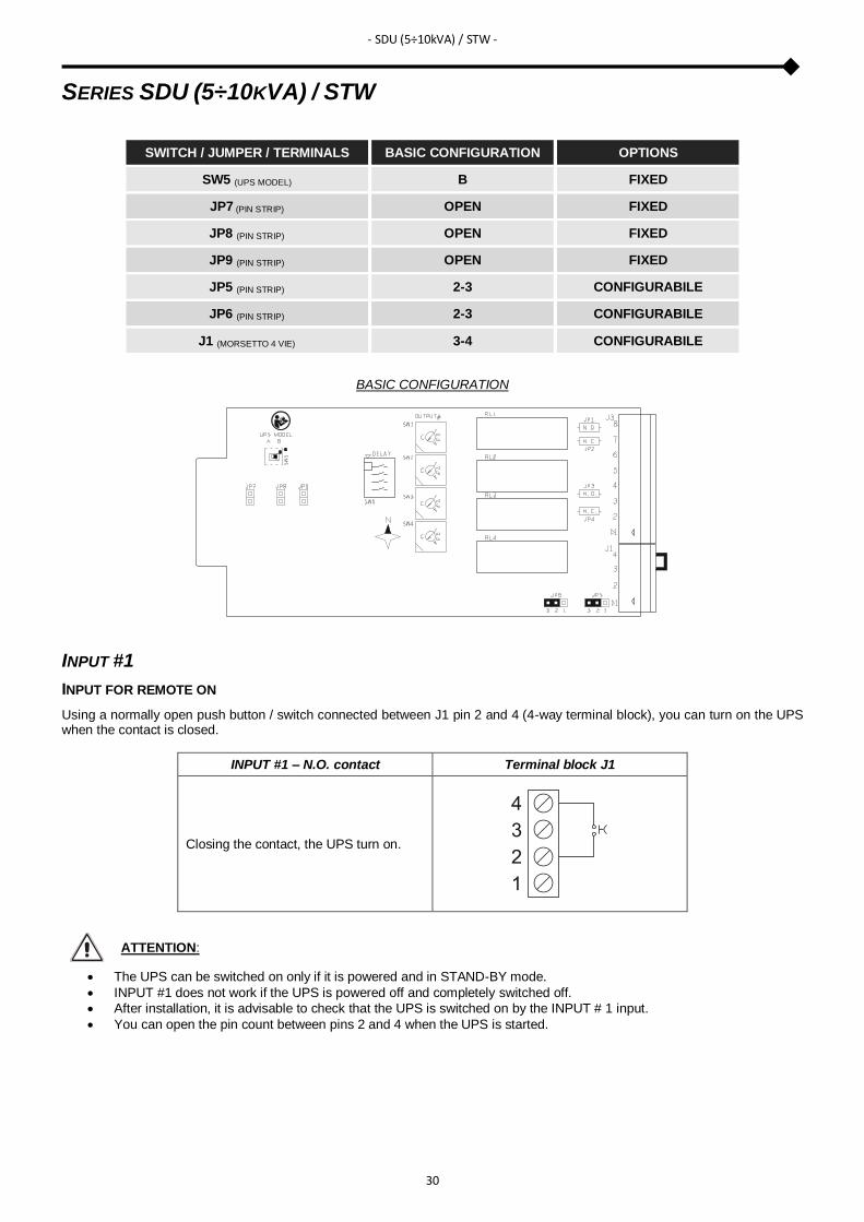
SERIES SDU (5÷10KVA) / STW
SWITCH / JUMPER / TERMINALS BASIC CONFIGURATION OPTIONS
SW5 (UPS MODEL) B FIXED
JP7 (PIN STRIP) OPEN FIXED
JP8 (PIN STRIP) OPEN FIXED
JP9 (PIN STRIP) OPEN FIXED
JP5 (PIN STRIP) 2-3 CONFIGURABILE
JP6 (PIN STRIP) 2-3 CONFIGURABILE
J1 (MORSETTO 4 VIE) 3-4 CONFIGURABILE
BASIC CONFIGURATION
INPUT #1
INPUT FOR REMOTE ON
Using a normally open push button / switch connected between J1 pin 2 and 4 (4-way terminal block), you can turn on the UPS when the contact is closed.
INPUT #1 – N.O. contact Terminal block J1
Closing the contact, the UPS turn on.
ATTENTION:
• The UPS can be switched on only if it is powered and in STAND-BY mode.
• INPUT #1 does not work if the UPS is powered off and completely switched off.
• After installation, it is advisable to check that the UPS is switched on by the INPUT # 1 input.
• You can open the pin count between pins 2 and 4 when the UPS is started.

- SDU (5÷10kVA) / STW -
31
INPUT #2
INPUT FOR REMOTE OFF
You can manage INPUT #2 input either with a N.C contact than with a N.O. contact.
INPUT #2 with N.C. contact
Card configuration:
• Insert the jumper between pins 2 and 3 of JP6 (3-pin strip pins on the card) Using a normally closed push button / switch, connected between pin 3 and pin 4 of J1 (4-way terminal block), you can turn off the UPS when the contact is opened. You can restart the UPS again only after restoring the "normally close" condition of the contact.
INPUT #2 - N.C. contact Position of the jumper on JP6 Terminal block J1
Opening the contact, the UPS turn off.
Pin 2-3 on JP6
INPUT #2 with N.O. contact
Card configuration:
• Insert the jumper between pins 2 and 3 of JP6 (3-pin strip pins on the card) Using a normally open push button / switch, connected between pin 3 and pin 4 of J1 (4-way terminal block), you can turn off the UPS when the contact is closed. You can restart the UPS again only after restoring the "normally open" condition of the contact.
INPUT #2 - N.O. contact Position of the jumper on JP6 Terminal block J1
Closing the contact, the UPS turn off.
Pin 1-2 on JP6
ATTENTION:
• Setting INPUT #2 with N.C. contact, removing the jumper or 4-pole connector, if the UPS is turned on, it will switch off.
• Setting INPUT #2 with N.C. contact, inserting the MultiCOM 384 card into the SLOT without the jumper on the J1 connector on the card, the UPS will switch off instantly.
• INPUT # 2 input does not replace R.E.P.O. contact of the UPS, but is an additional one, so for the UPS to work properly, do not remove the R.E.P.O. contact located on the back of the UPS.

- SDU (5÷10kVA) / STW -
32
INPUT #3
CONFIGURABLE INPUT
Card Configuration:
• Insert jumper between pins 1 and 2 of JP5 (3-pin strip pins on the card) Using a normally closed push button / switch, connected between pin 1 and pin 4 of J1 (4-way terminal block), you can activate the function associated with the INPUT # 3 when the contact is opened. The function associated with INPUT # 3 can be configured via the configuration software (default: Load on bypass). The function remains active as long as the contact remains open.
INPUT #3 – N.C. contact Position of the jumper on JP5 Terminal block J1
Opening the contact, the configured function is activated
Pin 1-2 on JP5
ATTENTION:
• Load on bypass: opening the contact the load power passes from inverter to bypass. With the contact open, the UPS remains in bypass operation even if the input mains is missing. If the contact is closed in the mains present condition, the UPS resumes running from inverter. If the contact is closed in a power failure condition, the UPS resumes from battery operation.
• Pay attention to the correct configuration of the JP5 jumper when connecting a jumper between pins 1 and 4 on the J1 connector. The contact closure shortcut the two pins.
• After installation, it is recommended to check the correct function of the configured function.
Isolated auxiliary power supply + 12Vdc
Card configuration:
• Insert jumper between pin 2 and 3 of JP5 (3-pin strip pins on the card) Modifying the jumper position on the JP5 pin strip, you can get a +12Vdc isolated auxiliary power instead of INPUT #3, useful for powering small devices such as optocouplers needed to send clean contacts to the UPS.
Isolated aux. power Position of the jumper on JP5 Terminal block J1
+12Vdc ±10% 100mA
Pin 2-3 on JP5
ATTENTION:
• Pins 1 and 4 deliver a maximum of 100mA.
• The supplied voltage is 12Vdc ± 10%.
• An absorption greater than the indicated value, or a short circuit, causes a bad or a not functioning of INPUT #1 and INPUT #2.

- SDU (5÷10kVA) / STW -
33
OUTPUT CONTACTS CONFIGURATION
OUTPUT DEFAULT CONFIGURABLE
OUTPUT #1 BATTERY LOW YES
OUTPUT #2 BATTERY WORKING YES
OUTPUT #3 INVERTER LOCKED YES
OUTPUT #4 LOAD ON BYPASS YES
NOTE: the configuration software screen is for illustrative purposes. It may vary according to the UPS series and the software version.
- SPH -
34
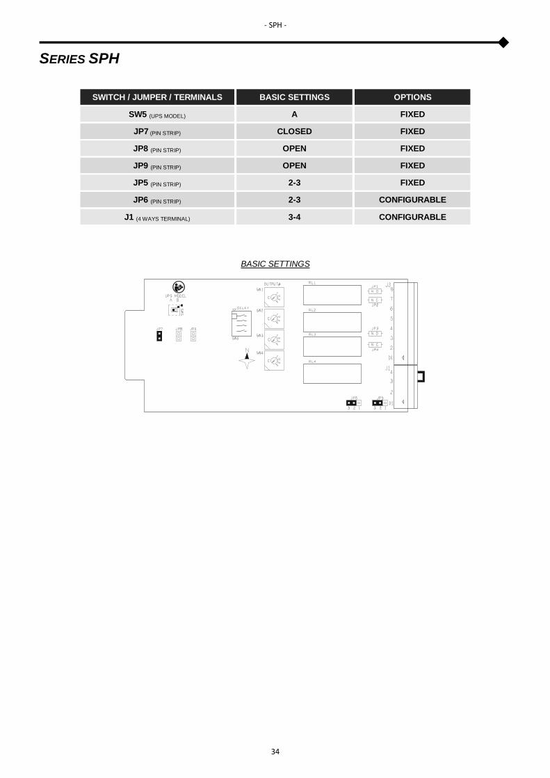
SERIES SPH
SWITCH / JUMPER / TERMINALS BASIC SETTINGS OPTIONS
SW5 (UPS MODEL) A FIXED
JP7 (PIN STRIP) CLOSED FIXED
JP8 (PIN STRIP) OPEN FIXED
JP9 (PIN STRIP) OPEN FIXED
JP5 (PIN STRIP) 2-3 FIXED
JP6 (PIN STRIP) 2-3 CONFIGURABLE
J1 (4 WAYS TERMINAL) 3-4 CONFIGURABLE
BASIC SETTINGS

- SPH -
35
INPUT #1
CONFIGURABLE INPUT
You can assign different functions to the INPUT #1via the UPS configuration software. The default configuration for INPUT #1 is NO FUNCTION (input disabled). Possible configurations are:
• No function
• Remote on
• Remote off
• Remote on/off Using a normally open push button / switch connected between pin 2 and 4 of J1 (4-way terminal block), you can activate the function associated with INPUT #1 when the contact is closed.
INPUT #1 – N.O. contact Terminal block J1
Closing the contact, the UPS activates the function associated to INPUT #1
ATTENTION:
• INPUT #1 does not work if the UPS is powered off and completely switched off.
• After installation, it is advisable to check that the UPS is switched on by the INPUT # 1 input.
• With REMOTE ON, you can open the pin count between pins 2 and 4 when the UPS is started
INPUT #2
CONFIGURABLE INPUT
You can assign different functions to the INPUT #2 via the UPS configuration software. The default configuration for INPUT #2 is NO FUNCTION (input disabled). Possible configurations are:
• No function
• Remote on
• Remote off
• Remote on/off On the MultiCOM 384 card you can manage INPUT #2 input either with a N.C contact than with a N.O. contact.
INPUT #2 with N.C. contact
Card configuration:
• Insert the jumper between pins 2 and 3 of JP6 (3-pin strip pins on the card). Using a normally closed push button / switch, connected between pin 3 and pin 4 of J1 (4-way terminal block), you can turn on or off the UPS (depending on the set configuration) when the contact is opened.
INPUT #2 - N.C. contact Position of the jumper on JP6 Terminal block J1
Opening the contact, the UPS activates the function associated to INPUT #2
Pin 2-3 on JP6

- SPH -
36
INPUT #2 with N.O. contact
Card configuration:
• Insert the jumper between pins 1 and 2 of JP6 (3-pin strip pins on the card) Using a normally open push button / switch, connected between pin 3 and pin 4 of J1 (4-way terminal block), you can turn on or off the UPS (depending on the set configuration) when the contact is closed.
INPUT #2 - N.O. contact Position of the jumper on JP6 Terminal block J1
Closing the contact, the UPS activates the function associated to INPUT #2
Pin 1-2 on JP6
ATTENTION:
• Setting INPUT #2 with N.C. contact, removing the jumper or 4-pole connector, if the UPS is turned on, it will switch off.
• If you insert the MultiCOM 384 card into the SLOT without the jumper on the J1 connector on the card, the UPS will switch off instantly.
• The shutdown command is an immediate REMOTE OFF command and does not remain in memory in the UPS, so you can restart the UPS again without restoring the original status of the contact.
• INPUT #2 does not replace R.E.P.O. contact of the UPS, but is an additional one, so for the UPS to work properly, do not remove the R.E.P.O. contact located on the back of the UPS.
INPUT #3
The MultiCOM 384 board does not handle the INPUT #3 in the SPH series.
Isolated auxiliary power supply + 12Vdc
Card configuration:
• Insert jumper between pin 2 and 3 of JP5 (3-pin strip pins on the card) Modifying the jumper position on the JP5 pin strip, you can get a +12Vdc isolated auxiliary power instead of INPUT #3, useful for powering small devices such as optocouplers needed to send clean contacts to the UPS.
Isolated aux. power Position of the jumper on JP5 Terminal block J1
+12Vdc ±10% 100mA
Pin 2-3 on JP5
ATTENTION:
• Pins 1 and 4 deliver a maximum of 100mA. • The supplied voltage is 12Vdc ± 10%.
• An absorption greater than the indicated value, or a short circuit, causes an immediate UPS shutdown due the failure of power supply for INPUT #1 and INPUT #2 inputs (configurable as REMOTE OFF).

- SPH -
37
OUTPUT CONTACTS CONFIGURATION
OUTPUT DEFAULT CONFIGURABLE
OUTPUT #1 BATTERY LOW YES
OUTPUT #2 BATTERY WORKING YES
OUTPUT #3 INVERTER LOCKED YES
OUTPUT #4 OUTPUT POWERED YES
ATTENTION: by default the OUTPUT #4 is associated to OUTPUT POWERED function.
NOTE: the configuration software screen is for illustrative purposes. It may vary according to the UPS series and the software version.

- MST / MSM / MCT / C1T / C1M / GMI -
38
SERIES MST / MSM / MCT / MCM / C1T / C1M / GMI
SWITCH / JUMPER / TERMINALS BASIC SETTINGS OPTIONS
SW5 (UPS MODEL) A FIXED
JP7 (PIN STRIP) OPEN FIXED
JP8 (PIN STRIP) OPEN FIXED
JP9 (PIN STRIP) OPEN FIXED
JP5 (PIN STRIP) 2-3 CONFIGURABLE
JP6 (PIN STRIP) OPEN FIXED
J1 (4 WAYS TERMINAL) 3-4 FIXED
BASIC SETTINGS
INPUT #1
INPUT FOR REMOTE ON
Using a normally open push button / switch connected between pin 2 and 4 of J1 (4-way terminal block), you can turn on the UPS when the contact is closed.
INPUT #1 – N.O. contact Terminal block J1
Closing the contact the UPS turn on.
ATTENTION:
• The UPS can be switched on only if it is powered and in STAND-BY mode.
• INPUT #1 does not work if the UPS is powered off and completely switched off.
• After installation, it is advisable to check that the UPS is switched on by the INPUT # 1 input.
• You can open the pin count between pins 2 and 4 when the UPS is started.

- MST / MSM / MCT / C1T / C1M / GMI -
39
INPUT #2
The MultiCOM 384 board does not handle the INPUT #2 in the series MST / MSM / MCT / MCM / C1T / C1M / GMI.
INPUT #3
CONFIGURABLE INPUT
Card Configuration:
• Insert jumper between pins 1 and 2 of JP5 (3-pin strip pins on the card) Using a normally closed push button / switch, connected between pin 1 and pin 4 of J1 (4-way terminal block), you can activate the function associated with the INPUT #3 when the contact is opened. The function associated with INPUT # 3 can be configured via the configuration software (default: Load on bypass). The function remains active as long as the contact remains open.
INPUT #3 – N.C. contact Position of the jumper on JP5 Terminal block J1
Opening the contact, the configured function is activated.
Pin 1-2 on JP5
ATTENTION:
• Load on bypass: opening the contact the load power passes from inverter to bypass. With the contact open, the UPS remains in bypass operation even if the input mains is missing. If the contact is closed in the mains present condition, the UPS resumes running from inverters. If the contact is closed in a power failure condition, the UPS resumes from battery operation.
• Pay attention to the correct configuration of the JP5 jumper when connecting a jumper between pins 1 and 4 on the J1 connector. The contact closure shortcut the two pins.
• After installation, it is recommended to check the correct function of the configured function.
Isolated auxiliary power supply + 12Vdc
Card configuration:
• Insert jumper between pin 2 and 3 of JP5 (3-pin strip pins on the card) Modifying the jumper position on the JP5 pin strip, you can get a +12Vdc isolated auxiliary power instead of INPUT #3, useful for powering small devices such as optocouplers needed to send clean contacts to the UPS.
Isolated aux. power Position of the jumper on JP5 Terminal block J1
+12Vdc ±10% 100mA
Pin 2-3 on JP5
ATTENTION:
• Pins 1 and 4 deliver a maximum of 100mA.
• The supplied voltage is 12Vdc ± 10%.

- MST / MSM / MCT / C1T / C1M / GMI -
40
OUTPUT CONTACTS CONFIGURATION
OUTPUT DEFAULT CONFIGURABLE
OUTPUT #1 BATTERY LOW YES
OUTPUT #2 BATTERY WORKING YES
OUTPUT #3 INVERTER LOCKED YES
OUTPUT #4 LOAD ON BYPASS YES
NOTE: the configuration software screen is for illustrative purposes. It may vary according to the UPS series and the software version.

- S3T / S3M / S3U -
41
SERIES S3T / S3M / S3U
SWITCH / JUMPER / TERMINALS BASIC SETTINGS OPTIONS
SW5 (UPS MODEL) A FIXED
JP7 (PIN STRIP) OPEN FIXED
JP8 (PIN STRIP) OPEN FIXED
JP9 (PIN STRIP) OPEN FIXED
JP5 (PIN STRIP) 1-2 CONFIGURABLE
JP6 (PIN STRIP) OPEN FIXED
BASIC SETTINGS
Isolated auxiliary power supply + 12Vdc
Modifying the jumper position on the JP5 pin strip, you can get a +12Vdc isolated auxiliary power instead of INPUT #3, useful for powering small devices such as optocouplers needed to send clean contacts to the UPS.
Isolated aux. power Position of the jumper on JP5 Terminal block J1
+12Vdc ±10% 100mA
Pin 2-3 on JP5
ATTENTION:
• Pins 1 and 4 deliver a maximum of 100mA.
• The supplied voltage is 12Vdc ± 10%.

- S3T / S3M / S3U -
42
By default no function is associated to input/output and they have to be configured via the UPS configuration software. Before setting the input/output, you must select MC384 (MultiCOM 384) for Communication slot 2.
- S3T / S3M / S3U -
43
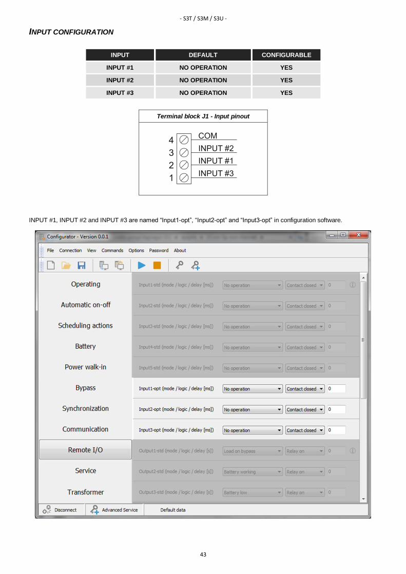
INPUT CONFIGURATION
INPUT DEFAULT CONFIGURABLE
INPUT #1 NO OPERATION YES
INPUT #2 NO OPERATION YES
INPUT #3 NO OPERATION YES
Terminal block J1 - Input pinout
INPUT #1, INPUT #2 and INPUT #3 are named “Input1-opt”, “Input2-opt” and “Input3-opt” in configuration software.
- S3T / S3M / S3U -
44
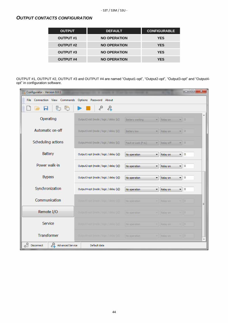
OUTPUT CONTACTS CONFIGURATION
OUTPUT DEFAULT CONFIGURABLE
OUTPUT #1 NO OPERATION YES
OUTPUT #2 NO OPERATION YES
OUTPUT #3 NO OPERATION YES
OUTPUT #4 NO OPERATION YES
OUTPUT #1, OUTPUT #2, OUTPUT #3 and OUTPUT #4 are named “Output1-opt”, “Output2-opt”, “Output3-opt” and “Output4-opt” in configuration software.
- MPW / MPX -
45
SERIES MPW / MPX
INPUT CONFIGURATION
Inputs that are configurable via software are as follows:
• INPUT #1
• INPUT #2
• INPUT #3
OUTPUT CONTACTS CONFIGURATION
Outputs that are configurable via software are as follows:
• OUTPUT #1
• OUTPUT #2
• OUTPUT #3
• OUTPUT #4
NOTE: refer to the MPW / MPX Advanced configuration manual for features and configuration of the MultiCOM 384.


0MNACCC00ENUF