Introduction of TG3c channel model and beyond
23
doc.: IEEE 802.11-09/0375r1 Submission Slide 1 <Hirokazu Sawada>, <NICT> Date: 2009-03-11 Name Company Address Phone Email Hirokazu Sawada NICT 3-4, Hikarino-oka, Yokosuka, 239-0847, Japan [email protected] Katsuyoshi Sato NICT -- [email protected] Hiroshi Harada NICT -- [email protected] Ryuhei Funada NICT -- [email protected] Chin-Sean Sum NICT -- [email protected] Tuncer Baykas NICT -- [email protected]. jp Junyi Wang NICT -- [email protected] Mohammad Azizur Rahman NICT -- [email protected] Shuzo Kato NICT -- [email protected] Introduction of TG3c channel model and beyond < Mar. 11, 2009 > Authors:
Transcript of Introduction of TG3c channel model and beyond

doc.: IEEE 802.11-09/0375r1
Submission Slide 1 <Hirokazu Sawada>, <NICT>
Date: 2009-03-11
Name Company Address Phone Email
Hirokazu Sawada NICT 3-4, Hikarino-oka, Yokosuka, 239-0847, Japan
Katsuyoshi Sato NICT -- [email protected]
Hiroshi Harada NICT -- [email protected]
Ryuhei Funada NICT -- [email protected]
Chin-Sean Sum NICT -- [email protected]
Tuncer Baykas NICT -- [email protected]
Junyi Wang NICT -- [email protected]
Mohammad Azizur Rahman
NICT -- [email protected]
Shuzo Kato NICT -- [email protected]
Introduction of TG3c channel model and beyond
< Mar. 11, 2009 >
Authors:
doc.: IEEE 802.11-09/0375r1
Submission
< Mar. 11, 2009 >
<Hirokazu Sawada>, <NICT>Slide 2
OutlineIntroduction of TG3c channel modelComments on TGad channel model requirements (P802.11-09/323r0)Comments on channel models for 60 GHz WLAN systems (P802.11-09/336r0)Reusability of TG3c intra-cluster parametersIntroduction of recent propagation measurement

doc.: IEEE 802.11-09/0375r1
Submission
< Mar. 11, 2009 >
<Hirokazu Sawada>, <NICT>Slide 3
Introduction of TG3c channel model (1)
TG3c channel model is statistical channel modelThe model merging statistical two-path and SV-modelAoA, ToA at Rx side were included, however, AoD at Tx-side was not adopted, good enough for non-beam forming systemsLine of sight component is very strong comparing with non-line of sight components
doc.: IEEE 802.11-09/0375r1
Submission
< Mar. 11, 2009 >
<Hirokazu Sawada>, <NICT>Slide 4
Introduction of TG3c channel model (2)
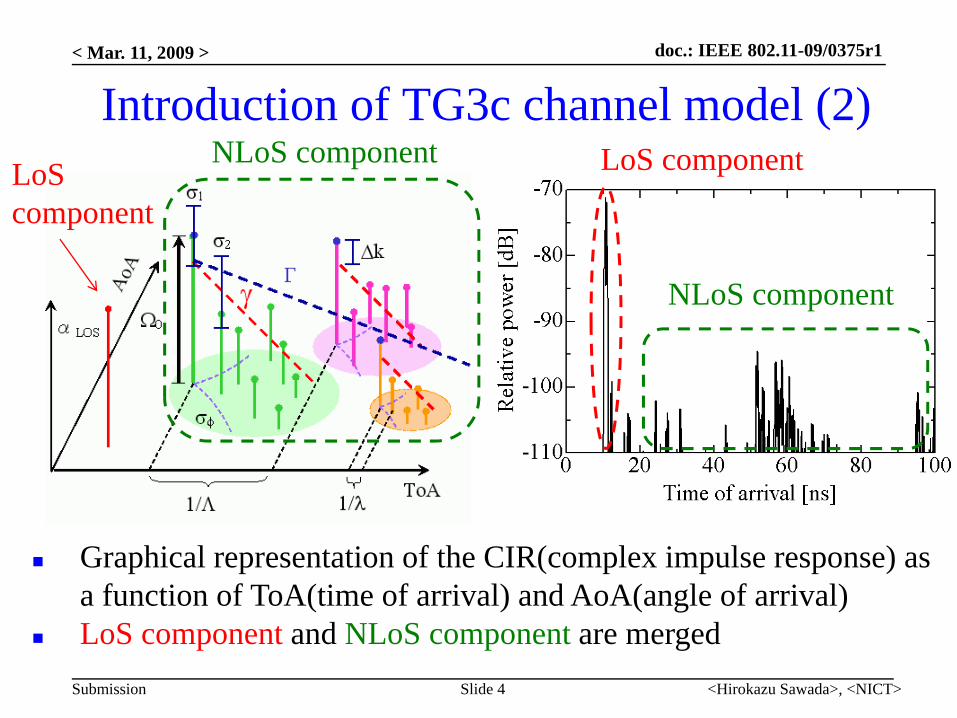
Graphical representation of the CIR(complex impulse response) as a function of ToA(time of arrival) and AoA(angle of arrival)LoS component and NLoS component are merged
LoScomponent
LoS component
NLoS component
NLoS component
doc.: IEEE 802.11-09/0375r1
Submission
For NLoS environmentNLoS channel models for “ Desk top” and “ Residential” were developed By removing LoS component from LOS channel models to save channel model development timeA number of measurements carried out for real NLOS environments later on and confirmed this “short-cut” approach is good enough
< Mar. 11, 2009 >
Slide 5 <Hirokazu Sawada>, <NICT>

doc.: IEEE 802.11-09/0375r1
Submission
Channel Model Scenario Environment Descriptions
CM1 LOS ResidentialTypical home with multiple rooms and furnished with furniture, TV setslounges, etc. The size is comparable to the small office room. The walls/floorare made of concrete or wood covered by wallpaper/carpet. There are alsowindows and wooden door in different rooms within the residentialenvironment.
CM2 NLOS
CM3 LOS OfficeTypical office setup furnished with multiple chairs, desks, computers andwork stations. Bookshelves, cupboards and whiteboards are also interspersedwithin the environment. The walls are made by metal or concrete covered byplasterboard or carpet with windows and door on at least one side of theoffice. Cubical, laboratory, open and closed office can be treated as a genericoffice. Typically these offices are linked by long corridors.CM4 NLOS
CM5 LOS LibraryTypical small size library with multiple desks, chairs and metal bookshelves.Bookshelves are filled with books, magazines, etc. Some tables and chairswere interspersed between the bookshelves. At least one side of room haswindows and/or door. The walls are made of concrete.
CM6 NLOS
CM7 LOS DesktopTypical office desktop and computer clutter. Partitioning surrounded thisenvironment
CM8 NLOSCM9 LOS Kiosk Typical kiosk server with human body holding a portable device. The portable
device is pointed to the kiosk server.
< Mar. 11, 2009 >
<Hirokazu Sawada>, <NICT>Slide 6
Introduction of TG3c channel model (3)
by NICT contributions

doc.: IEEE 802.11-09/0375r1
Submission
Comments on TGad channel model requirements (P802.11-09/323r0)
< Mar. 11, 2009 >
<Hirokazu Sawada>, <NICT>Slide 7

doc.: IEEE 802.11-09/0375r1
Submission
< Mar. 11, 2009 >
<Hirokazu Sawada>, <NICT>Slide 8
802.15.3c Channel Model Discussion (1)• We believe the general approach used to create the channel
models, based on the extended time-angular S-V model, is valid. Some of results obtained by the IEEE 802.15.3c channel modeling group may be reused in the 60 GHz TGad channel model.
• Yes: By reusing the TG3c channel model parameter will reduce the measurement time for development of TGad channel model
• However, the reuse of the IEEE 802.15.3c channel modeling results is complicated by the fact that no raw channel measurement data, except for the IMST company data used to generate the library model, are available [2].
• No: NICT provided raw channel data for LoS residential and NLoS office environment. There are on IEEE server. Document numbers are 802.15-06/12r1 and 06/13r2

doc.: IEEE 802.11-09/0375r1
Submission
< Mar. 11, 2009 >
<Hirokazu Sawada>, <NICT>Slide 9
802.15.3c Channel Model Discussion (2)
• 802.15.3c channel model provides limited support forevaluating beamforming performance:– Angle-of-Departure (AoD) is not included in the .15.3c channel models
and the AoA model only describes the azimuth angle (no elevationinformation)
• TG3c channel model developments focused on not so high gainantenna systems and resulted in relevant channel models forlow to medium gain antenna systems. The channel modeldevelopments on high gain antenna systems such as thesystems deploying beam forming technology may result in achannel model close to AWGN.

doc.: IEEE 802.11-09/0375r1
Submission
< Mar. 11, 2009 >
<Hirokazu Sawada>, <NICT>Slide 10
802.15.3c Channel Model Discussion (2)• There is no support for polarization characteristics:
– As was shown in [3], the degradation due to polarization mismatch can beas high as 20 dB
• Only vertical polarization was adopted for TG3c channel models, since reflection waves from floor and ceiling are reduced with vertical polarization. If the polarization is taken into account, it is difficult to keep the independence of room since reflection coefficient depends on incident angle.
• There is no support for non-stationary, human body blockage effects which can have a strong impact on 60 GHz devices
• A loss of human body blockage over 40dB has been confirmed by experiments, it can be dealt as NLoS environment or by reducing the number of clusters.

doc.: IEEE 802.11-09/0375r1
Submission
< Mar. 11, 2009 >
<Hirokazu Sawada>, <NICT>Slide 11
802.15.3c Channel Model Discussion (3)
• Due to differences in the approaches to statistical channelmodeling, 802.15.3c decided to prepare golden data sets(instead of Matlab code) for the channel realizations that wereused in proposal evaluation.
• No. TG3c Matlab code was provided to generate wholechannel realizations. Golden data sets were also provided fornon-Matlab users for easy simulation.

doc.: IEEE 802.11-09/0375r1
Submission
< Mar. 11, 2009 >
<Hirokazu Sawada>, <NICT>Slide 12
802.15.3c Channel Model Discussion (3)• The golden sets were prepared for only a subset of the channel
models (CM1, CM2 and CM3) that included some“extraordinary” realizations that produced a BER “floor” forsome channels [4, 5].
• The Golden sets were prepared for all channel models requiredfor system simulation and they are not only a subset.Extraordinary responses are fatal problem of statistical channelmodels (modified S-V). Thus 10% worst responses wereremoved from PHY simulations in 15.3c as well as 15.4a. NICTproposed an improvement method to solve this problem(Doc.P802.15-06-0453r0), however, it was withdrawn due to thelimited time line for “call for proposal”.

doc.: IEEE 802.11-09/0375r1
Submission
< Mar. 11, 2009 >
<Hirokazu Sawada>, <NICT>Slide 13
Propagation Environments of Interest for TGad
• Three environments are considered in accordance with theevaluation methodology proposal [6]:– Residential living room– Conference room– Cubicle environment
• The residential environment was measured. The parameters ofTG3c desktop environments can be used as another measurementdata of conference room environment for TGad. Newmeasurement only for cubicle environment will be required.

doc.: IEEE 802.11-09/0375r1
Submission
< Mar. 11, 2009 >
<Hirokazu Sawada>, <NICT>Slide 14
Propagation Environments of Interest for TGad
• Adding more environments may unnecessarily complicate thechannel model development:– Most of the TGad usage models [7] can be related to the above three
environments– Measurements may not be available for other environments
• If other environments are required for new usage, TG3c channelmodels have possibility to support them.

doc.: IEEE 802.11-09/0375r1
Submission
< Mar. 11, 2009 >
<Hirokazu Sawada>, <NICT>Slide 15
Comments channel models for 60 GHz WLAN systems (P802.11-09/336r0)( ) ( )
( ) ( ) ( ) ( ) ( ) ( )∑
∑−−−−−=
Θ−Φ−Θ−Φ−−=
k
kirxrx
kirxrx
kitxtx
kitxtx
kikirxrxtxtx
i
i
irxrx
irxrx
itxtx
itxtx
iiirxrxtxtx
ttC
TtCAth
),(),(),(),(),(),()(
)()()()()()()(
,,,,
,,,,,,,,
θθδϕϕδθθδϕϕδτδαθϕθϕ
θϕθϕθϕθϕ
Tx Rx
1st order reflection from ceiling
1st order reflection from wall
2nd order reflection from walls
LOS
3 m
3 m
1 m
1 m
4.5 m
Ray Tracing Model for Conference Room1
m

doc.: IEEE 802.11-09/0375r1
Submission
< Mar. 11, 2009 >
<Hirokazu Sawada>, <NICT>Slide 16
Comments on channel models for 60 GHz WLAN systems (P802.11-09/336r0)Direct wave is considered as a separated component from other clusters of reflection wavesCluster parameters (large scale parameter) are simulated by ray trace methodThat is a good idea to reduce the measurement time for three dimensional AoD and AoA informationOnly intra-cluster parameter is extracted from measurement resultA channel model of conference environment is proposed

doc.: IEEE 802.11-09/0375r1
Submission
< Mar. 11, 2009 >
<Hirokazu Sawada>, <NICT>Slide 17
Reusability of intra-cluster parameter
TG3c channel model has intra-cluster parameters in many environments
By reusing these parameters, the measurement time will be reduced
λ, intra-cluster (ray) arrival rateγ, intra-cluster (ray) decay rateσr, ray lognormal standard deviationσφ, angle spread
doc.: IEEE 802.11-09/0375r1
Submission
Summary
TG3c channel model is introduced for development of TGad channel modelTo reuse TG3c intra-cluster parameter is proposed to reduce new measurement
< Mar. 11, 2009 >
<Hirokazu Sawada>, <NICT>Slide 18
doc.: IEEE 802.11-09/0375r1
Submission
Discussion
How to compromise Ray tracing as a good propagation analysis tool and modified S-V model for easy system simulationHow to reuse existing data including TG3c intra-cluster parametersHow to validate developed channel models (RMS delay spread, Excess delay, etc.)
< Mar. 11, 2009 >
<Hirokazu Sawada>, <NICT>Slide 19
doc.: IEEE 802.11-09/0375r1
Submission
< Mar. 11, 2009 >
<Hirokazu Sawada>, <NICT>Slide 20
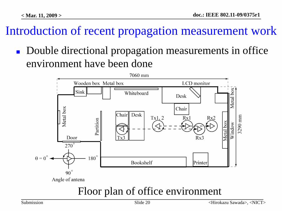
Introduction of recent propagation measurement workDouble directional propagation measurements in office environment have been done
Floor plan of office environment

doc.: IEEE 802.11-09/0375r1
Submission
< Mar. 11, 2009 >
<Hirokazu Sawada>, <NICT>Slide 21
Detail of propagation measurementInstrument HP8510C VNACenter frequency 62.5 GHzBandwidth 3 GHz
Tx and Rx antennas Conical horn antenna (16dBi)Beam width: 30 degrees
Rotational step angle 5 degreesDistance between Tx and Rx d =1, 2, 3m

doc.: IEEE 802.11-09/0375r1
Submission
< Mar. 11, 2009 >
<Hirokazu Sawada>, <NICT>Slide 22
Example of measurement results (distance:3m)
Averaged relative received power Delay spreadDirect waveReflection wave clusters

doc.: IEEE 802.11-09/0375r1
Submission
< Mar. 11, 2009 >
<Hirokazu Sawada>, <NICT>Slide 23
Statistics of measurement results example
Averaged relative received power Delay spread
Development of double directional channel model from measurement result is future work