Introduction of PC138US and PC128US-8 Hydraulic Excavators · Introduction of Product Introduction...
7
Introduction of Product Introduction of PC138US and PC128US-8 Hydraulic Excavators Youjirou Ohbatake Masami Naruse New hydraulic excavators, models PC138US and PC128US-8, have been developed and introduced into the market based on the Komatsu concepts of “environment,” “safety” and “IT.” The background to the development and its technology are described, and the new products are also de- scribed. Key Words: hydraulic excavator, tail swing minimal radius vehicle, PC138US, TIER3, domestic super low noise, EOPS 1. Introduction Since the market entry of its model 2 in 1999, the PC138US and PC128US (hereinafter “PC138US”) have re- sponded to a variety of market demands as the core models of Komatsu’s tail swing minimal radius hydraulic excavators. Recently, demands for a reduction in the environmental load are becoming increasingly more rigorous. Against this backdrop, since 2006, new-tier exhausted gas regulations have been enforced successively in Japan, the United States and Europe. The EU has already implemented Tier-2 noise regulation beginning 2006. The PC138US-8 com- plying with the regulations and featuring various selling points based on Komatsu’s concepts of “environment,” “safety” and “IT” has introduced into the market. The PC138US-8 is described in the following. (Fig. 1 and Photo 1) Short-tail Swing Radius Excavator making continual progress Photo 1 PC138US-8 2. Objective of Development Perceiving future of hydraulic excavators Environment, safety and IT of higher dimen- sions pursued through the highest “quality and reliability” that are the pride of KOMATSU Environment (Ecology & Economy) Compliance to Tier-3 exhausted gas regula- tions. Super low noise regulation of Land, Infra- structure and Transport Ministry of Japan cleared. To develop a hydraulic excavator that complies with the environmental regulations, reduces the environmental load, pursues comfort, enhances utilization of IT and maintainabil- ity and upgrades its product power based on the concepts of “environment,” “safety” and “IT” and meeting user needs. Safety (Safety & COMFORT) New, large US cab - Ample space around feet, 10% increase in volume inside cab Operator protected by rugged cab meeting safety standards (EOPS) of the highest level Quiet cab featuring lowest noise level in industry, noise level further lowered and operator fatigue mitigated IT IT technology, leader in industry, further upgraded The upgraded KOMTRAX and multi-monitor screen further enhance ease of operation for higher safety and reliability 1) Compliance with environmental regulations • Compliance with next-tier exhausted gas regulations of Japan, the United States and Europe Fig. 1 Development concepts • Display of guidance messages prompting energy saving drive on the monitor panel Eco gauge Idling stop caution 2006 ② VOL. 52 NO.158 Introduction of PC138US and PC128US-8 Hydraulic Excavators ― 1 ―
Transcript of Introduction of PC138US and PC128US-8 Hydraulic Excavators · Introduction of Product Introduction...
Introduction of Product
Introduction of PC138US and PC128US-8 Hydraulic Excavators
Youjirou Ohbatake
Masami Naruse
New hydraulic excavators, models PC138US and PC128US-8, have been developed and introduced into
the market based on the Komatsu concepts of “environment,” “safety” and “IT.” The background to the development and its technology are described, and the new products are also de-
scribed.
Key Words: hydraulic excavator, tail swing minimal radius vehicle, PC138US, TIER3, domestic super low noise, EOPS
1. Introduction
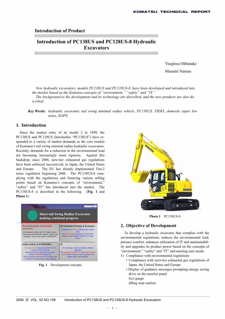
Since the market entry of its model 2 in 1999, the PC138US and PC128US (hereinafter “PC138US”) have re-sponded to a variety of market demands as the core models of Komatsu’s tail swing minimal radius hydraulic excavators. Recently, demands for a reduction in the environmental load are becoming increasingly more rigorous. Against this backdrop, since 2006, new-tier exhausted gas regulations have been enforced successively in Japan, the United States and Europe. The EU has already implemented Tier-2 noise regulation beginning 2006. The PC138US-8 com-plying with the regulations and featuring various selling points based on Komatsu’s concepts of “environment,” “safety” and “IT” has introduced into the market. The PC138US-8 is described in the following. (Fig. 1 and Photo 1)
Short-tail Swing Radius Excavator making continual progress Photo 1 PC138US-8
2. Objective of Development Perceiving future of hydraulic
excavators Environment, safety and IT of higher dimen-
sions pursued through the highest “quality and reliability” that are the pride of KOMATSU
Environment (Ecology & Economy)Compliance to Tier-3 exhausted gas regula-
tions. Super low noise regulation of Land, Infra-structure and Transport Ministry of Japan
cleared.
To develop a hydraulic excavator that complies with the environmental regulations, reduces the environmental load, pursues comfort, enhances utilization of IT and maintainabil-ity and upgrades its product power based on the concepts of “environment,” “safety” and “IT” and meeting user needs.
Safety (Safety & COMFORT) New, large US cab - Ample space around feet, 10%
increase in volume inside cab Operator protected by rugged cab meeting safety
standards (EOPS) of the highest level Quiet cab featuring lowest noise level in industry, noise
level further lowered and operator fatigue mitigated
IT IT technology, leader in industry, further
upgraded The upgraded KOMTRAX and multi-monitor screen further enhance ease of operation for
higher safety and reliability 1) Compliance with environmental regulations • Compliance with next-tier exhausted gas regulations of
Japan, the United States and Europe Fig. 1 Development concepts • Display of guidance messages prompting energy saving
drive on the monitor panel Eco gauge Idling stop caution
2006 ② VOL. 52 NO.158 Introduction of PC138US and PC128US-8 Hydraulic Excavators
― 1 ―
• Reduction of ambient noise Compliance with super low noise regulation of Land, Infrastructure and Transport Ministry of Japan Compliance with EU Tier-2 noise regulation
2) Safety and comfort To develop hydraulic excavators as global machines clearing stricter safety standards of the world and pursu-ing safety and comfort. The following features should be incorporated to accomplish this: • Large comfortable cab of new design with a structure
to protect the operator during tipping. • New anti-slip floor plates • Large side and forward mirrors
(Compliance with new ISO standard) • Rearview monitoring system installed as a standard
provision • Low noise inside the cab
3) IT To provide a “better view,” “easier usage” and “more in-formation” by further advancing the IT technology. • New large color liquid crystal multi monitor screen • Function switches • Air conditioner switches and displays included in the
monitor panel • Upgrading of KOMTRAX functions
4) Enhanced work performance The work efficiency and work capacity have been en-hanced further through the adoption of a new hydraulic system and integrated control of the engine and hydraulic power • Travel performance greatly enhanced through a single
pump system of a new double flow type • Turning power during combined operation enhanced
through an increase in the capacity of the turning mo-tor.
5) Enhanced maintainability • Fuel pre-filter with a water separator • Easy cleaning of air cleaner suction inlet
3. Selling Points
Based on the foregoing, the selling points of the PC138US-8 and the technologies required to accomplish them are described.
3.1 Environment 3.1.1 Compliance with Next-tier Emission
Gas Regulations of Japan, the United States and Europe
Compliance with next-tier exhausted gas regulations of Japan, the United States and Europe. The exhausted gas
regulations for the PC138US class in regions and years of enforcement are as follows. (Table 1)
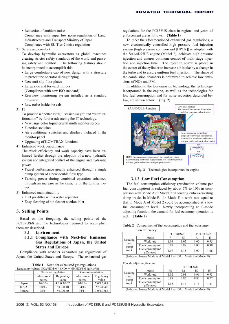
To meet the aforementioned exhausted gas regulations, a new electronically controlled high pressure fuel injection system (high pressure common rail [HPCR]) is adopted with the SAA4D95LE engine (Model 2), achieves high pressure injection and assures optimum control of multi-stage injec-tion and injection time. The injection nozzle is placed in the center of the cylinder to increase air intake by a change in the turbo and to ensure uniform fuel injection. The shape of the combustion chambers is optimized to achieve low emis-sions of NOx and PM.
In addition to the low emission technology, the technology incorporated in the engine, as well as the technologies for low fuel consumption and for noise reduction described be-low, are shown below. (Fig. 2)
• Low noise muffler The internal structure of the muffler is modified to reduce exhaust noise
SAA4D95LE-5 engine
• New combustion technology Shape of combustion chambers is optimized to simultaneously reduce nitrogen oxide and particulate matter
• HPCR (high pressure common rail) fuel injection system Electronically controlled high pressure fuel injection purifies exhaust gases and enhances engine performance
Fig. 2 Technologies incorporated in engine
3.1.2 Low Fuel Consumption
The fuel consumption efficiency (production volume per fuel consumption) is reduced by about 5% to 10% in com-parison with Mode A of Model 2 in loading onto excavating dump trucks in Mode P. In Mode F, a work rate equal to that in Mode A of Model 2 could be accomplished at a low fuel consumption level. Newly incorporating an E-mode adjusting function, the demand for fuel economy operation is met. (Table 2)
Table 2 Comparison of fuel consumption and fuel consump-
tion efficiency PC138US-8 PC138US-2
Mode P E0 A E Work rate 1.04 1.02 1.00 0.95
Fuel consumption 0.97 0.89 1.00 0.90
Loading onto dump truck Fuel consumption
efficiency 1.07 1.15 1.00 1.06
(Indicated basing Mode A of Model 2 as 100. Mode P of Model 8)
E mode adjusting function PC138US-8
Mode E0 E1 E2 E3 Work rate 1.02 0.98 0.96 0.93
Fuel consumption 0.89 0.86 0.83 0.77
Loading onto dump truck Fuel consumption
efficiency 1.15 1.14 1.16 1.21
(Indicated basing Mode A of Model 2 as 100. Mode P of Model 8)
2006 ② VOL. 52 NO.158 Introduction of PC138US and PC128US-8 Hydraulic Excavators
― 2 ―
Table 1 Next-tier exhausted gas regulations Regulatory values: NOx/HC/PM * (NOx + NMHC)/PM (g/Kw*h)
Next-tier regulation Current regulation Enforcement
period Regulatory
value Enforcement
period Regulatory
value Japan 08/10~ 4.0/0.7/0.25 03/10~ 7.0/1.3/0.4U.S.A. 08/1~ *4.7/0.40 04/1~ *7.5/0.40 Europe 08/1~ *4.7/0.40 04/1~ 7.0/1.3/0.4
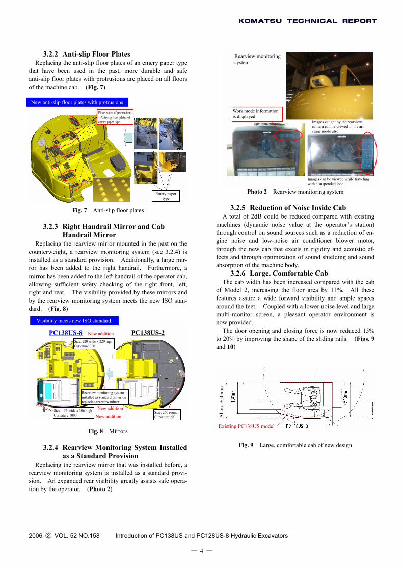
To simultaneously achieve a heat balance and low noise, a side-by-side cooling system with an increase in the cooling capacity is employed. At the same time, the flow of cool-ing air inside the engine hood is improved through comput-erized flow dynamics (CFD) simulation, achieving a tightly sealed hood and supply of a necessary air volume to the cooling core at the same time. A noise absorption braid and resonator are newly installed, reducing fan noise and engine air intake noise. By optimally placing sound-absorbing materials on the machine body, the ambient noise of the ma-chine is reduced. (Fig. 5)
Exhausted gas regulations are met by the engine alone, while fuel consumption is improved. Pressure losses of the hydraulic system are reduced. Matching control of the en-gine and hydraulic pump was optimized by electronic control. The efficiency of hydraulic equipment has been improved also.
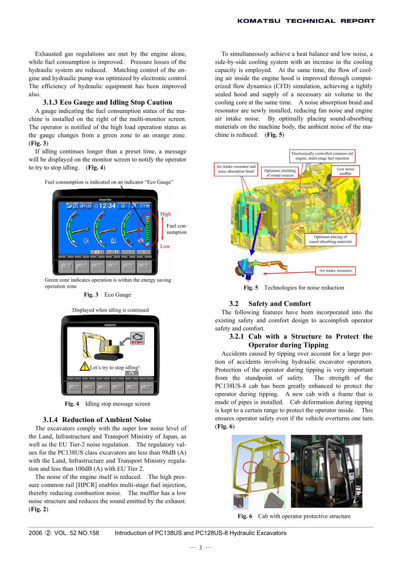
3.1.3 Eco Gauge and Idling Stop Caution A gauge indicating the fuel consumption status of the ma-
chine is installed on the right of the multi-monitor screen. The operator is notified of the high load operation status as the gauge changes from a green zone to an orange zone. (Fig. 3)
If idling continues longer than a preset time, a message will be displayed on the monitor screen to notify the operator to try to stop idling. (Fig. 4)
Electronically controlled common rail engine, multi-stage fuel injection
Air intake resonator and noise absorption braid Low noise
mufflerOptimum shielding
of sound sources Fuel consumption is indicated on an indicator “Eco Gauge”
HHiigghh
Fuel con-sumption
Optimum placing of sound-absorbing materials
LLooww
Air intake resonator
Green zone indicates operation is within the energy savingoperation zone Fig. 5 Technologies for noise reduction
Fig. 3 Eco Gauge 3.2 Safety and Comfort
Displayed when idling is continued The following features have been incorporated into the existing safety and comfort design to accomplish operator safety and comfort.
3.2.1 Cab with a Structure to Protect the Operator during Tipping
Accidents caused by tipping over account for a large por-tion of accidents involving hydraulic excavator operators. Protection of the operator during tipping is very important from the standpoint of safety. The strength of the PC138US-8 cab has been greatly enhanced to protect the operator during tipping. A new cab with a frame that is made of pipes is installed. Cab deformation during tipping is kept to a certain range to protect the operator inside. This ensures operator safety even if the vehicle overturns one turn. (Fig. 6)
Let’s try to stop idling!
Fig. 4 Idling stop message screen
3.1.4 Reduction of Ambient Noise The excavators comply with the super low noise level of
the Land, Infrastructure and Transport Ministry of Japan, as well as the EU Tier-2 noise regulation. The regulatory val-ues for the PC138US class excavators are less than 98dB (A) with the Land, Infrastructure and Transport Ministry regula-tion and less than 100dB (A) with EU Tier 2.
The noise of the engine itself is reduced. The high pres-sure common rail [HPCR] enables multi-stage fuel injection, thereby reducing combustion noise. The muffler has a low noise structure and reduces the sound emitted by the exhaust. (Fig. 2)
2006 ② VOL. 52 NO.158 Introduction of PC138US and PC128US-8 Hydraulic Excavators
― 3 ―
Fig. 6 Cab with operator protective structure
3.2.2 Anti-slip Floor Plates
Rearview monitoring system Replacing the anti-slip floor plates of an emery paper type
that have been used in the past, more durable and safe anti-slip floor plates with protrusions are placed on all floors of the machine cab. (Fig. 7)
New anti-slip floor plates with protrusionsWork mode information is displayed
Floor plates of protrusions + Anti-slip floor plates of emery paper type Images caught by the rearview
camera can be viewed in the arm crane mode also
Images can be viewed while traveling with a suspended load
Photo 2 Rearview monitoring system Emery paper type
3.2.5 Reduction of Noise Inside Cab Fig. 7 Anti-slip floor plates A total of 2dB could be reduced compared with existing
machines (dynamic noise value at the operator’s station) through control on sound sources such as a reduction of en-gine noise and low-noise air conditioner blower motor, through the new cab that excels in rigidity and acoustic ef-fects and through optimization of sound shielding and sound absorption of the machine body.
3.2.3 Right Handrail Mirror and Cab
Handrail Mirror Replacing the rearview mirror mounted in the past on the
counterweight, a rearview monitoring system (see 3.2.4) is installed as a standard provision. Additionally, a large mir-ror has been added to the right handrail. Furthermore, a mirror has been added to the left handrail of the operator cab, allowing sufficient safety checking of the right front, left, right and rear. The visibility provided by these mirrors and by the rearview monitoring system meets the new ISO stan-dard. (Fig. 8)
3.2.6 Large, Comfortable Cab The cab width has been increased compared with the cab
of Model 2, increasing the floor area by 11%. All these features assure a wide forward visibility and ample spaces around the feet. Coupled with a lower noise level and large multi-monitor screen, a pleasant operator environment is now provided.
NNeeww aaddddiittiioonn PC138US-2 PC138US-8 Size: 220 wide x 220 high Curvature 300
Visibility meets new ISO standard.
The door opening and closing force is now reduced 15% to 20% by improving the shape of the sliding rails. (Figs. 9 and 10)
Abo
ut +
50m
m
NNeeww aaddddiittiioonn
NNeeww aaddddiittiioonn
Rearview monitoring system installed as standard provision replacing rearview mirror
Size: 156 wide x 306 high Curvature 1000
Size: 260 round Curvature 200
Existing PC138US model Fig. 8 Mirrors
Fig. 9 Large, comfortable cab of new design 3.2.4 Rearview Monitoring System Installed
as a Standard Provision Replacing the rearview mirror that was installed before, a
rearview monitoring system is installed as a standard provi-sion. An expanded rear visibility greatly assists safe opera-tion by the operator. (Photo 2)
2006 ② VOL. 52 NO.158 Introduction of PC138US and PC128US-8 Hydraulic Excavators
― 4 ―
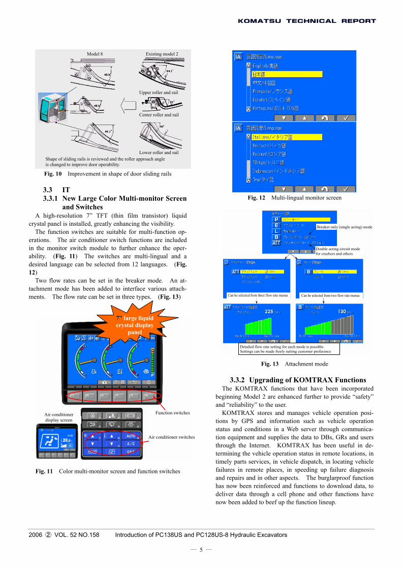
Model 8 Existing model 2
Upper roller and rail
Center roller and rail
Lower roller and rail Shape of sliding rails is reviewed and the roller approach angle is changed to improve door operability.
Fig. 10 Improvement in shape of door sliding rails
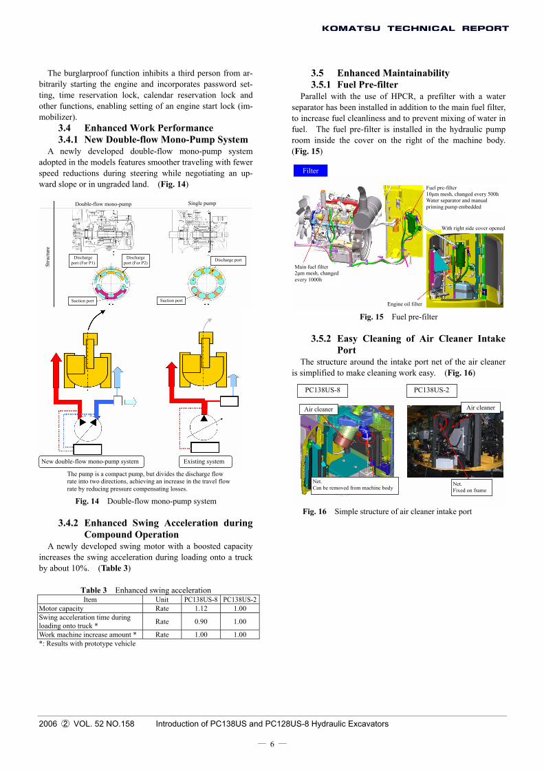
3.3 IT 3.3.1 New Large Color Multi-monitor Screen
and Switches Fig. 12 Multi-lingual monitor screen
A high-resolution 7” TFT (thin film transistor) liquid
crystal panel is installed, greatly enhancing the visibility. Breaker only (single acting) mode The function switches are suitable for multi-function op-
erations. The air conditioner switch functions are included in the monitor switch module to further enhance the oper-ability. (Fig. 11) The switches are multi-lingual and a desired language can be selected from 12 languages. (Fig. 12)
Double acting circuit mode for crushers and others
Two flow rates can be set in the breaker mode. An at-tachment mode has been added to interface various attach-ments. The flow rate can be set in three types. (Fig. 13) Can be selected from three flow rate menus Can be selected from two flow rate menus
77”” large liquid crystal display
panel
3.3.
The Kbeginningand “relia
KOMTtions by status andtion equipthrough tterminingtimely pafailures iand repaihas now deliver danow been
Function switches Air conditioner display screen
Air conditioner switches
Fig. 11 Color multi-monitor screen and function switches
2006 ② VOL. 52 NO.158 Introduction of PC138US and PC128US-8 Hyd
― 5 ―
Detailed flow rate setting for each mode is possible. Settings can be made freely suiting customer preference
Fig. 13 Attachment mode
2 Upgrading of KOMTRAX Functions OMTRAX functions that have been incorporated Model 2 are enhanced further to provide “safety” bility” to the user. RAX stores and manages vehicle operation posi-GPS and information such as vehicle operation conditions in a Web server through communica-ment and supplies the data to DBs, GRs and users
he Internet. KOMTRAX has been useful in de- the vehicle operation status in remote locations, in rts services, in vehicle dispatch, in locating vehicle n remote places, in speeding up failure diagnosis rs and in other aspects. The burglarproof function been reinforced and functions to download data, to ta through a cell phone and other functions have
added to beef up the function lineup.
raulic Excavators
3.5 Enhanced Maintainability The burglarproof function inhibits a third person from ar-bitrarily starting the engine and incorporates password set-ting, time reservation lock, calendar reservation lock and other functions, enabling setting of an engine start lock (im-mobilizer).
3.5.1 Fuel Pre-filter Parallel with the use of HPCR, a prefilter with a water
separator has been installed in addition to the main fuel filter, to increase fuel cleanliness and to prevent mixing of water in fuel. The fuel pre-filter is installed in the hydraulic pump room inside the cover on the right of the machine body. (Fig. 15)
3.4 Enhanced Work Performance 3.4.1 New Double-flow Mono-Pump System
A newly developed double-flow mono-pump system adopted in the models features smoother traveling with fewer speed reductions during steering while negotiating an up-ward slope or in ungraded land. (Fig. 14)
Filter
Fuel pre-filter 10µm mesh, changed every 500h Water separator and manual priming pump embedded
Single pump Double-flow mono-pump
With right side cover opened
Stru
ctur
e
Discharge port (For P1)
Discharge port (For P2)
Discharge port Main fuel filter 2µm mesh, changed every 1000h
Suction port Suction port Engine oil filter
Fig. 15 Fuel pre-filter
3.5.2 Easy Cleaning of Air Cleaner Intake Port
The structure around the intake port net of the air cleaner is simplified to make cleaning work easy. (Fig. 16)
PC138US-8 PC138US-2
Air cleanerAir cleaner
New double-flow mono-pump system Existing system
The pump is a compact pump, but divides the discharge flow rate into two directions, achieving an increase in the travel flow rate by reducing pressure compensating losses.
Net. Can be removed from machine body
Net. Fixed on frame
Fig. 14 Double-flow mono-pump system Fig. 16 Simple structure of air cleaner intake port
3.4.2 Enhanced Swing Acceleration during Compound Operation
A newly developed swing motor with a boosted capacity increases the swing acceleration during loading onto a truck by about 10%. (Table 3)
Table 3 Enhanced swing acceleration Item Unit PC138US-8 PC138US-2
Motor capacity Rate 1.12 1.00 Swing acceleration time during loading onto truck * Rate 0.90 1.00
Work machine increase amount * Rate 1.00 1.00 *: Results with prototype vehicle
2006 ② VOL. 52 NO.158 Introduction of PC138US and PC128US-8 Hydraulic Excavators
― 6 ―
2006 ② VOL. 52 NO.158 Introduction of PC138US and PC128US-8 Hydraulic Excavators
― 7 ―
4. Conclusion Introduction of the writers
Youjirou Ohbatake Entered Komatsu in 1981. Currently assigned to the Construction Equipment Technical Center 1, Corporate Development Division.
Masami Naruse Entered Komatsu in 1989. Currently assigned to the Construction Equipment Technical Center 1, Corporate Development Division.
An effort was made during the development of PC128US and PC138US-8 to achieve functions and performances ex-ceeding regulatory levels and those of existing machines meeting the market requirements of Japan, the United States and Europe as the core of US machines of Komatsu and as representative models of 10-ton class hydraulic excavators. Future plans include cooperation with the related divisions and departments to ensure smooth market entry and sales expansions inside and outside of Japan making the best use of the average and strength of producing only in one plant at Komatsu’s Awazu Plant.
[A few words from the writers] Since the market debut of Model 2 in 1999, this is the first
full changing of models in eight years. It is hoped that the new models that meet the exhausted gas and noise regulations and that fully utilize the component development capability of Ko-matsu, featuring a new product appearance, design, electric and hydraulic systems and functions will win a high evaluation in the market.