INTRODUCTION: - Faculty Personal Homepage-...
111
Methods on calculation lighting over-voltage on transmission lines theory, calculation and examples I. INTRODUCTION: Lightning is a massive discharge of electric charge from the clouds to the earth. The extremely high current of the discharge causes an electrical breakdown of the atmosphere with a resulting giant electrical spark that we call lightning. A sound shock wave is also created in the electrical breakdown and is heard as peals of thunder Lightning is Charges between clouds or between a cloud and the ground produce atmospheric electrical discharges or lightning. The flow of electricity from one discharge point to another also produces a sound wave heard as thunder. Lightning, form of visible electric discharge between rain clouds or between a rain cloud and the earth. The discharge is seen in the form of a brilliant arc, sometimes several kilometers long, stretching between the discharge points. The discharge also sets up a sound wave that is heard as thunder. Electric charges can be stationary, as in static electricity, or moving, as in an electric current You’ve probably observed lightning flashes that appear to dive-bomb the ground. Shown here are other more unusual, forms of lightning. 1
Transcript of INTRODUCTION: - Faculty Personal Homepage-...

Methods on calculation lighting over-voltage on transmission lines theory,
calculation and examples
I. INTRODUCTION:
Lightning is a massive discharge of electric charge from the clouds to the earth.
The extremely high current of the discharge causes an electrical breakdown of the
atmosphere with a resulting giant electrical spark that we call lightning. A sound shock
wave is also created in the electrical breakdown and is heard as peals of thunder
Lightning is Charges between clouds or between a cloud and the ground produce
atmospheric electrical discharges or lightning. The flow of electricity from one
discharge point to another also produces a sound wave heard as thunder. Lightning,
form of visible electric discharge between rain clouds or between a rain cloud and the
earth. The discharge is seen in the form of a brilliant arc, sometimes several kilometers
long, stretching between the discharge points. The discharge also sets up a sound wave
that is heard as thunder.
Electric charges can be stationary, as in static electricity, or moving, as in an electric
current
You’ve probably observed lightning flashes that appear to dive-bomb the ground.
Shown here are other more unusual, forms of lightning.
A lightning flash is the result of a transfer of significant charge between two charged
objects. Lightning discharges can occur inter-cloud, cloud-to-cloud, cloud-to-air and
cloud-to-ground. Generally, cloud-to-ground (CG) lightning has the greatest immediate
impact on our lives. A CG stroke can kill, destroy equipment, start fires and disturb
power delivery systems. Lightning detection in real-time is used to track, record and
anticipate the occurrence of lightning. With adequate lead-time, preventative measures
can be taken which can help to minimize its destructive potential.
A CG flash is typically composed of a sequence of individual cloud-to-ground return
strokes which transfer significant charge from the cloud to ground, each stroke
exhibiting peak currents in the range of 5 kA to 300 kA. These strokes have a nominal
duration of 20-50 microseconds, and are typically separated in time by 20 to 100 msec. 1

A flash will typically be comprised of 2-3 strokes, but may contain as few as one and as
many as twenty strokes. The number of strokes in a flash is frequently referred to as
multiplicity. For most flashes, the subsequent strokes (strokes which occur after the first
stroke of a flash) will contact the Earth at the same strike point as the first stroke
because they travel through the ionized channel of air established by the first stroke.
However, approximately one third of all flashes can contain strokes with different
ground strike points, separated by a few hundred meters to several kilometers. For
practical purposes, researchers have typically defined a flash as consisting of all CG
discharges which occur within 10 km of each other within a one second interval.
IMPACT sensors that determine the ground point of the CG lightning flash make use of
both direction finding (df) and time-of-arrival (toa) methods of location. Direction
finding provides azimuth information to the ground point, and any two df antennas can
be used to locate that point. The more antennas, the better the location. TOA antennas
record the precise (based upon GPS timing) time that they 'hear' the characteristic CG
electromagnetic signal. Using the signal from two TOA antennas produces an infinite
number of possible ground point solutions. These solutions produce a locus of points on
the ground in the shape of a hyperbola. If another antenna is employed with either of
the original two, a second hyperbola is generated, with the ground point at the
intersection of the two curves. Occasionally, a third hyperbola is required to create a
unique ground point solution.
Since the IMPACT sensors make use of both types of locating methods, their accuracy
has been shown to out perform either method by itself. This is true for both CG location
accuracy and probability of detection because each method provides for an independent
solution. The only constraint for a location solution is that there are more independent
observations of angle and/or time than there are variables to estimate (latitude,
longitude, and stroke time). The NLDN is designed to have an average of 6-8 sensors
contributing to the detection and location of a stroke.
When only two stations detect a flash, there is redundant information for an optimized
estimate of location. In that case there are four measured parameters (two azimuths and
2

two arrival times), while only three parameters are calculated (latitude, longitude, and
time). Location and time are determined by iteratively adjusting initial estimates of the
parameters so that differences between observed and calculated azimuths and
propagation times are minimized. Although IMPACT systems detect and analyze
individual return strokes from each flash, they group all strokes that belong to the same
flash and provide only one data record per flash. This record contains time, location,
and peak signal amplitude of only the first return stroke, but provides multiplicity or
number of strokes that made up the flash
A lightning flash can happen in half a second. In that instant, the lightning flash
superheats the surrounding air to a temperature five times hotter than that on the surface
of the sun. Nearby air expands and vibrates, forming sound that we hear as thunder.
Sound travels more slowly than light, so it seems that thunder occurs later.
Type of Lightning :
There really aren't different 'types' of lightning, almost all lightning discharges occur in
basically the same way. However, varying conditions and situations that lightning
occurs in make the flash look different, with a few exceptions, and names have been
given to describe them. Here is a list of the most common 'types' of lightning:
1. Ball lightning
Occurs after a ground flash. The ball is usually red, orange, or yellow. It can be
as small as a grapefruit or as big as a pumpkin. After briefly hovering above the ground
or darting wildly about, the lightning ball fizzles out—or ends with a startling BANG.
Spider Flashes of spider lightning crawl across the sky for up to 90 miles. This is
possibly the most mysterious atmospheric electrical phenomenon. It appears as a
luminous ball ranging in diameter from a few centimeters to a meter or so. Reports of
its behavior vary considerably. Some lightning balls seem to hover in mid-air; some
travel at great speed. They have been observed to bounce off conductors, but also to
3
penetrate and remain inside of aircraft. They have lasted only a few seconds, or
persisted fro minutes. Some end in an explosion; some just fade away. In short, there
appears to be no good physical explanation for a phenomenon with all of the reported
properties of ball lightning. Scientists initially discounted reports of ball lightning,
believing it to be a figment of the observer's imagination or a muddled description of
some other optical phenomenon. It was later thought that ball lightning was real but
rare; some experts now believe that it is as common as cloud-to-ground lightning and
may, in fact, be caused by it
2. Cloud lightning never strikes the earth
3. Cloud-to-Air Lightning
In this type, the flash exits from a cloud terminate in clear air. This type is
usually heavily branched, with each branch apparently ending in a region of space
charge in the clear air. A special type of cloud-to-air discharge is the "bolt-from-the-
blue". In this case, the cloud responsible for the flash is out of the observer's sight. He
may in fact, be in a region of fair, blue skies – hence the name. This type and the two
types previously mentioned are more likely to occur in arid regions. In such regions, the
great height of the cloud bases is not conducive to cloud-to-ground lighting. The cloud
bases in these areas are more likely to be above freezing level, ant it is thought by some,
the initial breakdown process in the cloud-to-ground flash requires some portion of the
cloud below the freezing level.
Figure 1
4

'Anvil Crawlers'- Lightning that branches upward and outward like a tree along the
tops and sides of large thunderstorms. The lightning seems to 'travel' or 'crawl' across
the sky.
Anvil Lightning- (also called a 'bolt from the blue') - Dangerous type of lightning that
extends away from the storm cloud and strikes the ground away from the storm.
Ball Lightning- An unexplained, rare, floating ball of light that occurs during
thunderstorms.
Bead Lightning-A rare occurrence where separate illuminated sections remain for a
short duration along a recently discharged lightning channel, making the channel look
like a string of lighted 'beads'.
Heat Lightning- Name given to faint flashes of lightning on the horizon from faraway
thunderstorms. Heat lightning got its name because it is often seen on hot summer
nights, a time when thunderstorms are common.
Ribbon Lightning- Appearance of a lightning flash's separate return strokes side-by-
side, resembling ribbons, caused by wind blowing each successive return stroke
sideways.
Sheet Lightning- Name given to clouds illuminated evenly with a 'sheet' of light from a
lightning discharge inside the cloud.
Staccato Lightning- A lightning flash that consists of only one return stroke.
Streak Lightning-(forked, jagged or zigzagged lightning) - The visible section of a
lightning channel. All lightning is 'streak' lightning; we just don't see most of it because
some flashes occur entirely in the storm cloud. 'Streak' lightning isn't really a scientific
term, but the general public uses it to describe the visible part of a lightning flash.
5

Figure 2 how lightning happened
3. Cloud-to-ground flash
A lightning flash occurring between a charge center in the cloud and the ground.
On an annual basis, negative charge is lowered to ground in about 95% of the flashes,
the remaining flashes lowering positive charge to ground. This type of lightning flash,
which can be contrasted with an intracloud flash or cloud-to-cloud flash, consists of one
or more return strokes. The first stroke begins with a stepped leader followed by an
intense return stroke which is the principal source of luminosity and charge transfer.
Subsequent strokes begin with a dart leader followed by another return stroke. Most of
the strokes use the same channel to ground. The time interval between strokes is
typically 40 milliseconds.
Figure 3 Cloud-to-ground flashes
6

Experimental observations of the optical and Electromagnetic filed generated by
lightning flashes during the last 50 years have significantly advance our knowledge
concerning the mechanism of the lightning flash. Nevertheless, this knowledge is not as
exhaustive as that of long laboratory spark due to ideality to observe lightning flashes
under controlled conditions. Thus, the mathematical discretion of the mechanism of a
lightning flash is relatively poor at present even through the main features of lightning
flashes themselves are well known. The main goal of this the mechanism of the
lightning is to provide the reader with the important features of the mechanism of the
lightning flash. No attempt is made to provide and the literature since this can be found
elsewhere.
A positive filed is defined in terms of a negative charge lowered to ground or positive
charge being raised. According to this definition a lightning flash that transports
negative charge to ground gives rise to a positive filed charge.
4. The ground flash
A thundercloud generally contains two main charge centers, one positive and the
other negative, and a small positive charge pocket located at the base of the cloud. A
ground flash occurs between the charges centers of the cloud and the ground. when a
ground flash bring positive charge down to earth it is called a positive ground flash and
when it bring negative charge it is called a negative ground flash. Time-resolved
luminous features of a lightning flash as would be recorded by a streak camera are
shown in figure 5.
Electromagnetic filed measurements show that a ground flash is initiated by an
electrical breakdown process in the cloud the preliminary breakdown. This process
leads to the creation of charge called the stepped leader that preliminary breakdown to
refer to both the initial activity inside the cloud and the subsequent stepped leader stage.
On its way towards the ground a stepped leader may give rise to several branches. As
the stepped leader approaches the ground the electric filed at ground level increases
steadily. When the stepped leader reaches a height of about a few hounded or less
7

meters from the ground the electric filed the tip of grounded structures increases called
connecting leaders, travel towards the down- coming stepped leader. One of the
connecting leaders may successfully bridge the gap between the ground and the down
the one that will be struck by lightning. The separation between the object struck and
striking distance. Once the connection is made between the stepped leader and ground
potential travels along the channel towards the cloud and the associated luminosity
event that travels upwards with a speed close to that of light is called the return stroke.
Whenever, the upward moving return stroke front encounters a branch, there is an
immediate increase in the luminosity of the channel; such event are called branch
components. Although the current associated with the return stroke tends to last for few
hundred microseconds, in certain increase the return stroke current may not go to zero
within this time, but may continue to flow at a low level for a few tens to a few hundred
of milliseconds. Such long duration current are called continuing currents.
The arrival of the first return stoke front at the cloud end of the return stroke channel
leads to a change of potential in the vicinity of this point. This change in potential may
channel. Occasionally, a negative recoil steamer may be initiated at the outer extremity
of this positive discharge channel and propagate along it towards the end of the return
stroke channel. Sometime, discharge originates at a point several kilometers away from
the end of the return stroke channel and travel towards it. On some occasions these
discharge may die out before they make contact with the end of the return stroke
channel; such events are called K changes. If this discharge makes contact with the
previous return stroke channel, the event that follows may depend on the physical state
of the return stroke channel. If the return stroke channel happens to be carrying a
continuing current at the time of the encounter, it will result in a discharge that travels
towards the ground. Such discharge are called M components reach the ground no
return stroke initiated, but recent analyses of the electric filed generated by M
component show that the current wave associated with them reflect from the ground. If
return stroke channel happens to be in a partially conducting stage with no current flow
during the encounter, it may initiate a dart leader that travel towards the ground.
Sometime, the lower part of the channel has decayed to such an extent that the dart
leader stops before actually reaching the ground. These are termed attended leader. On
8

other instances, the dart leader may encounter a channel section whose ionization has
decayed to such an extent that it cannot support the continuous propagation of the dart
leader. In this case the dart leader may start to propagate towards the ground as a
stepped leader then another return stroke, called the subsequent return stroke, is
initiated. In general, dart leader travel along the residual channel of the first return
stroke but it is not uncommon for the dart leader to take a different path than the first
stroke. In this case it cases to be a dart leader and travels towards the ground as stepped
leader. The point at which this leader terminates may be different from that of the
original first leader. The separation between such subsequent channels was observed to
be about a few kilometers, on average. Electrical activity similar to that which occurs
after the first return stroke may also take place after the subsequent return stroke. Note,
however, that branch components occur mainly in the first return stroke and
occasionally in the first subsequent stroke. This is the case because in general dart
leader do not give rise to branches. In the literature on lightning, the electrical activates
in the cloud that takes place between J processes. A typical ground flash may last for
about 0.5 with a mean number of strokes between four and five.
The description given above is based on the observations of negative ground flashes.
Not much information is available today concerning the mechanism of positive ground
flashes but their mechanism is qualitatively similar to the negative with different in the
details. For example, the scanty evidence indicates that positive leader propagate more
or less continuously and many positive ground flashes contain only one return stroke. In
addition to these typical ground flashes, lightning flashes can also be initiated by tall
structures. In this case a connecting leader is initiated at the top of the tower, for
example, and propagates into the cloud. Dart leaders travel along this channel and
initiate return stroke. As a consequence these flashes do not contain first return strokes
initiated by stepped leaders.
The simplified description of last of the last step of the first stroke as presented is that
proposed by C. F. Wagner [5] and assume a negative downward stroke or flash. This
type of flash is the predominant type to open ground or to structure of moderate height,
i.e., up to 100meters. However, three other types of flash are possible as defined by
9

Berger [6]. The four types are illustrated in the name associated with each type is (1)
the polarity of the charge in the cloud from which the leader is initiated or to which the
leader propagates and (2) the direction of the leader. Note that the polarity portion of
the name also denotes the polarity of the resultant current to ground.
The first type of the flash, the negative downward flash, predominates for structures
having heights of less than about 100 meters. Approximately 85 to 95% of the flashes
to these structures are negative downward. The median current is about 33kA.
The negative upward flash was first observed at the Empire State Building in
New York City (23 flash per year). These predominate for high structure. For example,
Berger’s 70- and 80- meter masts, located atop 650-m Mt. san Salvatore in Switzerland,
were struck by 1196 flash in 11 years. Of these, 75% were negative upward and only
about 11% were negative downward. (The remaining was classified as positive upward
flashes) the negative upward flash has a median current of less than 25kA.
The third type of flash as Berger is the positive upward flash and is also known as the
“Super Flash”. About 14% of the flashes recorded by Berger were of this type. Current
magnitudes are about 1.2 to 2.2 times that of the negative downward flash, and the
action integral of the current squared with respect to time, is significantly larger than
that of the negative downward flash. That is, the tail or time to half value is
significantly larger. Positive flashes generally have only one stroke per flash and
generally occur at the beginning or at the end of a storm and occur over the ocean. They
may also be the predominant flash type during the winter season. Typically, only 2 to
10% of total flash are positive polarity.
10

Figure 4 grounds to cloud lightning Figure 5colud –to the air
At the positive downward flash, there exists no comprehensive source of data. Indeed
Berger originally analyses they were classifying as upward. Thus the positive flash may
be upward or downward. There is no clear separation.
As you see, about 85 to 95% of the structures having heights less than about 100 meter
on flat or rolling terrain are negative downward. The other 5 station viewpoint, expect
for mountainous terrain or very high river crossing towers, the negative downward flash
is of primary concern.
One type of lightning injury is a direct strike. In direct strike the victim’s body
becomes the main pathway for the current flow. Because the brain contains so many
nerves, the head is commonly a part of the electric path. Obviously, this type of strike
produces many fatalities. Victims that received cranial burns have a mortality rate of
38% and are 3 times as likely to experience cardiac arrest. In addition to injuring the
brain, direct strikes also can pass current through the heart and cause cardiac effusion or
global cardiac dysfunction. Because this type of direct strike is so dangerous, avoid
carrying metal objects or wearing metal hair clips to lessen the chance of being struck.
If struck by lightning, these metal objects can melt to the body, causing even more
damage.
11

Figure 6 a) development of the negatively charged stepped leader and positively
charged
streamer through (b) the return stroke followed by (c) a dart leader resulting in (d) a
subsequent return stroke.
Splash phenomenon is responsible for the most commonly type of lightning injury. A
splash is when lightning strikes one object and spreads in a radial direction outward to
surrounding objects. Splash is the most deadly when the object splashed upon is a
better conductor than the original object. This is especially dangerous because
lightning has the capability to splash from person to person. It can even occur from
long distances away if the first object is a good enough conductor. Splash phenomenon
explains why we are told not to stand under a tall tree during a lightning storm.
Another type is step potential. This occurs when lightning strikes the ground and
then conducts through the ground. From the ground, the electricity can be transferred
to a person. Since the human body is a better conductor of electricity than the ground,
the electricity will travel through the person, usually in one leg and out the other. As a
result, step potential causes leg burns, but is rarely lethal because the current does not
travel through the heart or the head.
Flashover phenomenon is similar to the electromagnetic pulse of a nuclear
weapon. When lightning strikes one object, a high frequency alternating current will
travel on the outside of the conductor that creates an electric pulse. Most victims of
12
flashover phenomenon happen to have wet clothing and amazingly, this wet clothing is
often vaporized without burning the victim.
A last type is blunt trauma. This is simply when objects are sent through the air
or the air around the bolt is expanded causing injury to a nearby person. When this
occurs, a current rapidly heats water vapor on surrounding objects and causes
explosions and flying debris. Because of this, lightning can cause ten-foot craters and
internal bleeding from blast effects.
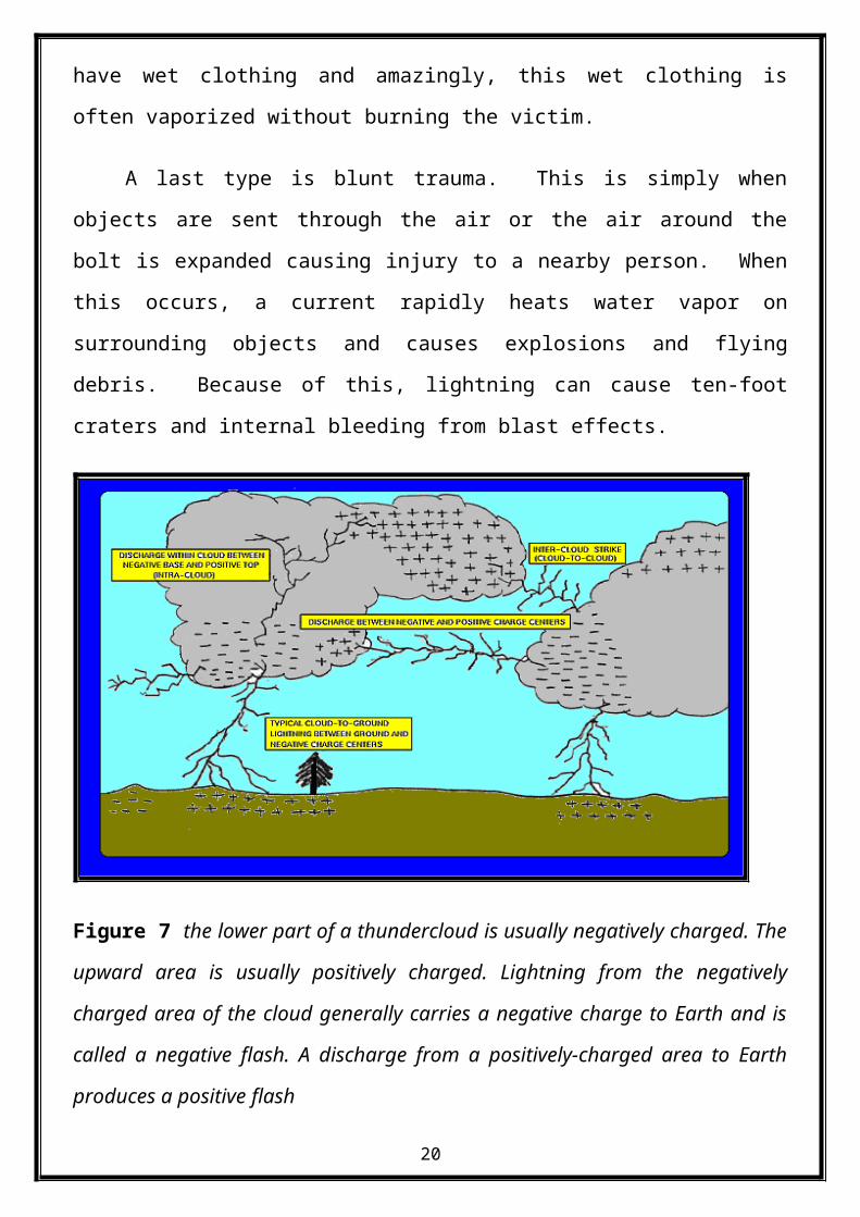
Figure 7 the lower part of a thundercloud is usually negatively charged. The upward
area is usually positively charged. Lightning from the negatively charged area of the
cloud generally carries a negative charge to Earth and is called a negative flash. A
discharge from a positively-charged area to Earth produces a positive flash
II. LIGHTNING DENSITY MAPS:13

Flash density :
Flash densities were calculated using the area for each individual grid, which changes
in size with latitude. No attempt was made to limit any region based on the number of
flashes detected within the grid (Reap and Orville 1990; Changnon 1993). A single
flash at any grid point counted the same as if there were multiple flashes. While it is
possible to have an errant flash location generate an erroneous count in the flash density
and flash hours, the effect on our study is assumed to be small. This assumption is
reasonable since the study includes all flashes occurring in the 8-yr period of record
(Table 1). Since the flash hours are calculated by 15- min intervals, the overall effect of
errant flash locations
The number of flashes occurring from 1989 to 1996 in the USA was counted for each
latitude and longitude grid resulting in the number of flashes per square kilometer or the
flash density (when divided by the area of the grid). Likewise, the number of hours that
each grid location experienced any lightning was determined in order to calculate the
mean flash hours. This is comparable to the number of hours that thunder is observed at
a location during the year and gives an estimate of the annual duration of
thunderstorms. Using the number of flashes and the number of hours when flashes
occurred, we can determine a mean flash rate for each of the grids. The number of
flashes each year across the United States is substantial (Table 1).
Table 1 the density in USA between (1989-1996) & (1995-1997)
The number of flashes over the continental United States (Table 1) shows two distinct
periods. The flash counts are 10 to 13 million flashes per year from 1989 to 1992 and 14

17 to 20 million flashes from 1993 to 1996. The increase in 1993 was due to the large
number of storms associated with the heavy precipitation and flooding in the Midwest.
From 1994 on, the increased flash counts can be attributed to the network upgrade
(Cummins et al. 1998). Positive flash counts show the same general trend only the
values for 1995–96 are 2– 4 times the values prior to the upgrade. This is a dramatic
difference compared to the total CG flash count indicating that the network upgrade had
a larger effect on the detection of positive flashes than the negative flashes.
The mean annual flash density for 1989–96 (Fig. 1) indicates a maximum over central
Florida (111 flashes km22 yr21) and relative maxima (seven flashes km22 yr21) over
southern Indiana, southern Oklahoma, and along southeastern Texas and the Gulf
Coast. Relative minima (three flashes km22 yr21) exist over the Appalachian
Mountains (the Virginias), southern Missouri, and along the Rio Grande. These features
were noted in previous studies of individual years (Orville 1991, 1994; Orville and
Silver 1997) and, as one would expect, there is good agreement between the individual
years and the 8-yr mean. There is a noticeable lack of lightning in the west coast states
(California, Oregon, and Washington) as well as Idaho and Maine. The annual studies
previously published (Orville 1991, 1994; Orville and Silver 1997) show similarly low
densities for these regions. No explanation for this is offered here.
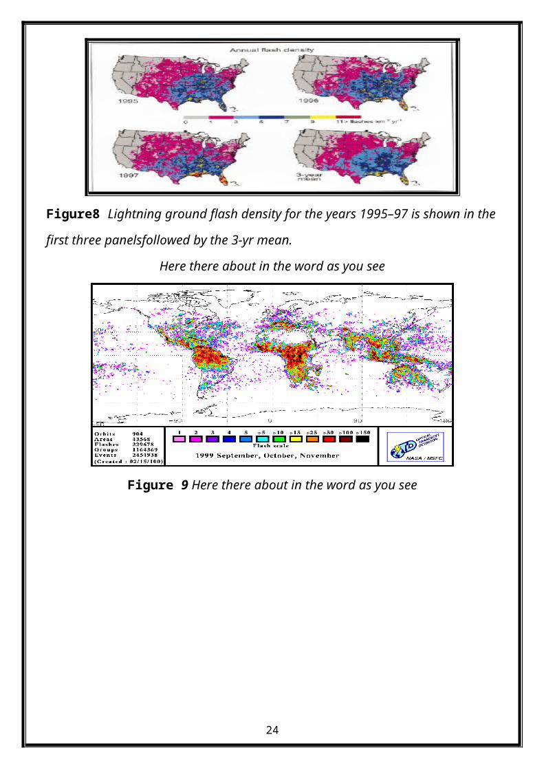
Figure8 Lightning ground flash density for the years 1995–97 is shown in the first
three panelsfollowed by the 3-yr mean.
Here there about in the word as you see
15

Figure 9 Here there about in the word as you see
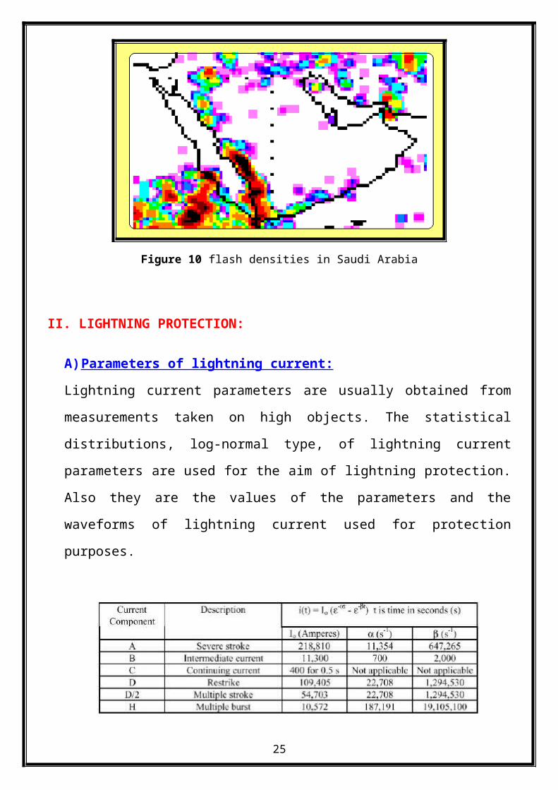
Figure 10 flash densities in Saudi Arabia
II. LIGHTNING PROTECTION:
A) Parameters of lightning current:
Lightning current parameters are usually obtained from measurements taken on high
objects. The statistical distributions, log-normal type, of lightning current parameters
are used for the aim of lightning protection. Also they are the values of the
parameters and the waveforms of lightning current used for protection purposes.
16
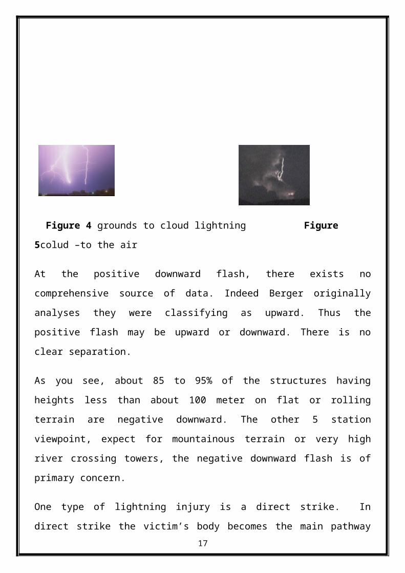
Table 2 Summary of Lightning Parameters from MIL-STD-464, Electromagnetic
Environmental Effects.
Figure 11 current of lightning with time
In figure 11 the y-axis is the peak current magnitude in kilo amperes (kA) and the x-
axis is the percentile ordinate. Examining this data, we find only 0.1% of all lightning
17

strikes exceeding 200 kA while 99.9% exceed 5 kA. The 50th percentile of peak current
magnitude is 28 kA.
The most important parameters for the purpose of designing protection systems are:
a Peak value of the first stroke: the lowest value of the statistical distribution of
current amplitude of downward flashes are important for the choice of the number
and position of the air termination system to prevent direct lightning flashes to the
structure to be protected (see section 10.7); the highest values of the statistical
distribution of current amplitude are important for sizing of protection measures
(electrodynamics effects etc.).
b Maximum rate of rise: the highest values of the statistical distribution are important
for dimensioning the protection measures in order to avoid inductive effects of
lightning current (induced overvoltages) and dangerous sparking.
c Flash duration and total charge in the flash: the highest values of the distribution
are important for sizing the air termination system aimed at limiting the thermal
effects at the impact point of the lightning flash.
d Specific energy in a flash: the highest values of the statistical distribution are
important for the selection of a conductor for the protective system, aimed at
preventing damage due to thermal effects and for setting up a suitable earthing
system in order to prevent hazard life.
For the protection of structures some additional information is necessary to assess more
general models of lightning phenomenon, such as charge distribution in the channel and
channel velocities.
Furthermore, in risk assessment it is crucial to know the average lightning flash density
(Ng) of the region where the structure and the incoming lines are placed. Ng values
(expressing the number of flashes per km2 per year)
can be assessed by different methods – thunderstorm day maps, lightning flash counters
– and, more recently, by lightning location systems.
18

(a) Lighting flashes to earth:
Two basic types of lightning flash exist, downward flashes initiated by a downward
leader from cloud to earth and upward flashes initiated by an upward leader from an
earthed structure to cloud. In flat territory and to lower structures mostly downward
flashes occur, whereas for exposed and /or higher structures upward flashes become
dominant. With the effective height the striking probability increases and the physical
conditions change.
Further differentiation of strokes comes from their polarity (positive or negative) and
from their position during the flash (first, subsequent, and superimposed). The possible
components are shown in figure 10.13 for downward flashes and in figure 10.14 for
upward flashes.
The additional component in upward flashes is the first long stroke without or
with up to some ten superimposed short strokes. But all short stroke parameters of
upward flashes are less than those of downward flashes. A higher long stroke charge of
upwards flashes is not yet confirmed. Therefore, for lightning protection, the lightning
parameters of upwards flashes are considered to be covered by the maximum values
taken from downward flashes. A more precise evaluation of lightning parameters and
their height dependency with regard to downward and upward flashes is still under
consideration in the scientific community.
(b)Lightning current parameters:
The lightning current parameters in this standard are bases on the results of CARE
given in Table 4. Their statistical distribution can be assumed to have a logarithmic
normal distribution. The corresponding means value µ and the dispersion log is given in
Table 12 and the distribution function shown in Figure 5. On this basis the probability
of occurrence of any value of each parameter can be determined
A polarity ratio of ten percent positive and 90 percent negative lightning is assumed.
The polarity ratio is a function of the territory. If no local information is available, the
ratio given herein should be used.
19
For lightning protection level I the fixed maximum values in Table 10.3 shall not be
exceeded with a probability of 99 percent. According to the polarity ration given above,
values taken from positive flashes must have probabilities below ten percent, those
from negative flashes below one percent.
Table 3 Tabulated values of lightning current parameters taken from CIGRE and fixed
values for lightning protection.
Paramet
er
Unit
s
Values Fixed
Values
For
level I
Stroke Type Line
in
95% 50% 5% Fig1
0.14
I kA 4(98%
)
20(80
%)
90 - * first negative short 1A+1
B
4.9 11.8 28.6 50 *Subsequent negative
short
2
4.6 35 250 200 First positive short
(single)
3
Qflash C 1.3 7.5 40 - Negative flash 4
20 80 350 300 Positive flash 5
Qshort C 1.1 4.5 20 - First negative short 6
0.22 0.95 4 - Subsequent negative
short
7
2 16 150 100 first positive short
(single)
8
W/R kJ/
Ω
6 55 550 First negative short 9
0.55 6 52 _ Subsequent negative
short
10
20

25 650 15.00
0
10.000 First positive short 11
di/dtmax kA/
µs
9.1 24.3 65 - * first negative short 12
Table 4 Continued
Paramet
er
Unit
s
Values Fixed
Values
For
level I
Stroke Type Line
in
95% 50% 5% Fig1
0.14
9.9 39.9 161.
5
- * subsequent
negative short
13
0.2 2.4 32 20 first positive short 14
di/
dt30/90%
kA/
µs
4.1 20.1 98.5 200 * subsequent
negative short
15
Qlong c 200 Long
Tlong s 0.5 Long
Front
duration
µs 1.8 5.5 18 First negative short
0.22 1.1 4.5 T1 =
0.25
subsequent
negative short
3.5 22 200 T1 =
10
First positive short
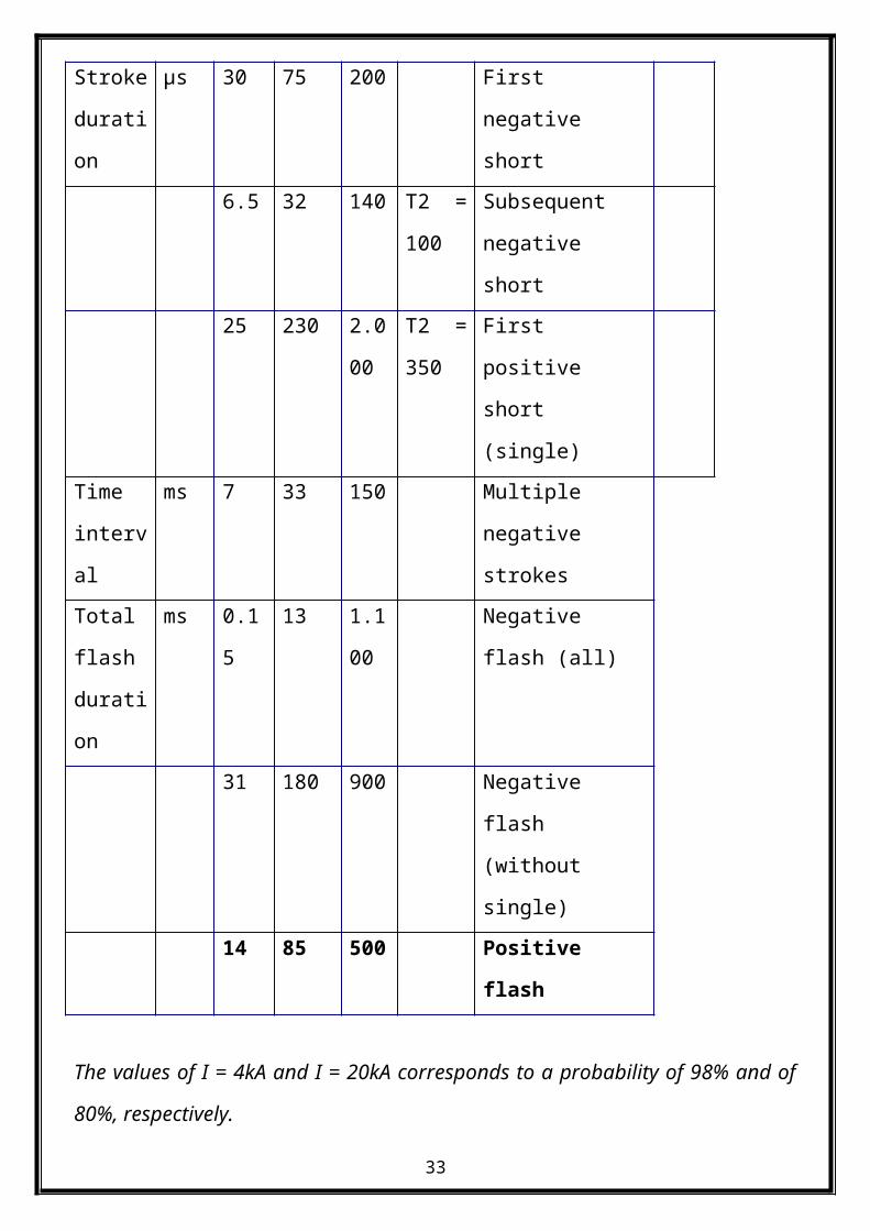
Stroke
duration
µs 30 75 200 First negative short
6.5 32 140 T2 = Subsequent
21

100 negative short
25 230 2.00
0
T2 =
350
First positive short
(single)
Time
interval
ms 7 33 150 Multiple negative
strokes
Total
flash
duration
ms 0.15 13 1.10
0
Negative flash (all)
31 180 900 Negative flash
(without single)
14 85 500 Positive flash
The values of I = 4kA and I = 20kA corresponds to a probability of 98% and of 80%,
respectively.
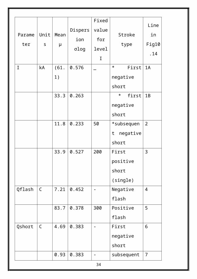
Parameter UnitsMean
µ
Dispersion
σlog
Fixed
value
for
level I
Stroke typeLine in
Fig10.14
I kA (61.1) 0.576 _ * First negative
short
1A
33.3 0.263 * first negative
short
1B
11.8 0.233 50 *subsequent
negative short
2
33.9 0.527 200 First positive
short (single)
3
Qflash C 7.21 0.452 - Negative flash 4
83.7 0.378 300 Positive flash 5
Qshort C 4.69 0.383 - First negative
short
6
22

0.938 0.383 - subsequent
negative short
7
17.3 0.570 100 First positive
short (single)
8
W/R kJ/ Ω 57.4 0.596 First negative
short
9
5.35 0.600 - subsequent
negative short
10
612 0.844 10.000 First positive
short
11
di/dtmax kA/µs 24.3 0.260 - * First negative
short
12
40.0 0.369 - * subsequent
negative short
13
2.53 0.670 20 First positive
short
14
di/dt30/90% kA/µs 20.1 0.420 200 * subsequent
negative short
15
Qlong C 200 Long
Tlong s 0.5 Long
Front
duration
µs 5.69 0.304 First negative
short
0.995 0.398 T1 =
0.25
subsequent
negative short
26.5 0.534 T1 = 10 First positive
short
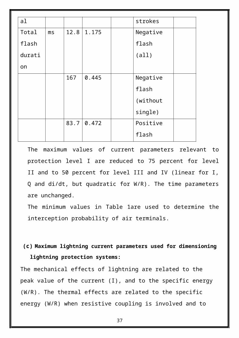
Stroke
duration
µs 77.5 0.250 First negative
short
30.2 0.405 T2 =
100
Subsequent
negative short
23
224 0.578 T2 =
350
First positive
short (single)
Time
interval
ms 32.4 0.405 Multiple
negative
strokes
Total
flash
duration
ms 12.8 1.175 Negative flash
(all)
167 0.445 Negative flash
(without single)
83.7 0.472 Positive flash
The maximum values of current parameters relevant to protection level I are reduced
to 75 percent for level II and to 50 percent for level III and IV (linear for I, Q and
di/dt, but quadratic for W/R). The time parameters are unchanged.
The minimum values in Table 1are used to determine the interception probability of
air terminals.
(c) Maximum lightning current parameters used for dimensioning lightning protection systems:
The mechanical effects of lightning are related to the peak value of the current (I), and
to the specific energy (W/R). The thermal effects are related to the specific energy
(W/R) when resistive coupling is involved and to the charge (Q) when arcs develop to
the installation. The dangerous sparking caused by inductive coupling is related to the
steepness (di/dt) of the lightning current front.
Each of the single parameters (I, Q, W/R, di/dt) tends to dominate each failure
mechanism. This is to be taken into account in establishing test procedures].
1. First short stroke and long stroke
The values I, Q, W/R related to mechanical and thermal effects are determined
from positive flashes (because their ten percent values are much higher than the
24
corresponding one percent values of the negative flashes). The following probabilities
below ten percent can be taken: I = 200 kA, Qflash = 300C, Qshort = 100C,
W/R = 10.000kJ/ Ω and di/dt = 20 kA/µs. For a first short stroke according to these
values give a first approximation for the front time:
T1 = I/(di/dt) = 10 µs
T2 is of minor interest. For an exponentially decaying stroke current the following
approximately applies (T1 << T2):
Qshort = (1/0.7) .I. T2
W/R = (1/2) . (1/0.7) . I2 . T2
These formulas together with the values given above lead to a first approximation for
the time to half value of T2 = 350 µs
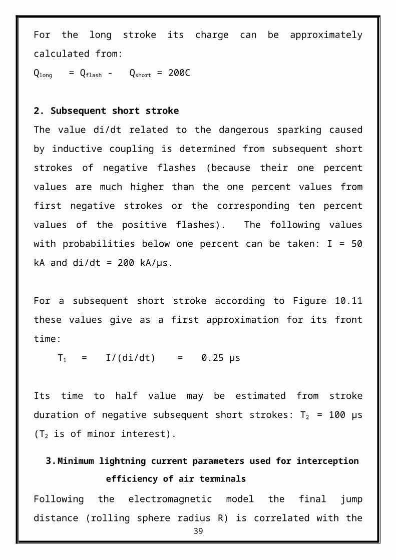
For the long stroke its charge can be approximately calculated from:
Qlong = Qflash - Qshort = 200C
2. Subsequent short stroke
The value di/dt related to the dangerous sparking caused by inductive coupling is
determined from subsequent short strokes of negative flashes (because their one percent
values are much higher than the one percent values from first negative strokes or the
corresponding ten percent values of the positive flashes). The following values with
probabilities below one percent can be taken: I = 50 kA and di/dt = 200 kA/µs.
For a subsequent short stroke according to Figure 10.11 these values give as a first
approximation for its front time:
T1 = I/(di/dt) = 0.25 µs
Its time to half value may be estimated from stroke duration of negative subsequent
short strokes: T2 = 100 µs (T2 is of minor interest).
25

3.Minimum lightning current parameters used for interception efficiency of
air terminals
Following the electromagnetic model the final jump distance (rolling sphere radius R)
is correlated with the peak value of the first short stroke. According to the IEEE
working group report [39] the relation is given as:
R = 10.I0.65
Where R is the rolling sphere radius (m) and I is the peak current (kA).
For a given rolling sphere radius R it can be assumed that all flashes with peak values
higher than the corresponding minimum peak value I will be intercepted by the air
terminations. Therefore, the probability for the peak values of first strokes from Figure
is assumed as interception probability. Taking into account the polarity ratio of ten
percent positive and 90 percent negative flashes the total interception probability can be
calculated.
B. Classification of structures of lightning :
For the purposes of lightning protection structures may be usefully classified according
to consequential effects of lightning flash which can cause damage to the structure their
contents or their surroundings:
Common structures
Structures with risk of explosion, containing solid explosive materials or hazardous
zones type 0 as determined in IEC 60079-10; for the purposes of lightning
protection, structures with hazardous zones type 1 or type 2 are not considered to be
at risk of explosion due to very low probability of contemporary presence of
lightning and explosive gas atmospheres
Structures with electronic systems, in which a large amount of electronic equipment
is installed, such as systems including telecommunication equipment, control
system, measuring systems
Structures dangerous to the environment, which may cause biological, chemical and
radioactive emission as a consequence of lightning, such as chemical, petrochemical,
nuclear plants etc.
26

Structures may be also classified according to the risk of fire:
(i) Structures with high risk of fire:
Structures made by combustible materials
Structures with a roof made of highly combustible materials
Structures with a specific fire load larger than 45 kg/m2
(ii) Structures with an ordinary risk of fire:
Structures with a specific fire load between 20 and 45 kg/m2
(iii) Structures with low risk of fire:
Structures with specific fire load of less than 20 kg/m2
Structures containing combustible materials only occasionally
The specific fire load may be calculated as the ratio of the total amount of combustible
material and the overall surface of the structure.
C. Damage due to lightning
Lightning striking a structure can result in damage to the structure itself and to its
occupants and contents, including failure of equipment and especially of electrical and
electronic systems. The damages and failures may also extend to the surrounding of the
structure and may even involve the local environment. The scale of this extension
depends on the characteristics of the structure and on the characteristics of lightning
In addition to being beautiful and scientifically fascinating, lightning can be destructive
to buildings and to numerous systems critical to daily life, and it can be lethal to people.
We are all aware of stories of lightning striking people (Lee Trevino twice) or causing
forest fires. Less often but occasionally spectacularly in the news are incidents of
extremely costly and tragic fires or explosions caused by lightning at industrial or
military sites. This brief overview primarily considers lightning damage to structures,
not people.
A typical lightning stroke is a dramatically powerful natural event capable of damaging
even intentionally protected structures. The lightning stroke reaches temperatures of
several tens of thousand degrees Kelvin, clearly sufficient to initiate combustion in 27

many common materials. Indeed, when lightning current dissipates into the earth it
often melts sand, creating glassy channels called fulgurites that can be tens of feet long.
The cloud-to-ground voltage of thunderheads can be many tens of million volts, and the
current in a lightning stroke can exceed 200 thousand amperes (>1000 times the typical
household wiring capacity). When lightning strikes a building, it can cause internal
electric fields in excess of 100 thousand volts per meter and can cause internal arcing
across rooms. The energy released by a lightning strike can be of the order of 1010
Joules, more than the energy in 1000 gallons of gasoline or more than the energy of
some bombs. Fortunately, only a small portion of this energy couples to the building to
produce damage.
Among the damaging effects of lightning are the following:
Fire – Lightning is a major cause of forest and range fires. It presents a daily fire
threat to buildings and other commercial structures. The existing lightning
protection industry primarily addresses the fire threat, and significant
expenditures have historically been made to mitigate this threat.
Fracture and spelling – In many common materials lightning current causes a
rapid localized expansion that causes the material to fracture or split apart. This
effect can be observed in trees that have been split by lightning or in masonry
buildings that have bricks "blown" off.
Voltage surges – Lightning strikes to power lines cause a transient over-voltage
pulse to be transmitted for miles. You have probably installed power strips with
over-voltage clamps in them to protect your PC, TV and Stereo. This works well
for distant strikes.
High electric fields and arcing – When lightning directly strikes a building it can
cause electric fields inside the building that can damage or disrupt electronics and
can cause internal arcing. In industrial sites, disruption of controlling electronics
can have extremely costly consequences including long down time and destroyed
equipment. Arcing can also damage or disrupt electronics.
28

Explosions – For industrial sites housing volatile compounds and military sites
housing explosives, lightning induced arcs can directly initiate explosions, or
lightning caused fires can subsequently cause explosions.
Fires and spalling cause damage to the structures or buildings that lightning strikes.
Voltage surges on power lines cause damage or disruption to electronic systems. You
will soon understand that both conventional and modern lightning protection mitigate
damage from these causes. High electric fields and arcing cause damage or disruption
to electronic systems, and you will soon understand that only modern lightning
protection mitigates this damage. (That is, only modern protection mitigates all types of
lightning damage.) Of course, explosions can damage both the structures and their
contents, including electronic systems.
To understand better how lightning causes these effects, consider the typical lightning
current waveforms in Figure 1.3. As described in the previous menu item (Lightning
Physics), here lightning current is seen in the two example waveforms to consist of an
initial stroke typically followed by several subsequent strokes – on the average about
four subsequent strokes but occasionally perhaps 10 - 20. Each stroke is seen to consist
of a very rapid rise (often <0.5 microsecond) to a high peak current followed by a much
slower decay (~500 microseconds) to near zero current. For about 25% to 50% of
lightning strikes, on a subsequent stroke the initial rapid rise and slower decay are
followed by a much lower and slower continuing current (~100 - 500 amps for several
hundred milliseconds).
29
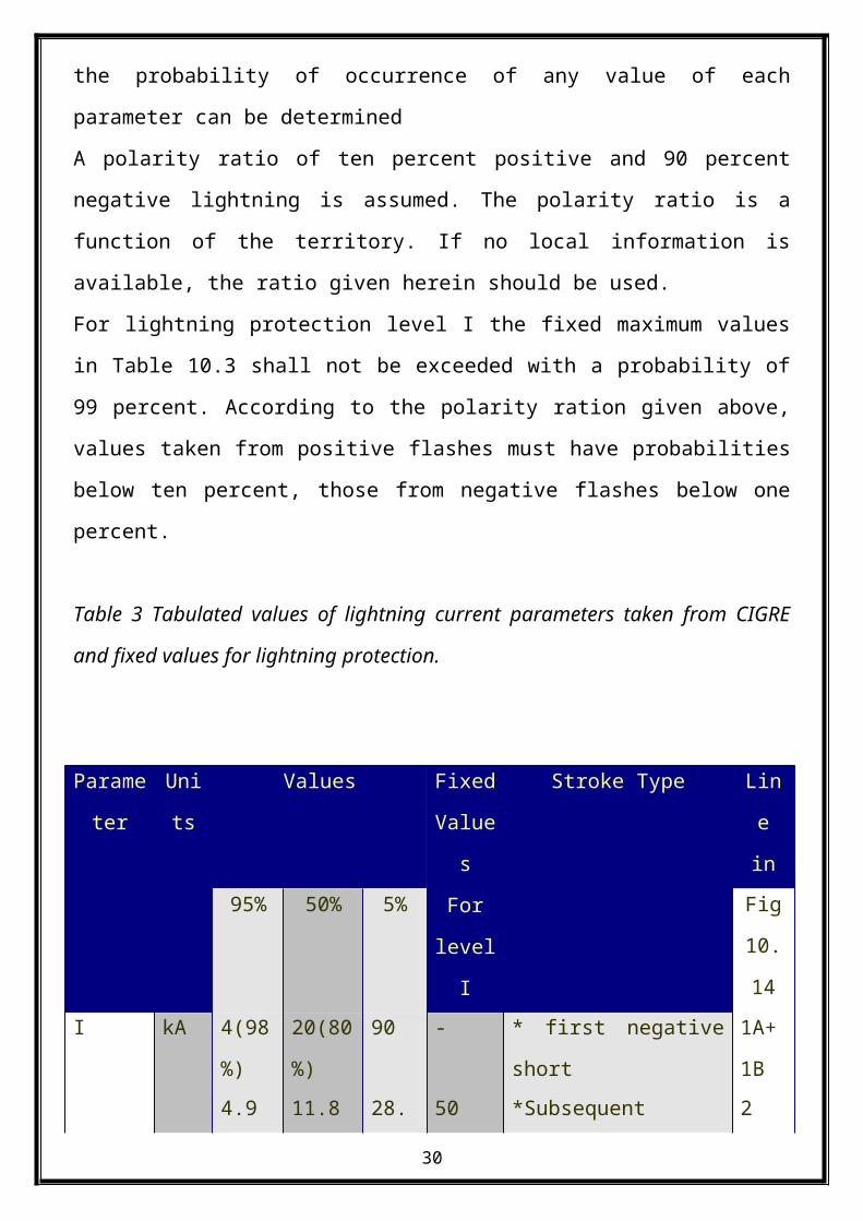
Figure 12Lightning Current Waveform
The characteristics of the rapid current rise at the beginning of each stroke are
important in causing arcs and in modern lightning protection:
Peak currents of 200 kilo amperes and the peak rate-of-rise of current of 400 kilo
amperes per microsecond are accurate estimates for extreme (99 percentile)
lightning characteristics.
For nominal (50 percentile) lightning flash attachment, peak currents of 30 kilo
amperes and the peak rate-of-rise of current of 150 kilo amperes per microsecond
are accurate estimates.
The total charge transferred (the integrated current) and the "action integral" are
important in causing heating and thus in causing fires and spelling. (The action integral
is the time integral of I2(t)R, where R = 1 ohm.) Both of these measures are dominated
by the low frequency components of lightning. Typically, spalling results from the
rapid conversion of moisture to steam. The steam creates pressure, which fractures the
material, causing rapid and violent spalling.
As stated, the rapid current rise and peak current (the high frequency components of
lightning) result in high electric fields and subsequent arcing in a building struck by
lightning. To understand this effect, consider that many buildings, particularly modern 30

buildings, can be modeled as a series resistor, R, and inductor, L . Given this simple
model, the voltage, V, between the floor and ceiling that results from the current, I, is
the following:
As a very good approximation of the upper bound of the maximum voltage, the peak
current and peak rate of current rise stated above can be used:
An upper bound for Vmax occurs when the current parameters from extreme lightning
are used. The maximum voltages and consequent electric fields often exceed the
breakdown strength of air; thus, arcs are generated. The current parameters for the
slower current decay and for continuing current generate much lower maximum
voltages and thus generate much lower electric fields, which typically do not produce
arcs, but can sustain the arcs once started.
In summary, the dominant cause of fires and spalling is the low frequency energy in the
current decay and continuing current. The dominant cause of over-voltage, high electric
fields and arcing is the initial peak current and its rise time; this region is very short in
duration with high frequency energy content. Remember these causes for lightning
damage; they will be revisited when we consider conventional lightning protection and
modern lightning protection in subsequent menu items.
In the US on average, lightning strikes to ground occur about 4 times per square
kilometer per year. Florida, the lightning capital of the US, has about 15 to 30 strikes to
ground per square kilometer annually, and Nevada only a few strikes per square
kilometer annually. Some regions of the world have more frequent strikes than Florida,
particularly tropical regions. From lightning density statistics one can calculate the
expected strikes per year to facilities based on their footprints. Many industrial systems
have surprisingly large footprints for lightning attachment. For example, pipelines can
31

transmit lightning energy for miles, and lightning can attach to pipelines from about 30
feet away. In Florida there are estimated to be up to one lightning attachment per
pipeline mile per year.
The total loss caused to US property by lightning damage probably exceeds $5 billion
per year. Many instances of lightning damage go unreported so an accurate total
estimate of cost is difficult. Some interesting categories of damage cost are the
following:
Half the forest fires are lightning caused, costing about $100 million annually.
About 5% (~$1 billion) of annual insurance claims are lightning related.
About 30% (~$1 billion) of annual power outages are caused by lightning.
Over 100 thousand PCs (~$100 million) annually are destroyed or damaged by
lightning.
a. Effects of lightning
The main characteristics of structures of relevance to lightning effects include:
Construction (wood, brick, concrete, reinforced concrete, steel frame)
Function (dwelling house, office, farm, theatre, hotel, school, hospital, museum,
church, prison, department store, bank, factory, industry plant, sports area)
Occupants and contents (persons and animals, noninflammable materials,
inflammable materials, nonexplosive mixtures, explosive mixtures, equipment
immune to electromagnetic fields or sensitive to electromagnetic fields)
Entering installations (electricity mains, telecommunication and data lines, other
services)
Measures to limit consequential effects of damages (e.g. protection to reduce
mechanical damages, the consequences of fire, protection to limit the concentration of
explosive mixtures, protection to limit the overvoltages, protection to limit step and
touch voltages)
32
Scale of the extension of danger (structure with small local danger, structure with
greater but confined danger, structure with danger to the surroundings, structure with
danger to the environment).
b. Causes and types of damage
The lightning current is the source of damage. The following causes of damage are to
be taken into account according to the position of the striken point in relation to the
structure [4]:
Flashes direct near the structure
Flashes direct to the incoming lines (mains, telecommunication and data lines) or other
services
Flashes to ground near the structure
Flashes to ground near the incoming lines and services.
Direct flashes to the structure can cause:
Immediate mechanical damage, fire and/or explosion initiated by sparks caused
by overvoltages resulting from resistive and inductive coupling
Fire and/or explosion inititated by sparks caused by overvoltages resulting from
resistive and inductive coupling
Injuries to people by step and touch voltages resulting from resistive and
inductive coupling
Failure of electrical and electronic system due to passage of part of the lightning
currents and to overvoltages resulting from resistive and inductive coupling
Failure of apparatus internal to the structure due to direct coupling of lightning
electromagnetic impulsive field (LEMP).
33
Direct flashes to the incoming lines can cause:
Fire and/or explosion triggered by sparks due to overvoltages appearing on
external power lines entering the structure
Injuries to people due to over currents and to overvoltages appearing on external
lines entering the structure
Failure of electrical and electronic systems due to overvoltages appearing on
external lines entering the structure.
Flashes to the ground surface near the structure can cause:
Failures or malfunction of electrical and electronic systems due to overvoltages
resulting from inductive coupling with lightning current.
Figure 13Types of loss resulting from different types of damage
Failure of apparatus internal to the structure due to their direct coupling with LEMP.
Flashes to the ground surface near incoming lines can cause:
Failure or malfunction of electrical and electronic systems due to overvoltages induced
in external lines entering the structure.
As result, the lightning can cause three basic types of damage:
34
Risk 1 Risk 2 Risk 3 Ris

(i) shock to living beings due to touch and step voltages
(ii) fire, explosion, mechanical destruction, chemical release (physical damages)
due to mechanical and thermal effects by lightning current including sparking
(iii) failure of electrical and electronic systems due to overvoltages.
c. Types of loss
Each type of damage, alone or in combination with others, may produce different
consequential loss in a structure. The type of loss that may appear depends on the
characteristics of the structure.
According to the following types of loss are to be considered:
Loss of human life
Loss of service to the public
Loss of cultural heritage
Loss of economic value (structure, content and loss of activity)
More than one loss may appear in a structure. Loss of economic value always appears.
The first three losses belong to social value; the fourth loss belongs to private property.
How lightning disturbances can affect electronics?
A typical lightning 'strike' can last for over one second and consist of many 'strokes'
(discharges), sometimes over ten, each with an 'arc-channel' current of between 2kA
and 200kA (1% of strokes exceed 200kA).
Earth lift. Soil has significant resistance, so lightning strokes can cause large
potential differences between areas nominally at the same 'earth' potential. [8]
shows that the 'traditional' practices (which are not recommended in this series)
of star earthing and bonding cable screens at only one end makes this sort of
damage more likely.
Magnetic induction. Very high surge voltages can be induced into any conductors
by magnetic coupling from lightning strikes up to 100 meters away.
35

Current injection. Direct strikes to external equipment or cables often results in
damage to the internal equipment they are connected to, and can damage
unrelated equipment due to side-flashes in shared cable routes or terminal
cabinets.
Electric induction. Electric fields of up to 500kV/m can occur before a lightning
strike, over an area of up to 100m from the eventual strike point. These can
induce damaging currents into conductors and devices.
Lightning Electromagnetic Pulse (LEMP). This 'far-field' effect can be caused by
cloud-to-cloud lightning as well as by distant cloud-to-ground strokes.
Thermal and mechanical effects (e.g. shock waves in the air) due to the intense
energies associated with lightning. Mostly affects a structure's fabric and its
lightning conductors.
Multiplicity and duration of strokes in a single strike. This is important for error-
correction and system software recovery.
This article focuses on the type of lightning protection systems (LPSs) described by [3]
and [4], which intercept the strikes and route them to earth. In so doing they create
locally intense electromagnetic disturbances which can damage electronic equipment
and/or corrupt data unless the techniques described here are used, although of course
these local disturbances are much less damaging than having no LPS at all.
A number of people are proposing a different lightning protection technique, sometimes
called 'early streamer technology', which is claimed to use discharges from metallic
points to neutralise the electric fields and prevent lightning strikes from happening in
the first place. If this works as claimed it would clearly be of great benefit for protecting
electronics. An example of an article commending this new technique is in [9]. If you
plan to use any novel techniques such as 'early streamer' on your next project it would
be a good idea to check that it won't suffer from excessive buildings insurance policy
rates.
36
Overview of a basic lightning protection system (LPS)
First we'll take a brief look at basic LPSs to protect people and the structure in typical
commercial or industrial buildings, based on [4] (the UK's code of practice for lightning
protection), and then we'll see how to enhance them to protect electronics. LPS design
should always be done by an experienced, competent professional who involves all
interested parties before, during, and after all stages of design, including: architects;
utilities (gas, water, power, telephone, etc.); the owner's Fire and Safety Officers; TV
radio security and telecommunications system installers; and the builders.
A typical LPS intended just for personnel safety, and protection of the structure,
typically requires:
A risk assessment based on actual lightning exposure
Design of the air termination network and down-conductors
Design of the earth termination network and earth electrodes
Bonding of the metalwork within a structure, and of the metallic services entering
a structure, to the LPS.
Special structures may require special LPS measures.
Risk assessment is based on lightning strike density maps called isokeraunic (or
isoceraunic) maps, plus:
The structure's 'effective collection area' for lightning strikes.
Its use.
Its type of construction.
Its contents.
The consequential effects of any damage.
The degree of its isolation from other structures.
The type of terrain.
All of these are easily found using [4], and determine whether an LPS is considered
essential or not. Lightning standards also provide guidance on the anticipated
37

characteristics of lightning strikes (e.g. the maximum stroke current: much higher in the
tropics than in the UK).
(a) The basic construction of an LPS
A basic LPS consists of an air termination network, a down-conductor network, and an
earth-termination network, as shown in Figure 5A. The air termination network
intercepts the actual lightning strike and diverts it via the down-conductors to the earth
termination network, thereby protecting the structure. Single conductor LPSs are not
recommended any more - they tend to flash-over to the rest of the structure, and their
strong voltage gradients at ground level can cause safety hazards.
Figure 14
An LPS must withstand extremes of weather, electrical, electromagnetic, and
mechanical stresses, and last many years, and only certain metals and combinations of
metals are suitable. Metal parts of the structure ('natural' components, including re-bars)
can often be used as parts of the LPS, or even as the whole LPS, providing they meet
specified requirements. Copper theft from external LPSs is a serious concern, so the use
of 'natural' components is often preferred.
The air termination network can be a mesh of conductors on roofs and the outsides of
walls. Different types of air terminations create differently-shaped 'zones of protection'
to protect exposed equipment such as antennae, radar and satellite dishes, security
38
cameras, air-conditioning plant, water tanks, etc. from direct strikes. A closer mesh is
needed for more vulnerable structures, such as fuel or explosives stores (we shall see
later that the same helps to protect electronics). An all-metal all-welded structure
provides the perfect air-termination network, and of course is ideal for electronic
protection too.
There should be several down-conductors equi-spaced around the structure, to share the
lightning current from the air termination network. They should be straight and vertical
to provide the most direct route to the earth electrodes, with special rules for when they
can't be.
The earth termination network is the system of earth electrodes which dissipates the
lightning currents into the mass of the soil and/or rock beneath the structure to be
protected. All soils and rocks have finite conductivity, and [4] describes what should be
done in the design, construction and maintenance of earth electrodes to achieve an
overall earth resistance of 10 Ohms. Higher (or lower) resistances may be allowed (or
needed) in special cases.
An LPS with an overall earth resistance of 10 Ohms and a (not excessive) lightning
current of 100kA can cause an 'earth lift' for the structure of 1MV. Clearly it is
important to have a good CBN within a structure, and to design the earth electrodes to
control the voltage gradient around it to keep the 'step voltage' during a lightning strike
within acceptable levels. It is no good putting up signs warning people in or near a
building to take very small steps during thunderstorms!
Typical earth electrodes include rod electrodes at the foot of each down-conductor a
metre or so from the structure's boundary, driven vertically into the soil. Reinforcement
in concrete foundations (especially pilings) can achieve a very low earth resistance, and
is called a foundation earth electrode. Lengths of conductor run under the soil are strip
electrodes, but when used to reduce voltage gradients they may be called potential
grading electrodes. A foundation strip electrode is a strip electrode laid in the trench cut
for the foundations of a structure, before they are laid or poured. A ring earth electrode
follows the perimeter of a structure at a given distance, bonding all the other electrodes 39

and forming an unbroken ring (like the internal bonding ring conductors (BRCs)
described in Part 2 of this series [11]).
Preventing side-flashes
During a lightning strike the high rate of change of current in down-conductors (up to
100 kA/m.ms for a conductor carrying 50% of the strike current) can give rise to very
high voltages from top to bottom, due to the inevitable inductance of the conductors,
possibly as much as 100kV/metre of height. These can 'side-flash' to other metalwork,
even right through the fabric of the structure (bricks, concrete, windows, etc.) often
causing cosmetic or structural damage and frightening those personnel that aren't
injured. Prevention of side-flashing uses three techniques, given here in order of
preference:
Increasing the number of down-conductors and reducing the mesh size of the
LPS, to reduce inductance and reduce the potential differences.
Bonding the LPS to any metalwork or conductors it might side-flash to (both
external and internal).
Isolation by achieving large clearance distances between the LPS and the things
it might side-flash to (may need >2 metres in air).
Bonding the LPS to internal metalwork usually means bonding to the CBN (as shown
in Figure 1 of Part 1 of this series). Although this allows lightning currents to flow
internally, it is not a problem for a structure that has a well-meshed CBN because the
lightning currents tend to concentrate in conductors at the outer edges of a structure.
The unwanted currents that do flow are a small price to pay for freedom from side-
flashes.
(b) Bonding external cables and metallic services to the LPS
All metal entering or leaving a structure - whether cable sheathing, screening or
armouring, or piping for electric power, gas, water, rain, steam, compressed air, dry
risers, or any other service - should ideally be bonded directly to the main earthing
terminal (MET), as near to the point at which the service enters or leaves the structure
40

as possible. So planning and design should aim to bring all services and external cables
in at a single area, preferably within 2 metres of the MET.
Power and signal conductors, and any other metal items that can't be bonded to earth,
should have surge protection devices (SPDs) connected to the MET. Figure 5B shows
general bonding principlesm.
Figure 15
All metallic cables and services should ideally have travelled underground for their
entire length. Overhead cables and services are very exposed and there are special rules
for dealing with these. Even telephone wires should also enter underground where
possible, but most lightning standards dodge the issue by stating that their safety is the
responsibility of the appropriate Telephone Utility.
(c) How much lightning current flows in external cables?
Some lightning current will flow in the external cables and metallic services bonded to
the LPS, and their levels may be assumed to depend on their resistances - compared
with the earth electrode system's resistance. [4] provides (statistical) figures for the
lightning currents to be expected, so once the various resistances are known (calculation
or measurement) a simple calculation based upon parallel resistors will indicate how the
lightning current will divide up.
41

Where an individual evaluation isn't done, [13] suggests that 50% of the total lightning
current in the LPS may be assumed to enter its earth termination network - the rest
being distributed equally among the metallic cables and services entering or leaving the
structure. Screened or armoured cables may be assumed to carry all of their portion of
the current in their screen or armour. Unscreened and unarmoured conductors may be
assumed to distribute their portion of the lightning current equally among their
conductors. Telephone cables that enter the structure above ground level may be
assumed to carry currents of up to 5% of the main lightning arc channel current. An
appendix in [3] shows how to calculate the surge current handling capacity of a cable,
screen, or amour.
D. Main features of lightning protection system (LPS)
a. External lightning protection system
The external LPS is intended to intercept direct lightning strokes, including flashes
to the side of structure, to conduct lightning current from the point of strike to
ground and to disperse it to earth without causing thermal, mechanical and electrical
damages to the structure to be protected, including sparking and touch and step
voltages dangerous for persons inside the structure. Protection measures additional
to external LPS may be required in order to avoid the hazard due to touch and step
voltages for persons outside the structure in the vicinity of the down conductor
system.
In most cases, the external LPS may be attached to the structure to be protected. An
isolated external LPS should be also considered when the thermal and explosive
effects at the point of strike or on the conductors carrying the lightning current may
cause damage to the structure or to the content. Typical cases are:
42

Structures with combustible covering
Structures with combustible walls
Areas with danger of explosion and fire
Dangerous sparking between an LPS and structures shall be avoided:
In an isolated external LPS by insulation or separation
In a nonisolated external LPS by bonding or by insulation or separation.
Natural components made of conductive materials that will always remain in the
structure and will not be modified (e.g. interconnected reinforced steel, metal frame-
work of the structure etc.) should preferably be used as part of the LPS. Other natural
components should be used as additional to the LPS.
VI. LIGHTNING WITH OVERHEAD ELECTRICAL NETWORKS:
STUDY OF LIGHTNING INDUCED VOLTAGES ON OVERHEAD
CONDUCTORS
Overview:
Electrical power delivery consists of two parts. They are transmission and
distribution. The conductors are drawn through the country area exposing them to the
normal environment. For the protection of these two line systems from the surge
voltages are of utmost importance for the proper operation of power system. It is
needed to decide maximum transient surge voltage to set the protections (Basic
insulation level) for lines and substation equipments.
Lightning over voltages are important when the distribution system is considered rather
than transmission systems which have higher basic insulation levels. For lightning over
voltages on distribution lines, the induced voltage due to direct stroke and induced
voltage due to lightning to a near place or object are considered. In this context we are
considering only voltage magnitudes but not flash densities and their occurring
43

probabilities. The theory for deciding the voltage due to direct stroke is straight forward
and to decide the induced voltage is somewhat complex. In this context we are using
the equations from IEE & IEEE transactions and some other references. Using these
equations we have implemented computer program to calculate the induced voltage on
a distribution line of a multi-conductor system and to draw the graphs between induced
Voltages vs. Time. In this program we have taken into consideration the effect of a
single earth wire with grounding only at one point for simplicity. Also some effort to
explain the reasons for the incident that says “Lightning surges are affected severely to
the end users of the line rather than other users.” has been taken in this context and we
are suggesting a method for minimizing that effect.
3. Induced voltage on a conductor due to .lightning to a nearby place
The Chowdhuri model will be used in our analysis.
Figure 16
3.1 Geometrical model of the position of strike and Conductors.
Lightning induced voltages on overhead conductors.
2. Over voltage due to direct stroke
3. Figure 17
44

Io-Lightning current magnitude
Z- Surge impedance of the line
E- Induced voltage on the line
This induced voltage will travel along the line instantly to both ways from the point of
strike. Voltage magnitude is given by following equation. [1]
E = (Io/2) * Z
3.2 Basic assumptions
a) The lightning stroke is a vertical channel with the single return stroke originating
from the ground plane at time t=0.
b) Velocity of return stroke is constant.
c) Charge distribution along the leader stroke is uniform.
d) Line conductor is loss free and earth is perfectly conducting.
e) A rectangular system of co-ordinates in space is chosen and its notation is shown in
above figures.
3.3 Equation with the correction
For current waveform as below
V(x, t) = u(x, t) for to < t < tf
=u(x, t)-u(x, t-tf) for t>tf
=0 for t<to
Where to=Zo/ (B*c)
Zo-Retarded height of the stroke
V-velocity of return stroke where V=B*c
C-velocity of light
U(x, t) =30*Io*h/ (tf*B*c)*[ln (q1-q2)]+60*Io*h/ (tf*c)*[q3-q4] +30*Io*h/ (tf*B*c)
*[q5+q6+q7+q8+q9+q10+q11+q12+q13]
q1= [(1-B2)*(B2*x2+Yo2) +B2*c2*t2*(1+B2)]/ (1-B2)2*Yo2
q2= [-{2*B2*c*t*(B2*c2*t2 (1-B2)*(x2+Yo2)}/ (1-B2)2*Yo2]
q3=sinh-1[B*c*t/ (1-B2)1/2]
q4= -sinh-1[B*c*to/ (1-B2)1/2]
45

q5= -ln [(c2*t2-x2)/Yo2]
q6=1/2*cosh-1{(u1+p)/ (p2-q12)1/2}
q7= -1/2*cosh-1{(uo+p)/ (p2-q12)1/2}
q8=1/2*cosh-1{(z1+p/q12)/ (p2/q14-1/q12)1/2}
q9= -1/2*cosh-1{(zo+p/q12)/ (P2/q14-1/q12)1/2}
q10=1/2*cosh-1{(w+p)/ (p2-q12)1/2}
q11= -1/2*cosh-1{(WO+p)/ (p2-q12)1/2}
q12=1/2*cosh-1{(v1+p/q12)/ (P2/q14- 1/q12)1/2}
q13= -1/2*cosh-1{(VO+p/q12)/ (P2/q14- 1/q12)1/2}
w=(c*t+x)-2 w0=(c*to+x)-2
v1=(c*t+x)2 vo=(c*to+x)2
u1=(c*t-x)-2 uo=(c*to-x)-2
z1=(c*t-x) 2 zo=(c*to-x) 2
p= (Yo2+2*Zo2)/Yo4
q1=1/Yo2 1/Yo2
Figure 17
4. Analysis of effectiveness of earth wires for
.....induced lightning surges. [3]
Figure 1846

Iu (Xk, t)-Current flowing through the earth. connection at the point Xk
Uv, (Xp, t)-Suppressed voltage at point Xp Uv (Xp, t)-Induced voltage without earth
connection Zvu-Mutual surge impedance between conductor u and. v. Zuu-Self surge
impedence of conductor u. Uv ’(Xp,t) = Uv(Xp,t) - {1/2.Ævu* Iu[Xk,t-
mod(Xk-Xp)/Vc]}
Where m-number of earthling wires n-number of earth connections for a line Iu (Xk, t)
= [Uu ’ (Xk,t)]/(R+Zuu/2)
• In most cases one earth wire and one earth connection is used
Ui (Xp,t) = Uv (Xp,t)-Zvu/(2R+Zuu)*Uu(Xp,t)
• Magnitude of induced voltages is proportional to the height of the conductor.
5. Lightning effect to the end user
Explanation for the problem that the end .user of the line is subjected to the highest
....effect of the lightning induced voltage.
Suppose the below simple distribution system P,Q and R-user points
E-Surge voltage magnitude
Z-Surge impedance of the distribution line
Z1, Z2, Z3- Surge impedances of user lines
S- End point of the line
A1, A2, A3- First transmission coefficients at .P,Q and R
B1, B2, B3- First reflection coefficients at P,Q .and R
Figure 19
Consider point P.[1] ,
Z’=Z*Z1/(Z+Z1)
B1=(Z’-Z)/(Z’+Z) A1=2Z’/(Z’+Z)
• Surge impedance of distribution line is
47

Z=60ln(d/r)
• Surge impedance of user line is
Z1=60/ €r ln(d/r)
Where d-conductor spacing r-conductor radius
€r-relative permittivity of the insulating material of user lines.
As €r is a higher value, Z1 is small. Due to that A1 is very low.
Therefore surges felt by the user ( A1*E ) is small at points like P & Q.
At ‘S’ the total surge voltage is 2E due to reflection at open end.
There fore the surge voltage felt by the user at ‘R’ is A3*2E. So maximum surge
voltage is felt by end user.
6) Methods for overcoming this problem.
6.1 By using an earthling transformer at end (S).
Surge impedance of the earthling transformer should be low so that reflection
coefficient at end to be less than 1. Then total voltage due to. reflection will be less than
2E.
6.2 By using a surge arrester at the end.
Use a surge arrester with discharging voltage slightly higher than the maximum
operating voltage at the end. Then it limits the voltage .build up at the and to a safe
value.
B) Lighting-induced voltages on overhead power lines
i) Return stroke current model, computation of the incident electromagnetic
field, and coupling model
A computer program (LIOV, lighting-induced overvoltage) was developed by the
authors of this Chapter, which allows for the evaluation of lighting-induced voltages on
a multi-conductor overhead line above a lossy ground (see [58,20] for the theoretical
48

background). LIOV has been developed in the framework of an international
collaboration involving the Universities of Bologna (Department of Electric
Engineering), the swiss Federal Institute of Technology (Power Systems Laboratory)
and the University of Rome La Sapienza (Department of Electrical Engineering). The
code is based on the field-to-transmission line coupling formuation of Agarwal et al.,
suitably adapted for the calculation of induced overvoltages when lighting strikes near
horizontal overhead transmission line. In the LIOV code, the electromagnetic field
radiated by lighting channel is calculated using the field equations in the form given by
Uman el al. [59] with the extension to the case lossy ground introduced by Cooray and
Rubinstein [60,61] and assuming the modified transmission line (MTLE) return stroke
current model for the description of the spatial – temporal distribution of the lighting
current along the return stroke channel (Nucci et al. [16]; Rachidi and Nucci [62]). The
amplitude decay constant of the MTL model, λ, is fixed at 2 km, as implied in [63] by
means of simultaneously measured electromagnetic fields at two different distances.
The forcing functions in the Agarwal et al. coupling model are expressed, as seen in
section 8.2.3, in terms of the vertical and horizontal electric field components. The
vertical electric field radiated by the lighting channel is calculated assuming the ground
as a perfectly conducting plane, since such a field component is not affected
significantly by the soil resistivity in the frequency and distance range of interest, using
the equation of Chapter 5. For the calculation of the horizontal electric field
components, we adopt the approximate formula proposed by Cooray and Rubinstein
[60,61].10
The LIOV code allows for the calculation of lighting-induced voltages along an overhead
line as a function of lighting current waveshape (amplitude, front steepness, and
duration), return stroke velocity, line geometry (height, length, number and position of
conductors), and stroke location with respect to the line, ground resistivity, ground
relative permittivity and termination impedances. Induction effects of down-ward leader
electric fields [64] and corona effect on the induced voltages [65] can be also dealt with.
As a matter of fact, all calculation results presented in previous sections and those that
will be presented in the next ones have been obtained using the LIOV code.
49
C) Field-to-transmission line coupling models
Use of the transmission line theory
To solve the problem of lighting electromagnetic field coupling to an overhead
line, use could be made of the antenna theory, the general approach based on Maxwell’s
equations2 [1]. However, due to the length of overhead lines, the use of such a theory
for the calculation of lighting-induced voltages implies long computation time,
especially when statistical studies are desired (e.g. [2]). On the other hand, the use of a
quasistatic approximation [1], according to which propagation is neglected and
coupling between incident electromagnetic fields and line conductors can be described
by means of lumped elements, is not appropriate. In fact, such an approach requires that
the overall dimensions of the circuit be smaller than about one tenth of the minimum
significant wavelength of the electromagnetic filed, an unacceptable assumption of the
case of power lines illuminated by lighting electromagnetic pulse (LEMP)3.
Assuming that the cross sectional dimensions of the line are electrically small, we can
consider that propagation occurs only along the line axis. This is one of the basic
assumptions of the transmission line (TL) theory. In this way, the line can be
represented by distributed-parameter structure along its axis. Another fundamental
assumption in TL theory is that the response of the line is quasitransverse
electromagnetic (quasi-TEM). In other words, the electromagnetic field produced by
the electric charges and currents along the line is confined in the transverse plane and
perpendicular to the line axis. Finally, another assumption in the TL theory is that the
sum of the line currents at any cross section of the line is zero. In other words, the
ground – the reference conductor – is the return path for the currents in the n overhead
conductors.
For uniform transmission lines with electrically small cross sectional dimensions (not
exceeding about one tenth of the minimum significant wavelength of the exciting
electromagnetic field), several theoretical and experimental studies have shown a fairly
good agreement between results obtained using the TL approximation and results
50

obtained either by means of antenna theory or experiments (See section 8.2.12). A
detailed discussion of the validity of the basic assumption of TL theory is beyond the
scope of this Chapter. However, it is worth making the following remarks.
It is in practice impossible that the response of a line be purely TEM. In fact, a
pure TEM mode would occur only for the case of lossless line above a perfectly
conducting ground and when the exciting electromagnetic field has no electric
field component tangential to the line conductors. Note, however, that for LEMP-
illuminated power lines, the quasi-TEM line response can be considered as a
reasonable approximation [1].
By assuming that the sum of all the currents is equal to zero, we are considering
only transmission line mode currents and neglecting the so-called antenna mode
currents. If we desire to compute the load response of the line, this assumption is
adequate, because the antenna mode current response is small near the ends of
the line. Along the line, however, and even for electrically small line cross
section, the presence of antenna mode currents means that the sum of the currents
at a cross section is not necessarily equal to zero [1,3]. However, the
quasisymmetry due to the presence of the ground plane results in a very small
contribution of antenna mode currents and, consequently, the predominant mode
on the line will be transmission.
IV. LIGHTNING & EMC
Overview:
The very impressive natural phenomenon of lightning has been considered from
the oldest times of humanity as a sign of power and as an instrument of punishment in the
hands of the gods. The ancient Greeks imagined Zeus the ruler of the gods in Olympus as
being master of lightning which he could use as a symbol of his supremacy. Similar
stories can be found in the mythology of almost all cultures.
For many centuries lighting has been a danger during thunderstorms for people, buildings
and storage places where, for instance, wheat was stored. It can be assumed by
51

extrapolating modern statistics that fires due to lightning took place often and that natural
features, like a high tree in the proximity of a construction, were not always efficient
protection.
When he began to use electricity man had to build overhead lines to transport energy and
information, lines which were exposed to lightning strokes causing disruption in the
supply of energy or of the information. In the last case, direct danger for persons could
occur due to the overvoltages which, when the insulation level is inadequate, arrive on
telephonic handsets and potentially kill people. The probability of direct impacts is
however much higher for power lines due to their height over the ground. This explains
the fact that practically from the beginning of the twentieth century to the 1960s the
attention of scientists was concentrated on protecting this kind of installation. The
solution of installing a grounding wire at the top of towers used for the high-voltage lines
proved to be quite efficient and after 1960s, the interest in studying lighting was retained
by only a small circle of scientists. It was no longer a necessity for engineers involved in
practical applications such as power or even telecommunications.
In order to understand why lightning has again become a major item of concern for many
applications of electricity a short look into the history of electromagnetic compatibility
(EMC) is necessary.
Short overview of EMC history
Contray to what is usually thought, EMC is not such a young discipline. Its birth is in fact
related to the beginning of radio communications which were disturbed by natural noise
or man-made interference. This problem was at the origin of the creation in 1935 of
Commission International Speciale pour les Perturbation Radioelectriques (CISPR) in
charge of specifying limits of electric and magnetic fields to avoid disturbing
radiocommunications. The main sources of disturbance for radio reception were
thunderstorms which produced parasitic noise and corona in the proximity of high-
voltage transmission lines. Direct lighting impacts could also represent a major threat for
the antenna towers. Lightning rods with grounding wires connected to the earth were
installed and in general this rather simple approach was sufficient to protect these towers.
52
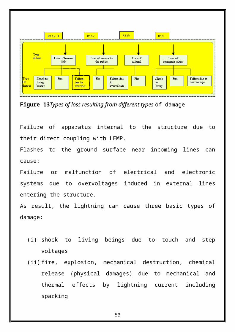
However, at that time the fight against electromagnetic noise did not yet use the term
electromagnetic compatibility.
The increase of electromagnetic problems for various electric and electronic installation
is related to the miniaturization of the electronic components which began in the 1950s
and 1960s. This miniaturisation, which was needed to reduce the weight of electronic
devices, is of course connected to the development of various sciences and in particular
to the use of satellites for military purposes. It increased the sensitivity of electronic
components and therefore, also probability of interference. Figure 9.1 shows the decrease
during the last 50 years of energy needed to destroy different kinds of electric and
electronic component. A constant decrease of the energy with a rather high slope can be
noted around the 1960s and 1970s.
The fact that much less energy was needed made the indirect lighting effects, e.g. the
electromagnetic fields due to the lighting discharge, one of the major threats for
electronics today.
Lightning as a disturbance source
In order to determine the potential danger that lightning can represent as a source of
disturbance, it is necessary to use the knowledge we have about the characteristics
lighting parameters. The important parameters to characterize the potentially of lighting
to become a source of interference are:
The lightning current value
The derivative of the lightning current
The energy contained in lightning discharge.
Characteristic values of the lightning discharge have been obtained by systematic
measurement of natural lightning. The most complete data on natural lightning is
probably that obtained by Berger [1] during more than 20 years of systematic recordings
on Monte San Salvatore in Switzerland. Lightning parameters are discussed in Chapter 3
of this book.
53

The Berger data and data obtained by other scientists have permitted us to construct the
probability curves of positive and negative lighting amplitudes shown in Figure 9.2 [2].
The main problem with this data is that it has mostly been recorded in the 1960s and
1970s, with technique which probably did not obtain the fastest of rise times due to
frequency limitation in the bandwidth. Another problem which modern techniques have
revealed is that in order to increase the chances of capturing lightning, towers as high as
possible have been used; new data has shown that the lightning current is reflected by the
ground and it is probable that the recordings of the 1960s and 1970s have been polluted
by these kinds of reflection, which could not have been observed with the technical
capability of the time [3].
When considering lightning as a source of disturbance, two aspects should be regarded:
(i) the direct lightning strike
(ii) the indirect effects due to the electromagnetic field created by the discharge.
In both cases, the two parameters mentioned previously stay at the basis of the
assessment. For the estimation of the indirect effects, more data is however necessary, as
discussed in other chapters. This is essentially the following:
the soil conductivity, which is the most important parameter as it determines the
value of the horizontal electric field component radiated by lightning channel
the geometry of the victim which will determine, as discussed in Chapter 7, the
value of the currents or voltages induced in the victim circuits.
These parameters are discussed in other chapters. As also discussed in Chapter 7, field-
to-transmission line coupling models today permit numerical estimation of the indirect
effects of lightning.
Using the existing measured data and other such approaches, and in spite of the probable
errors in the data and the approximations in the models, the existing knowledge has
permitted us to access the electromagnetic effects of lightning on circuits and
installations and develop protection concept and mitigation methods.
54

A) Types of coupling between lightning and circuits or installations
i) Coupling modes
In order to permit modeling, the coupling modes between a disturbance source and a
victim have been classified in different ways and under different criteria. One kind of
classification is shown in Figure 9.3 [4] and it is this approach which will be used in what
follows in order to discuss effects due to lightning. In this chapter, the following
definition of direct and indirect lightning effects will be used. The term direct effect will
be used only if a lightning strike hits an installation or a conductor galvanic ally
connected to the installation. The term indirect effect will be used in two kinds of
situation:
(i) When a nearby lightning stroke induces a current in an installation of a
conductor galvanic ally connected to the installation.
(ii) When a lightning current injected in a conductor or in a metallic structure
induces a current in a nearby circuit or installation or gives a voltage drop at the
input of an electronic circuit.
Figure 9. Classification of coupling modes [4]
ii) Effects due to conductive coupling
55
This means that only conductive coupling will generate direct lightning effects on installations, and all kinds of coupling mode can be at the origin of indirect lightning effects.

As stated in the above paragraph, in the case of conductive coupling both direct and
indirect lightning effects to be considered. The conductive or galvanic coupling is
defined as a direct penetration of a current into an installation. This current is initiated
by a direct lightning strike. It will produce two types of effect:
(i) a direct effect if the strike takes place on a conductor connected to the
installation
(ii) an indirect effect if the strike takes place on a conductor connected to the
installation previously, the potential differences created by this current will be
transmitted at the input of an electronic circuit.
The probability of a direct strike on an overhead conductor connected to installation
depends on the solution adopted in different countries for the construction of electric
supply or telecommunication lines. This probability is very low in urban areas and in
Europe where most of the distribution and telephone network is underground. In North
and South America, for historical reasons, most of the low-power electric distribution is
aerial even in towns. The same situation prevails in Japan where, due to the frequent
earthquakes, practically the whole energy and telephone network is constructed over the
ground: the repair of an underground circuit is much more expensive that that of aerial
one. In general a rural network is also built using overhead lines. For aerial networks
the probability of being hit by lightning is much higher. This probability can be
calculated based on the keraunic level of the region.
iii)Calculation of the average number of lightning strokes per year on a overhead
line
The average density of lightning strokes per year on the ground (lightning strokes per
km per year) can be calculated from the cherubic level of the region [5]:
Ns = Nk / 7 1/Km2 per year
Where Nk is the keraunic level or coefficient, i.e. the number of thunderstorm days per
year. A thunderstorm day is defined as a day during
56

which at least one lightning stroke has been observed at a given location. The world
keraunic level map is shown in Figure 9.4 [6].
As an example, for most regions of western Europe, Nk = 15-50 (except the northern
part which has a lower thunderstorm activity). This means that an average number of Nk
= 30 can be taken which gives an average density of
Ns = 4.3 lightning strokes/km2 per year.
The average number of lightning strokes on an overhead line per year can be calculated
with an empirical formula [6-8]:
Nl = Ns (b + 28H0.6) (1 – Sf). 10-1
Lightning strokes on 100 km of line, where Ns is the lightning stroke density on the
ground previously defined, b (in meters) the horizontal distance between the lateral
conductors of the three-phase line, H (in meters) is the line height and Sf the shielding
factor due to the presence of other nearby objects. For heights of several meters over
the ground, b is much smaller that
28H0.6 and can be neglected, eqn. (9.2) becomes:
Nl = 2.8Ns . H0.6 (1 – Sf)
Lightning strokes on 100 km of line. And for a line of length L:
Nl = 2.8Ns . H0.6 (1 – Sf) / 105
For western Europe with an Ns = 4.3 and an average shielding factor of 0.5 this gives
24 strokes per year on a distribution power line 10 m high and a length of 100 km.
Lightning current from a stroke on the ground can also arrive in an underground
structure such as a water or gas pipe. The probability for such a structure to collect
lightning current flowing in the ground due to a nearby discharge can be even higher
than for the line due to the larger surface around the structure on which the stroke can
occur.
57
These structures usually penetrate into buildings and are therefore, connected to the
grounding network of the construction. For security reasons all the electronic
installations inside the building are of course also connected to this grounding network.
The lightning current can in this way penetrate inside the installation. It should also be
noted that as grounding should usually have a low impedance, penetration of the
lightning current is facilitated in this way.
iv) Effects due to electromagnetic field coupling
Two kinds of mechanism can be at the origin of electromagnetic field coupling:
(i) a direct stroke on a building built in reinforced concrete and in which different
devices and circuits are installed
(ii) a lightning stroke near enough to the building in which sensitive devices are
installed to create an electromagnetic field which can induce dangerous
currents in the circuits of the installation.
1. Direct strokes on a building
If modern protection concepts are used, all the metallic parts of the building will be
connected and the lightning current will be distributed in the rebar of the construction.
This lightning current will create an electromagnetic field inside the building. Due to
the high current value flowing in the rebar’s, the magnetic field will be predominant.
The technique to triggering lightning with small rockets carrying a wire which brings
the lightning current to a chosen location has been used to strike the grounding rod of a
real telecommunication tower. The measurements have shown that if the earthing of the
tower is correctly achieved only 30 percent of the lightning current flows in the metallic
structure of the tower and rest into the ground. However, if the lightning strike hits the
top of a building and not its grounding rod the current will circulate in the whole
metallic structure. . Scale model measurements on a metallic cube of 2 x 2 x 2 m in
high voltage laboratory [9] show that a lightning current of about 1 kA peak value
58

creates a peak magnetic field of 20 A/m (Figure 9.5). In a loop of 1 m 2 a magnetic field
variation of 20 A/m on 10 µs can create an induced voltage of 2.5 V.
Other laboratory simulations [10] on a 2 x 2 x 2 m rebar cage (Figure 9.6a), show that
the current induced in a loop inside a metallic structure in which lightning current is
flowing can is some cases (depending on the position in the cage and the rebar density)
be higher than the current in the same loop but without the presence of the cage (Figure
9.6b) This is due to the high lightning current flowing in a rebar near which the
measurement loop was situated. This simulation shows that the solution of disturbing
the lightning current in the whole metallic structure of a reinforced concrete building
can be, from the immunity point of view, worse for some installations that the solution
of concentrating the discharge lightning current in a single descending conductor. These
installations should be, in such a case, correctly protected.
2. Lightning stroke near a building
The expression ‘near’ or ‘near enough’ are relative and depend on the amplitude and
derivative current and of its energy content. Measurement using triggered lightning
permit us to predict that lightning strokes at distances of about 50-500 m, with average
amplitudes of 30 kA and average di/dt values of 30 – 100 kA/µs, can induce currents of
tens of amperes in circuits forming a loop with a perimeter of a few meters [11]. Figure
9.7 shows the current measured in a line 8 m long and 1.8 m high and installed at 70 m
from the impact point of triggered lightning on the Camp Blanding site in Florida. The
measured value of the lightning current was equal to about 6 kA. It can be seen that the
induced current reached a peak value of 6 A. Assuming an attenuation of the
electromagnetic field of about 6-10 dB inside a reinforced concrete building, the
induced current amplitude in a circuit inside the building could be about 2-3 A which
would be real treat for any electronics connected to this circuit.
B) Typical EMC problems due to lightning
In this section we shall try to present a much summarized overview of different but
typical EMC problems which can be experienced in different kinds of electricity
application. These examples as far from being exhaustive but should give a good idea
59

of kinds of specific problem that can arise in the particular applications which will be
reviewed. Specific protection methods for each example will be briefly mentioned in
this section and then discussed in general
(d) Lightning effects in power networks
The best known effect of lightning in power transmission of distribution networks is the
direct lightning stroke either on a phase conductor or on a tower (or ground conductor).
The protection of HIV overhead lines against direct strikes is achieved by grounding
wires mounted on towers where the wire is grounded. Today, the danger of a direct
strike on a phase conductor is minimized by the presence of ground conductors for
transmission lines 125 kV and higher. However, there is a certain probability that
distribution lines of 60 kV and lower voltage could be hit by a direct lightning strike.
Another possible outage danger comes from the backlash or return arc which occurs if a
lightning stroke hits the grounding wire and the potential rise of the tower top exceeds
the insulation strength of the insulator chain. In this case an arc between the ground
wire and a phase conductor takes place injecting at least a fraction of the total lightning
current into the phase conductor (Figure 9.8).
Indirect lightning strokes, which can induce 50-60 kV or even higher overvoltages for
the case of a nearby lightning stroke (50 m from the line) with the relatively low peak
discharge current of 12 kA [12] should have little effect on power HV transmission
lines but could easily exceed the insulation strength of the distribution network causing
short circuits and disruption of the energy supply.
A recorded overvoltage on a 13kV distribution line Mexico due to a natural lightning
stroke of unknown amplitude and distance to the line.
Tests for protection efficiency on a real scale have been performed [14]. Lightning
currents triggered using the rocket launching techniques have been injected at the Camp
60
Blanding site Florida in a 730 m long overhead line. Several Metal-Oxide Varistor
arresters were installed on the line. The injected current and the arrester voltage .
In the cases discussed above, a direct strike of the line produces a galvanic coupling of
the interference, but with the indirect effect all three components (electrostatic,
inductive and radiation) enter the structure of the incident electromagnetic field, their
respective contribution depending on the distance between the strike location and the
line .
(e) Lightning effects on power network substation equipment
Here again direct and indirect lightning stroke effects can take place, related as
above to galvanic or electromagnetic field coupling. However, the direct galvanic
coupling acts on substation equipment through a chain of effects in a quite perverse
way. Figure 9.11 shows a typical configuration for a circuit used for information
transmission (data from equipment to the dispatching room, alarms, control). Two
devices, T which is a translator used to covert information given for instance by a
voltage or current transformer and A which is a receiver, are connected through a
shielded coaxial cable. The shield is connected at the two extremities to the metallic
box of the two devices which can be grounded or not. The substation ground is usually
a metallic mesh buried at 30 – 50 cm under the earth’s surface. Any lightning current
hitting an overhead line entering the substation will be conducted to the ground by the
arrester usually installed at the entrance of the substation. The large lightning current
flowing in the grounding mesh will create a voltage drop, U. If the equipment A is not
grounded, this voltage drop is found between A and the ground and this can be
dangerous for the safety of the personnel. If A is grounded, the voltage drop appears
between the internal conductor of the coaxial cable and the sheath, i.e. at the POE
(point of entry) of the electronics of equipment A.
Currents induced in common or differential mode in the substation circuits due to
indirect lightning effects also represents a large category of threats for sensitive
electronic components. Usual EMC protection measures like proper grounding or
61

bonding must be applied in order to avoid outages due to lightning in the power
network.
(f) Lightning effects on telecommunication networks:
The effects of lightning on telecommunication networks are quite similar to those
discussed for power networks, with the difference that telecommunication lines are
lower than power lines and in many cases buried; this decreases the probability of direct
strikes. However, the effects due to indirect lightning can be more dangerous as the
telecommunication equipment is more sensitive than that connected in a power
network. Figure 15 shown the results of a two-year lightning-induced overvoltage
measurement campaign in the French telecommunication network which has been
performed in five different sites in France: rural and urban, industrial and residential
and in regions with different thunderstorm activity [16]. By counting the number of
cases shown in Figure 15b, it can be seen that values 27 times higher than 2 kV have
been measured in a network designed for a supply of 48 V or for transmitting signals at
an even lower level. Protection of the telecommunications equipment installed inside
the switching entity is achieved by installing suppressors at the POE of the buildings or
of the sensitive equipment.
(g) Lightning effects on low-voltage power networks:
Less spectacular, the effects of a lightning stroke in the proximity of low voltage
power network supplying residential areas can be quite damaging in many cases.
Examples are not very often recorded, because they are mainly known to the insurance
companies and not to scientists or engineers and are not published. However, a few
cases can be referred to, like the destruction of all the TV sets in a residential building
on the heights of the town of Montereux in 1996 and the destruction of TV sets through
a current induced by a nearby lightning strike in the parabolic antenna of a big hotel in
the town of Lausbanne in 1997, both in Switzerland.
Figure 9.13 shows the statistics of overvoltages due mainly to lightning strokes in
different environments in Switzerland [17]. For comparison a composite curve for a 120
V distribution network in the USA is also shown.
62

Simulations of lightning-induced effects in the low-voltage network of residential
houses have been performed by current injection in Sweden [18]. And for aircraft
lightning immunity tests, the current injection was used as an approximation to assess
the immunity of the residential distribution system instead of field radiation testing
because of its low cost and high repeatability. The current injection was performed in:
Common mode between phase and ground
Differential mode between two phases of the three-phase domestic network.
Different transfer functions were tested and the example of Figure 9.14 shows the
transfer voltage factor between the load response and the injected voltage at the house
point of entry (POE).
(h) Lightning effects on aircraft
Aero planes are often hit by lightning. Thunderstorm clouds cannot always be
avoided by the aircraft and usually the plane forms a conducting bridge between two
charged thunderclouds triggering a lightning discharge which flows on the metallic
surface of the plane fuselage (Figure 9.15).
Two trends in modern technology have increased the need to consider carefully the
threat represented by lightning for an aircraft:
(i) the increase of sensitive electronics used in aircraft
(ii) The possible use of nonconductive or less conductive materials for the aero
plane body.
Both can be at the origin of EMC problems. In order to estimate the threat, experiments
with an instrumented aircraft flying inside thunderstorm have been performed and
currents induced by lightning discharges on the aero plane have been recorded at real
scale. Another way of estimating the threat and the protection level offered by the
metallic envelope represented by the plane fuselage has been achieved by injecting
pulses similar to lightning currents in an instrumented aircraft on ground [19]. These
studies have permitted specific standards to be written which define the test methods
the shape of the injected current and the test levels.
63

B. Specific EMC lightning protection parameters
(a) General
Protection measures against the direct effects of lightning on buildings and
relatively huge installations which are discussed in Chapter 8 must be combined and
coordinated with protection against direct or induced lightning effects on all kinds of
sensitive equipments. This means that specific EMC lightning protection concepts have
been developed and should be achieved. Lightning parameters which are important for
EMC are the general parameters which characterize the physical process of a lightning
discharge. In what follows they will be viewed from an EMC point of view with an
emphasis on protection against effects which can create disturbances to sensitive
circuits and equipment. The protection deals mainly with the primary lightning
conducted environment due to direct strikes. However, more and more consideration is
given to the secondary lightning conducted environment due to the indirect effect. As
an example, Table 9.1 [20] shows test lightning parameters corresponding to average
short circuit currents due to both the direct and indirect effects to be expected on an
overhead telephone subscriber line of 1 km length. Note that the lightning currents
which are given here as normed waveforms may be considerably different in practice.
Event Amplitude/
waveform
RemarksLightning stroke:
- direct stroke 30 kA/10 x 350 µs
- estimated average peak current
values at the end of the line
- indirect stroke 5 kA/8 x 20 µs - values may be 5-6 times higher
Table 4 Lightning current waveforms which can be used for tests.
An emphasis on protection against effect which can create disturbances to sensitive
circuits and equipments. The protection deals mainly with the primary lightning
conducted environment due to direct strikes. However, more and more consideration is 64

given to the secondary lightning conducted environment due to the indirect effect. As
an example, Table 9.1 [20] shows test lightning parameters corresponding to average
short circuit currents due to both the direct and indirect effects to be expected on an
overhead telephone subscriberline of 1 km length. Note that the lightning currents
which are given here as normed waveforms may be considerably different in practice.
As lines become shorter the probability of lightning surge occurrence goes down, but
directs strokes now have a higher probability of reaching the end of the line with all
their energy.
It should be mentioned that currents and voltages due to very fast transients like those
due to switches in GIS power networks, electrostatic discharges other various sources
of such kinds of interference always represent a certain probability for various
installation together with the lightning threats. Combined protection measures against
lightning and such very fast transients can be used. As EMC problems are usually
viewed as being generated by HF phenomena (i.e. fast transients), in the following such
combined protection measures are analyzed by looking at basic surge parameters on
long lines (L > 1 km) and by considering the consequences of the two threats. As the
very fast transient effect are very similar to high altitude EMP (HEMP) effects, the data
which will be used for the following comparison has been taken from the HEMP
literature, regarded here as representative for all kind of fast transient.
(i) Peak current
The peak current is only responsible for voltage drops on ohmic resistances, e.g.
the grounding resistance. In a direct lightning stroke the local ground potential of a
protected area may be raised by several hundred kV relative to a distant point. This may
result unpredictable dielectric breakdowns to ground in the protected area. The
phenomena are clearly limited to lightning events and to installations with an imperfect
shield or an unfavorable grounding system. In most cases the effect of di/dt on
inductive voltage drops is much more important.
(j) Peak current derivative
Inductive voltage drops and induced voltages are proportional to di/dt. In general,
it is this parameter that gives rise to the most and severest problems in all protection 65

concepts. For direct lightning strokes the di/dt value chosen for the protection concept
may be as high as 100 – 200 kA/µs. For fast transients this parameter may attain values
as high as 150 kA/µs. Although sometimes higher that for lightning, it is still of the
same order of magnitude and can be addressed with the same conceptual methods.
(k) Peak rate of change of voltage
Peak rate of change of voltage may only be applied to surge protectors with great
precaution. Voltage rise times given in the literature are based on coupling calculations
assuming certain field or current waveforms and linear line parameters. The theoretical
peak voltage level may be as high as several 100 kV or even in the MV range for
lightning. Typical values are in the range of 100 kV/µs-1kV/ns for lightning and 1-10
kV/ns for fast transients. One does not usually consider nonlinear effects like insulation
breakdown and firing actions of gas filled surge arresters which may occur in the sub
nanosecond range even in the course of a lightning event. One also neglects ionization
effects and line losses in the 100 MHz frequency range. Assuming a low-pass
characteristic for the line, the maximum du/dt will occur somewhere near half. There is
no doubt that du/dt at lower levels (most primary protection elements switch from the
insulating into the conducting state well below 10 kV) is smaller than (du/dt)max. This
uncertainty is mostly due to unsufficient calculating models for frequencies above 100
MHz and a limited knowledge of nonlinear line parameters.
(l) Total charge
Total charge can be obtained by integrating the measured current. Values vary
from 50 x 10-6 A for fast transient to 70 A in a very powerful direct lightning stroke. As
most voltage breakdown and voltage limiting devices exhibit a distinct voltage
stabilizing action (a very low impedance above a typical threshold voltage), their
current carrying capability may approximately be described in terms of the integral i x
dt. An 8 x 8 mm gas filled arrester is about equally stressed by an indirect lightning
stroke of 12 kA, 8/20 µs and by another type of fast transient.
The action integral: integral i2 x dt
The action integral is a parameter which is proportional to the energy. It has the units
A2 s = J/۰; and it gives the energy that would be absorbed in a resistance of 1 Ω range, 66

they absorb only a comparatively small part of the potential energy. The capacity for
energy absorbance of a surge arrester is therefore not relevant for its quality. The
integral i2 x dt is several thousands times higher in a lightning stroke than in different
fast transients. It is relevant for thermal effects in ohmic resistances, e.g. current
carrying capability of cable wires, and magneto-dynamic effects in current loops. Short
powerful current surges (for example: 40kA, 8/20 µs) may mechanically destroy an 8 x
8 mm gas filled protector before it is thermically destroyed.
Time to half value of the current
The time to half value of the current waveform is one of the most important
determinants for protection circuits, i.e. combinations of primary and secondary
protection elements. It varies from about 100 ns for fast transient to 350 µs in a direct
lightning stroke.
Conclusion on LEMP and fast transients protection comparison
Except for du/dt lightning represents a more severe threat than any other kind of fast
transient as far as conducted disturbance is concerned. However, we must also consider
the possible degradation of the shield attenuation by installing protection devices
against conducted disturbance. For economic reasons and because a radiation shield is
missing in most cases, lightning protection elements are usually not designed as feed
through elements. They will therefore, degrade the shield attenuation of a shielded
protection concept unless special care is taken in their installation. The most important
rule to observe is that the surge current should not radiate into the protected zone. This
can be achieved by installing at least the primary protection element outside the shield
or by adding a supplementary.
Assuming that an installation is correctly done, then a well designed only lightning
protection concept may be completed into a lightning + fast transient concept at almost
no additional cost. An only fast transient concept should be chosen unless the lightning
threat can be completely excluded.
67

Conclusions:
This project is very rare since we can not test lightning in the lab. As in this project we
emphasis about types of lightning , ground flash density in USA and Saudi Arabia ,and
how to protect of lightning and study case about overhead lightning on transmission
line, and EMC(electromagnetic compatibly ). we can expect to see many more lightning
storms in parts of the country where there is the potential for large amounts of moisture
to be carried to great heights and cooled rapidly, such as the of the Saudi Arabia, U.S.
This theory seems to fit the known facts of thunderstorms and in fact predicts them. It is
a good model and seems to hold true to the conditions that we observe relating to
lightning. It is the only theory that fits the signature and characteristics of lightning
from its birth in the oceans and quiet ascension into the heavens to its fiery and noisy
return to earth again. We hope that this primer is useful in explaining for this lightning.
References:
68

1. Brownian Motion at
http://www.sciences.demon.co.uk/wbbrowna.htm
2. Brownian motion simulations at
http://www.phy.ntnu.edu.tw/java/gas2D/gas2D.html
and http://www.phys.virginia.edu/classes/109N/more_stuff/Applets/brownian/
brownian.html
3. Atoms at http://www.fourmilab.ch/autofile/www/section2 14.html
4. A Lightning Primer at http://thunder.msfc.nasa.gov/primer/
5. Polarisation at
http://www.netzmedien.de/software/download/java/polarisation/index.html
6. Lightning Safety Tips
http://www.lightningsafety.com/nlsi_pls/lst.html
7. Lightning simulations at
http://www.sciencejoywagon.com/physicszone/lesson/07elecst/lightnin/
lightnin.htm
and http://www.uccs.edu/ physics/simulations/lightning.html
8. Interlude VI of "Physics" by Ohanian, Second Edition, Norton and Company,
1989.
9. Conducting polymers at
http://homepage.dtn.ntl.com/colin.pratt/applcp.htm
10. Golde, R.H., Lightning Protection, 1973.
11.IEEE Standard 1100, IEEE Recommended Practice for Powering and Grounding
Sensitive Electronic Equipment (Emerald Book), 1999.
12.IEEE Standard 142, IEEE Recommended Practice for Grounding of Industrial
and. Commercial Power Systems (Green Book), 1991.
13.Military Handbook 419A, Volumes I & II, Grounding, Bonding and Shielding,
Department of Defense, 1987.
14.Military Handbook 464, Electromagnetic Environmental Effects, Department of
Defense, 1997.
15.National Fire Protection Association 70, National Electrical Code, NFPA, 1999.
69

16.National Fire Protection Association 780, Standard for the Installation of
Lightning Protection Systems, NFPA, 1997 & 2000.
17.Uman, Martin A and Krider, E. Philip, “Natural and Artificially Initiated
Lightning,”SCIENCE, 27 October 1989, Volume 246, pp. 457-464.
18.“High voltage engineering” final year lecture notes, Prof. J.R. Lucas
19. IEEE transaction on power delivery, vol. 4, No 1, January 1989. Analysis of
lightning induced voltages on overhead lines, P. Chowdhuri, senior member.
20. IEE Proc., vol 127.Pt. C. No 1, January 1980. Experimental analysis of earth
wires for induced lightning surges, S. Yokohama, B.E.
21. IEEE transaction on power delivery, vol....PWRD-1, No. 2, April 1986.
Extension of the Chowduri –Gross model for lightning induced voltage on
overhead lines, A.C. Liew and S.C. Mar.
22. IEEE transaction on power delivery, vol. 10, No 1, January 1995. Comparison of
two lightning models for lightning induced. Overvoltage calculations, C.A.
Nucci, F. Rachidi & C. Mazzetti
23. Lightning protection of pole mounted transformers and its applications in Sri
Lanka, Prof. J.R. Lucas & D.A. Nanayakkara.
24.IEEE transmission and distribution conference, Panel session “Distribution
Lightning Protection”, New Orieans, April 14, 1999. Lightning Induced Over
voltages, C.A. Nucci & F. Rachidi.
25.) IEE Proc., vol. 129. Pt. C., No 2, March 1982. Lightning performance and
overvoltage surge studies on a rural distribution line, A.J. Eriksson & D.V. Meal.
26. Book “the lightning Flash” by Vernon Cooray
27. “Insulation Coordination for Power Systems” by Andrew
70