Introduction - ecs.umass.edu€¦ · Web viewIn the end, Mapper is able to remotely traverse the...
12
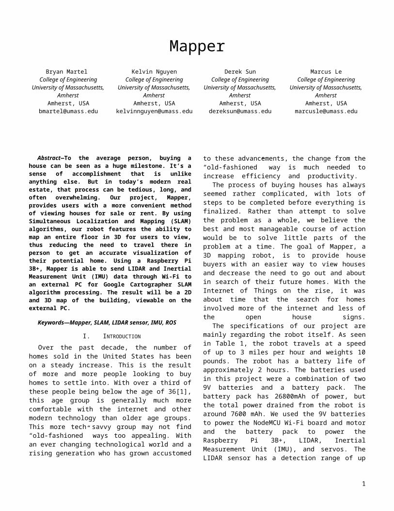
Mapper Bryan Martel College of Engineering University of Massachusetts, Amherst Amherst, USA [email protected] Kelvin Nguyen College of Engineering University of Massachusetts, Amherst Amherst, USA [email protected] Derek Sun College of Engineering University of Massachusetts, Amherst Amherst, USA [email protected] Marcus Le College of Engineering University of Massachusetts, Amherst Amherst, USA [email protected] Abstract—To the average person, buying a house can be seen as a huge milestone. It’s a sense of accomplishment that is unlike anything else. But in today’s modern real estate, that process can be tedious, long, and often overwhelming. Our project, Mapper, provides users with a more convenient method of viewing houses for sale or rent. By using Simultaneous Localization and Mapping (SLAM) algorithms, our robot features the ability to map an entire floor in 3D for users to view, thus reducing the need to travel there in person to get an accurate visualization of their potential home. Using a Raspberry Pi 3B+, Mapper is able to send LIDAR and Inertial Measurement Unit (IMU) data through Wi-Fi to an external PC for Google Cartographer SLAM algorithm processing. The result will be a 2D and 3D map of the building, viewable on the external PC. Keywords—Mapper, SLAM, LIDAR sensor, IMU, ROS I. INTRODUCTION Over the past decade, the number of homes sold in the United States has been on a steady increase. This is the result of more and more people looking to buy homes to settle into. With over a third of these people being below the age of 36[1], this age group is generally much more comfortable with the internet and other modern technology than older age groups. This more tech savvy group may not find “old-fashioned” ways too appealing. With an ever changing technological world and a rising generation who has grown accustomed to these advancements, the change from the “old-fashioned” way is much needed to increase efficiency and productivity. The process of buying houses has always seemed rather complicated, with lots of steps to be completed before everything is finalized. Rather than attempt to solve the problem as a whole, we believe the best and most manageable course of action would be to solve little parts of the problem at a time. The goal of Mapper, a 3D mapping robot, is to provide house buyers with an easier way to view houses and decrease the need to go out and about in search of their future homes. With the Internet of Things on the rise, it was about time that the search for homes involved more of the internet and less of the open house signs. The specifications of our project are mainly regarding the robot itself. As seen in Table 1, the robot travels at a speed of up to 3 miles per hour and weights 10 pounds. The robot has a battery life of approximately 2 hours. The batteries used in this project were a combination of two 9V batteries and a battery pack. The battery pack has 26800mAh of power, but the total power drained from the robot is around 7600 mAh. We used the 9V batteries to power the NodeMCU Wi-Fi board and motor and the battery pack to power the Raspberry Pi 3B+, LIDAR, Inertial Measurement Unit (IMU), and servos. The LIDAR sensor has a detection range of up 1
Transcript of Introduction - ecs.umass.edu€¦ · Web viewIn the end, Mapper is able to remotely traverse the...
MapperBryan Martel
College of EngineeringUniversity of Massachusetts,
AmherstAmherst, USA
Kelvin NguyenCollege of Engineering
University of Massachusetts, Amherst
Amherst, [email protected]
Derek SunCollege of Engineering
University of Massachusetts, Amherst
Amherst, [email protected]
Marcus LeCollege of Engineering
University of Massachusetts, Amherst
Amherst, [email protected]
Abstract—To the average person, buying a house can be seen as a huge milestone. It’s a sense of accomplishment that is unlike anything else. But in today’s modern real estate, that process can be tedious, long, and often overwhelming. Our project, Mapper, provides users with a more convenient method of viewing houses for sale or rent. By using Simultaneous Localization and Mapping (SLAM) algorithms, our robot features the ability to map an entire floor in 3D for users to view, thus reducing the need to travel there in person to get an accurate visualization of their potential home. Using a Raspberry Pi 3B+, Mapper is able to send LIDAR and Inertial Measurement Unit (IMU) data through Wi-Fi to an external PC for Google Cartographer SLAM algorithm processing. The result will be a 2D and 3D map of the building, viewable on the external PC.
Keywords—Mapper, SLAM, LIDAR sensor, IMU, ROS
I. INTRODUCTION
Over the past decade, the number of homes sold in the United States has been on a steady increase. This is the result of more and more people looking to buy homes to settle into. With over a third of these people being below the age of 36[1], this age group is generally much more comfortable with the internet and other modern technology than older age groups. This more tech savvy group may not find “old-fashioned” ways too appealing. With an ever changing technological world and a rising generation who has grown accustomed to these advancements, the change from the “old-fashioned” way is much needed to increase efficiency and productivity.
The process of buying houses has always seemed rather complicated, with lots of steps to be completed before everything is finalized. Rather than attempt to solve the problem as a whole, we believe the best and most manageable course of action would be to solve little parts of the problem at a time. The goal of Mapper, a 3D mapping robot, is to provide house buyers with an easier way to view houses and decrease the need to go out and about in search of their future homes. With the Internet of Things on the rise, it was about time that the search for homes involved more of the internet and less of the open house signs.
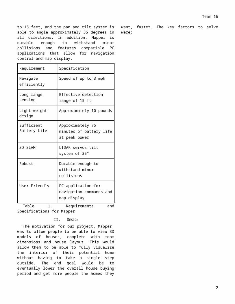
The specifications of our project are mainly regarding the robot itself. As seen in Table 1, the robot travels at a speed of up to 3 miles per hour and weights 10 pounds. The robot has a battery life of approximately 2 hours. The batteries used in this project were a combination of two 9V batteries and a battery
pack. The battery pack has 26800mAh of power, but the total power drained from the robot is around 7600 mAh. We used the 9V batteries to power the NodeMCU Wi-Fi board and motor and the battery pack to power the Raspberry Pi 3B+, LIDAR, Inertial Measurement Unit (IMU), and servos. The LIDAR sensor has a detection range of up to 15 feet, and the pan and tilt system is able to angle approximately 35 degrees in all directions. In addition, Mapper is durable enough to withstand minor collisions and features compatible PC applications that allow for navigation control and map display.
Requirement Specification
Navigate efficiently Speed of up to 3 mph
Long range sensing Effective detection range of 15 ft
Light-weight design Approximately 10 pounds
Sufficient Battery Life Approximately 75 minutes of battery life at peak power
3D SLAM LIDAR servos tilt system of 35°
Robust Durable enough to withstand minor collisions
User-Friendly PC application for navigation commands and map display
Table 1. Requirements and Specifications for Mapper
II. DESIGN
The motivation for our project, Mapper, was to allow people to be able to view 3D models of houses, complete with room dimensions and house layout. This would allow them to be able to fully visualize the interior of their potential home without having to take a single step outside. The end goal would be to eventually lower the overall house buying period and get more people the homes they want, faster. The key factors to solve were:
1. Integrating the LIDAR system with a 3D SLAM Algorithm
1
Team 16
● Record and store LIDAR and IMU sensor data● Establishing wireless communication that allows the
robot to send back LIDAR and IMU data for SLAM algorithm processing
● Creating a visual 2D and 3D map from LIDAR sensor measurements
2. Allowing for user input controls to control the robot over a wireless network
● Integrating motors to allow for robot/sensor maneuverability
● Establishing Wi-Fi connectivity to allow the user to control the robot
● Provide live video feedback from the robot to user
These two main ideas were broken down further into blocks that could all be worked on simultaneously and
independently. This section will explain the in-depth process our team went through to design and create Mapper. It goes over the individual blocks pertaining to Mapper, explaining what was done, and all the steps that were taken. There will also be a section on project management that details the structure and functionality of our team, the roles that each of the team members play, and the status of all of our FPR deliverables. There is also a schedule outlining when each part of our project was being worked on and when they were completed.
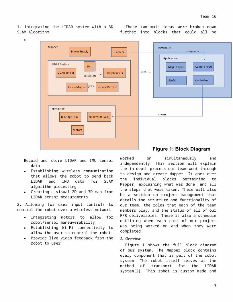
A. OverviewFigure 1 shows the full block diagram of our system. The
Mapper block contains every component that is part of the robot system. The robot itself serves as the method of transport for the LIDAR system[2]. This robot is custom made and includes a hollow inside for wiring, circuitry, and power supplies. In the Mapper block, we have the LIDAR System and the Navigation system. In the LIDAR System, the LIDAR sensor and IMU send data to the Raspberry Pi 3 B+, which uses its internal Wi-Fi capability to relay that data back to the PC. There is also an automated pan and tilt servos system that is controlled by the Maestro and runs in a preset, repeating pattern. In the Navigation system, we have the NodeMCU that takes in user commands through Wi-Fi to drive the motors through our custom PCB. The external PC block includes the PC application used to run SLAM [4], view Mapper’s live video feed, and provide user input controls to the robot.
B. RobotThe two main components of the robot body includes the
lid and the chassis. The lid is responsible for providing a flat surface to mount any external components, such as the servos motors with the servos mount and the LIDAR and LIDAR mount. The main chassis is responsible for housing the internal components, such as the battery, the motors, the PCB board, and any other accessories needed. Along with housing internal components, the chassis is responsible for holding the phone mount that houses the Android phone.
The lid of the robot is a circular piece of wood, 13 inches in diameter and ½ inch thick, that is screwed down onto the
2
Team 16
chassis. This part was made out of wood, since precisely shaping wood is much easier than shaping any other materials. In addition to that, it is durable enough to withstand minor collisions. The lid is primarily responsible for providing a flat and stable surface onto which the servos motors with the servos mount can be attached.
In addition to the lid and the chassis, there were 3D printed mounts for the LIDAR, phone, and servos. We decided to 3D print our mounts because the parts are fairly intricate and require high accuracy in order to function properly. Also, 3D printing does not require the use of multiple tools in order to manufacture the mounts. This saves both time and money in producing the pieces we needed, efficiently and accurately.
Figure 2: Completed Mapper with Phone Mount (green) and Servos Mount (red)
C. NavigationThe navigation component of our robot consists of the two
Roomba motors and a camera. The two motors control each of our robot’s wheels and provides the robot with three main movement types. Before we get into the movement types, it is necessary to understand how the DC motors of the Roomba function.
There are two terminals to the motor, let’s call it terminal A and terminal B. When a large enough voltage drop is applied to the motor, the wheel rotates in a direction controlled by the polarity of the voltage. For the motors used, a voltage of anywhere between 9-18V is considered safe and feasible. If the voltage applied to terminal A is positive, and the voltage applied to terminal B is negative, the wheel will move in a forward direction. Alternatively, if the voltage applied to terminal A is negative and the voltage applied to terminal B is positive, the wheel will move in a backwards direction.
The speed of robot can be altered in two main ways. The first method is to vary the motor supply voltage. An increase in voltage applied gives the motors more power, resulting in a faster turning wheel. The other, more preferable method is to use a PWM signal that enables the motor terminals to turn on or off. By giving a motors a signal with less duty cycle, the percentage of the time in a clock period where the enable is
high is lessened, making the wheel turn off for a longer fraction of time and resulting in slower moving wheels.
With this in mind, let us now proceed to the two types of robot movement that Mapper features. As seen in Figure 3, the robot is able to move forward or backwards and can rotate left or right.
Figure 3: Robot Movement1. Forward/Backwards
The first movement type our robot features is the ability to move forward and backwards in a precise manner. This is done by ensuring that both wheels have the same voltage polarities across the motor. This allows the wheels to travel in the same direction. Next, we also have to ensure that the PWM signal that both motors get have the same duty cycle. The goal with this step is to have the wheels turn at the same speed. Little differences in the duty cycle may eventually lead to the robot veering off to the side.
2. RotationThe second movement type in the robot is the ability to
rotate clockwise or counter-clockwise in place. The idea here is to allow the robot to take 90 degree turns, or turn around completely. This is done by ensuring that the motors of each wheel have opposite polarity, resulting in one forward turning wheel and one backwards turning wheel. It is also important that both motors receive the same PWM signal, as to keep their speeds the same. Determining which wheel is the forward moving wheel will affect whether the robot moves clockwise or counter-clockwise.
D. Video FeedWhile running the scan, the user needs to be able to
navigate the robot properly without running into any walls. Since the user is most likely going to be in a separate room as to not be caught in the scan, a video feed is required to accurately navigate Mapper. A HTC 10 mobile phone running an off-the-shelf IP Webcam application is used to provide the live video feed. With this live video feed from the camera, the user is provided with a clear view of everything that is in front of Mapper.
E. NodeMCUNavigation commands are sent over WiFi to our onboard
NodeMCU chip. This development board is wirelessly connected to our external PC application and listens for UDP packets sent to its IP address. The board is powered by a 9V
3

Team 16
battery independent from our other power solutions. This was done to prevent instabilities that were encountered when the power supply was linked to other components. The UDP messages contain the motor output values in a range of 0-1024 to designate the speed of each motor. If no signal is received after one second, the robot stops to prevent unwanted movement. The PWM signals are output to the H-bridge to drive the motors as specified in the navigation section above.
F. LIDAR SystemThe LIDAR system is comprised of three main parts, the
RPLIDAR A2[6], the Sparkfun 9DoF Razor Inertial Measurement Unit (IMU)[7], and the two servos. These components are held together with a custom 3D printed mount.
The LIDAR sensor detects distances by firing out lasers and measuring the time it takes for them to bounce back. The specific model we used rotates 360 degrees at approximately 600 RPM to detect distances in all directions surrounding the sensor. The output of the LIDAR sensor is angle in degrees and distance in millimeters.
The Sparkfun IMU utilizes three sensors: accelerometer, gyroscope, and magnetometer. Using these three sensors, the IMU is capable of detecting linear motion, angular rotation velocity, and magnetic field vectors. While the magnetic field vectors are not particularly necessary, the linear motion and angular rotation velocity measurements are essential inputs to our SLAM algorithm.
For our pan and tilt system, we used two Tower Pro MG996R[8] Motors. These servos allow our LIDAR system to angle itself in order to measure the environment all around the robot. Without a pan and tilt servos system, the LIDAR sensor would only be able to scan a single slice of the room it is in. By having the LIDAR sensor scan at different angles, the sensor is able to pick up much more detail about the 3D layout of the room and thus generate our 3D map. The IMU provides us with information about the orientation of the LIDAR sensor as the system is panning and tilting.
The custom mount that we have designed, shown in figure 4, connects all these pieces together. The LIDAR sensor is mounted on the top of the mount, the IMU is embedded in a cavity in the mount below the LIDAR, and the bottom of the mount is attached to the servos system. This system is then attached to the lid of our robot.
Figure 4: LIDAR MountThe Raspberry Pi 3B+ is used to relay the sensor data back
to the external PC. The Raspberry Pi is running Ubuntu Server 18.04 and has Robot Operating System (ROS) installed on it. ROS is a set of software libraries and tools that help in building robot applications. The LIDAR sensor and IMU are both integrated into ROS and are able to publish their data in the appropriate ROS format. We are taking advantage of ROS’ distributed computing environment to enable the Raspberry Pi to remotely launch the sensors and publish the sensor data to the external PC over Wi-Fi. With the published sensor data, the external PC is then able to run this data through the Google Cartographer SLAM algorithm and generate a 2D and 3D map.
This system was first tested by bypassing the wireless data transfer aspect and connecting our sensors directly to the external PC. Initially, we tested the LIDAR and IMU separately using the sample software provided by the manufacturers. This was done in order to ensure the parts we received were not faulty and were able to produce the expected output. The LIDAR sensor is capable of accurate detection with +/- 1 millimeter of error. The IMU is far noisier and provides and output of +/- 10 degrees in its angular measurements.
G. External PCThe external PC is the brain of the project. It is responsible
for providing the robot with navigation instructions and processing the gathered sensor data. Navigation instructions are transferred from the PC to the robot through the NodeMCU Wi-Fi board. As shown in figure 5, the PC application interface consists of four navigation buttons, two motor speed settings, a set NodeMCU IP address, a set mobile phone IP address, and a checkbox to toggle the video feed
4

Team 16
display.
Figure 5: PC Application Interface
All data being collected by the sensors are recorded to a ROS bag file and published to the external PC’s ROS server. By recording all the sensor data to the bag file, we are able simulate a previous run again as though it were happening live. This is especially useful for making adjustments to our SLAM algorithm and being able to see the difference without collecting potentially anomalous data.
SLAM stands for Simultaneous Localization and Mapping, and is the core complexity of our project. SLAM takes in data from rangefinders and odometry in order to generate a map of its environment, while being able to locate itself within the map. The SLAM algorithm used by Mapper is the Google Cartographer SLAM algorithm[4]. This algorithm was selected due to its ability to conduct SLAM in both 2D and 3D. Being able to implement SLAM in two-dimensions allows us to better isolate any issues we encounter and allows for a more gradual development cycle.
III. PROJECT MANAGEMENT
FPR Deliverables Status
Component integration● Functional PCB
integrated into Mapper
● All hardware and circuitry fits neatly in Mapper
CompletePCB is a functional H bridge and is integrated into the rest of our system. Housings for LIDAR system, Android phone, and servos were 3D printed. All components are integrated and placed in the appropriate location on the interior or exterior of the robot.
Wireless maneuverability of robot
● User controls sent through Wi-Fi to Mapper
● LIDAR and IMU sensor data relayed back to PC
● Camera feed sent back to PC
CompletePC application is complete and functional. We are able to send navigation inputs to the robot’s motors through our PC application. Android phone is mounted on the front of the robot and provides a 640x480 live video feed. Raspberry Pi 3B+ relays sensor data to PC.
3D SLAM● 2D map generated
and viewable in Rviz
● Point cloud viewable in Meshlab
● Mesh generated from point cloud
Complete2D and 3D SLAM are both implemented. Generated 2D map is accurate and exportable. Generated 3D point cloud is relatively accurate, but needs manual touch up to be functional as a 3D map. Mesh can be generated over the point cloud to resemble a solid room.
Table 2. Status of FPR Deliverables
In terms of FPR deliverables, we have accomplished all promised deliverables and thus completed our project. Table 2 shows the status of all of our deliverables at the conclusion of our SDP project.
All components of our robot are integrated into the robot chassis. The LIDAR system mount. Android phone mount, and servos mount were all 3D printed and attached to the appropriate location on our robot. The PCB is functional and integrated into the robot’s interior. The PCB performs the same function as a H bridge and controls our robot’s two motors.
The robot is remotely operable through the use of a NodeMCU Wi-Fi board, Raspberry Pi 3B+, and Android phone. The NodeMCU takes user input from our PC application and controls the robot’s motors. The Raspberry Pi 3B+ relays our sensor data to our PC. The Android phone provides a live video feed for our PC application.
5

Team 16
The LIDAR sensor provides accurate laser distance measurements, and the Inertial Measurement Unit (IMU) provides relatively accurate orientation measurements. The data from these two sensors are the input to the Google Cartographer Simultaneous Localization and Mapping (SLAM) algorithm. Our implementation of 2D and 3D SLAM are both complete. The generated 2D map is accurate and is viewable in Rviz, a ROS visualization software. Once the 2D map is complete, it can be exported as a PNG or JPG file. As mentioned in the design section, the pan and tilt system enables us to gather distance measurements all around the robot, instead of just a 2D plane. The 3D point cloud is generated at the end of the run in .ply format and is viewable in Meshlab or any other 3D visualization program. As a demonstration of Mapper’s capabilities, we have included a run through one of Lewis Hall’s classrooms. Figure 6 shows the 2D map that is generated live while Mapper is in operation. This map displays black as known walls or obstacles and white as known open space. Grey areas are unknown and need to be scanned more in order to create a sufficient map.
Figure 6: Generated 2D Map of Lewis Hall’s Classroom
Figure 7 shows a real image of the Lewis Hall classroom, and figure 8 shows the point cloud generated by Mapper of that area. The couch and doorway can be clearly seen as
Figure 7: Image of one side of Lewis Hall’s Classroom
Figure 8: Generated Point Cloud of Lewis Hall’s Classroom
Figures 9 and 10 show an example mesh generated from the point cloud. This mesh was generated using the Poisson surface reconstruction algorithm from within the Meshlab program. While they are not perfect by any means, it shows that accurate 3D modelling is possible utilizing Mapper for interior environments. With further post-processing and a more refined algorithm, smooth surfaces can be generated and used in conjunction with images to accurately represent a room to a buyer.
Figure 9: Generated Mesh of Lewis Hall’s Classroom
6

Team 16
Figure 10: Top-down View of Mesh of Lewis Hall’s Classroom
Overall, we have achieved all of our goals for Mapper and thus completed our Senior Design Project.
A. Team
The team has been working and communicating efficiently. For each major component of our project, we generally break up the component into individual tasks. When assigning these tasks, each team member has an area of expertise that we take into consideration. The area of expertise of each individual team member is as follows:
Kelvin Nguyen (ME) - mechanical componentsMarcus Le (EE) - circuitsBryan Martel (CSE) - programmingDerek Sun (CSE) - programming
We have split our project into two major subsections: the robot and the SLAM mapping. As a result, we have informally divided our team into groups of two with Kelvin Nguyen and Marcus Le working together on the physical robot, and Bryan Martel and Derek Sun working together on the SLAM mapping. These teams are not exclusive, and we try to help each other to the best of our abilities.
B. Communication
In terms of responsibilities and communication, all team
members are expected to be accessible and easy to reach. Derek Sun is the team manager and is responsible for handling general team logistics, communications with our advisor and other faculty, and ensuring deadlines are met. Above all, each individual is responsible for finishing their assigned tasks in a timely manner. We have a group chat in order to make discussing Senior Design Project related things easier. We also have a voice chat server for when we need to discuss something, but are unable to meet up in person. Our team meets in person at least once a week, more so if there’s an important deadline coming up. During these team meetings,
7

Team 16
we go over our progress and review our deadlines and goals. We also try our best to meet with our advisor, Professor Ganz, at least once a week to update her on our progress and listen to any ideas or advice she has for us. When discussing a topic amongst the team, we make sure to keep an open-mind and be respectful. All conflicts in ideas are resolved through discussion as a team.
C. Project Schedule
The key events in our Gantt chart are 3D SLAM and integration of our components. We found that 3D SLAM required the most time of all of our tasks. Because of that, we allocated a large chunk of time to it. The integration of all components was vital to the success of our final project. Thus, we spent the rest of the semester following CDR working on getting all the components properly working and integrated.
IV. CONCLUSION
Using a LIDAR Sensor in parallel with an inertial measurement unit, servos motors, and a 3D slam algorithm, we were able to map an entire room in 3D and present the user with a display that was clear and accurate. Many other components used in the project served as necessary tools to aid in the LIDAR system’s overall success. These tools included a phone camera for user navigation, Wi-Fi module for robot commands, and a Raspberry Pi 3B+ for data transmission. In addition, a servos module was automated for continuous LIDAR sensor panning and tilting. Altogether, each individual subsystem played an impactful role in Mapper’s completion. Looking back at the project, most of the time was spent working in parallel developing each of the subsystems. It wasn’t until after MDR where we worked on integrating each all the subsystems together. Since MDR, we have completed the Wi-Fi communication that Mapper uses to maneuver via user input commands, as well as the data transfer of the LIDAR sensor and IMU data from Mapper to the external PC. To transmit user commands over Wi-Fi, we used the NodeMCU Wi-Fi development board. With its limited bandwidth and relatively low reliability, we decided to use a separate system for the LIDAR and IMU data transfer. We decided on a Raspberry Pi B+, which was placed in Mapper to wirelessly relay the sensor data from Mapper back to the PC. We also worked on refining the 2D and 3D mapping. In the end, Mapper is able to remotely traverse the room and present a live video feed and 2D map to the user’s external PC. Once the scan is finished, a 3D map in point cloud or mesh form can be generated and exported for viewing. Potential future applications of the maps generated by Mapper could include virtual reality tours and search and rescue.
ACKNOWLEDGMENT
Special thanks to:Prof. Aura Ganz for being our advisor and guiding us
through technical and non-technical aspects of our projectShira Epstein for providing thoughtful insight regarding
SLAM and possible problems to look out for
Prof. Jun Yao for his helpful evaluation and supportDr. Chengbo Ai for his advice regarding LIDAR systemsFrancis Caron for ordering the parts we needed and
getting them to us as quickly as possible
REFERENCES
[1] “Home Buyer and Seller Generational Trends,” www.nar.realtor. [Online]. Available: https://www.nar.realtor/research-and-statistics/research-reports/home-buyer-and-seller-generational-trends.
[2] Cdn.sparkfun.com. (2019). [online] Available at: https://cdn.sparkfun.com/assets/e/a/f/9/8/LD208_SLAMTEC_rplidar_datasheet_A2M8_v1.0_en.pdf
[3] Module, L. and Module, L. (2019). Left Wheel Module. [online] Store.irobot.com. Available at: https://store.irobot.com/default/parts-and-accessories/roomba-accessories/700-series/left-wheel-module/83201.html
[4] “Cartographer,” Cartographer - Cartographer documentation. [Online]. Available: https://google-cartographer.readthedocs.io/en/latest/.
[5] Store.arduino.cc. (2019). Arduino Nano. [online] Available at: https://store.arduino.cc/usa/arduino-nano
[6] Scanner, R. (2019). RPLIDAR A2M8 360° Laser Range Scanner - SEN-14756 - SparkFun Electronics. [online] Sparkfun.com. Available at: https://www.sparkfun.com/products/14756.
[7] M0, S. (2019). SparkFun 9DoF Razor IMU M0 - SEN-14001 - SparkFun Electronics. [online] Sparkfun.com. Available at: https://www.sparkfun.com/products/14001
[8] towerpro.com. (2019). MG996R | Torq Pro & Tower Pro. [online] Available at: http://www.towerpro.com.tw/product/mg996r/
[9] IP Webcam Android Application. Available at:https://play.google.com/store/apps/details?id=com.pas.webcam&hl=en_US
8