INTRODUCTION - City Utilities of Springfield · INTRODUCTION City Utilities of ... reliable, and...
38
Page 4 INTRODUCTION City Utilities of Springfield is dedicated to helping customers achieve optimum value from their electrical service. To accomplish this, City Utilities must effectively utilize its production and supply capabilities, while ensuring safe, reliable, and consistent electric service. Experience has shown that uniform standards for installation, wiring, and system design are the best way to accomplish these goals. The Electric Service Standards are not intended to be restrictive or burdensome, but to assist in expediting service connections and establishing appropriate customer classifications for service and billing. It is necessary for customer wiring and installation intended for connection to City Utilities of Springfield electric system to comply with the Electric Service Standards contained herein, the National Electrical Code, the National Electric Safety Code, City of Springfield Department of Building Development Services regulations, Greene County Building Regulations requirements, and any other codes or regulations in effect in the area served. This document is offered to assist customers, architects, engineers, contractors, electricians, and inspectors in planning electric service installations. It is not intended to ensure adequacy and safety of the customer’s wiring and equipment; such responsibility remains with the customer. City Utilities does not inspect the customer’s wiring for compliance with requirements of electrical codes or regulations established by inspection authorities. Inspection authority is the responsibility of the City of Springfield Department of Building Development Services, Greene County Building Regulations or other municipal inspection authorities. No set of rules or instructions will cover all conditions. City Utilities welcomes and encourages all inquiries concerning unusual or special customer needs. City Utilities should be contacted about each installation as early as possible to provide time for design, scheduling, and proper coordination. New electrical installation, addition and alteration inquiries should be made before the design or purchase of equipment to determine electrical current and voltage requirements, location of point of delivery, and any required extensions of the electric distribution system. The customer is responsible for installing service entrance equipment and meter socket at a place designated by City Utilities. This will help the customer avoid unnecessary costs for service relocations and delays in providing service. Compliance with the National Electrical Code and state, county, or city ordinances or statutes, provide the customer with only the minimum wiring installation guidelines to ensure the safety of the electric service. The National Electric Code states, “This Code contains provisions considered necessary for safety. Compliance therewith and proper maintenance will result in an installation essentially free from hazard by not necessarily efficient, convenient, or adequate for good service or future expansion of electrical use.” (Article 90.1(b)) Future electric service expansion plans should be discussed with City Utilities and other governing authorities. Installation of wiring capacity greater than minimum Code requirements is strongly recommended. Adequate wiring not only places all the comforts of electric service at the customer’s disposal, but also protects the building investment by avoiding a wiring system inadequate for future needs.
Transcript of INTRODUCTION - City Utilities of Springfield · INTRODUCTION City Utilities of ... reliable, and...

Page 4
INTRODUCTION
City Utilities of Springfield is dedicated to helping customers achieve optimum value from their electrical
service. To accomplish this, City Utilities must effectively utilize its production and supply capabilities, while
ensuring safe, reliable, and consistent electric service. Experience has shown that uniform standards for installation, wiring, and system design are the best way to accomplish these goals. The Electric Service
Standards are not intended to be restrictive or burdensome, but to assist in expediting service connections and
establishing appropriate customer classifications for service and billing. It is necessary for customer wiring
and installation intended for connection to City Utilities of Springfield electric system to comply with the Electric Service Standards contained herein, the National Electrical Code, the National Electric Safety Code,
City of Springfield Department of Building Development Services regulations, Greene County Building
Regulations requirements, and any other codes or regulations in effect in the area served.
This document is offered to assist customers, architects, engineers, contractors, electricians, and inspectors in
planning electric service installations. It is not intended to ensure adequacy and safety of the customer’s wiring and equipment; such responsibility remains with the customer. City Utilities does not inspect the
customer’s wiring for compliance with requirements of electrical codes or regulations established by
inspection authorities. Inspection authority is the responsibility of the City of Springfield Department of
Building Development Services, Greene County Building Regulations or other municipal inspection authorities.
No set of rules or instructions will cover all conditions. City Utilities welcomes and encourages all inquiries concerning unusual or special customer needs.
City Utilities should be contacted about each installation as early as possible to provide time for design,
scheduling, and proper coordination.
New electrical installation, addition and alteration inquiries should be made before the design or purchase of
equipment to determine electrical current and voltage requirements, location of point of delivery, and any required extensions of the electric distribution system.
The customer is responsible for installing service entrance equipment and meter socket at a place designated by City Utilities. This will help the customer avoid unnecessary costs for service relocations and delays in
providing service.
Compliance with the National Electrical Code and state, county, or city ordinances or statutes, provide the customer with only the minimum wiring installation guidelines to ensure the safety of the electric service. The
National Electric Code states, “This Code contains provisions considered necessary for safety. Compliance
therewith and proper maintenance will result in an installation essentially free from hazard by not necessarily efficient, convenient, or adequate for good service or future expansion of electrical use.” (Article 90.1(b))
Future electric service expansion plans should be discussed with City Utilities and other governing authorities.
Installation of wiring capacity greater than minimum Code requirements is strongly recommended. Adequate
wiring not only places all the comforts of electric service at the customer’s disposal, but also protects the
building investment by avoiding a wiring system inadequate for future needs.
Page 5
SECTION 1 GENERAL INFORMATION
1.1 STANDARDS BOOKLET
This booklet is issued by City Utilities of Springfield as a guide for obtaining electric service and to put forth the services available, conditions for service, and minimum standards for material and construction.
The standards herein supersede all previous service drawings issued by City Utilities of Springfield prior to this date and are subject to change without notice. The standards herein are supplementary to, and are not intended to conflict with the rules and regulations of the City of Springfield Department of Building Development Services or Greene County Building Regulations, applicable city or county ordinances, the National Electrical Safety Code, and the National Electrical Code. Note that City Utilities’ policy requirements for some clearances exceed National Electrical Safety Code requirements.
1.2 DEFINITIONS
The term "Customer," when used herein, means any person or company applying for, receiving, using, or agreeing to take a class of electric service or other service supplied by City Utilities of Springfield. Rules, regulations, standards, and policies contained herein that apply to customers, also apply to contractors and others who act upon the behalf of a customer. The term "National Electrical Safety Code," or NESC, when used herein, means the current edition of the National Electrical Safety Code. The term "National Electrical Code," or NEC, when used herein, means the current edition of the National Electrical Code as adopted by the City of Springfield Department of Building Development Services, Greene County Building Regulations or other municipal inspection authority at time of construction.
1.3 ACCESS FOR CITY UTILITIES EMPLOYEES AND AGENTS
The customer will give employees of City Utilities of Springfield and its authorized agents, when properly identified, full and free access to the premises of the customer at all reasonable hours and any time during an emergency. This access will be for installing, reading, inspecting, adjusting, repairing, maintaining, replacing, or removing any of the City Utilities facilities on the premises of the customer or for any other purpose incidental to the electric service supplied by City Utilities of Springfield.
1.4 METER TAMPERING
The customer shall not bypass, tamper with, engage in unauthorized metering, or otherwise interfere with the proper operation of City Utilities meters or other equipment or in any way interfere with proper metering registration. No meter will be bypassed without the express consent of the Electric Metering Department. Devices or attachments will not be connected to facilities in such a manner as to permit the use of un-metered energy except with prior written consent of City Utilities of Springfield. Violators of provisions of this section may incur criminal and civil penalties as provided by Missouri Statutes.
Page 6
1.5 ELECTRIC SERVICE
The electric service supplied by City Utilities is for the exclusive use of the customer on the premises to which such service is delivered. City Utilities will not supply new electric service to a customer for resale by the customer.
1.6 RATES
The rates for all types of electric service supplied by City Utilities are on file with the City Clerk's Office and the City Utilities Pricing Department. Upon request, representatives of City Utilities Pricing Department will explain rate schedules and assist in selection of the applicable rate best suited to the customer's requirements.
1.7 RENDITION AND CONTINUITY OF SERVICE
City Utilities shall have the right to discontinue, interrupt, or curtail service to any customer or refuse service to any customer, whether theretofore served or not, for any reason provided in City Utilities Service Rules and Regulations, or in accordance with any policies adopted by the Board of Public Utilities. City Utilities does not guarantee constant, sufficient or continuous service. By application for service, each customer shall be deemed thereby to have agreed that City Utilities may interrupt, curtail, limit or suspend service at any time for any reason beyond the control of City Utilities or for any reason deemed necessary by City Utilities. City Utilities will discontinue service entirely or terminate service to any installation, facility, appliance or device when, in the judgment of City Utilities, continuation of such service constitutes a safety or health hazard.
Page 7
SECTION 2 ELECTRICAL SAFETY AND CODE CLEARANCES
2.1 ELECTRICAL SAFETY AND CODE CLEARANCES
It is the policy of City Utilities to operate the electric transmission and distribution system with care and safety for the public and City Utilities employees. The NESC is used for design, construction, maintenance, and operation of the electric transmission and distribution system by City Utilities as well as any associated activity by the public and private industry. The applicable NESC in effect at the time of installation will apply. City Utilities reserves the right to terminate service without prior notice when a hazardous condition exists. Illustrations of current electrical safety code clearances are shown in section 19 of the booklet. These drawings are a guide for typical applications and are not intended to give all information that may be needed for specific situations. The current edition of the NESC should be consulted and will take precedence. A copy of the NESC can be reviewed at the office of the Manager – Electric Line Engineering.
2.2 MINIMUM CLEARANCE FROM OVERHEAD LINES
For this section, the term "clearance" means the shortest distance between any two surfaces. Minimum clearance between any building or other structure and any overhead transmission line, overhead distribution facility, or electric utility pole will be maintained in accordance with the provisions of the NESC and the Overhead Power Line Safety Act of Missouri. Minimum clearance between signs, chimneys, radio and television antennas, storage tanks, and other structures, and any overhead transmission line, overhead distribution facility, or electric utility pole will be maintained in accordance with the provisions of the NESC and the Overhead Power Line Safety Act of Missouri. Minimum clearance over streets, alleys, parking lots, rights-of-way, easements, etc., by overhead distribution facilities, will be maintained in accordance with provisions of the NESC. Any person who proposes any action that would result in violation of the minimum clearances as set out in Section 2 of this document will give ninety days prior notice of such proposed action to the Manager – Electric Line Engineering. Any person who proposes to change the use of land or change the grade of land that would result in conflict with Section II of this document will give ninety days prior notice of such action. Upon such a notice, City Utilities will determine the feasibility of relocating such line, distribution facility, and/or electric utility pole which is in conflict with the proposed action to a suitable and safe location.
Should City Utilities determine that such relocation is feasible; City Utilities will perform the necessary relocation at the expense of the person whose proposed action violates the minimum clearance requirement. Relocation of such overhead transmission line, distribution facility, and/or electric utility pole may begin on a mutually agreed upon date.
Should City Utilities determine that the relocation of a transmission line, distribution facility, and/or electric utility pole is not feasible; City Utilities may require action to prevent a violation of the minimum clearance requirement. Any action that City Utilities requires pursuant to this subsection will be performed at the expense of the person whose proposed action violates the minimum clearance requirement.
Page 8
2.3 EQUIPMENT OPERATION AROUND ENERGIZED FACILITIES
OVERHEAD
When operating equipment around overhead electrical lines, Federal Occupational Safety & Health Administration (OSHA) standards and Missouri state statutes require that the equipment maintain a minimum distance of 10 feet. Contacting the line can result in severe injury or death. If work must be accomplished near an overhead electrical line, contact Electric Line Engineering for assistance in avoiding contact with these energized facilities.
In the event your equipment should come in contact with an overhead power line or if a broken power line falls on or around your equipment or personnel, the best thing to do is remain in place until City Utilities personnel can respond and give you safe clearance to move.
If you must vacate an energized piece of equipment due to a life-threatening situation such as fire, jump from it, being extremely careful not to touch the piece of equipment and the ground at the same time. If you witness any emergency involving power lines, contact City Utilities.
When performing tree trimming near energized power lines, you must stay a minimum of 10 feet away from the power line. If you need to trim or cut trees which are closer than 10 feet to a power line, you must contact a Forester prior to proceeding.
SCHEDULED OUTAGES AND LINE COVER-UP
City Utilities will de-energize a power line or place line cover-up for construction purposes, provided that no other customers are affected by this action and/or the integrity of the electric system is not damaged by the action. If a power outage or line cover-up is requested, a minimum of 7 working days advance notice is required, to complete the necessary paperwork and schedule the work with City Utilities construction crews. Contact Electric Line Engineering to request a scheduled power outage or line cover-up. The expense for the scheduled power outage or placement of line cover-up shall be borne by the party who requests the work be performed. A City Utilities engineer or technician will prepare a cost estimate and notify the person requesting the scheduled outage or line cover-up of the estimated cost. Included in this estimate are non-refundable labor charges for all work performed by City Utilities plus a $250 refundable deposit on line cover-up. After City Utilities receives payment of the estimated charges the work will be scheduled with City Utilities construction crews. The deposit will be refunded when City Utilities receives a written request for cover-up removal.
UNDERGROUND
All excavation shall be done in accordance with the Underground Facility Safety and Damage Prevention Act of Missouri.
Grading or excavation work shall not be started until an underground facilities location has been completed. Digging into underground power lines can result in severe injury or death to the operator and others and can cause interruption of service to wide areas. Contact Missouri One-Call at 811 or 1-800-344-7483 (1-800-DIG-RITE) before you dig.

Page 9
SECTION 3 SERVICE LIMITATIONS AND VOLTAGE STANDARDS
3.1 GENERAL
Service voltage classification availability will be dependent upon the customer’s location with respect to existing facilities within a given service area. All electric service will be provided at 60Hz alternating current, with single phase and three phase available.
City Utilities will generally provide voltage levels consistent with ANSI C84.1-1995 (R2005), that is, within + 5% of nominal service voltages for voltage classifications lower than 600V, at the point of common coupling with the customer. However, large motor starting currents, system abnormalities, and other events may produce temporary voltage conditions that deviate from this range.
The standard service voltage classification for residential services is 120/240V single phase or 120/208V single phase for selected complexes.
3.2 OVERHEAD SERVICE SECONDARY VOLTAGE CLASSIFICATIONS
Application
Nominal system voltage
1Φ 120 2 wire
1Φ 120/240 3 wire
1Φ 120/208* 3 wire
3Φ 120/208 4 wire wye
3Φ 277/480 4 wire wye**
3Φ 120/240 4 wire delta
*available at three phase 120/208 installations only ** applies to 300KVA & below
Reduced neutral conductors shall not be allowed for these service classifications.

Page 10
3.3 UNDERGROUND SERVICE SECONDARY VOLTAGE CLASSIFICATIONS
Application
Nominal system voltage
1Φ 120 2 wire wye
1Φ 120/240 3 wire wye
1Φ 120/208* 3 wire wye
3Φ 120/208 4 wire wye
3Φ 277/480 4 wire wye
*available at three phase 120/208 installations only
Reduced neutral conductors shall not be allowed for these service classifications.
3.4 PRIMARY SERVICE
Primary voltage service is provided to customers who require voltage levels not provided by City Utilities, and optionally to customers with expected demands that exceed the demand requirements (300kW) specified by City Utilities rates and policies. Nominal primary voltage at City Utilities is 7.62/13.2 kV.
3.5 LARGE GENERAL POWER AND LARGE POWER SERVICES
Customers whose demands exceed 300kW during any 3 months of a 12-month period are subject to the provisions of the Large General Power Service Rate. If the customer’s metered demand is greater than 1500kW, the Large Power rate shall apply.
POWER FACTOR
Customers classified in the Large General Power Rate are required to maintain a lagging power factor no less than 0.85 at all times. Power factor control equipment shall be sufficiently automated to prevent leading power factor at the point of common coupling at all times. Customers classified in the Large Power Rate are subject to a Power Factor charge at $0.025 per kW billing demand for each whole percentage the monthly power factor is less than 100%. City Utilities Power Quality Department evaluates customer power factor and provides guidance to customers to appropriately size corrective equipment.
HARMONICS
Customers classified in the Large General Power and Large Power Service Rates are required to limit harmonic distortion to the levels described in IEEE Standard 519-1992, or the latest revision thereof, and are also required to comply with the City Utilities Power System Harmonics Control Policy. Harmonic evaluations and explanation of the City Utilities policy are available free of charge from the Power Quality Department.
3.6 POWER QUALITY
City Utilities recognizes that the proliferation of sensitive electronic equipment has increased customers’ requirements and expectations from their electric services. The Power Quality Department investigates all power quality complaints and provides analysis services free of

Page 11
charge. A complete set of City Utilities Power Quality Guidelines is available from the Power Quality Department.
VOLTAGE TRANSIENTS
Modern power distribution networks are complex systems. Equipment failures, environmental factors, normal operation, and other events can produce short-duration voltage anomalies that may interfere with the consistent operation of sensitive electronic equipment. A customer may need special power conditioning devices to ensure reliable operation of equipment of this type. These protective devices are to be specified and provided by the customer, but the Power Quality Department is prepared to assist customers with information and recommendations. Contact the Power Quality Department for more information.
MOMENTARY INTERRUPTIONS
Power systems are equipped with circuit breakers and reclosers that serve to automatically restore electric service within several seconds after a temporary fault condition. Customers that experience frequent outages should contact Electric Line Engineering.
MOTOR LIMITATIONS
All motors 10 horsepower and larger shall be three phase. All motors 20 horsepower and larger are to have characteristics that limit the starting current to no more than 300% of the full load current, or shall be equipped with a controlled starter that provides the same limitation.
Exceptions to these rules can be granted under certain conditions. To request an exception, forward the following information to the Power Quality Department.
♦ Horsepower rating ♦ Full - load amps ♦ Locked rotor amps ♦ Frequency of starts / time ♦ NEMA code ♦ Name plate voltage ♦ Location
All three phase motors shall be equipped with protection against over and under voltage conditions and/or single and reversed phasing conditions. The customer shall provide these protective mechanisms.
The motor limitations described in this section do not apply to primary metered customers, except in the case of equipment protection. If a primary metered customer wishes to install a 50 horsepower or greater motor without limiting the starting current, the customer should contact City Utilities Power Quality Department prior to installation.
3.7 GENERATORS
EMERGENCY GENERATORS
All customers are required to notify City Utilities Power Quality Department when installing an emergency generator. All generators shall be installed to eliminate the possibility of operating in parallel with or back feeding into the City Utilities electrical system; a double-throw, double source main disconnect is required.

Page 12
COGENERATION
It is the policy of City Utilities to allow qualified small power producers and cogenerators to operate in parallel with the electrical system. The co-generator must meet the standards of FERC standards and all power quality requirements specified by City Utilities. Details of each case will be reviewed and coordinated by Electric Line Engineering and Power Quality Departments.

Page 13
SECTION 4 RIGHTS-OF-WAY, EASEMENTS, AND RESTRICTIONS
4.1 RIGHTS-OF-WAY & EASEMENTS
Easements for electric line extensions may be required depending on the location of proposed facilities. The following guidelines shall be used in determining the need. Facilities placed on state, county, or municipal rights-of-way do not require easements, but permits from the jurisdictional authority may be required. Facilities installed in rights-of-way may be required to meet certain conditions or be installed in defined utility corridors as mandated by the jurisdictional authority. Platted or deeded easements are generally required for the construction of all new electric facilities on private property (including railroad property), except for electric extensions on the property of the customer requesting service. An electric line extension to a customer on a single property generally does NOT require an easement if the line has no potential for future extension to other customers. Electric Line Engineering will determine if electric line extensions are extendable and if easements are required. For a utility extension to a development, developers may be required to obtain or assist with obtaining any easements necessary to facilitate the extension. Such easements shall be prepared using metes and bounds descriptions along with standard City Utilities easement language and submitted for review and approval.
4.2 GENERAL EASEMENT RESTRICTIONS GRADE CHANGES City Utilities easements may not be changed by excavation or filling without prior written approval from City Utilities. Full cost of any adjustment or relocation of utility lines to facilitate desired grade changes will be borne by the customer/developer requesting the changes. This also applies to grade changes affecting City Utilities’ facilities in public rights-of-way. INSTALLATION OF FENCES / LANDSCAPING The installation of fences and landscaping in easements may be permitted with prior written approval from City Utilities, except where such installations impede access to utility lines or conflict with utility equipment, and except in restrictive easements. To enable utility crews to access equipment, minimum clearances around all utility equipment are required. A ten-foot clear zone in front of all electrical equipment service doors and a minimum three-foot clearance zone on the sides of all electrical equipment must be maintained. No shrubs, fences, large landscape rocks (over 1.5 inches in size), or other obstructions will be permitted in the access area. Property owners are responsible for calling Missouri One-Call prior to digging. Responsibility for upkeep and any landscaping maintenance in an easement is borne by the property owner. However, in the event a fence or typical landscaping must be removed for utility maintenance or new construction, City Utilities will replace or repair these facilities to meet or exceed the original installation. TREES IN EASEMENTS Trees should be planted far enough away from utility equipment so that when they reach maturity, overhanging branches will not impede utility access to set or remove equipment. Property owners who request information about planting trees or other shrubs in street rights-of-way or in utility easements will be offered the assistance of City Utilities’
Page 14
Vegetation Management department for recommendations and guidelines from a certified arborist. City Utilities will attempt to avoid unnecessary cutting or removal of trees in acquired easements with existing tree growth. However, it may be necessary to trim or remove some trees or shrubs to allow for maintenance or proposed utility construction. In these situations, City Utilities’ Vegetation Management department will discuss options with property owners. DRIVEWAYS / PARKING LOTS The installation of driveways and parking lots may be permitted with prior written approval from City Utilities. In the event a portion of a paved or concrete driveway or parking lot area must be removed for maintenance or new construction performed by City Utilities, City Utilities will repair any damage to these areas to meet or exceed the original installation. The repairs will be limited to the easement area. BUILDINGS / STRUCTURES Generally, buildings or other permanent structures are not be allowed in City Utilities' easements. City Utilities must sign a license or easement before any such building or structure is allowed.
4.3 STANDARD ELECTRIC EASEMENT SIZES
• Guy anchors – 5-foot width with length of furthest designed anchor lead plus 10 feet (10 foot adder covers below ground portion of anchor rod extending past longest lead length); the 5 foot guy anchor easement width should be increased to the widths given below for new line construction depending on the type of line being built.
• Overhead electric secondary – 10 feet
• Single phase 7.62kV overhead electric – 15 feet
• Three-phase 13.2 kV overhead electric – 25 feet
• 200A underground electric primary including equipment pads – 10 feet
• 600A underground electric primary including equipment pads and vaults – 15 feet
• Underground electric secondary – 10 feet IMPORTANT: When multi-commodity (electric, natural gas, water) utilities are designed to be in the same City Utilities “utility easement”, the above standard easement sizes may be increased as advised by engineering supervision to achieve an adequately sized easement for all planned facilities.
Page 15
SECTION 5 NEW DEVELOPMENT PROJECTS
5.1 SUBDIVISIONS & RESIDENTIAL
Contact City Utilities Developer Services when beginning the planning process for subdivisions or other residential developments, and provide electronic civil/site plans for the development area as required. Keep in mind that City Utilities serves a very large area outside the Springfield city limits. Developer Services will review your project in relationship to existing facilities and will arrange to have Electric Line Engineering work with you to route electric utilities to your development.
5.2 COMMERCIAL & INDUSTRIAL
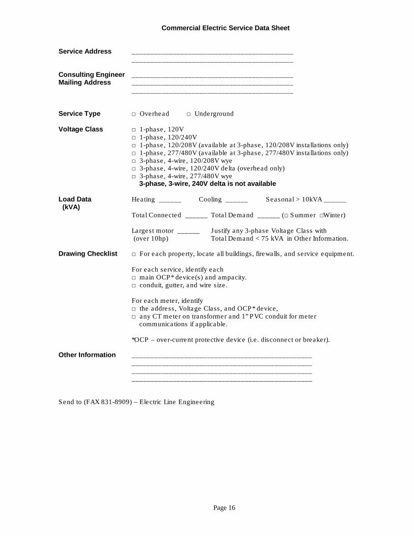
Commercial and industrial projects within the City of Springfield must be submitted via the city’s E-Plan submittal process and ProjectDox electronic plan review program. City Utilities will review all plans submitted through this process. Projects outside the city limits of Springfield are not yet part of this system, therefore plans for projects outside the city need to be submitted directly to City Utilities Developer Services. Contact Developer Services when beginning the permitting process for commercial & industrial projects for any assistance as needed. Plans submitted to the City or County should also include the information requested on the “Commercial Electric Service Data Sheet” given below. Providing this information will ensure City Utilities engineers have the information needed to effectively respond to your request. Not providing this information may result in the plans being unapproved and requiring re-submittal. Review comments for projects located within the city limits of Springfield will be available through the ProjectDox plan review system. City Utilities engineers will review your project plans and data, and work with you to determine a suitable route for the electric extension as required.
Page 16
Commercial Electric Service Data Sheet
Service Address ___________________________________________ ___________________________________________ Consulting Engineer ___________________________________________ Mailing Address ___________________________________________ ___________________________________________ Service Type □ Overhead □ Underground Voltage Class □ 1-phase, 120V □ 1-phase, 120/240V □ 1-phase, 120/208V (available at 3-phase, 120/208V installations only) □ 1-phase, 277/480V (available at 3-phase, 277/480V installations only) □ 3-phase, 4-wire, 120/208V wye □ 3-phase, 4-wire, 120/240V delta (overhead only) □ 3-phase, 4-wire, 277/480V wye 3-phase, 3-wire, 240V delta is not available Load Data Heating ______ Cooling ______ Seasonal > 10kVA ______ (kVA) Total Connected ______ Total Demand ______ (□ Summer □Winter) Largest motor ______ Justify any 3-phase Voltage Class with (over 10hp) Total Demand < 75 kVA in Other Information. Drawing Checklist □ For each property, locate all buildings, firewalls, and service equipment. For each service, identify each □ main OCP* device(s) and ampacity. □ conduit, gutter, and wire size. For each meter, identify □ the address, Voltage Class, and OCP* device, □ any CT meter on transformer and 1” PVC conduit for meter communications if applicable. *OCP – over-current protective device (i.e. disconnect or breaker). Other Information ________________________________________________ ________________________________________________ ________________________________________________ ________________________________________________ Send to (FAX 831-8909) – Electric Line Engineering

Page 17
SECTION 6 SYSTEM ALTERATION AND CONVERSION
For system alterations or conversions, a permit and inspection is required from the local jurisdiction authorizing the meter installation.
6.1 CONVERSION OF EXISTING SYSTEM
All relocations and/or alterations of existing overhead and underground lines and equipment will be accomplished at the expense of the customer initiating the request on an estimated cost basis. The customer will be required to provide all necessary easements and right-of-way without cost to City Utilities. The request must be submitted allowing ample time for City Utilities to investigate, engineer, schedule, and construct the alterations. All relocation and/or alteration requests should be made to City Utilities Developer Services.
Note: For overhead to underground conversions, City Utilities does not guarantee that other utility facilities, such as telephone equipment or cable television, which may be attached to City Utilities poles, will be placed underground. For further information, these utilities should be contacted individually.
REQUIREMENTS FOR WORK PERFORMED ON TIME-AND-MATERIAL BASIS
The requestor will pay the full amount of the estimate to the City Utilities Developer Services Representatives prior to the scheduling of the work.
6.2 CONVERSION OF SINGLE RESIDENTIAL OVERHEAD SERVICE TO UNDERGROUND
In the event the property owner requests conversion of the service conductor from overhead to underground, the customer must convert his service entrance equipment from overhead to underground and install his service lateral conductor. This conversion must be approved by the appropriate inspection authority for that area.
The customer’s electrician is responsible for placing the conduit, ells, pedestal, and conductor from the customer's service equipment to the pedestal. The property owner will assume all costs incurred in replacing fences, sod, trees, shrubs, other landscaping items, and the repair of damages to, or the remodeling of, building structures. City Utilities will furnish the pedestal, and the conduit and ells required from the pedestal to the pole. The flat rate charge for this conversion shall be in accordance with City Utilities’ Extension Policy.
6.3 LINE EXTENSION REQUIREMENTS
Extension of distribution or transmission facilities to a point of delivery to the customer will be made subject to the current City Utilities extension policy. Contact Developer Services for line extension information.
6.4 SINGLE PHASE TO THREE PHASE CONVERSIONS
City Utilities will rebuild its single-phase facilities to accommodate a three-phase service request under the following conditions:
♦ Revenue generated from the addition of the three-phase load will justify the cost of
rebuilding the facilities to three-phase per the current City Utilities extension policy. ♦ Persons who request three phase service pay the cost of rebuilding the facilities to three-
phase. ♦ A combination of the above two conditions.
Page 18
SECTION 7 METERING
7.1 METER INSTALLATION AND OWNERSHIP
All meters, overhead service drops, and other electrical facilities installed by City Utilities at the expense of City Utilities at a customer's premise for the purpose of delivering or measuring energy to the customer, will continue to be the property of City Utilities.
The customer will provide and maintain without cost to City Utilities sufficient and proper facilities for the installation of meters and other apparatus at a readily accessible location.
7.2 METER LOCATIONS AND CLEARANCES
The locations of meters and metering equipment will be designated by City Utilities where they will be readily accessible at all reasonable hours for reading, testing, inspecting, and other maintenance purposes. All meter locations shall be outside unless prior approval is obtained from City Utilities. No wiring dependent upon the meter location should be started until the location has been definitely assigned. Contact Electric Line Engineering prior to performing any work on an existing service or installing any new service. Following are general guidelines applicable to all meter installations. Refer to the appropriate Service Standard for more information.
1. Meter sockets will be plumb and securely fastened to the outside building wall. 2. Meter sockets will be installed five to seven feet above finished grade or permanent
platform. 3. Meter sockets shall not be installed under projections lower than six feet. 4. A minimum of five feet of clear space must be left in front of meter. 5. Electric meters will be located at least five feet horizontally from gas meters. 6. All above ground conduit on the line side of the meter will be galvanized rigid steel
except as noted in specific standards; in all cases the conduit shall meet the requirements of the appropriate inspection authority and the NEC.
OUTDOOR METER LOCATIONS
Outdoor meters will not be installed where they will interfere with traffic, sidewalks, driveways, or where they will obstruct the opening of doors or windows, or in any location which may be considered hazardous or cause damage to the metering equipment.
MULTIPLE OUTDOOR METERS
Where service is supplied to individual customers located in a structure designed for multiple occupancy, the individual outdoor meters will be grouped at a point near the service entrance and must be as specified by the appropriate inspection authority, the NEC, and the appropriate City Utilities Service Standard.
7.3 CURRENT TRANSFORMER METERING
Current transformers (CTs) are required if load (main disconnect size) exceeds 400A, for all voltage classifications except for single phase 120/208V. For single phase 120/208V, CTs are required for any service exceeding 200A. Although 400A, self-contained metering is available for most voltage classifications, City Utilities strongly recommends the use of CT metering for any service exceeding 200A, if there is a chance that the service will need to be upgraded at some point in the future.
CT and meter socket locations must be approved by the Electric Metering Department prior to installation. If the CTs are to be located a distance greater than 40 feet from the meter socket or if the CTs are to be located in an enclosure other than a dedicated CT cabinet, the
Page 19
location must be approved by the Electric Metering Department. CTs are furnished by the Electric Metering Department and may be picked up at 825 N. Belcrest. CTs are installed into the enclosure by the customer.
City Utilities may allow CT metering to be installed at a City Utilities distribution transformer. In these cases, a CT cabinet is not required, but an approved meter socket must still be provided by the customer to be installed by City Utilities on the transformer. Single phase CT metering in distribution transformers requires that the customer furnish and install an approved meter pedestal and conduit from the meter to the pedestal.
Where CT cabinets are required, they will be furnished and installed at the approved location by the customer. All cabinets shall be raintight and shall be equipped with a suitable latch that will be exclusively locked and sealed by City Utilities; all raceways and compartments ahead of the metering will also be exclusively locked and sealed by City Utilities. CT cabinet dimensions will be as specified in the appropriate City Utilities Standard. Preferably, CT cabinets will be installed immediately adjacent to the associated meter socket; however, installations are generally accepted if the meter socket is within 40 feet of the CT cabinet. Distances longer than 40 feet may be approved by the Electric Metering Section.
If CTs are required for a service, the customer shall furnish and install a conduit no less than 1 inch in diameter between the meter socket and the CT location for the exclusive use of City Utilities. This conduit is not necessary when the CT’s are installed by City Utilities in a three-phase distribution transformer. The maximum total length of this conduit shall be no greater than 40 feet, with no more than three 90-degree bends in a single pull section, unless approved by the Electric Metering Department. No LB type elbows or elbows with removable covers shall be allowed. The Electric Metering Department will install and terminate conductors from the CT secondary to the meter socket using the customer-furnished conduit.
7.4 METER SOCKETS
All meter sockets used on secondary voltage classifications are to be furnished and mounted by the customer. These sockets shall be manufactured in accordance with the latest revision of ANSI C12.7, ANSI / UL 50, ANSI / UL 414, and NEMA 250, as well as all other applicable codes and standards, including the latest revision of the NEC.
GENERAL REQUIREMENTS FOR METER SOCKETS
Meter sockets will be constructed of 16-gauge or heavier galvanized sheet steel, and finished with a neutral gray baked-on enamel or similar coating. All socket enclosures will be suitable for outdoor installation (raintight).
The cover shall be of the same material and finish as the enclosure. Ring-type and ringless-type covers are acceptable. Ringless covers will be designed for sealing with a padlock type seal and removable without removing any screws or bolts. All covers will be designed such that removal of any secured portion is not possible without first removing a padlock seal.
Combination meter socket pedestals with service disconnect equipment are acceptable only if they meet other requirements of this document and also maintain separation between line and load access such that all line side access is exclusively locked and sealed by City Utilities. SOCKET JAWS AND TERMINALS
All jaws and terminals shall be securely and permanently mounted to the socket and shall not be removable without removing bolts or screws; plug in terminals in sockets are never acceptable. All jaws, terminals, and buss ducts shall be rated 600V.

Page 20
Meter sockets for apartments and residential complexes shall have jaws and terminals rated for no less than 100A. Meter sockets for commercial installations shall be rated no less than 200A.
METER SOCKET BONDING
Since all service equipment may experience high currents in the event of a ground fault, it is imperative that meter sockets and conduits be effectively bonded to neutral and ground. Effective bonding is to be achieved through the use of threaded fittings in a rigid metal conduit system where the joints are to be made wrench tight. Locknuts and bushings do not fulfill the effective bonding requirement. All bonding apparatus shall meet the requirements of the appropriate inspection authority.
The NEC requires common bonding of all utilities, including cable television, telephone, and electrical systems. It is the customer’s responsibility to provide adequate access to the electric system grounding electrode or grounding electrode conductor such that this requirement can be satisfied by the various utilities.
METER SOCKET WIRING
Customers will wire all self-contained meter installations in accordance with the appropriate City Utilities Service Standard. Wiring of all transformer rated meters will be performed by the Electric Metering Department.
7.5 MOVING OR REMOVING METERS AND METERING EQUIPMENT
The customer shall not tamper or otherwise interfere with the proper operation of City Utilities meters or other equipment, nor in any way interfere with the proper registration of the used electric energy. Only authorized City Utilities employees are permitted to connect, disconnect, move, or remove meters or service drops.
7.6 DEMAND MANAGEMENT SUPPORT AND PULSE INITIATORS
City Utilities shall provide pulse initiator outputs at a convenient junction location to be determined by City Utilities near the location of the electric meter. Pulse initiators are provided free of charge, however, the customer is responsible for all wiring downstream of the junction location determined by City Utilities.
Customers desiring to use this service should contact the Electric Metering Department with their request. The customer should provide all technical requirements of their intended demand monitoring/management system. The Electric Metering Section will determine the appropriate output parameters and execute the required wiring to the junction location.
7.7 MARKING OF MULTIPLE METER SOCKETS
The electrical contractor who installs the wiring shall plainly mark each meter of a multiple meter installation and all individual meter pedestals with a permanently attached metal or hard plastic tag showing which apartment, office, or unit is metered by each meter. The letters or numbers shall be of the permanent stenciled type and must be at least 3/8 inches in height.
Meters will not be installed until all sockets are tagged correctly. In the event that internal numbering or lettering schemes are changed or incorrect tagging creates inaccurate information in the City Utilities records, the owner of the premises will be responsible for all expenses incurred in correcting the situation.
Page 21
SECTION 8 ELECTRIC PERMITS
8.1 ELECTRIC PERMITS
An electric permit is required before performing any type of electric work inside the Springfield city limits or outside the Springfield city limits in Greene County. Permits may be issued only to licensed and bonded electrical contractors.
Permits within the Springfield city limits are obtained by contacting:
Department of Building Development Services 840 N Boonville Springfield, MO 65802 Phone: 417-864-1055
Permits within the Battlefield city limits are obtained by contacting:
City of Battlefield 5434 S. Tower Drive Battlefield, MO 65619 Phone: 417-883-5840
Permits within Greene County, outside the city limits, are obtained by contacting:
Greene County Building Regulations 940 N Boonville, Room 305 Springfield, MO 65802 Phone: 417-868-4015
Permits within Republic city limits, are obtained by contacting:
City of Republic Planning and Development Department 225 N. Main St Republic, MO 65738 Phone: 417-732-3150
It is the customer’s or contractor’s responsibility to obtain the permit from the appropriate inspection authority, complete all work, and notify the inspector when the work has been completed and is ready for an inspection.

Page 22
SECTION 9 CONSTRUCTION TEMPORARY SERVICES
9.1 APPLICATION FOR SERVICE
Temporary service requests are initiated by contacting City Utilities Developer Services.
Developer Services will complete the application, prepare a work order for the Electric Line Operations Department, and collect the appropriate deposits or fees.
The fee charged by City Utilities for a temporary service provides for connecting the temporary at the beginning of a project and disconnecting it upon completion of the project. Additional fees will be charged if the customer requests the temporary to be disconnected and then reconnected at a different location.
On large projects where more than one temporary service is needed, the customer shall pay a temporary fee for each temporary connection.
If line construction is required before a temporary can be connected, the application will be routed to a City Utilities engineer who will prepare construction drawings, and determine the additional cost for City Utilities to do the required work.
9.2 TYPES AND INSPECTION OF TEMPORARY SERVICES
Temporary services at City Utilities are classified by type. TYPE 1 is the most common temporary service constructed to meet City Utilities Standard SO-TEMP or SU-TEMP. This service is normally used to provide residential and small commercial temporary construction power. It is limited to a maximum of 100 amps and to not more than 6 breakers in the breaker box.
City Utilities checks each TYPE 1 temporary service for safety and conformity with the appropriate City Utilities standard. Services with safety concerns (in City Utilities opinion) or not meeting City Utilities standards will not be connected and will be "red tagged."
The red tag will be attached to the service equipment. It will indicate the problem(s) found with the temporary service. Correction of these problems is the customer's responsibility. After the problems have been corrected, please notify City Utilities at one of the numbers shown on the red tag. City Utilities normally re-checks temporary services the next business day. If the customer requires a same day re-check an additional fee will apply. City Utilities will, under normal circumstances, connect your temporary service one to two working days after receiving notification that the problem has been corrected.
TYPE 2 temporary service is used for larger commercial projects where more than a 100 amp service or more than 6 breakers in the breaker box are needed to meet the customer's requirements. These services shall use City Utilities Standards SO-TEMP or SU-TEMP as general guidelines for building the service.
An inspection is required for all TYPE 2 temporary services. Inside the Springfield city limits, the City Electric Inspectors will inspect the service. A permit is required and installation must be performed by a licensed electrical contractor. Outside the Springfield city limit, the Greene County inspectors or other municipal inspection authorities will inspect the service. In Greene County the electrician must obtain a permit before doing any work on the service. It is the customer's responsibility to notify the inspector when the service work is complete and ready for inspection.
Page 23
Temporary service is restricted to a time period not to exceed 6 months.
The customer is required to furnish and install all materials for the temporary service.
The temporary service must be self-supporting; it may not be attached to any City Utilities pole or equipment for support. It must be equipped with ground fault circuit interrupters and will conform in all aspects to the current edition of the NEC and NESC.
TYPE 1 overhead temporary services shall be located at least 10 feet and not more than 80 feet from City Utilities poles and equipment.
Location of TYPE 2 temporary services will be determined by City Utilities on a case-by-case basis.
Underground temporary services shall be located 5-7 feet from City Utilities transformers or secondary service pedestals.
9.3 SCHEDULING OF TEMPORARY SERVICE CONNECTS
Before City Utilities can connect a TYPE 1 standard construction temporary service, a correctly addressed work order for the service must be obtained.
Before City Utilities can connect a TYPE 2 construction temporary service, a correctly addressed meter order for the service and an inspection approval from the appropriate inspection authority must be obtained
The inspector will, under normal circumstances, notify City Utilities of a service approval one to two working days after the inspection.
City Utilities will, under normal circumstances, connect your temporary service one to two working days after receiving notification the service is ready to be connected and receiving an inspection approval if required.
City Utilities will not connect any service in which an obvious unsafe condition exists.
Page 24
SECTION 10 SPECIAL EVENT SERVICES
10.1 APPLICATIONS OF SPECIAL EVENT SERVICES
A special event service would provide service to:
♦ Firework Stands
♦ Food or Drink Stands ♦ Christmas Tree Stands
♦ Carnivals
♦ Portable Greenhouses ♦ Short Term (1 - 2 Day) Events
10.2 TYPES OF SPECIAL EVENT SERVICES
Special event services are divided into two classifications.
Classification 1 Special Event Services are served from a permanent customer meter pole.
City Utilities prefers serving special event services by this method. The service is constructed to meet City Utilities Standards SO-MP 100 or SO-MP 200. For these installations, a main breaker box is required, with sub-breakers to serve the individual customer requirements. All 120-volt receptacles shall be protected by ground fault circuit interrupters.
The meter pole must be permanently tagged with numbers 3 inches high, which show the correct street address.
This type of service requires the inspection of the original installation by the appropriate inspection authority. The service must be installed by a licensed electrical contractor. Once disconnected this service may not be reconnected until after a safety check is performed by City Utilities This service remains on-site for future use.
Classification 2 Special Event Services are served by the customer installing a Type I construction temporary service.
The service is constructed to meet City Utilities Standard SO-TEMP for overhead applications or SU-TEMP for underground applications. When using a Type I temporary service to serve a special-event customer inside the city limits, the service must be installed by a licensed electrical contractor.
The customer is required to pay the normal charge for a temporary service.
An inspection is required each time this type of service is connected.
Special event services are restricted to a continuous time period not to exceed 3 months.
The customer is required to furnish and install all materials for the service.
The service must be self-supporting, and it may not be attached to any City Utilities pole or equipment for support. It must be equipped with ground fault circuit interrupters and conform in all aspects to the current edition of the NEC and NESC.
Overhead services shall be located at least 10 feet and not more than 80 feet from City Utilities poles and equipment.
Page 25
10.3 APPLICATION FOR SPECIAL EVENT SERVICE
Classification 1 special event service requests for existing meter poles are initiated by contacting City Utilities Commercial Accounts.
Classification 1 special event service requests involving new meter pole installations are initiated by contacting City Utilities Developer Services. City Utilities will determine the location of the meter pole.
Classification 2 special event service requests are initiated by contacting City Utilities Developer Services.
Commercial Accounts or Developer Services will complete your application, prepare a work order, and collect the appropriate deposits or fees.
The fee charged by City Utilities for a special event service provides for connecting the service at the beginning of an event and disconnecting it upon completion of the event.
If line construction is required before your service can be connected, your application will be routed to a City Utilities Engineer who will meet with you, discuss your request, prepare construction drawings, and determine if you will be required to pay additional costs for City Utilities to do the required work.
10.4 INSPECTION OF SPECIAL EVENT SERVICES
A special event service must be initially inspected by the appropriate inspection authority before it can be connected by City Utilities.
It is the customer's responsibility to notify the inspector when the service work is complete and ready for inspection.
10.5 SCHEDULING OF SPECIAL EVENT SERVICE CONNECTS
Before City Utilities can connect an electric service, we must have a correctly addressed work order for the service and, when required, an inspection approval from the appropriate inspection authority.
The inspector will, under normal circumstances, notify City Utilities of a service approval one to two working days after the inspection.
City Utilities will, under normal circumstances, connect your service one to two working days after receiving the inspector's approval.

Page 26
SECTION 11 PERMANENT OVERHEAD SERVICES
11.1 APPLICATION FOR SERVICE
Permanent service requests are initiated by contacting City Utilities Developer Services.
Developer Services will complete your application, prepare a work order for the Electric Line Operations Department, and collect the appropriate deposits or fees.
If line construction is required before your service can be connected, your application will be routed to a City Utilities Engineer who will meet with you, discuss your request, prepare construction drawings, and determine if you will be required to pay additional costs for City Utilities to do the required work.
11.2 INSPECTION OF PERMANENT SERVICES
A permanent service must be inspected by the appropriate inspection authority before it can be connected by City Utilities.
It is the customer's responsibility to notify the inspector when the service work is complete and ready for inspection. Reconnects and rewires require an electric permit from the local jurisdiction.
11.3 SCHEDULING OF PERMANENT SERVICE CONNECTS
Before City Utilities can connect an electric service, we must have a correctly addressed work order for the service and an inspection approval from the appropriate inspection authority.
The inspector will, under normal circumstances, notify City Utilities of a service approval one to two working days after the inspection.
City Utilities will, under normal circumstances, connect a new service one to two working days after receiving the inspector's approval.
11.4 OVERHEAD SERVICES
The customer must furnish, install, and maintain the electrical service which consists of a service disconnect device, meter socket, CT enclosure (if required), service entrance conductor, service entrance conduit, weatherhead, point of attachment, and other related items.
City Utilities furnishes and installs the service drop conductor from the City Utilities pole to your service point of attachment, makes the connections at the pole, the service entrance (weatherhead), and sets a meter in the meter socket.
11.5 SERVICE/METER LOCATION
City Utilities reserves the right to determine service and meter locations and service attachment heights.
Refer to the Metering Section of this manual for specific guidelines regarding electric meter locations and installations.
Questions concerning service or meter locations should be directed to the City Utilities Developer Services.
Page 27
11.6 POINT OF ATTACHMENT
The point of attachment (the place where City Utilities service drop conductors attach to the structure or service entrance conduit shall be on the outside of the building where it can be satisfactorily reached from a City Utilities pole.
The point of attachment must be positioned so the service drop conductor will meet all horizontal and vertical clearances required by the NEC and NESC. See City Utilities clearance specification drawings in this booklet. If you have questions about clearance requirements, contact City Utilities Developer Services.
11.7 METHOD OF ATTACHMENT
On residential services the preferred method of attachment is to extend a 2-inch rigid conduit riser between 36 inches and 48 inches above the roof.
On all new or remodeled buildings, the customer shall install an insulated neutral clevis or other dead-end insulating device of adequate strength to support the service drop conductor. On buildings of masonry or fireproof construction, dead-end devices are to be mounted by means of through bolts set in the structure.
Service knobs will not be placed in the roof. A minimum of 2 inches of thread length into a solid framing member (stud) is required to use a service knob. Service knobs with a four-inch thread length are recommended.
On metal buildings, the contractor must provide an attachment point strong enough to support the service drop conductor. The attachment point must be attached to the building frame to provide adequate support.
11.8 SERVICE ATTACHMENT HEIGHTS
The minimum attachment height for a single-phase residential service is 12 feet above finished grade. Refer to City Utilities service standard drawing SO- ATT for more information.
The minimum attachment height for a three phase or commercial service is 15 feet above finished grade. Refer to City Utilities service standard drawing SO- ATT for more information.
If the City Utilities service drop conductor must cross a street or driveway, a higher attachment height may be required. Refer to City Utilities service standard SO – CLEAR for more information.
11.9 LENGTH OF SERVICE DROP
The length of service drop is the distance from the City Utilities pole to the customer’s point of attachment. For most residential services, 80 feet is the maximum length allowed for a service drop.
To meet minimum clearances required by the NEC and NESC, it may be necessary to provide City Utilities with a higher point of attachment. In some cases, the customer may be required to move the service location or point of attachment closer to a City Utilities pole.
Page 28
11.10 SERVICE DROP POLES
A service drop pole may be required when length of the service drop is excessive or proper clearances cannot be maintained, or the size of the service drop conductor would cause excessive mechanical strain upon either the customer's structure or City Utilities pole.
The service drop pole is normally placed on the property being served by the electric service.
When more than one customer is served by a service drop pole, an easement may be required before the pole can be installed.
If a service drop pole is installed to re-route an existing service or to reach a service location other than one approved by City Utilities, the customer will be required to pay the total cost of installing the pole. Requests by customers for City Utilities to install additional poles or equipment should be handled through City Utilities Developer Services.
Page 29
SECTION 12 PERMANENT UNDERGROUND SERVICES
12.1 APPLICATION FOR SERVICE
Permanent service requests are initiated by contacting City Utilities Developer Services.
Developer Services will complete your application, prepare a work order for the Electric Line Operations Department, and collect the appropriate deposits or fees.
If line construction is required before your service can be connected, your application will be routed to a City Utilities Engineer who will meet with you, discuss your request, prepare construction drawings, and determine if you will be required to pay additional costs for City Utilities to do the required work.
12.2 INSPECTION OF PERMANENT SERVICES
A permanent service must be inspected by the appropriate inspection authority, before it can be connected by City Utilities.
It is the customer's responsibility to notify the inspector when the service work is complete and ready for inspection. Reconnects and rewires require an electric permit from the local jurisdiction.
12.3 SCHEDULING OF PERMANENT SERVICE CONNECTS
Before City Utilities can connect an electric service, we must have a correctly addressed work order for the service and an inspection approval from the appropriate inspection authority.
The inspector will, under normal circumstances, notify City Utilities of a service approval one to two working days after the inspection.
City Utilities will, under normal circumstances, connect a new service one to two working days after receiving the inspector’s approval.
12.4 UNDERGROUND SERVICES
The customer is required to furnish, install and maintain all service equipment. This consists of a service disconnect device, meter base, CT enclosure (if required), service protection conduit, service lateral conduit, service lateral conductor, and other related items.
City Utilities reserves the right to determine meter locations. Refer to the Metering Section of this manual for specific guidelines regarding electric meter locations and installations. Questions concerning service or meter locations should be directed to the City Utilities Developer Services. City Utilities maintains a no-dig zone within three feet of any City Utilities transformer, pedestal, or other underground electrical equipment. Excavations required within this area will be performed by City Utilities.
City Utilities provides 2 inch conduit stub-outs at all residential transformer and secondary service pedestal locations. The customer shall connect the service lateral conduit to this stub-out. If the stub-out cannot be located, or if additional stub-outs are needed, call City Utilities Developer Services for assistance.

Page 30
When the service lateral conductors are ready to be installed, the customer or customer designated contractor shall notify City Utilities Field Schedulers one working day in advance to unlock the transformer or secondary service pedestal.
Customers are granted access into City Utilities equipment for the purpose of installing service lateral conductors into their conduit. During this period, the customer or customer-designated contractor is responsible for maintaining the safety of the equipment and personnel working in or near the energized equipment, and in no case shall the transformer or pedestal be left open and unattended. Electrical contractors needing to work inside City Utilities transformers and pedestals will be required to sign a release form that indicates their compliance with safety and security policies applicable to energized electrical equipment. Each opened device will be inspected by a City Utilities supervisor, technician, or troubleshooter immediately after the end of the business day that it was opened. Equipment that is found unsecured will be reported, and the responsible party will be contacted for follow-up.
When the customer installs the service lateral conductors, a minimum of 3 feet of conductor length above the base of the transformer pad or a minimum of 2 feet above the top of the secondary service pedestal shall be installed to ensure sufficient cable is available for City Utilities to make connections.
City Utilities will provide all connectors and make all connections in City Utilities transformers and secondary service pedestals.
12.5 UNDERGROUND SERVICE IN AREAS SERVED BY UNDERGROUND ELECTRIC LINES
In residential subdivisions, City Utilities transformer or secondary service pedestal is typically installed on the street side of each lot.
When an existing transformer or secondary service pedestal is present on your property, the underground service must be extended to it by the customer. Contact City Utilities Developer Services to determine which source to use for service.
12.6 UNDERGROUND SERVICE IN AREAS SERVED BY OVERHEAD ELECTRIC LINES
In areas served by City Utilities overhead electric lines, there are three options by which a customer may receive a new underground electric service.
The first option is for the customer to install a customer meter pole, per City Utilities service standard SO-MP 100 or SO-MP 200. The customer is required to furnish and install the pole and all service equipment. City Utilities will install an overhead service drop to the customer's meter pole, make the connections at the customer's weatherhead, and set a meter. There are no construction charges from City Utilities for this option.
The second option is for the customer to request City Utilities to install a secondary service pedestal next to an existing City Utilities pole. After City Utilities installs the pedestal, the customer installs the underground service as outlined in this section. There are no construction charges from City Utilities for this option.
The third option is for the customer to pay City Utilities to install an underground electric primary line and padmounted transformer. If the customer chooses this option, a City Utilities Engineer will determine the cost and feasibility of the installation. After City Utilities completes its work, the customer would install the underground service as outlined in this section.
Page 31
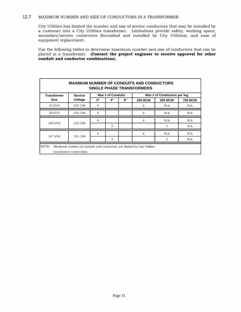
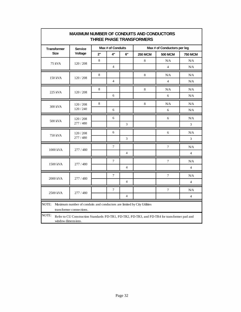
12.7 MAXIMUM NUMBER AND SIZE OF CONDUCTORS IN A TRANSFORMER
City Utilities has limited the number and size of service conductors that may be installed by a customer into a City Utilities transformer. Limitations provide safety, working space, secondary/service connectors (furnished and installed by City Utilities), and ease of equipment replacement.
Use the following tables to determine maximum number and size of conductors that can be placed in a transformer. (Contact the project engineer to receive approval for other conduit and conductor combinations).
250 MCM 500 MCM 750 MCM
6 N/A N/A
6 N/A N/A
6 N/A N/A
3 N/A
6 N/A N/A
3 N/A
NOTE:
MAXIMUM NUMBER OF CONDUITS AND CONDUCTORS
SINGLE PHASE TRANSFORMERS
120 /240
120 /240
3120 /240
Max # of Conductors per leg
3
6
6
6
6
25 kVA
50 kVA
120 /240
Transformer
Size
Max # of Conduits
2" 4" 6"
Service
Voltage
Maximum number of conduits and connectors are limited by City Utilities
transformer connections.
100 kVA
167 kVA
Page 32
250 MCM 500 MCM 750 MCM
8 N/A N/A
4 N/A
8 N/A N/A
4 N/A
8 N/A N/A
6 N/A
8 N/A N/A
6 N/A
6 N/A
3
6 N/A
3
7 N/A
4
7 N/A
4
7 N/A
4
7 N/A
4
NOTE:
NOTE:
Max # of Conductors per leg
4"
4
Transformer
Size
8
120 / 208
4
4
3
7
7
120 / 208
120 / 208
120 / 240
4
6
6
6
7
1500 kVA
277 / 4807
277 / 480
MAXIMUM NUMBER OF CONDUITS AND CONDUCTORS
THREE PHASE TRANSFORMERS
120 / 208
3
8
8
transformer connections.
4
277 / 480
750 kVA
500 kVA
1000 kVA
277 / 480
120 / 208
277 / 480
4
120 / 208
277 / 480
75 kVA
150 kVA
8
Max # of Conduits
2" 6"
Refer to CU Construction Standards PD-TR1, PD-TR2, PD-TR3, and PD-TR4 for transformer pad and
window dimensions.
2000 kVA
2500 kVA
Service
Voltage
6
Maximum number of conduits and conductors are limited by City Utilities
225 kVA
300 kVA
Page 33
SECTION 13 REWIRING OF EXISTING SERVICES
13.1 SERVICE REWIRES
When a customer decides to increase the capacity of his existing electric service, or upgrades from 120 volts to 120/240 volts, it will be considered a service rewire. All rewires must result in a meter location on the outside of the structure at a location approved by City Utilities. This work requires a permit which is issued by the appropriate inspection authority.
When a customer replaces a fuse box with a breaker box, moves a service from one location on a building to another location on the same building, or moves an electric meter from an inside to an outside location, the customer must contact the appropriate inspection authority to determine the type of permit required and the amount of work that must be completed.
Inside the Springfield city limits, all service upgrades which consist of increasing the capacity of a main fuse or breaker box, meter base, and service entrance or service lateral conductor, must be performed by a licensed and bonded electrician.
On all rewire projects, the property owner or electrical contractor should contact City Utilities Developer Services, to determine an acceptable meter and service attachment height and location.
After the rewire has been reconnected by City Utilities, removal of the old service equipment is the responsibility of the owner or contractor.
On delta-connected three phase rewire projects where the service is upgraded or converted to a combination 4 wire service, the electrician is responsible for maintaining proper phase rotation and proper use of the higher voltage (wild-leg) conductor. See SO-GN6 or SU-GN4 for special tagging requirements for this service.
13.2 INSPECTION OF SERVICE REWIRES
Rewired services must be inspected by the appropriate inspection authority before being reconnected by City Utilities.
It is the customer's responsibility to notify the inspector when the service work is complete and ready for inspection.
If, at the customer's request, City Utilities disconnects an electric service for a rewire project, we cannot reconnect the service without approval of the electric inspector.
13.3 SCHEDULING OF SERVICE REWIRE RECONNECTS
Before City Utilities can connect a rewired electric service, we must have an inspection approval from the appropriate inspection authority.
The inspector will, under normal circumstances, notify City Utilities of a service approval one to two working days after the inspection.
City Utilities will, under normal circumstances, connect the service one to two working days after receiving the Inspectors' approval.
When a customer asks for a service reconnect to occur outside City Utilities normal working hours, the customer will be required to pay all additional overtime costs.

Page 34
While performing a rewire project, it may become necessary to remove or bypass the electric meter. This condition may be allowed in some circumstances, but only with prior approval from City Utilities Electric Metering Department.

Page 35
SECTION 14 MULTIPLE SERVICE RESTRICTIONS
14.1 NUMBER OF SERVICES ON A BUILDING
This section is intended for use when a customer requests more than one electric service to be installed on a single building. On City Utilities’ system, only one overhead service drop or underground service lateral or service location will be allowed on a building, except for exceptions as defined herein.
Services of different classifications, such as a single phase and three phase overhead service, served by a single drop, are considered as one service.
14.2 APPLICATION FOR SERVICE
City Utilities usually becomes aware of service requests through the city or county plan review process or from a specific customer request. City Utilities reviews the plans for availability of electric service and general service configuration. City Utilities’ plan review comments are provided through ProjectDox for all projects within the city limits of Springfield. Plans for projects outside the city limits will be reviewed by City Utilities engineers/designers who will work directly with the customer’s architect and/or engineer making the request for the project.
Prior to beginning site work on a project, the contractor or his representative should contact City Utilities Developer Services to make a formal request for permanent and temporary electric service. The applicant should bring building permit information and correct address.
14.3 DEFINITION OF A BUILDING, FIRE WALL AND FIRE SEPARATION WALL
A building is a structure that stands alone or that is cut off from adjoining structures by "fire walls" with openings therein protected by approved fire doors. See NEC Article 100.
The inspection authority having jurisdiction shall determine the definition of and acceptability of "fire walls" and "fire separation walls."
A "fire separation wall" does not meet requirements for a separate service location.
14.4 GUIDELINES FOR MULTIPLE SERVICE LOCATIONS
To receive approval for multiple service locations on a single building, the following guidelines shall apply.
1. Meet requirements of the NEC and all applicable local codes and standards. 2. Request and be granted an allowable "exception" to the NEC or NESC. 3. Meet requirements of city or county inspection authority having jurisdiction. 4. Meet City Utilities’ requirements. 5. Maintain a 10 foot maximum distance between service locations. 6. Each service shall be visible from the other. 7. All services must be permanently tagged to indicate other service locations.
14.5 APPROVAL FOR MULTIPLE SERVICES ON A BUILDING
If a customer has a project where more than one electric service on a building is being planned, they must receive pre-approval before beginning any work.
Page 36
SECTION 15 ADDITIONAL SERVICE REQUESTS
15.1 ADDITIONAL SERVICE REQUESTS
An additional service request on property already served by City Utilities may require customer payment for the additional service as outlined below. The typical request involves adding a new service to serve an unattached garage, barn, structure or other facility such as a well or sign that requires electric service.
If City Utilities determines an additional service request cannot be adequately served from City Utilities’ existing facilities and an electric upgrade is required for increased capacity due to the projected load addition, Electric Line Engineering shall determine if any customer costs are required based on the Extension Policy. If City Utilities determines an additional service request can be adequately served from City Utilities’ existing facilities and the projected load addition can be served from the customer’s existing service location (with or without modification to the customer’s primary or secondary metered electric facilities and/or service equipment), any requested City Utilities line construction needed to facilitate the additional service request (other than a service drop from existing City Utilities’ facilities)will be at the customer’s expense.
The actual location and configuration of the additional service will be determined jointly by the customer, the appropriate inspection authority and a City Utilities Engineer.
15.2 BUILDING REGULATIONS APPROVAL
The first step in obtaining approval for a second electric service is to contact the appropriate inspection authority for that area.
Each second service request is handled on a case-by-case basis.
City Utilities’ plan review comments are provided through ProjectDox for all projects within the city limits of Springfield. Plans for projects outside the city limits will be reviewed by City Utilities engineers/designers who will work directly with the customer’s architect and/or engineer making the request for the project.
15.3 CITY UTILITIES APPROVAL AND COST
Once the request is approved by the city or county inspector, the customer must contact City Utilities Developer Services. The service application is completed by Developer Services and routed to a City Utilities engineer.
A City Utilities engineer will meet with you, discuss your request, and determine the cost to you for City Utilities to do the work.
15.4 PERMITS AND SERVICE CONSTRUCTION
Prior to doing any work on a new electric service, permits must be obtained from the appropriate inspection authority.
The customer must furnish and install all materials for the service. For additional service construction information see the appropriate sections of this booklet.
Page 37
15.5 INSPECTION OF PERMANENT SERVICES
All permanent services must be inspected by the appropriate inspection authority before they can be connected by City Utilities.
It is the customer's responsibility to notify the inspector when the service work is complete and ready for inspection.
15.6 SCHEDULING OF PERMANENT SERVICE CONNECTS
Before City Utilities can connect an electric service, we must have a correctly addressed meter order for the service and an inspection approval from the appropriate inspection authority.
The inspector will, under normal circumstances, notify City Utilities of a service approval one to two working days after the inspection.
City Utilities will, under normal circumstances, connect a new service one to two working days after receiving the inspector's approval.

Page 38
SECTION 16 MULTIPLE METER INSTALLATIONS
16.1 MULTIPLE METER INSTALLATIONS
This section is intended to be used for commercial, strip centers, apartments, and other projects where more than two meters are needed from a single service location.
16.2 APPLICATION FOR SERVICE
City Utilities usually becomes aware of a multiple meter project through the city or county plan review process or through customer requests. City Utilities reviews the plans for availability of electric service and general service configuration. City Utilities preliminary plan review comments are given to the Springfield Department of Building Development Services, the Greene County Building Regulations office or the specific customer making the request.
Prior to beginning site work on a project, the contractor or his representative should contact City Utilities Developer Services to make a formal request for permanent and temporary electric service. The applicant should bring building permit and correct address information for City Utilities use.
16.3 PRE-APPROVAL OF SERVICE EQUIPMENT
The final service equipment configuration must be pre-approved prior to ordering any service equipment for the project.
After the service information has been reviewed and approved, a copy of this information will be given to City Utilities Developer Services office. They will generate a work order for each meter and forward it to the Electric Line Operations Department and the Electric Metering Department.
16.4 METER BASE TAGGING
Prior to calling for an inspection, each meter base or main disconnect device shall be tagged to indicate the specific address, unit or apartment number that the meter serves.
Metal or hard plastic address tags may be used and must be permanently attached to the meter base or main disconnect device. See section 7.7 for the requirements on marking multiple meter bases.
The address may also be stamped into the meter base or main disconnect device cover.
16.5 INSPECTION OF SERVICES
All permanent services must be inspected by the appropriate inspection authority before they can be connected by City Utilities.
It is the customer's responsibility to notify the inspector when the service work is complete and ready for inspection.
16.6 SCHEDULING OF SERVICE CONNECTS
Before City Utilities can connect an electric service, we must have a correctly addressed work order for the service and an inspection approval from the appropriate inspection authority for each new meter being connected.
Page 39
The inspector will, under normal circumstances, notify City Utilities of a service approval one to two working days after the inspection.
City Utilities will, under normal circumstances, connect your new service one to two working days after receiving the inspector's approval.
A City Utilities service crew will connect the service and energize it to the main service disconnect.
To help ensure proper meter tagging, the electrician must contact City Utilities Electric Metering Department to coordinate the setting of electric meters and to check each meter to be sure it feeds the proper address.
Page 40
SECTION 17 MULTIPLE DWELLING UNITS
17.1 MULTIPLE DWELLING UNITS
This section is intended to clarify when meters for multiple dwelling units such as condominiums, duplexes, patio homes, townhouses, tri-plexes or four-plexes may be placed on each individual unit, or when the meters must all be placed at a common location.
17.2 UNITS SEPARATED BY FIRE WALLS
When units are separated by a "fire wall" as determined by the appropriate inspection authority, an electric meter may be placed on each individual unit.
17.3 UNITS NOT SEPARATED BY FIRE WALLS
When units are separated by common building walls, fire separation walls, or other construction not meeting "fire wall" requirements as determined by the appropriate inspection authority, electric meters for all units must be grouped at a common location.
A fire separation wall does not meet requirements as a "fire wall."
Page 41
SECTION 18 MOBILE HOME PARKS
18.1 MOBILE HOME PARK MASTER METER CONVERSION
In the event that an existing mobile home park, which is master metered, wishes City Utilities to take over the electric system and individually meter each mobile home, the following procedure applies.
The Mobile home park owner contacts Electric Line Engineering concerning the request. Electric Line Engineering determines the value of the mobile home park primary and secondary electric facilities in their current condition. This does not include service equipment. Engineering also determines any associated cost of reconfiguring the electric system to meet City Utilities and NESC standards. Engineering determines a fair value for City Utilities to pay for the electric facilities. The fair value of the facilities shall never be less than zero. The fair value determination shall also include the cost to City Utilities to dispose of PCB and PCB contaminated transformers in the park's electric system. Electric Line Engineering informs the mobile home park owner of the fair value of the facilities and the tree trimming required. All tree trimming required by City Utilities shall be performed at the mobile home park owner’s expense prior to the execution of a sale agreement. If the mobile home park owner agrees that the value of the facilities as determined by Electric Line Engineering is fair, City Utilities will prepare the necessary documents for the sale of the facilities including permanent easements for all electric facilities to be transferred. The width, length, and locations of the easements will be determined by engineering. After the mobile home park owner has approved and signed the sale documents and easements, the appropriate documents will be signed by City Utilities’ General Manager and will be submitted to the Board of Public Utilities for approval. If the Board approves the agreement, the easements will be recorded and the sale and transfer of facilities shall be complete. If the Board rejects the sale of the facilities, then the transaction shall be null, void, and of no force or effect. The easements will be returned to the mobile home park owner. Note: Electric Line Engineering has no authority to enter into any contract without approval from the Board of Public Utilities.