INTRODUCTION - Austin, Texas
23
Transcript of INTRODUCTION - Austin, Texas
Austin-Bergstrom International Airport Master Plan Update
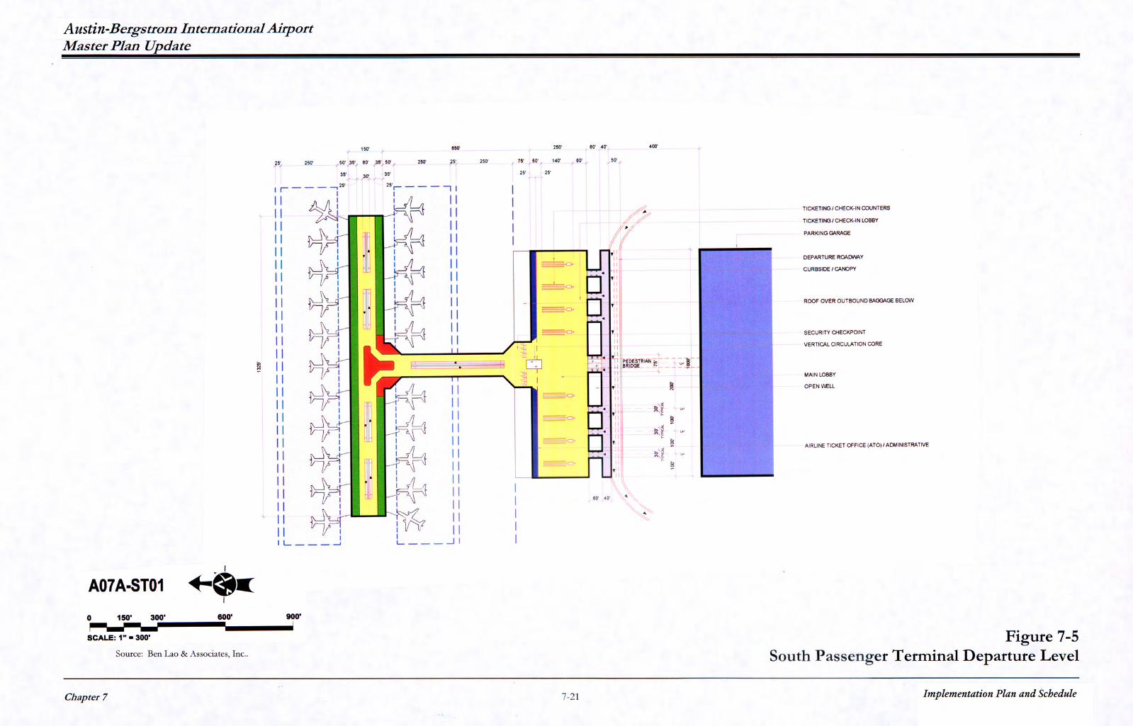
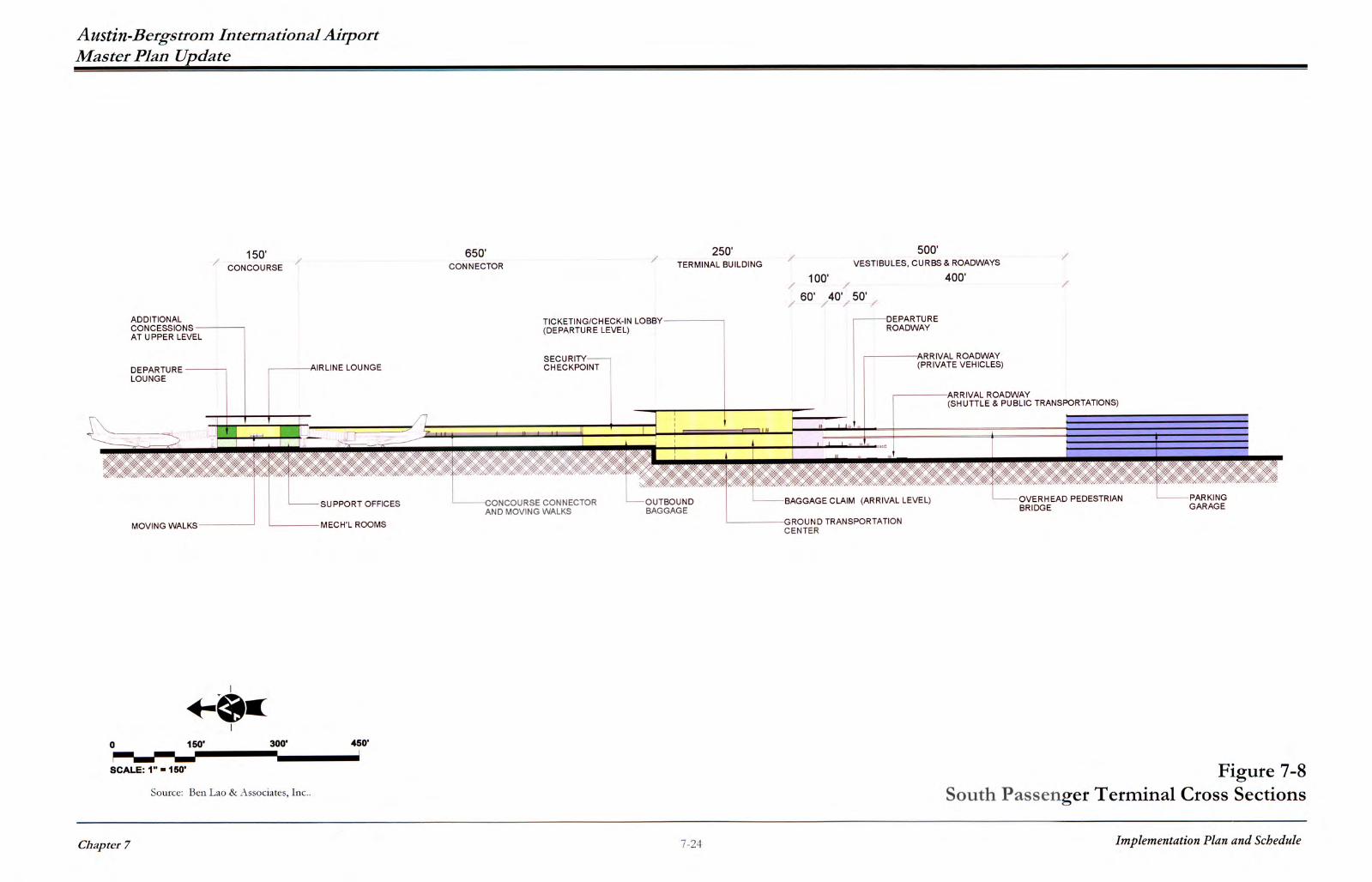
It is recommended that the ticketing/check-in counters in the South Terminal be configured in an "Island Counter" arrangement for a more effective check-in process as well as a more effective security screening procedure for all checked baggage. It should be noted that the island counter configuration, while not common in most U.S. domestic operations, is a design most prevalent in international operation in international terminals overseas as well as a few common–use international facilities in the United States such as at LAX, SFO, and the new International Arrivals Building and Terminal One at JFK. The main terminal building is accessible from the curbside through entry vestibules approximately 30 feet by 60 feet spaced 100 feet apart centerline to centerline. Beyond the idea of containing conditioned air from escaping during the openings and closures of the entry doors by increasing the depth and distance between the two sets of entry doors within the vestibules, the extended depth of the entry vestibule is intended to accommodate longer than usual queuing conditions should it be necessary or should it occur under certain security screening requirement. In between the vestibules are openings intended to serve as ventilation openings for the lower level roadways to prevent vehicular exhaust fumes from accumulating on the lower level roadways and curbsides. Some of the areas in between the vestibules may also be designed to accommodate restroom facilities, telephone booths, as well as minimal concession facilities to provide food and beverage service and news and confectionaries stands. The curbs and roadway elements are described in the following subsection. However, if required prior to or at the start of design, the curbside depth may be further expanded which will affect the placement of the roadways. In addition to the vestibules, the intended separation of curb to the face of the main terminal is recommended at 100 feet. The recommended distance between the face of the south terminal and the new parking structure is 500 feet, far above the minimum separation distance mandated by the Federal Government between terminals and parking structures for security purposes. Access to and from the parking garage and the terminal building is via an enclosed air-conditioned pedestrian bridge equipped with a set of moving sidewalks. The pedestrian bridge is located between the ticketing/check-in level and the baggage claim level. While only one single pedestrian access is shown centrally positioned between the garage structure and the terminal building for more effective security control measures, additional pedestrian bridges similarly equipped with moving sidewalks should be considered at the time of design and/or prior to construction along the eastern and western edges of the terminal. The purpose is to enhance passenger convenience should future analysis prove such additional access points are necessary and when they will not diminish security controls in place or those that may be required at the particular planning level. For the departing passengers, access to the secured side of the airport is controlled by a centralized security checkpoint planned to accommodate a number of passenger screening and carry-on baggage x-ray devices. The security checkpoint is 200 feet wide and may be expanded on an east–west alignment if required in the future to support passenger activities beyond Planning Level 3. The entire terminal space in front of the security checkpoint is maintained and should be maintained as an unobstructed free zone to accommodate heavy queuing conditions should it occur as well as allow
Chapter 7
7-25
Implementation Plan and Schedule
Austin-Bergstrom International Airport Master Plan Update
flexibility for the Department of Aviation to relocate the security checkpoint farther up front if necessary. The space located immediately after the security checkpoint tapers toward a 100 foot wide passenger connector equipped with moving sidewalks. The space for the moving walks should be such that a pair of the super wide moving sidewalks, one each for the departure and arrival traffic, can be installed, or four units of the regular 36 inch wide moving walks can be accommodated side by side, two of which shall be oriented for the departing passengers, and the other two oriented for the arriving passengers. The total passenger connector length including the areas assigned for the security checkpoint and the access area to the baggage claim level of the terminal shall be 650 feet. The distance between the terminal and the concourse hence establishing the length of the connector, is determined by the depth of the apron area allocated for each aircraft parking position on the south side of the concourse and the aircraft taxilane clearance requirement behind it. The recommended distance between the south face of the concourse and the north face of the terminal structure on the upper level is 650 feet. On the apron level, it is reduced to 575 feet because of the single story extension of the outbound baggage area that protrudes 75 feet beyond the north face of the terminal on the ticketing level. This distance and clearance is arrived at by adding the parking depth of 300 feet assigned for each aircraft gate on the concourse, adopted for use on both the south side and the north side, a 25 feet service right-of-way immediately behind the aircraft parking depth allocated, and the taxilane dimensions based on Group IV aircraft type. While not essential, the connector tapers wider toward the concourse at a 45-degree angle to open up the entry way into the concourse. The areas are intended to primarily accommodate concession facilities. The concourse as shown is recommended to be 150 feet in depth and 1,325 feet in length to accommodate a total of 21 gates in addition to the 31 to 32 gates already in full use at the existing north terminal. While the depth is substantially wider than most airport concourses in existence, it is anticipated that the width is necessary to accommodate the larger influx of people in the concourses should a low cost carrier or carriers increase its flight frequencies as well as expand its operations beyond presently known destinations being served. It is also anticipated, based on the master plan concepts generated, that the concourse is to be further expanded east and west to accommodate future gate requirements. The quick turn-around time required by the low-cost carrier or carriers and the increased dwell time of passengers will require more passenger holding and relaxation areas including more concessions particularly in the food and beverage arena, rest room facilities and other amenities and services that may come to light at the time of the initiation of the building program. None of these specifics are shown as these are elements of design that should be carefully programmed at the start of implementation. The concourse width has holdroom spaces arranged along all perimeter walls on both the north and south side of the concourse. The depth of these holdroom areas are recommended at 35 feet. The center portion of the concourse shall be dedicated for the placement of moving sidewalks running in the east and west direction. It is recommended that space be allocated for three wide-size moving
Chapter 7
7-26
Implementation Plan and Schedule
Austin-Bergstrom International Airport Master Plan Update
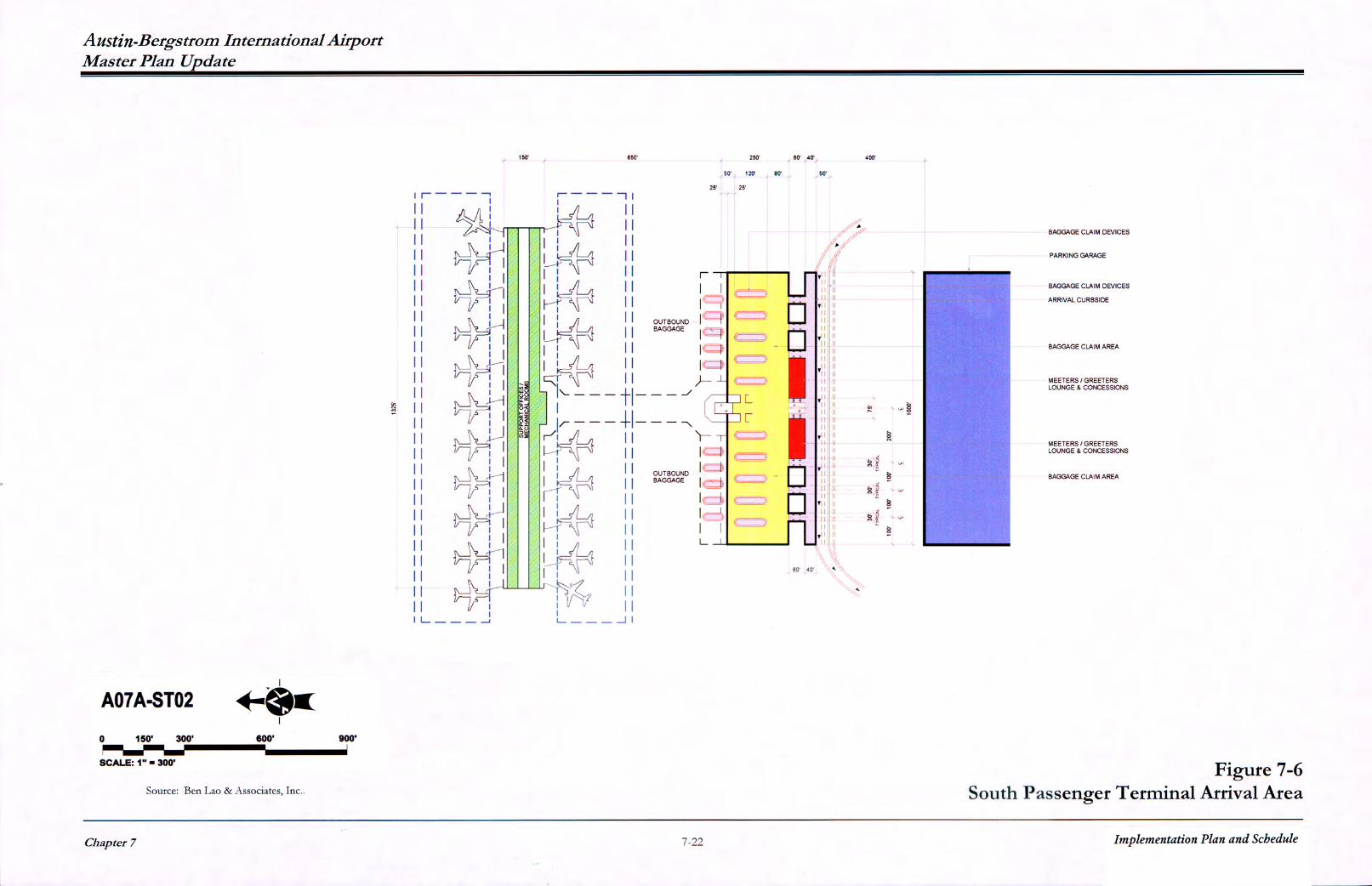
walks in the middle, with one to serve as a back-up and interchangeable in direction. The actual length of each set of the moving walks shall be determined at the time of design based upon actual needs and distribution of the functional areas within the concourse. Concession facilities, restrooms, including mechanical and utility rooms, chase spaces and other service area needs should be incorporated during the design process. These are to be dispersed and interspersed between a few holdroom areas throughout the concourse. Precaution should be exercised at the time of programming and design that none of these supporting elements are placed in locations where they would interfere with the proper placement of aircraft gates and holdrooms to accommodate those gate positions. The concourse should be structured also to accommodate a future third level area complete with vertical access R.O.W. to house additional concessions, airline lounges, and other airport facilities. For the arriving passengers, the movement is reversed in such a manner that passengers flow from a secured environment after alighting from an aircraft into a non–secured environment such as the baggage claim area located in the mid-level of the main terminal building. The movement is immediate and must not be impeded, hence moving sidewalks are provided in the concourse and the connector to facilitate the passenger flow to the claim areas and deplaning curbsides. The vertical transition core while shown located close to the security checkpoint should be adjusted accordingly in the design phase so as to prevent the reverse flow of people from the non-secured side of the terminal in the mid-level to the secured side of the terminal on the upper level, thus bypassing the security inspection stations. Vertical transportation, i.e. escalators, elevators and stairways, shall be incorporated to facilitate the vertical movement of arriving passengers to the lower level. In the baggage claim area, recirculating baggage carousel devices are recommended for installation with dual remote feeds for each claim device originating from the secured baggage unloading section of the airline baggage operation areas. The limitation on carry-on baggage imposed since September 11 has precipitated a greater ratio of check-in baggage. Similarly, the tendency of passengers to avoid the hassle of going through security checkpoints with more than their essential belongings may trigger the need for more claim devices, thus the actual number of claim devices, and claim frontage requirements as well as airline baggage claim offices may vary and also need to be reevaluated at the time of design.
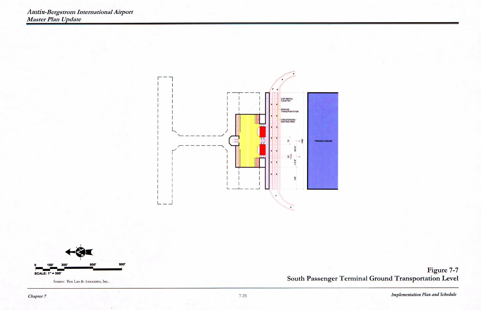
In view of heightened security measures imposed since September 11 that prevent meeters and greeters, well-wishers and general airport visitors from going through security checkpoints and entering the concourse, a general waiting area for the above group of people should be provided in the baggage claim level. This should include a general sitting area equipped with simplified food and beverage service, restroom facilities, TV monitors, telephone kiosks, flight information display and baggage information display systems, etc. A positive claim policy may also be instituted to segregate the above non-traveling group from arriving passengers and arriving baggage. In this recommended terminal expansion plan, a generous space is also proposed on the lower level of the terminal below the baggage claim level. This level is intended to segregate the car rental agencies and other ground transportation services from arriving and departing passengers until or
Chapter 7
7-27
Implementation Plan and Schedule
Austin-Bergstrom International Airport Master Plan Update
unless the passengers are ready to use these facilities and services located on the lower level. Such a separation is intended to facilitate the movement of arriving passengers from the interior of the building to curbside for pick-up either by private vehicles allowed in the mid-level roadway or to curbside on the lower-most level roadway where taxis, and other ground transportation services are located.
This in essence describes the south terminal concept in terms of its functional distribution, characteristics and operational philosophy. As stated above, it should be understood that while dimensions such as length and depth of structures have been specified and depicted herein, the overall space layout is basically conceptual in nature at this stage of the Master Plan Update process. As such, it may not necessarily match program requirements previously presented in Technical Report 3. The facility requirements previously developed serve as general planning guidelines, and as previously mentioned are subject to refinement depending on a particular concept. The tragic events of September 11 have created a certain degree of uncertainty relative to several aspects of airline and airport operations that directly affect passenger processing characteristics and passenger movement patterns. These in effect, directly alter established planning assumptions and planning standards normal to airport planning studies and activities prior to September 11. Thus, changing spatial needs due to changing regulations, both government imposed, or airport and airline imposed, will require constant monitoring to be followed with conscious and sensible adjustment from time to time, to adapt to evolving aviation situations, including additional security concerns and directives. While the general plan layout, distance criteria, number of floor levels and the functional distribution of the various airport processing functions at the various levels are generally sound, the actual space calculations and determination will require more detailed programming efforts and reevaluation at the initiation of design and at the first sign of implementation. However, the concept will accommodate anticipated program requirements and is flexible such that it can also accommodate a potential hub should such an operation materialize.
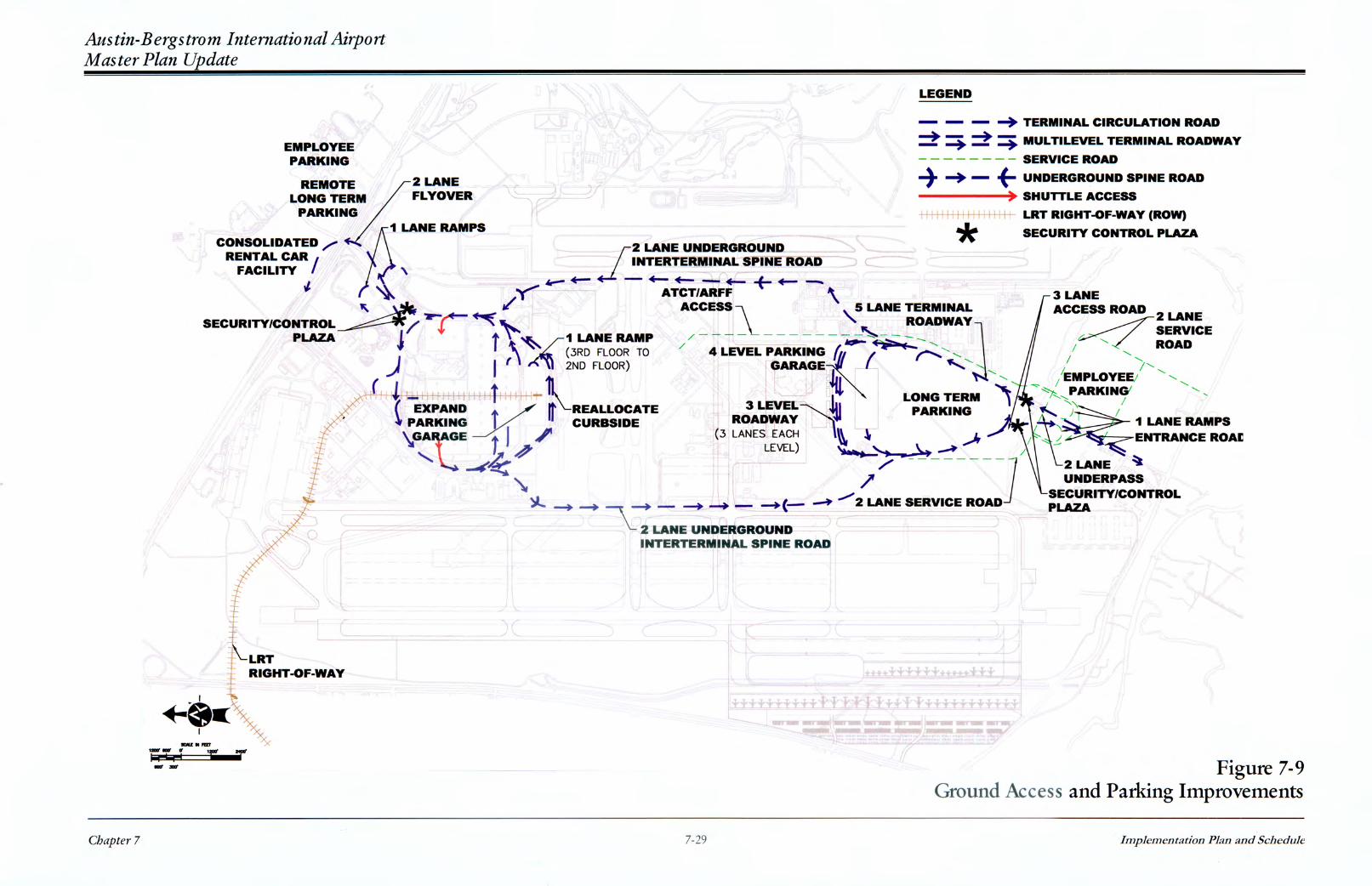
Recommended Ground Access Plan Overview The ground access component of the recommended development alternative provides for separate terminal access and loop road systems for the existing north terminal and the new south terminal. The existing terminal will continue to be served by Presidential Boulevard. A new two-lane flyover will be constructed connecting northbound Presidential Boulevard to westbound State Highway 71. The new south terminal will be accessed via a new terminal access and loop road to be constructed from Burleson Road. The curbside roadway system for the new south terminal will consist of three levels (Departures, Arrivals, and Commercial/Ground Transportation), while the existing two-level roadway system will continue to serve the existing north terminal. The roadway systems of each terminal can operate independently of each other. However, to facilitate vehicular movement between terminal buildings as well as to provide alternate access routes, the two terminals will be connected by two one-way partially underground spine roads. Figure 7-9 presents major access elements.
Chapter 7
7-28
Implementation Plan and Schedule
Austin-Bergstrom International Airport Master Plan Update
Access to each terminal loop road system will be controlled by new security/control plazas to be constructed on each terminal access road prior to the recirculation roadways. The new plazas will provide common entry and exit control points for all vehicle trip making within the terminal loop roads. Parking ticket dispensers will be provided on the entry plaza, and parking tollbooths on the exit plaza. In view of the heightened security requirements at airports, the new plaza will also have vehicle identification and surveillance equipment. This equipment will give the Airport the ability to track all vehicles within the terminal loop road system through either video and/or electronic means. The delays to airport traffic will be centralized at the plaza versus delays that are now being experienced at the exits from the various parking lots. Some additional delays will be experienced by traffic only destined for the terminals. In the case of the plaza for the north terminal road system, sufficient space is available between the tollbooths and SH 71 to allow for the peak hour queuing on inbound airport traffic. There will be a sufficient number of booths to limit the queue lengths to allow for the sight distance required to decelerate to a stop at the tollbooths from the SH 71 eastbound off ramp. The construction will require the replacement of several trees but also provides an opportunity to build an enhanced entryway into the Airport. Each terminal will have its own public parking and employee parking facilities. On the other hand, there will be a single consolidated rental car facility for both terminals, to be constructed north of State Highway 71. Access to airport ancillary uses in the vicinity of the existing north terminal will be provided by existing service roads (e.g., Spirit of Texas Drive and New Airport Drive). New service roads will be constructed for ancillary uses in the vicinity of the new south terminal. Service road traffic will not pass through the new terminal security/control plazas. Service roads will be connected to terminal access roads prior to the plazas so that traffic on the service roads that is destined for the terminals will pass through the security/control plazas. Regional access to the Airport will be provided by the existing State Highway 71 (SH 71), U.S. Highway 183 (US 183), Burleson Road, Farm-to-Market Road 973 (FM 973) and the proposed State Highway 130 (SH 130). SH 130 is a new major north-south toll facility to be constructed approximately two miles east of ABIA. The ground access plan reserves right-of-way for a future light rail transit (LRT) corridor to serve ABIA. North Terminal Access and Circulation The existing roadway and parking system currently serving the existing passenger terminal will be modified to accommodate projected 2020 traffic demand as well as to provide for increased airport security. These changes are described below. New SH 71/Presidential Boulevard Flyover. A new two-lane flyover will be constructed connecting northbound Presidential Boulevard to westbound SH 71. The flyover will diverge from Presidential Boulevard north of the new security/control plaza and merge with SH 71 prior to the Spirit of Texas Drive interchange. Traffic analysis indicated the need to construct the flyover as early as Planning Level 1 due to a projected operational deficiency at the SH 71/Presidential Boulevard
Chapter 7
7-30
Implementation Plan and Schedule
Austin-Bergstrom International Airport Master Plan Update
interchange as summarized in Chapter 4. Furthermore, traffic analysis showed the need for the flyover in Planning Level 3 even though ABIA traffic would be split between the existing and the new south terminals. This is due to the fact that passenger forecasts at the existing terminal under Planning Level 3 is approximately equal to Planning Level 1 passenger forecasts. New North Security/Control Plaza. In view of the heightened security requirements at airports, a new north security/parking control plaza will be constructed in both directions of Presidential Boulevard between New Airport Drive and the terminal recirculation road. The new plaza will provide a common entry/exit control point for all vehicle trip making within the terminal loop road. Parking ticket dispensers will be provided on the entry plaza, and parking tollbooths on the exit plaza. The new plaza will also have vehicle identification and surveillance equipment. The new plaza will have approximately six ticket dispensers on entry and 16 tollbooths on exit. When the new north plaza becomes operational, the existing North and South Parking Toll Plazas will be demolished. The existing entry control equipment for the parking lots and garage will be modified to conform to the centralized control at the new plaza. The new plazas will extend over the existing Presidential Boulevard on- and off-ramps to New Airport Drive. As a result, these ramps will be closed and new one-lane circular ramps will be constructed north of New Airport Drive. Access to the Ground Transportation Staging Area (GTSA) may continue to use the existing entrance off of Spirit of Texas Drive. As an option to ensure that all GTSA traffic passes through the new security/control plazas, access to the GTSA may be reconfigured from Spirit of Texas Drive to Presidential Boulevard. Furthermore, the inbound access ramp from Rental Car Lane to Presidential Boulevard would be closed for security purposes. This option is included in the plan as a long-term configuration. Until the Consolidated Rental Car Facility is constructed, rental car pick-up and returns will be routed through the Security/Control Plaza and as currently routed through the terminal circulation roadway system. Curbside Space Reallocation. The terminal curbside roadways at the existing north terminal will remain at two levels. The existing terminal curbside areas will continue to accommodate passenger loading/unloading at the existing north terminal for both private and commercial vehicle arrivals and departures. However, in order to accommodate the projected 11 MAP (60 percent of 18.4 MAP total for ABIA) at the existing north terminal, the following improvements to the existing terminal curbside areas will be necessary: • To provide additional curb space for private vehicles on the Arrivals Roadway, some of the
commercial curb spaces on this roadway will be relocated to the Departures Roadway, which is projected to have an excess of commercial curb spaces.
• The Departures Roadway currently has approximately 300 feet of unassigned curb spaces prior
to and beyond the private vehicle unloading area. These curb spaces will be converted to private
Chapter 7
7-31
Implementation Plan and Schedule
Austin-Bergstrom International Airport Master Plan Update
vehicle use. Furthermore, the existing charter bus area beyond the private vehicle unloading area will be relocated to the median curb to provide additional private vehicle curb space.
The existing Ground Transportation Staging Area (GTSA) will continue to function as the staging area for commercial vehicles serving the existing north terminal. However, as discussed above as an option, access to the GTSA may be reconfigured from Spirit of Texas Drive to Presidential Boulevard in the long-term to direct all GTSA traffic through the new security/control plaza. New North Parking Garage and Surface Lots. The third level of the existing parking structure, currently used for rental car ready/return, will ultimately be converted to public parking. The rental car ready/return area will be relocated to a new rental car facility when it is constructed as described below. During the interim years, the third floor and part of the second floor of the existing garage will be allocated to rental car ready/return. The existing parking structure will accommodate short term parking and part of the medium term parking demand. Additional medium-term parking may be provided by construction of two floors on the existing garage. As an option medium term parking demand can be accommodated in a new three-level parking garage to be constructed over the existing Express Lot A. The new garage would have pedestrian connections with the existing garage on all levels. Access to the new garage would be provided by the existing Express Lot A access road. The existing road between the Express Lot A and the long term lots would be reconfigured to be used by exiting traffic from both the new parking garage and the long term lots. The existing long term Lots B through G will continue to provide long term (more than 3 days) parking spaces for the existing terminal. Additional long term and overflow parking will be provided in a new remote lot to be developed north of SH 71. Passengers will be transported between the passenger terminal and the new remote lot via dedicated parking shuttles. Parking shuttles will continue to operate between the existing long term lots and the existing passenger terminal. However, parking shuttles will be rerouted to enter the lots from the east and exit on the west (instead of the existing route entering from the west and exiting on the east) to eliminate the redundant loop in the shuttle route and thereby reduce travel time and distance between the lots and the passenger terminal building. The existing travel route for parking shuttles starts with passenger pick-up in the parking lot, then exiting the parking lot on the east side of the terminal roadway loop, proceeding along the recirculation roadway, then the north and west sides of the loop to the terminal frontage road. After dropping off and loading new parkers, the shuttle proceeds along the east, north and west sides of the loop to the parking lot entrance on the west side. By relocating the shuttle entrance and exit to the east and north sides respectively, each shuttle trip can be shortened by approximately one mile and eliminates the shuttles traveling along the recirculation roadway and portion of the north side of the loop road where the heavy inbound traffic is merging and diverging to parking lot entrances. A new access route from Presidential Boulevard to the existing parking lots traversing the center spine has been considered. This center spine road would divide the existing parking lots into two areas and could hinder the smooth flow of private and shuttle vehicles between lots. Furthermore,
Chapter 7
7-32
Implementation Plan and Schedule
Austin-Bergstrom International Airport Master Plan Update
the distance between the security/control plaza and the center spine road is considered too short and will not provide the drivers adequate time for decision-making and lane-change maneuvers. In addition, the shuttle service for the existing lots is recommended to be rerouted to exit at approximately the center spine to allow shuttles to smoothly merge with Presidential Boulevard traffic. Therefore, the proposed development plan does not include the center spine access to the existing long term lots. A parking structure sensitivity study is recommended to be conducted to determine the appropriate rate structure for the garages, surface lots and remote lot. New Consolidated Rental Car Facility. A new 85-acre consolidated rental car facility will be constructed north of SH 71. This facility will serve both the existing north terminal and the new south terminal. Separate dedicated rental car shuttle routes will be provided for the existing north terminal and the new south terminal. The existing rental car ready/return (R/R) area on the third level of the existing garage as well as the existing rental car service areas on Rental Car Lane will be eventually relocated to the new facility. With rental car consolidation, all rental car concession spaces in the terminal and ready/return spaces in the existing garage will be relocated to the consolidated facility. The new rental car consolidated facility will have the following features: •
•
•
•
•
A common passenger building will serve all rental car customers (renting and returning). The building will have a common passenger area with amenities such as rest/waiting areas, and food/snack bars. Individual counters operated by rental car operators will be located within the building. A common rental car shuttle service will transport passengers between the consolidated facility and the passenger terminal building. This service could be provided either by the airport or operated jointly by the rental car companies. Shuttle loading/unloading curbs will be provided in front of the common passenger building. Shuttle bus staging area will be located adjacent to the loading/unloading curbs. A parking area will be provided in front of or adjacent to the passenger building for temporary storage of returned vehicles, with clearly marked spaces for each company. Company staff will drive the returned vehicles to the common service area or to the company’s own maintenance area. Another parking area will be provided adjacent to the passenger building for temporary storage of ready vehicles. This area will have clearly marked spaces allocated among the different operators. Company staff will drive ready vehicles from the common service area or from the company’s storage area to this ready parking area. Operators will have individual lots for vehicle maintenance and storage. These lots are envisioned to be located at the periphery of the consolidated facility.
The new consolidated facility will be constructed in Planning Level 2. Prior to this, rental car ready/return will be accommodated on the second (partly) and third floors of the existing garage. In
Chapter 7
7-33
Implementation Plan and Schedule
Austin-Bergstrom International Airport Master Plan Update
order to have a single entry point for the ready/return, a new semi-circular ramp will be constructed on the east side of the existing garage to connect the third floor to the second floor. Rental cars bound for the second floor will access the garage via the existing inbound ramp, and use the new ramp to go to the second floor ready/return area. Third floor egress will be provided by the existing egress ramp. Second floor rental car egress will be via the existing garage exits. New North Employee Parking Lot. Separate employee parking lots will be provided for the existing north terminal and the new south terminal. The north employee lot will be constructed on a 18-acre lot located north of SH 71. This lot will accommodate airline, terminal and concession employees related to the north terminal. Dedicated shuttles will transport employees between the lots and the terminal building. Other Airport Roads. Cardinal Loop (the extension of Presidential Boulevard north of State Highway 71) will be widened from two to four lanes to provide access to the new rental car facility, the new remote long term parking lot, and the new employee parking to be constructed north of SH 71. Spirit of Texas Drive will continue to provide access to the existing air cargo (via New Airport Drive and Cargo Avenue), ground support equipment maintenance (GSEM), fuel, and belly hold cargo facilities. New Airport Drive will continue to provide access to the existing Airport Hilton Hotel, as well as the relocated building maintenance and flight kitchen facilities east of the existing long term lots. Service Avenue will be relocated south of the existing in-flight kitchen area to provide access to the existing central plant and terminal delivery docks. This relocation is necessary since the new east spine road will cut across the existing Service Avenue. The new access should be fenced and provisions should be made for security checks of all vehicles entering and leaving the terminal delivery dock area. Golf Course Road will continue to provide access to the State Aircraft Pooling Board and the golf course. In addition, it will provide access to other new uses planned in the vicinity of the State Aircraft Pooling Board, including airline maintenance and general aviation. The proposed depressed northbound spine road between the north and south terminals will interrupt the service road to the loading docks at the north terminal. The service road will be rerouted to the south edge of the existing Central Plant and maintain the same road alignment from that point to the terminal loading docks. Transit and Shuttle Services. Shuttle services will be provided between the existing terminal building and the following areas: • • • • •
Existing long term parking lots New north long term parking lot New consolidated rental car facility New north employee parking lot New south terminal building
Chapter 7
7-34
Implementation Plan and Schedule
Austin-Bergstrom International Airport Master Plan Update
Parking shuttles serving the existing long term lots will be rerouted to enter the lots from the east and exit on the west (instead of the existing route entering from the west and exiting on the east) to eliminate the redundant loop in the shuttle route and thereby reduce travel time and distance between the lots and the passenger terminal building. Parking shuttles serving the new long term lot inside the new south terminal’s loop road will also be routed in similar fashion. Public bus transit services will continue to be provided by Capital Metro. Capital Metro has proposed a Light Rail Transit (LRT) route terminating at the airport. Implementation of the LRT is still subject to funding availability. However, LRT right-of-way is reserved in the recommended ground access plan. The proposed ROW alignment would originate from the northwest boundary of the airport property. From this point, it would traverse a westerly direction parallel to SH 71, crossing the north runway protection zone of Runway 17R-35L in a tunnel, and emerging to surface level at approximately the north end of New Airport Drive. It would transition to an elevated facility in order to cross Spirit of Texas Drive, and remain elevated as it traverses along the center spine of the existing long term lot within the Presidential Boulevard loop and terminate within the existing garage. Traffic Circulation. Inbound traffic associated with the existing terminal will use SH 71 and Presidential Boulevard as the primary access to the terminal. Terminal traffic using Spirit of Texas Drive will use the new (loop) ramp from New Airport Drive that merges with Presidential Boulevard prior to the security plaza. All terminal traffic on Presidential Boulevard will go through the security/control plaza. Privately owned vehicles (POVs) will be issued time-stamped tickets at the entry gates. Commercial, transit and shuttle vehicles will be automatically detected by the Automated Vehicle Identification (AVI) system. POVs can then proceed to the terminal parking garages or surface lots, or to the terminal curbside. POVs entering the garage/surface lot will go through ticket validating machines to identify the parking location. Exiting vehicles from the parking garages/lots will use the egress roadways to be constructed in the vicinity of the existing South Toll Plaza. The existing North Toll Plaza will be closed to exiting traffic. Terminal curbside traffic will use the existing egress ramps and merge with exiting parking traffic. Traffic can then recirculate back to the terminal, or go to the exit plaza. POVs will be assessed the corresponding parking fee based on the time-stamped and parking area validated tickets. After exiting the toll plaza, traffic can either (a) use the new flyover to westbound SH 71, (b) take Presidential Boulevard to eastbound SH 71 or straight to Cardinal Loop; or, (c) use the loop off-ramp to New Airport Drive to access the Hilton Hotel and airport ancillary uses. After going through the security/control entry plaza, commercial vehicles can proceed to the terminal curbside to pick up or drop off passengers, or proceed directly to the GTSA via the new access off Presidential Boulevard. From the terminal curbside, they can either (a) exit the airport via the exit toll plaza, (b) recirculate back to the GTSA, or (c) proceed to the new south terminal via the underground west spine road. GTSA vehicles can access the Presidential Boulevard loop and the west spine road via the existing ramp at Rental Car Lane.
Chapter 7
7-35
Implementation Plan and Schedule
Austin-Bergstrom International Airport Master Plan Update
Parking shuttles from the terminal curbside will enter the existing long term lots via the new access road east of the lots, and exit the lot via the new egress off the existing central parking lot collector roadway. Shuttle routes within the long term lots will be designed to be as short as possible to reduce travel time within the lots, but be accessible within 500 feet walking distance from any point inside the lot. Rental car return vehicles will proceed to the new consolidated facility north of SH 71 via Cardinal Loop. Passengers will then be transported to their respective terminal buildings by dedicated shuttles. POVs using the north remote lot will proceed to this lot via Cardinal Loop. Passengers will then take the parking shuttle to the terminal building. North terminal employees will proceed to the north employee lot and take the employee shuttle to the terminal. New South Terminal Access and Circulation New South Terminal Access Road. Primary access to the new south passenger terminal will be provided via Burleson Road. A new terminal access road will be constructed from Burleson Road. The inbound access roadway would have approximately the same alignment as the existing General Aviation Avenue. The south access road will be a divided roadway with two lanes in each direction for a total of four lanes from Burleson Road to the south security/control plazas. The intersection of the new south access road and Burleson Road will be improved and signalized to accommodate traffic associated with the new south terminal and adjacent ancillary uses. The south service road will be elevated in the vicinity of the south control plaza to cross over the south access road. Burleson Road is planned to be improved to a four-lane arterial road in the CAMPO 2025 Transportation Plan. It is recommended that a traffic study be conducted to identify the regional roadway improvements associated with the proposed airport development plan. The traffic study would provide a better estimate of the traffic distribution in the vicinity of ABIA as a result of the new south terminal and the proposed SH 130 tollway through the use of the CAMPO Regional Traffic Model. New South Security/Control Plaza. A new security/control plaza will be constructed in each direction of the south access road. The plazas will be located south of the recirculation roadway for the new south terminal. The south plaza will have four entry gates and eight exit gates. New South Terminal Loop Road. The south terminal loop road system will have five lanes between the recirculation road and the garage access points. Two lanes will be provided on the recirculation section of the south terminal loop road. Access to the terminal curbside roadways will be provided by one-lane ramps to each level. Separate access/egress ramps or roadways will be provided for the parking garage, long term parking, and the hotel, all of which are located within the new terminal loop road. These ramps/roadways will generally consist of one lane each, except for the garage which requires two lanes.
Chapter 7
7-36
Implementation Plan and Schedule
Austin-Bergstrom International Airport Master Plan Update
New Three-Level Terminal Roadway. The new south terminal will have a three-level roadway system. The upper level roadway will be used by departure traffic. The middle level roadway (above grade) will be used by arrival traffic. The lower level roadway (at grade) will accommodate commercial vehicles (for-hire shuttles, bus transit, as well as parking, employee and rental car shuttles), effectively operating as the Ground Transportation Center for the new south terminal. The upper (departures) and middle (arrivals) level roadways will have the same lane configuration, consisting of one 20-foot curb lane (effectively allowing double parking for loading/unloading), two 12-foot through travel lanes, and a six-foot shoulder/clearance for a total of 50 feet curb-to-curb. The lower (commercial) level roadway will consist of one 15-foot curb lane, one 14-foot through travel lane, and a six-foot shoulder/clearance for a total of 35 feet curb to curb. The wider lane dimensions for the commercial roadway are intended to provide adequate clearance for large shuttles and buses. As a design option, the lower (commercial) level roadway can be developed as a Ground Transportation Center for the new south terminal, with separate parallel 20-foot islands designated for different types of ground transportation services. This design option would not require changes to the three-level roadway structure. New Parking Garage and Surface Lots. A new four-level parking structure will be constructed for the new south unit terminal. This structure will have approximately the same building footprint as the existing parking structure and will accommodate both short term and medium term parking. Garage access and egress will be provided by two-lane roads. The garage access road will have gates equipped with ticket validating machines. A new 54-acre long term parking lot will be constructed south of the new parking structure. This lot will accommodate the projected long term parking demand in the new south terminal area. The aforementioned parking lot/structure, as well as a potential new hotel, will be located inside the new terminal loop road system. Dedicated parking shuttle services will be provided between the long term lot and the new south terminal. An area of 35 acres is preserved for a remote parking lot on the northeast quadrant of Burleson Road and General Aviation Avenue. This lot will be accessed directly from Burleson Road, as well as indirectly from General Aviation Avenue via the east service road. This remote lot will provide overflow parking spaces during peak summer and holiday seasons. Dedicated parking shuttles will also serve this lot. New South Employee Parking Lot. A new 12-acre south employee parking lot will be constructed on the northeast quadrant of General Aviation Avenue and Burleson Road. This lot will accommodate airline, terminal and concession employees of the south terminal. Dedicated shuttles will transport employees between the lot and the south terminal.
Chapter 7
7-37
Implementation Plan and Schedule
Austin-Bergstrom International Airport Master Plan Update
Transit and Shuttle Services. Shuttle services will be provided between the new south terminal building and the following areas: • • • • •
New south long term parking lot New south remote parking lot New consolidated rental car facility New south employee parking lot Existing north terminal building.
Parking shuttles serving the long term lot within the terminal loop road will be routed to enter the lot from the west and exit on the east to eliminate the redundant loop in the shuttle route and thereby reduce travel time and distance between the lots and the passenger terminal building. Public bus transit services for the new south terminal will have to be arranged with Capital Metro. Capital Metro could extend the current routes serving the existing terminal to serve the new south terminal, or create new bus routes along Burleson Road. As discussed earlier, the proposed ground access plan reserves right-of-way for a future LRT line terminating at the north terminal garage. The extension of the LRT line to the new south terminal does not appear to be feasible due to the relatively few passengers and the high construction cost. However, the initial terminal shuttle will provide transit-type service from the north terminal to the south terminal. The possible LRT extension to the south terminal should be subject to a feasibility study at the time the service is provided. New South Support Area Service Roads. Two-lane two-way service roads will be constructed to provide access to airport ancillary uses on both sides of the new terminal loop. The service roads will be connected via ramps to the new terminal loop road system in the vicinity of the south security/control plaza. It is envisioned that the new terminal access road will be elevated in the vicinity of the control plaza to be able to cross over the service road which will be constructed at ground level. The east service road will serve the existing general aviation, and the future remote overflow and employee parking areas located east of General Aviation Avenue. The west service road will serve the future DOA Administration, field maintenance, GSEM, fuel farm, and belly hold cargo facilities that are located west of the new terminal loop road. Access to the airport traffic control tower and adjacent uses between the cross-taxiways will be provided by a two-lane two-way road from the south end of the east inter-terminal spine road. This road will be at-grade throughout most of its length and will run below ground level across the new cross-taxiways. The road will have gate control immediately after the diverge from the spine road. Loading dock deliveries to the south terminal will have access from the new ARFF/ATCT access road. Burleson Road and the new south terminal access road will provide access the new Texas Air National Guard (TANG) permanent site located on the northwest quadrant of Burleson Road and General Aviation Avenue.
Chapter 7
7-38
Implementation Plan and Schedule
Austin-Bergstrom International Airport Master Plan Update
US Highway 183 will provide access to future air cargo and/or other uses to be developed in the vicinity of the US Highway 183/Burleson Road intersection. Traffic Circulation. Traffic associated with the new south terminal will use Burleson Road and the new south access road as the primary access to the terminal. All terminal traffic will go through the south security/control entry plaza. Privately owned vehicles (POVs) will be issued time-stamped parking tickets via ticket dispensers. Commercial vehicles and shuttles will be automatically detected by the Automated Vehicle Identification (AVI) system installed at the plaza. POVs can then proceed to the terminal parking garage or surface lots, or to the terminal curbside. POVs entering the garage/surface lot will go through ticket validating machines at the entrance to the parking area. The machine will stamp the parking area used. Exiting POVs from the parking garages/lots will use the egress roadways which will not have control gates but will be fitted with on-road equipment to prevent vehicle entry. These vehicles can then proceed to the south exit plaza or recirculate back to the terminal curbside. Roadway signage will direct terminal curbside traffic to the appropriate level. All commercial, transit and shuttle vehicles will be directed to the lower (commercial) roadway level. Arrivals traffic will be directed to the middle level. Departures traffic will be directed to the upper level. POVs on the terminal curbside can then exit the airport via the south exit plaza, or recirculate back to the parking areas. Exiting POVs will be assessed the corresponding parking fee at the plaza based on the time-stamp and validated parking location. Exiting commercial vehicles will be automatically detected by the Automated Vehicle Identification (AVI) system installed at the plaza. After the toll plaza, POVs will exit the Airport via Burleson Road. Traffic going to the airport ancillary uses can use the ramp to the service road. Rental car return vehicles will proceed to the new consolidated facility north of SH 71 via Cardinal Loop. Rental car return vehicles that use Burleson Road will be directed to the new facility. Passengers will then be transported to their respective terminal buildings by dedicated shuttles. South terminal employees will proceed to the south employee lot and take the employee shuttle to the terminal. Inter-Terminal Spine Road The new south passenger terminal will be connected to the existing passenger terminal via two one-way spine roads to be constructed partly underground and on alignments approximately parallel to the runways. Each spine road will have two lanes and emergency shoulders. The east spine road will flow in a one-way northbound direction from the new south terminal to the existing terminal. It will diverge from the south terminal loop road prior to the access ramps to the curbside roadways, and merge with the existing north terminal loop road in the vicinity of the existing flight kitchen facility. The underground section of the east spine road will be approximately 4,000 feet long. The east spine will transition from underground to at-grade level in the vicinity of the existing flight kitchen facility
Chapter 7
7-39
Implementation Plan and Schedule
Austin-Bergstrom International Airport Master Plan Update
and will impact that facility and the existing Service Avenue. The existing flight kitchen facility will be relocated across Service Avenue. The existing Service Avenue will be closed and a new two-lane service road will be constructed connecting New Airport Drive to the existing terminal dock. The west spine road will flow in a one-way southbound direction from the existing terminal to the new south terminal. It will diverge from Presidential Boulevard in the vicinity of the existing fuel farm, and transition to an underground level in the vicinity of the existing belly freight facility. The underground section of the west spine road will be approximately 4,300 feet long. It will transition from below-ground to at-grade level in the vicinity of the proposed south central plant and belly hold cargo area, and merge with the south terminal loop road. The west spine road will impact the existing belly freight facility, which will be reconfigured to accommodate the west spine road alignment.
Demolition and Site Preparation
Anticipated demolition required to complete improvements include existing facilities to be replaced and facilities remaining from the original airforce base operations. Existing buildings, roadways, storm drainage, and airfield pavement demolition quantities were tabulated by existing facility. Demolition required for the proposed south passenger terminal and the general aviation facility were included with those facilities. The remaining demolition items were identified as “Other Demolition” since they are difficult to associate with any specific proposed facility. Demolition generally consists of rental car, Field Maintenance, TANG, Solid Waste, airfield, Building Maintenance, employee parking, general aviation, and various items associated with the terminal (e.g. water quality pond, fire suppression system, and trash compactor). Overall demolition consists of approximately 505,000 square feet of building, 410,000 square yards of airfield pavement, and 600,000 square yards of roadway and parking lot asphalt or concrete pavement. Site preparation was also estimated for each proposed facility. Since demolition is categorized separately, the remainder of site preparation work is minimal in most cases. Exceptions to this would include development in the following areas: •
•
•
Landfill areas. The plan does not currently call for improvements within the landfill so no such costs have been identified. While such costs are beyond the planning period, they will eventually need to be incurred upon the ultimate development of the Airport. Fill areas near the Colorado River (north of the airport). These fill areas were in essence a dumping site for left over fill from previous construction projects. It is our understanding that the fill was placed without compaction and contains various materials including trash, debris, pavement, and building materials. Due to the instability of this fill area and the expense required to remove and replace the fill with uniform, compacted material, the cost estimate assumed that improvements north of the airport would avoid this fill area. The area west of the West Runway System. The existing grading conditions in this area will require significant earthwork to prepare the site for development. This cost is included separately in the estimate for the proposed air cargo improvements.
Chapter 7
7-40
Implementation Plan and Schedule
Austin-Bergstrom International Airport Master Plan Update Utilities
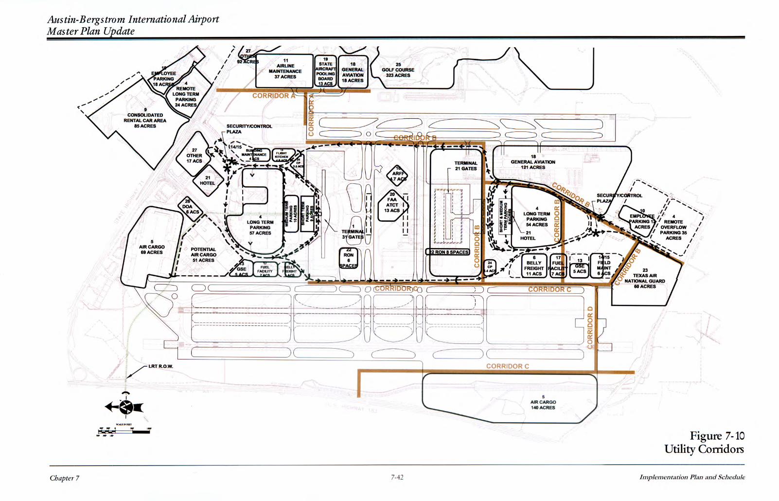
Anticipated utility infrastructure improvements consist of water, wastewater, gas, electric and telecommunications mains to serve new and expanded facilities. For cost estimating purposes, four main corridors have been identified for significant utility infrastructure improvement, with secondary lines extending from these main corridors or connecting to existing utility lines. The four main corridors, shown on Figure 7-10, run primarily north south and consist of the following general alignments. Corridor A. From SH 71 to between the State Pooling Board and East Runway System, this consists of water, wastewater, gas, electric and telecommunications mains to serve the proposed airline maintenance and general aviation facilities. Corridor B. Along the proposed east interterminal connector road parallel to the East Runway System continuing along General Aviation Avenue to Burleson Road – consisting of (1) water, wastewater, gas, electric and telecommunications mains along General Aviation Avenue and secondary lines running east to serve the proposed south terminal and proposed facilities developed between the south terminal and Burleson Road; and (2) relocation of electric, gas, and water lines for the development of the east interterminal connector road. Corridor C. Along the proposed west interterminal connector road parallel to the West Runway System – consisting of water and telecommunications mains to serve proposed facilities developed between the south terminal and Burleson Road. Water main connections to Corridor B would provide a looped water system. Corridor D. Between the West Runway System and proposed west side cargo area to Burleson Road – consisting of water, wastewater, gas, electric and telecommunications mains to serve the west side cargo facility. Additional utility work includes relocating an overhead electric transmission main and storm drainage channel currently running through the proposed west side cargo area. These two relocations are included under the cost for development of air cargo facilities. Costs associated with the overhead electric transmission main relocations were obtained from Austin Energy. Costs associated with relocation of the storm drainage channel assume replacement with another storm drainage channel rather than a piped system, due to the significant cost difference between the two systems.
Land Acquisition
The preferred development alternative includes acquisition of property to accommodate proposed improvements. Specifically this involves acquisition of approximately 85 acres north of SH 71 as previously shown on Figure 6-2. This is required for rental car and parking facilities with the exact locations to be determined. This acquisition is in addition to properties currently planned for acquisition by DOA as part of the noise mitigation program. One residential property and a junkyard on the south part of the airport are also proposed for acquisition. This involves a one acre parcel west of Runway
Chapter 7
7-41
Implementation Plan and Schedule

Austin-Bergstrom International Airport Master Plan Update
17R-35L that is required for development of the west cargo area, and a 2.78 acre parcel along General Aviation Avenue.
PHASED DEVELOPMENT PROGRAM
The recommended development plan described in the previous subsection will be implemented in three distinct stages that correspond with Planning Levels 1, 2 and 3. There are two major components of the implementation program with the first being a development schedule that describes the type and magnitude of development projects contained in each development stage. The second component is the estimated construction costs for each development phase, which will be presented in a following sub-section of this chapter. It should be noted that while the development schedule set forth herein corresponds to the activity associated with the different planning levels, the implementation of development will depend on the achievement of the planning levels. The “trigger points” identified in the planning process and addressed in Chapter 4 should be considered in the implementation planning to provide sufficient lead time to ensure facilities are available when needed. The phasing of airfield, passenger terminal, auto parking and support facilities is graphically shown in Figure 7-11. Figure 7-12 presents the phasing of airport roadway improvements.
Planning Level 1 Planning Level 1 corresponds with the high growth forecast for the year 2005 and reflects 11 MAP, 147,200 annual tons of enplaned cargo and approximately 268,800 aircraft operations. The Planning Level 1 development includes the following major elements which are shown in blue on Figure 7-11 and identified by a blue symbol on Figure 7-12. Airfield The airfield projects implemented in the first development phase are: • Construct high-speed exit taxiways for Runway 17R-35L. • Construct Runway 35L departure pad/deice area with dual entrance taxiway capability. • Construct dual parallel taxiway for Runway 17L-35R. • Install CAT III ILS for Runway 17R. • Construct first phase of parallel taxiway and exit taxiways on west side of Runway 17R-35L to
support new cargo complex. • Construct access taxiway on east side of Runway 17L-35R to serve future airline maintenance
area. • Relocate RTR-3.
Chapter 7
7-43
Implementation Plan and Schedule