
Introduction and Experiments on Transmitter … · Introduction and Experiments on Transmitter...
25
Introduction and Experiments on Transmitter Localization with TDOA Stefan Scholl, DC9ST 1 Software Defined Radio Academy, Friedrichshafen, Germany, 07/2017
Transcript of Introduction and Experiments on Transmitter … · Introduction and Experiments on Transmitter...

Introduction and Experiments on Transmitter Localization
with TDOAStefan Scholl, DC9ST
1Software Defined Radio Academy,
Friedrichshafen, Germany, 07/2017

Basic Idea of TDOA
• TDOA = Time-Difference-of-Arrival (Multilateration)
• use several receivers and
• analyze time difference of received signal
• apply geometry to determine position of transmitter
RX 1
RX 2
RX 3
time
RX 1
RX 2RX 3
TDOA (1,2)
TDOA (1,3)
TDOA (2,3)
2

Multilateration: Basics
TDOA = 0 nsdifference in distance = 0 m„TX has equal distance to RX1 and RX2“All possible TX positions: straight line
Receiver 1 Receiver 2
Simplified Situation: Only 2 Receivers
RX 1
RX 2
3

Multilateration: Basics
Simplified Situation: Only 2 Receivers
Receiver 1
TDOA = 6.7 us (2000 m)„TX is 2000 m closer to RX1 than to RX2“Possible TX positions: hyperbola
=> 3 Receivers required to solve ambiguities
TDOA = 0 ns
RX 1
RX 2
Receiver 2
TDOA = -6.7 us (-2000 m)„TX is 2000 m farther away from RX1 than RX2“Possible TX positions: hyperbola
RX 1
RX 2
4

Multilateration: BasicsFull system with 3 receivers
Receiver 1 Receiver 2
Receiver 3
unique transmitter location
hyperbola forRX 1 & 2
hyperbolafor RX 1 & 3
hyperbola forRX 2 & 3
5Note: Synchronization of RXes required!

Delay Measurement
• How to measure delay between two signals?
• Correlation function
𝐶𝑜𝑟𝑟 𝜏 =
𝑡=0
𝑁−1
𝑠1 𝑡 𝑠2(𝑡 + 𝜏)
s1(t), s2(t): received signals by RX1 and 2
• „Tries every possible delay and records how good the signals match“
• Example:
• Peak -> best match, most likely delay 6
Correlationtwo signals
delay betweenthe two signals
=>
time t delay 𝜏s1(t)s2(t+ 𝜏)

Resolution Analysis
Resolution of delay measurement ≠ Resolution of localization on map!
TDOAs here: in steps of 600 m
good accuracy
bad accuracybad accuracy
600 m
=> good accuracy in area surrounded by receivers 7
300 m

Summary on Basics
• Theory:• TDOA analyzes time differences of signal arrival• requires 3 synchronized receivers• difference /delay measurement with correlation• good accuracy in area surrounded by RXes
NEXT:
• Praxis:• How to build a real system• Receiver setup, synchronization and connection• Signal processing• Results
8

Low Cost TDOA System: Overview
• Goal: Localize transmitter in the city of Kaiserslautern, Germany, withsimple system
• 3 Simple Receivers• Raspberry PI + RTL-Stick
• simple antenna
• antenna indoor
• correct frequency with „kalibrate-rtl“ (using GSM channel)
• newer versions of RTL-SDR: better frequency stability
• RTL-SDR Properties• receives any signals from 70 MHz to >1 GHz
• bandwidth 2 MHz
• achievable resolution for delay measurement
2 MHz sampling => 500 ns * 3e8 m/s = 150 m 9

Low Cost TDOA System: Receiver Placement
• standard indoor antenna• suboptimal placement in city-> very simple setup
expected area ofgood accuracy
10
Receivers

Low Cost TDOA System: Infrastructure
Master PC for RX control and(offline) signal processing
RX send back received data
High Data Rate Challenge:• RTL SDR: 8 Bit IQ, 2 MHz• => 16 Bit x 2 MHz = 32 Mbit/s• our available DSL upload: max. 1 Mbit/s
• 1s recording takes approx. 1/2 min to copy
Receiver 1 Receiver 2 Receiver 3
Master triggers reception at all RX
Internet / DSLconnection (via SSH)
11

Low Cost TDOA System: Synchronization
Reference Transmitter for RX Sync• DAB+ „Rotenberg“• mast height: 120 m• 217 MHz, 2 kW• 1.54 MHz bandwidth• excellent correlation!
-> very good for synchronization
12

Low Cost TDOA System: Synchronizationreference signalfor synchronization
unknown signalto localize
seamless frequencyswitching required!
Is seamless switching possible with the RTL-SDR?librtlsdr (c lib to talk to RTl-SDR) crashed, when modified to switch frequencies during reception
Yes! Solution:use branch async-rearrangements, https://github.com/mutability/librtlsdr/tree/async-rearrangementsSeamless switching works perfectly fine:Download of modified lib at: http://www.panoradio-sdr.de/tdoa-transmitter-localization-with-rtl-sdrs/
Reception at eachreceiver
DAB+ DAB+?
Synchronization: 1. start reception at RXes roughly the same point in time2. align received signals along reference signal (+ known delay to reference TX)-> Received signals get synchronized, not the RXes themselves!
time
13
1.2e6 samples 1.2e6 samplesoptional:for checking synchronizationor re-synchronization

Correlation of Real Signals
• Quality of correlationdependens on
• Noise / SNR
• Signal length
• Signal bandwidth
• Multi-Path Propagation
• Signal content !
• Correlation may have:• multiple ambiguous peaks
• no distinct peaks
good:well defined peak
bad:many broad peaks
Real signals received by 2 RTL-SDRs at different locations
14

Improvements On Correlation
• any peak could be the true delay!
• Analyse absolute delay values:
delay between peaks: here 61.000 samples = 9150 km,
max possible TDOA is distance between RXes, here a few kilometers!
use smoothingto determineprecise peak
15

Signal Processing
• Matlab script running on Master PC
• consider receptions pairwise to create a hyperbola
1. receive signals & send to master
2. synchronize RXs:• interpolate reference signals (optional)
• calculate correlation (dphase or abs)
• discard invalid peaks of correlation function
• use measured delay to synchronize
3. measure unknown signals• interpolate signals (optional)
• correlation (dphase or abs)
• discard invalid peaks of correlation function
• determine TDOA in samples and distance
4. calculate hyperbola using geometry
5. create a html / javascript file for google maps to display results 16

Results: 70cm DMR Repeater• DMR Repeater of Univ. of Kaiserslautern
• 439.4 MHz
• 12.5 kHz bandwidth, 4 FSK modulation
true position
17

Results: mobile telephony
• 922.8 MHz
• GSM/UMTS/LTE ??
Stars mark all basestations
18

Results: FM broadcasting
true position
• 96.9 MHz
• FM broadcast station, „Antenne Kaiserslautern“
difficult localization:Tx is located outsideof the receiver area:TDOA = Direction finding
19

Results: unknown signal
• 391 MHz
• BW estimate: ~15 kHz
post office & train station,are nearby (?)
20

Summary
21
• TDOA system can be built with little effort
• Simple RTL-SDR receivers are sufficient
• Remarkable results even with highly suboptimal setup
22
Further information and project files available:
http://www.panoradio-sdr.de/tdoa-transmitter-localization-with-rtl-sdrs/
Email: [email protected]

23

Correlation in Time Domain
24
signals aligned according to correlation peak (DAB+ recorded by 2 RTL-SDRs)
correlation of the two signals above
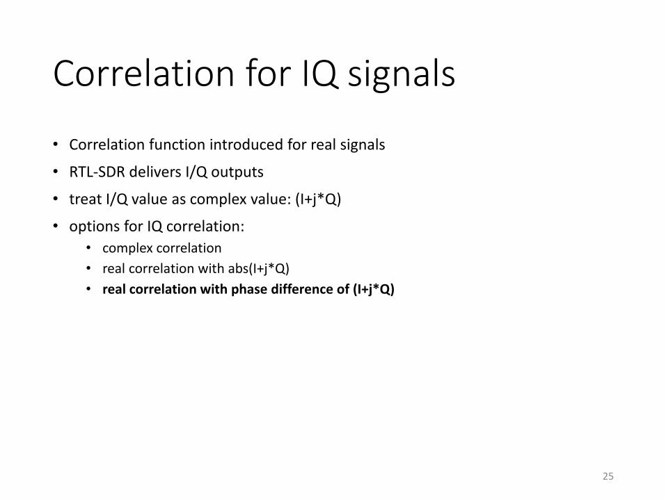
Correlation for IQ signals
• Correlation function introduced for real signals
• RTL-SDR delivers I/Q outputs
• treat I/Q value as complex value: (I+j*Q)
• options for IQ correlation:
• complex correlation
• real correlation with abs(I+j*Q)
• real correlation with phase difference of (I+j*Q)
25


