INTRODUCTION - American Best Pool Supply
17
Transcript of INTRODUCTION - American Best Pool Supply


1
INTRODUCTION
The spa that you have purchased is one of the very best available, and incorporates features designed to assure long, enjoyable and healthful use if properly operated and maintained.
The following instructions are intended to familiarize you
with important facts, measures and procedures, which will guide you in the use and necessary care of your spa. Your attention is particularly directed to the important safety instructions in this manual. We strongly urge you to become thoroughly familiar with prescribed safety practices and carry them out as specified within this manual.
Your spa and control equipment incorporates the finest
components available, and is designed in a manner to provide maximum enjoyment, ease of operation and years of trouble free operation.
2
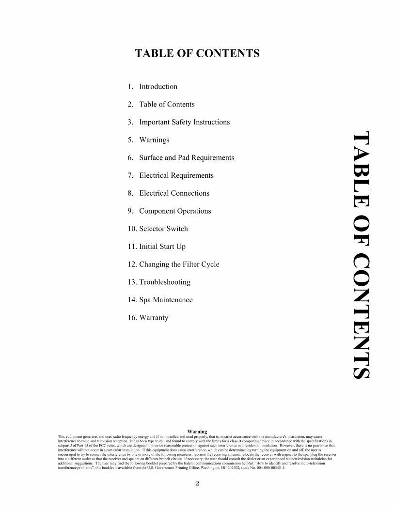
TABLE OF CONTENTS
1. Introduction
2. Table of Contents
3. Important Safety Instructions
5. Warnings
6. Surface and Pad Requirements
7. Electrical Requirements
8. Electrical Connections
9. Component Operations
10. Selector Switch
11. Initial Start Up
12. Changing the Filter Cycle
13. Troubleshooting
14. Spa Maintenance
16. Warranty
Warning This equipment generates and uses radio frequency energy and if not installed and used properly, that is, in strict accordance with the manufacture's instruction, may cause interference to radio and television reception. It has been type tested and found to comply with the limits for a class B computing device in accordance with the specifications in subpart J of Part 15 of the FCC rules, which are designed to provide reasonable protection against such interference in a residential insulation. However, there is no guarantee that interference will not occur in a particular installation. If this equipment does cause interference, which can be determined by turning the equipment on and off, the user is encouraged to try to correct the interference by one or more of the following measures: reorient the receiving antenna, relocate the receiver with respect to the spa, plug the receiver into a different outlet so that the receiver and spa are on different branch circuits, if necessary, the user should consult the dealer or an experienced radio/television technician for additional suggestions. The user may find the following booklet prepared by the federal communications commission helpful: “How to identify and resolve radio-television interference problems”, this booklet is available from the U.S. Government Printing Office, Washington, DC 202402, stock No. 004-000-00345-4.
TA
BL
E O
F CO
NT
EN
TS

3
IMPORTANT SAFETY INSTRUCTIONS
1. READ AND FOLLOW ALL INSTRUCTIONS.
2. WARNING: PEOPLE WITH
INFECTIOUS DISEASES SHOULD NOT USE A SPA OR A HOT TUB.
3. WARNING: TO AVOID INJURY
EXERCISE CARE WHEN ENTERING OR EXITING THE SPA OR HOT TUB.
4. WARNING: DO NOT USE A SPA
OR A HOT TUB IMMEDIATELY FOLLOWING STRENUOUS EXERCISE.
5. WARNING: PROLONGED
IMMERSION IN A SPA OR HOT TUB MAY BE INJURIOUS TO YOUR HEALTH.
6. CAUTION: MAINTAIN WATER CHEMISTRY IN ACCORDANCE WITH MANUFACTURER’S INSTRUCTION.
7. WARNING- To reduce the risk of injury, do not permit children to use this product unless they are closely supervised at all times.
8. A wire connector is provided on this unit to connect a minimum no. 8 AWG solid copper conductor between this unit and any metal equipment, metal enclosures of electrical equipment, metal water pipes or conduit within 5 feet (1.5m) of the unit.
9. WARNING- For indoor use only. This unit is not intended for outdoor use. IM
POR
TA
NT
SA
FET
Y IN
STR
UC
TIO
NS
4
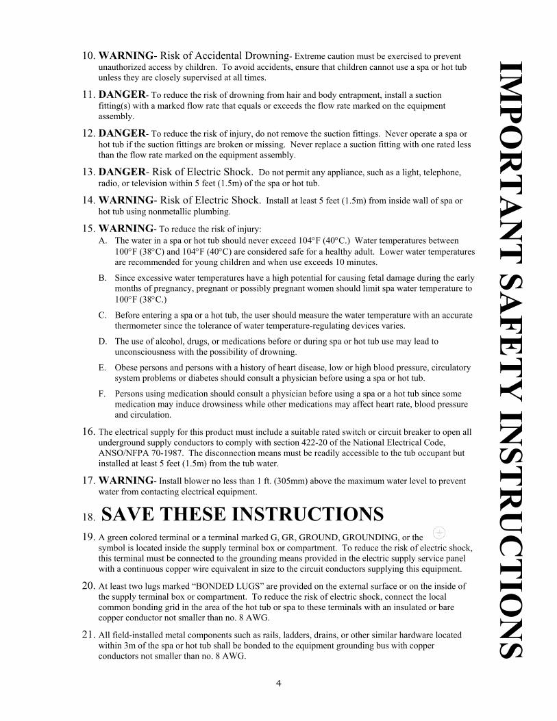
10. WARNING- Risk of Accidental Drowning- Extreme caution must be exercised to prevent unauthorized access by children. To avoid accidents, ensure that children cannot use a spa or hot tub unless they are closely supervised at all times.
11. DANGER- To reduce the risk of drowning from hair and body entrapment, install a suction fitting(s) with a marked flow rate that equals or exceeds the flow rate marked on the equipment assembly.
12. DANGER- To reduce the risk of injury, do not remove the suction fittings. Never operate a spa or hot tub if the suction fittings are broken or missing. Never replace a suction fitting with one rated less than the flow rate marked on the equipment assembly.
13. DANGER- Risk of Electric Shock. Do not permit any appliance, such as a light, telephone, radio, or television within 5 feet (1.5m) of the spa or hot tub.
14. WARNING- Risk of Electric Shock. Install at least 5 feet (1.5m) from inside wall of spa or hot tub using nonmetallic plumbing.
15. WARNING- To reduce the risk of injury: A. The water in a spa or hot tub should never exceed 104°F (40°C.) Water temperatures between
100°F (38°C) and 104°F (40°C) are considered safe for a healthy adult. Lower water temperatures are recommended for young children and when use exceeds 10 minutes.
B. Since excessive water temperatures have a high potential for causing fetal damage during the early months of pregnancy, pregnant or possibly pregnant women should limit spa water temperature to 100°F (38°C.)
C. Before entering a spa or a hot tub, the user should measure the water temperature with an accurate thermometer since the tolerance of water temperature-regulating devices varies.
D. The use of alcohol, drugs, or medications before or during spa or hot tub use may lead to unconsciousness with the possibility of drowning.
E. Obese persons and persons with a history of heart disease, low or high blood pressure, circulatory system problems or diabetes should consult a physician before using a spa or hot tub.
F. Persons using medication should consult a physician before using a spa or a hot tub since some medication may induce drowsiness while other medications may affect heart rate, blood pressure and circulation.
16. The electrical supply for this product must include a suitable rated switch or circuit breaker to open all underground supply conductors to comply with section 422-20 of the National Electrical Code, ANSO/NFPA 70-1987. The disconnection means must be readily accessible to the tub occupant but installed at least 5 feet (1.5m) from the tub water.
17. WARNING- Install blower no less than 1 ft. (305mm) above the maximum water level to prevent water from contacting electrical equipment.
18. SAVE THESE INSTRUCTIONS
19. A green colored terminal or a terminal marked G, GR, GROUND, GROUNDING, or the symbol is located inside the supply terminal box or compartment. To reduce the risk of electric shock, this terminal must be connected to the grounding means provided in the electric supply service panel with a continuous copper wire equivalent in size to the circuit conductors supplying this equipment.
20. At least two lugs marked “BONDED LUGS” are provided on the external surface or on the inside of the supply terminal box or compartment. To reduce the risk of electric shock, connect the local common bonding grid in the area of the hot tub or spa to these terminals with an insulated or bare copper conductor not smaller than no. 8 AWG.
21. All field-installed metal components such as rails, ladders, drains, or other similar hardware located within 3m of the spa or hot tub shall be bonded to the equipment grounding bus with copper conductors not smaller than no. 8 AWG.
IMPO
RT
AN
T SA
FET
Y IN
STR
UC
TIO
NS

5
WARNINGS • The use of alcohol, drugs, or medication can greatly increase the risk of fatal
hyperthermia in spas and hot tubs. • Persons suffering from heart disease, diabetes, high or low blood pressure, or any
other serious illness and pregnant women should consult with their physician before using a spa or hot tub.
• Excessive water temperature can be dangerous. • Never operate any electrical appliance from inside the spa or hot tub, or when wet. • Do not enter the spa while under the influence of alcohol and/or drugs. Persons on
medication should consult with their physician before entering the spa. • Observe a reasonable time limit in the spa. Long exposures at higher temperatures
can result in dizziness and/or hyperthermia. • Hyperthermia occurs when the internal temperature of the body reaches a level
several degrees above the normal body temperature of 98°F (36.7°C.) The symptoms of hyperthermia include dizziness, fainting, drowsiness or lethargy.
The affects of hyperthermia include: 1. Unawareness of impending hazards.
2. Failure to perceive heat. 3. Failure to recognize the need to exit spa. 4. Physical inability to exit spa. 5. Fetal damage in pregnant women. 6. Unconsciousness resulting in a danger of drowning.
• Always enter and exit a spa slowly. It is recommended not to use the spa alone. • The consumer product safety commission has stated that the water temperature in a
spa or hot tub should not exceed 104°F (40°C.) Immersion in water in excess of 104°F (40°C) can be hazardous to your health.
WA
RN
ING
S

6
SURFACE AND PAD REQUIREMENTS 1. Your new spa must be placed on a uniformly firm and level surface. The pad
foundation recommended is a concrete pad at least 4 inches thick. As an alternative, a pea-gravel foundation pad could be used, but it must be on a firm, level base and it must be contained in a secure wood or concrete restraining border so that the loose gravel can not shift once the spa is in place. If a concrete pad is poured, this is the logical time to “plumb-in” your electrical conduit. Be sure the concrete has cured for at least one week before setting the spa in place. A typical spa, filled with water, could weigh as much as two and a half tons and if the concrete is not fully cured, it could easily crack. An uneven or cracked concrete pad or the use of shims of any kind may cause the spa to buckle, distort and/or crack. If this being the case, the warranty on your spa will be void.
2. If your spa is located near water sprinklers, adjust the cap on them so water will not
hit the wood siding of the spa. 3. Balconies and decks must be constructed to current state and local codes to safely
support the maximum load of your water filled spa and the number of people using the spa. Check with your construction contractor for these specifications. Balconies and decks must support at least 75 pounds per square foot.
4. Gates must be self-closing and self-locking. Check your local codes regarding fences
and gates. 5. It is the responsibility of the owner to provide clear access on all sides of the spa once
it is set in place for ease in repair, otherwise, additional costs to service and repair the spa will be incurred.
INSTALLATION CONSIDERATIONS It is highly recommended that the owner/user of this spa carefully read all instructions in this manual prior to having your spa installed at your chosen location, whether indoors or outdoors. Improper installation may result in equipment damage and will void the warranty.
SUR
FAC
E A
ND
PAD
RE
QU
IRE
ME
NT
S

7
ELECTRICAL REQUIREMENTS
220 Volt 50 Amp Service 60 Hz 1 Phase 2 wire- L1, L2 & Ground – Dedicated 220V unit only (3 Wire- L1, L2, Neutral & Ground - Utilizes 220V and 110Vac components) No. 6 AWG supply wire is required No. 8 AWG conductor is required for bonding USE COPPER CONDUCTORS ONLY
110 Volt 20 Amp Service 60 Hz 1 Phase 2 wire- L1, Neutral, & Ground No. 12 AWG supply wire is required No. 8 AWG conductor is required for bonding USE COPPER CONDUCTORS ONLY It is the responsibility for the installer and the owner to install a readily accessible disconnecting means during the installation.
MOUNTING
Per UL 1563, paragraph 6.4.3, the AP-4 Indoor Spa Pack and the additional pump (Jets 2, optional) shall be mounted so that the lowest portion of any live part is a minimum of 4 in. above the mounting surface. CAUTION: THE EQUIPMENT AND CONTROLS SHALL BE LOCATED NOT LESS THAN 5 ft (1.5M) HORIZONTALLY FROM SPA OR HOT TUB.
EL
EC
TR
ICA
L R
EQ
UIR
EM
EN
TS
8
ELECTRICAL CONNECTIONS
110V/220V control system come pre-wired for 110V operation from the factory.
110/220 CONVERTIBLES
To change from 110V to 220V 1. Remove orange jumper running between L2 & Neutral in diagram #3 (this is
important.) 2. Install 220V supply line as per diagram #2. 3. If the system is on a 30 Amp/220V circuit breaker, leave conversion switch in the 30
Amp position. If the system is on a 50 Amp/220V circuit breaker, switch the conversion switch to the 50 Amp/220V position.)
All 110V dedicated systems have a 110V 20Amp power cord which must be plugged into a dedicated 110V 20 Amp receptacle.
NOTE: Always check local and state codes for wiring requirements that
may exceed N.E.C.
ELECTR
ICA
L CO
NN
ECTIO
NS
* NEUTRAL IS NOT REQUIRED ON DEDICATED 220V SYSTEMS
* Utilizes 220Vac and 110Vac components
9
COMPONENT OPERATIONS THERMOSTAT The thermostat is a highly precise temperature control. The spa’s thermostat is designed to provide you with optimum control of the spa water temperature. The maximum setting is approximately 104°F (40°C) 2% accuracy. As the knob is turned counterclockwise, the temperature will drop in ever increasing proportions. This geometric temperature scale allows you much greater precision and control at the upper temperature. We suggest that once you find the temperature you like best, identify its location on the control. JETS When the jet switch is activated, the pump is switched to high-speed operation. You will notice that, occasionally, when the pump is on high-speed and you press the “jets” button to turn it off, it continues to operate on low speed. This may be because the thermostat is calling for heat or the time clock is in a filtration cycle. BOOSTER PUMP (Optional) When the booster switch is activated, the booster pump is switched to High-speed operation. The second pump (booster) is a single-speed pump. AIR When the air switch is activated, the air blower will turn on/off. IMPORTANT: In both 30 Amp/220V and 20 Amp/110V systems, activating the jet (high speed pump) or the air blower will automatically de-activate the heater. In 50 Amp/220V systems, heating can take place during operation provided that the thermostat is set high enough to demand heat. LIGHT When the light switch is activated, the 12V-spa light will turn on/off. There are two color lenses included with your spa, which may be placed over the light lens.
CO
MPO
NE
NT
OPE
RA
TIO
NS

10
SELECTOR SWITCH (OPTION #1)
“Timed Filtration & Heat” and “Timed Filtration & Automatic Heat” TIMED FILTRATION & AUTOMATIC HEAT
The low speed pump, ozonator (optional) and heater will turn on automatically to maintain the current water temperature. The low speed pump and ozonator (optional) will also run during the filter cycle(s) that are set on the time clock. (See “Setting the Time Clock for Filtration” for further details) TIMED FILTRATION & HEAT
The low speed pump will turn on during the filter cycle. Heating is automatically controlled by the loss of temperature during the filter cycle(s). If your system is 50 Amp/220V and you wish to heat outside of the filter cycle, the pump must be activated manually and the thermostat turned up to the desired temperature.
SELECTOR SWITCH (OPTION #2)
“Continuous Mode” and “Timer Mode”
CONTINUOUS MODE The low speed pump will always be filtering the spa unless the jet switch is
activated. While in this mode if the water temperature drops or the thermostat is turned up, the heater will turn on automatically to heat the spa water. TIMER MODE
The thermostat solely controls the low speed pump and the heater. Example: If the thermostat is turned up the low speed pump will turn on followed by the heater. Once the temperature is met the heater and low speed pump will turn off.
SELECTOR SWITCH (OPTION #3)
“Time Clock Mode” and “ Thermostat Mode”
TIME CLOCK MODE The low speed pump will turn on and run for the duration of the time set on the
time clock. If the thermostat is calling for heat during the set time, the heater will heat the spa water to the set temperature. THERMOSTAT MODE
The thermostat solely controls the low speed pump and the heater. Example: If the thermostat is turned up, the low speed pump will turn on and activate the heater. Once the temperature is met the heater and low speed pump will turn off.
SEL
EC
TO
R SW
ITC
H
11
START UP PREPARATIONS
Before performing the operations in this section, make sure you have read and
understood all of the previous instructions set forth in this manual. Make sure the spa has been installed correctly, including electrical wiring connections as specified in the previous section. Things to check before turning on the power to the spa: 1. Spa’s water is at the correct level. 2. Pump is primed (call spa dealer for priming instructions.) 3. Ensure all valves are opened. 4. Turn circuit breaker on. 5. Press the button labeled “Jets” on the control panel. If the pump is well primed, you
should be able to feel a steady flow of water. If not repeat steps 2-5. Note: Do not turn breaker on for the spa when there is no water in the tub.
INITIAL START UP On start up place the selector switch to Time Filtration & Automatic Heat Mode (option 1,) Timer Mode (option 2) & Thermostat Mode (option 3). This will allow the spa to heat to the set temperature. The low speed pump and the ozonator (optional) will automatically turn on with the heater.
If the system is left in Time Filtration & Heat Mode (option 1) or Time Clock
Mode (option 3) the spa will heat only during the filtration cycle(s) that are set on the time clock. If the cycle(s) are too short in duration, the spa may not have enough time to heat up to heat up to temperature before the cycle ends.
INIT
IAL
ST
AR
T U
P

12
CHANGING THE FILTER CYCLES FILTRATION
Proper filtration is an important key to maintaining the clarity of your spa’s water. The filter system is designed for unsurpassed effectiveness at removing debris and suspensions from the water anytime the water is circulating. SETTING THE TIME CLOCK FOR FILTRATION
The time clock operates your spa’s filtration cycles. Routine filtration cycles serve to remove tiny suspensions from the water and help maintain water clarity.
To set the time of day: rotate the entire dial until the clock indicates the correct time of day. To set the filtration cycle(s): locate the tabs for the time periods you would like filtration to occur, push the tabs toward the outside. Push one (1) tab for 15 minutes of the filtration period. (For example, if two hours of filtration is required, eight tabs in a row need to be pushed outward.) (The entire group of tabs between “on time” and “off time” must be pushed outward.) It is suggested
that cycle times should be a minimum of one (1) hour long and the spa should filter for at least two to six hours per day. For best results, divide the total filtration time between two or more cycle per day. NOTES OZONATOR (optional) Ozone is injected into the spa’s water during the filtration cycle or heating of the spa. The ozone is injected into the water to supplement chemical sanitizes, kill bacteria, oxidize organic and control minerals. Ozone is on for the duration of the filter cycle.
CH
AN
GIN
G T
HE
FILT
ER
CY
CL
E
13
TROUBLESHOOTING PROBLEM: NOTHING WORKS 1. Is unit plugged in? 2. Circuit breaker tripped? 3. GFCI tripped (For models that contain GFCI) 4. High limit is tripped. (push to reset) PROBLEM: SPA WON’T HEAT 1. Turn thermostat up (clockwise) 2. Check water flow (dirty filter) 3. Check incoming line voltage 4. Make sure spa is in the correct filtration setting.(Selector Switch) PROBLEM: SPA TOO HOT 1. Thermostat set too high - turn down. 2. Thermostat sensor bulb out of well - Replace in well. 3. Main or booster pump left in high speed.(Optional) PROBLEM: SPA LIGHT OUT 1. Is light bulb unplugged? 2. Bulb burned-out. 3. Is the air tube for the light air switch connected? 4. PROBLEM: BLOWER WON’T OPERATE 5. Is blower cord unplugged? 6. Is the air tube for the blower air switch connected? PROBLEM: PUMP WON’T RUN 1. Check if unplugged. 2. Is the air tube for the pump air switch connected?
TR
OU
BL
ESH
OO
TIN
G

14
SPA MAINTENANCE - GUIDELINES FOR SPA MAINTENANCE
The maintenance and care of your spa is simple and easy to carry out, and if performed regularly as scheduled, problems will be minimal. It is important that the following procedures be read through and carried out on a regular basis for the best, long term, overall performance of your spa.
The filtering cycle of your spa should be operated at least two hours or more a day (whether or not the heater is heating) to remove impurities and to prevent disposition of contaminants in your spa. The filtering system works automatically. Keep the spa covered when not in use to reduce the loss of heat and to keep debris from settling in the water.
Maintaining the spa’s proper water chemical balance is essential to the comfort and safety of the user. Water mineral content varies constantly and is directly affected by evaporation and the use of cleaning and maintenance chemicals, which will increase mineral content, when added. If the mineral content deviates from prescribed pH level (7.2-7.8,) deposits on spa walls, filter, electric heating element or gas heater manifold and piping may adversely affect the condition and operation of your spa equipment.
Since the water capacity of your
spa is far less than that of a swimming pool, the chemical reaction caused by the presence of one or more persons in the spa is more rapid and pronounced. In other words, it is much more difficult to maintain the proper pH balance in a spa than in a swimming pool. For these
reasons, it is important to check frequently, the total alkalinity of the water, the pH level, and the sanitize level, then add prescribed chemicals as necessary to maintain the proper chemical balances. Failure to maintain a proper balance of chemicals in your spa will result in an early, premature failure of your spa parts including, but not limited to, the spa cover, piping and certain electrical components in the spa’s electrical control box and topside panel, thus voiding your warranty. ESSENTIAL CHEMICALS AND THEIR USE
The following information on chemical use for spa maintenance is provided strictly as a guide for the spa owner and may or may not be appropriate to maintain your spa correctly and may, under certain conditions, be harmful to your spa and/or persons using the spa. Always check with your pool and spa dealer to determine which chemicals and/or procedures they recommend to maintain your spa correctly. SPA BUILDERS SYSTEMS GROUP does hereby claim no responsibility or liability for the use of and quantities of the chemicals listed.
CONCENTRATED CHLORINATING GRANULES-the minimum chlorine level in the spa should be at least 2 PPM (Parts Per Million). Chlorine level should be tested frequently and the chemical added to maintain a safe level of 2 PPM. This type of chemical can be added in quantities of 0.5 ounce per 500 gallons of spa water. Check the Chlorine level at least seven hours or more after adding to determine the full effect of the added chemical. Liquid chlorine is not recommended.
SPA
MA
INT
EN
AN
CE

15
ORGANIC POLYMERS are used in various forms. These chemicals clear up cloudy or dirty water appearance and prevent calcium deposits on the inside spa finish, plumbing and heating equipment. Use as recommended by the manufacturer. METAL GON or its equivalent is a chemical that will prevent iron in the spa water from staining the spa finish. This chemical is added to the spa water when the spa is filled for the first time or when refilled. Use as directed. SILICONE EMULSION quickly and effectively disperses foam and is completely compatible with the other chemicals listed. Use as required. POLISHES AND SEALERS are usually silicone compounds that provide effective protection and a glossy finish to the inside surfaces of the spa. It should be applied after the surfaces have been cleaned with a mild, non-abrasive cleaner. Rinse well with clean water then apply polish using a soft cloth following the directions (should be done every time the spa water is changed.) SPA WATER should be changed periodically depending upon frequency of usage and other conditions that may affect water usability. Typically 60 to 90 days is a satisfactory interval under normal conditions. With heavy usage, the interval between water changing should be less. SPA FILTER CARTRIDGE should be cleaned every 2-4 weeks depending on the frequency of use. Rinse the filter cartridge with a pressure hose and re-install filter cartridge in filter housing. When changing spa water it is good
practice to soak the filter cartridge in filter cleaner. The filter cleaner is specially made to remove accumulation of oils and other contaminates which will ensure good, sanitary water and extended filter cartridge life. ADDING CHEMICALS to your spa water: Add to the center of the spa with the pump and the air blower (bubbles) operating simultaneously. Make sure the water is heated. Never add chemicals to cold water, as this will affect chemical action, also never add chemicals directly into the skimmer. IT IS DESIRABLE to protect the wood skirt around your spa from water stain. This can be done by applying a clear wood finish to function as a sealant. If necessary, to clean and prepare the surface before sealing, use a wire brush and work with the grain to remove as much staining as possible. Store all chemicals in a cool, dry place and in such a way as to prevent children and pets from contacting.
SPA
MA
INT
EN
AN
CE

16
Spa Builders Systems Group AP-Series Electro Mechanical Control Systems
1 Year No Fault Warranty
To all original purchasers of its product, Spa Builders Support Group, Inc., d.b.a. Spa Builders Systems Group (SBSG), 1219 South Bon View Avenue, Ontario, California warrants its AP-Series Electro Mechanical Controls free from defects in materials and workmanship for the period of one year from the date of purchase. Products that fail or become defective during the warranty period shall be repaired or replaced at our option without charge, within 30 days of receipt of the defective product, bearing unforeseen delays. To obtain warranty replacement or repair, defective products should be returned transportation paid, to the place of purchase, or to the nearest authorized SBSG service center. To return product directly to SBSG, contact the SBSG customer service department at (800) 772-7257 to obtain return goods authorization number (RGA) and return product transportation paid. SBSG shall not be responsible for cartage, removal and/or reinstallation labor or any other associated cost incurred in obtaining warranty replacement. Some states do not allow a limitation on how long an implied warranty lasts, or the exclusion or limitation of accidental or consequential damages, so the above limitation or exclusion may not apply to you. The warranty gives you specific legal rights and you may also have other rights that vary from state to state.
W
AR
RA
NT
Y