Introducing A Digital Distributed Antenna System (DAS) · PDF fileIntroducing A Digital...
16
Introducing A Digital Distributed Antenna System (DAS) For Public Safety In-Building Communications Dali Wireless | Whitepaper | March 2016 DALI WIRELESS © MARCH 2016 | Whitepaper www.daliwireless.com THE NEXT GENERATION DIGITAL PUBLIC SAFETY SOLUTION
Transcript of Introducing A Digital Distributed Antenna System (DAS) · PDF fileIntroducing A Digital...

Introducing A Digital DistributedAntenna System (DAS) For Public Safety In-Building Communications
Dali Wireless | Whitepaper | March 2016
DALI WIRELESS © MARCH 2016 | Whitepaper www.daliwireless.com
THE NEXT GENERATION DIGITAL PUBLIC SAFETY SOLUTION
2
IntroductionReliable public safety in-building radio communications are vital in today’s emergency services operation, from dispatch to mission critical situations, and from voice only capabilities to voice and data.
Public safety communications have evolved from fire call boxes, analog mobile radios to digital mobile radios and trunked radio systems. This evolution was mainly driven by technological advancements and the need for higher reliability.
Traditionally, public safety uses lower frequency bands such as 150 MHz and 450 MHz. As the public safety network operations move to higher spectrum bands such as 700MHz or 800 MHz, the propagation characteristics of spectrum limits the in-building signal penetration.
In addition, with more complex building environments such as dense building materials like aluminum or steel, energy efficient windows and green buildings meeting LEED standards, signals can be even further reduced or blocked which can impair effective communications between the first responders.
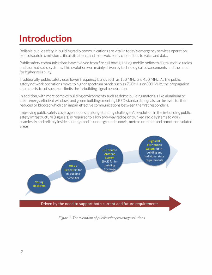
Improving public safety coverage indoors is a long-standing challenge. An evolution in the in-building public safety infrastructure (Figure 1) is required to allow two-way radios or trunked radio systems to work seamlessly and reliably inside buildings and in underground tunnels, metros or mines and remote or isolated areas.
Figure 1. The evolution of public safety coverage solutions
Off-air Repeaters for
in-building coverage
Distributed Antenna System
(DAS) for in-building
Coverage
Digital RF distribution
system for in-building and
individual state requirements
Voting Receivers
Driven by the need to support both current and future requirements

3
Current Requirements of Public Safety In-Building Coverage SystemsThe purpose of an in-building public safety system is to provide enhanced coverage when the existing macro network is not able to adequately provide the required signals. In-building public safety coverage is required by first responders to properly use their communication systems in order to do their job and execute mission-critical applications in midst of an emergency.
Coverage is required at all times and also in areas such as stairwells and backrooms, which are not commonly the prime coverage areas in commercial wireless systems. Public safety in-building systems must comply with NFPA and IFC codes, and also with NEMA 4/4X or IP66 enclosure requirements to stand up to harsh environments.
According to NFPA, critical areas, such as the fire command centers, the fire pump rooms, exit stairs, exit passageways, elevator lobbies, standpipe cabinets, sprinkler sectional valve locations, and other areas deemed critical by the authority having jurisdiction, shall be provided with 99 percent floor area radio coverage and with a minimum inbound and outbound signal strength of -95dBm. These requirements are based on current analog and P25 systems. FirstNet, an LTE based system will require different criteria.
Besides the quality of service, the availability of service is also one of the main requirements of the mission critical communication system for emergency responders. The system cannot suffer loss of service due to single point failures. Therefore, the in-building public safety distribution system should be designed and constructed with the required level of availability in mind.
Redundancy or fault tolerance is required to minimize the impact of component failure upon the operation of the whole system. Battery backup is also required under NFPA to ensure that first responders’ communication won’t be interrupted in the event of power failure.

4
Future Requirements of Public Safety In-building Coverage SystemsPublic safety requirements are evolving with improved methods in which emergency personnel communicate. Being able to transmit high-resolution imagery or real-time video footage would bring improvements in efficiencies and response time to further enhance methods to protect the public, and just as importantly, provide additional safety for first responders. For instance, those in dispatch centers who receive the real-time multimedia footage from front-line personnel would have more insight into what necessary steps should be taken to provide more timely and appropriate response and support.
Public safety agencies around the world are looking at the opportunity to leverage Long Term Evolution (LTE) technology for use in public safety communications. The evolution to broadband LTE-based public safety from the current narrowband systems such as P25 Phase I and II, and TETRA will happen gradually.
In the United States, the First Responder Network Authority, FirstNet, was signed into law on Feb 22, 2012 to build, operate and maintain the first high-speed, nationwide wireless broadband network dedicated to public safety1. The goal is to provide a single interoperable platform for emergency and daily public safety communications.
FirstNet will build a new Band Class 14 network and use LTE to augment the current P25 Phase I and II public safety communication protocols. LTE or 4G in the commercial world is based on commercial wireless standards and was chosen as it is widely accepted and deployed in the United States. This will bring the benefits of lower costs, consumer-driven economies of scale, and rapid evolution of advanced communication capabilities2.
In the United Kingdom (UK), the emergency services mobile communications program (ESMCP) will provide the next generation communication system – Emergency Services Network (ESN) for the 3 emergency services (police, fire and rescue, and ambulance) and other public safety users. ESN will provide the next generation integrated critical voice and broadband data services3.
In December 2015, the ESN user services contracts were awarded to Motorola Solutions. According to Motorola Solutions, it will provide system integration and critical functionality for the new public safety LTE-based network4. The ESN will support a network based on 4G public safety LTE technology with voice and broadband data services and it is expected to be relied on by more than 300,000 emergency and public service users are more than 300 agencies across UK4. LTE will replace the current Airwave privately owned TETRA network that covers 99% of the land mass and 98% of the population in United Kingdom5.
5
Public safety in-building coverage systems are used in situations where the signal outside the building may be optimal, but the signal inside the building is weak due to the structure of the building. In this section, we will review the options for enhancing the public safety in-building coverage. The solution chosen to be deployed will vary between applications and will depend on:
• Number of required public safety frequency bands, user groups and channels
• Required technologies: P25 Phase I & II, Tetrapol, TETRA, LTE
• Current and future requirements
• Venue size and layout
• Existing cable infrastructure
• Budget
Generally, to meet current public safety requirements, a standard channelized off-air system is sufficient. However, to satisfy both current and future requirements discussed in earlier sections, a future-proof and software-configurable in-building coverage solution is required. This will be further discussed in the section – “Digital Distributed Antenna System (DAS) – The Next Generation Approach”.
Off-air bi-directional amplifiers (BDA)Off-air Bi-Directional Amplifiers (BDA), also known as Signal Boosters, receive radio signals from a donor antenna that is pointed towards a radio tower site. The off-air BDA amplifies and retransmits the RF signal through a series of in-building antennas which radiate the amplified signal inside the building. The RF distribution network consists of coaxial cables, combiners and splitters. With passive components, the RF signal degrades with every device in the transmission chain. Therefore, sometimes additional BDAs are required on each floor to further amplify the signals (Figure 2).
BDA units were originally band-selective only, which can be easily affected by interfering signals that are either close to or within the passband bandwidth of the duplexer in the BDAs. More recently, due to both technical and legal considerations, channelized BDAs are deployed. With channelization, only the desired signals will be retransmitted. The unwanted signal interference, even in-band, can be eliminated with digital filtering, which can also protects the donor sites from unwanted uplink signal transmission.
Off-air BDAs (either band-selective or channelized) uses coaxial cables to carry the RF signals to the coverage areas. These rigid cables can be difficult to pull through the building structures. Therefore, BDAs are mainly used in small buildings under 50,000 square feet, but this is highly dependent on the interior layout.
Lastly, security cameras or other Wi-Fi appliances are also needed inside buildings to further support the first responders during mission critical situations. With off-air BDAs, a separate IP backhaul is needed to support the IP from these devices.
Options for Public Safety In-Building Coverage Systems

6
Distributed Antenna System (DAS)A Distributed Antenna Systems (DAS) receives RF signal from the base station or off-air BDA and distributes the RF signal to antennas over either coaxial cable (Passive DAS) or fiber (Active DAS). With passive DAS, coaxial cable and other passive components, splitters and couplers are used. Usually, a central headend BDA drives the passive DAS elements or leaky feeder cable (Figure 3). With passive components, the RF signal degrades with every device in the transmission chain. The antennas might have varying output power depending on the distance from the BDA. Cable losses also decrease the signal levels. Therefore, additional BDAs, referred to as Line Amplifiers, are used downstream sometimes to offset signal losses and extend the range of the passive DAS. However, adding amplifiers also adds to overall system noise.
Passive DAS can cost-effectively enhance public safety radio communication in small sized buildings with weak signal penetration from outdoor macro systems. The losses in coaxial cables, fiber, splitters and combiners are usually too large for this system to be effective in large venues.
This gives rise to the use of analog RF over fiber-optic transport, commonly referred to as Active DAS or Analog Fiber DAS (Figure 4). This is usually the preferred in-building wireless solution over passive DAS in larger facilities such as airports, hospitals, stadiums, high-rises, subway systems and multi-building campuses. Active DAS provides improved installation and maintenance benefits over Passive DAS, but still poses some design challenges including limited range, system noise, limited connectivity options (star topology) and fiber plant consumption in multi-node deployments.
Figure 2. Off-air bi-directional amplifier

7
Figure 3. Passive DistributedAntenna System
Figure 4. Active DistributedAntenna System
Regardless of passive or active DAS, Public safety RF signal sources can come from off-air repeaters, BDAs or base stations. When receiving multiple RF signal sources, RF combining is required at the headend. With passive and active DAS, passive intermodulation (PIM) is introduced at each RF combining step and PIM degrades the quality of the signal within the distribution network.
Typically, with a DAS, adjustments such as power level and optical delay compensation are difficult to make. The power levels at the antenna are based on the cable or fiber losses (distances between the head-end and remotes) and the splitting ratio of the installed splitters and couplers. Therefore, changing the power at one antenna will impact the other antennas. For example, in analog RF over fiber DAS, optical delay compensation is done by either using the same length of fiber to all remotes, or manually calculating the delay and adding delay elements to synchronize transmission from the headend. This can be especially challenging when broadband waveforms like LTE are used which has a stringent delay balance requirement particularly in Multiple Input Multiple Output, MIMO configurations.
8
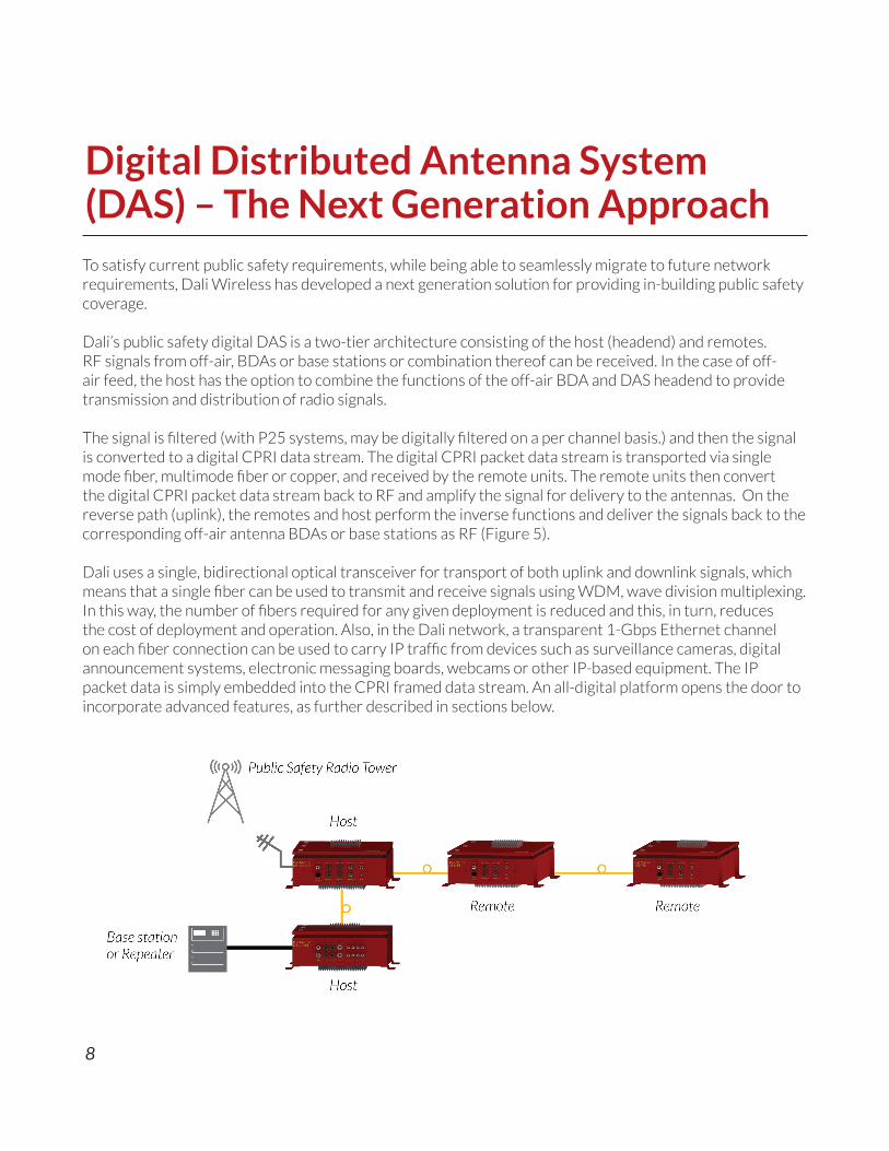
To satisfy current public safety requirements, while being able to seamlessly migrate to future network requirements, Dali Wireless has developed a next generation solution for providing in-building public safety coverage.
Dali’s public safety digital DAS is a two-tier architecture consisting of the host (headend) and remotes. RF signals from off-air, BDAs or base stations or combination thereof can be received. In the case of off-air feed, the host has the option to combine the functions of the off-air BDA and DAS headend to provide transmission and distribution of radio signals.
The signal is filtered (with P25 systems, may be digitally filtered on a per channel basis.) and then the signal is converted to a digital CPRI data stream. The digital CPRI packet data stream is transported via single mode fiber, multimode fiber or copper, and received by the remote units. The remote units then convert the digital CPRI packet data stream back to RF and amplify the signal for delivery to the antennas. On the reverse path (uplink), the remotes and host perform the inverse functions and deliver the signals back to the corresponding off-air antenna BDAs or base stations as RF (Figure 5).
Dali uses a single, bidirectional optical transceiver for transport of both uplink and downlink signals, which means that a single fiber can be used to transmit and receive signals using WDM, wave division multiplexing. In this way, the number of fibers required for any given deployment is reduced and this, in turn, reduces the cost of deployment and operation. Also, in the Dali network, a transparent 1-Gbps Ethernet channel on each fiber connection can be used to carry IP traffic from devices such as surveillance cameras, digital announcement systems, electronic messaging boards, webcams or other IP-based equipment. The IP packet data is simply embedded into the CPRI framed data stream. An all-digital platform opens the door to incorporate advanced features, as further described in sections below.
Digital Distributed Antenna System (DAS) – The Next Generation Approach
Figure 5. Digital Distributed Antenna System
9
ChannelizationTo ensure the integrity of public safety radio communications, the highest level of filtering is required – both uplink and downlink, especially the case of off-air signal pick-up and delivery. With off-air repeaters signal, Dali digital DAS uses filtering to eliminate or reduce the impact of interfering signals and reduce extraneous noise pick- up. On the uplink side, harmful effects of a high power handset located near an antenna are also eliminated. This is done by a combination of dual stage Automatic Level Control (ALC) circuit, and high performance digital filtering to provide the best possible dynamic range and in-band interference protection.
The Dali Digital DAS uses advanced digital signal processing and agile digital filtering to provide distortion free and intermodulation free radio channels. System provides agile downlink filters with selectable bandwidth. Channelization can all be set locally or remotely via the graphical user interface (GUI). With this flexibility, system integrators and public safety operators can deploy systems in selected channels and bandwidths, and then easily reconfigure via software to operate within another set of channels or bandwidths as future requirements change. This capability needs to be implemented in conjunction with analog filtering to provide maximum performance and protection from overload, and to adhere to optimal RF design practices.
Long DistanceThe ability to carry optical signals over a long distance, as far as 40 km (up to 30 dBo optical link budget) is the result of the Dali Digital DAS digital signal processing feature. It enables new deployment scenarios such as centralized headend architecture, and other indoor and underground applications, such as tunnels, metro systems and mines, without adding additional boosters and/or headend units.
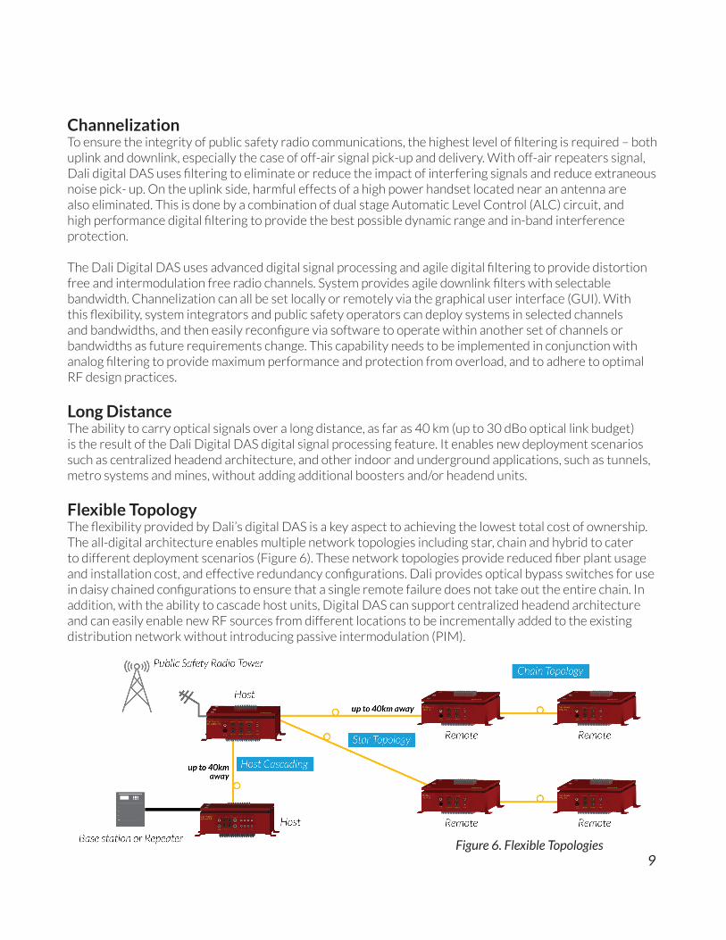
Flexible TopologyThe flexibility provided by Dali’s digital DAS is a key aspect to achieving the lowest total cost of ownership. The all-digital architecture enables multiple network topologies including star, chain and hybrid to cater to different deployment scenarios (Figure 6). These network topologies provide reduced fiber plant usage and installation cost, and effective redundancy configurations. Dali provides optical bypass switches for use in daisy chained configurations to ensure that a single remote failure does not take out the entire chain. In addition, with the ability to cascade host units, Digital DAS can support centralized headend architecture and can easily enable new RF sources from different locations to be incrementally added to the existing distribution network without introducing passive intermodulation (PIM).
Figure 6. Flexible Topologies

10
IP BackhaulA transparent 1 Gb/s Ethernet channel on each fiber connection can be used to carry IP traffic from other IP devices such as IP cameras, digital announcement systems, Wi-Fi access points, and others (Figure 7). This option is important as there is an increased use of IP cameras, GPS systems to determine the location of the alarms via IP and other non-critical applications where Wi-Fi is a reasonable alternative.
Automatic Optical Delay CompensationTraditionally, optical delay compensation is done by using the same length of fiber to all remotes, or manually calculating the delay and adding delay elements to synchronize transmission from the headend to the remotes. With an all-digital and software-configurable platform, the optical delay is measured and the compensation is calculated. Then the delay is normalized automatically across all fibers with just a click of a button to synchronize transmission from multiple simulcast antennas (Figure 8). This saves site engineers time as no additional hardware is required to fine tune delay once the in-building public safety system is installed.
Supports LTE and FirstNet TodayDali’s all-digital and software-configurable platform supports FirstNet and LTE technologies today, hence integrators and public safety operators can easily transition from P25 Phase I and II or TETRA/Tetrapol to LTE. This platform is also future ready since new waveforms/standards can be easily implemented. This is possible since the digital signal processing is conducted using Field Programmable Gate Array (FPGA) devices that enable changes or upgrades by simply uploading a new image into FPGA. Therefore, with an all-digital and software configurable solution, integrators and public safety operators only need to make the hardware investment initially, and can easily expand and upgrade their network without a major overhaul.
The technology Dali uses also includes digital delay compensation to ensure that the signals to and from each radio remote are synchronized to less than 35ns. This level of precision exceeds 3GPP LTE requirements for MIMO. Since MIMO performance is sensitive to phase synchronization or jitter and balanced power between the radio remotes, this capability is effective in implementing high-performance
Figure 7. IP Backhaul
Figure 8. Automatic Optical Delay Compensation

11
MIMO. Tight synchronization is also a prerequisite for simulcast operation, and precise simulcast is key to enabling efficient MIMO and avoiding interference between adjacent radios.
RedundancySeamless public safety communication is required at all times. The system cannot suffer loss of service due to single of point of failure; therefore, redundancy is very important to ensure that communication between the first responders does not get interrupted. With its all-digital nature, it can provide a range of redundancy features including hot-standby host, hot-standby RF modules inside the host, hot-standby remote, secondary fiber optic link, and automatic equipment failure detection and switchover.
1:1 redundancy is achieved by deploying a secondary host in hot-standby mode and the same can be accomplished at the remote site by deploying a secondary remote unit with optical and RF bypass kit. Fiber diversity can be attained by deploying a secondary fiber that runs on a different path from the host to the remote unit (Figure 9).
Another feature that is unique to Digital DAS is the automatic equipment failure detection and switchover. In the case of primary host failure, and/or primary fiber failure, the intelligent remote unit(s) will detect a loss of signal and automatically switch to the secondary optical link and standby host. In addition, Digital DAS will automatically measure and compensate for changes in delays in the fiber connected to the remotes caused by the introduction of the secondary optical link. This is important for narrowband waveforms, but will become particularly important with broadband waveforms like LTE which has a stringent delay balance requirement.
Figure 7. IP Backhaul
Figure 9. Redundancy
12
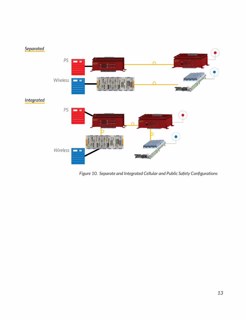
Supports Cellular + Public SafetyIn-building public safety coverage is required by first responders to properly do their job and execute mission-critical applications in midst of an emergency. Coverage is required at all times and also in areas such as stairwells and backrooms, which are not commonly the prime coverage areas in cellular systems. In addition, due to the nature of public safety, redundancy is also required to minimize the impact of component failure upon the operation of the whole system. Therefore, the design of a public safety system is significantly different than a cellular DAS deployment where capacity is the main concern.
With two very different goals and requirements, design is also very different. For example, antenna placement might be different due to the frequencies utilized in public safety and cellular environments. Not only that, cellular systems need to be planned for capacity, and often times, re-sectorization is required to accommodate the increase in traffic in a particular area. Whereas, for a public safety system, reliable coverage at all times is very important.
Due to the conflicting nature of cellular services and public safety requirements including the increased security requirement inherent in public safety installations and the different coverage and capacity requirements, public safety and commercial systems should be implemented as separate systems where budget permits.
However, it is recommended that both the public safety and cellular systems to be installed in parallel, as it will be beneficial to lay cables for both systems at the same time to reduce ceiling and riser work, thus saving cost.
With the flexible and scalable nature of Digital DAS, integrators and public safety operators can make an informed decision whether to have cellular and public safety in-building coverage as a separate system or an integrated system, while understanding the benefits and compromises of each selection. Both options are available with an all-digital solution and the decision is based on each project’s goals, requirements and design. With up to 320 MHz of aggregated bandwidth per wavelength, Dali digital platform can support both cellular and public safety frequency bands over the same fiber (Figure 10).
Data Scrambling & EncryptionSecure radio communications between first responders and public safety organizations is required. Systems should apply features counteracting eavesdropping, content tampering and content forging. Besides the encryption done by trunked radio systems, Digital DAS adds additional scrambling of the data being transmitted over the fiber link, further increasing the protection of the content if intercepted during transport.
Access to the control and management (C&M) functions are password protected and encrypted. This is achieved using HTTP Secure protocol (HTTPS), or HTTP over secure socket layer (SSL), or with transport layer security (TSL) that provides authentication and bi-direction encryption of communications between the users and the servers.
13
Figure 10. Separate and Integrated Cellular and Public Safety Configurations

14
ConclusionPublic safety agencies around the world are looking at the opportunity to leverage LTE for public safety communications, which will include data applications. FirstNet is set to bring a nationwide broadband interoperable public safety network for the first responders and other emergency personnel in United States. In the United Kingdom, ESN will provide the next generation integrated critical voice and broadband data services.
The evolution to broadband LTE-based public safety from the current narrowband systems such as P25 Phase I and II, and TETRA will happen gradually. Therefore, a flexible, future-proof and reliable solution is required to satisfy both the current requirements and future, next-gen public safety in-building requirements.
Dali public safety digital DAS is a next generation solution that transcends the traditional RF-over-fiber analog DAS or Bi-Directional Amplifiers (BDAs). With its patented digital signal processing and software re-configurability, Matrix PS enables a unified broadband/narrowband communications infrastructure supporting the interoperability of current P25/Tetra systems and broadband systems like LTE and Wi-Fi.
With such a flexible system, Dali enables public safety operators and integrators to meet today’s voice and data requirements while providing them with a seamless migration path to address the evolving public safety broadband requirements including LTE, FirstNet and ESN.

15
1. FirstNet - http://www.firstnet.gov/about2. FirstNet - http://www.firstnet.gov/network 3. Emergency Services Network (ESN) - https://www.gov.uk/government/publications/the-emergency-
services-mobile-communications-programme/emergency-services-network#emergency-services-network-timeline
4. Motorola Solutions chosen for UK’s next generation public safety communications system - https://newsroom.motorolasolutions.com/news/motorola-solutions-chosen-for-uks-next-generation-public-safety-communications-system.htm
5. Urgent Communications: UK seeks to replace TETRA with LTE as early as 2016 - http://urgentcomm.com/tetra/uk-seeks-replace-tetra-lte-early-2016
References

About Dali WirelessFounded in 2006, Dali Wireless is a global provider of the advanced all-digital RF Router® that transcends traditional Distributed Antenna Systems (DAS) to deliver more data throughput and value at a lowest Total Cost of Ownership (TCO). Dali’s patented all-digital RF distribution system enhances and extends the coverage and capacity of commercial and public safety networks. With its digital nature and software-configurability, it is purposed-built to meet today’s voice and data requirements while offering a clear migration path to address the evolving broadband LTE requirements in public safety, and a software-defined RAN in commercial networks.
www.daliwireless..com
Dali Wireless, Inc. 535 Middlefield Road, Suite 280Menlo Park, CA, 94025 USA
Dali Wireless (Canada), Inc. 8618 Commerce CourtBurnaby, BC, V5A 4N6 Canada
Dali Wireless (Hong Kong) Co., Inc. Suite 3911, 39/F., Jardine House, 1 Connaught Place Central, Hong Kong
Web: www.daliwireless.comToll Free: 1-855-250-5082International: +1-604-420-7760Email: [email protected]
Dali Wireless and RF ROUTER are registered trademarks. Dali Matrix, hd30, hd37 and hd43 are trademarks of Dali Wireless, Inc. Any product and company names listed are trademarks or trademarks of their respective companies. Specifications are subject to changewithout notice. The information contained herein does not constitute part of any order or contract.