Intro to ECE Final - Complete Formula Sheet
3
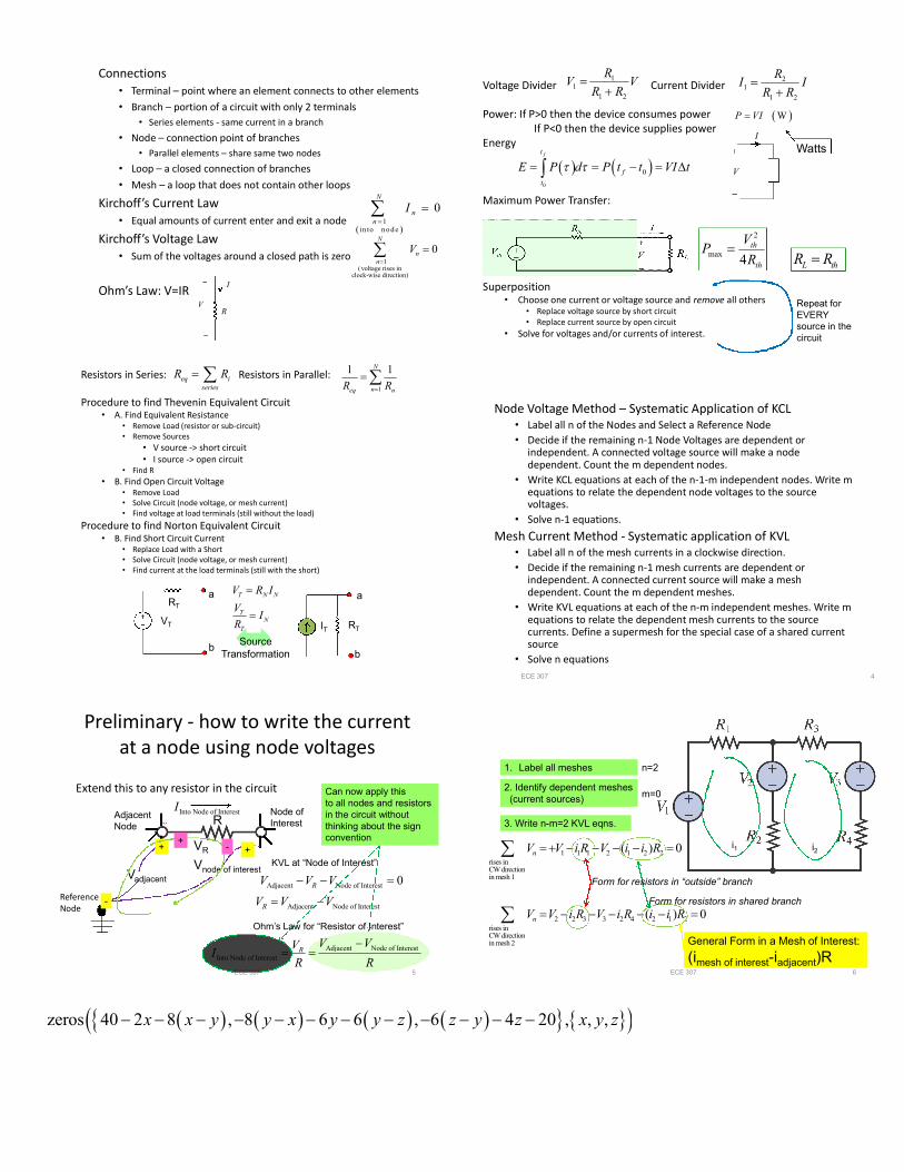
Connections • Terminal – point where an element connects to other elements • Branch – portion of a circuit with only 2 terminals • Series elements - same current in a branch • Node – connection point of branches • Parallel elements – share same two nodes • Loop – a closed connection of branches • Mesh – a loop that does not contain other loops Kirchoff’s Current Law • Equal amounts of current enter and exit a node Kirchoff’s Voltage Law • Sum of the voltages around a closed path is zero Ohm’s Law: V=IR 1 into node 0 N n n I 1 ( voltage rises in clock-wise direction) 0 N n n V R V I Voltage Divider Current Divider Power: If P>0 then the device consumes power If P<0 then the device supplies power Energy Maximum Power Transfer: Superposition • Choose one current or voltage source and remove all others • Replace voltage source by short circuit • Replace current source by open circuit • Solve for voltages and/or currents of interest. W P VI Watts V I 0 0 f t f t E P d Pt t VI t 1 1 1 2 R V V R R 2 1 1 2 R I I R R L th R R 2 max 4 th th V P R Repeat for EVERY source in the circuit Resistors in Series: Resistors in Parallel: Procedure to find Thevenin Equivalent Circuit • A. Find Equivalent Resistance • Remove Load (resistor or sub-circuit) • Remove Sources • V source -> short circuit • I source -> open circuit • Find R • B. Find Open Circuit Voltage • Remove Load • Solve Circuit (node voltage, or mesh current) • Find voltage at load terminals (still without the load) Procedure to find Norton Equivalent Circuit • B. Find Short Circuit Current • Replace Load with a Short • Solve Circuit (node voltage, or mesh current) • Find current at the load terminals (still with the short) eq i series R R 1 1 1 N n eq n R R a b R T a b R T V T I T Source Transformation T N N T N T V RI V I R Node Voltage Method – Systematic Application of KCL • Label all n of the Nodes and Select a Reference Node • Decide if the remaining n-1 Node Voltages are dependent or independent. A connected voltage source will make a node dependent. Count the m dependent nodes. • Write KCL equations at each of the n-1-m independent nodes. Write m equations to relate the dependent node voltages to the source voltages. • Solve n-1 equations. Mesh Current Method - Systematic application of KVL • Label all n of the mesh currents in a clockwise direction. • Decide if the remaining n-1 mesh currents are dependent or independent. A connected current source will make a mesh dependent. Count the m dependent meshes. • Write KVL equations at each of the n-m independent meshes. Write m equations to relate the dependent mesh currents to the source currents. Define a supermesh for the special case of a shared current source • Solve n equations ECE 307 4 Preliminary - how to write the current at a node using node voltages Extend this to any resistor in the circuit ECE 307 5 Adjacent Node of Interest Adjacent Node of Interest 0 R R V V V V V V Reference Node R + - Node of Interest V node of interest V adjacent Adjacent Node KVL at “Node of Interest” + Can now apply this to all nodes and resistors in the circuit without thinking about the sign convention + - V R Adjacent Node of Interest Into Node of Interest R V V V I R R Ohm’s Law for “Resistor of Interest” Into Node of Interest I ECE 307 6 1. Label all meshes 2. Identify dependent meshes (current sources) 3. Write n-m=2 KVL eqns. n=2 m=0 1 1 1 2 1 2 2 rises in CW direction in mesh 1 2 2 3 3 2 4 2 1 2 rises in CW direction in mesh 2 ( ) 0 ( ) 0 n n V V iR V i i R V V iR V iR i iR Form for resistors in shared branch Form for resistors in “outside” branch General Form in a Mesh of Interest: (i mesh of interest -i adjacent )R i 1 i 2 zeros 40 2 8 , 8 6 6 , 6 4 20 , , , x x y y x y y z z y z xyz
-
Upload
littleredpoppies -
Category
Documents
-
view
41 -
download
0
description
Formula sheet and basics of electrical engineering/circuits.
Transcript of Intro to ECE Final - Complete Formula Sheet
Connections• Terminal – point where an element connects to other elements
• Branch – portion of a circuit with only 2 terminals
• Series elements - same current in a branch
• Node – connection point of branches
• Parallel elements – share same two nodes
• Loop – a closed connection of branches
• Mesh – a loop that does not contain other loops
Kirchoff’s Current Law• Equal amounts of current enter and exit a node
Kirchoff’s Voltage Law• Sum of the voltages around a closed path is zero
Ohm’s Law: V=IR
1
in to n o d e
0N
nn
I
1(voltage rises in
clock-wise direction)
0N
nn
V
RV
I
Voltage Divider Current Divider
Power: If P>0 then the device consumes powerIf P<0 then the device supplies power
Energy
Maximum Power Transfer:
Superposition• Choose one current or voltage source and remove all others
• Replace voltage source by short circuit• Replace current source by open circuit
• Solve for voltages and/or currents of interest.
WP VI
Watts
V
I
0
0
ft
f
t
E P d P t t VI t
11
1 2
RV V
R R
2
1
1 2
RI I
R R
L thR R
2
max4
th
th
VP
R
Repeat forEVERYsource in thecircuit
Resistors in Series: Resistors in Parallel:
Procedure to find Thevenin Equivalent Circuit• A. Find Equivalent Resistance
• Remove Load (resistor or sub-circuit)• Remove Sources
• V source -> short circuit• I source -> open circuit
• Find R
• B. Find Open Circuit Voltage• Remove Load• Solve Circuit (node voltage, or mesh current)• Find voltage at load terminals (still without the load)
Procedure to find Norton Equivalent Circuit• B. Find Short Circuit Current
• Replace Load with a Short• Solve Circuit (node voltage, or mesh current)• Find current at the load terminals (still with the short)
eq iseries
R R 1
1 1N
neq nR R
a
b
RT
a
b
RTVT IT
SourceTransformation
T N N
TN
T
V R I
VI
R
Node Voltage Method – Systematic Application of KCL• Label all n of the Nodes and Select a Reference Node
• Decide if the remaining n-1 Node Voltages are dependent orindependent. A connected voltage source will make a nodedependent. Count the m dependent nodes.
• Write KCL equations at each of the n-1-m independent nodes. Write mequations to relate the dependent node voltages to the sourcevoltages.
• Solve n-1 equations.
Mesh Current Method - Systematic application of KVL• Label all n of the mesh currents in a clockwise direction.
• Decide if the remaining n-1 mesh currents are dependent orindependent. A connected current source will make a meshdependent. Count the m dependent meshes.
• Write KVL equations at each of the n-m independent meshes. Write mequations to relate the dependent mesh currents to the sourcecurrents. Define a supermesh for the special case of a shared currentsource
• Solve n equations
ECE 307 4
Preliminary - how to write the currentat a node using node voltages
Extend this to any resistor in the circuit
ECE 307 5
Adjacent Node of Interest
Adjacent Node of Interest
0R
R
V V V
V V V
ReferenceNode
R
+
-
Node ofInterest
Vnode of interestVadjacent
AdjacentNode
KVL at “Node of Interest”
+
Can now apply thisto all nodes and resistorsin the circuit withoutthinking about the signconvention+
-VR
Adjacent Node of Interest
Into Node of InterestR
V VVI
R R
Ohm’s Law for “Resistor of Interest”
Into Node of InterestI
ECE 307 6
1. Label all meshes
2. Identify dependent meshes(current sources)
3. Write n-m=2 KVL eqns.
n=2
m=0
1 1 1 2 1 2 2rises inCW directionin mesh 1
2 2 3 3 2 4 2 1 2rises inCW directionin mesh 2
( ) 0
( ) 0
n
n
V V i R V i i R
V V i R V i R i i R
Form for resistors in shared branch
Form for resistors in “outside” branch
General Form in a Mesh of Interest:
(imesh of interest-iadjacent)R
i1 i2
zeros 40 2 8 , 8 6 6 , 6 4 20 , , ,x x y y x y y z z y z x y z

ECE 307 7
( )( ) C
C
dv ti t C
dt
( )( ) L
L
di tv t L
dt
1
1 1N
iEQ iL L
1
N
EQ ii
L L
1
1 1N
iEQ iC C
1
N
EQ ii
C C
Series Connected: Parallel Connected:
cosx t A t Sinusoids 1 2
Hertz or Hz 2 rad/s secondsf f TT T
supplied to device stored or dissipated 0 0
t t
p t v t i t W t p t dt v t i t dt
2
00
tt
dissipated
v t v tW v t dt dt
R R
2 2 2stored
00
1 1if 0 0
2 2
tt di t
W L i t dt Li t Li t idt
2 2 2stored 0
0
1 1if (0) 0
2 2
tt dv t
W v t C dt Cv t Cv t vdt
2 maxmax0
10.707
2
T
rms
VV v t dt V
T max cosv t V t
Complex numberscos sinje j
Euler’s Identity
Rectangular Form x A jB
180 180 orjx Ce C Polar Form
2 2 1tan /C A B B A cos sinA C B C
1j
Capacitors and Inductors
RMS
ECE 307 8
( ) cos sinjj Ae A jA A V( ) cos( )v t A t Phasor Transformation
Impedance
)()()( jIjZjV ( )
( )( )
V jZ j
I j
00 Re jRZ R R
290j
LZ j L L Le
21 1 1
90j
CZ ej C C C
1
N
EQ ii
Z Z
Series Impedances
1
1 1N
iEQ iZ Z
Parallel Impedances
Transform circuit to frequency domain thenproceed similar to DC Analysis
Series and Parallel Reduction forImpedancesMesh Current Method for AC circuitsNode Voltage Method for AC circuitsThevenin Equivalent for AC circuitsSuperposition for AC circuits
Transform back to find time domain signal
Frequency Domain or Phasor Domain Circuit Analysis
2 2rms rms
V IV IV I
2
22
1cos cos cos cos
2 2
1cos cos
2
av
VVI VP
Z Z
Z I Z
V I
I
jjZ Z e R jX
j
V
I
0
1cos
2
T
av
VIP p t dt
T
2
1
f
Tf
cosavP
pfV I
0 1pf
*S VI
cos sin
av
S V I jV I
P jQ
cos
sin
avP V I
Q V I
|S| - apparent power
- units volt-amperes (VA)
Re
Im
s Q - reactive power- volt-amperes reactive (VAR)
Pav - real power (absorbed by load resistance)- watts (W)
2 2
avP R Q X I I
* 2*/ /
av
S Z Z
P jQ
V V V
2
2
1if
1if
avZ R PR
Z jX QX
V
V
Complex Power Equations
Power factor correction
2
2
sin
cosavP V I I R
Q V I I X
load needingpf correction
Shunt reactanceto give pf correction
avP
2A AI X Q
2B BI X Q
S
Power factor Triangle
Condition for correction:
Make: B AQ Q
1 1if ifA B A BX L X X X L
C C
avS P
1V 2V
1I2I
1 2:n n
1 : Nor2
1
nN
n
12 1 2
IV NV I
N
* * *21 2 21 21 2S N S
N
VV I I V I
SV
SZ
LZ
* or andL S L S L SZ Z R R X X
2
max 4
S
av
S
PR
V
SV
SZ
LZ
a
b
1V
2V
SZ
1 2:n n2
1ab LZ Z
N
* *
2 2 2
1 L LS S S ab L
R XZ R jX Z Z j
N N N
Max Power
2 2andL S L SR N R X N X
inductor
1capacitor
S
L
X
C
Max Power to load
Power thru Ideal Transformer
Ideal Transformer Equations
2
2
10182
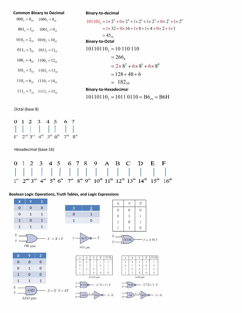
Octal (base 8)
Hexadecimal (base 16)
2 10000 0
2 10001 1
2 10010 2
2 10011 3
2 10100 4
2 10101 5
2 10110 6
2 10111 7
2 101000 8
2 101001 9
2 101010 10
2 101011 11
2 101100 12
2 101101 13
2 101110 14
2 101111 15
Common Binary to Decimal
101101 1 0 1 1 0 1
10110110 10 110 110
Binary
Binary
10110110 1011 0110 B6 B6H
Binary
Boolean Logic Operations, Truth Tables, and Logic Expressions
X Y Z
0 0 0
0 1 1
1 0 1
1 1 1
X Y Z
0 0 0
0 1 0
1 0 0
1 1 1
X Y
X Y XY
X X
0 1
1 0
5 4 3 2 1 02
10
2 2 2 2101101 1 0 1 1 0 1
1 0 1 1
2 2
32 16 8 4 2 1
45
0 1
2
8
2 1 0
10
10110110 10 110 110
266
8 8 8
128 48
2
1
6
5
6
6
2
Binary-to-decimal
Binary-to-Octal
2 1610110110 1011 0110 B6 B6H
Binary-to-Hexadecimal
Boolean Logic Operations, Truth Tables, and Logic Expressions
X
1
0
18210
5 4 3 2 1 0101101 1 0 1 1 0 12 2
32 16 8 4 2 1