Intraoperative radiation therapy using mobile electron linear accelerators: Report … ·...
14
Intraoperative radiation therapy using mobile electron linear accelerators: Report of AAPM Radiation Therapy Committee Task Group No. 72 A. Sam Beddar a Department of Radiation Physics, Division of Radiation Oncology, Unit 94, The University of Texas M.D. Anderson Cancer Center, Houston, Texas 77030 Peter J. Biggs Department of Radiation Oncology, Massachusetts General Hospital, Boston, Massachusetts 02114 Sha Chang Department of Radiation Oncology, University of North Carolina School of Medicine, Chapel Hill, North Carolina 27599 Gary A. Ezzell Department of Radiation Oncology, Mayo Clinic Scottsdale, Scottsdale, Arizona 85259 Bruce A. Faddegon Department of Radiation Oncology, University of California San Francisco, San Francisco, California 94143 Frank W. Hensley Department of Radiation Oncology, University of Heidelberg, 69120 Heidelberg, Germany Michael D. Mills Department of Radiation Oncology, James Graham Brown Cancer Center, Louisville, Kentucky 40202 Received 16 September 2005; revised 10 March 2006; accepted for publication 15 March 2006; published 28 April 2006 Intraoperative radiation therapy IORT has been customarily performed either in a shielded oper- ating suite located in the operating room OR or in a shielded treatment room located within the Department of Radiation Oncology. In both cases, this cancer treatment modality uses stationary linear accelerators. With the development of new technology, mobile linear accelerators have re- cently become available for IORT. Mobility offers flexibility in treatment location and is leading to a renewed interest in IORT. These mobile accelerator units, which can be transported any day of use to almost any location within a hospital setting, are assembled in a nondedicated environment and used to deliver IORT. Numerous aspects of the design of these new units differ from that of conventional linear accelerators. The scope of this Task Group TG-72 will focus on items that particularly apply to mobile IORT electron systems. More specifically, the charges to this Task Group are to i identify the key differences between stationary and mobile electron linear accel- erators used for IORT, ii describe and recommend the implementation of an IORT program within the OR environment, iii present and discuss radiation protection issues and consequences of working within a nondedicated radiotherapy environment, iv describe and recommend the accep- tance and machine commissioning of items that are specific to mobile electron linear accelerators, and v design and recommend an efficient quality assurance program for mobile systems. © 2006 American Association of Physicists in Medicine. DOI: 10.1118/1.2194447 TABLE OF CONTENTS I. INTRODUCTION............................ 1477 II. IORT USING MOBILE VERSUS STATIONARY LINEAR ACCELERATORS................... 1477 III. IMPLEMENTATION OFAN IORT PROGRAM WITHIN AN OPERATING ROOM ENVIRONMENT........................... 1478 IV. RADIATION PROTECTION.................. 1478 A. Regulatory considerations................ 1479 B. Radiation site plan...................... 1479 1. Treatment operating rooms............. 1479 2. Commissioning and annual quality assurance location.................... 1479 C. Radiation survey........................ 1479 D. Exposure rate measurements.............. 1479 V. ACCEPTANCE TESTING AND COMMISSIONING.......................... 1480 A. Acceptance testing measurements.......... 1480 B. Commissioning and dose measurements..... 1482 VI. RECOMMENDED QUALITY ASSURANCE.... 1484 A. Previous quality assurance recommendations for medical linear accelerators............. 1484 B. Quality assurance for mobile electron accelerators............................ 1484 VII. CLINICAL ASPECTS OF IORT TREATMENT DELIVERY: DOSE SPECIFICATION......... 1486 VIII. RECOMMENDATIONS FOR FUTURE CONSIDERATIONS....................... 1487 1476 1476 Med. Phys. 33 „5…, May 2006 0094-2405/2006/33„5…/1476/14/$23.00 © 2006 Am. Assoc. Phys. Med.
-
Upload
truongcong -
Category
Documents
-
view
216 -
download
0
Transcript of Intraoperative radiation therapy using mobile electron linear accelerators: Report … ·...
Intraoperative radiation therapy using mobile electron linear accelerators:Report of AAPM Radiation Therapy Committee Task Group No. 72
A. Sam Beddara�
Department of Radiation Physics, Division of Radiation Oncology, Unit 94, The University of Texas M.D.Anderson Cancer Center, Houston, Texas 77030
Peter J. BiggsDepartment of Radiation Oncology, Massachusetts General Hospital, Boston, Massachusetts 02114
Sha ChangDepartment of Radiation Oncology, University of North Carolina School of Medicine, Chapel Hill,North Carolina 27599
Gary A. EzzellDepartment of Radiation Oncology, Mayo Clinic Scottsdale, Scottsdale, Arizona 85259
Bruce A. FaddegonDepartment of Radiation Oncology, University of California San Francisco, San Francisco,California 94143
Frank W. HensleyDepartment of Radiation Oncology, University of Heidelberg, 69120 Heidelberg, Germany
Michael D. MillsDepartment of Radiation Oncology, James Graham Brown Cancer Center, Louisville, Kentucky 40202
�Received 16 September 2005; revised 10 March 2006; accepted for publication 15 March 2006;published 28 April 2006�
Intraoperative radiation therapy �IORT� has been customarily performed either in a shielded oper-ating suite located in the operating room �OR� or in a shielded treatment room located within theDepartment of Radiation Oncology. In both cases, this cancer treatment modality uses stationarylinear accelerators. With the development of new technology, mobile linear accelerators have re-cently become available for IORT. Mobility offers flexibility in treatment location and is leading toa renewed interest in IORT. These mobile accelerator units, which can be transported any day of useto almost any location within a hospital setting, are assembled in a nondedicated environment andused to deliver IORT. Numerous aspects of the design of these new units differ from that ofconventional linear accelerators. The scope of this Task Group �TG-72� will focus on items thatparticularly apply to mobile IORT electron systems. More specifically, the charges to this TaskGroup are to �i� identify the key differences between stationary and mobile electron linear accel-erators used for IORT, �ii� describe and recommend the implementation of an IORT program withinthe OR environment, �iii� present and discuss radiation protection issues and consequences ofworking within a nondedicated radiotherapy environment, �iv� describe and recommend the accep-tance and machine commissioning of items that are specific to mobile electron linear accelerators,and �v� design and recommend an efficient quality assurance program for mobile systems. © 2006American Association of Physicists in Medicine. �DOI: 10.1118/1.2194447�
TABLE OF CONTENTS
I. INTRODUCTION. . . . . . . . . . . . . . . . . . . . . . . . . . . . 1477II. IORT USING MOBILE VERSUS STATIONARY
LINEAR ACCELERATORS. . . . . . . . . . . . . . . . . . . 1477III. IMPLEMENTATION OF AN IORT PROGRAM
WITHIN AN OPERATING ROOMENVIRONMENT. . . . . . . . . . . . . . . . . . . . . . . . . . . 1478
IV. RADIATION PROTECTION. . . . . . . . . . . . . . . . . . 1478A. Regulatory considerations. . . . . . . . . . . . . . . . 1479B. Radiation site plan. . . . . . . . . . . . . . . . . . . . . . 1479
1. Treatment operating rooms. . . . . . . . . . . . . 14792. Commissioning and annual quality
assurance location. . . . . . . . . . . . . . . . . . . . 1479
1476 Med. Phys. 33 „5…, May 2006 0094-2405/2006/33„5…/1
C. Radiation survey. . . . . . . . . . . . . . . . . . . . . . . . 1479D. Exposure rate measurements. . . . . . . . . . . . . . 1479
V. ACCEPTANCE TESTING ANDCOMMISSIONING. . . . . . . . . . . . . . . . . . . . . . . . . . 1480
A. Acceptance testing measurements. . . . . . . . . . 1480B. Commissioning and dose measurements. . . . . 1482
VI. RECOMMENDED QUALITY ASSURANCE. . . . 1484A. Previous quality assurance recommendations
for medical linear accelerators. . . . . . . . . . . . . 1484B. Quality assurance for mobile electron
accelerators. . . . . . . . . . . . . . . . . . . . . . . . . . . . 1484VII. CLINICAL ASPECTS OF IORT TREATMENT
DELIVERY: DOSE SPECIFICATION. . . . . . . . . 1486VIII. RECOMMENDATIONS FOR FUTURE
CONSIDERATIONS. . . . . . . . . . . . . . . . . . . . . . . 1487
1476476/14/$23.00 © 2006 Am. Assoc. Phys. Med.
1477 Beddar et al.: Task Group No. 72 1477
I. INTRODUCTION
Intraoperative radiation therapy �IORT� has had a long his-tory in cancer management. The earliest concept of IORT asa cancer treatment modality was introduced in 1909, whenCarl Beck attempted to treat patients with gastric and coloncancer.1 Beck irradiated seven patients with inoperable gas-tric cancer and one patient with colon cancer by pulling thetumor into the abdominal wound and irradiating it. The treat-ments were unsuccessful due to low beam energies, low doserates, and limited radiotherapy equipment, thus hinderingthese early efforts. It was not until 1984 in Japan,2 that IORTtreatment techniques using megavoltage radiation producedby a linear accelerator �linac� became successful. Therefore,modern IORT practice dates from the work of Abe et al.3 andAbe and Takahashi4 in Japan published in the early 1970sand 1980s. The practice of IORT was started in the UnitedStates in the late 1970s by Goldson at Howard University,5
Gunderson et al. at Massachusetts General Hospital,6 andTepper and Sindelar7 and Fraas et al.8 at the National CancerInstitute.
Initially, IORT flourished in both the academic and com-munity hospital setting. In 1992, Coia and Hanks.9 reportedon a pattern-of-care study that indicated that of 1293 radia-tion oncology facilities in the United States, 108 reporteddoing IORT, and 29 of those had two or more residents. Withapproximately 90 residency training programs in existence atthat time, that means that roughly one third were performingIORT. Fewer than 30 centers are now performing IORT. Thereasons for this decline in interest are twofold. First, estab-lishing the usefulness of IORT as adjunct therapy has beendifficult. Single-institution experiences have suggested theusefulness of IORT for primary T4 and recurrent rectalcancer,10–13 retroperitoneal sarcoma,14,15 pancreaticcancer,16–18 and selected recurrent gynecologic19–21 and geni-tourinary malignancies.22–25 Because of the difficulty in ac-cruing large numbers of patients for these disease sites, it isunlikely that phase III studies evaluating the utility of IORTas a definitive therapeutic modality could be performed un-less this were done on an international basis. The exceptioncould be in the area of breast cancer, where significant num-bers of patients have already been treated in Europe. Second,the majority of centers use their conventional linacs to per-form IORT. In this case, the anesthetized patient must bemoved to a sanitized treatment room, accompanied by oper-ating room �OR� personnel. This is technically difficult andrelatively inefficient, with the linac often unavailable forconventional treatment for a considerable time for roompreparation and waiting for the patient. The uphill battlefaced by proponents of IORT is the high cost of a dedicatedfacility in the OR. A dedicated linac in an OR is no longer acost-effective option for any hospital when the costs of themachine and radiation shielding are included.
The entry into the field of IORT of mobile linacs that canbe used in existing ORs with reduced shielding requirementsmakes the cost and logistics of setting up an IORT programmuch easier and therefore provides a stimulus to the field.Two manufacturers of mobile linacs are Intraop Medical In-
Medical Physics, Vol. 33, No. 5, May 2006
corporated of Santa Clara, California, which manufacturesthe Mobetron, and Hitesys of Aprilia, Italy, which manufac-tures the Novac7. Currently, 26 mobile units are installed inthe United States and Europe.26 Thus, there has been a resur-gence of interest in IORT in recent years.
By now, many of the new mobile units have been in op-eration for several years and we have gained important ex-perience in mobile IORT technology. Although there aremany similarities between IORT treatments via stationaryunits and mobile units, several important considerations areunique to mobile units. This installed base of mobile linacsand the degree of clinical activity that is currently being car-ried out motivates a review of all the physics proceduresassociated with operating these units in a clinical setting.
The purpose of this Task Group �TG-72� is to providesufficient information for a physicist to contribute to thephysical aspects of the planning process, such as room selec-tion, estimation of required radiation shielding, and adequateselection of treatment equipment for the prospective IORTprogram, and to perform the required acceptance tests andcommissioning to bring one of these units into clinical op-eration. There are significant differences between the twomobile systems in their mechanical design, accelerationmethodology, dosimetry, and docking. Both the Mobetronand Novac7 are approved by the U.S. Food and Drug Ad-ministration �FDA�, although there are no Novac7 units cur-rently operating in the United States. This report comple-ments the work of previous Task Groups on IORT27 andelectron-beam dosimetry28,29 Due to space considerations,we have abbreviated certain sections of the published versionof this report. The full unabridged version, with detailed il-lustrations, is available electronically.30
This Task Group has been careful to follow current�AAPM� practice in the use of prescriptive injunctions suchas “must,” “shall,” and “should.” Imperatives such as “must”or “shall” apply to matters of compliance with law or regu-lation. “Recommendations” are applied to procedures thatthe Task Group deems important to follow, although a physi-cist may always choose alternatives after careful consider-ation. “Should” is used to identify suggested procedures toaddress significant QA issues for which a variety of ap-proaches are reasonable.
II. IORT USING MOBILE VERSUS STATIONARYLINEAR ACCELERATORS
Stationary and mobile linacs for electron beam IORT havemany similarities. Both make use of shallow-penetrating ra-diation. Applicators are used to confine the beam to the vol-ume of interest within the surgical area. Treatment is per-formed under sterile conditions with the patient anesthetized.Radiation is delivered in a large single fraction. Multiplefields may be used to treat different areas, treat larger fields,or conform better to the target volume. Beam modifiers in-clude bolus, placed at the end of the applicator or on thepatient surface, to increase surface dose �with reduced beampenetration�, and absorbers such as lead, for shielding critical
1478 Beddar et al.: Task Group No. 72 1478
structures or field matching.31–33 A typical IORT treatmentusing a mobile unit has been described by Domanovicet al.34 in detail in a case study in which IORT was used ona patient with sigmoid carcinoma.
This report concerns differences in IORT with mobilelinacs. Some differences apply to any linac �either mobile orstationary� in a dedicated OR. Mobile units and dedicatedstationary units both permit treatment in a sterile OR. Specialtreatment accessories are required for both units, including acouch �surgical bed� to facilitate patient setup. A primaryconcern is radiation protection during treatment and dailyQA. Mobile IORT units are designed primarily for use in anunshielded OR; therefore, exposure limits typically restricttheir use to the treatment of a small number of patients perweek plus the required daily QA and warmup. To preventexcess exposure in adjacent rooms, especially on the floorbelow, the maximum beam energy is limited to 10–12 MeV,limiting target coverage to a depth of a few centimeters. Abeam stopper is incorporated in some designs, which mayinterfere with patient setup. In addition to an unshielded OR,one must also plan for a facility for dosimetry and mainte-nance �which can be the storage room� providing sufficientstructural shielding for commissioning, extended dosimetry�e.g., annual calibrations or experiments�, and maintenanceand adjustment contingencies. Some users have reduced thisneed by performing preadjustment and commissioning at themanufacturers’ facilities.
The application-specific design of mobile units can lead toadvantages over conventional units adapted to IORT. For ex-ample, electron beams could well have flatter beam profilesthan conventional linacs, and the range of motion of thetreatment head gives more flexibility in setting up the pa-tient. On the other hand, limitations on these units are im-posed by practical concerns of storage, transport, treatmentsetup, and radiation protection.
Details that differ for mobile units in program implemen-tation, including selection of the rooms required for the dif-ferent procedures �commissioning, treatment, and storage�,are dealt with in Sec. III. Radiation protection issues, arisingfrom the higher leakage and scatter in an unshielded OR, arepresented in Sec. IV. Differences in commissioning, includ-ing output calibration, are discussed in Sec. V.
III. IMPLEMENTATION OF AN IORT PROGRAMWITHIN AN OPERATING ROOM ENVIRONMENT
A successful IORT program within an OR environmentrequires careful planning, involving coordination of taskswith timely and efficient communication among several de-partments. These departments generally include operativeservices �usually referred to as the OR�, radiation oncology,surgery, anesthesiology, and engineering. Depending on theinstitution, the engineering support personnel may be part ofthe radiation oncology department. The IORT team and therole of each member of this team have been clearly definedby Task Group 48 �Ref. 27� and therefore will not be dealtwith in this report. Other support personnel,27 such as house-
Medical Physics, Vol. 33, No. 5, May 2006
keeping, security staff, transport personnel, and elevator op-erators, will not be needed because the unit will be in the ORwhere all IORT treatments will be delivered. Each depart-ment will have a significant role in the implementation ofsuch a multidisciplinary program. Consequently, a team ap-proach should be embraced from the beginning.
Implementation of an IORT program using a mobile unit35
in the OR includes staff preparation, documentation of spe-cialized procedures, and selection of the OR�s� and surgicalbed�s�.
The following steps will facilitate smooth and efficientimplementation of a mobile IORT program:
�1� Interdepartmental meetings early in the planning phase,involving all relevant departments.
�2� A site visit to an institution performing IORT using amobile system.
�3� A written proposal for program implementation, tailoredto the institution.
�4� Development of written procedures.�5� Selection of the OR�s�, storage room and dosimetry fa-
cility.�6� Selection of the surgical bed�s�.�7� Education of staff involved in the IORT procedure and
OR staff peripheral to the program.�8� Scheduled training in the OR.�9� One or more “dry runs” before the first IORT procedure.
At the beginning of such a program, we believe it is im-portant to have all members of the IORT team involved in allof the initial procedures so they can go through the learningprocess rapidly, implement the improved methods efficiently,and reach optimum performance of IORT. The training of therest of the OR staff should follow once the initial IORT teamreaches an acceptable level of confidence. A complete dis-cussion of these points is provided in the full electronicreport.30
IV. RADIATION PROTECTION
Mobile electron linacs are meant to be placed in existingOR suites that have been constructed with no special shield-ing requirements. These systems are designed with the con-cept of being utilized to deliver radiation in nonshielded ORrooms and are provided with a beam stopper.30 The beamstopper for certain mobile IORT units is designed to track themovement of the gantry in all directions so that it will alwaysintercept the primary beam, whereas other beam stoppersmust be manually positioned. Radiation leakage resultsmostly from photon leakage, scatter, and x-ray contaminationfrom the electron beams. The electron scatter produced in theOR has a limited range, and most conventional walls aresufficient to stop the electron scatter produced in the OR.36
Therefore, radiation safety assessments for these mobile sys-tems consist of performing radiation surveys around the ORsthat are intended to be used for IORT and limiting the num-ber of IORT cases that can be performed in any given OR sothat the maximum exposure limits are not exceeded.
1479 Beddar et al.: Task Group No. 72 1479
A. Regulatory considerations
Limits for radiation exposure of personnel are usuallyregulated by national or state government agencies. In theUnited States, the National Council on Radiation Protectionand Measurements.37 and the federal government promulgatestandards.38,39 In addition, standards may vary between coun-tries or states and may change with time. This Task Group�TG-72� believes the following to be absolute requirements:
�1� The most current exposure levels applicable to the geo-graphic location �country or state� of the mobile accel-erator installation shall be adopted.
�2� The site plan must be approved by the appropriate regu-latory agency before delivery of the unit takes place.
�3� A radiation survey must be performed for every ORwhere the unit will be used and for any other roomwhere the unit could be used �e.g., the dosimetry room�.
�4� The survey must be performed for the highest electronenergy, the largest applicator, and for every anticipatedand possible clinical configuration of the unit.
�5� Electrical requirements should be evaluated for the ORsselected for IORT, the storage area, and any other roomwhere the unit could be used.
�6� Floor load capacities should be evaluated for the roomsselected for IORT, the storage area, any other roomwhere the unit could be used, and all possible transpor-tation routes that could be used.
�7� Exposures accrued by personnel must be evaluated ac-cording to a radiation safety Quality ManagementProgram.
B. Radiation site plan
1. Treatment operating rooms
The manufacturer will ordinarily provide a three-dimensional radiation leakage and scatter exposure profilefor the IORT unit. If the unit is capable of a range of mo-tions, several profiles will be required to complete the siteplan properly. The anticipated workload of each mode andenergy will figure into the site plan. This workload, calcu-lated for ORs, should include the MUs for machine warm-upand daily QA but should not include the workload for com-missioning and annual QA measurements �see the followingsection�. Mills et al.40 calculated typical workload limits forexisting ORs using the Mobetron system and found that it ispossible to treat up to four patients per week in an existing,unshielded OR. Therefore, it may be necessary to considermore than one OR for IORT treatments if a higher patientload is anticipated.
2. Commissioning and annual quality assurancelocation
The shielding of a mobile accelerator is designed for in-frequent use for IORT, not for continuous use in an un-shielded room.40 Therefore, it is strongly recommended thata dedicated vault or location for commissioning and annual
quality assurance activities be chosen. A separate site planMedical Physics, Vol. 33, No. 5, May 2006
must be developed for the location chosen for commission-ing and annual QA. Even an efficient commissioning willrequire several hundred thousand MUs.40 An annual calibra-tion will typically require less than 100 000 MUs. If occu-pied areas surround the intended location, the user needs toidentify the type of occupied areas, the occupancy factor, theuse factor, and the maximum exposure level allowed in eachof the areas by state regulations. If the vendor provides theleakage data, the maximum workload during working hourscan be estimated accordingly. If the maximum workloadposes a problem in the acceptance testing and commission-ing schedule, one solution is to conduct the procedures out-side working hours and establish temporary controls on thesurrounding areas. The actual exposure should be measuredas soon as the mobile unit is able to generate a beam. Themeasured exposure values should be used for final workloadlimit calculations. The workload limit is determined by themaximum allowable weekly or hourly exposure, whicheveris higher, in the adjoining area that receives the highest ex-posure. It is very important to get radiation safety personnelinvolved in the process early. If the location chosen is notsufficiently shielded and posted to be a controlled area, thensteps including temporary barriers and signs, are needed tomake it a controlled area during the time of these measure-ments.
C. Radiation survey
According to current regulatory limits in most states inthe United States, the allowable exposure level for uncon-trolled areas is 1 mSv per year. This corresponds to a limit ofapproximately 0.02 mSv per week. In addition, in a noncon-trolled area, no more than 0.02 mSv is allowed during anyone hour. The regulatory limits allow controlled areas anexposure of 50 mSv per year. This corresponds to a limit ofapproximately 1 mSv per week. Controlled areas must belabeled appropriately, and access by members of the publicmust be restricted. The occupancy factor is 1 for controlledareas in this environment. A radiation survey of the exposurelevel at various locations outside the OR for the IORT unitmust be performed in every OR in which the unit will beused. Regulatory agencies require these surveys for any ex-ternal beam radiotherapy unit. The survey must be performedfor representative and anticipated worst-case situations ofpossible clinical configurations of the unit. The measuredexposures are used to calculate the final operational limita-tions of the unit. A final operational plan must take into con-sideration the MUs generated during patient treatment,warm-up, output, energy check, and adjustment contingen-cies. Considering an OR with no added shielding, it is com-mon for only a very limited number of patients to be accom-modated per week without exceeding regulatory limitations.
D. Exposure rate measurements
Daves and Mills36 performed a detailed analysis of theshielding assessment on a Mobetron unit. Their methodshould, in principle, be applicable to the Novac7. Their in-
vestigation provided a resource to assess shielding and pa-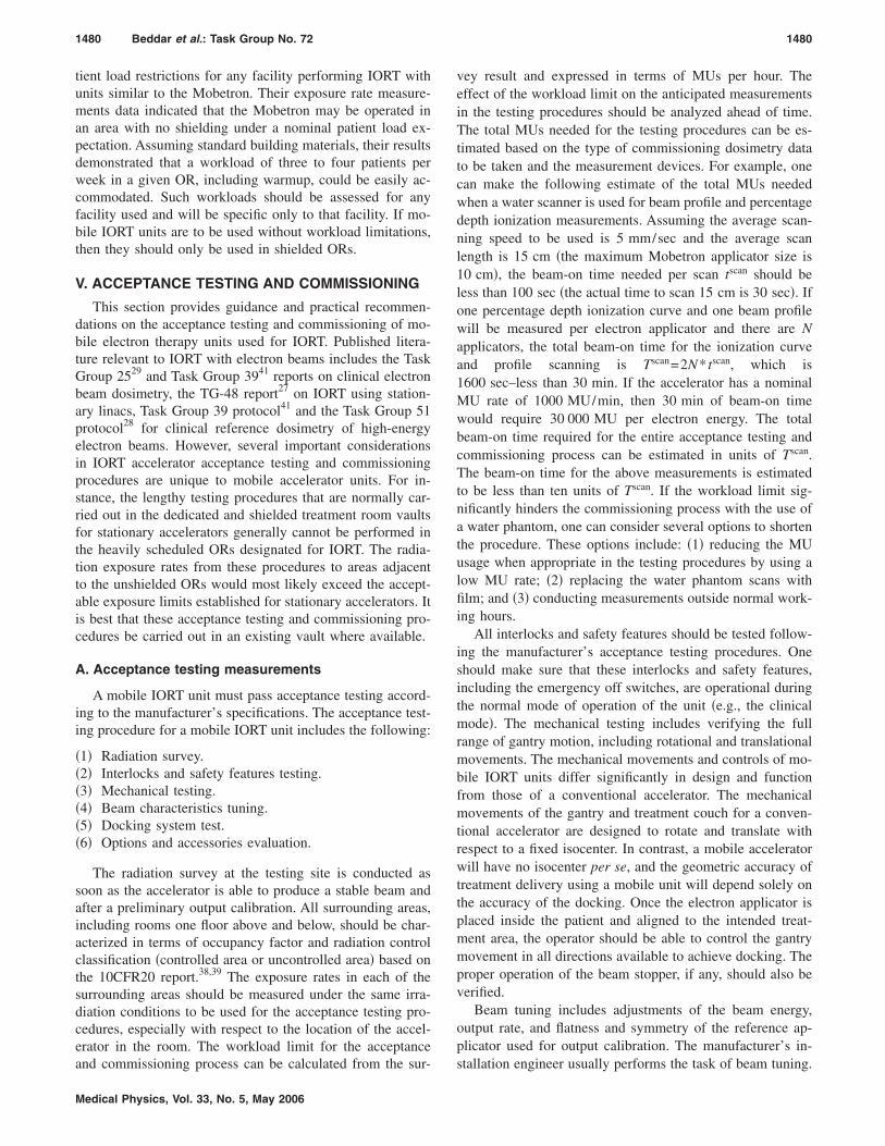
1480 Beddar et al.: Task Group No. 72 1480
tient load restrictions for any facility performing IORT withunits similar to the Mobetron. Their exposure rate measure-ments data indicated that the Mobetron may be operated inan area with no shielding under a nominal patient load ex-pectation. Assuming standard building materials, their resultsdemonstrated that a workload of three to four patients perweek in a given OR, including warmup, could be easily ac-commodated. Such workloads should be assessed for anyfacility used and will be specific only to that facility. If mo-bile IORT units are to be used without workload limitations,then they should only be used in shielded ORs.
V. ACCEPTANCE TESTING AND COMMISSIONING
This section provides guidance and practical recommen-dations on the acceptance testing and commissioning of mo-bile electron therapy units used for IORT. Published litera-ture relevant to IORT with electron beams includes the TaskGroup 2529 and Task Group 3941 reports on clinical electronbeam dosimetry, the TG-48 report27 on IORT using station-ary linacs, Task Group 39 protocol41 and the Task Group 51protocol28 for clinical reference dosimetry of high-energyelectron beams. However, several important considerationsin IORT accelerator acceptance testing and commissioningprocedures are unique to mobile accelerator units. For in-stance, the lengthy testing procedures that are normally car-ried out in the dedicated and shielded treatment room vaultsfor stationary accelerators generally cannot be performed inthe heavily scheduled ORs designated for IORT. The radia-tion exposure rates from these procedures to areas adjacentto the unshielded ORs would most likely exceed the accept-able exposure limits established for stationary accelerators. Itis best that these acceptance testing and commissioning pro-cedures be carried out in an existing vault where available.
A. Acceptance testing measurements
A mobile IORT unit must pass acceptance testing accord-ing to the manufacturer’s specifications. The acceptance test-ing procedure for a mobile IORT unit includes the following:
�1� Radiation survey.�2� Interlocks and safety features testing.�3� Mechanical testing.�4� Beam characteristics tuning.�5� Docking system test.�6� Options and accessories evaluation.
The radiation survey at the testing site is conducted assoon as the accelerator is able to produce a stable beam andafter a preliminary output calibration. All surrounding areas,including rooms one floor above and below, should be char-acterized in terms of occupancy factor and radiation controlclassification �controlled area or uncontrolled area� based onthe 10CFR20 report.38,39 The exposure rates in each of thesurrounding areas should be measured under the same irra-diation conditions to be used for the acceptance testing pro-cedures, especially with respect to the location of the accel-erator in the room. The workload limit for the acceptance
and commissioning process can be calculated from the sur-Medical Physics, Vol. 33, No. 5, May 2006
vey result and expressed in terms of MUs per hour. Theeffect of the workload limit on the anticipated measurementsin the testing procedures should be analyzed ahead of time.The total MUs needed for the testing procedures can be es-timated based on the type of commissioning dosimetry datato be taken and the measurement devices. For example, onecan make the following estimate of the total MUs neededwhen a water scanner is used for beam profile and percentagedepth ionization measurements. Assuming the average scan-ning speed to be used is 5 mm/sec and the average scanlength is 15 cm �the maximum Mobetron applicator size is10 cm�, the beam-on time needed per scan tscan should beless than 100 sec �the actual time to scan 15 cm is 30 sec�. Ifone percentage depth ionization curve and one beam profilewill be measured per electron applicator and there are Napplicators, the total beam-on time for the ionization curveand profile scanning is Tscan=2N* tscan, which is1600 sec–less than 30 min. If the accelerator has a nominalMU rate of 1000 MU/min, then 30 min of beam-on timewould require 30 000 MU per electron energy. The totalbeam-on time required for the entire acceptance testing andcommissioning process can be estimated in units of Tscan.The beam-on time for the above measurements is estimatedto be less than ten units of Tscan. If the workload limit sig-nificantly hinders the commissioning process with the use ofa water phantom, one can consider several options to shortenthe procedure. These options include: �1� reducing the MUusage when appropriate in the testing procedures by using alow MU rate; �2� replacing the water phantom scans withfilm; and �3� conducting measurements outside normal work-ing hours.
All interlocks and safety features should be tested follow-ing the manufacturer’s acceptance testing procedures. Oneshould make sure that these interlocks and safety features,including the emergency off switches, are operational duringthe normal mode of operation of the unit �e.g., the clinicalmode�. The mechanical testing includes verifying the fullrange of gantry motion, including rotational and translationalmovements. The mechanical movements and controls of mo-bile IORT units differ significantly in design and functionfrom those of a conventional accelerator. The mechanicalmovements of the gantry and treatment couch for a conven-tional accelerator are designed to rotate and translate withrespect to a fixed isocenter. In contrast, a mobile acceleratorwill have no isocenter per se, and the geometric accuracy oftreatment delivery using a mobile unit will depend solely onthe accuracy of the docking. Once the electron applicator isplaced inside the patient and aligned to the intended treat-ment area, the operator should be able to control the gantrymovement in all directions available to achieve docking. Theproper operation of the beam stopper, if any, should also beverified.
Beam tuning includes adjustments of the beam energy,output rate, and flatness and symmetry of the reference ap-plicator used for output calibration. The manufacturer’s in-
stallation engineer usually performs the task of beam tuning.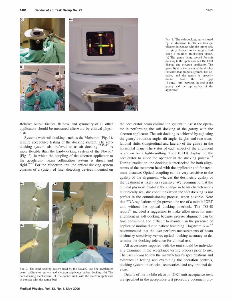
1481 Beddar et al.: Task Group No. 72 1481
Relative output factors, flatness, and symmetry of all otherapplicators should be measured afterward by clinical physi-cists.
Systems with soft docking, such as the Mobetron �Fig. 1�,require acceptance testing of the docking system. The soft-docking system, also referred to as air docking,27,42–45 ismore flexible than the hard-docking system of the Novac7�Fig. 2�, in which the coupling of the electron applicator tothe accelerator beam collimation system is direct andrigid.46,47 For the Mobetron unit, the optical docking systemconsists of a system of laser detecting devices mounted on
FIG. 2. The hard-docking system used by the Novac7. �a� The acceleratorbeam collimation system and electron applicator before docking. �b� Thehard-docking mechanism. �c� The docked unit, with the electron applicator
in contact with the tumor bed.Medical Physics, Vol. 33, No. 5, May 2006
the accelerator beam collimation system to assist the opera-tor in performing the soft docking of the gantry with theelectron applicator. The soft docking is achieved by adjustingthe gantry’s rotation angle, tilt angle, height, and two trans-lational shifts �longitudinal and lateral� of the gantry in thehorizontal plane. The status of each aspect of the alignmentis shown on a light-emitting diode �LED� display on theaccelerator to guide the operator in the docking process.48
During irradiation, the docking is interlocked for both align-ments of the treatment head with the applicator and for treat-ment distance. Optical coupling can be very sensitive to thequality of the alignment, whereas the dosimetric quality ofthe treatment is likely less sensitive. We recommend that theclinical physicist evaluate the change in beam characteristicsat clinically realistic conditions when the soft docking is notperfect in the commissioning process, when possible. Notethat FDA regulations might prevent the use of a mobile IORTunit without the optical docking interlock. The TG-48report27 included a suggestion to make allowances for mis-alignment in soft docking because precise alignment can betime consuming and difficult to maintain in the presence ofapplicator motion due to patient breathing. Hogstrom et al.49
recommended that the user perform measurements of beamdosimetry sensitivity versus optical docking accuracy to de-termine the docking tolerance for clinical use.
All accessories supplied with the unit should be individu-ally examined in the acceptance testing process prior to use.The user should follow the manufacturer’s specifications andtolerance in testing and examining the operation controls,docking system, interlocks, accessories, and any optional de-vices.
Details of the mobile electron IORT unit acceptance tests
FIG. 1. The soft-docking system usedby the Mobetron. �a� The electron ap-plicator, in contact with the tumor bed,is rigidly clamped to the surgical bedusing a modified Bookwalter clamp.�b� The gantry being moved for softdocking to the applicator. �c� The LEDdisplay and electron applicator. Thegreen light in the center of the displayindicates that proper alignment has oc-curred and the gantry is properlydocked. Note the air gap�4 cm±1 mm� between the end of thegantry and the top surface of theapplicator.
are specified in the acceptance test procedure document pro-
1482 Beddar et al.: Task Group No. 72 1482
vided by the manufacturer. Table I, which lists the itemsincluded in the acceptance testing of Mobetron units, isshown as an example.
B. Commissioning and dose measurements
The methodology and equipment that should be used inthe acceptance testing and commissioning of electron beamsfor IORT units should follow the general recommendationsmade in the TG-51 protocol for reference dosimetry on clini-cal electron beams.28 This Task Group �TG-72� recommendsthe use of a water phantom for the beam calibration as de-scribed by TG-51. The methods for obtaining relative dosim-etry measurements are at the discretion of the responsibleclinical physicist, who must make the decision on the basis
TABLE I. Typical procedures required for acceptance
Procedure
Radiation survey Evo
Mechanical inspection Voo
Radiation safety VBeam characteristics V
flsg
Dosimetry system Vlt
Control console Vc
Docking system VOptions and accessories VSafety features E
a
TABLE II. Typical measurements used in mobile IOR
Measurements
Beam profiles �depth doseand cross plane profiles�
Leakage profiles
Applicator factors
Air gap factors
TG-51 output calibration
Medical Physics, Vol. 33, No. 5, May 2006
of multiple considerations, including radiation safety, theclinical accuracy needed for IORT treatment, commissioningtime frame, resources available, and the limitations andavailability of the measurement devices.
The beam characteristics commonly measured in the com-missioning of a mobile IORT unit are listed in Table II.
This Task Group will not make any further recommenda-tions as far as what type or model of ionization chamber ordetector should be used for clinical reference dosimetry, be-cause this has been covered elsewhere27–29,41,50–52 However,several unique aspects in the commissioning of a mobileIORT unit deserve the user’s attention. Mobile IORT unitshave dose rate outputs several times higher than conven-tional accelerators so that they can deliver large doses �10 to
g of a mobile IORT unit.
Comment
e no individual is exposed to radiation levels inion of regulations, and verify the normal operationergency off switches.the movement range, speed, control, and accuracygantry and beam stopper. Verify the physical sizesapplicators.dose attenuation through the beam stopper.beam energy, surface dose, dose rate, field
ss, symmetry, and x-ray contamination according tocations. Verify beam energy constancy for allangles.the precision of the backup MU chamber, the
ity and reproducibility of the MU chambers, andsimetry interlocks.the normal function of each control on the control
le.the normal function of the optical docking system.normal function.
ine all safety features �emergency off, rad-on light,udible warning sounds�.
t commissioning.
Comment
surements are done for each applicator and beamgy and should extend to regions outside thement area.surements are done for a limited sample oficators and beam energies �including the highest
energy� and should be made lateral to theicator walls at various depths.licator factors are relative to a 10-cm circular cone,the measurements are done at dmax for eachicator and beam energy.air gap factor is the ratio of dose with an air gap toose without one at dmax. Air gap factors are
sured at the appropriate depths of dmax for eachbination of applicator and beam energy.ut calibration is done at the TG-51 reference depthsing the 10-cm circular applicator. From these
surements the dose/MU at dmax is determined.
testin
nsuriolatf emerifyf thef allerifyerifyatnepecifiantryerify
inearhe doerifyonsoerifyerifyxamnd a
T uni
MeaenertreatMeaapplbeamapplAppandapplThethe dmeacomOutpdref umea
1483 Beddar et al.: Task Group No. 72 1483
20 Gy� in a short time �1 to 2 min�. The ion recombinationcorrection factor Pion depends on the dose per pulse in accel-erator beams and thus will change if either the pulse rate fora fixed dose rate or the dose rate is changed.28,29,53 At thehigh dose rates used by mobile IORT units, cylindrical cham-bers can have large values of Pion. For instance, the value ofPion for a �PTW� cylindrical chamber �Model 30006, innerradius 3.05 mm� exposed to a dose rate of 10 Gy/min isgreater than 1.05. However, Pion did not exceed 1.03 for aMarkus PTW parallel plate chamber �Model 23343, sensitivevolume 0.055 cm3�. This Task Group recommends thatchambers with Pion values outside the acceptable rangespecified by TG-51 should not be used for output calibration.
Furthermore, it is essential that the dose per pulse andhence the dose rate be kept fairly stable during data collec-tion, because Pion will no longer be constant and large fluc-tuations in the dose rate over time will therefore affect ion-ization measurements. For instance, when measuringapplicator output factors, it has been observed that, as thedose rate changed from 10 to 15 Gy/min over the course ofone hour, the ion recombination Pion also changed, and thusthe output factors appeared to be changing. However, in nor-mal operation where the beam is not used continuously forlong time periods, the dose rate of a mobile linac is notexpected to vary significantly. For instance, Beddar54 exam-ined the stability of a Mobetron linac over 20 quality assur-ance trials and found variation within ±2%. The author alsofound that hours of inactivity, with the unit powered on �instandby mode� either throughout the day or overnight, led tovariations in output of about 1%.
Piermattei et al.55 found that, with high dose values of 30to 60 mGy per pulse for the Novac7 �compared with 4 to6 mGy per pulse for the Mobetron�, the error in dose result-ing from the use of a parallel plate chamber could be as highas 20% due to overestimation of Pion. For different pulserates, they measured Pion from the ratio of the dose measuredby radiochromic film to that measured by the parallel platechamber uncorrected for ion recombination. Other users of
56
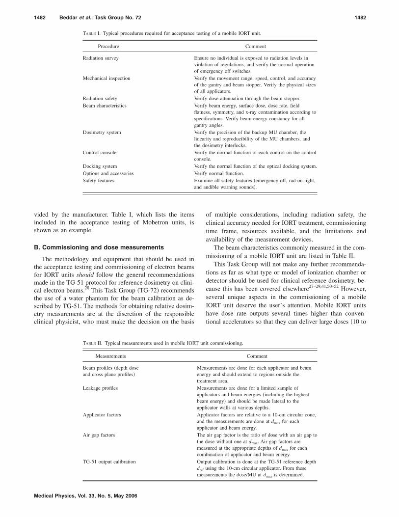
FIG. 3. The central axis percentage depth dose for a 10-cm circular appli-cator from a stationary linear accelerator �Siemens ME, filled circles� and amobile linear accelerator �Mobetron, open circles� for a 6-MeV electronbeam.
the Novac7, because of this ion recombination issue, have
Medical Physics, Vol. 33, No. 5, May 2006
used chemical Fricke dosimeters, provided by the mailed do-simetry service at the Italian Primary Standard DosimetryLaboratory in Rome, and radiochromic films for dosimetry.Di Martino et al.57 have determined the relationship betweenPion and the dose per pulse based on generalized Boagtheory. They found good agreement between percent depthdose �PDD� curves evaluated using Gafchromic films andparallel-plate ionization chambers with values of Pion deter-mined for doses of 30 to 130 mGy per pulse. This TaskGroup recommends determining Pion using the standard two-voltage technique described in TG-51 for doses less than10 mGy per pulse, and using an alternate method for higherdoses per pulse as suggested by the Novac7 users.55–57
Another aspect of commissioning a mobile IORT unit isthe lack of a gantry isocenter and a surgical bed with precisemovement control. Additional time is needed to set up awater phantom. The beam stopper on a mobile IORT unitmay also prevent the use of the water phantom support sys-
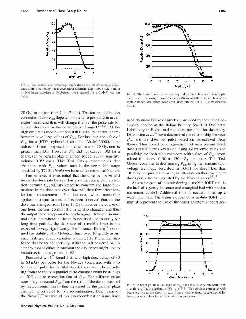
FIG. 4. The central axis percentage depth dose for a 10-cm circular appli-cator from a stationary linear accelerator �Siemens ME, filled circles� and amobile linear accelerator �Mobetron, open circles� for a 12-MeV electronbeam.
FIG. 5. A beam profile at the depth of dmax for a 6-MeV electron beam froma stationary linear accelerator �Siemens ME, filled circles� compared withbeam profiles at the depth of dmax from a mobile linear accelerator �Mo-
betron, open circles� for a 10-cm electron applicator.
1484 Beddar et al.: Task Group No. 72 1484
tem �e.g., table support� that normally comes with most com-mercial phantom scanners. It may be necessary to build aspecial low table that straddles the beam stopper.
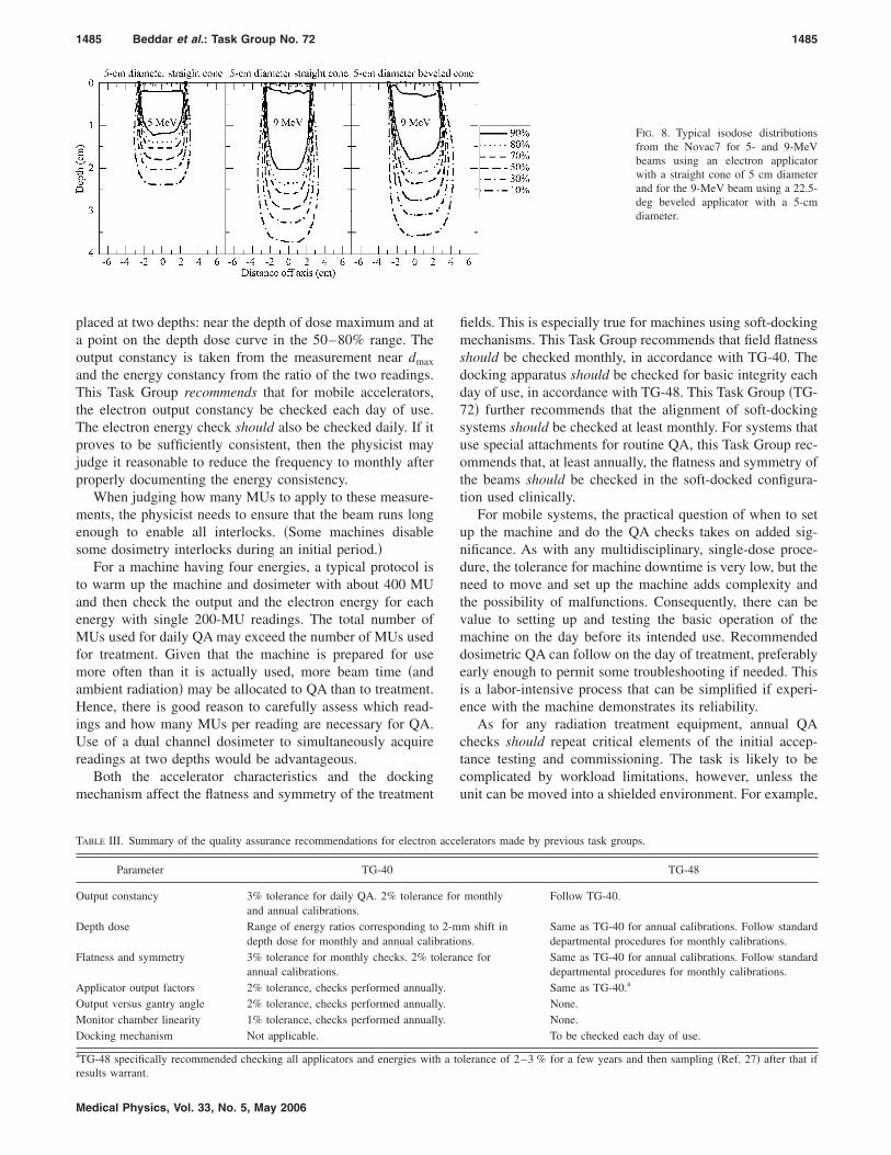
Figures 3 and 4 show the central axis depth dose curvesfor 6- and 12-MeV electron beams, respectively, from a sta-tionary linac �Siemens� compared with those from a mobilelinac �Mobetron� for a 10-cm electron applicator. All depthdose curves were measured using the method described bythe TG-51 protocol28 The depth dose curves of the mobileunit have a higher surface dose, which can be attributed to agreater proportion of energy-degraded, scattered electrons inthe beam. Figures 5 and 6 show beam profiles at the depthdmax for 6 and 12 MeV electron beams obtained from a con-ventional accelerator �Siemens� and a mobile IORT unit�Mobetron�. The difference between the flatness and symme-try curves shown in Figs. 5 and 6 can be attributed to differ-ences in the source-to-surface distance variation and the scat-tering foil design. The mobile units have smaller horns intheir beam profiles, a desirable feature for delivery of a uni-form dose within an IORT field. Typical isodose distributionsfor IORT mobile units are shown in Figs. 7 �Mobetron� and8 �Novac7�. Leakage beam profiles that extend beyond theapplicator walls are needed to estimate the dose to normal
FIG. 6. A beam profile at the depth of dmax for a 12-MeV electron beamfrom a stationary linear accelerator �Siemens ME, filled circles� comparedwith beam profiles at the depth of dmax from a mobile linear accelerator�Mobetron, open circles� for a 10-cm electron applicator.
Medical Physics, Vol. 33, No. 5, May 2006
tissue close to the applicator. This was discussed in theTG-48 report,27 which also included typical scans measuredlateral to the applicator walls.
VI. RECOMMENDED QUALITY ASSURANCE
Individual state regulations require certain QA practicesfor medical linacs; these requirements differ from state tostate, and some may not be well suited to these special-purpose devices. The physicist must ensure that the use ofmobile IORT equipment complies with any relevant regula-tions and/or apply for exemptions where justified.
A. Previous quality assurance recommendations formedical linear accelerators
Any discussion of QA for mobile linacs used for IORTmust acknowledge the recommendations published in theTask Group 40 report.58 regarding QA for medical linacs ingeneral. In addition, the TG-48 report27 discussed specificQA issues for linacs used for IORT. Table III summarizes thepertinent recommendations of these previous, complemen-tary reports regarding dosimetric and mechanical QA.
B. Quality assurance for mobile electron accelerators
When adapting these recommendations to mobile accel-erators, the clinical physicist needs to deal with some con-flicting considerations. These units are partially disassembledand transported each day of use. They forgo adjustable col-limator jaws and eliminate bending magnets to reduceweight and radiation leakage. These design elements sim-plify the system, but they make the electron beam energymore dependent on variations in rf power generation andcoupling to the accelerator. Therefore, on one hand, there arereasons to perform more frequent beam measurements thanwith conventional installations. On the other hand, the equip-ment is used in ORs with little or no added shielding, soradiation safety considerations argue for limiting the beamtime for QA as much as possible. These competing concernscan be partially resolved by developing an efficient QA pro-cess, but they do present an ongoing challenge.
Output and energy can be checked efficiently with the useof a dedicated solid phantom in which a dosimeter can be
FIG. 7. Typical isodose distributionsmeasured from the Mobetron for the4- and 12-MeV beams using the larg-est applicator �10-cm diameter�, asmaller applicator �4-cm diameter�,and an applicator with a 30-deg bevel�5-cm diameter�.
1485 Beddar et al.: Task Group No. 72 1485
placed at two depths: near the depth of dose maximum and ata point on the depth dose curve in the 50–80% range. Theoutput constancy is taken from the measurement near dmax
and the energy constancy from the ratio of the two readings.This Task Group recommends that for mobile accelerators,the electron output constancy be checked each day of use.The electron energy check should also be checked daily. If itproves to be sufficiently consistent, then the physicist mayjudge it reasonable to reduce the frequency to monthly afterproperly documenting the energy consistency.
When judging how many MUs to apply to these measure-ments, the physicist needs to ensure that the beam runs longenough to enable all interlocks. �Some machines disablesome dosimetry interlocks during an initial period.�
For a machine having four energies, a typical protocol isto warm up the machine and dosimeter with about 400 MUand then check the output and the electron energy for eachenergy with single 200-MU readings. The total number ofMUs used for daily QA may exceed the number of MUs usedfor treatment. Given that the machine is prepared for usemore often than it is actually used, more beam time �andambient radiation� may be allocated to QA than to treatment.Hence, there is good reason to carefully assess which read-ings and how many MUs per reading are necessary for QA.Use of a dual channel dosimeter to simultaneously acquirereadings at two depths would be advantageous.
Both the accelerator characteristics and the dockingmechanism affect the flatness and symmetry of the treatment
TABLE III. Summary of the quality assurance recommendations for electron
Parameter TG-40
Output constancy 3% tolerance for daily QA. 2% tolerancand annual calibrations.
Depth dose Range of energy ratios corresponding todepth dose for monthly and annual calib
Flatness and symmetry 3% tolerance for monthly checks. 2% toannual calibrations.
Applicator output factors 2% tolerance, checks performed annualOutput versus gantry angle 2% tolerance, checks performed annualMonitor chamber linearity 1% tolerance, checks performed annualDocking mechanism Not applicable.
aTG-48 specifically recommended checking all applicators and energies wit
results warrant.Medical Physics, Vol. 33, No. 5, May 2006
fields. This is especially true for machines using soft-dockingmechanisms. This Task Group recommends that field flatnessshould be checked monthly, in accordance with TG-40. Thedocking apparatus should be checked for basic integrity eachday of use, in accordance with TG-48. This Task Group �TG-72� further recommends that the alignment of soft-dockingsystems should be checked at least monthly. For systems thatuse special attachments for routine QA, this Task Group rec-ommends that, at least annually, the flatness and symmetry ofthe beams should be checked in the soft-docked configura-tion used clinically.
For mobile systems, the practical question of when to setup the machine and do the QA checks takes on added sig-nificance. As with any multidisciplinary, single-dose proce-dure, the tolerance for machine downtime is very low, but theneed to move and set up the machine adds complexity andthe possibility of malfunctions. Consequently, there can bevalue to setting up and testing the basic operation of themachine on the day before its intended use. Recommendeddosimetric QA can follow on the day of treatment, preferablyearly enough to permit some troubleshooting if needed. Thisis a labor-intensive process that can be simplified if experi-ence with the machine demonstrates its reliability.
As for any radiation treatment equipment, annual QAchecks should repeat critical elements of the initial accep-tance testing and commissioning. The task is likely to becomplicated by workload limitations, however, unless theunit can be moved into a shielded environment. For example,
lerators made by previous task groups.
TG-48
monthly Follow TG-40.
m shift inns.
Same as TG-40 for annual calibrations. Follow standarddepartmental procedures for monthly calibrations.
ce for Same as TG-40 for annual calibrations. Follow standarddepartmental procedures for monthly calibrations.Same as TG-40.a
None.None.To be checked each day of use.
lerance of 2–3 % for a few years and then sampling �Ref. 27� after that if
FIG. 8. Typical isodose distributionsfrom the Novac7 for 5- and 9-MeVbeams using an electron applicatorwith a straight cone of 5 cm diameterand for the 9-MeV beam using a 22.5-deg beveled applicator with a 5-cmdiameter.
acce
e for
2-mratioleran
ly.ly.ly.
h a to
1486 Beddar et al.: Task Group No. 72 1486
it may be necessary to use film instead of a scanning waterphantom. If the initial commissioning and subsequent annualQA tests are to be done in different environments with dif-ferent dosimeters, then appropriate baseline measurementsshould be done during the commissioning.
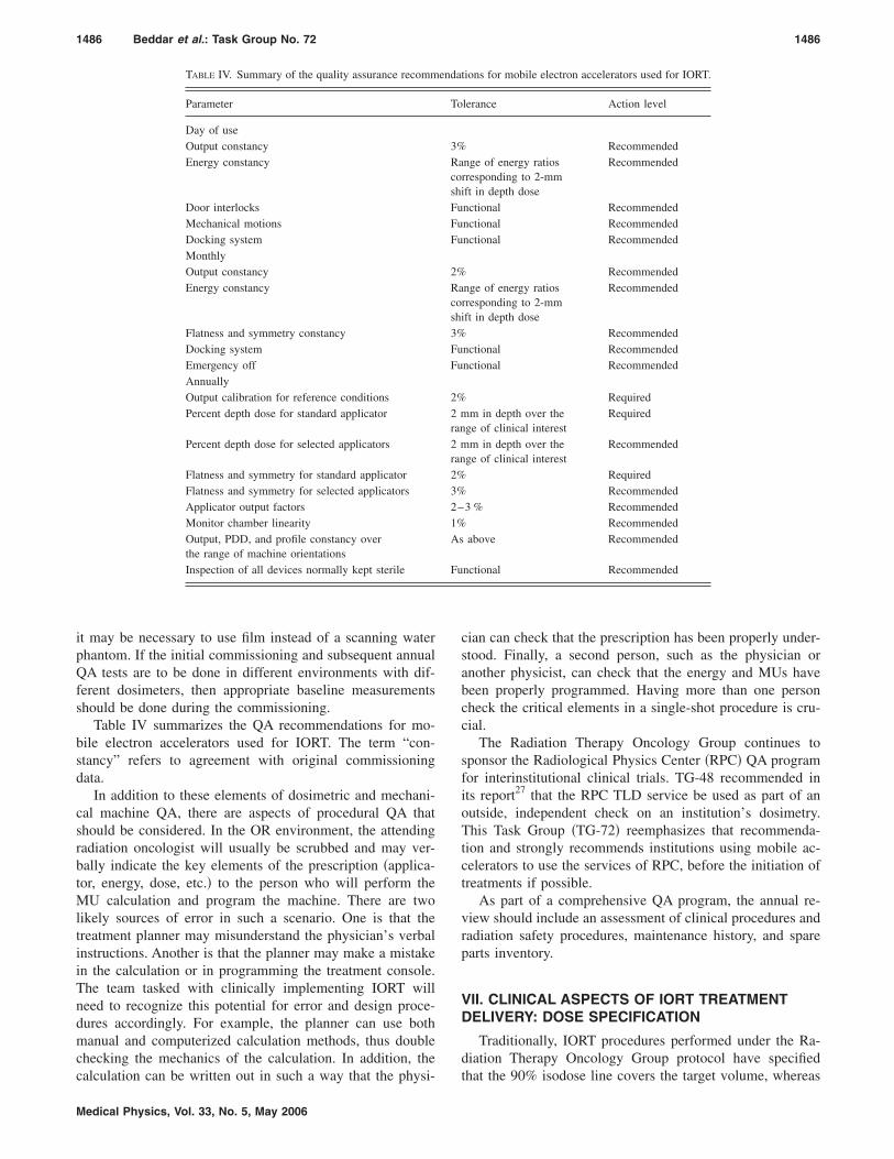
Table IV summarizes the QA recommendations for mo-bile electron accelerators used for IORT. The term “con-stancy” refers to agreement with original commissioningdata.
In addition to these elements of dosimetric and mechani-cal machine QA, there are aspects of procedural QA thatshould be considered. In the OR environment, the attendingradiation oncologist will usually be scrubbed and may ver-bally indicate the key elements of the prescription �applica-tor, energy, dose, etc.� to the person who will perform theMU calculation and program the machine. There are twolikely sources of error in such a scenario. One is that thetreatment planner may misunderstand the physician’s verbalinstructions. Another is that the planner may make a mistakein the calculation or in programming the treatment console.The team tasked with clinically implementing IORT willneed to recognize this potential for error and design proce-dures accordingly. For example, the planner can use bothmanual and computerized calculation methods, thus doublechecking the mechanics of the calculation. In addition, the
TABLE IV. Summary of the quality assurance recomm
Parameter
Day of useOutput constancyEnergy constancy
Door interlocksMechanical motionsDocking systemMonthlyOutput constancyEnergy constancy
Flatness and symmetry constancyDocking systemEmergency offAnnuallyOutput calibration for reference conditionsPercent depth dose for standard applicator
Percent depth dose for selected applicators
Flatness and symmetry for standard applicatorFlatness and symmetry for selected applicatorsApplicator output factorsMonitor chamber linearityOutput, PDD, and profile constancy overthe range of machine orientationsInspection of all devices normally kept sterile
calculation can be written out in such a way that the physi-
Medical Physics, Vol. 33, No. 5, May 2006
cian can check that the prescription has been properly under-stood. Finally, a second person, such as the physician oranother physicist, can check that the energy and MUs havebeen properly programmed. Having more than one personcheck the critical elements in a single-shot procedure is cru-cial.
The Radiation Therapy Oncology Group continues tosponsor the Radiological Physics Center �RPC� QA programfor interinstitutional clinical trials. TG-48 recommended inits report27 that the RPC TLD service be used as part of anoutside, independent check on an institution’s dosimetry.This Task Group �TG-72� reemphasizes that recommenda-tion and strongly recommends institutions using mobile ac-celerators to use the services of RPC, before the initiation oftreatments if possible.
As part of a comprehensive QA program, the annual re-view should include an assessment of clinical procedures andradiation safety procedures, maintenance history, and spareparts inventory.
VII. CLINICAL ASPECTS OF IORT TREATMENTDELIVERY: DOSE SPECIFICATION
Traditionally, IORT procedures performed under the Ra-diation Therapy Oncology Group protocol have specified
tions for mobile electron accelerators used for IORT.
lerance Action level
Recommendednge of energy ratiosrresponding to 2-mmift in depth dose
Recommended
nctional Recommendednctional Recommendednctional Recommended
Recommendednge of energy ratiosrresponding to 2-mmift in depth dose
Recommended
Recommendednctional Recommendednctional Recommended
Requiredm in depth over the
ge of clinical interestRequired
m in depth over thege of clinical interest
Recommended
RequiredRecommended
3 % RecommendedRecommended
above Recommended
nctional Recommended
enda
To
3%RacoshFuFuFu
2%Racosh3%FuFu
2%2 mran2 mran2%3%2–1%As
Fu
that the 90% isodose line covers the target volume, whereas
1487 Beddar et al.: Task Group No. 72 1487
the International Commission on Radiation Units �ICRU�and Measurements Report 35 �Ref. 59� recommends that thedose be prescribed at dmax. Therefore, TG-48 recommendedthat both the 90% dose and the maximum dose should bereported. Since the publication of the TG-48 report, neitherthe ICRU nor any other institution has achieved a formalagreement on dose specification for IORT. However mostIORT groups follow the convention of prescribing to the90% isodose level to ensure coverage of the target by the90% isodose line. This Task Group recommends that thedose be prescribed at the 90% isodose level and then thedose be reported at both the 90% level and dmax.
VIII. RECOMMENDATIONS FOR FUTURECONSIDERATIONS
Many aspects of IORT are still in an investigative and lessstandardized state than external beam radiation therapy.Therefore, in existing IORT programs, several centers havedeveloped specialized applicators,4,8,42,45,47,60,61 alignmentaids,62 and other technical equipment to adapt to institutionalmethods or requirements, such as patient case selection andsurgical techniques. For instance, the treatment of extendedtumor sites �e.g., sarcomas located on extremities� may re-quire the development of applicators and techniques for fieldabutment.8 Other design features of mobile IORT machinesmay limit the development of some specialized equipment.Adaptations of site-developed equipment, and possibly ad-vice by the manufacturer, may be necessary to allow for theuse of the soft-docking aids provided with the linacs.
The management of cancer using IORT is limited to thedelivery of one single dose during surgery, which is an oc-casional modality that can hardly be postponed or repeated.Therefore, machine interlocks, which exclude patient treat-ment, should be restricted to those that are necessary to war-rant patient safety and to avoid machine damage. Interlocksof lower priority �e.g., those that are triggered by slight ap-plicator misalignments or machine instability� should be welldocumented and their effect on the dose distribution wellquantified so that, if necessary, an override can be consideredat the time of treatment. Apart from few early phantom mea-surements on beam inclination and gaps,33,42,49 the effects ofbeam misalignment, gaps, bolus, changes of penumbra, andtissue inhomogeneities in realistic patient geometries are notwell investigated. Further research is needed in these areas,and further development is necessary in the treatment plan-ning of IORT for realistic patient geometries.
ACKNOWLEDGMENTS
The members of TG-72 wish to thank the followingphysicists for their contributions concerning the Novac7: Gi-ampiero Tosi and Mario Ciocca, Istituto Europeo di Oncolo-gia, Milano, Italy, Assunta Petrucci, Azienda Complesso SanFilippo Neri, Rome, Italy, and Axel Schmachtenberg, De-partment of Radiation Oncology, University Clinics, Aachen,
Germany. We thank M. Saiful Huq of the University of Pitts-Medical Physics, Vol. 33, No. 5, May 2006
burgh Cancer Institute, James M. Balter of the University ofMichigan, and Rasika Rajapakshe of the British ColumbiaCancer Agency for their detailed reviews of this report. Wealso acknowledge M. Saiful Huq for helpful teleconferencediscussions and suggestions with the Task Group. Finally, wethank the members of the Radiation Therapy Committee ofthe AAPM chaired by Michael G. Herman.
a�Electronic address: [email protected]. Beck, “On external Roentgen treatment of internal structures �eventra-tion treatment�,” N. Y. Med. Journal 89, 621–622 �1909�.
2M. Abe, “Intraoperative radiotherapy – past, present and future,” Int. J.Radiat. Oncol., Biol., Phys. 10, 1987–1990 �1984�.
3M. Abe, M. Fukuda, K. Yamano, S. Matsuda, and H. Handa, “Intra-operative irradiation in abdominal and cerebral tumours,” Acta Radiol.10, 408–416 �1971�.
4M. Abe and M. Takahashi, “Intraoperative radiotherapy, The Japaneseexperience,” Int. J. Radiat. Oncol., Biol., Phys. 7, 863–868 �1981�.
5A. Goldson, “Preliminary clinical experience with intraoperative radio-therapy �IORT�,” Semin. Oncol. 8, 59–65 �1978�.
6L. L. Gunderson, W. U. Shipley, and H. D. Suit, “Intraoperative irradia-tion a pilot study external beam photons with ‘boost’ dose intraoperativeelectrons,” Cancer 49, 2259–2266 �1982�.
7J. Tepper and W. F. Sindelar, “Summary of the workshop on intraopera-tive radiation therapy,” Cancer Treat. Rep. 65, 911–918 �1981�.
8B. A. Fraass, R. W. Miller, T. J. Kinsella, W. F. Sindelar, F. S. Harrington,K. Yeakel, J. Van de Geijn, and E. Glatstein, “Intraoperative radiationtherapy at the National Cancer Institute, technical innovation and dosim-etry,” Int. J. Radiat. Oncol., Biol., Phys. 11, 1299–1311 �1985�.
9L. R. Coia and G. E. Hanks, “The need for subspecialization intraopera-tive radiation therapy,” Int. J. Radiat. Oncol., Biol., Phys. 24, 891–893�1992�.
10L. L. Gunderson, D. M. Nagorney, D. C. McIlrath, J. M. Fieck, H. S.Wieand, A. Martinez, D. J. Pritchard, F. Sim, J. A. Martenson, J. H.Edmonson, and J. H. Donohue, “External beam and intraoperative elec-tron irradiation for locally advanced soft tissue sarcomas,” Int. J. Radiat.Oncol., Biol., Phys. 25, 647–656 �1993�.
11S. Nag, J. Mills, E. Martin, C. Bauer, and J. Grecula, “IORT using high-dose-rate brachytherapy or electron beam for colorectal carcinoma,”Front. Radiat. Ther. Oncol. 31, 238–242 �1997�.
12Y. Hashiguchi, T. Sekine, H. Sakamoto, Y. Tanaka, T. Kazumoto, S. Kato,M. Sakura, Y. Fuse, and Y. Suda, “Intraoperative irradiation after surgeryfor locally recurrent rectal cancer,” Dis. Colon Rectum 42, 886–893;discussion 893–895 �1999�.
13N. J. Sanfilippo, C. H. Crane, J. Skibber, B. Feig, J. L. Abbruzzese, S.Curley, J. N. Vauthey, L. M. Ellis, P. Hoff, R. A. Wolff, T. D. Brown, K.Cleary, A. Wong, T. Phan, and N. A. Janjan, “T4 rectal cancer treatedwith preoperative chemoradiation to the posterior pelvis followed by mul-tivisceral resection: patterns of failure and limitations of treatment,” Int. J.Radiat. Oncol., Biol., Phys. 51, 176–183 �2001�.
14C. G. Willett, H. D. Suit, J. E. Tepper, H. J. Mankin, K. Convery, A. L.Rosenberg, and W. C. Wood, “Intraoperative electron beam radiationtherapy for retroperitoneal soft tissue sarcoma,” Cancer 68, 278–283�1991�.
15P. W. Pisters, M. T. Ballo, M. J. Fenstermacher, B. W. Feig, K. K. Hunt,K. A. Raymond, M. A. Burgess, G. K. Zagars, R. E. Pollock, R. S.Benjamin, and S. R. Patel, “Phase I trial of preoperative concurrent doxo-rubicin and radiation therapy, surgical resection, and intraoperativeelectron-beam radiation therapy for patients with localized retroperitonealsarcoma,” J. Clin. Oncol. 21, 3092–3097 �2003�.
16T. J. Kinsella and W. F. Sindelar, “Intraoperative radiotherapy for pancre-atic carcinoma. Experimental and clinical studies,” Cancer 78, 598–604�1996�.
17W. F. Sindelar and T. J. Kinsella, “Studies of intraoperative radiotherapyin carcinoma of the pancreas,” Ann. Oncol. 10 Suppl 4, 226–230 �1999�.
18C. H. Crane, A. S. Beddar, and D. B. Evans, “The role of intraoperativeradiotherapy in pancreatic cancer,” Surg. Oncol. Clin. N. Am. 12, 965–977 �2003�.
19M. A. Mahe, J. P. Gerard, J. B. Dubois, A. Roussel, E. Bussieres, M.Delannes, F. Guillemin, T. Schmitt, D. Dargent, Y. Guillard, P. Martel, P.
Richaud, J. C. Cuilliere, J. De Ranieri, and L. Malissard, “Intraoperative
1488 Beddar et al.: Task Group No. 72 1488
radiation therapy in recurrent carcinoma of the uterine cervix: report ofthe French intraoperative group on 70 patients,” Int. J. Radiat. Oncol.,Biol., Phys. 34, 21–26 �1996�.
20J. P. Gerard, G. Collin, L. Ayzac, D. Dargent, D. Raudrant, F. N. Gilly, P.Romestaing, I. Sentenac, and R. Coquard, “The role of IORT as salvagetherapy for recurrent cervical and endometrial carcinoma,” Front. Radiat.Ther. Oncol. 31, 260–262 �1997�.
21R. Martinez-Monge, M. Jurado, J. J. Aristu, M. Moreno, M. Cambeiro, A.Perez-Ochoa, G. Lopez-Garcia, and J. L. Alcazar, “Intraoperative electronbeam radiotherapy during radical surgery for locally advanced and recur-rent cervical cancer,” Gynecol. Oncol. 82, 538–543 �2001�.
22E. G. Shaw, L. L. Gunderson, J. K. Martin, R. W. Beart, D. M. Nagorney,and K. C. Podratz, “Peripheral nerve and ureteral tolerance to intraopera-tive radiation therapy: clinical and dose-response analysis,” Radiother.Oncol. 18, 247–255 �1990�.
23F. A. Calvo, J. J. Aristu, O. Abuchaibe, J. Rebollo, O. Fernandez Hidalgo,J. Zudaire, J. M. Berian, and I. Azinovic, “Intraoperative and externalpreoperative radiotherapy in invasive bladder cancer: effect of neoadju-vant chemotherapy in tumor downstaging,” Am. J. Clin. Oncol. 16,61–66 �1993�.
24F. A. Calvo, J. Aristu, I. Azinovic, R. Martinez, M. Santos, D. Ortiz deUrbina, and J. M. Berian, “�Intraoperative radiotherapy with acceleratedelectrons for urinary bladder carcinoma: principles and results�,” Arch.Esp. Urol., 52, 649–654 �1999�.
25M. G. del Carmen, B. Eisner, C. G. Willet, and A. F. Fuller, “Intraopera-tive radiation therapy in the management of gynecologic and genitouri-nary malignancies,” Surg. Oncol. Clin. N. Am. 12, 1031–1042 �2003�.
26A. S. Beddar and S. Krishnan, “Intraoperative radiotherapy using a mo-bile linear electron accelerator: A retroperitoneal sarcoma case,” J. Appl.Clin. Med. Phys. 6, 95–107 �2005�.
27J. R. Palta, P. J. Biggs, D. J. Hazle, M. S. Huq, R. A. Dahl, T. G. Ochran,J. Soen, R. R. Dobelbower, and E. C. McCullough, “Intraoperative elec-tron beam radiation therapy, technique, dosimetry, and dose specification,report of Task Group 48 of the radiation therapy committee, AmericanAssociation of Physicists in Medicine,” Int. J. Radiat. Oncol., Biol., Phys.33, 725–746 �1995�.
28P. R. Almond, P. J. Biggs, B. M. Coursey, W. F. Hanson, M. S. Huq, R.Nath, and D. W. O. Rogers, “AAPM’s TG-51 protocol for clinical refer-ence dosimetry of high-energy photon and electron beams,” Med. Phys.26, 1847–1870 �1999�.
29F. M. Khan, K. P. Doppke, K. R. Hogstrom, G. J. Kutcher, R. Nath, S. C.Prasad, J. A. Purdy, M. Rozenfeld, and B. L. Werner, “Clinical electronbeam dosimetry, Report of AAPM radiation therapy committee TaskGroup 25,” Med. Phys. 18, 73–109 �1991�.
30A. S. Beddar, P. J. Biggs, S. Chang, G. A. Ezzell, B. A. Faddegon, F. W.Hensley, and M. D. Mills, “Intraoperative radiation therapy using mobileelectron linear accelerators: Report of AAPM Radiation Therapy Com-mittee Task Group No. 72 �unabridged electronic version�,” �AAPM,2006�.
31E. C. McCullough, “Intraoperative Electron Beam Radiation Therapy�IORT�,” in Radiation Oncology Physics—1990. American Association ofPhysicists in Medicine, Medical Physics Monograph No. 19, edited by J.A. Purdy �American Institute of Physics, New York, 1992�, pp. 480–490.
32E. C. McCullough and P. J. Biggs, “Physical Aspects of Intra-OperativeElectron Beam Irradiation, in Intraoperative Radiation, Techniques andResults, edited by L. L. Gunderson, C. G. Willett, L. B. Harrison, and F.A. Calvo �Humana Press, New Jersey, 1999�.
33P. J. Biggs, E. R. Epp, C. C. Ling, D. H. Novack, and H. B. Michaels,“Dosimetry field shaping and other considerations for intra-operativeelectron therapy,” Int. J. Radiat. Oncol., Biol., Phys. 7, 875–884 �1981�.
34M. A. Domanovic, M. Ouzidane, R. J. Ellis, T. J. Kinsella, and A. S.Beddar, “Using intraoperative radiation therapy—A case study,” AORNJ. 77, 412–417 �2003�.
35A. S. Beddar, M. L. Kubo, M. A. Domanovic, R. J. Ellis, T. J. Kinsella,and C. H. Sibata, “A new approach to intraoperative radiation therapy,”AORN J. 74, 500–505 �2001�.
36J. L. Daves and M. D. Mills, “Shielding assessment of a mobile electronaccelerator for intraoperative radiotherapy,” J. Appl. Clin. Med. Phys. 2,165–173 �2001�.
37“Limitation to Exposure from Ionizing Radiation, NCRP Report 116”�National Council on Radiation Protection and Measurements, Bethesda,MD, 1993�.
38
U.S. Nuclear Regulatory Commission, “Title 10 Code of Federal Regu-Medical Physics, Vol. 33, No. 5, May 2006
lations 20.1201” �U.S. Government Printing Office, Washington, D.C.,1998�.
39U.S. Nuclear Regulatory Commission, “Title 10 Code of Federal Regu-lations 20.1301�a�” �U.S. Government Printing Office, Washington, D.C.,1998�.
40M. D. Mills, L. C. Fajardo, D. L. Wilson, J. L. Daves, and W. J. Spanos,“Commissioning of a mobile electron accelerator for intraoperative radio-therapy,” J. Appl. Clin. Med. Phys. 2, 121–130 �2001�.
41P. R. Almond, F. H. Attix, L. J. Humphries, H. Kubo, R. Nath, S. Goetsch,and D. W. O. Rogers, “The calibration and use of plane-parallel ionizationchambers for dosimetry of electron beams: An extension of the 1983AAPM protocol report of the AAPM Radiation Therapy Committee TaskGroup No. 39,” Med. Phys. 21, 1251–1260 �1994�.
42J. R. Palta and N. Suntharalingam, “A nondocking intraoperative electronbeam applicator system,” Int. J. Radiat. Oncol., Biol., Phys. 17, 411–417�1989�.
43H. Kharrati, P. Aletti, and F. Guillemin, “Design of a non-docking intra-operative electron beam applicator system,” Radiother. Oncol. 33, 80–83�1994�.
44D. Jones, E. Taylor, J. Travaglini, and S. Vermeulen, “A non-contactingintraoperative electron cone apparatus,” Int. J. Radiat. Oncol., Biol., Phys.16, 1643–1647 �1989�.
45P. Björk, T. Knöös, P. Nilsson, and K. Larsson, “Design and dosimetrycharacteristics of a soft-docking system for intraoperative radiationtherapy,” Int. J. Radiat. Oncol., Biol., Phys. 47, 527–533 �2000�.
46N. Papanikolaou and B. Paliwal, “The study of the effect of cone shield-ing on intraoperative radiotherapy,” Med. Phys. 22, 571–575 �1995�.
47R. A. Price and K. M. Ayyangar, “IORT apparatus design improvementthrough the evaluation of electron spectral distributions using MonteCarlo methods,” Med. Phys. 27, 215–220 �1999�.
48A. S. Beddar, M. A. Domanovic, M. L. Kubo, R. J. Ellis, C. H. Sibata,and T. J. Kinsella, “Mobile linear accelerators for intraoperative radiationtherapy,” AORN J. 74, 700–705 �2001�.
49K. R. Hogstrom, A. L. Boyer, A. S. Shiu, T. G. Ochran, S. M. Kirsner, F.Krispel, and T. A. Rich, “Design of metallic electron beam cones for anintraoperative therapy linear accelerator,” Int. J. Radiat. Oncol., Biol.,Phys. 18, 1223–1232 �1990�.
50P. Björk, T. Knöös, and P. Nilsson, “Measurements of output factors withdifferent detector types and Monte Carlo calculations of stopping-powerratios for degraded electron beams,” Phys. Med. Biol. 49, 4493–4506�2004�.
51P. Björk, P. Nilsson, and T. Knöös, “Dosimetry characteristics of degradedelectron beams investigated by Monte Carlo calculations in a setup forintraoperative radiation therapy,” Phys. Med. Biol. 47, 239–256 �2002�.
52A. S. Beddar and R. C. Tailor, “Calibration of low-energy electron beamsfrom a mobile linear accelerator with plane-parallel chambers using bothTG-51 and TG-21 protocols,” Phys. Med. Biol. 49, N105–N110 �2004�.
53J. W. Boag and J. Currant, “Current Collection and Ionic Recombinationin Small Cylindrical Ionization Chambers Exposed to Pulsed Radiation,”Br. J. Radiol. 53, 471–478 �1980�.
54A. S. Beddar, “Stability of a mobile electron linear accelerator system forintraoperative radiation therapy,” Med. Phys. 32, 3346–3349 �2005�.
55A. Piermattei, S. delle Canne, L. Azario, A. Russo, A. Fidanzio, R.Miceli, A. Soriani, A. Orvieto, and M. Fantini, “The saturation loss forplane parallel ionization chambers at high dose per pulse values,” Phys.Med. Biol. 45, 1869–1883 �2000�.
56M. Ciocca, R. Orecchia, C. Garibaldi, E. Rondi, A. Luini, G. Gatti, M.Intra, P. Veronesi, R. Lazzari, G. Tosi, and U. Veronesi, “In vivo dosim-etry using radiochromic films during intraoperative electron beam radia-tion therapy in early-stage breast cancer,” Radiother. Oncol. 69, 285–289�2003�.
57F. Di Martino, M. Giannelli, A. C. Traino, and M. Lazzeri, “Ion recom-bination correction for very high dose-per-pulse high-energy electronbeams,” Med. Phys. 32, 2204–2210 �2005�.
58G. J. Kutcher, L. Coia, M. Gillin, W. F. Hanson, S. Leibel, R. J. Morton,J. R. Palta, J. A. Purdy, L. E. Reinstein, G. K. Svensson, M. Weller, andL. Wingfield, “Comprehensive QA for radiation oncology, Report ofAAPM Radiation Therapy Committee Task Group 40,” Med. Phys. 21,581–618 �1994�.
59“ICRU Report 35. Radiation Dosimetry: Electron beams with energiesbetween 1 and 50 MeV” �International Commission on Radiation Unitsand Measurements, Bethesda, MD, 1984�.
60
I. Sentenac, J. P. Gerard, N. Salerno, G. De Laroche, and X. Montbarbon,
1489 Beddar et al.: Task Group No. 72 1489
“Intraoperative Radiation Therapy,” in Radioterapia e Trattamenti Integ-rati �Casa Editrice Ambrosiana, Milano, 1988�, pp. 49–55.
61C. E. Nyerick, T. G. Ochran, A. L. Boyer, and K. Hogstrom, “Dosimetry
characteristics of metallic cones for intraoperative radiotherapy,” Int. J.Medical Physics, Vol. 33, No. 5, May 2006
Radiat. Oncol., Biol., Phys. 21, 501–510 �1991�.62F. J. Prott, N. Willich, S. Palkovic, C. Horch, and H. Wassmann, “A new
method for treatment planning and quality control in IORT of brain tu-
mors,” Front. Radiat. Ther. Oncol. 31, 97–101 �1997�.


![advances in radiotherapy - Europhysics News › articles › epn › pdf › 2012 › 06 › ...[2] AAPM. Stereotactic body radiation therapy: The report of AAPM Task Group 111. Med.Phys.](https://static.fdocuments.net/doc/165x107/5f1bd8d4ed6cbe634218c588/advances-in-radiotherapy-europhysics-news-a-articles-a-epn-a-pdf-a-2012.jpg)