Intracoronary Optical Coherence Tomography (2)
15
Intracoronary Optical Coherence Tomography Biophotonics 585.634.31 Joseph Strakna
-
Upload
joseph-strakna-msabe -
Category
Documents
-
view
142 -
download
0
Transcript of Intracoronary Optical Coherence Tomography (2)
Intracoronary Optical Coherence Tomography
Biophotonics
585.634.31
Joseph Strakna
Coronary Artery Disease
2
• Prevalence: approximately 15 million • Myocardial Infarctions almost 8 million
Mortality • CAD 375 thousand • MI 120 thousand in 2011 AMI results from the blockage of coronary arteries that supply blood to the heart. Caused by thrombus formed by the rupture or erosion of vulnerable plaques within the artery wall. Treatment to restore the blood flow • Thrombolytic therapy • Angioplasty • Coronary artery bypass A method to identify vulnerable plaques prior to eruption or erosion is needed Optical Coherence Tomography offers a method to obtain images with sufficient resolution to characterize the structure of the wall of the coronary artery.

Optical Coherence Tomography
3
Angiography X-ray with contrast Two dimensional view
Coronary artery imaging modalities
Intravascular ultrasound Doppler sound Resolution limited to 100-200 μm
OCT Speed of light High resolution: 15μm Detailed structure
Optical Coherence Tomography
4
OCT is an imaging modality that forms an image from backscattered light History • First described by Huang in 1991 • Earliest application in retinal imaging • Brezinski et al. demonstrated the method could work in non-transparent medium • ICOCT systems available in 2010 in the US • Used in cardiac catheterization labs today

Optical Coherence Tomography
5
OCT is based on Michaelson interferometer Light as e field from a low coherence source is split • Es over sample path length ls • Er over reference path length lr • Sum Ed=Er+Es at detector
Ed =Er0*exp(i(2krlr-ωt)) and Es=Es0*exp(i(2ksls-ωt)) Where: • ω-angular frequency • Ks-source propagation constant • Kr-reference propagation constant
Intensity at detector I(t)=<|Er+ES|>^2= Er0^2+Es0^2+Es0*Er0*cos(2ks*Is-2kr*lr) If we let kl=kr=2πn/λ0 interference term= cos(4πn/λ0*Is-lr) • ls-lr is the optical path length difference between the two arms • Introduces a difference in time of arrival at the detector between the 2 waves • Interference signal amplitude varies with difference in path length • Sample scatterers will interfere if within coherence length • If reference mirror is scanned the axial location scatterers in the sample is scanned )
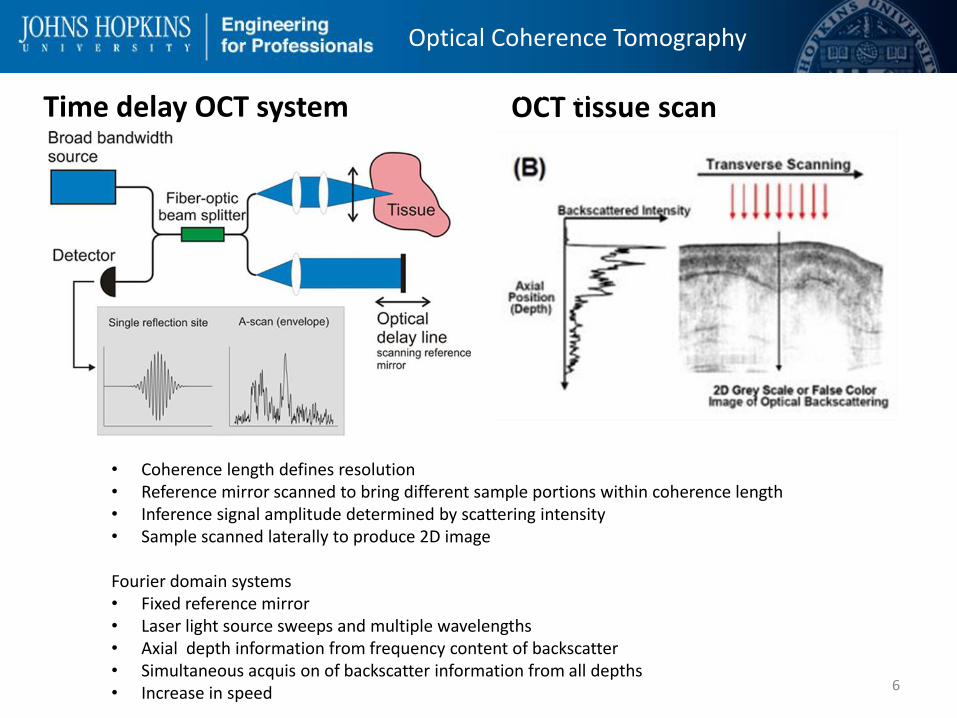
Time delay OCT system OCT tissue scan
6
Optical Coherence Tomography
Optical Coherence Tomography
• Coherence length defines resolution • Reference mirror scanned to bring different sample portions within coherence length • Inference signal amplitude determined by scattering intensity • Sample scanned laterally to produce 2D image Fourier domain systems • Fixed reference mirror • Laser light source sweeps and multiple wavelengths • Axial depth information from frequency content of backscatter • Simultaneous acquis on of backscatter information from all depths • Increase in speed

Optical Coherence Tomography
7
Optical Coherence Tomography
8
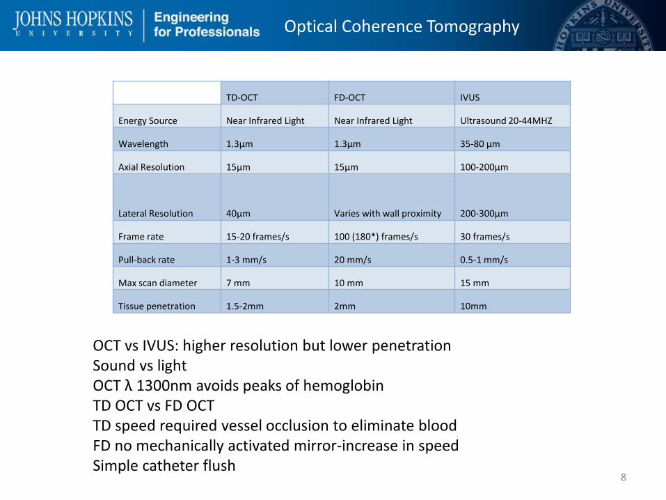
TD-OCT FD-OCT IVUS
Energy Source Near Infrared Light Near Infrared Light Ultrasound 20-44MHZ
Wavelength 1.3μm 1.3μm 35-80 μm
Axial Resolution 15μm 15μm 100-200μm
Lateral Resolution 40μm Varies with wall proximity 200-300μm
Frame rate 15-20 frames/s 100 (180*) frames/s 30 frames/s
Pull-back rate 1-3 mm/s 20 mm/s 0.5-1 mm/s
Max scan diameter 7 mm 10 mm 15 mm
Tissue penetration 1.5-2mm 2mm 10mm
OCT vs IVUS: higher resolution but lower penetration Sound vs light OCT λ 1300nm avoids peaks of hemoglobin TD OCT vs FD OCT TD speed required vessel occlusion to eliminate blood FD no mechanically activated mirror-increase in speed Simple catheter flush
Optical Coherence Tomography
9
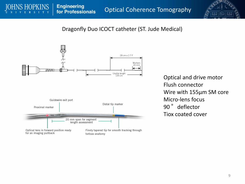
Dragonfly Duo ICOCT catheter (ST. Jude Medical)
Optical and drive motor Flush connector Wire with 155μm SM core Micro-lens focus 90 °deflector Tiox coated cover
Optical Coherence Tomography
10
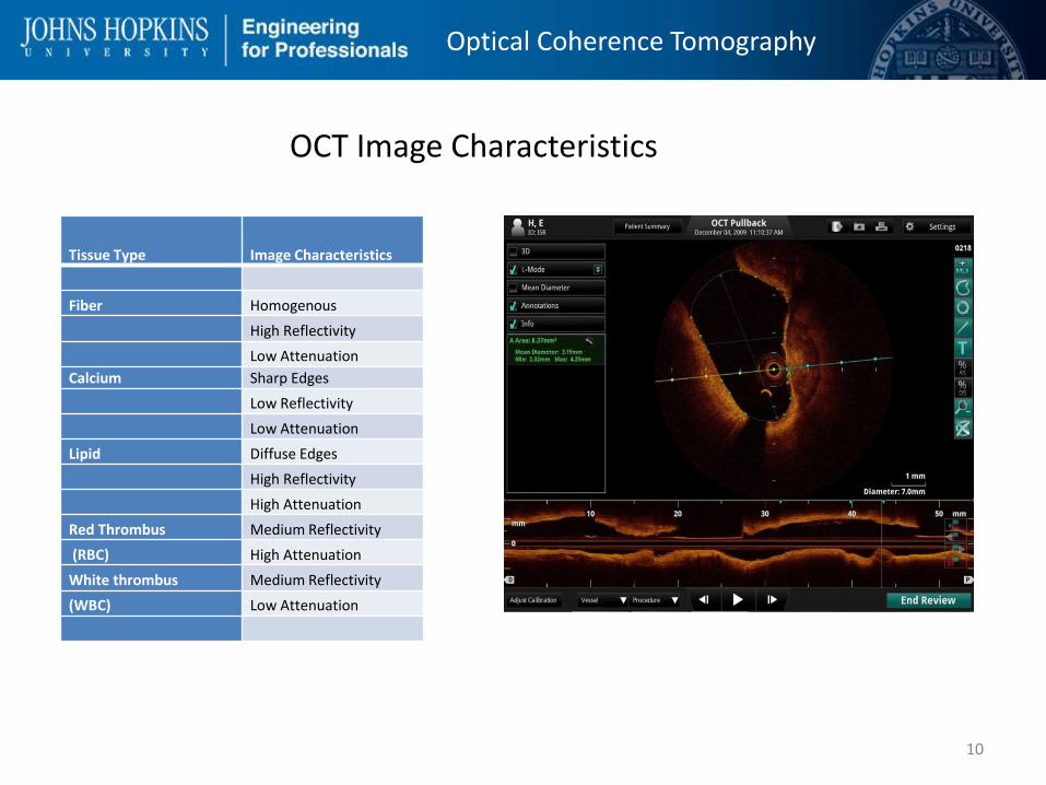
Tissue Type Image Characteristics
Fiber Homogenous
High Reflectivity
Low Attenuation
Calcium Sharp Edges
Low Reflectivity
Low Attenuation
Lipid Diffuse Edges
High Reflectivity
High Attenuation
Red Thrombus Medium Reflectivity
(RBC) High Attenuation
White thrombus Medium Reflectivity
(WBC) Low Attenuation
OCT Image Characteristics
Optical Coherence Tomography
11
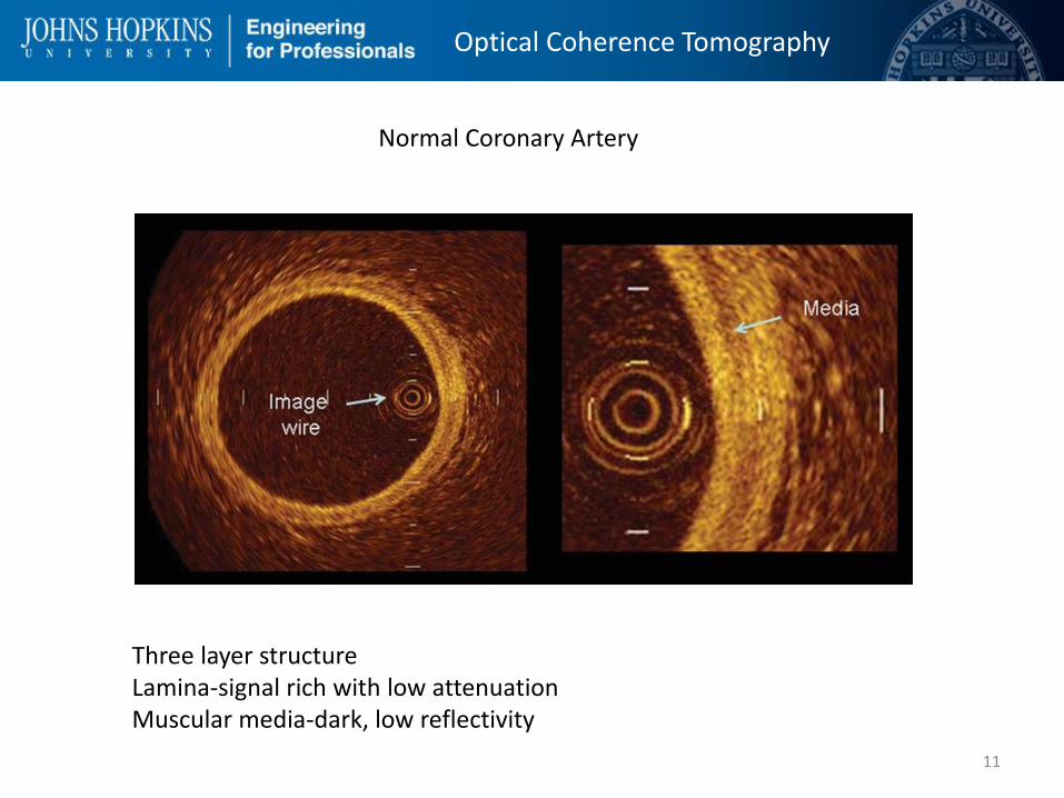
Normal Coronary Artery
Three layer structure Lamina-signal rich with low attenuation Muscular media-dark, low reflectivity
Optical Coherence Tomography
12
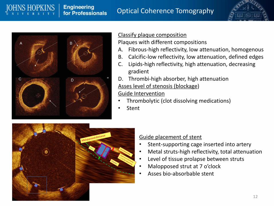
Classify plaque composition Plaques with different compositions A. Fibrous-high reflectivity, low attenuation, homogenous B. Calcific-low reflectivity, low attenuation, defined edges C. Lipids-high reflectivity, high attenuation, decreasing
gradient D. Thrombi-high absorber, high attenuation Asses level of stenosis (blockage) Guide Intervention • Thrombolytic (clot dissolving medications) • Stent
Guide placement of stent • Stent-supporting cage inserted into artery • Metal struts-high reflectivity, total attenuation • Level of tissue prolapse between struts • Malopposed strut at 7 o’clock • Asses bio-absorbable stent

Optical Coherence Tomography
13
Future developments Gray scale image analysis requires experience and time Image post-processing • Color-coding • Real-time 3-D image • Algorithms to characterize composition
Combined OCT and IVUS More precise information on composition and extent of plaque • Leverage OCT detail with IVUS penetration • Combining transducer images difficult • Dual transducer catheter under study OCT and NIRF Microstructure, composition, and molecular processes • Identify areas of inflammation • Assessment of molecular remodeling after intervention • indocyanine green indicator

Optical Coherence Tomography
14
[1] D. Mosaffarian, "Heart Disease and Stroke Statistics-2015 Update," Circulation, vol. 131, pp. e29-e322, 2105.
[2] D. Huang, "Optical Coherence Tomography," Science, vol. 254, no. 22 November, pp. 1178-1181, 1991.
[3] M. Brezinski, G. Tearney, J. Izatt, M. Hee, E. Swanson, J. Southern and G. Fujimoto, "Optical coherence tomography for optical biopsy properties and
demonstration of vascular pathology," Circulation, vol. 93, pp. 1206-1213, 1996. [4]
D. Adler, "Bench to bedside success: intravascular optical coherence tomography," SPIE, 6 September 2012. [Online]. Available:
http://spie.org/x89050.xml?ArticleID=x89050. [Accessed 10 April 2015]. [5]
L. Wang and H.-I. Wu, "Optical Coherence Tomography," in Biomedical Optics, Hoboken, John Wiley & Sons Inc., 2007, p. 185.
[6] R. Hogg and P. Anderson, "Quantum-dot diodes provide sources for optical coherence tomography," SPIE, 1 April 2006. [Online]. Available:
spie.org/x8853.xml. [Accessed 15 April 2015]. [7]
Yuan, "Combining Optical Coherence tomography with fluorescence imaging," in Advances in Lasers and Electro Optics, N. Costa and A. Cartaxo, Eds.,
intechopenbooks, 2010. [8]
B. G. Good, "OPTICAL COHERENCE TOMOGRAPHY/CARDIOLOGY: Totally tubular: Cardiovascular OCT goes prime time," Bio Optics World, vol. 3, no. 4, 01
July 2010. [9]
G. Ferrante, P. Presbitero, R. Whitbourn and P. Barlis, "Current applications of optical coherence tomography for coronary intervention," International
Journal of Cardiology, vol. 165, pp. 7-16, 2013. [1
0] C. Peterson, J. M. Schmitt and J. M. Friedman, "Imaging catheter with integrated reference relector". United States of America Patent US20110007315 A1,
13 January 2011.
[1
1] F. Prati, E. Regar, G. S. Mintz, E. Arbustini, C. Di Mario, J. Ik-Kyung, T. akasaka, M. Costa, G. Guagliumi, E. Grube, Y. Ozaki, F. Pinto and P. W. Serruys, "Expert
document on methodology, terminilogy, and clinical applications of optical coherence tomography: physical principles, methodology of image acquition,
and clinical application for assesment of coronary arteries and atherosclerosis," European Heart Journal, vol. 31, pp. 401-415, 2010. [1
2] H. G. Bezerra, M. A. Costa, G. Guagliumi, A. M. Rollins and D. I. Simon, "Intraconorary Optical coherence tomography: a comprehensive review," JACC
Cardiovascular Interventions, vol. 2, no. 11, pp. 1035-1045, 2009.
[1
3] A. Nair, K. BD, E. Tuzcu, P. Schoenhagen, S. Nissen and V. D. Geoffrey, "Coronary panque classification with intravascular ultrasound radiofrequency data
analysis," Circulation, vol. 106, pp. 2200-2206, 2002.
[1
4] G. Ughi, T. Adriaenssens, W. Desmet and J. D'hooge, "Fully automated three-dimensional visualization of intravascular optical coherence tomography
images: methods and feasablilty in vivo," Biomedical Optics Express, vol. 12, no. 3, pp. 3291-3303, 2012.
[1
5] M. Han, K. Kim, JangS-J and e. al., "GPU-accelerated framework for intraconorary optical coherence tomography at the push of a button," PLoS ONE, vol.
10, no. 4, p. e0124192, 2015.
[1
6] K. Fujii, H. Hao, M. Shibuya, T. Imanaka and M. Fukunaga, "Accuracy of OCT, Grayscale IVUS, and Their Combination for the diagnosis of Coronary TCFA,"
JACC Cardiovascular Imaging, vol. 8, no. 4, pp. 451-460, 2015.
[1
7] J. Li, T. Ma, J. Jing, J. Zhang, P. Patel, K. K. Shung, Q. Zhou and Z. Chen, "Miniture optical coherence tomography-ultrasound probe for automatically
coregistered three-dimensional intraconorary imaging with real-time display," Journal of Biomecical Optics, vol. 18, no. 10, p. 100502, 2013.
[1
8] G. J. Ughi, J. Verjans, A. M. Fard, H. Wang and Osbourn, "Dual modality intravascular optical coherence tomography (OCT) and near-infrared imaging: a
fully automated algorithm for the distance-calibration of NIRF signal intensity for quantitative molecular imaging," The international journal of
cardiovascular imaging, vol. 31, no. 2, pp. 259-268, 2015.
15