Middleware: CORBA & DCOM 1998 Ronald J. Norman, San Diego State University.

East Tennessee State UniversityDigital Commons @ East
Tennessee State University
Electronic Theses and Dissertations
12-2003
Interworking Methodologies for DCOM andCORBA.Edwin KrausEast Tennessee State University
Follow this and additional works at: http://dc.etsu.edu/etd
This Thesis - Open Access is brought to you for free and open access by Digital Commons @ East Tennessee State University. It has been accepted forinclusion in Electronic Theses and Dissertations by an authorized administrator of Digital Commons @ East Tennessee State University. For moreinformation, please contact [email protected].
Recommended CitationKraus, Edwin, "Interworking Methodologies for DCOM and CORBA." (2003). Electronic Theses and Dissertations. Paper 824.http://dc.etsu.edu/etd/824

Interworking Methodologies for DCOM and CORBA
___________________
A thesis
presented to
the faculty of the Department of Computer and Information Science
East Tennessee State University
In partial fulfillment
of the requirements for the degree
Master of Science in Computer and Information Sciences
___________________
by
Edwin Kraus
December 2003
___________________
Dr. Phillip E. Pfeiffer - Chair
Dr. Don Bailes
Dr. Martin L. Barrett
Keywords: COM, DCOM, CORBA, MICO, interworking, distributed computing

2
ABSTRACT
Interworking Methodologies for DCOM and CORBA
by
Edwin Kraus
The DCOM and CORBA standards provide location-transparent access to
network-resident software through language independent object interfaces. Although the
two standards address similar problems, they do so in incompatible ways: DCOM clients
cannot use CORBA objects, and CORBA clients cannot utilize DCOM objects, due to
incompatible object system infrastructures.
This thesis investigates the performance of bridging tools to resolve the
incompatibilities between DCOM and CORBA, in ways that allow clients to cross object
system boundaries. Two kinds of tools were constructed and studied: tools that bind
clients to services at compile time, and tools that support dynamic client-server bindings.
Data developed in the thesis shows that static bridges are on the order of five times faster
than dynamic bridges. Measurements conducted with remote clients also showed that with
increased network delays, performance differences between static and dynamic bridges
become negligible.

3
ACKNOWLEDGEMENTS
First of all I would like to thank Dr. Pfeiffer for his great support, not just for his
help in writing this thesis, but also for his relentless support during the entire course of my
graduate studies. Applying Mr. William Arthur Ward’s classification of teachers: “The
mediocre teacher tells. The good teacher explains. The superior teacher demonstrates. The
great teacher inspires.” ⎯ I must truly say that Dr. Pfeiffer’s teaching style is inspiring.
Many thanks also to Dr. Barrett and Dr. Bailes for their assistance in the thesis
process. I also would like to thank my employer Siemens for their sponsorship, my
colleagues at work for their encouragement, and particularly my supervisor Mr. Ed
Basconi for his patience during my years of study.
Finally, my deepest thanks to my family and friends in Germany, who despite the
distance, provided much needed encouragement and support.

4
CONTENTS
ABSTRACT..........................................................................................................................2
ACKNOWLEDGEMENTS..................................................................................................3
LIST OF FIGURES ..............................................................................................................7
CHAPTER 1 INTRODUCTION ..........................................................................................9
1.1 Thesis Plan ...................................................................................................12
CHAPTER 2 CORBA OVERVIEW ..................................................................................13
2.1 CORBA Objects...........................................................................................14
2.2 Stubs, Skeletons and Servants......................................................................16
2.3 The ORB ......................................................................................................17
2.4 Object References ........................................................................................20
2.5 Object Adapter .............................................................................................24
2.6 MICO Overview...........................................................................................27
2.6.1 The MICO ORB.....................................................................................28
2.6.2 The MICO Runtime Service ..................................................................32
2.6.3 The MICO Implementation Repository .................................................35
2.6.4 The MICO Naming Service ...................................................................37
2.6.5 The MICO Interface Repository ............................................................38
CHAPTER 3 COM/DCOM OVERVIEW..........................................................................40

5
3.1 Interfaces ......................................................................................................41
3.2 COM Objects................................................................................................43
3.2.1 Object References ..................................................................................44
3.2.2 Object Lifetime Management ................................................................45
3.2.3 Object Creation ......................................................................................46
3.3 In-Proc, Out-of-Proc, or Remote Servers.....................................................48
3.4 MIDL Overview...........................................................................................49
CHAPTER 4 BRIDGING CONCEPTS .............................................................................52
4.1 Implementation Strategies............................................................................54
4.2 Bridge Architecture ......................................................................................55
CHAPTER 5 BRIDGE TEST TOOLS...............................................................................57
5.1 Test Object Servers ......................................................................................57
5.1.1 COM Test Object Server .......................................................................57
5.1.1.1 COM Initialization/Termination ...................................................59
5.1.1.2 Server Self-registration/Un-registration........................................59
5.1.1.3 Server Lifetime management ........................................................60
5.1.1.4 Message Loop ...............................................................................61
5.1.1.5 Class Factory Registration/Un-registration...................................61
5.1.1.6 Object Implementation..................................................................62
5.1.2 CORBA Test Object Server...................................................................63
5.1.2.1 ORB Initialization/Termination ....................................................63
5.1.2.2 POA Creation/Initialization...........................................................64
5.1.2.3 Object Creation .............................................................................66

6
5.1.2.4 Object Publishing ..........................................................................67
5.1.2.5 Object Implementation..................................................................68
5.2 Test Clients...................................................................................................68
5.2.1 Early Bound COM Test Client ..............................................................69
5.2.2 Late Bound COM Test Client ................................................................70
5.2.3 Early Bound CORBA Test Client..........................................................73
5.2.4 Late Bound CORBA Test Client ...........................................................74
CHAPTER 6 BRIDGE MODELS ......................................................................................77
6.1 Early Bound Bridge......................................................................................77
6.1.1 COM_CORBA Bridge...........................................................................77
6.1.2 CORBA_COM Bridge...........................................................................79
6.2 Late Bound Bridge .......................................................................................80
6.2.1 COM_CORBA Bridge...........................................................................81
6.2.2 CORBA_COM Bridge...........................................................................83
CHAPTER 7 PERFORMANCE TESTING .......................................................................84
7.1 Test Procedure..............................................................................................85
7.2 Data Analysis and Results............................................................................86
7.2.1 Performance Test Results ......................................................................87
CHAPTER 8 FINAL ASSESMENT AND CONCLUSION..............................................90
APPENDIX A.....COM Test Object Server Class Diagram ..............................................92
APPENDIX B ......CORBA Test Object Server Class Diagram ........................................93

7
APPENDIX C ....COM Early Bound Client Class Diagram ..............................................94
APPENDIX D....CORBA Early Bound Client Class Diagram .........................................95
APPENDIX E ....Early Bound COM_CORBA Bridge Class Diagram ..............................96
APPENDIX F......MIDL Code of the Target COM Object ................................................97
APPENDIX G....Early Bound CORBA_COM Bridge Class Diagram .............................98
APPENDIX H.....IDL Code of the Target CORBA Object ..............................................99
APPENDIX I .....Late Bound COM_CORBA Bridge Class Diagram ............................100
APPENDIX J .....Late Bound CORBA_COM Bridge Class Diagram ............................101
APPENDIX K....Test Data ..............................................................................................102
REFERENCES AND BIBLIOGRAPHY.........................................................................104
VITA.................................................................................................................................106
LIST OF FIGURES
Figure 1 The Object Management Architecture (OMA) [4]...............................................14
Figure 2 Relationship between Stub, Skeleton, and Servant ..............................................17
Figure 3 The Common Object Request Broker Architecture (CORBA)............................18
Figure 4 Structure of an IOR ..............................................................................................21

8
Figure 5 Life Cycle States of a Transient CORBA Object .................................................25
Figure 6 MICO ORB Design Model; adapted from [5]......................................................29
Figure 7 Method Invocation with the MICO ORB.............................................................31
Figure 8 Structure of The MICO Runtime Service.............................................................35
Figure 9 COM Interface Symbology ..................................................................................42
Figure 10 Creation of a COM Object housed in a local server [12] ...................................47
Figure 11 One-way Bridge..................................................................................................53
Figure 12 Two-way Bridge.................................................................................................53
Figure 13 B/A Interworking Model [8] ..............................................................................54
Figure 14 COM/CORBA Bridge - Architectural View ......................................................55
Figure 15 Two-Way CORBA/COM Bridge Model............................................................56
Figure 16 Dual Interface and Dispinterface on a COM object; adapted from [10] ............72
Figure 17 Architectural Model Static COM_CORBA Bridge............................................78
Figure 18 Architectural Model Static CORBA_COM Bridge............................................79
Figure 19 Architectural Model Dynamic COM_CORBA Bridge ......................................81
Figure 20 Architectural Model Dynamic CORBA_COM Bridge ......................................83
Figure 21 Performance Test Plan........................................................................................84
Figure 22 Test Matrix .........................................................................................................85
Figure 23 Test Results Summary........................................................................................86
Figure 24 Bridge Performance Test Results ........................................................................87
Figure 25 Network Communication Delays .......................................................................89

9
CHAPTER 1
INTRODUCTION
Inter-computer communication has been a key area of computer research since
Defense Advanced Research Projects Agency scientists first connected two computers in
1969 [14]. Early research on data communications focused on the reliable transmission of
bits and bytes over distance using guided media. This research, in turn, led to research into
protocols for network communication, including simple, standard protocols for networked
message transmission. One such protocol, the Open Software Foundation’s Distributed
Computing Environment (DCE), was introduced in the early 1990s at a time when
structured procedural programming was the dominant software development model. DCE,
among its other features, supported the use of Remote Procedure Calls (RPC) to invoke
procedures on remote computers as if they were local, and without regard to the details of
the communication infrastructure.
Since 1990, the emergence of object oriented application development has created
a need for more expressive successors to RPC: protocols that allow applications to invoke
not just remote procedures, but procedures associated with specific instances of network-
resident classes. This need was addressed, in one way, by the Object Management
Group’s Object Management Architecture. The Object Management Group (OMG) is a
professional association that develops standards for object-oriented-based distributed
computing. The key standard in the OMG’s Object Management Architecture (OMA) is
the Common Object Request Broker Architecture (CORBA). CORBA defines an

10
infrastructure for enabling communication between the other components of the OMA.
CORBA, like other OMG standards, is a platform independent standard—but, like other
OMG standards, has been deployed primarily on UNIX-like1 systems. This focus on
UNIX is due, in part, to UNIX’s dominance as a platform for distributed computing in the
early 1990’s, when CORBA was originally developed.
While the OMG was developing CORBA, Microsoft, the dominant vendor for PC
operating systems, was developing its own standard for component-based programming.
Microsoft’s Component Object Model (COM) started as a programming model that
supported inter-process communication infrastructure. Later, when desktop PCs were
applied in distributed computing, COM evolved into Distributed COM (DCOM): a
standard that, like CORBA, supports the remote creation and invocation of objects.
The CORBA and DCOM standards address similar problems—and address them
well enough to support the development of a great many diverse applications. Still, the
CORBA and DCOM distributed computing architectures differ in several fundamental
ways. Among the differences are incompatible object models with inconsistent object life
cycle management and a fundamental difference in what objects are.
In order to facilitate interaction between COM- and CORBA-based applications,
the OMG released an interworking specification between COM and CORBA as a part of
its CORBA 2.2 specification. The interworking specification provides a methodology for
enabling communication between objects in DCOM and CORBA, and describes ways for
1 UNIX like systems refers to operating systems that are closely related to the UNIX system developed by K. Thompson and D. M. Ritchie at Bell Labs in 1971

11
objects to access key services in the foreign object system. A key part of this methodology
is a bridge: a vehicle that enables objects from different object systems to communicate.
This thesis analyzes the characteristics of bridge-based DCOM-CORBA
communication. Bridges can be classified into two types, according to when their
endpoints are bound to target objects: early (static) bound bridges, which are compiled
with specific knowledge of the type of object they service; and late (dynamic) bound
bridges, which rely on runtime type information rather than compile time type information
to provide their services. The thesis assesses on how the choice of bridge type, in
conjunction with the degree of communicating object separation, affects communication
performance and flexibility
The work undertaken here was an empirical study. A pair of COM and CORBA
servers, together with a corresponding pair of COM and CORBA clients, were created,
along with two two-way bridges: one static, and one dynamic. Two series of
measurements were then conducted to determine invocation times. One series represents
invocations by collocated clients, the other invocations by remote clients. The results
showed that dynamic bridges are on the order of five times slower than static bridges.
Indications were also present that for remote clients bridge performance differences
become less significant as network latencies increase.
12
1.1 Thesis Plan
The remainder of this manuscript is divided into eight chapters. Chapters two
through three survey background material, including the COM and CORBA object
management systems. Chapter four presents bridging concepts as they apply to this thesis
project, followed by a description of the test tools in chapter five. Chapter six describes
the bridges themselves. Chapters seven and eight conclude by presenting the data and
discussing the study’s results.

13
CHAPTER 2
CORBA OVERVIEW
As object oriented programming paradigms grew in popularity in the late 1980’s,
the need for standards for manipulating distributed objects increased in importance. A
consortium of software vendors, the Object Management Group (OMG), was founded in
1989 to develop standards for object-based distributed computing [15]. The first OMG
draft standard the Object Management Architecture (OMA), was released in 1991.
Since 1991, the OMA has gained considerable popularity. Most people, however,
now refer to this architecture using a name originally bestowed upon that architecture’s
central element: CORBA.
The CORBA portion of the OMA specification describes an infrastructure and
interfaces needed for creating, locating, and invoking operations on objects, distributed
across a heterogeneous environment of host computers and operating systems. The rest of
the OMA is made up of three somewhat blurry categories of interfaces: CORBA Services,
CORBA Facilities and Application Interfaces. Interfaces that apply to all CORBA objects
normally fall in the CORBA Services category and are often referred to as having
horizontal orientation. Domain-specific interfaces (e.g., manufacturing, banking, health
care) are said to have vertical orientation and fall in the category of CORBA Facilities.
The last category of interfaces, Application Interfaces, is specific to a particular CORBA
application. If similar Application Interfaces are used in different applications, over time

14
these interfaces may become part of the CORBA Facilities, as a common need for these
interfaces is recognized.
CORBA Facility C
CORBAServices
CORBA Facility B
Object Request Broker
Application Interfaces
CORBA Facility A
Figure 1 The Object Management Architecture (OMA) [4]
2.1 CORBA Objects
Before the advent of Object Oriented Programming (OOP), procedure-oriented
programming was the dominant model for software development. In 1984, Birrell and
Nelson [13] devised a strategy for procedure-call-based distributed programming, Remote
Procedure Call (RPC), that frames a network send-receive operation as a procedure call
and subsequent return from procedure. RPC simplified distributed computing by shielding
the programmer from the many details involved in calling a procedure that is in a different
address space, or on a different computer.
The more complex OOP model of software development is based on identifiable
groupings of procedures and data known as objects. Objects are constructed in accordance
with principles like encapsulation, hidden implementation of functionality; polymorphism,

15
variation of behavior depending on object type; and inheritance, propagation of attributes
and functionality to child classes.
In the CORBA approach to OOP, programmers use a multipart strategy for
defining a network object. First, a language known as an Interface Definition Language
(IDL) is used to specify an interface for a class of networked objects. IDLs were first
introduced in the context of RPC programming as a necessary tool for location
transparency. The CORBA standard expanded the role of IDLs, morphing them into tools
that enforce the consequent application of object oriented methods, encapsulation,
inheritance and polymorphism. A CORBA-style IDL definition creates a blueprint for an
object. This blueprint serves as a vehicle for informing clients about the makeup and
behavior of an object, and also as a description of a constructed object’s form.
Logically a CORBA object is an instance of a CORBA interface. CORBA
provides the programmer with location-transparent, language-independent networked
objects. Location transparency means that the programmer does not need to specify a
networked code’s location: IDL-created code automatically calls the remote object’s
methods, making it appear as if the remote object resides in the local object’s address
space. Language independence means that the programmer does not have to ensure that a
code that uses an object is written in that object’s native language, so long as both objects
are coded in CORBA-supported languages: the IDL compiler automatically creates the
necessary mappings between method calls and the methods in use.

16
2.2 Stubs, Skeletons and Servants
The CORBA mechanism for supporting location-transparent method invocation
involves substantial behind-the-scenes support and indirection. In part this support is
provided through intermediary entities called Stub and Skeleton objects. A Stub object is
an object that resides in the client’s address space and has an interface identical to the
target CORBA object. Likewise, a Skeleton object resides in the server’s address space,
with the same interface as the target object. The target object, also called a Servant, is the
entity that actually performs operations associated with its interface.
Stub and Skeleton objects are proxy objects in the client and server address spaces.
When a client program invokes an operation on a CORBA object, the work of invocation
begins in the Stub object. The Stub responds to a request for remote invocation by packing
(marshalling) the operation’s parameters into a message, then sending a message, through
mechanisms discussed later, to the Skeleton. The Skeleton then unpacks (unmarshalls) the
message, and invokes the desired operation on the Servant. When the Servant completes
this operation the call returns to the Skeleton object, which marshals the results into a
response, which is returned to the Stub object. The Stub then completes the call by
returning the results to the client program. Before CORBA 3.0 all calls made to CORBA
objects via the Stub/Skeleton mechanism were synchronous. CORBA 3.0 also supports
asynchronous calls
IDL provides the programmer with all the code needed for the Stub and Skeleton
objects. Programmers are left with the task of developing the logic for the Servants, which
represent the meat and potatoes of CORBA objects.

17
Figure 2 shows the relationship between stub objects, skeleton objects and servant
objects.
Stub Object
Client
call foo()
Skeleton Object
Server
Some Object
call foo()
Provided by IDL compiler
Servant made by app. developer
Figure 2 Relationship between Stub, Skeleton, and Servant
2.3 The ORB
The Object Request Broker (ORB), also referred to as CORBA’s object bus, is the
central CORBA element through which objects on the client side and objects on the server
side can communicate. The terms CORBA and ORB are often used synonymously;
however, in this paper the term ORB denotes the ORB core, which acts as the glue that
holds the different CORBA elements together.
Figure 3 shows a graphical representation of CORBA and demonstrates the central
role the ORB plays in the integration of different CORBA elements. What makes the ORB
central to a CORBA system is that the ORB interfaces with all elements of the
architecture, as well as with other ORBs on remote host computers.

18
GIO
P/II
OP
Server Side ORB
Client Side ORB
ORB
Interface Object Adapter
DSI Dynamic Skeleton Interface
IDL Skeleton
IDL Skeleton
ORB
Interface
IDL Stub
IDL Stub DII Dynamic
Invocation Interface
IDL Stub
IDL Skeleton
Interface Repository
Implementation Repository
Language Mapping from IDL
CORBA Standard Interface
GIO
P/II
OP
GIOP/IIOP
ORB Implementation Specific
ObjectReferences
Servant Objects
Figure 3 The Common Object Request Broker Architecture (CORBA)
The communication between ORBs, particularly ORBs from different vendors,
was standardized in CORBA 2.0, with the introduction of the General Inter-ORB Protocol
(GIOP) and the Internet Inter-ORB Protocol (IIOP). GIOP defines the communication
between ORBs in general terms. It describes a Common Data Representation (CDR)
format and message formats for sending requests and responses between ORBs. GIOP
was defined independently of any particular transport protocol in order to accommodate a
wide range of networking infrastructures. IIOP, an Internet-specific implementation of
GIOP, was released at the same time as GIOP. IIOP provides the full-duplex, connection
oriented communication channel that GIOP needs, via the TCP/IP protocol.
Figure 3 shows how client and server applications that reside on different hosts
would use their respective ORBs to communicate via IIOP. A client and server that are

19
co-located on a single host should communicate using more efficient, inner-ORB
communication primitives.
Communication between ORBs and their respective applications involves the use
of one of three CORBA interface mechanisms, according to the communication’s type:
• ORB interfaces support communications between applications and interfaces that are
known to those applications at compile time. These interfaces, known as Static
Invocation Interfaces (SIIs), are invoked implicitly by invocations of Object
References (see next section). They are specific to the server application’s objects.
They are represented by the stub and skeleton procedures discussed earlier.
• CORBA’s Dynamic Invocation Interface (DII) and Dynamic Skeleton Interface (DSI)
support the invocation and implementation of operations for interfaces where the
applications don’t have knowledge of the interfaces at compile time.
• Finally, Object Adapters (OAs) are logical elements that allow an ORB to make the
connection between the abstract notion of a CORBA object and its implementation,
the Servant.
The ORB interface, OA interface, DII and DSI interfaces are defined by the OMG
and published as part of the CORBA standard [8]. The ORB interface is used for ORB
initialization and administrative interactions between applications and ORB.
An ORB’s operation is also supported by CORBA’s Interface and Implementation
Repositories. The Interface Repository is a database that stores the definition of CORBA
interfaces in IDL. The constructs stored in the Interface Repository are equivalent to the

20
IDL code used to generate the static stubs and skeletons. DII and DSI are the primary
users of the Interface Repository.
The Implementation Repository is a storage facility for server entries. ORBs use
this facility to activate servers on demand. When a client invokes an operation on a
CORBA object, the server hosting the object may not be running at the time of the
request. The ORB responsible for the server must determine if the server is already active,
and activate it if it is not, before passing it the request from the client. The Implementation
Repository maintains a table that associates “Server Name” with “Start Command” and
“Activation Mode”. The “Start Command” is executed in order to start a server when
needed. The “Activation Mode” is a qualifier that specifies if a new server instance should
be started for every client or if clients share the services of a single server instance. More
complex features like load balancing are also possible via the Implementation Repository.
2.4 Object References
A CORBA object is an abstract entity that is realized with the aid of a Stub object,
a Skeleton object, a Servant and a wealth of mechanisms to enable these elements to
interact transparently. An object reference, also referred to as Interoperable Object
Reference (IOR), is a representation of a CORBA object that gives a code an ability to
access that object, while hiding the details of that object’s implementation and status.
Ultimately, for the client the only tangible evidence of a CORBA object’s existence is the
IOR that client holds on that object. Semantically an IOR is very similar to an object
pointer in C++. Vinoski and Henning [4] present the following list of features of an IOR.

21
• Every object reference identifies exactly one object instance.
• Several different references can denote the same object.
• References can be nil (point nowhere)
• References can dangle (like C++ pointers that point at deleted objects)
• References are opaque (the client is not allowed to look at their contents)
• References are strongly typed.
• References support late binding.
• References can be persistent.
• References can be interoperable.
In a language with explicit pointers like C++, an IOR is represented in the client’s
address space as a pointer to an instance of a C++ object. Invoking an operation on this
pointer invokes an operation on the CORBA object, which means that the invocation has
to be propagated through Stub, client ORB, server ORB, object adapter, Skeleton and
ultimately to the Servant. An IOR carries all the necessary information in its structure (see
Figure 4) in order for a client call, on an object interface, to find its target.
Type Information Repository ID
EndpointInformation
Object Key
Communication Profile I
EndpointInformation
Object Key
Communication Profile II
………………….
Figure 4 Structure of an IOR

22
The repository ID is a string that identifies an IOR’s type. It can be used for type-
safe downcasting or any other operation that requires knowledge of a CORBA object’s
type. If an ORB implements an Interface Repository, the Repository ID is used as a key to
look up entries in the repository. The OMG has defined three possible formats for the
repository ID: the IDL format, the DCE UUID format, and the Local format. Of these, the
IDL format is by far the most popular. The type of a CORBA object is defined in IDL;
therefore it is the IDL compiler that generates the repository IDs. The repository ID
always corresponds to the most derived type of an IDL interface. For example, the IDL
format of a repository may look like the following:
IDL:Building/Skyscraper:1.0
The IDL source code resulting in the above repository ID would be the following:
module Building {
interface Skyscraper{
};
};
The number 1.0 in the above example is a version ID that is added by the IDL compiler.
Besides the repository ID, an IOR also contains at least one communication
profile. A communication profile stores all information required to locate and establish
communication with an object. If an IOR is to be used with different communication
protocols the IOR contains multiple profiles, one for each protocol. However, most IORs
contain only one profile, a profile for IIOP—the most common protocol in use for
CORBA objects.

23
Because IIOP is based on TCP/IP; it represents endpoint information as an IP
address and a port number. A host name that can be resolved via the Domain Name
System (DNS) may be used in place of an IP address. The endpoint information in a
profile designates either the server that implements the object, or an Implementation
Repository that knows the server’s address. The former is called direct binding; the latter,
indirect binding.
An IOR’s endpoint information allows the ORB to locate the server that
implements an object. Since a server can implement multiple objects, the ORB also needs
additional information that uniquely identifies an object within the server. The additional
information is provided in the object key. The object key is a series of octets that can
contain any information that the server chooses for the identification of an object. This can
range from a string to a Universal Unique Identifier (UUID).
IORs are generated in the servers that implement CORBA objects, and used by
clients to access object operations. From this results the need to distribute IORs from
servers to prospective clients. Currently an IOR can be distributed either by converting it
into a string and sending it via e-mail, or by using a naming or trading service.
A naming service stores associations between an object’s name and its IOR. A
client that knows a naming service’s location and an object’s name can query the naming
service and acquire an IOR. The trading service, which works similarly, stores
associations between object properties and IORs. The client can query for object
references from a trading service not by name, but by object properties.

24
Also noteworthy is the distinction between IORs for transient CORBA objects and
IORs for persistent CORBA objects. IORs for transient CORBA objects reference objects
that become permanently unavailable when a server is shut down. These IORs contain
endpoint information, pointing to the server process that hosts a CORBA object. IORs for
persistent CORBA objects reference objects that can be reactivated on demand. These
IORs contain endpoint information pointing to an Implementation Repository that
activates servers on demand. After server activation, the client is given a new IOR that
points to the server process and is valid until the server is shut down. When the server
becomes unavailable the client falls back to using the persistent IOR.
2.5 Object Adapter
Next to the ORB core, the Object Adapter is the most significant entity in
CORBA—so significant that it is often treated as part of the ORB. Until CORBA version
2.2 the only object adapter in the CORBA specification was the Basic Object Adapter
(BOA). However, omissions in the BOA specifications led the OMG to deprecate the
BOA, replacing it with a new standard, the Portable Object Adapter (POA).
The POA’s main responsibility is to join the interface of a CORBA object,
described in IDL, with its implementation, the Servant. In this regard the POA acts as an
adapter between servants residing in the server and the ORB. POAs also control the life
cycles of CORBA objects and servants. Figure 5 shows the states of a CORBA object
throughout its life cycle. A CORBA object transitions through the individual states during
its life cycle, controlled by POA operations.

25
CORBA’s discipline for separating interface and implementation allows a user to
create a CORBA object without actually providing an implementation at the time of
creation. Two POA operations support object reference creation:
PortableServer::POA::create_reference()
PortableServer::POA::create_reference_with_id().
Either of these operations brings a CORBA object into existence; however, neither
instantiates a servant for the new object.
An object, once created, remains available until its server is shut down. When a
server is shut down, an object that was created by a transient POA ceases to exist
indefinitely. In contrast, an object created by a persistent POA becomes temporarily
unavailable. Figure 5 shows the different states a transient CORBA object assumes in the
course of its life cycle.
Object Non-Existent
Object Exists
Object Activated
Create IOR
Server Down
Create ActiveObject Map Entry
Delete Active ObjectMap Entry
Figure 5 Life Cycle States of a Transient CORBA Object
Whether a POA creates persistent or transient objects depends on the Policies that
a POA was given at the time of its creation. Policies are equivalent to attributes. Prior to
creating a POA, a list of policies is compiled, which is then passed to the POA create
function. Policies, which control a wide range of POA characteristics, include lifespan

26
policies; policies for mapping objects to servants; implicit activation policies; and Object-
ID to servant association policies.
The following sample code shows how to apply policies when creating a POA.
// create persistent lifespan policy;
// Persistent POA's require the -POAImplName comand line parameter to be set
// to the same value as the name of the entry for this server in the implementation repo
PortableServer::LifespanPolicy_var lifespan =
poa->create_lifespan_policy(PortableServer::PERSISTENT);
// create ID assignment policy; default is SYSTEM_ID but we want the user
// to set the object ID; object ID must be unique for the POA
PortableServer::IdAssignmentPolicy_var IDAssignment =
poa->create_id_assignment_policy(PortableServer::USER_ID);
// create empty policy list for new child POA
CORBA::PolicyList policy_list;
// add to policy list
policy_list.length(2);
policy_list[0] = PortableServer::LifespanPolicy::_duplicate(lifespan);
policy_list[1] = PortableServer::IdAssignmentPolicy::_duplicate(IDAssignment);
// create POA
PortableServer::POA_var test_poa = poa->create_POA("TestPOA", poaman, policy_list);
Connecting a CORBA object, represented by its IOR, to its Servant is called
activating the object. A POA maintains a table called an active object map that associates
object IDs with servants. An object ID is part of the object key (see Figure 4) and is
passed to the POA when a client invokes an operation on an IOR.

27
By and large the POA is a quite complex construct encompassing a vast number of
features. This complexity, however, makes the POA very versatile. It gives CORBA the
ability to work with small applications running on embedded systems, as well as with
large systems, that use millions of objects.
2.6 MICO Overview
MICO is the CORBA implementation used for this study. The name MICO [2]
stands for MICO Is CORBA, following a naming schema introduced by the Free Software
Foundation (FSF) for naming the GNU (GNU’s not Unix) project. In the spirit of the FSF,
MICO is distributed as free software under the GNU public license.
MICO is one of several widely known open source CORBA implementations.
MICO was chosen for this study because it easy to learn and highly modular—i.e.,
capable of supporting emerging features of the CORBA specification.
A partial list of features in MICO 2.3.7, the version used for this study, reads as
follows:
• IDL to C++ mapping
• Dynamic Invocation Interface (DII)
• Dynamic Skeleton Interface (DSI)
• Interface Repository (IR)
• IIOP as native protocol (ORB prepared for multi-protocol support)

28
• Portable Object Adapter (POA)
• Objects by Value (OBV)
• CORBA Components (CCM)
• Dynamic Any
• Interceptors
• Support for secure communication and authentication using SSL
• Support for nested method invocations
• Implementation Repository
• Interoperable Naming service
• Trading service
• Event service
2.6.1 The MICO ORB
The design of the MICO ORB [5] is based on the micro-kernel approach to
operating systems design. The ORB core provides only the most basic functionality
required of an ORB:
• Relaying of method invocations
• Bootstrapping
• Support for the creation of IORs

29
Relaying of method invocations is the primary function of an ORB. The MICO
designers placed great emphasis on generalizing this function in the ORB. They
interjected intermediary objects between applications and the ORB core to achieve
maximum generalization of the ORB core. These intermediary objects implement standard
CORBA interfaces on the application side, and they use the generalized interfaces on the
ORB side. From the ORB’s point of view, the intermediary objects fall into two
categories: request objects and execution objects. Request objects generate method
invocation requests; execution objects process these requests. The ORB implements an
interface for each of the two categories of intermediary objects–a method invocation
interface, and a method execution interface.
CORBA request objects are typically called “Stub” objects. Applications interact
with stub objects either through the SII or DII interface. Requests originate in client
applications and are forwarded by the stub objects to the ORB core via the ORB’s method
invocation interface.
ORB Core Method Invocation Interface Method Execution Interface
Request Objects Execution Objects
Applications
SII
Object
DII
Object IIOP
Object IIOP
Object DSI
Object
SSI
Object
Figure 6 MICO ORB Design Model; adapted from [5]

30
The ORB core relays requests generated through its method invocation interface to
the appropriate execution object, using its method execution interface. Execution objects
are called “Skeleton” objects in CORBA. Skeleton objects interact with server
applications either via the DSI interface or the SSI interface. Skeleton objects, like Stub
objects, forward requests to server applications, which ultimately perform the requested
services.
The IIOP object shown in Figure 6 plays a dual role, as either a request object or
as an execution object. IIOP objects are communication objects that simply forward and
also receive invocations; applications don’t interact with these objects directly. When an
ORB cannot find a local execution object to satisfy a request, it uses an IIOP object to
forward the request to a remote ORB. In the missing object scenario, each ORB, the local
and the remote ORB, uses an IIOP object for communication. The local ORB uses an
IIOP object in the role of an execution object, whereas the remote ORB uses an IIOP
object in the role of a request object.
Through the use of generically defined, ORB specific interfaces, the MICO ORB
allows object adapters or transport objects to be changed without changing the ORB core
itself.

31
ORB A
Invocation Interface
DII
IDL Stub
IIOP Transport
Object
Execution Interface
Object Adapter
DSI
IDL Skel.
IIOPTransport
Object
ORB B
Invocation Interface
DII
IDL Stub
IIOPTransport
Object
Execution Interface
Object Adapter
DSI
IDL Skel.
IIOP Transport
Object
Client
Remote Server
Language Mapping from IDL CORBA Standard Interface ORB Implementation Specific
Local Server
Figure 7 Method Invocation with the MICO ORB
Bootstrapping, the second most important task of an ORB core, is the ability of an
ORB to give a CORBA application the ability to acquire an object reference. It is
generally thought that bootstrapping is accomplished with the aid of a naming service or a
trading service. However, before a naming service can supply IORs, an IOR to the name
service itself must be acquired first. For this purpose, the MICO ORB implements the
MICO binder, an ORB internal minimal naming service. Using the MICO binder, the
ORB can obtain IORs for several key services at startup. To use the binder, the ORB must
provide a tuple of locator, object ID, and type ID.
Applications may request IORs for key services from the ORB by calling
resolve_initial_references(). This function is provided as part of the OMG-standard ORB
interface. In order for calls to resolve_initial_references() to succeed, the ORB must be
told at startup what the locators are, to be used in finding objects that implement CORBA

32
services. The CORBA specification defines rules for passing command line arguments to
the ORB, which enable the ORB to implement bootstrapping.
Per the CORBA specification, every CORBA server must initialize the ORB by
calling CORBA::ORB_init() upon startup. The initialization function receives the
application’s command line parameters for parsing of ORB parameters. ORB parameters
are of the form “–ORB[ParameterName] [ParmeterValue]”. The ORB removes its
parameters before returning the command line to the application. One of these command-
line parameters, “-ORBIIOPAddr”, specifies the port that the MICO ORB’s IIOP server
uses to listen for requests. Other ORB parameters include the IP addresses of CORBA
services objects, like Interface Repository, Implementation Repository, and Naming
Service
Finally, the MICO ORB supports the creation of IORs through a template. IIOP
transport objects contribute the communication endpoint information to the template.
Object adapters request the template from the ORB every time an IOR must be created, as
they bear the responsibility of creating IORs.
2.6.2 The MICO Runtime Service
A CORBA client application that requires the services of a particular CORBA
object must use an IOR to access those services. To obtain an IOR the client may use a
CORBA naming or trading service. MICO’s implementation of CORBA’s naming service
is described later in this document.

33
Once in possession of an IOR a CORBA client makes calls to the object,
completely unaware if the server is running or not. Ensuring that a server is running when
calls are made to its objects is the responsibility of the MICO runtime service. A runtime
service is a process that is started when its host is powered up. In a Unix environment
these background processes are known as daemons; in Windows they are referred to as
services. A single CORBA implementation may actually use multiple daemons for
different CORBA services.
MICO’s primary daemon process (micod.exe) contains a mediator object that
works closely with the MICO Implementation Repository to start servers on demand. The
mediator object intercepts a client’s first call to an IOR and starts the server process on the
client’s behalf. However, this is only possible if an entry for the server is found in the
Implementation Repository.
In order for the mediator to be able to intercept calls between client and server, the
IOR the client uses must contain the endpoint information for the mediator object—and
not, more specifically, for the CORBA object it targets. This type of IOR is created by a
POA with the persistent lifespan policy. When an IOR is created by a persistent POA, the
mediator process’s endpoint information is placed into the IOR instead of the endpoint
information of the CORBA objects process. Consequently a call made with such an IOR
results in a call that is redirected to the mediator object.
The mediator maintains a list of active servers, which is consulted every time a call
arrives from a client. If the mediator determines that the requested server is not currently
running, it automatically starts the server. Once activated the server informs the mediator

34
of its readiness, and also conveys its endpoint information to the mediator. The mediator
then creates a new IOR for the client, this time placing the CORBA server’s address in the
IOR. The new IOR is then returned to the client in an IIOP forward message. With the
new IOR the client can contact the server directly and invoke the operations it requires.
All of this indirection activity is performed transparently to the client.
The approach described above for bringing server and client together is referred to
as indirect binding. The alternative method is direct binding. Direct binding requires a
server to run permanently. Since this is not possible, a method is required for sending an
IOR to the client every time a server restarts. With indirect binding, persistent CORBA
objects become possible. IORs to persistent objects remain valid when a server is shut
down, and servers can be moved to different hosts without breaking existing IORs. The
main drawback of indirect binding is that the first call a client makes takes slightly longer
to complete than if the first IOR would have contained the server’s address directly.

35
Client
ORB
Server
ORB
Host Process (micod.exe)
1
3 4
6
57
8
Server Activation Sequence
1) Client makes a call on a persistent IOR
2) Mediator checks its list of active servers to see if the requested server is already active.
3) If the server cannot be found in the active server list, the mediator looks up a record for this server in the implementation repository.
4) The implementation repository stores the records for registered servers. It returns the record for a server to the mediator upon request.
5) The mediator starts the server with a command string received from the repository.
6) The server returns its communication endpoint information to the mediator.
7) The mediator constructs a new IOR and returns it to the client.
8) The client uses the new IOR to communicate with the server without intervention from the mediator as long as the server is active.
ImplementationRepository
Mediator 2
ORB
Administrative Client
(imr.exe)
ORB
Figure 8 Structure of The MICO Runtime Service
2.6.3 The MICO Implementation Repository
According to Henning and Vinoski [4] a CORBA Implementation Repository is
responsible for all the functions described in the previous section, “The MICO Runtime
Service”. However, the MICO documentation characterizes the Implementation
Repository as a repository of server records, which provides information to the ORB
daemon process.

36
Each record in the MICO Implementation Repository contains the following
information:
• A server name
• The server activation mode (persistent; shared; unshared; per method; library; poa)
• The server activation command
• A list of objects hosted by the server
The following is an example of a record in the MICO repository:
server name: TestServer
activation mode: poa
activation command: D:\CORBA\TestServer\Debug\TestServer.exe
object #0: IDL:IPort:1.0
In this record, the server name uniquely identifies a server in the Repository.
The activation mode specifies how and when a new server process should be
started. An entry of “persistent” for the activation mode means that the server is started by
some other means than the ORB daemon. A server started as “shared” only needs to be
started once as all clients share the same server. In the case of an “unshared” server, a new
server instance must be started for every client. With “per method” servers a new server
instance must be started for every operation invocation on an object in the server.
“Library” servers are servers implemented through a dynamic link library and are
therefore linked directly into the client process.
Another specialty of the MICO Implementation Repository is the activation mode
“poa”. The MICO daemon process uses two types of mediators for activating servers. One

37
type activates BOA based servers, and the other POA based servers. The activation mode
“poa” makes the POA mediator responsible for server activation, which starts the server
as shared.
The server activation command contains the command line string for starting the
server. This command line string may contain any parameters that need to be passed to the
server upon startup.
The record’s last field lists object types hosted by the server. The object types are
expressed by Interface Repository IDs.
For administrative purposes, MICO provides a program called imr. This program
registers and un-registers servers with the repository. It also provides listing and forced
activation capabilities.
2.6.4 The MICO Naming Service
CORBA naming services allow CORBA clients to use an object’s name to
discover that object’s location. A naming service stores name-to-IOR associations called
name bindings in a hierarchical structure whose nodes are referred to as naming contexts.
Each naming context is an object containing a table of name bindings. The total construct
resulting from this abstraction is called a naming graph [9].
MICO implements its CORBA naming service through a daemon process called
nsd, and an administration tool called nsadmin. Nsd is configured at startup via command
line parameters to listen on the desired TCP port for client requests. Likewise the clients
are given the naming service’s address as a command line parameter at startup.

38
A naming service stores object bindings, which are associations between names
and object references. Object bindings are stored in a hierarchical tree like structure, very
similar to the structure of a file system. The nodes of this structure are called contexts and
the leaves are the object references.
The names clients use to denote an object are compound names consisting of an id
field and a kind field. This makes the syntax of a name in string format somewhat
cumbersome. However, the kind field can be omitted when not in use, which happens
fairly often. To fully qualify an object reference, a string containing naming contexts from
the root of the tree to the object name—a notation similar to a file system designation—
can be used. The following is an example of an object name:
root_context/node_context1/node_context2/object_name
The OMG naming service specification describes in great detail the exact
representation of object names as strings, including the use of escapes for the “/” character
and the representation of a string’s kind field.
2.6.5 The MICO Interface Repository
The Interface Repository stores interface definitions, which are equivalent to the
interface definitions stored in IDL files. The Interface Repository enables processes that
have an incomplete understanding of an object at compile time to access that object via
dynamic invocation. The IR is most often used with the Dynamic Invocation Interface
(DII) and Dynamic Skeleton Interface (DSI) to discover the parameters and parameter

39
types of interface operations at run-time. With this information, the data can be marshaled
for transport across ORB boundaries, and also across object system boundaries.
The Interface Repository is itself implemented as a CORBA object. In MICO the
server that hosts the Interface Repository is called ird. Ird is configured at startup through
a command line parameter to listen on the desired TCP port for client requests. The same
mechanism is used to convey to the client on what port ird is listening.
Information is entered into the Interface Repository through the MICO IDL
compiler. This use of the IDL compiler to feed idl files into the repository is an obvious
implementation decision, since IDL compilers are designed to interpret idl files. The
compiler can also re-create idl files from the information in the Interface Repository.
The following is an example of a command that feeds an idl file into a repository:
idl --feed-ir --no-codegen-c++ filename.idl
The parameter “--no-codegen-c++“ suppresses the creation of language mapping
files for C++. The reverse for the previous operation is as follows:
idl --repo-id=IDL:InterfaceName:1.0 --no-codegen-c++ --codegen-idl --name=FileName
The command above extracts the information for the interface specified by a
repository ID, and creates the idl file specified by the name parameter.
The Interface Repository stores information on interfaces in hierarchical
groupings. At the top of the hierarchy are CORBA modules.

40
CHAPTER 3
COM/DCOM OVERVIEW
The idea at the root of COM is to break up monolithic applications into smaller,
more manageable components2. A monolithic application is understood as a compiled and
linked unit of code that is distributed to end-users. The problem with monolithic
applications is that they are difficult to maintain. To counteract aging and obsolescence,
applications must continuously be updated with newer code. By building applications
from discrete components, the upgrading process can be simplified to replacing only the
out of date components as opposed to the entire application.
The concepts behind COM seem very much inspired by the concepts of object-
oriented programming, with only the motivation and problem domain being somewhat
different. Microsoft saw component based application development as a means of
overcoming problems related to the realities of application development, distribution, and
maintenance.
One cornerstone of COM, as well as object oriented programming, is the notion of
encapsulation. According to Rogerson [10], the concept of encapsulation places the
following constraints on components:
• A component must hide the programming language used for its implementation, to
enable any client written in any language to use the component.

41
• A component must be transparently relocatable on a network, to avoid breaking
clients when a component is moved to a new location
The balance of this chapter describes how the COM design supports these
constraints. Not surprisingly, many of COM’s architectural features have direct
counterparts in the CORBA framework.
3.1 Interfaces
An interface, as it is understood in COM, describes the behavior of a software
component. An interface specification can be likened to a contract between a component
and its clients, whereby the component trades the right to change existing interfaces for
the certainty that it will always be able to communicate with correctly designed clients. If
the need arises to modify an existing component, new interfaces may be added to it, but
old interfaces must also be kept intact, because COM interfaces are defined as immutable.
At the functional level, interfaces are groupings of related methods, defined in a
meta language called MIDL (Microsoft Interface Definition Language). MIDL is used to
describe the interfaces in terms of their operations, operation parameters, operation return
types, and interface identifier.
At the lowest level, the binary level, interfaces are list structures of pointers to
functions. The COM runtime library uses these function pointers to invoke the operations
of an interface on behalf of a client. The COM documentation specifies interfaces at this
2 Components are self-contained units of code with a well-defined method of access.

42
lowest level to allow the use of any programming language, capable of producing the
structures of function pointers described by COM, for component development that is.
Apart from defining the structure of interfaces, the COM specification also defines
a set of standard interfaces. Standard interfaces describe essential operations, which form
the backbone of the infrastructure for component lifetime management, interface
discovery, and many other essential services. In many respects, standard interfaces have
the same purpose as services and facilities in CORBA. IUnknown is the one standard
interface all other interfaces must inherit from in order to be considered COM interfaces.
Interface inheritance is the commonly employed method in COM programming to extend
or modify the behavior of an interface. The COM specification recommends a graphical
notation format, which depicts interfaces as circles or jacks (see Figure 9), for clients to
plug into the components.
ComponentClient
CustomInterfaces
StandardInterfaces
Figure 9 COM Interface Symbology
COM interfaces are sometimes classified as Custom or Automation interfaces.
This nomenclature refers to an interface’s ability to support different programming
languages. Although COM is a binary interface standard, and therefore independent of
syntactic standards, scripting languages like VB Script or Java Script lack the capability to

43
access the binaries that define an interface. To enable these languages to use COM
components, developers may choose to support a standard COM interface called
IDispatch. This interface is commonly known as the Automation interface. The IDispatch
interface provides scripting languages and other languages that don’t support direct access
to function pointer tables with the ability to use COM components. Essentially, IDispatch
binds components to callable procedures at runtime, thereby trading speed of access for
ease of use.
Languages that support the use and creation of custom interfaces include C, C++
and recent versions of VB. VB can now read and interpret type library files (*.tlb files),
which are a binary representation of the interfaces supported by a particular component.
3.2 COM Objects
Interfaces, rather than objects, are the key conceptual element in COM. A COM
object—also known as a COM component, or coclass—is a kind of secondary element
that serves as a concentrator for a set of interfaces.
A COM object’s identity is established through a globally unique identifier
(GUID). GUIDs are system-generated names that, supposedly, are generated in ways that
prevent their reuse after generation. GUIDs identify several kinds of COM entities: a
GUID that identifies a COM object is also known as class ID (CLSID).
COM also supports a second type identifier for COM objects. These identifiers,
known as programmatic identifiers (ProgIDs), are easier to read than CLSIDs—but they

44
are not guaranteed to be unique in time and space. COM supports mapping operations
between ProgIDs and CLSIDs.
3.2.1 Object References
COM does not directly support the notion of an object reference, or the use of
references to access COM codes. The entity in the COM standard that most closely
resembles an object reference is a COM interface pointer. A COM interface pointer is
essentially a pointer to a table of function pointers that corresponds to a particular
interface. In contrast to CORBA object references COM interface pointers are simply
references to memory structures in the client process. The memory structures pointed to
are responsible for establishing the link to the interface implementation. CORBA
references have more semantic depth in that they themselves represent the link to the
object implementation.
To acquire interface pointers, clients use the one standard interface, which is
implemented on all COM objects and is known as IUnknown. IUnknown is defined in
MIDL by the COM specification as follows:
[local, object, uuid(00000000-0000-0000-C000-000000000046),
pointer_default(unique)]
interface IUnknown
{
HRESULT QueryInterface(
[in] REFIID riid, [out, iid_is(riid)] void **ppvObject );
ULONG AddRef();
ULONG Release();
}

45
TheAddRef() and Release() functions, which support object lifetime management,
are discussed later. The remaining function, QueryInterface(), takes two parameters: an
interface identifier and a variable that serves as placeholder for the corresponding
interface pointer. Interfaces identifiers are GUIDs and are usually referred to as IIDs.
When called, the implementation of QueryInterface() looks for a match on the requested
IID. If one is found, the corresponding interface pointer is returned.
Since all COM interfaces inherit from IUnknown, QueryInterface() can be called
from any interface pointer. Consequently a client can navigate from any interface of an
object to any other interface of that object.
3.2.2 Object Lifetime Management
Unlike in CORBA, where object lifetime is distinct from object server lifetime, the
lifetime management of COM objects is closely related to the lifetime management of the
component server. Details related to COM component servers are discussed in following
sections. The end of life determination for COM objects relies on a technique known as
reference counting. The reference counting mechanism is implemented through the
IUnknown interface.
Two of the three operations described in IUnknown, AddRef() and Release(),
support interface reference counting. The reference count for an interface must be
incremented when an interface is acquired, and the reference count must be decremented
when the use of an interface is no longer required. Several exceptions to these rules make
reference counting error prone despite its simplicity. For example, functions that return

46
interface pointers are responsible for incrementing that interface’s reference count, and
leave the caller responsible for calling the Release() function.
When the reference counts of all interfaces of a COM object reach zero, the object
is released from memory. The notion of a persistent object, as supported by CORBA, is
non-existent in COM. COM object references or interface pointers always become
permanently invalid when the object server is shut down. However, COM does provide a
mechanism for persisting object state with the aid of special components called Monikers.
3.2.3 Object Creation
COM objects are created through the use of a COM runtime entity called the
Service Control Manager (SCM), and a type of COM component known as a class
factory. COM clients as well as COM servers interact with the SCM through an SCM
API. The SCM’s role is similar to the role of a CORBA ORB, and the API used by COM
applications is semantically similar to the ORB interface.
Class factories, otherwise known as class objects, are special COM components
that implement an interface called IClassFactory (as a COM object, a class factory must of
course implement IUnknown as well). The IClassFactory interface defines two methods,
CreateInstance() and LockServer(). CreateInstance() implements the knowledge of how to
create an instance of a specific type of COM object, and LockServer() is used for server
lifetime management, and is described later.
The process of creating a COM object begins with a call from the COM client to
the SCM’s CoGetClassObject() method . CoGetClassObject() is given a CLSID that is

47
used to locate and activate the class factory for the requested COM object.
CoGetClassObject() returns an IClassFactory interface pointer. The client uses the
IClassFactory pointer to call CreateInstance() to create the COM object it desires.
Class factories are implemented by the component developers, and are normally
housed in the same server as the components themselves. Therefore, the SCM must locate
and activate the component server before it can create a class factory. The directory for
COM objects is the Windows registry, which is where the SCM looks for the executables
for component servers. Figure 10 shows the sequence of steps required to create a COM
object housed in an out of process server.
COM ObjectOr CoClass
Class ObjectOr
Class Factory
EXE Housing
WinMain CoInitialize Create class factory CoRegisterClassObject returning IClassFactory
CoGetClassObject Look up CLSID in registry Look up EXE for CLSID Launch EXE Return Class Factory pointer to client
COM
CoInitialize Call CoGetClassObject CreateInstance()
Use object
Client
1
5
2
4
IClassFactory 6
8
9
3
7
Figure 10 Creation of a COM Object housed in a local server [12]
Objects created with CoGetClassObject() are usually in the same initial state after
each startup, because CoGetClassObject() does not support the notion of object
persistence. COM facilitates object persistence through components that implement the

48
standard interface IMoniker, and are therefore simply called Monikers. Monikers are a
type of factory component that create a COM component, and restore it to a previous state
on the client’s behalf. The responsibility of implementing the code for state persistence
lies with the component itself. By implementing the standard COM interface IPersist, the
objects state can be persisted and restored by the client via the components Moniker.
3.3 In-Proc, Out-of-Proc, or Remote Servers
COM interfaces are implemented by creating a software component that behaves
according to the interface’s specifications. It can therefore be said that interfaces exist in
the context of the components that implement them. The components themselves also
need an environment in which to exist. This environment is usually a Dynamic Link
Library (DLL) or an executable file (EXE). In COM terminology it is said that DLLs and
EXEs are component housings. The term “Server” typically designates a component
housing in COM.
The precise relationship between servers and clients varies according to the degree
to which they are separated. A server that executes on a different host from its client is
known as a remote server. A server that executes on the same host as its client but in
different processes is known as an out-of-process server or local server. A server that
executes in the same process as its client, is known as an in-process server.
Remote and out-of-process servers are implemented as EXEs. When executed,
they reside in their own processes. In-process servers are implemented as DLLs: blocks of

49
code that are loaded into the calling process and that share the process’s resources with the
caller.
A server’s behavior does not necessarily depend on whether it is implemented as
remote, in-proc, or out-of-proc. However, the degree of separation between client and
server affects server response time. In-proc servers can be accessed through simple
function calls, which take micro seconds to perform. To access an out-of-proc server, a
client utilizes local procedure calls (LPC), which can take milliseconds to complete.
Accessing a remote server is the most time consuming of all. Transmitting messages
across a network can take seconds or even minutes, depending on network traffic. The
server’s intended application must be considered when determining its implementation.
For this study, COM servers are implemented as out-of-proc servers, primarily because
the code for an out-of-proc server and a remote server is identical and the transition from
one to the other is relatively easy.
The degree of separation between client and server also affects process robustness.
Out-of-proc and remote servers are more stable than in-proc servers. The crash of an out-
of-proc or remote server process should not produce a corresponding crash of the
corresopnding client process. From the server’s perspective, a misbehaved client cannot
take down the entire server and disturb the operation of other clients.
3.4 MIDL Overview
The Microsoft Interface Definition Language (MIDL) is based in large part on the
IDL developed by the OSF. An interface definition language’s main purpose is to provide

50
developers with a tool for describing interfaces, their operations, and parameters. Since
MIDL is just a metalanguage for describing interfaces, it cannot be used to write interface
implementations.
MIDL and its associated compiler simplify the work of component development
by generating all the support code needed to invoke remote objects. Without the
metalanguage all the support code would have to be provided by the developer. This
support code enables clients to make calls to objects located outside their address space, in
the same way as they would make calls to objects in their own address space.
MIDL is not directly compatible with IDL due to Microsoft’s modifications to fit
the COM specification. One notable difference between the standards is MIDL’s use of
braces ([ ]) to flag the MIDL keyword following an attribute. Another is MIDL’s support
for Microsoft type libraries: files that contain binary representations of the components
and interfaces defined in MIDL. Programmers reference these files from languages used
for component development, or client development in order to discover interface syntax
for components.
When a file containing MIDL code is compiled, the compiler produces a number
of mapping files from MIDL to C++. The following is a full list of files generated by the
MIDL compiler:
• A C++ header file (*.h)
• C++ code files with GUIDs (*.c)
• A binary representation of the interface definitions (*.tlb)

51
• Stub and proxy code for marshalling (*_p.c)
• Definitions to build the stub and proxy DLL (dlldata.c)
The files generated by the MIDL compiler provide the means for marshalling calls
between client and server. Marshalling is the mechanism through which function calls are
packaged and relayed from the client process to the server process. Similar to the stub and
skeleton objects used by CORBA, COM uses proxy and stub objects for the same
purpose.

52
CHAPTER 4
BRIDGING CONCEPTS
In many respects COM and CORBA are similar. They both, for example, provide
infrastructures for object distribution, a language for describing access to objects, and
object directories. Yet there are numerous details in their implementations that make
COM and CORBA objects incompatible: COM clients cannot make direct use of CORBA
objects, and CORBA clients cannot access COM objects.
These incompatibilities between COM and CORBA can be resolved through the
use of a bridge. A bridge allows a client of one object system to access objects of a
different object system, by making the necessary conversions between object access
protocols. Bridges resemble COM proxy objects and CORBA proxy objects in their use of
marshalling function calls between client and server to disguise these conversions. In
addition to parameter marshalling and call forwarding, bridging objects must also map the
identities and life cycle models of the different object systems.
Bridges can be one-way or two-way. One-way bridges enable clients in object
system A to access objects in object system B (see Figure 11) but the reverse is not
possible. Two-way bridges enable clients in both object systems to access objects in the
respective other object system (see Figure 12). An implementation of a two-way bridge
would have to consist of two generic bridge objects. One bridge object would map COM
objects to CORBA clients, and the other would map CORBA objects to COM clients.

53
Object System A
ClientOne-Way
Bridge
Object System B
Object
Figure 11 One-way Bridge
Object System A
Client
Two-WayBridge
Object
Object System B
Client
Object
Figure 12 Two-way Bridge
The CORBA interworking specification uses the terms “view of A in B” and “A/B
view” to refer to the entities representing an object of object system A to a client in object
system B; e.g. a CORBA object visible to a COM client would be called a CORBA/COM
view. Figure 13 shows the interworking model as it is defined in the CORBA specification
[8]. The bridge object holds a reference to a target object in B and maps this reference to a
reference in A. A client in object system A can use the reference exposed by the bridge
object and make calls on the object in B.

54
Object System A Object System B
Target objectimplementation
in B
View of target in B(bridging object)
Bridge
ObjectReference in B
ObjectReference in A
Figure 13 B/A Interworking Model [8]
4.1 Implementation Strategies
COM proxy objects and CORBA stub objects—hereafter referred to as proxy
objects, for simplicity—can be implemented as either early bound or late bound objects.
Early bound proxies are created by the IDL (or MIDL) compiler, and are sometimes
referred to as static or interface-specific proxies. Late bound proxies are generic proxies
that can be used for mapping any object and interface, and are sometimes referred to as
dynamic proxies.
The main reason for using early bound proxies to implement bridges is
performance. Since the operations and operation signatures of an early bound proxy are
known at compile time, early bound proxies have less run-time overhead than late-bound
proxies. In order to implement an early bound bridge, separate bridge objects must be
constructed for every distinct pair of objects to be bridged. These bridge objects can be
constructed manually, or using a compiler that generates the bridge objects from IDL

55
code. Building two-way bridges between CORBA and COM would require a compiler
that could compile both IDL and MIDL code.
The main reason for using late bound proxies to implement bridges is flexibility.
Late-bound bridges can be used to invoke any type of object at any point in a program’s
operation. However, late bound bridges, like late bound proxies, still need to process
target interfaces to satisfy requests. Late bound bridges, like late bound proxies, use a
repository to examine the operations and operation signatures of a requested interface at
runtime. Using these signatures, a bridge can perform the required parameter conversions
at the time of the call. The examination of operation signatures and marshalling of
parameters is a time consuming process, thus making late bound bridges uniformly slower
than early bound bridges.
4.2 Bridge Architecture
To conduct the research for this study, two two-way bridges were developed: one
based on early binding, and the other on late. Both bridges have the architecture depicted
in Figure 14.
CORBA Client
COM Server CORBA Server
COM/CORBABridge
COM Client
DCOM
DCOM
DCOM
GIOP
GIOP
GIOP
Figure 14 COM/CORBA Bridge - Architectural View

56
The COM client in Figure 14 communicates with the COM server using DCOM
protocols, and the CORBA server using the COM/CORBA Bridge. The bridge translates
from DCOM to GIOP communication, as required by the CORBA standard. Similarly the
CORBA client may communicate with the CORBA server using the CORBA native GIOP
protocol, or with the COM server using the translation service provided by the bridge.
Internally the bridge receives calls with the server object, and forwards the calls to its
internal client object, which then dispatches the calls to the server in the target object
system.
CO
RB
A_C
OM
Brid
ge COMServer Object
CORBAClient Object
COM Client
CORBA Server
CO
M_C
OR
BA
Bridge
COMClient Object
CORBAServer Object
COM Server
CORBA Client
CO
MC
OR
BA
CO
MC
OR
BA
Figure 15 Two-Way CORBA/COM Bridge Model

57
CHAPTER 5
BRIDGE TEST TOOLS
In addition to the bridges, the work described in this thesis included the creation
of codes for testing the bridges. These codes included early-bound and late-bound
versions of CORBA and COM server and client tasks (see Figure 15).
5.1 Test Object Servers
The test object servers are the containers that house the test objects. For each
object system one object server was built: a simple calculator object that supports one
interface, the BasicMath interface, with a single function, Add(). Add() accepts two in
parameters and returns an out parameter: the addition’s result.
A server’s code, regardless for which object system, has two main purposes:
• Bootstrapping and communication with the object system controller
• Implementation of objects
Both of these aspects of an object server are significantly different for COM and CORBA.
The balance of this section describes the implementation of the COM and CORBA test
object servers.
5.1.1 COM Test Object Server
A COM server’s bootstrap code depends on the type of COM server. As
mentioned earlier, a COM server is either an in-process server, an out-of-process server,

58
or a remote server. The COM nomenclature is somewhat confusing, since out-of-process
and remote servers are identical with respect to the server implementation. The two kinds
of servers do, however, vary from the viewpoint of the object system controller. An out-
of-process server may run as a local server—i.e., on the same host as the client —or a
remote server—i.e., on a different host. The two kinds of servers use the same executable
file format. All COM servers used in this thesis are out-of-process servers, which is why
only the bootstrapping for an out-of-process server is discussed.
The task of bootstrapping and communication with the object system controller
can be further subdivided into the following sub-tasks:
• COM initialization/termination
• Server self-registration/un-registration
• Lifetime management
• Message loop
• Class factory registration/un-registration
The COM object test server implements the concepts and requirements presented
in the following section with the classes shown in the class diagram in Appendix A. All
operations for bootstrapping described in the following sections, are implemented in the
HousingManagerClass, the ExeHousingManagerClass, the COMFactoryClass, and the
CalculatorFactoryClass.

59
5.1.1.1 COM Initialization/Termination
When the executable file of a COM server is first loaded into memory and starts
executing, it is just another process running on a host. This process becomes a COM
server when it starts communicating with the COM object system controller. The object
system controller in COM is called the Service Control Manager (SCM). COM provides
developers with an API for communication with the SCM contained in the dynamic link
library OLE32.DLL. The first call a process must make to announce itself to the SCM is
CoInitialize(). CoInitialize() initializes the COM library for use by the current process.
Any other calls to the COM library before calling CoInitialize() result in error conditions.
To announce the termination of a COM process to the SCM the function CoUnitialize().
5.1.1.2 Server Self-registration/Un-registration
In order for the SCM to activate a COM object, the SCM must first locate and
activate the server that houses the requested object. The information regarding the server
for a specific COM object is stored in the Windows Registry. The SCM locates objects in
the Windows Registry based on their CLSID.
Entering the information related to a COM object into the registry is the object
developer’s responsibility. The information can be entered into the registry in several
ways. Distributing a *.reg file and merging it into the registry upon installation is one way
of registering a server. Another method is the use of a script resource written in registry
script language, as provided by the Visual Studio Environment. However, the preferred
technique is server self-registration. Server self-registration avoids the distribution of
special registration files because the necessary information for registration is kept inside

60
the server executable. Servers supporting self-registration check the command line for the
parameters -RegServer or -UnregServer, and perform the necessary steps to register or un-
register the COM objects housed in the server.
5.1.1.3 Server Lifetime management
The lifetime of a server is the period of time from the moment the server process is
started to the moment the server process is shut down. Shutting the server down is the
responsibility of the server itself. The server knows that it has to shut down when there are
no more clients using any of its interfaces and no server locks are active. Reference
counting is the basic mechanism to determine when an interface is in use.
Lifetime management is defined in the most standard of all COM interfaces, the
IUnknown interface. As mentioned earlier, the IUnknown interface supports three
functions:
• QueryInterface()
• AddRef()
• Release()
The QueryInterface() function returns a handle on a specified interface, if that
interface has been implemented. Before returning, QueryInterface() also calls the
interface’s AddRef() function. AddRef() increments the reference counter and Release()
decrements the reference counter for an interface. Clients have the responsibility to
AddRef() and later Release() an interface when done using an interface.

61
A client may also choose to activate a server before starting to use any of the
server’s interfaces. In that case the client must increment a server locks counter to keep
the server loaded into memory. The functionality for locking the server is provided via
another standard COM function, the LockServer() function of the IClassFactory interface.
The server monitors the interface reference counter and the server locks counter.
When both counters reach zero the server shuts itself down.
5.1.1.4 Message Loop
A message loop is a function that keeps the server in memory while it waits for
client requests. A message loop is implemented by a simple program loop, which yields
the server process’ CPU time to the operating system if no client is requesting services
from an object in the process.
5.1.1.5 Class Factory Registration/Un-registration
COM objects are created based on the creational pattern Factory Method [11].
COM defines an abstract class, the IClassFactory interface, for which programmers
develop implementations, known as class objects or class factories. Clients must acquire
an IClassFactory interface in order to create the COM object they wish to use. To obtain
an IClassFactory interface clients contact the SCM, which then searches its directory of
class objects for the appropriate class factory. The directory of class objects is known in
COM as the class object table, and it has some similarities with the active object table
implemented by CORBA’s POA.

62
Object servers make entries into the class object table at startup, using the COM
library function CoRegisterClassObject(). Entries in the class object table are only valid
for the duration of a server’s lifetime. Hence a server must delete its entries before exiting.
The COM library provides the CoRevokeClassObject() function for servers to remove
entries from the class object table.
5.1.1.6 Object Implementation
COM objects are implemented by creating concrete classes for the interfaces
described in MIDL. When implementing COM objects in C++, the concrete class inherits
from abstract classes created by the MIDL compiler. The concrete class must provide
implementations for all virtual functions it inherited from the abstract interface class. This
includes all the functions defined by standard interfaces.
The concrete class for the COM test object is the ICalculator_BasicMathClass
(see Appendix A). ICalculator_BasicMathClass implements the functions for the standard
interfaces IUnknown and IDispatch, along with the ICalculator_BasicMath interface.
IUnknown must be implemented, as it provides the basic COM object lifetime and
interface discovery functions. The implementation of IDispatch is required for objects that
are to be used in a late bound fashion3. Details of the IDispatch implementation will be
given in a later section, when describing the late bound bridge. Finally, by implementing
the ICalculator_BasicMath interface, the ICalculator_BasicMathClass provides an
implementation for the function Add(), which were used for bridge testing.
3 Com objects implementing both IUnknown and IDispatch are also known as objects implementing a dual interface.

63
5.1.2 CORBA Test Object Server
The bootstrapping requirements in a CORBA server differ in the nuances of the
object system specifics, but conceptually they are similar to the bootstrapping
requirements of a COM server. The following sub-tasks must be implemented in order to
create a CORBA server’s frame:
• ORB initialization/termination
• POA creation/initialization
• Object creation
• Object publishing
• Message loop
• Object implementation
5.1.2.1 ORB Initialization/Termination
When a CORBA server starts, it initializes communication with the CORBA
object system controller, the ORB, by calling the static method CORBA::ORB_init(). The
server uses ORB_init() to pass the server application’s command line parameters to the
ORB, and to obtain a pointer to an ORB instance. The ORB pointer is then used to call the
ORB interface’s operations. The ORB uses its command line parameters to establish
communication with critical CORBA services, like a naming service, a trading service,
and the interface repository. This activity enables ORB users to gain access to these
services by calling the ORB interface’s resolve_initial_references() function. This
function returns a CORBA object pointer, which, after narrowing to the appropriate type,

64
may be used to access the service. Once in possession of a reference to a CORBA naming
or trading service, a client may acquire any object it requires to perform its tasks.
5.1.2.2 POA Creation/Initialization
The POA plays a key role in linking client invocations on object references to their
respective implementations (see section 2.5). Creating and initializing a POA is therefore
another prerequisite for the creation and publication of server-resident objects.
CORBA servers can have many different POAs, organized in a hierarchical tree
structure. At the root of this tree structure is the root POA, which is created during the
ORB initialization. A reference to the root POA can be obtained from the ORB by using
the resolve_initial_references() function. The code sample below demonstrates how a
reference to the root POA can be obtained from the ORB.
// get the root POA reference
CORBA::Object_ptr obj = m_ORB->resolve_initial_references("RootPOA");
// now cast the object reference into a POA reference
m_RootPOA = PortableServer::POA::_narrow(obj);
// don't need the temporary storage for the object reference anymore
CORBA::release(obj);
CORBA specifies the operation create_POA(), on the POA interface, which creates new
POAs. Newly created POAs are children of the POA whose create_POA() function was
called. The create_POA() function takes as parameters the new POA’s name, a reference
to the POA manager, and a list of POA policies.

65
POA policies control the behavior and characteristics of POAs and their objects, as
described in section 2.5. The test server object’s POA is a persistent POA that allows the
user to set the object IDs, and is created as follows:
// create empty policy list for new child POA
CORBA::PolicyList policy_list;
// create persisten lifespan policy;
PortableServer::LifespanPolicy_var lifespan =
m_RootPOA->create_lifespan_policy(PortableServer::PERSISTENT);
// create ID assignment policy; default is SYSTEM_ID
PortableServer::IdAssignmentPolicy_var IDAssignment =
m_RootPOA->create_id_assignment_policy(PortableServer::USER_ID);
// add to policy list
policy_list.length(2);
policy_list[0] = PortableServer::LifespanPolicy::_duplicate(lifespan);
policy_list[1] =
PortableServer::IdAssignmentPolicy::_duplicate(IDAssignment);
// create child POA
PortableServer::POA_ptr
new_poa = m_RootPOA->create_POA(POAName.c_str(), m_RootPOAManager,
policy_list);
lifespan->destroy();
IDAssignment->destroy();
return new_poa;
The POA manager is a control entity that controls the flow of requests into its associated
POAs. The POA manager can be set to one of four different states: holding, discarding,

66
active, or inactive. When set to active, a POA manager passes requests to the connected
POAs as soon as they arrive. POA managers manage the flow of requests to POAs,
particularly during startup, shutdown, and high load conditions.
5.1.2.3 Object Creation
Object creation is dependant on the POA that creates the object. As described in
the previous section, each POA is configured with a set of policies that give the POA its
characteristics. The characteristics of a POA are reflected in the types of objects that that
POA creates.
The Calculator object used for bridge testing is a persistent object, which means
that clients holding a reference to this object may use that reference as long as they whish.
Even if the server is shut down, a client can make a call on the reference of a persistent
object and re-activate the server.
The creation of a persistent object is typically a four step process, involving the
creation of a servant, the creation of an object ID, the activation of the object, and the
creation of an object reference. The sample code below demonstrates how the
“Calculator” object is created.
// instantiate servant
CalculatorClass servant;
// create an object ID
PortableServer::ObjectId_var
objectID = PortableServer::string_to_ObjectId(“Calculator”);

67
// activate the object
POA->activate_object_with_id(objectID, servant);
// get the reference for the new object
CORBA::Object_ptr objectRef = servant->_this();
5.1.2.4 Object Publishing
Once created, an object must be published before client objects can use it. An
object can be published simplistically by exporting the objects IOR as a string, or in a
more sophisticated fashion by registering the object with a naming or trading service. The
Calculator object is published through a CORBA naming service.
An object is registered with the name service with the aid of an object pointer to a
naming context, returned by the ORB’s resolve_initial_references() function. The naming
service’s interface has two operations, bind() and rebind(), either one of which can
register an object with the name service. Parameters required by bind() and rebind() are a
name for the object, and a reference to the object to bind to the name. The combination of
a name and the object reference is referred to as name binding. The sample code below
demonstrates the registration of an object with a CORBA name service.
CosNaming::Name name;
name.length (1);
name[0].id = “Calculator”; // name of the object
name[0].kind = CORBA::string_dup ("");
// register object with the naming service
m_NamingContext->rebind(name, objectRef);

68
Rebind() deletes a binding for the same name, if one exists already, and creates a
new binding. When bind() is used and a binding with the same name exists already, a
CORBA system exception is thrown.
5.1.2.5 Object Implementation
Object implementation is straightforward in CORBA. CORBA servants, unlike
COM objects, don’t have to implement specific standard interfaces, thanks to CORBA’s
strict separation of interface and implementation. All a CORBA object developer has to
do is write the IDL code for the object, inherit the servant class from the skeleton class
generated by the IDL compiler, and implement the interfaces specific to the objects role.
Even access to a CORBA object via the DII is transparent to the object developer. More
on this is given in a section 5.2.4, when describing the implementation of a late bound
client with the DII.
5.2 Test Clients
Bridge testing requires the use of a number of different clients. Access to COM or
CORBA objects is transparent for the clients only if the objects can be early bound. This
is the case for clients accessing the test object of its own object system, or clients
accessing the foreign object system’s objects via the early bound bridge. Use of a generic
bridge is not transparent to COM or CORBA clients, as they must prepare the argument
structure to be passed to the dynamic invocation interface’s invoke() function.

69
5.2.1 Early Bound COM Test Client
A COM client is considered early bound when it can use the IUnknown interface.
A client using the IUnknown interface has complete understanding of the interfaces,
operations, and operation parameters at compile time. This knowledge is provided to the
client via the MIDL code that was written when the COM object was developed, or via the
type library created by the MIDL compiler.
The following list is the series of common steps an early bound client has to
perform in order to make calls to an object:
• Initialize COM
• Request a COM factory object
• Call CreateInstance() on the factory object
• Call QueryInterface() on the IUnknown pointer returned by CreateInstance()
• Make calls on the object pointer returned by QueryInterface()
For the same reason COM servers have to make initial communication with the
COM library, COM clients also must call CoInitialize() before being able to perform other
COM interaction.
As described earlier, COM creates objects based on the Factory Method pattern.
Clients must therefore obtain a factory object interface to create the object they wish to
interact with. COM provides the library function CoGetClassObject() to retrieve a factory
object. CoGetClassObject() takes the CLSID of the object to be created as a parameter,
and returns a pointer to an IClassFactory interface.

70
The client can then call the CreateInstance() operation on the IClassFactory
pointer. CreateInstance() creates the COM object that the client is interested in, and
returns an interface pointer to that object. The type of interface pointer to be returned is
specified in the call to CreateInstance() by passing the desired interface’s IID. The bridge
test clients combine object creation and initial interface pointer acquisition in one function
called ResolveObjectGUID(). ResolveObjectGUID() always specifies an IUnknown
pointer to be returned by CreateInstance(). QueryInterface() can then be called using the
returned IUnknown pointer, to obtain a pointer to the desired interface on the test object.
5.2.2 Late Bound COM Test Client
The main difference between early- and late bound clients is that late bound
clients, given the lack of compile-time type information about the interfaces they wish to
use, cannot use the IUnknown interface. COM does provide an alternative interface
known as the IDispatch or Automation interface to invoke operations on interfaces not
known at compile time. However, the IDispatch interface is far less straightforward for
C++ clients to use4.
A late bound client makes calls on a COM object implementing the IDispatch
interface by performing the following steps:
• Initialize COM
4 For scripting clients the use of IDispatch is straightforward, but only because the environment in which they execute normally provides a lot of behind the scenes support.

71
• Request a COM factory object
• Call CreateInstance() on the factory object
• Get the DispID of the function to call
• Prepare the argument structure for the call
• Make the call to the object
The late bound client is assumed to know the target object’s CLSID. Consequently
the steps required to create the remote object are identical to the early bound client. If the
late bound client knows only the remote object’s ProgID, an additional call to the COM
library is needed to discover the target object’s CLSID.
The differences between early and late bound clients start when CreateInstance()
returns. For a late bound client, CreateInstance() returns an IDispatch pointer instead the
IUnknown pointer.
Making a call to a COM object via the IDispatch method requires the Invoke()
function. The most important parameters to Invoke() are the dispID and the argument
structure. DispIDs are numerical identifiers for the functions that may be called through
the dispinterface: i.e., the set of functions accessible via the invoke() method of an
IDispatch interface. The dispID is needed in order to identify the dispinterface function to
invoke.
IDispatch provides a function, GetIDsOfNames(), that must be called to prepare
the call to Invoke(). GetIDsOfNames() takes a function name as a parameter and returns
the corresponding dispID.

72
&QueryInterface&AddRef&Release
&GetTypeInfoCount&GetTypeInfo
&GetIDsOfNames&Invoke
&Add
IUnknown
IDispatch
ICalculator_BasicMath
1 “Add”dispID Function Name
Dual Interface Dispinterface
dispID
Figure 16 Dual Interface and Dispinterface on a COM object; adapted from [10]
Figure 16 illustrates the structure of the virtual function table (vtbl) for a dual
interface COM object, and an access to that table via the Dispinterface. The COM object’s
functions can be accessed by early bound clients via the vtbl or by late bound clients via
the Dispinterface.
The next step in preparation for the call to Invoke() is the creation and
initialization of a structure to be passed to Invoke(). This structure, which contains the
arguments for the remote object call, is an array of Variants, a type commonly used in
Visual Basic to hold an arbitrary value. Variants are very important in the context of
IDispatch, as they enable the passing of arbitrary values between clients and servers. A
variant stores the scalar value and the type of the value it carries. The ability of variants to
store values and type identifiers enables the configuration of the arguments to Invoke() at
run time. Type information may be provided at run time by extraction from a type library,
or other sources that can store type information. IDispatch provides methods to discover
type information of an object via the GetTypeInfoCount() and GetTypeInfo() methods.
Operations a client can access through IDispatch have a numerical identifier
known as the DispID. IDispatch exposes an operation called GetIDsOfNames(), which

73
enables clients to get the DispID of a function from the component, by sending in the
name of the function as a string. The client needs the DispID when it makes a call to the
COM component via the IDispatch method Invoke().
Invoke() also takes a parameter of type DISPPARAMS. DISPPARAMS is a
structure containing the arguments that are passed on to the component implementation
that processes the call. Much of a late bound client’s work involves the creation of the
argument structure. Once this structure is created and initialized, the dispID of the
function to call is known: a call to the remote object can be made as such:
DISPPARAMS parameters = {myVars, 0, 3, 0};
pIDispatch->Invoke (dispid, IID_NULL, LOCALE_SYSTEM_DEFAULT,
DISPATCH_METHOD, ¶meters, NULL, NULL,NULL);
5.2.3 Early Bound CORBA Test Client
A CORBA client is considered early bound when it uses IDL stub code to make
invocations. The IDL compiler generates the stubs, otherwise known as static invocation
interfaces. The target object’s developer normally provides the IDL files to the client
developer. A typical sequence of steps for a CORBA client to make an invocation is as
follows:
• Initialize ORB
• Obtain object reference
• Narrow the IOR to the appropriate type
• Make invocation on object reference

74
The ORB initialization is performed in exactly the same way as it is done for a
CORBA server, which means calling CORBA::ORB_init() and passing in the command
line parameters.
Object references can be obtained in various ways. One very simple method is to
pass the IOR as a string on the command line, which is only useful for debugging or quick
testing. Much more practical is the use of a naming or trading service to acquire an IOR.
Clients in this study use the MICO naming service as the source for IORs. The naming
service reference, returned by the resolve_initial_references() function, provides the
function resolve() to request an IOR from the directory. Resolve() takes the name of an
object and returns a CORBA::Object_ptr.
The CORBA::Object_ptr must then be cast, or narrowed in CORBA terminology,
to the appropriate type for the target object. The stub code generated by the IDL compiler
provides the means for narrowing the CORBA::Object_ptr with the function _narrow().
Being able to narrow an object pointer to the type of object described in an IDL file is the
staple feature of the static invocation interface, and depends on the availability of compile
time type information.
The object pointer narrowed to the target object type can then be used as if it
where the “real thing”, in the client’s address space.
5.2.4 Late Bound CORBA Test Client
In the absence of an IDL file to provide type information and stub code, late bound
CORBA clients have to resort to the DII. The DII, like COMs IDispatch interface,

75
provides the necessary operations to construct and dispatch requests to CORBA objects,
based on type information available at runtime. A key DII element is a pseudo object5
called CORBA::Request. CORBA::Request encapsulates the details for an invocation via
the DII. A typical sequence of steps in a late bound client invocation is as follows:
• Initialize ORB
• Obtain an object reference
• Create an argument structure
• Create a request object
• Make the invocation
Initializing the ORB and obtaining an object reference is no different for a late
bound client than it is for an early bound client, and has been discussed in previous
sections.
The creation of an argument structure is necessary to provide the ORB with the
information it needs to marshal the arguments for a call. In early bound clients this task is
fulfilled by the stub code, but in late bound clients it is up to the client code.
CORBA provides a number of different ways to construct the argument structure.
One possible way is to create a request object first, then use the request object’s
operations to add one argument at a time to the request. The operations to generate
requests are provided by the CORBA::Object type. Adding one argument at a time to the
request can be quite time consuming; because the CORBA implementation may consult
5 A pseudo object is an object that has all the characteristics of a CORBA object, with the limitation that it is local to the client process, and no IOR to it can be generated.

76
the interface repository each time an argument is added, to verify that argument’s validity.
The CORBA specification leaves it to the CORBA implementation developer to decide
this behavior.
Another, more efficient method to create a request object is to use the ORB, either
with or without the aid of the interface repository to construct the argument list first. Once
created, the argument list can be used to initialize the request object as it is created.
Argument lists are create by the ORB with create_list() or create_operation_list(), and are
of type CORBA::NVList. Create_list() takes a single parameter, the number of elements
in the list, and returns an empty named value list (NVList). The client then initializes the
elements in the NVList by specifying argument types, directions, and values.
Create_operation_list() eases the work of coding by creating an NVList based on a
CORBA::OperationDef, returning an NVList with argument types and directions already
set from the OperationDef. CORBA::OperationDefs are descriptions of an operation and
its arguments, created by an Interface Repository.
With the request created and configured, the client can make invocations on the
target object by calling the requests invoke() method.

77
CHAPTER 6
BRIDGE MODELS
6.1 Early Bound Bridge
To construct an early bound bridge, the bridge developer must build a bridge
object server for the bridge client’s object system. The bridge server must contain a view
object, for each object in the target system to be mapped to the client object system. The
objects housed in the bridge server are created based on the target object system’s
translated IDL code6. The bridge server also entails the functionality of a client in the
target object system in order to forward request to the target objects.
6.1.1 COM_CORBA Bridge
The COM_CORBA bridge described in this section is essentially a CORBA server
that also behaves like a COM client (see Figure 17). This characterization necessitates the
implementation of elements for CORBA servers and COM clients described in earlier
sections.
6 IDL code refers here to code describing interfaces, regardless of the object system for which the code was generated.

78
CORBAClient
Uses IDL stub
COMTargetObject
CORBAView
Object
COMProxyClient
Bridge Server
Object SystemBoundary
Uses IDLskeleton
Uses MIDL proxyUses MIDLstub
MIDL to IDL Translation
StaticInvocationInterface
StaticInvocationInterface
Figure 17 Architectural Model Static COM_CORBA Bridge
A prerequisite for building static CORBA View Objects is the availability of IDL
code that describes the objects. Therefore, the MIDL code created by the COM object
developer must be translated into the equivalent CORBA IDL code. This translation is
nontrivial and requires an extensive rule set. The OMG CORBA specification invests
approx. 150 pages on the rule set for mapping COM and CORBA interface definitions.
The MIDL to IDL mapping for the test object used for bridge testing was
translated manually based on the CORBA interworking specification. It is conceivable
that an automated translation tool could be used to convert MIDL to IDL and vice versa.
However, the author is not aware of such a tool in the open source domain.
The IDL code resulting from the translation is used to create a CORBA view of the
target COM object. The implementation of the CORBA view object is analogous to the
implementation of a CORBA servant. A CORBA view implementation differs from a
regular CORBA servant in that it does not process requests from clients; it simply
forwards requests to a COM proxy object in its address space. The COM proxy object

79
then forwards the request to the target object for processing. Appendix E shows additional
details of the COM_CORBA bridge implementation.
The key aspect of an early bound bridge is that all communication between clients
and target object is based on static information, i.e. known at compile time.
6.1.2 CORBA_COM Bridge
The bridge described in this section represents the 2nd leg of the early bound
bridge, which provides COM clients with the means of accessing CORBA objects via the
static invocation interface. As in the previous scenario, the COM_CORBA bridging, this
bridge also requires the translation of the interface description from the target object
system into the client object system. Again the translation was done manually.
COMClient
Uses MIDL proxy
CORBATargetObject
COMView
Object
CORBAProxyClient
Bridge Server
Object SystemBoundary
Uses MIDLstub
Uses IDL skeletonUses IDLstub
IDL to MIDL Translation
StaticInvocationInterface
StaticInvocationInterface
Figure 18 Architectural Model Static CORBA_COM Bridge
As shown in Figure 18 the client makes invocation on the bridge server, which has
all the characteristics of a COM server. The bridge server uses a replica of the target COM

80
view object to receive requests from clients, and dispatches the requests via a CORBA
proxy object to the target CORBA object. Parameter marshalling is performed by the stub,
proxy and skeleton objects, which were generated by the IDL and MIDL compilers.
Additional implementation details for this leg of the static bridge can be found in
Appendix G.
6.2 Late Bound Bridge
The most characteristic feature of a late bound bridge is that at compile time it
does not have any information of the types of objects that it will convey invocations for.
This idiosyncrasy allows it to serve as a bridge for any object, making late bound bridges
far more universally usable than early bound bridges.
Late bound or dynamically bound bridges achieve their flexibility by using type
information stored in an interface repository rather than the type information in an IDL
file. Since the information in an interface repository is loaded dynamically at runtime a
bridge can also load this information at runtime, thus enabling dynamic binding to objects
for which it can find type information in an interface repository.

81
6.2.1 COM_CORBA Bridge
CORBAClient
COMTargetObject
CORBAView
Object
COMProxyClient
Bridge Server
Object SystemBoundary
MIDL stub
DII/DSI IDispatch
InterfaceRepository MIDL CodeIDL Code
MIDL to IDLtranslation
DynamicType Info
Figure 19 Architectural Model Dynamic COM_CORBA Bridge
A late bound COM_CORBA bridge, like its early bound counterpart, uses view
objects, except that the view object in the former is usable as a view for any object in the
target object system. To be universally usable, the CORBA view object must implement
the Dynamic Skeleton Interface (DSI). The DSI is an interface of the POA, and is
provided to servants through inheritance from PortableServer::DynamicImplementation.
The DSI is transparent to the client, just as the DII is transparent to a CORBA object. The
DSI, like the DII, uses a pseudo object, CORBA::ServerRequest, to accomplish its primary
function of making generic invocations on an object servant.
The POA passes an object of type CORBA::ServerRequest to a servant’s invoke()
function, which it inherited from PortableServer::DynamicImplementation. The
CORBA::ServerRequest object carries the function name and parameters to be invoked on
the target object.

82
Calling invoke() on the CORBA view object’s servant in Figure 19 requires the
servant to package (marshal) the “in” arguments in a way that allows them to be sent to
the target COM object. The servant must invoke the function on the COM object, and un-
package (un-marshal) the “out” arguments when the call returns
A COM proxy client object supports the CORBA servant object in making the call
to the target COM object. The COM proxy object encapsulates the knowledge of how to
communicate to the target COM object via COM’s dynamic invocation interface
IDispatch. Although primarily designed to provide easy access to COM objects by
scripting languages, the IDispatch interface can be used very well for dynamic
invocations. IDispatch was discussed earlier when describing late bound clients. The
COM proxy client in the late bound COM_CORBA bridge, a good example of a late
bound client, uses the IDispatch interface.
In addition to forwarding invocations the bridge server must also provide a
bootstrapping mechanism to clients: unlike early bound bridges, late bound bridges are not
transparent to clients. The COM_CORBA bridge server provides bootstrapping through a
CORBA object called COMFactory. CORBA clients can statically bind the COMFactory
object, and by calling the CreateObject() function create a CORBA view object that is
dynamically bound to the specified COM object. The client uses the CORBA view object,
which was created on its behalf, for invocations on the target COM object.

83
6.2.2 CORBA_COM Bridge
COMClient
CORBATargetObject
COMView
Object
CORBAProxyClient
Bridge Server
Object SystemBoundary
IDL skeleton
DIIIDispatch
TypeLibrary IDL CodeMIDL Code
IDL to MIDLtranslation
DynamicType Info
Figure 20 Architectural Model Dynamic CORBA_COM Bridge
The CORBA_COM bridge is the second leg of the two-way, late-bound bridge
between the two object systems. The bridge server acts as a middleman between COM
clients and the target CORBA objects. Again the bridge server plays a dual role: to the
COM client it plays the role of a COM server, and to the CORBA target object it plays the
role of a CORBA client. Communication between COM client and COM View object is
conducted via IDispatch. CORBA client/server communication is conducted via DII. The
target object’s IDL code is translated into MIDL code and subsequently compiled to
create the type library, which serves as the source for type information about the target
object, for the client and the bridge. The CORBA_COM bridge also provides a
bootstrapping object that enables the client to create the view object of the target. The
COM client binds statically to the bootstrapping object and calls CreateObject() to create a
view of the target object.

84
CHAPTER 7
PERFORMANCE TESTING
Differences in performance are an important characteristic when comparing static
and dynamic bound bridges. The tests described in this chapter were designed to quantify
the differences in performance for the two styles of bridges. As a control, measurements
were also taken for clients accessing the test object of their own object system via static
and dynamic invocation.
ClientObject System A
StaticBridge
DynamicBridge
Test ObjectObject System B
Static Invoc.
Dynamic Invoc.Static Invoc.
Dynamic Invoc.
Test ObjectObject System A
Figure 21 Performance Test Plan
Figure 21 shows a graphical representation of the measurements that were taken to
determine the bridges’ relative performance, including the time required to make direct
calls to objects in the clients’ own object systems. The test plan in Figure 21 was applied
to both COM and CORBA clients. The effects of co-location7 of clients with test object
7 Collocation means that client process, server process, and bridge process all execute on the same host.

85
server and bridge server were also assessed, using two series of measurements. For
one series the client was co-located and in a second series the client was remote, with
respect to the object server and the bridge server. Bridge servers and test object servers
were co-located in both series. The resulting test-matrix from the above stated conditions
is as follows:
Native object static
invocation
Native object dynamic
invocation
Foreign object static
invocation
Foreign object dynamic
invocation Co-located COM Client
Co-located CORBA Client
Remote COM Client
Remote CORBA Client
Figure 22 Test Matrix
7.1 Test Procedure
The test-system used for the co-located client test has an AMD CPU clocked at
800MHz, with 512 MB of RAM, and runs Windows 2000 as its operating system. The test
objects are implemented as servers running in separate processes from the client’s process,
as out-of-proc servers in COM terminology. For the remote client test series, a host with a
Cyrix 333MHz CPU, 256MB RAM, and Windows 2000 was used. The network link
between the two hosts was a 10Mbit/s Ethernet connection.
The measure for performance used in these tests is call execution time. Measuring
call execution time in a non real-time operating system like Windows 2000 requires a
significant number of repetitions to achieve statistical significance. Each test run consists

86
of 1000 calls, made to the BasicMath interface’s Add function. The call takes two in
parameters of type short, and returns one out parameter of type long. Each test run was
repeated ten times.
Execution time was measured with a high-resolution counter implemented in
hardware. The Win32 API counter-access functions used for this study included
QueryPerformanceFrequency() and QueryPerformanceCounter(). The counter frequency
was 3.58 MHz, giving it a resolution of 0.28µs.
7.2 Data Analysis and Results
0.0
1000.0
2000.0
3000.0
4000.0
5000.0
6000.0
7000.0
Native object staticinvocation
Native object dynamicinvocation
Foreign object staticinvocation
Foreign object dynamicinvocation
run
exec
utio
n tim
e [m
s]
Co-located COM Client Co-located CORBA ClientRemote COM Client Remote CORBA Client
Early Bound Bridge
Late Bound Bridge1 run = 1,000 calls
Figure 23 Test Results Summary

87
The data collect during the test runs can be found in Appendix K. The median for
each series of ten measurements was calculated to serve as the representative figure for
that series. Figure 23 plots the medians for each run, giving a comprehensive overview of
all measurements taken.
7.2.1 Performance Test Results
To determine the relative performance for the two types of bridges, and also for
static vs. dynamic invocation on native objects, ratios were calculated between the
respective contestants.
0.0
1.0
2.0
3.0
4.0
5.0
6.0
Co-located COMClient
Remote COM Client Co-located CORBAClient
Remote CORBAClient
Performance Ratio Static vs. Dynamic InvocationPerformance Ratio Late-Bound vs. Early-Bound Bridge
Figure 24 Bridge Performance Test Results
As expected the plot of the ratios in Figure 24 shows that a late bound bridge is
significantly slower than an early bound bridge. The invocation of an object via a late

88
bound bridge is on the order of five times slower than the invocation via a static bridge.
This is not surprising as the overhead for parameter marshalling is significant. For the
remote clients the performance of the late bound bridges was a little better because
network latency started to impact the measurements. With increasing network traffic
delays, network latencies would tend to dominate communications time, lessening the
performance disadvantage of a late bound bridge. This would lead to the conclusion that
for remote clients the style of bridge used becomes less important as the distance to the
bridge and object host increases.
The plot of the ratio static invocation vs. dynamic also shows the expected
behavior, which is that dynamic invocation is slower than static invocation. However, the
difference here is far less pronounced—a factor of circa 1.5 to 1.7—than for the bridge
performance. Therefore the impact of network latency is not as easily detectable in the
ratio dynamic vs. static invocation.
Another observation that can be made is that COM native object invocations are
substantially faster than CORBA invocations. COM client dynamic invocations on native
objects are even faster than CORBA client static invocations on native objects. The
relative slowness of CORBA invocations could be a function of CORBA’s more complex
object model, which requires deeper nested calls. However, it could also be caused by the
MICO implementation model, which is based on a highly modular—and presumably less
streamlined—design.

89
Another perspective on the collected data can be gained by plotting the percentage
to which the network latencies contribute to the overall measured run times. The bars in
Figure 25 were calculated from:
NWL = (RCET – CCET) / RCET * 100
RCET = Remote Client Execution Time
CCET = Collocate Client Execution Time
NWL = Network Latency Weight
The plot of NWL in Figure 25 shows that roughly 75% of a call to a remote COM
client is due to network latency, with 25% due to target-object processing. Static as well
as dynamic invocations appear to encounter the same network latencies. The proportion of
the network latency is relatively large because invocations on native objects are relatively
fast. Invocations via the bridges show the weight of network access times as less
significant since call processing time is relatively long compared to network access time.
0%10%20%30%40%50%60%70%80%90%
100%
Native object staticinvocation
Native object dynamicinvocation
Foreign object staticinvocation
Foreign object dynamicinvocation
COM Client Network Latency Impact CORBA Client Network Latency Impact
Figure 25 Network Communication Delays

90
CHAPTER 8
FINAL ASSESMENT AND CONCLUSION
This thesis has presented an analysis of the time needed to bridge between the
COM and CORBA object systems. An early bound bridge has been shown to be faster in
handling invocations than a late bound bridge, due to the availability of type information
at compile time. However, this speed advantage comes at the cost of flexibility. An early
bound bridge is specifically build for certain kinds of objects, excluding any objects the
bridge’s developer did not anticipate. The construction of an early bound bridge always
requires the translation of a target object’s interface description code into the equivalent of
the client object system. The translation process could be improved by the creation of a
cross-compiler between MIDL and IDL: a tool that translated the interface definitions, and
possibly even generated the code for a bridge object, thus providing a static bridge with
the advantages of a late bound bridge.
A late bound bridge has been shown to be on the order of five times slower than an
early bound bridge. Yet a late bound bridge has the advantage of being universally
applicable. The all-purpose characteristic of a late bound bridge is rooted in the fact that it
uses runtime type information for call marshalling. The creation of runtime type
information also requires the translation of interface description code, but no static bridge
objects must be generated to use the target object. Instead, the type information is stored
in interface repositories that are accessed by bridges at runtime to discover type

91
information. Late bound bridges are more appealing from a bridge user’s perspective as
they don’t require the building of any special code.

92
APPENDIX A
COM Test Object Server Class Diagram
+CalculatorClass()+~CalculatorClass()+AddRef()+GetIDsOfNames()+GetTypeInfo()+GetTypeInfoCount()+GetTypeInfoForGUID()+Invoke()+LoadTypeLibrary()+QueryInterface()+Release()
-m_pICalculator_BasicMathClass-m_pITypeInfo-m_pTLib-m_refCount
CalculatorClass
+HousingManagerClass()+~HousingManagerClass()+getCOMFactoryClassPtr()+getLIBID()+getServerExecutableFile()+getServerLocks()+getTypeLibraryFile()+GUIDtoString()+InitializeRegistryMap()+Lock()+RegisterServer()+UnLock()+UnRegisterServer()
#m_Factories#m_LIBID#m_LibraryDescription#m_ServerLocks#m_ServerType
HousingManagerClass
+ExeHousingManagerClass()+~ExeHousingManagerClass()+EmbeddingTest()+InitializeCOM()-MakeServerExecutableRegistryKey()+MessageLoop()+RegisterClassFactories()+RegisterServer()+RegistrationTest()+TerminateCOM()+UnRegisterClassFactories()+UnRegisterServer()+UnRegistrationTest()
-m_ComandLineStringExeHousingManagerClass
+COMFactoryClass()+~COMFactoryClass()+AddRef()+getClassFactoryRegIDPtr()+getCLSID()+getDescription()+getPROGID()+getVersionIndependentPROGID()+LockServer()+QueryInterface()+Release()
-m_ClassFactoryRegID-m_refCount
COMFactoryClass
+CalculatorFactoryClass()+~CalculatorFactoryClass()+CreateInstance()+getCLSID()+getDescription()+getPROGID()+getVersionIndependentPROGID()
-m_CLSID-m_Description-m_PROGID-m_VersionIndependentPROGID
CalculatorFactoryClass
+ICalculator_BasicMathClass()+ICalculator_BasicMathClass()+~ICalculator_BasicMathClass()+Add()+AddRef()+GetIDsOfNames()+GetTypeInfo()+GetTypeInfoCount()+Invoke()+QueryInterface()+Release()
-m_pParentICalculator_BasicMathClass
1
1..*
«instance»
1
1

93
APPENDIX B
CORBA Test Object Server Class Diagram
+HousingManagerClass()+~HousingManagerClass()+CreateObject(in ObjectName, inout POA : POA*, inout servant : ServantBase*)+CreatePersistentPOA(in POAName)+InitializeCORBA(in argc : int, inout argv[] : char* )+MessageLoop()+ORBShutdown()+RegisterObject(inout objectRef : Object*, inout POA : POA*)+setPOAManagerActive(in active : bool)+TerminateCORBA()
-m_NamingContext-m_ORB-m_RootPOA-m_RootPOAManager
HousingManagerClass
corba_server::POA_CORBACalculator
+CalculatorClass()+~CalculatorClass()+Add(in x : short, in y : short, inout z : long&)
CalculatorClass«uses»

94
APPENDIX C
COM Early Bound Client Class Diagram
+COMClientClass()+~COMClientClass()+InitializeCOM()+ResolveObjectGUID(in objGUID : _GUID)+TerminateCOM()
-pClassFactory-pIUnknown
COMClientClass
+HighResolutionTimerClass(in strName : string)+~HighResolutionTimerClass()+Start()+Stop()
-m_CPUFrequency-m_Name-m_StartTicks
HighResolutionTimerClass
Returns an IUnknown pointer
COM Late Bound Client Class Diagram
+COMClientClass()+~COMClientClass()+InitializeCOM()+ResolveObject(in ProgID : string)+ResolveObjectGUID(in objGUID : _GUID)+TerminateCOM()
-pClassFactory-pIDispatch
COMClientClass
+HighResolutionTimerClass(in strName : string)+~HighResolutionTimerClass()+Start()+Stop()
-m_CPUFrequency-m_Name-m_StartTicks
HighResolutionTimerClass
Returns an IDispatch pointer
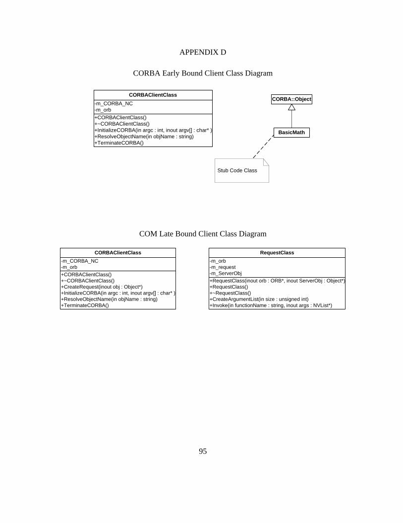
95
APPENDIX D
CORBA Early Bound Client Class Diagram
+CORBAClientClass()+~CORBAClientClass()+InitializeCORBA(in argc : int, inout argv[] : char* )+ResolveObjectName(in objName : string)+TerminateCORBA()
-m_CORBA_NC-m_orb
CORBAClientClass
BasicMath
CORBA::Object
Stub Code Class
COM Late Bound Client Class Diagram
+RequestClass(inout orb : ORB*, inout ServerObj : Object*)+RequestClass()+~RequestClass()+CreateArgumentList(in size : unsigned int)+Invoke(in functionName : string, inout args : NVList*)
-m_orb-m_request-m_ServerObj
RequestClass
+CORBAClientClass()+~CORBAClientClass()+CreateRequest(inout obj : Object*)+InitializeCORBA(in argc : int, inout argv[] : char* )+ResolveObjectName(in objName : string)+TerminateCORBA()
-m_CORBA_NC-m_orb
CORBAClientClass

96
APPENDIX E
Early Bound COM_CORBA Bridge Class Diagram
+HousingManagerClass()+~HousingManagerClass()+CreateObject()+CreatePersistentPOA()+getCOMClient()+InitializeCOM()+InitializeCORBA()+MessageLoop()+ORBShutdown()+RegisterObject()+setPOAManagerActive()+TerminateCOM()+TerminateCORBA()
-m_NamingContext-m_ORB-m_pCOMClient-m_RootPOA-m_RootPOAManager
HousingManagerClass
+CalculatorClass()+~CalculatorClass()+add()
-m_COMProxy-m_pCOMClient
CalculatorClass
-POA_CORBAViewCalculator()#POA_CORBAViewCalculator()+~POA_CORBAViewCalculator()-operator=()+_get_interface()+_is_a()+_make_stub()+_narrow()+_narrow_helper()+_primary_interface()+_this()+dispatch()+invoke()
POA_CORBAViewCalculator
+COMClientClass()+~COMClientClass()+InitializeCOM()+ResolveObjectGUID()+TerminateCOM()
-pClassFactory-pIUnknown
COMClientClass
1
1«instance»
Corba skeleton class:Marshalls parameters betweenCORBA client and bridge
CORBA servant/bridge class:Receives calls from CORBA clientsand makes calls to the COM proxyobject on behalf of CORBA clients.Must have specific type informationabout target object at compile time.
COM proxy class:Makes calls on the target COM object on behalfof the CORBA servant/bridge class

97
APPENDIX F
MIDL Code of the Target COM Object
import "oaidl.idl"; [ object, uuid(51BEE260-CBF9-4f57-86CA-217A7EA2DC71), oleautomation ] interface ICalculator_BasicMath:IUnknown { HRESULT add( [in] short x, [in] short y, [out] long* z ); }; [ uuid(B11E5D95-F527-4de8-8F60-065513920635), //LIBID version(1.0), helpstring("COM Calculator Library") ] library COMCalculatorLibrary { importlib("stdole32.tlb"); [uuid(9FD7A036-D00B-4907-A460-D1212ED68E69)] //CLSID coclass COMCalculator { [default] interface ICalculator_BasicMath; }; };
MIDL to IDL Translation for the CORBA View of the Target Object
interface BasicMath { void add( in short x, in short y, out long z ); }; interface CORBAViewCalculator : BasicMath { };

98
APPENDIX G
Early Bound CORBA_COM Bridge Class Diagram
HousingManagerClass
COMFactoryClass
-theHousingmanager 1
-COMFactory
1..*
ExeHousingManagerClass
RegistrarClass
1
1
«utility»RegistryValueClass
+CreateInstance()
CalculatorFactoryClass
IClassFactory
IUnknown
«instance»
ICalculator_BasicMath
1
1
1
+
«call»
+CalculatorClass()+~CalculatorClass()+AddRef()+getCORBAProxy()+QueryInterface()+Release()
-m_CORBAProxy-m_pCORBAClient-m_pICalculator_BasicMathClass-m_refCount
CalculatorClass
+CORBAClientClass()+~CORBAClientClass()+InitializeCORBA()+ResolveObjectName()+TerminateCORBA()
-m_CORBA_NC-m_orb
CORBAClientClass
«implementation class»ICalculator_BasicMathClass
COM stub class:Marshalls parameters betweenCOM client and bridge.
CORBA proxy class:Makes calls on the target objecton behalf of the COM bridge class.
COM bridge class:Receives calls from COM clientsabd makes calls to the CORBAproxy object on behalfof COMclients. Must have specific typeinformation about the target objectat compile time.

99
APPENDIX H
IDL Code of the Target CORBA Object
interface BasicMath { void Add( in short x, in short y, out long z ); }; interface CORBACalculator : BasicMath { };
IDL to MIDL Translation for the COM View of the Target Object
import "oaidl.idl"; [ object, uuid(0A597D75-FCCD-4f93-A4F0-FAC890A2CEE5), oleautomation ] interface ICalculator_BasicMath:IUnknown { HRESULT Add([in] short x, [in] short y, [out] long* z); }; [ uuid(C2648F1C-3DD1-4da9-A076-42F7E269035C), //LIBID version(1.0), helpstring("COMView Calculator Library") ] library COMViewCalculatorLibrary { importlib("stdole32.tlb"); [uuid(0528DA48-23B1-4da7-8DBC-AD5BC6081C7E)] //CLSID coclass COMViewCalculator { [default] interface ICalculator_BasicMath; }; };

100
APPENDIX I
Late Bound COM_CORBA Bridge Class Diagram
+HousingManagerClass()+~HousingManagerClass()+CreateObject()+CreatePersistentPOA()+getORB()+InitializeCORBA()+MessageLoop()+ORBShutdown()+RegisterObject()+setPOAManagerActive()+TerminateCORBA()
-m_NamingContext-m_ORB-m_RootPOA-m_RootPOAManager
HousingManagerClass
+CORBAViewCreatorClass()+~CORBAViewCreatorClass()+CreateObject()+getORB()
-m_CORBAView-m_ORB-m_pCOMClient
CORBAViewCreatorClass
+_non_existent()+_primary_interface()-getInterfaceDef()-initializeIR()+InitializeProxy()+invoke()-MarshallArguments()-setObjectName()-setORB()-UnMarshallArguments()
-m_intf_def-m_IR-m_ObjectName-m_ORB-m_pCOMClient-m_pIDispatch-m_Request
CORBAView_ProxyClass
+RequestClass()+~RequestClass()+Create_COM_Arguments()+Create_CORBA_Arguments()+Invoke()
-m_arguments-m_intf_def-m_IR-m_orb-m_pIDispatch
RequestClass
-POA_COMFactory()#POA_COMFactory()+~POA_COMFactory()-operator=()+_get_interface()+_is_a()+_make_stub()+_narrow()+_narrow_helper()+_primary_interface()+_this()+CreateObject()+dispatch()+invoke()
POA_COMFactory
«instance»
«instance»
PortableServer::DynamicImplementation
1
*
+COMClientClass()+~COMClientClass()+InitializeCOM()+ResolveObject()+ResolveObjectGUID()+TerminateCOM()
-pClassFactory-pIDispatch
COMClientClass
1
1
CORBA dynamic skeleton class:The CORBA view must inherit fromthis abstract class and implementdynamic skeleton interface (DSI)operations.
CORBA servant/bridge class:Receives calls from CORBA clientsand makes calls to the COM proxyobject on behalf of CORBA clients.Uses type information from aninterface repository to marshallfunction arguments.
COM proxy class:Makes calls on the target COM object on behalfof the CORBA servant/bridge class via theIDispatch interface.

101
APPENDIX J
Late Bound CORBA_COM Bridge Class Diagram
HousingManagerClass
ExeHousingManagerClass
COMFactoryClass
+COMView_ProxyClass()+~COMView_ProxyClass()+AddRef()+CreateRequest()+GetIDsOfNames()-getListofOperations()+GetTypeInfo()+GetTypeInfoCount()+Invoke()-MarshallArguments()+QueryInterface()+Release()-UnMarshallArguments()
COMView_ProxyClass
+CORBA_COM_BridgeClass()+~CORBA_COM_BridgeClass()+AddRef()+CreateObject()+GetIDsOfNames()+GetObjectW()+GetTypeInfo()+GetTypeInfoCount()+GetTypeInfoForGUID()+Invoke()+LoadTypeLibrary()+QueryInterface()+Release()
CORBA_COM_BridgeClass
+CORBA_COM_Bridge_FactoryClass()+~CORBA_COM_Bridge_FactoryClass()+CreateInstance()+getCLSID()+getDescription()+getPROGID()+getVersionIndependentPROGID()
CORBA_COM_Bridge_FactoryClass
+CORBAClientClass()+~CORBAClientClass()+getIR()+getORB()+InitializeCORBA()+ResolveObjectName()+TerminateCORBA()
CORBAClientClass
Windows::IClassFactory
Windows::IUnknown
Windows::IDispatch
1
1
«instance»
1
*
RegistrarClass
1
1
«utility»RegistryValueClass
«instance»
+RequestClass()+~RequestClass()+CreateArgumentList()+Invoke()
RequestClass
1
1
COM View Class:Receives calls from COMclients via IDispatch, andforwards the calls to aCORBA proxy object. Usesinformation from a typeto marshal arguments.
CORBA Proxy Class::Makes calls on the targetCORBA object via DII, onbehalf of CORBA View objects.

102
APPENDIX K
Test Data
COM Client Co-located
test run number
COM object static invocation
COM object dynamic invocation
CORBA object static invocation
CORBA object dynamic invocation
1 110.4 182.0 949.2 4929.1 2 110.7 181.1 949.6 4942.3 3 109.3 183.4 952.9 4941.8 4 109.9 182.4 949.6 4922.8 5 110.1 182.6 953.2 4939.2 6 109.1 189.0 951.8 4938.9 7 109.5 182.3 951.0 4944.4 8 109.3 182.0 957.8 4931.6 9 109.6 182.5 955.3 4927.1
10 109.1 182.1 954.4 4935.1
Median 109.6 182.4 952.4 4937.0
CORBA Client Co-located
test run number
CORBA object static invocation
CORBA object dynamic invocation
COM object static invocation
COM object dynamic invocation
1 457.3 635.7 930.2 5155.1 2 448.5 633.6 942.0 5167.2 3 448.9 630.6 951.5 5177.1 4 449.5 632.8 935.7 5169.7 5 448.1 707.7 941.0 5183.1 6 448.5 635.7 935.9 5189.4 7 449.1 629.1 941.1 5178.6 8 453.0 633.5 934.4 5221.3 9 453.0 633.7 933.3 5192.3
10 450.1 624.8 936.0 5196.1 Median 449.3 633.6 936.0 5180.9

103
COM Client Remote
test run number
COM object static invocation
COM object dynamic invocation
CORBA object static invocation
CORBA object dynamic invocation
1 866.8 1272.9 1578.1 5856.9 2 797.9 1284.0 1571.5 5850.9 3 812.5 1254.2 1576.2 5852.3 4 791.2 1265.8 1565.3 5857.3 5 798.8 1259.0 1587.6 5836.3 6 772.8 1245.6 1562.1 5823.0 7 776.3 1240.5 1571.8 5849.4 8 774.3 1239.1 1577.1 5844.1 9 771.8 1230.7 1559.1 5828.0 10 776.5 1244.4 1563.3 5853.7
Median 783.9 1249.9 1571.7 5850.2
CORBA Client Remote
test run number
CORBA object static invocation
CORBA object dynamic invocation
COM object static invocation
COM object dynamic invocation
1 994.5 1651.1 1468.0 5943.3 2 997.1 1551.0 1302.2 5953.7 3 984.4 1553.8 1297.2 5933.0 4 989.0 1528.5 1299.0 5957.6 5 968.7 1532.9 1287.3 5963.6 6 970.3 1537.2 1282.3 5954.1 7 979.4 1555.4 1282.2 6003.6 8 973.2 1544.1 1286.3 5970.9 9 971.3 1540.7 1281.9 5979.6 10 970.0 1547.1 1273.1 6211.8
Median 976.3 1545.6 1286.8 5960.6

104
REFERENCES AND BIBLIOGRAPHY
[1] Arno Puder, Kay Römer; MICO An Open Source CORBA Implementation; Morgan Kaufmann Publishers 1999
[2] MICO Homepage http://www.mico.org/ (accessed 1/2/03)
[3] TAO Homepage http://www.cs.wustl.edu/~schmidt/TAO.html (accessed 1/2/03)
[4] Michi Henning, Steve Vinoski; Advanced CORBA Programming with C++; Addison Wesley 1999
[5] Kay Römer; MICO is CORBA Eine Erweiterbare CORBA-Implementierung für Forschung und Ausbildung; Diploma Thesis Johann Wolfgang Goethe-University Frankfurt 1998
[6] Fintan Bolton; Pure CORBA; SAMS Publishing 2001
[7] Frank Pillhofer; Design and Implementation of the Portable Object Adapter; Diploma Thesis Johann Wolfgang Goethe-University Frankfurt 1999
[8] OMG, Common Object Request Broker Architecture: Core Specification, December 2002 Version 3.0.2 - Editorial update
[9] OMG, Naming Service Specification, September 2002 Version 1.2, http://www.omg.org
[10] Dale Rogerson, Inside COM, Microsoft Press 1996
[11] Erich Gamma, Richard Helm, Ralph Johnson, John Vlissides; Design Patterns; Addison-Wesley 1994
[12] Kraig Brockschmidt, “Inside OLE” 2nd Ed. Microsoft Press 1995
[13] Birrell, A.D. & Nelson, B.J. "Implementing Remote Procedure Calls." ACM Transactions on Computer Systems 2, 1 (February 1984): 39-59.

105
[14] Andrew S. Tanenbaum, "Computer Networks" Third Edition, Prentice Hall 1994
[15] OMG History, http://www.omg.org/news/about/index.htm (accessed 10/9/03)

106
VITA
EDWIN KRAUS
Personal Data: Date of Birth: January 20, 1970
Place of Birth: Mediasch, Romania
Marital Status: Single
Education: Public High-school, Bochum, Germany
Professional School, Bochum Germany; major in Electronics 1991
FH-Bochum, Bochum, Germany; Bachelor in Mechatronics
(Electrical/Mechanical Engineering & Computer Science),
1997
East Tennessee State University, Johnson City, Tennessee;
Information Science, M.S. 2003
Professional Experience:
Nokia Electronics, Bochum, Germany; Technician, 1987-1991
University of Bochum, Bochum, Germany; Student Assistant,
department of physics, 1995
OVAKO Ajax, York, South Carolina; Engineering Intern 1996
Siemens Energy&Automation, Johnson City, Tennessee; Process
Engineer, since 1997
Honors and Awards: Member of Upsilon Pi Epsilon
Member of Phi Kappa Phi