Interrupts What is an Interrupt?cs5789/2010/slides/Interruptsx2.pdf11/8/10 1 Interrupts Arduino,...
32
11/8/10 1 Interrupts Arduino, AVR, and deep dark programming secrets What is an Interrupt? A transfer of program control that is not directed by the programmer Like a phone call in the middle of a conversation Stop what you are doing, deal with the interruption, then continue where you left off Very handy for handling events that need immediate attention Or that need to occur at regular intervals Or that need to run automatically without the programmer keeping track
Transcript of Interrupts What is an Interrupt?cs5789/2010/slides/Interruptsx2.pdf11/8/10 1 Interrupts Arduino,...
11/8/10
1
Interrupts Arduino, AVR, and deep dark programming secrets
What is an Interrupt?
! A transfer of program control that is not directed by the programmer ! Like a phone call in the middle of a conversation
! Stop what you are doing, deal with the interruption, then continue where you left off
! Very handy for handling events that need immediate attention ! Or that need to occur at regular intervals
! Or that need to run automatically without the programmer keeping track
11/8/10
2
What Happens ! An interrupt is signaled somehow
! A phone rings
! The AVR stops running user code and checks to see what caused the interrupt ! Stop your conversation and check which phone is ringing
! The AVR runs an Interrupt Service Routing (ISR) related to that interrupt ! Answer the phone and handle the call
! The AVR restores the system state and picks up the user code where it left off ! Hang up and resume your previous conversation
Types of Interrupts
! On Arduino/AVR, there are three types ! External: A signal outside the chip (connected to a pin)
! Timer: Internal to the chip, like an alarm clock
! Device: One of the AVR devices (USART, SPI, ADC, EEPROM) signals that it needs attention
11/8/10
3
Example: USART
! USART handles the serial communication between Arduino and the host ! Why not just check for a new character in a loop?
! How frequently would you have to check?
! How much processor time would be spend checking?
Example: USART ! Serial port at 9600 baud (9600 bits/sec)
! Each bit is sent at 9.6 kHz (close to 10kHz)
! Each bit takes around 100usec
! Around 10 bits required for each character
! So, one character every 1msec or so
! If the USART is buffered, you have about 1msec to get a character before it’s overwritten by the next one
! So, you have to check faster than once every millisecond to keep up (around 1000 times a sec) ! If your main loop is not doing anything else, you can do
this, but if you’re doing other things, or communicating at faster speeds, it gets ugly fast
11/8/10
4
Example: USART
! Instead – set up an interrupt handler for the USART ! The USART will cause an interrupt each time it receives
a complete character
! The Interrupt Service Routine (ISR) for this USART-receive event will be called
! The ISR will take the character from the USART and put it in a buffer for your program to use
! You never have to check the USART directly, characters just show up in your program’s buffer as they arrive
Types of Interrupts
! On Arduino/AVR, there are three types ! External: A signal outside the chip (connected to a pin)
! Timer: Internal to the chip, like an alarm clock
! Device: One of the AVR devices (USART, SPI, ADC, EEPROM) signals that it needs attention
11/8/10
5
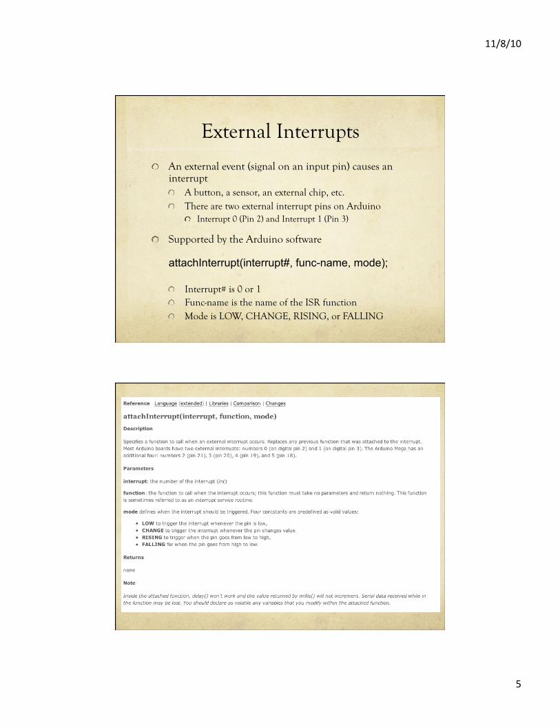
External Interrupts
! An external event (signal on an input pin) causes an interrupt ! A button, a sensor, an external chip, etc. ! There are two external interrupt pins on Arduino
! Interrupt 0 (Pin 2) and Interrupt 1 (Pin 3)
! Supported by the Arduino software
attachInterrupt(interrupt#, func-name, mode);
! Interrupt# is 0 or 1 ! Func-name is the name of the ISR function ! Mode is LOW, CHANGE, RISING, or FALLING
11/8/10
6
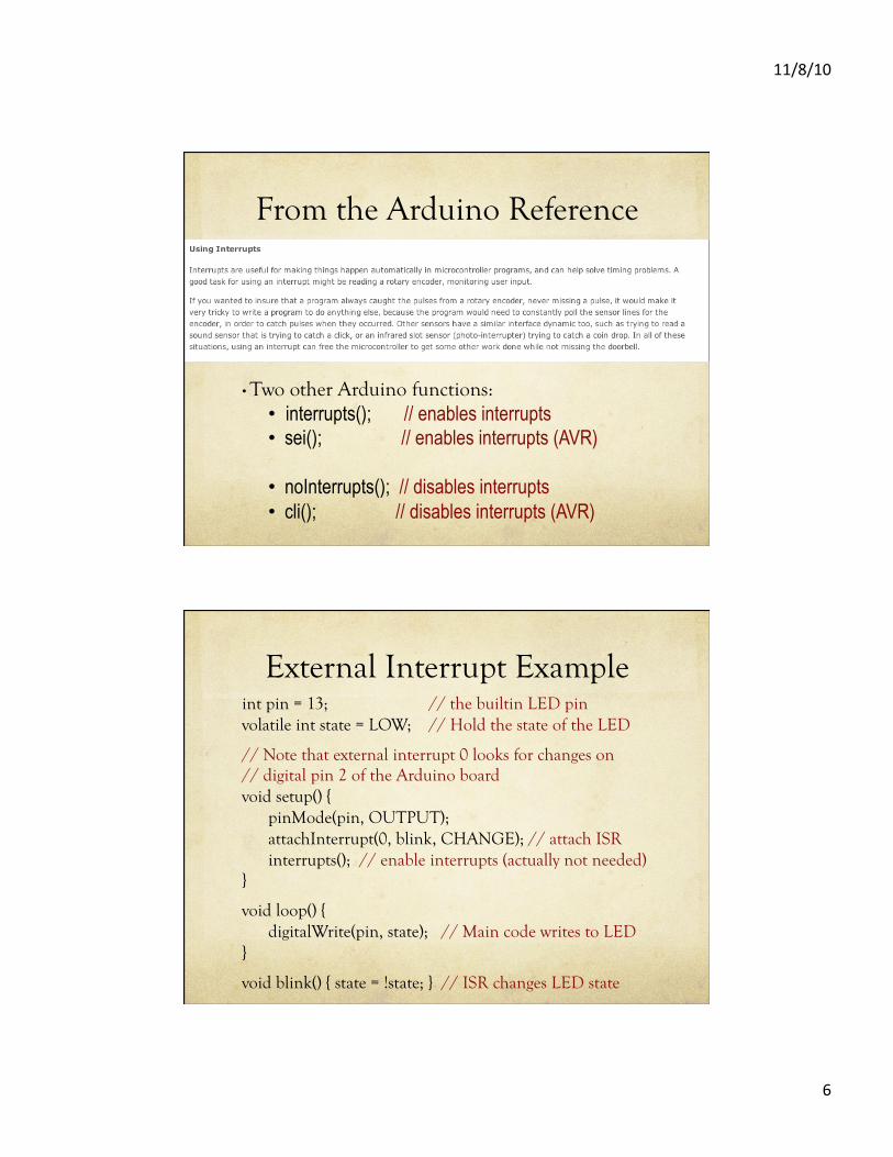
From the Arduino Reference
• Two other Arduino functions: • interrupts(); // enables interrupts • sei(); // enables interrupts (AVR)
• noInterrupts(); // disables interrupts • cli(); // disables interrupts (AVR)
External Interrupt Example int pin = 13; // the builtin LED pin volatile int state = LOW; // Hold the state of the LED
// Note that external interrupt 0 looks for changes on // digital pin 2 of the Arduino board void setup() {
pinMode(pin, OUTPUT); attachInterrupt(0, blink, CHANGE); // attach ISR interrupts(); // enable interrupts (actually not needed)
}
void loop() { digitalWrite(pin, state); // Main code writes to LED
}
void blink() { state = !state; } // ISR changes LED state
11/8/10
7
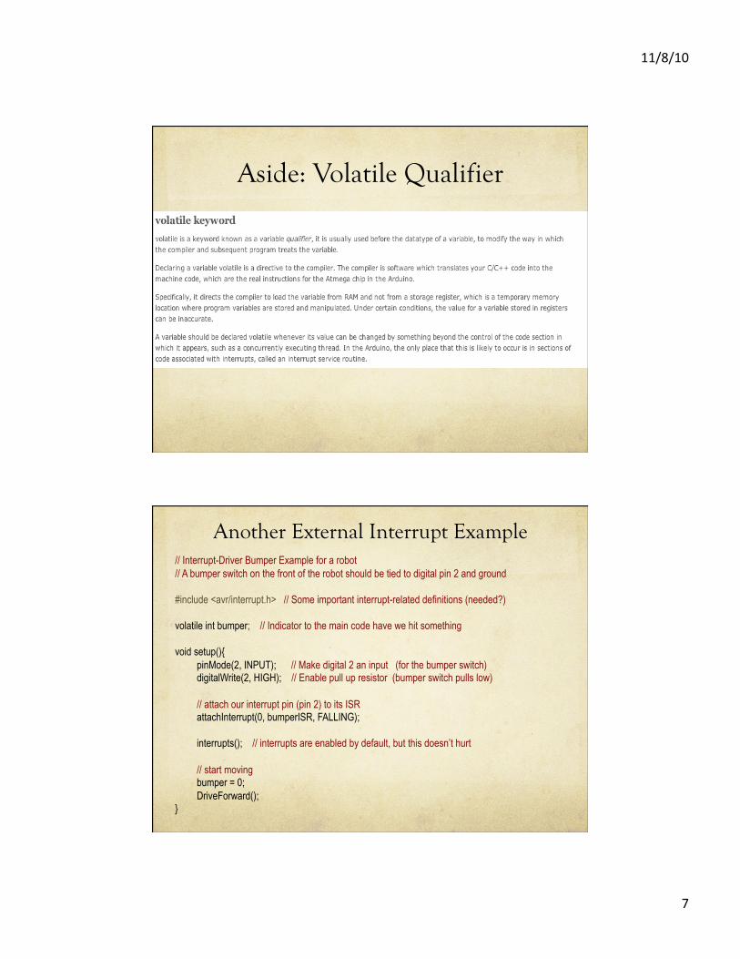
Aside: Volatile Qualifier
Another External Interrupt Example // Interrupt-Driver Bumper Example for a robot // A bumper switch on the front of the robot should be tied to digital pin 2 and ground
#include <avr/interrupt.h> // Some important interrupt-related definitions (needed?)
volatile int bumper; // Indicator to the main code have we hit something
void setup(){ pinMode(2, INPUT); // Make digital 2 an input (for the bumper switch) digitalWrite(2, HIGH); // Enable pull up resistor (bumper switch pulls low)
// attach our interrupt pin (pin 2) to its ISR attachInterrupt(0, bumperISR, FALLING);
interrupts(); // interrupts are enabled by default, but this doesn’t hurt
// start moving bumper = 0; DriveForward();
}
11/8/10
8
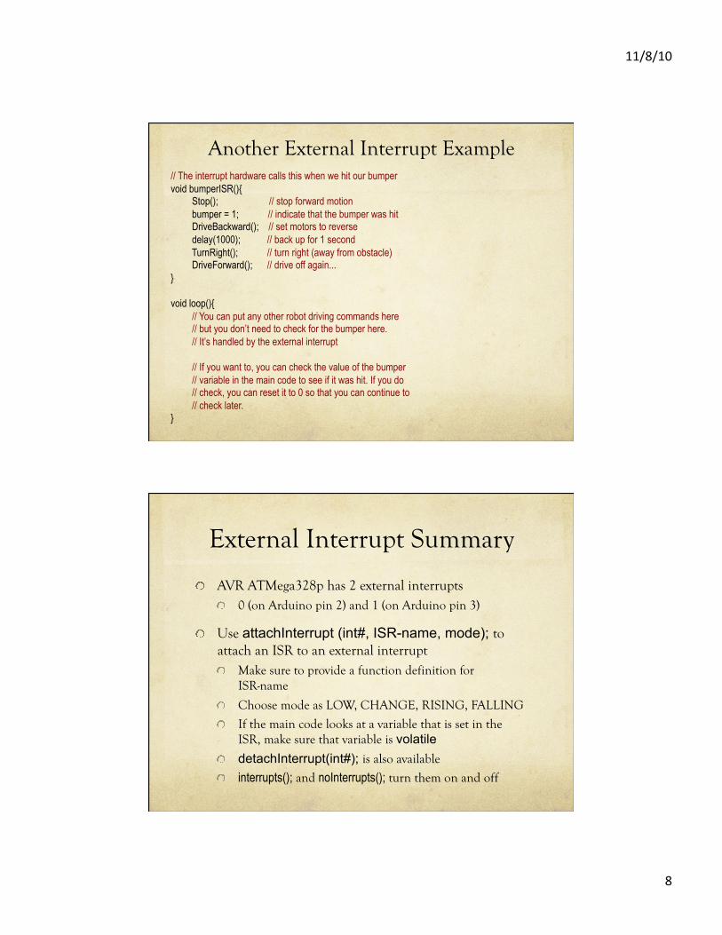
Another External Interrupt Example // The interrupt hardware calls this when we hit our bumper void bumperISR(){
Stop(); // stop forward motion bumper = 1; // indicate that the bumper was hit DriveBackward(); // set motors to reverse delay(1000); // back up for 1 second TurnRight(); // turn right (away from obstacle) DriveForward(); // drive off again...
}
void loop(){ // You can put any other robot driving commands here // but you don’t need to check for the bumper here. // It’s handled by the external interrupt
// If you want to, you can check the value of the bumper // variable in the main code to see if it was hit. If you do // check, you can reset it to 0 so that you can continue to // check later.
}
External Interrupt Summary
! AVR ATMega328p has 2 external interrupts ! 0 (on Arduino pin 2) and 1 (on Arduino pin 3)
! Use attachInterrupt (int#, ISR-name, mode); to attach an ISR to an external interrupt ! Make sure to provide a function definition for
ISR-name
! Choose mode as LOW, CHANGE, RISING, FALLING
! If the main code looks at a variable that is set in the ISR, make sure that variable is volatile
! detachInterrupt(int#); is also available
! interrupts(); and noInterrupts(); turn them on and off
11/8/10
9
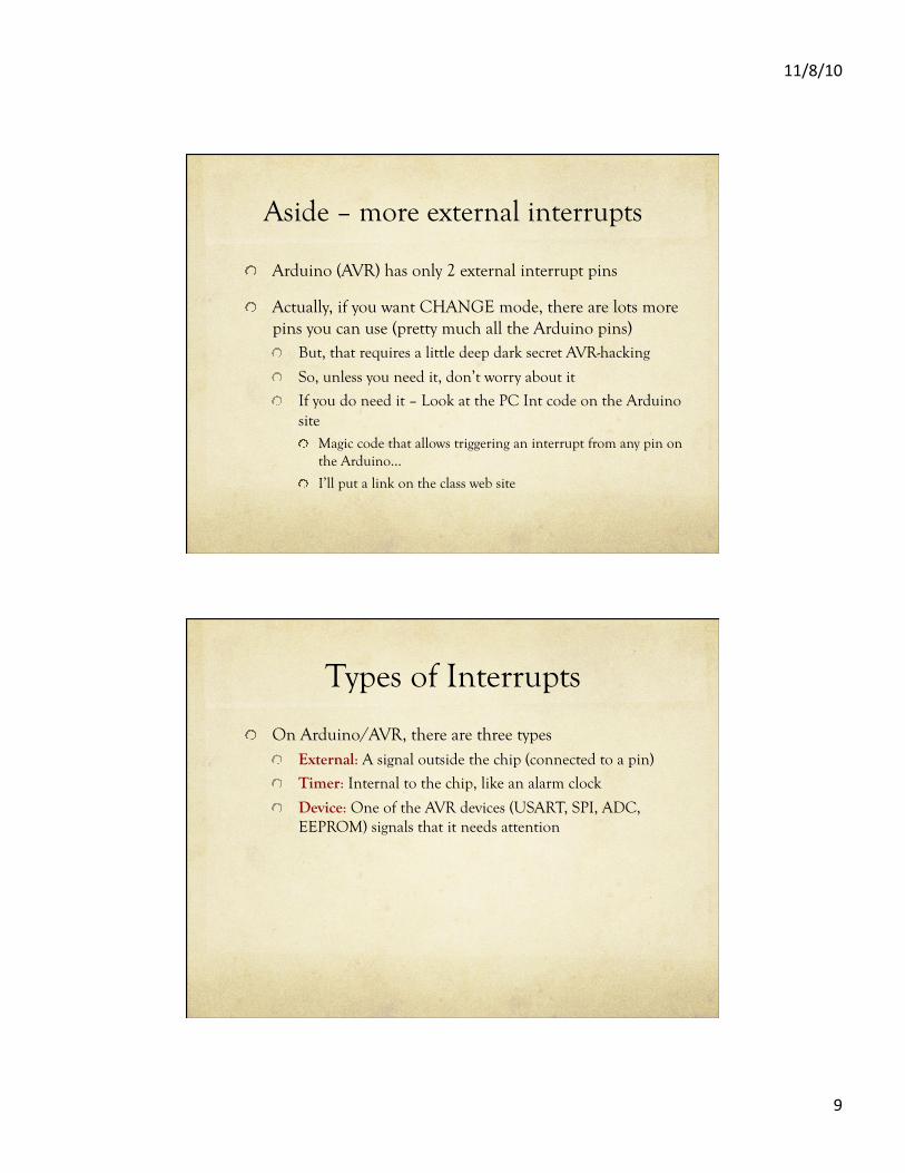
Aside – more external interrupts
! Arduino (AVR) has only 2 external interrupt pins
! Actually, if you want CHANGE mode, there are lots more pins you can use (pretty much all the Arduino pins) ! But, that requires a little deep dark secret AVR-hacking
! So, unless you need it, don’t worry about it
! If you do need it – Look at the PC Int code on the Arduino site ! Magic code that allows triggering an interrupt from any pin on
the Arduino…
! I’ll put a link on the class web site
Types of Interrupts
! On Arduino/AVR, there are three types ! External: A signal outside the chip (connected to a pin)
! Timer: Internal to the chip, like an alarm clock
! Device: One of the AVR devices (USART, SPI, ADC, EEPROM) signals that it needs attention
11/8/10
10
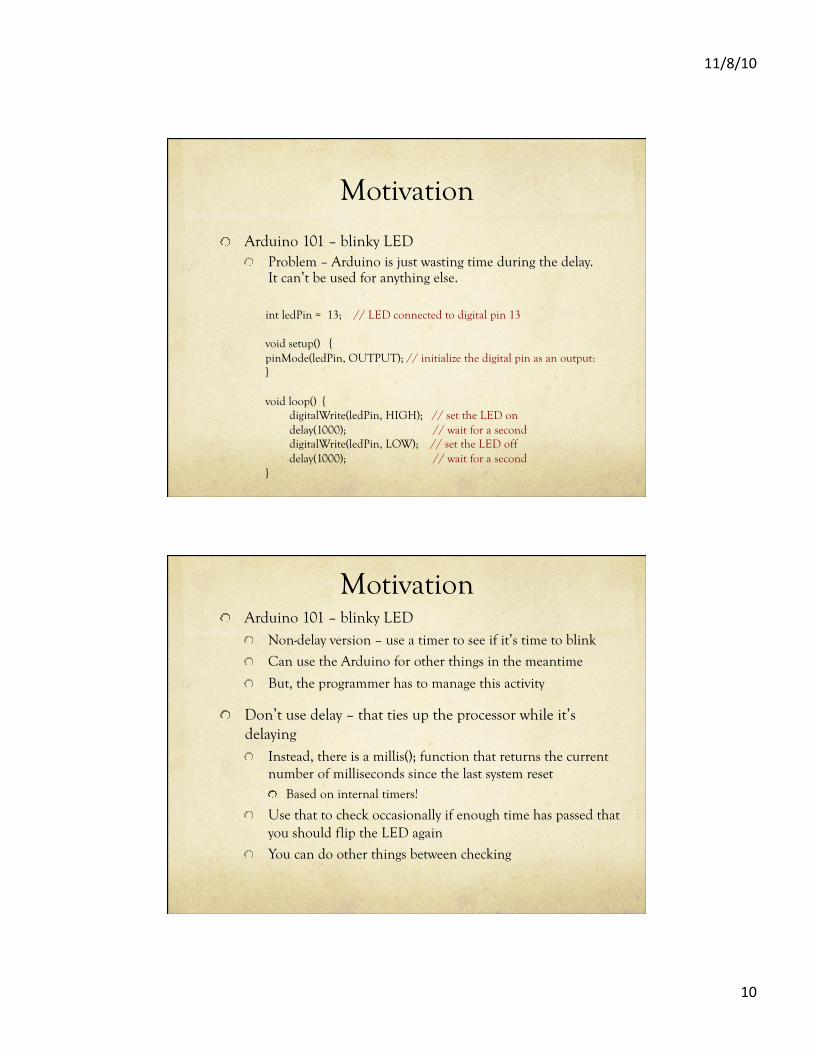
Motivation
! Arduino 101 – blinky LED ! Problem – Arduino is just wasting time during the delay.
It can’t be used for anything else.
int ledPin = 13; // LED connected to digital pin 13
void setup() { pinMode(ledPin, OUTPUT); // initialize the digital pin as an output: }
void loop() { digitalWrite(ledPin, HIGH); // set the LED on delay(1000); // wait for a second digitalWrite(ledPin, LOW); // set the LED off delay(1000); // wait for a second
}
Motivation ! Arduino 101 – blinky LED
! Non-delay version – use a timer to see if it’s time to blink
! Can use the Arduino for other things in the meantime
! But, the programmer has to manage this activity
! Don’t use delay – that ties up the processor while it’s delaying ! Instead, there is a millis(); function that returns the current
number of milliseconds since the last system reset ! Based on internal timers!
! Use that to check occasionally if enough time has passed that you should flip the LED again
! You can do other things between checking
11/8/10
11
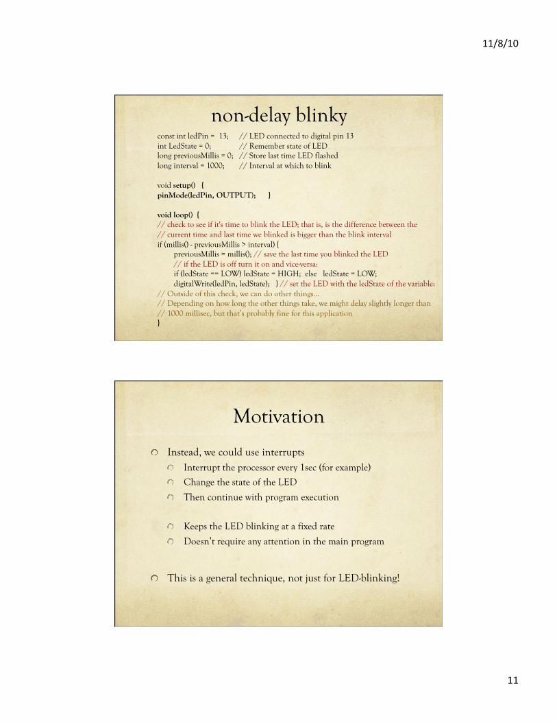
non-delay blinky const int ledPin = 13; // LED connected to digital pin 13 int LedState = 0; // Remember state of LED long previousMillis = 0; // Store last time LED flashed long interval = 1000; // Interval at which to blink
void setup() { pinMode(ledPin, OUTPUT); }
void loop() { // check to see if it's time to blink the LED; that is, is the difference between the // current time and last time we blinked is bigger than the blink interval if (millis() - previousMillis > interval) {
previousMillis = millis(); // save the last time you blinked the LED // if the LED is off turn it on and vice-versa: if (ledState == LOW) ledState = HIGH; else ledState = LOW; digitalWrite(ledPin, ledState); } // set the LED with the ledState of the variable:
// Outside of this check, we can do other things… // Depending on how long the other things take, we might delay slightly longer than // 1000 millisec, but that’s probably fine for this application }
Motivation
! Instead, we could use interrupts ! Interrupt the processor every 1sec (for example)
! Change the state of the LED
! Then continue with program execution
! Keeps the LED blinking at a fixed rate
! Doesn’t require any attention in the main program
! This is a general technique, not just for LED-blinking!
11/8/10
12
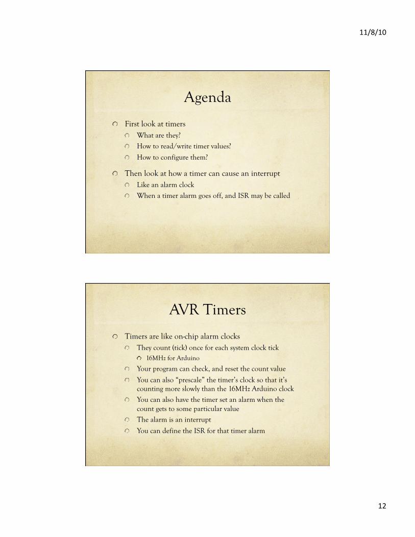
Agenda
! First look at timers ! What are they?
! How to read/write timer values?
! How to configure them?
! Then look at how a timer can cause an interrupt ! Like an alarm clock
! When a timer alarm goes off, and ISR may be called
AVR Timers
! Timers are like on-chip alarm clocks ! They count (tick) once for each system clock tick
! 16MHz for Arduino
! Your program can check, and reset the count value
! You can also “prescale” the timer’s clock so that it’s counting more slowly than the 16MHz Arduino clock
! You can also have the timer set an alarm when the count gets to some particular value
! The alarm is an interrupt
! You can define the ISR for that timer alarm
11/8/10
13
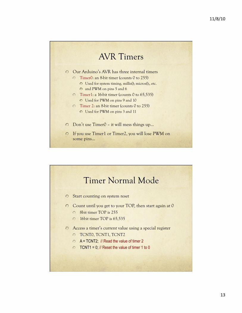
AVR Timers
! Our Arduino’s AVR has three internal timers ! Timer0: an 8-bit timer (counts 0 to 255)
! Used for system timing, millis(); micros();, etc. ! and PWM on pins 5 and 6
! Timer1: a 16-bit timer (counts 0 to 65,535) ! Used for PWM on pins 9 and 10
! Timer 2: an 8-bit timer (counts 0 to 255) ! Used for PWM on pins 3 and 11
! Don’t use Timer0 – it will mess things up…
! If you use Timer1 or Timer2, you will lose PWM on some pins…
Timer Normal Mode
! Start counting on system reset
! Count until you get to your TOP, then start again at 0 ! 8bit timer TOP is 255
! 16bit timer TOP is 65,535
! Access a timer’s current value using a special register ! TCNT0, TCNT1, TCNT2
! A = TCNT2; // Read the value of timer 2 ! TCNT1 = 0; // Reset the value of timer 1 to 0
11/8/10
14
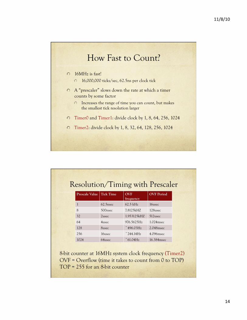
How Fast to Count?
! 16MHz is fast! ! 16,000,000 ticks/sec, 62.5ns per clock tick
! A “prescaler” slows down the rate at which a timer counts by some factor ! Increases the range of time you can count, but makes
the smallest tick resolution larger
! Timer0 and Timer1: divide clock by 1, 8, 64, 256, 1024
! Timer2: divide clock by 1, 8, 32, 64, 128, 256, 1024
Resolution/Timing with Prescaler Prescale Value Tick Time OVF
frequency OVF Period
1 62.5nsec 62.5 kHz 16usec
8 500nsec 7.8125kHZ 128usec
32 2usec 1.953125kHZ 512usec
64 4usec 976.5625Hz 1.024msec
128 8usec ~496.03Hz 2.048msec
256 16usec ~244.14Hz 4.096msec
1024 64usec ~61.04Hz 16.384msec
8-bit counter at 16MHz system clock frequency (Timer2) OVF = Overflow (time it takes to count from 0 to TOP) TOP = 255 for an 8-bit counter
11/8/10
15
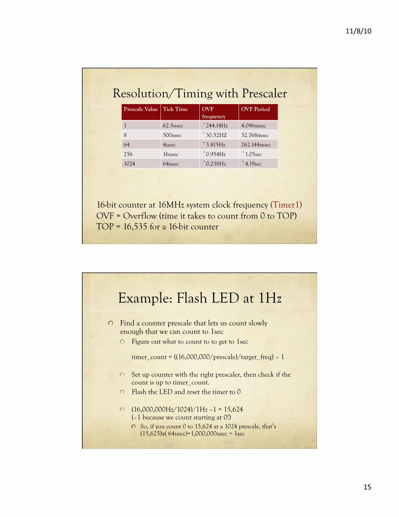
Resolution/Timing with Prescaler Prescale Value Tick Time OVF
frequency OVF Period
1 62.5nsec ~244.14Hz 4.096msec
8 500nsec ~30.52HZ 32.768msec
64 4usec ~3.815Hz 262.144msec
256 16usec ~0.954Hz ~1.05sec
1024 64usec ~0.238Hz ~4.19sec
16-bit counter at 16MHz system clock frequency (Timer1) OVF = Overflow (time it takes to count from 0 to TOP) TOP = 16,535 for a 16-bit counter
Example: Flash LED at 1Hz
! Find a counter prescale that lets us count slowly enough that we can count to 1sec ! Figure out what to count to to get to 1sec
timer_count = ((16,000,000/prescale)/target_freq) – 1
! Set up counter with the right prescaler, then check if the count is up to timer_count.
! Flash the LED and reset the timer to 0
! (16,000,000Hz/1024)/1Hz –1 = 15,624 (–1 because we count starting at 0!) ! So, if you count 0 to 15,624 at a 1024 prescale, that’s
(15,625)x( 64usec)=1,000,000usec = 1sec
11/8/10
16
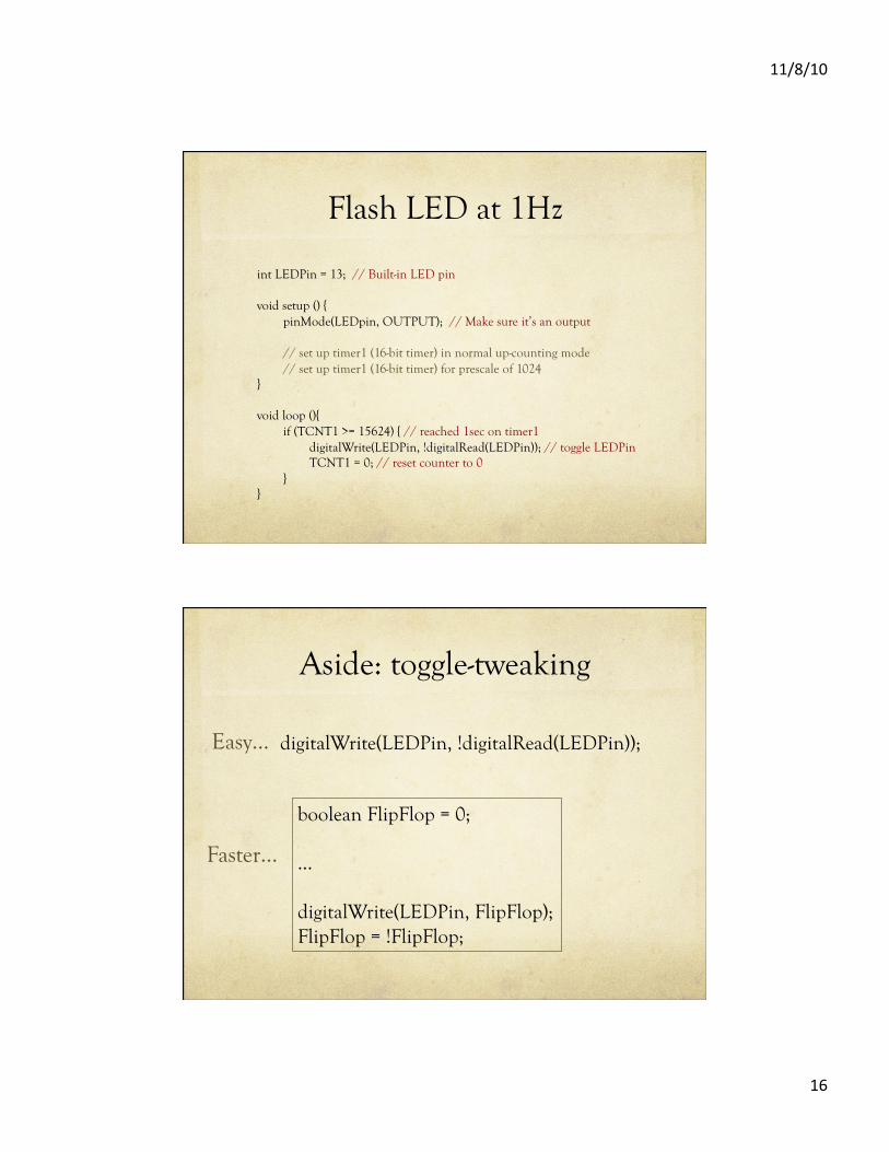
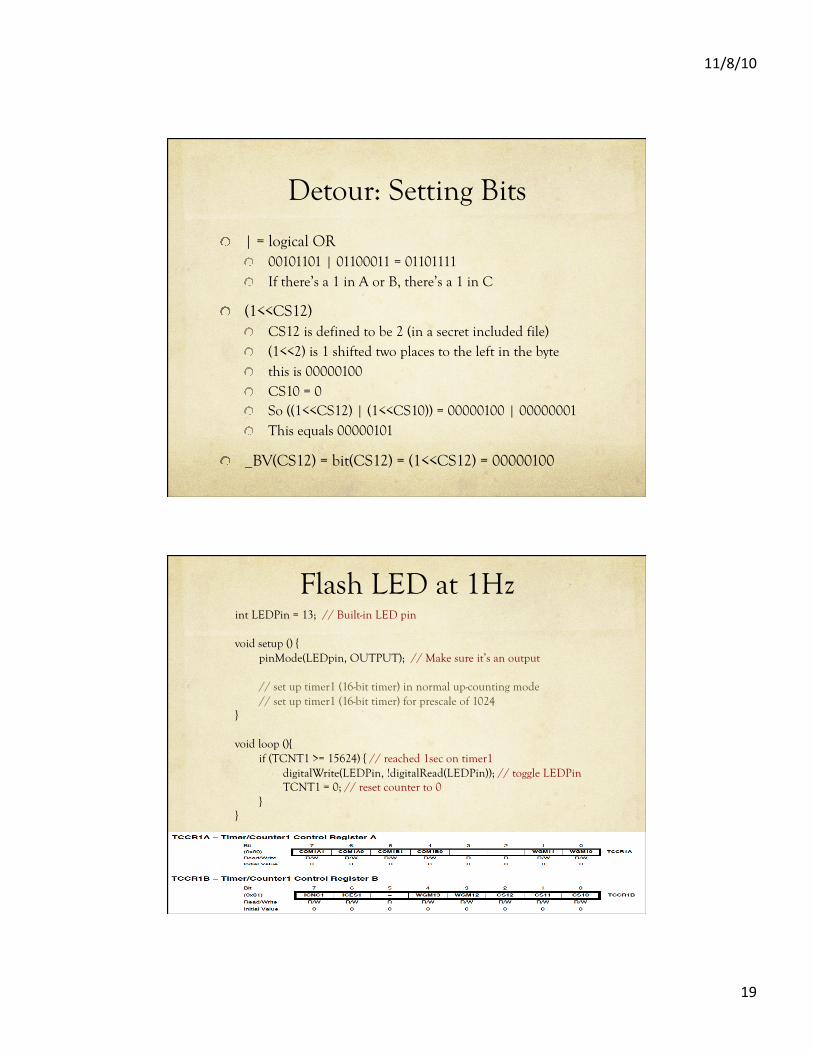
Flash LED at 1Hz
int LEDPin = 13; // Built-in LED pin
void setup () { pinMode(LEDpin, OUTPUT); // Make sure it’s an output
// set up timer1 (16-bit timer) in normal up-counting mode // set up timer1 (16-bit timer) for prescale of 1024
}
void loop (){ if (TCNT1 >= 15624) { // reached 1sec on timer1 digitalWrite(LEDPin, !digitalRead(LEDPin)); // toggle LEDPin TCNT1 = 0; // reset counter to 0 }
}
Aside: toggle-tweaking
digitalWrite(LEDPin, !digitalRead(LEDPin));
boolean FlipFlop = 0;
…
digitalWrite(LEDPin, FlipFlop); FlipFlop = !FlipFlop;
Easy…
Faster…
11/8/10
17
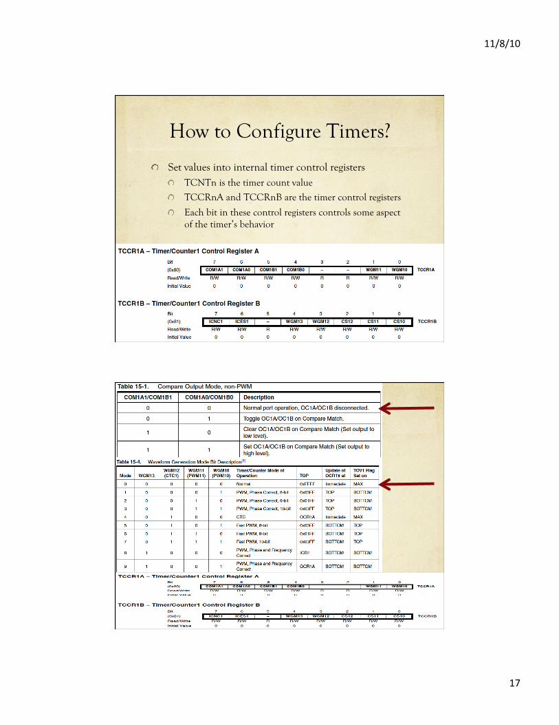
How to Configure Timers?
! Set values into internal timer control registers ! TCNTn is the timer count value
! TCCRnA and TCCRnB are the timer control registers
! Each bit in these control registers controls some aspect of the timer’s behavior
11/8/10
18
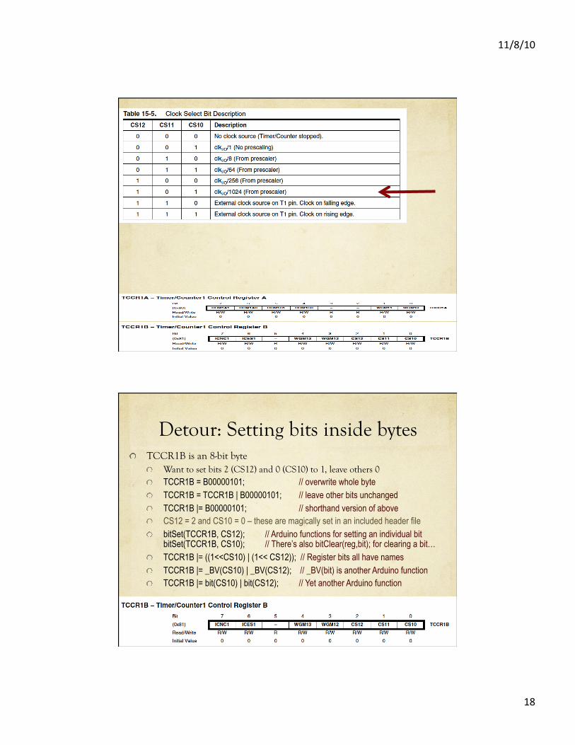
Detour: Setting bits inside bytes ! TCCR1B is an 8-bit byte
! Want to set bits 2 (CS12) and 0 (CS10) to 1, leave others 0 ! TCCR1B = B00000101; // overwrite whole byte ! TCCR1B = TCCR1B | B00000101; // leave other bits unchanged ! TCCR1B |= B00000101; // shorthand version of above ! CS12 = 2 and CS10 = 0 – these are magically set in an included header file ! bitSet(TCCR1B, CS12); // Arduino functions for setting an individual bit
bitSet(TCCR1B, CS10); // There’s also bitClear(reg,bit); for clearing a bit… ! TCCR1B |= ((1<<CS10) | (1<< CS12)); // Register bits all have names ! TCCR1B |= _BV(CS10) | _BV(CS12); // _BV(bit) is another Arduino function ! TCCR1B |= bit(CS10) | bit(CS12); // Yet another Arduino function
11/8/10
19
Detour: Setting Bits
! | = logical OR ! 00101101 | 01100011 = 01101111 ! If there’s a 1 in A or B, there’s a 1 in C
! (1<<CS12) ! CS12 is defined to be 2 (in a secret included file) ! (1<<2) is 1 shifted two places to the left in the byte ! this is 00000100 ! CS10 = 0 ! So ((1<<CS12) | (1<<CS10)) = 00000100 | 00000001 ! This equals 00000101
! _BV(CS12) = bit(CS12) = (1<<CS12) = 00000100
Flash LED at 1Hz int LEDPin = 13; // Built-in LED pin
void setup () { pinMode(LEDpin, OUTPUT); // Make sure it’s an output
// set up timer1 (16-bit timer) in normal up-counting mode // set up timer1 (16-bit timer) for prescale of 1024
}
void loop (){ if (TCNT1 >= 15624) { // reached 1sec on timer1 digitalWrite(LEDPin, !digitalRead(LEDPin)); // toggle LEDPin TCNT1 = 0; // reset counter to 0 }
}
11/8/10
20
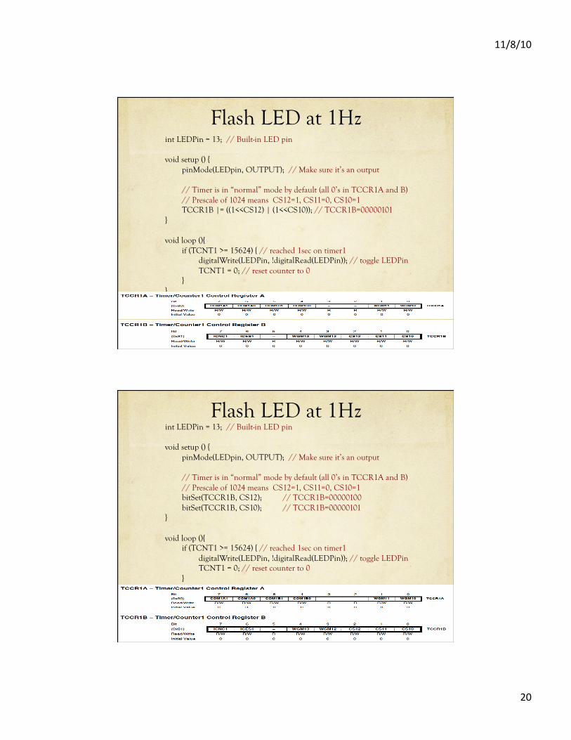
Flash LED at 1Hz int LEDPin = 13; // Built-in LED pin
void setup () { pinMode(LEDpin, OUTPUT); // Make sure it’s an output
// Timer is in “normal” mode by default (all 0’s in TCCR1A and B) // Prescale of 1024 means CS12=1, CS11=0, CS10=1 TCCR1B |= ((1<<CS12) | (1<<CS10)); // TCCR1B=00000101
}
void loop (){ if (TCNT1 >= 15624) { // reached 1sec on timer1 digitalWrite(LEDPin, !digitalRead(LEDPin)); // toggle LEDPin TCNT1 = 0; // reset counter to 0 }
}
Flash LED at 1Hz int LEDPin = 13; // Built-in LED pin
void setup () { pinMode(LEDpin, OUTPUT); // Make sure it’s an output
// Timer is in “normal” mode by default (all 0’s in TCCR1A and B) // Prescale of 1024 means CS12=1, CS11=0, CS10=1 bitSet(TCCR1B, CS12); // TCCR1B=00000100
bitSet(TCCR1B, CS10); // TCCR1B=00000101 }
void loop (){ if (TCNT1 >= 15624) { // reached 1sec on timer1 digitalWrite(LEDPin, !digitalRead(LEDPin)); // toggle LEDPin TCNT1 = 0; // reset counter to 0 }
}
11/8/10
21
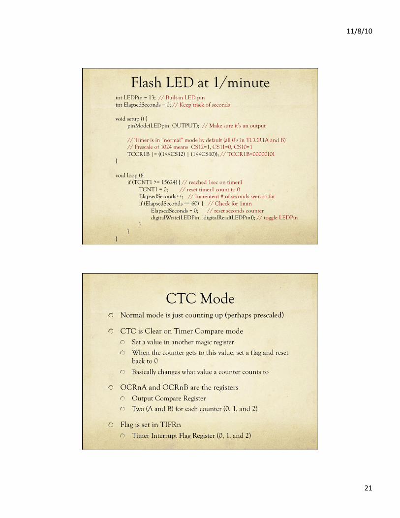
Flash LED at 1/minute int LEDPin = 13; // Built-in LED pin int ElapsedSeconds = 0; // Keep track of seconds
void setup () { pinMode(LEDpin, OUTPUT); // Make sure it’s an output
// Timer is in “normal” mode by default (all 0’s in TCCR1A and B) // Prescale of 1024 means CS12=1, CS11=0, CS10=1 TCCR1B |= ((1<<CS12) | (1<<CS10)); // TCCR1B=00000101
}
void loop (){ if (TCNT1 >= 15624) { // reached 1sec on timer1 TCNT1 = 0; // reset timer1 count to 0 ElapsedSeconds++; // Increment # of seconds seen so far if (ElapsedSeconds == 60) { // Check for 1min ElapsedSeconds = 0; // reset seconds counter digitalWrite(LEDPin, !digitalRead(LEDPin)); // toggle LEDPin } }
}
CTC Mode ! Normal mode is just counting up (perhaps prescaled)
! CTC is Clear on Timer Compare mode ! Set a value in another magic register
! When the counter gets to this value, set a flag and reset back to 0
! Basically changes what value a counter counts to
! OCRnA and OCRnB are the registers ! Output Compare Register
! Two (A and B) for each counter (0, 1, and 2)
! Flag is set in TIFRn ! Timer Interrupt Flag Register (0, 1, and 2)
11/8/10
22
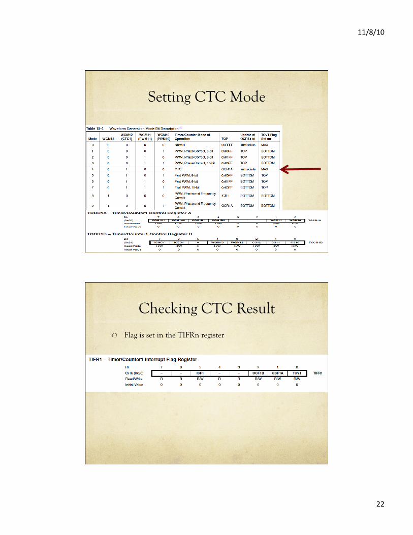
Setting CTC Mode
Checking CTC Result
! Flag is set in the TIFRn register
11/8/10
23
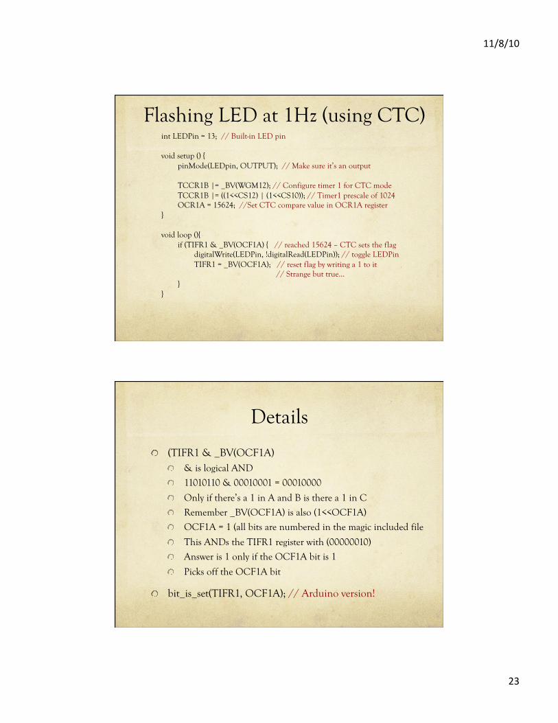
Flashing LED at 1Hz (using CTC) int LEDPin = 13; // Built-in LED pin
void setup () { pinMode(LEDpin, OUTPUT); // Make sure it’s an output
TCCR1B |= _BV(WGM12); // Configure timer 1 for CTC mode TCCR1B |= ((1<<CS12) | (1<<CS10)); // Timer1 prescale of 1024 OCR1A = 15624; //Set CTC compare value in OCR1A register
}
void loop (){ if (TIFR1 & _BV(OCF1A) { // reached 15624 – CTC sets the flag digitalWrite(LEDPin, !digitalRead(LEDPin)); // toggle LEDPin TIFR1 = _BV(OCF1A); // reset flag by writing a 1 to it // Strange but true… }
}
Details
! (TIFR1 & _BV(OCF1A) ! & is logical AND
! 11010110 & 00010001 = 00010000
! Only if there’s a 1 in A and B is there a 1 in C
! Remember _BV(OCF1A) is also (1<<OCF1A)
! OCF1A = 1 (all bits are numbered in the magic included file
! This ANDs the TIFR1 register with (00000010)
! Answer is 1 only if the OCF1A bit is 1
! Picks off the OCF1A bit
! bit_is_set(TIFR1, OCF1A); // Arduino version!
11/8/10
24
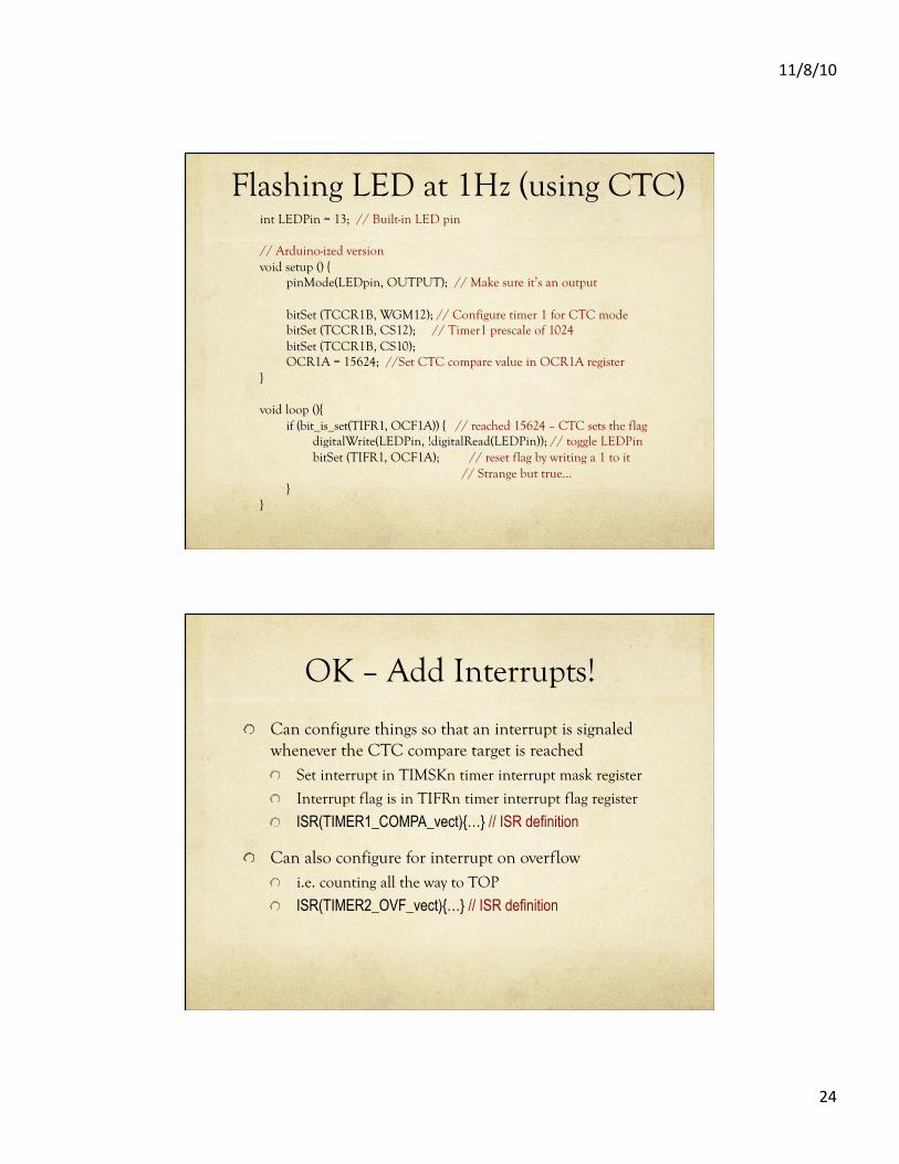
Flashing LED at 1Hz (using CTC) int LEDPin = 13; // Built-in LED pin
// Arduino-ized version void setup () {
pinMode(LEDpin, OUTPUT); // Make sure it’s an output
bitSet (TCCR1B, WGM12); // Configure timer 1 for CTC mode bitSet (TCCR1B, CS12); // Timer1 prescale of 1024 bitSet (TCCR1B, CS10); OCR1A = 15624; //Set CTC compare value in OCR1A register
}
void loop (){ if (bit_is_set(TIFR1, OCF1A)) { // reached 15624 – CTC sets the flag digitalWrite(LEDPin, !digitalRead(LEDPin)); // toggle LEDPin bitSet (TIFR1, OCF1A); // reset flag by writing a 1 to it // Strange but true… }
}
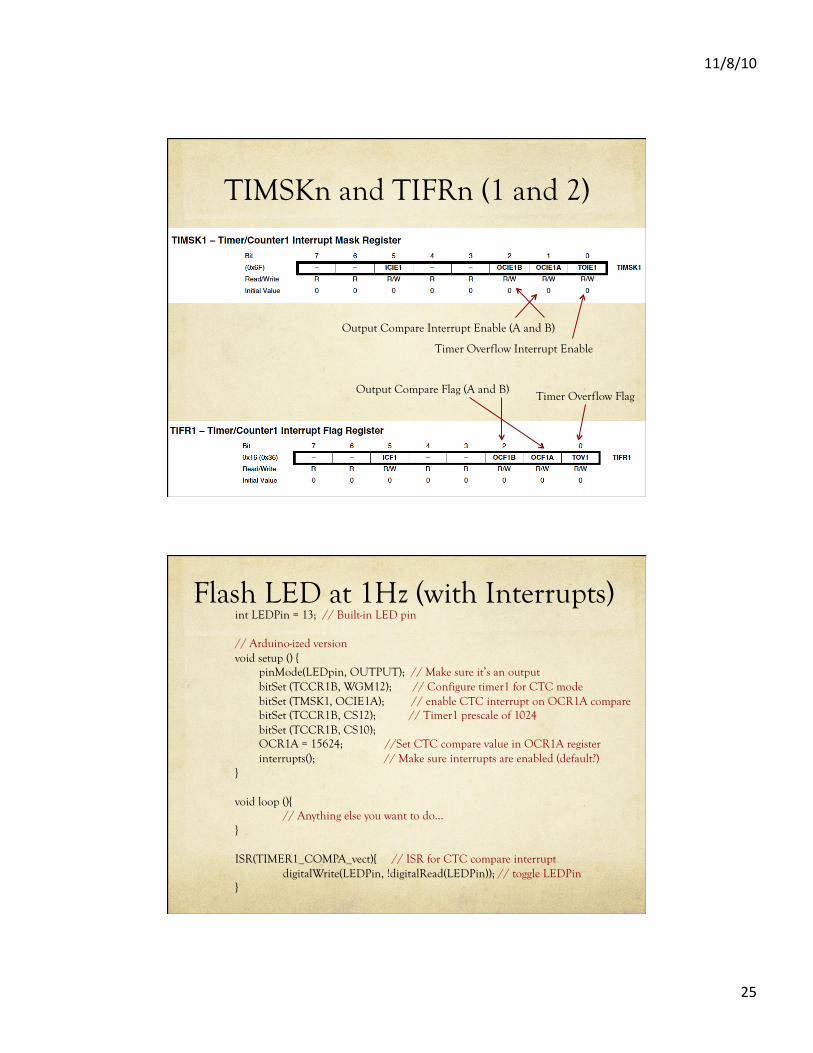
OK – Add Interrupts!
! Can configure things so that an interrupt is signaled whenever the CTC compare target is reached ! Set interrupt in TIMSKn timer interrupt mask register
! Interrupt flag is in TIFRn timer interrupt flag register
! ISR(TIMER1_COMPA_vect){…} // ISR definition
! Can also configure for interrupt on overflow ! i.e. counting all the way to TOP
! ISR(TIMER2_OVF_vect){…} // ISR definition
11/8/10
25
TIMSKn and TIFRn (1 and 2)
Output Compare Interrupt Enable (A and B)
Timer Overflow Interrupt Enable
Output Compare Flag (A and B) Timer Overflow Flag
Flash LED at 1Hz (with Interrupts) int LEDPin = 13; // Built-in LED pin
// Arduino-ized version void setup () {
pinMode(LEDpin, OUTPUT); // Make sure it’s an output bitSet (TCCR1B, WGM12); // Configure timer1 for CTC mode bitSet (TMSK1, OCIE1A); // enable CTC interrupt on OCR1A compare bitSet (TCCR1B, CS12); // Timer1 prescale of 1024 bitSet (TCCR1B, CS10); OCR1A = 15624; //Set CTC compare value in OCR1A register
interrupts(); // Make sure interrupts are enabled (default?) }
void loop (){ // Anything else you want to do…
}
ISR(TIMER1_COMPA_vect){ // ISR for CTC compare interrupt digitalWrite(LEDPin, !digitalRead(LEDPin)); // toggle LEDPin
}
11/8/10
26
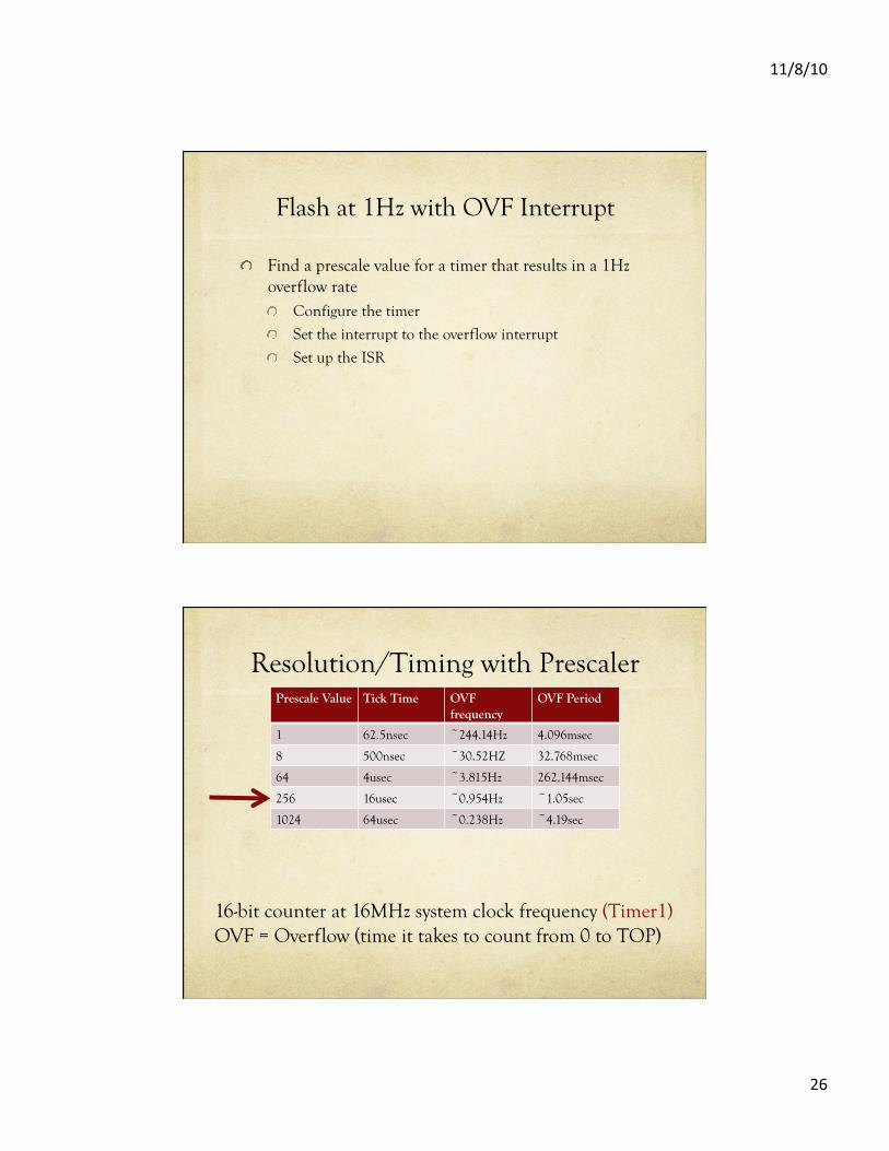
Flash at 1Hz with OVF Interrupt
! Find a prescale value for a timer that results in a 1Hz overflow rate ! Configure the timer
! Set the interrupt to the overflow interrupt
! Set up the ISR
Resolution/Timing with Prescaler Prescale Value Tick Time OVF
frequency OVF Period
1 62.5nsec ~244.14Hz 4.096msec
8 500nsec ~30.52HZ 32.768msec
64 4usec ~3.815Hz 262.144msec
256 16usec ~0.954Hz ~1.05sec
1024 64usec ~0.238Hz ~4.19sec
16-bit counter at 16MHz system clock frequency (Timer1) OVF = Overflow (time it takes to count from 0 to TOP)
11/8/10
27
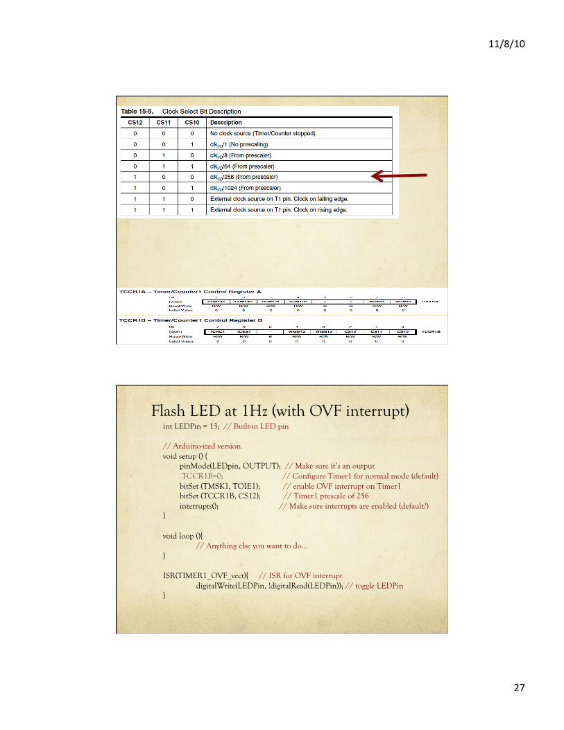
Flash LED at 1Hz (with OVF interrupt) int LEDPin = 13; // Built-in LED pin
// Arduino-ized version void setup () {
pinMode(LEDpin, OUTPUT); // Make sure it’s an output TCCR1B=0; // Configure Timer1 for normal mode (default) bitSet (TMSK1, TOIE1); // enable OVF interrupt on Timer1 bitSet (TCCR1B, CS12); // Timer1 prescale of 256
interrupts(); // Make sure interrupts are enabled (default?) }
void loop (){ // Anything else you want to do…
}
ISR(TIMER1_OVF_vect){ // ISR for OVF interrupt digitalWrite(LEDPin, !digitalRead(LEDPin)); // toggle LEDPin
}
11/8/10
28
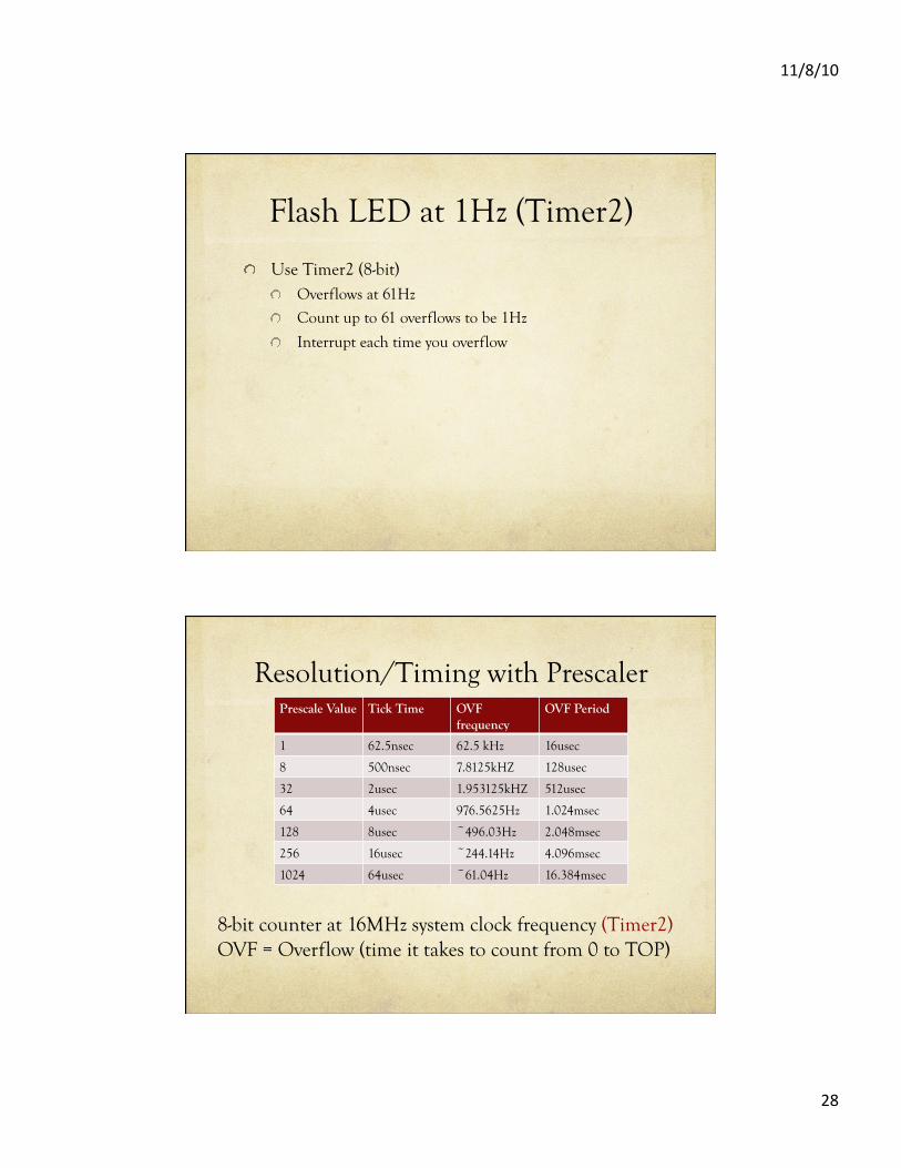
Flash LED at 1Hz (Timer2)
! Use Timer2 (8-bit) ! Overflows at 61Hz
! Count up to 61 overflows to be 1Hz
! Interrupt each time you overflow
Resolution/Timing with Prescaler Prescale Value Tick Time OVF
frequency OVF Period
1 62.5nsec 62.5 kHz 16usec
8 500nsec 7.8125kHZ 128usec
32 2usec 1.953125kHZ 512usec
64 4usec 976.5625Hz 1.024msec
128 8usec ~496.03Hz 2.048msec
256 16usec ~244.14Hz 4.096msec
1024 64usec ~61.04Hz 16.384msec
8-bit counter at 16MHz system clock frequency (Timer2) OVF = Overflow (time it takes to count from 0 to TOP)
11/8/10
29
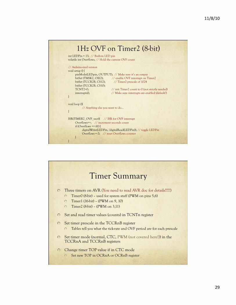
1Hz OVF on Timer2 (8-bit) int LEDPin = 13; // Built-in LED pin volatile int Overflows; // Hold the current OVF count
// Arduino-ized version void setup () {
pinMode(LEDpin, OUTPUT); // Make sure it’s an output bitSet (TMSK2, OIE2); // enable OVF interrupt on Timer2 bitSet (TCCR2B, CS12); // Timer2 prescale of 1024 bitSet (TCCR2B, CS10); TCNT2=0; // init Timer2 count to 0 (not strictly needed)
interrupts(); // Make sure interrupts are enabled (default?) }
void loop (){ // Anything else you want to do…
}
ISR(TIMER2_OVF_vect){ // ISR for OVF interrupt Overflows++; // increment seconds count if (Overflows == 61) { digitalWrite(LEDPin, !digitalRead(LEDPin)); // toggle LEDPin Overflows = 0; // reset Overflows counter }
}
Timer Summary
! Three timers on AVR (You need to read AVR doc for details!!!!!) ! Timer0 (8-bit) – used for system stuff (PWM on pins 5,6) ! Timer1 (16-bit) – (PWM on 9, 10) ! Timer2 (8-bit) – (PWM on 3,11)
! Set and read timer values (counts) in TCNTn register
! Set timer prescale in the TCCRnB register ! Tables tell you what the tick-rate and OVF period are for each prescale
! Set timer mode (normal, CTC, PWM (not covered here!)) in the TCCRnA and TCCRnB registers
! Change timer TOP value if in CTC mode ! Set new TOP in OCRnA or OCRnB register
11/8/10
30
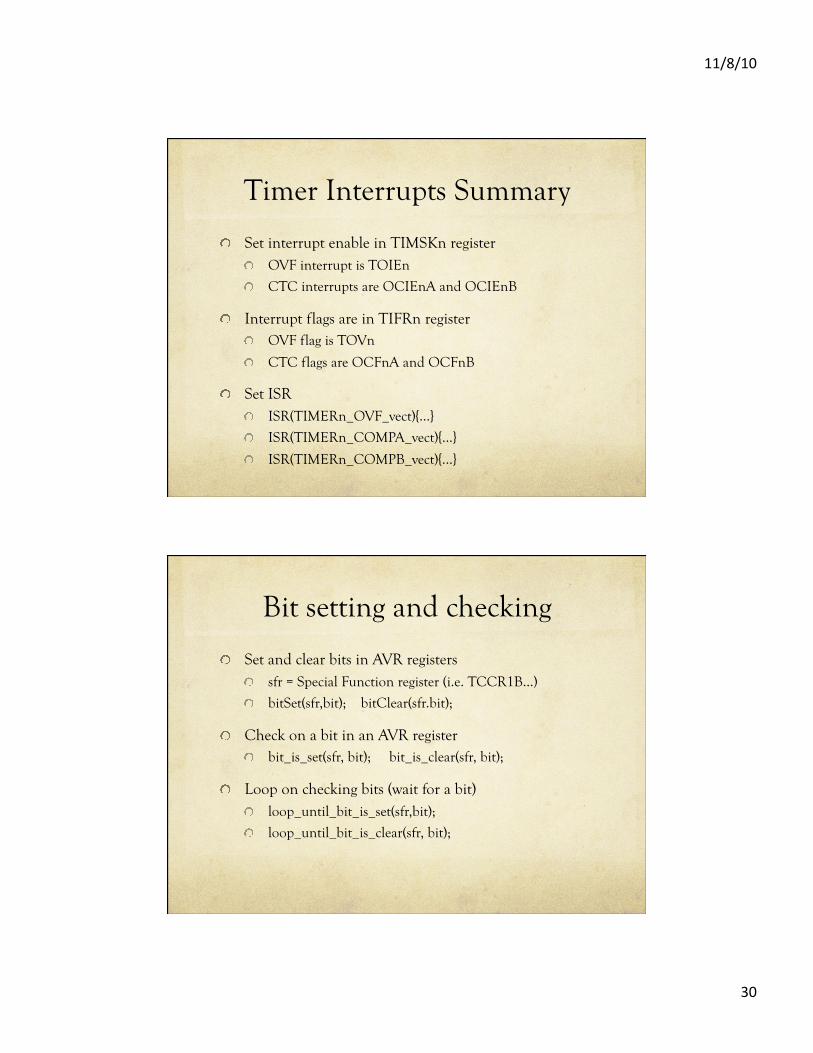
Timer Interrupts Summary
! Set interrupt enable in TIMSKn register ! OVF interrupt is TOIEn
! CTC interrupts are OCIEnA and OCIEnB
! Interrupt flags are in TIFRn register ! OVF flag is TOVn
! CTC flags are OCFnA and OCFnB
! Set ISR ! ISR(TIMERn_OVF_vect){…}
! ISR(TIMERn_COMPA_vect){…}
! ISR(TIMERn_COMPB_vect){…}
Bit setting and checking
! Set and clear bits in AVR registers ! sfr = Special Function register (i.e. TCCR1B…)
! bitSet(sfr,bit); bitClear(sfr.bit);
! Check on a bit in an AVR register ! bit_is_set(sfr, bit); bit_is_clear(sfr, bit);
! Loop on checking bits (wait for a bit) ! loop_until_bit_is_set(sfr,bit);
! loop_until_bit_is_clear(sfr, bit);
11/8/10
31
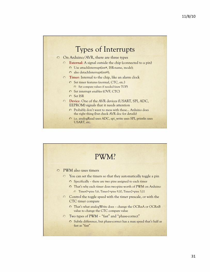
Types of Interrupts ! On Arduino/AVR, there are three types
! External: A signal outside the chip (connected to a pin) ! Use attachInterrupt(int#, ISR-name, mode); ! also detachInterrupt(int#);
! Timer: Internal to the chip, like an alarm clock ! Set timer features (normal, CTC, etc.)
! Set compare values if needed (new TOP)
! Set interrupt enables (OVF, CTC) ! Set ISR
! Device: One of the AVR devices (USART, SPI, ADC, EEPROM) signals that it needs attention ! Probably don’t want to mess with these… Arduino does
the right thing (but check AVR doc for details) ! i.e. analogRead uses ADC, spi_write uses SPI, println uses
USART, etc.
PWM?
! PWM also uses timers ! You can set the timers so that they automatically toggle a pin
! Specifically – there are two pins assigned to each timer
! That’s why each timer does two-pins worth of PWM on Arduino ! Timer0=pins 5,6, Timer1=pins 9,10, Timer2=pins 3,11
! Control the toggle speed with the timer prescale, or with the CTC timer compare ! That’s what analogWrite does – change the OCRnA or OCRnB
value to change the CTC compare value
! Two types of PWM – “fast” and “phase-correct” ! Subtle difference, but phase-correct has a max speed that’s half as
fast as “fast”
11/8/10
32
Final Word
! Interrupts are a wonderful way of reacting to events, or setting things up to happen at specific times or frequencies ! Once they’re set up, they operate on their own without
main-program fussing
! You can also write wonderfully incomprehensible code that uses interrupts!