![Interrupt Priorities Soþuare via Interrupt - USENIX · Setting Interrupt Priorities in Soþuare via Interrupt Queueing Geoff Collyer Bell Laboratories ... [Kernighan & Ritchie 1978]](https://static.fdocuments.net/doc/165x107/5c8a77bf09d3f22e408bf5b1/interrupt-priorities-sobuare-via-interrupt-usenix-setting-interrupt-priorities.jpg)
Interrupt
34
8051 INTERRUPT PROGRAMMING IN ASSEMBLY Prof. Anish Goel
Transcript of Interrupt
8051 INTERRUPT PROGRAMMING IN ASSEMBLY
Prof. Anish Goel
OBJECTIVES
� Contrast and compare interrupts versus polling� Explain the purpose of the ISR (interrupt service routine) � List the 6 interrupts of the 8051� Explain the purpose of the interrupt vector table � Enable or disable 8051 interrupts� Program the 8051 timers using interrupts
2
� Describe the external hardware interrupts of the 8051� Contrast edge-triggered with level-triggered interrupts� Program the 8051 for interrupt-based serial communication� Define the interrupt priority of the 8051
Prof. Anish Goel

8051 INTERRUPTS� Interrupts vs. polling
� on receiving interrupt, the microcontroller interrupts whatever it is doing and executes interrupt service routine (ISR)
� microcontroller can serve many devices� each device gets attention based on the priority� polling wastes time
3
� polling wastes time
Prof. Anish Goel
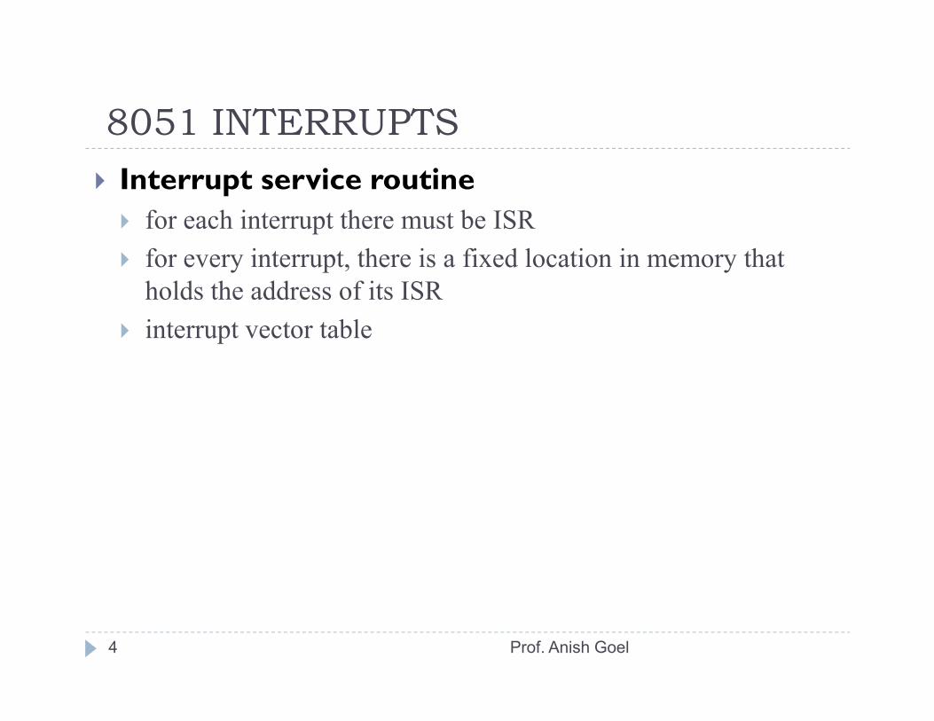
8051 INTERRUPTS� Interrupt service routine
� for each interrupt there must be ISR� for every interrupt, there is a fixed location in memory that holds the address of its ISR
� interrupt vector table
4 Prof. Anish Goel
8051 INTERRUPTS
5
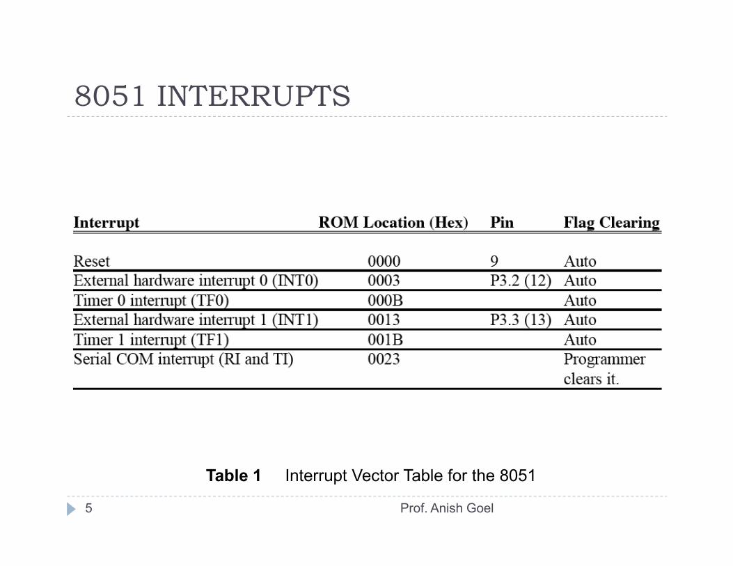
Table 1 Interrupt Vector Table for the 8051
Prof. Anish Goel

8051 INTERRUPTS� Steps in executing an interrupt
1. mC finishes the instruction it is executing and saves the address of the next instruction (PC) on the stack
2. it saves the current status of all the interrupts internally3. it jumps to a fixed location in memory called the interrupt vector
table
6
table4. the microcontroller gets the address of the ISR from the interrupt
vector table and jumps to it and starts to execute the ISR until it reaches the last instruction RETI
5. the microcontroller returns to the place where it was interrupted, it gets the PC address from the stack by popping the top two bytes of the stack into the PC and then it starts to execute from that address
Prof. Anish Goel
8051 INTERRUPTS� Six interrupts in the 8051
� 1 reset interrupt, when the reset pin is activated, the 8051 jumps to address location 0000
� 2 timer interrupts� 2 external hardware interrupts� pin 12 (P3.2) and 13 (P3.3) in port 3 are for the external hardware
interrupts
7
interrupts� 1 serial communication interrupt that belongs to both receive and
transmit� a limited number of bytes is set aside for each interrupt
Prof. Anish Goel
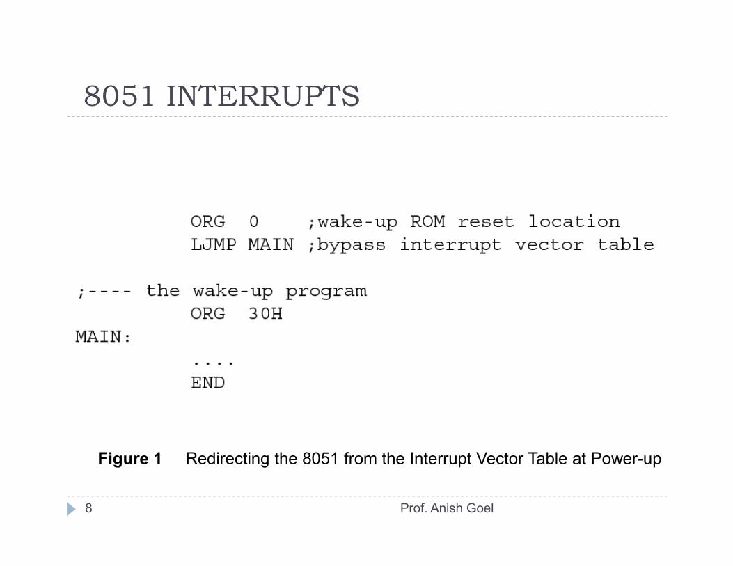
8051 INTERRUPTS
8
Figure 1 Redirecting the 8051 from the Interrupt Vector Table at Power-up
Prof. Anish Goel
8051 INTERRUPTS� Enabling and disabling an interrupt
� upon reset all interrupts are disabled� interrupts must be enabled by software� IE register (interrupt enable) is responsible for enabling and disabling the interrupts
� IE is a bit-addressable register
9
� IE is a bit-addressable register
Prof. Anish Goel
8051 INTERRUPTS� Steps in enabling an interrupt
1. EA must be set to 12. set the relevant bits in IE register to high
� EA = 0, no interrupt will be responded to, even if the relevant bit in the IE register is high
10
relevant bit in the IE register is high
Prof. Anish Goel
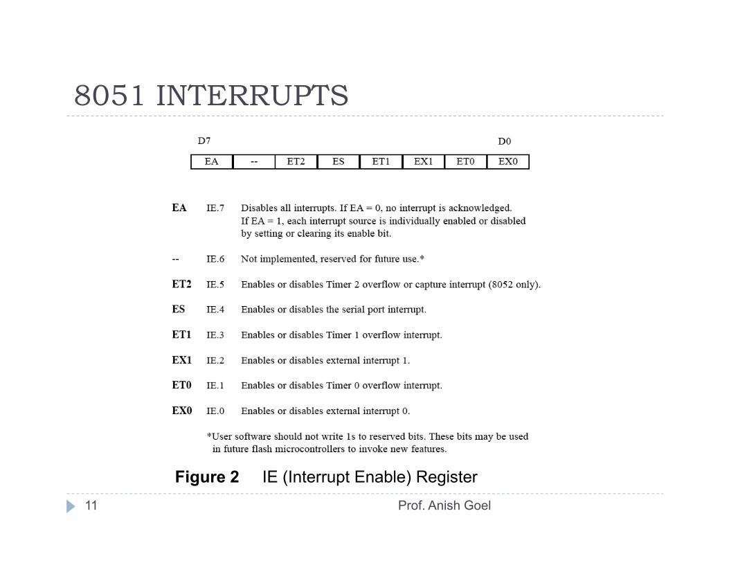
8051 INTERRUPTS
11
Figure 2 IE (Interrupt Enable) Register
Prof. Anish Goel
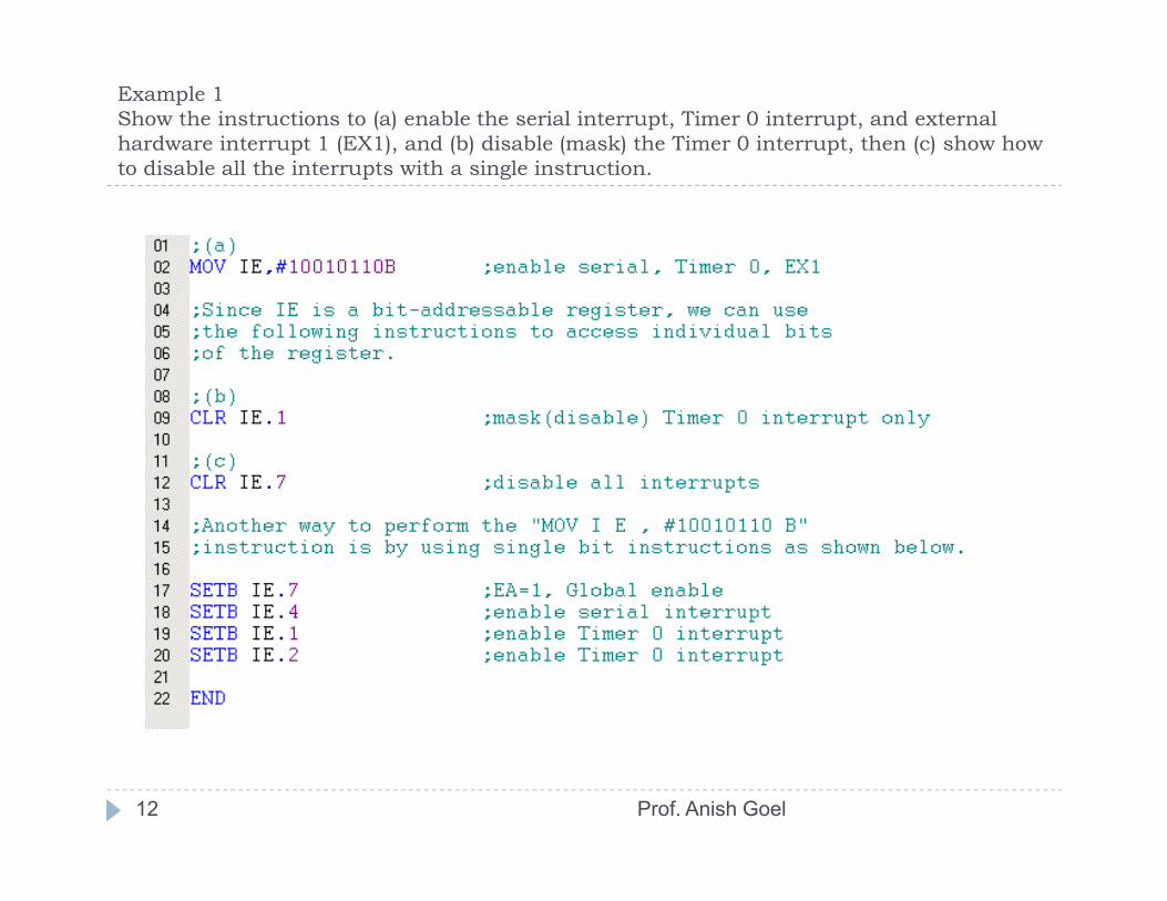
Example 1Show the instructions to (a) enable the serial interrupt, Timer 0 interrupt, and external hardware interrupt 1 (EX1), and (b) disable (mask) the Timer 0 interrupt, then (c) show how to disable all the interrupts with a single instruction.
12 Prof. Anish Goel
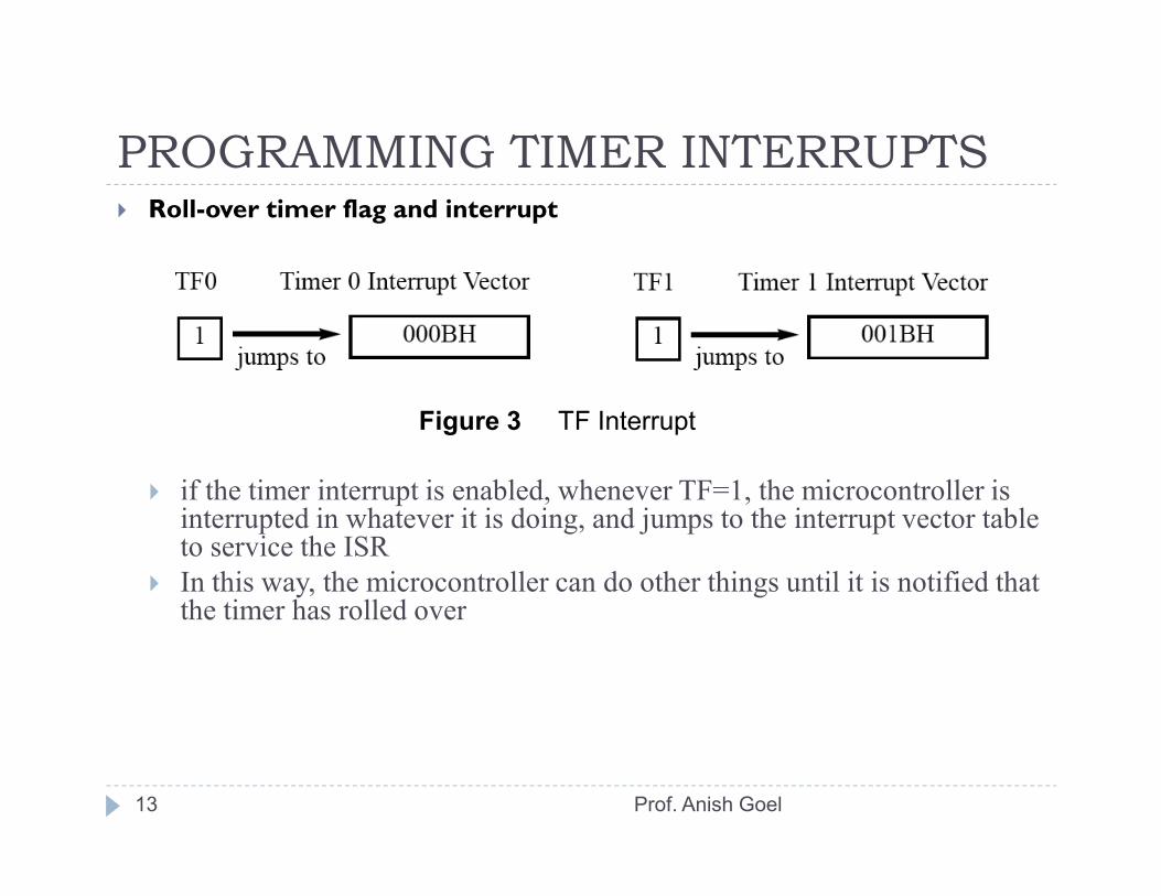
PROGRAMMING TIMER INTERRUPTS� Roll-over timer flag and interrupt
Figure 3 TF Interrupt
13
� if the timer interrupt is enabled, whenever TF=1, the microcontroller is interrupted in whatever it is doing, and jumps to the interrupt vector table to service the ISR
� In this way, the microcontroller can do other things until it is notified that the timer has rolled over
Prof. Anish Goel
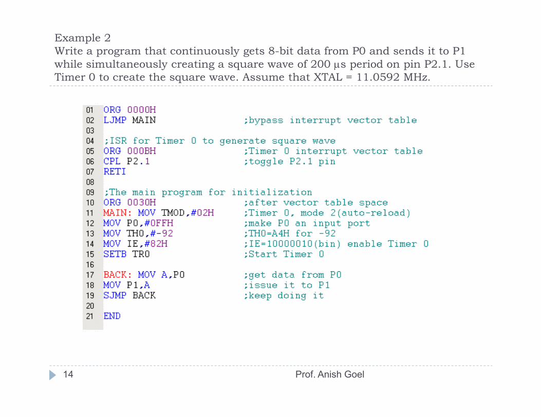
Example 2Write a program that continuously gets 8-bit data from P0 and sends it to P1 while simultaneously creating a square wave of 200 µs period on pin P2.1. Use Timer 0 to create the square wave. Assume that XTAL = 11.0592 MHz.
14 Prof. Anish Goel
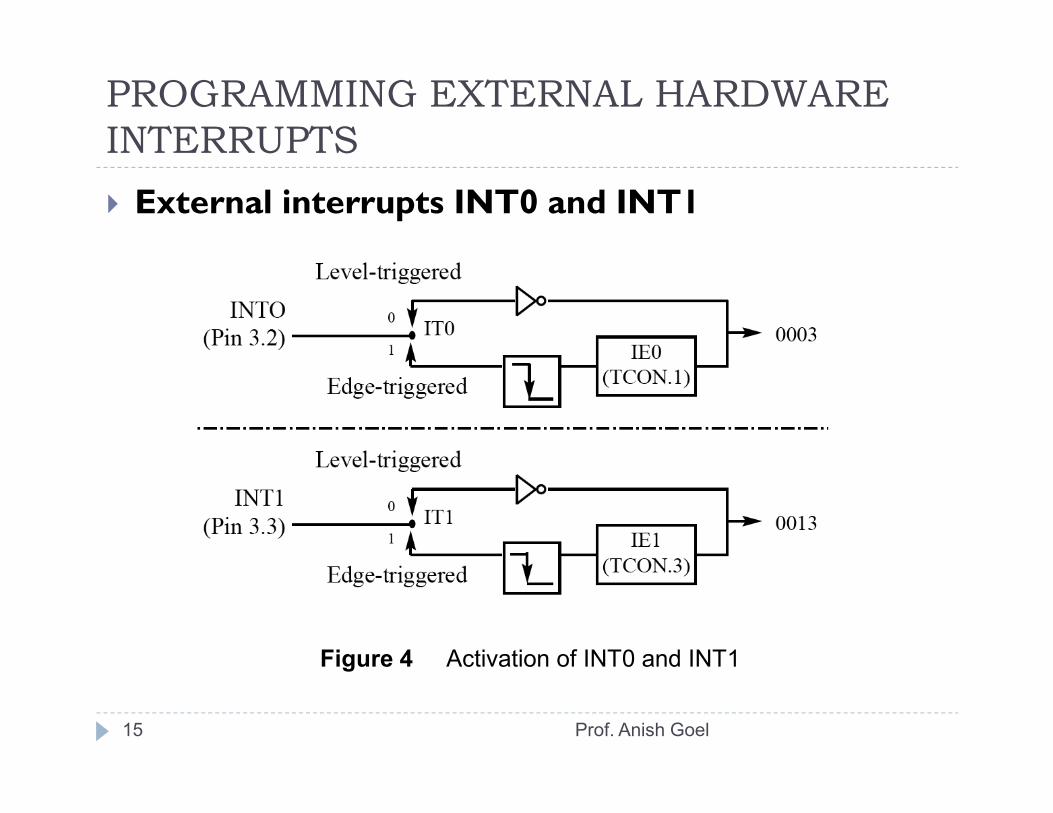
PROGRAMMING EXTERNAL HARDWARE INTERRUPTS
� External interrupts INT0 and INT1
15
Figure 4 Activation of INT0 and INT1
Prof. Anish Goel
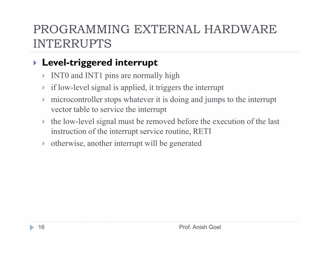
PROGRAMMING EXTERNAL HARDWARE INTERRUPTS� Level-triggered interrupt
� INT0 and INT1 pins are normally high� if low-level signal is applied, it triggers the interrupt� microcontroller stops whatever it is doing and jumps to the interrupt
vector table to service the interrupt� the low-level signal must be removed before the execution of the last
instruction of the interrupt service routine, RETI
16
instruction of the interrupt service routine, RETI� otherwise, another interrupt will be generated
Prof. Anish Goel

Example 5Assume that the INT1 pin is connected to a switch that is normally high. Whenever it goes low, it should turn on an LED. The LED is connected to P1.3 and is normally off. When it is turned on it should stay on for a fraction of a second. As long as the switch is pressed low, the LED should stay on.
17 Prof. Anish Goel
PROGRAMMING EXTERNAL HARDWARE INTERRUPTS
� Sampling the low level-triggered interrupt� to ensure the activation of the hardware interrupt at the INTx pin, make sure that the duration of the low-level signal is around 4 machine cycles
18 Prof. Anish Goel
PROGRAMMING EXTERNAL HARDWARE INTERRUPTS
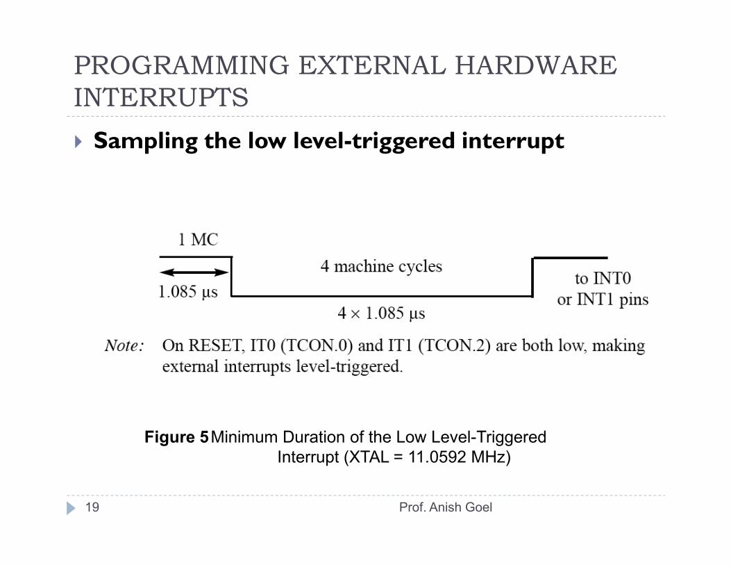
� Sampling the low level-triggered interrupt
19
Figure 5Minimum Duration of the Low Level-TriggeredInterrupt (XTAL = 11.0592 MHz)
Prof. Anish Goel
PROGRAMMING EXTERNAL HARDWARE INTERRUPTS
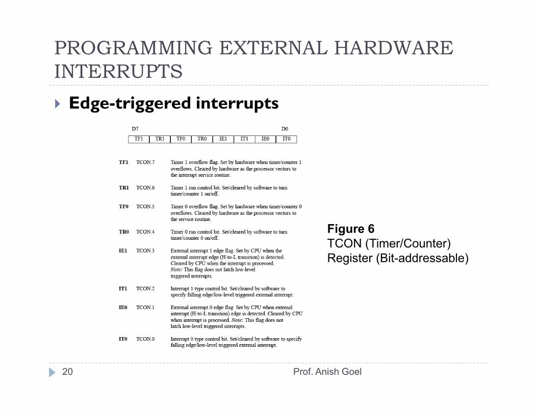
� Edge-triggered interrupts
20
Figure 6TCON (Timer/Counter) Register (Bit-addressable)
Prof. Anish Goel
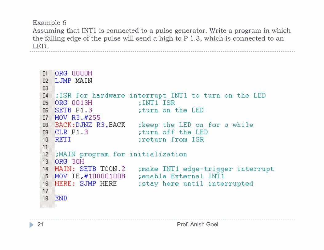
Example 6Assuming that INT1 is connected to a pulse generator. Write a program in which the falling edge of the pulse will send a high to P 1.3, which is connected to an LED.
21 Prof. Anish Goel
PROGRAMMING EXTERNAL HARDWARE INTERRUPTS
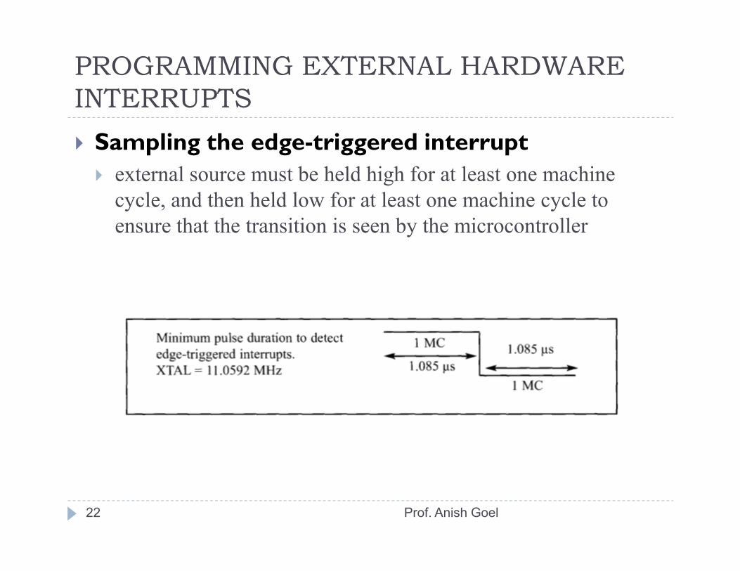
� Sampling the edge-triggered interrupt� external source must be held high for at least one machine cycle, and then held low for at least one machine cycle to ensure that the transition is seen by the microcontroller
22 Prof. Anish Goel
PROGRAMMING EXTERNAL HARDWARE INTERRUPTS
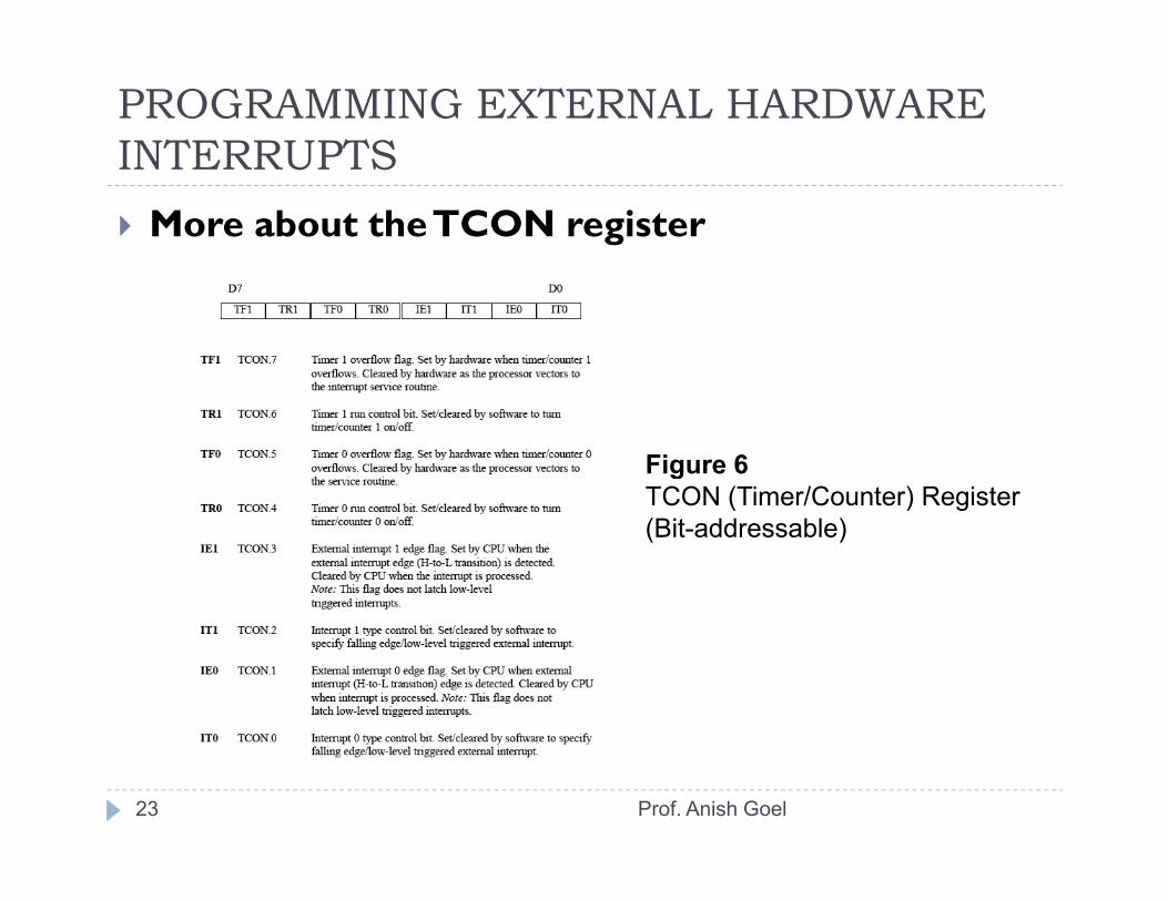
� More about the TCON register
Figure 6
23
Figure 6TCON (Timer/Counter) Register(Bit-addressable)
Prof. Anish Goel

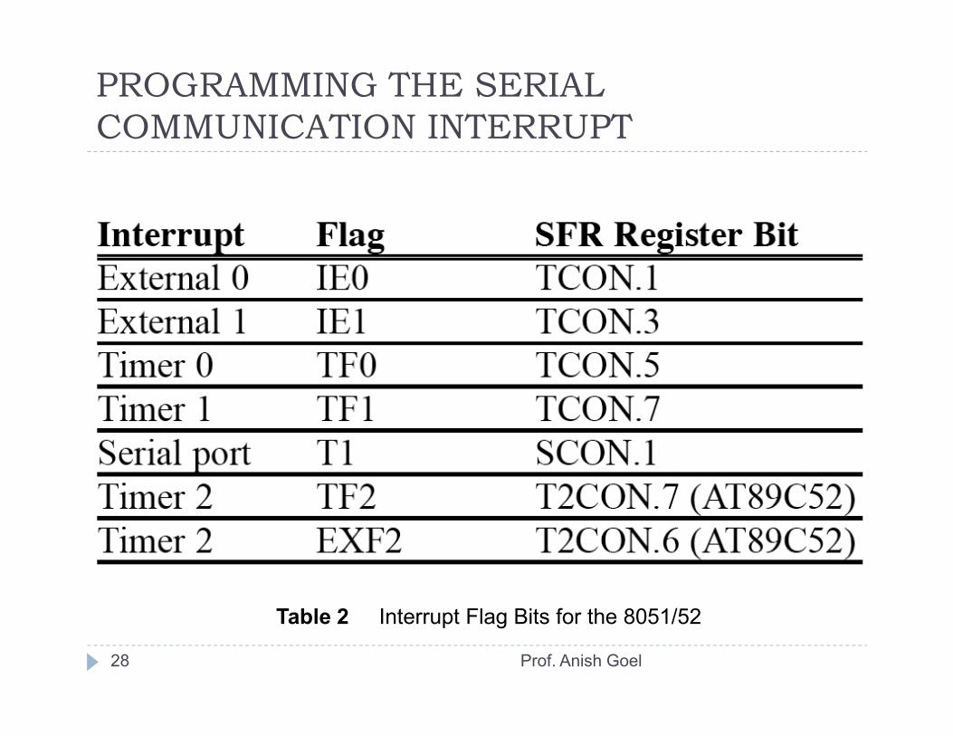
PROGRAMMING THE SERIAL COMMUNICATION INTERRUPT
� RI and TI flags and interrupts� 1 interrupt is set for serial communication� used to both send and receive data� when RI or TI is raised the 8051 gets interrupted and jumps to memory address location 0023H to execute the ISR
� the ISR must examine the TI and RI flags to see which one
24
� the ISR must examine the TI and RI flags to see which one caused the interrupt and respond accordingly
Prof. Anish Goel

PROGRAMMING THE SERIAL COMMUNICATION INTERRUPT
25
Figure 7 Single Interrupt for Both TI and RI
Prof. Anish Goel
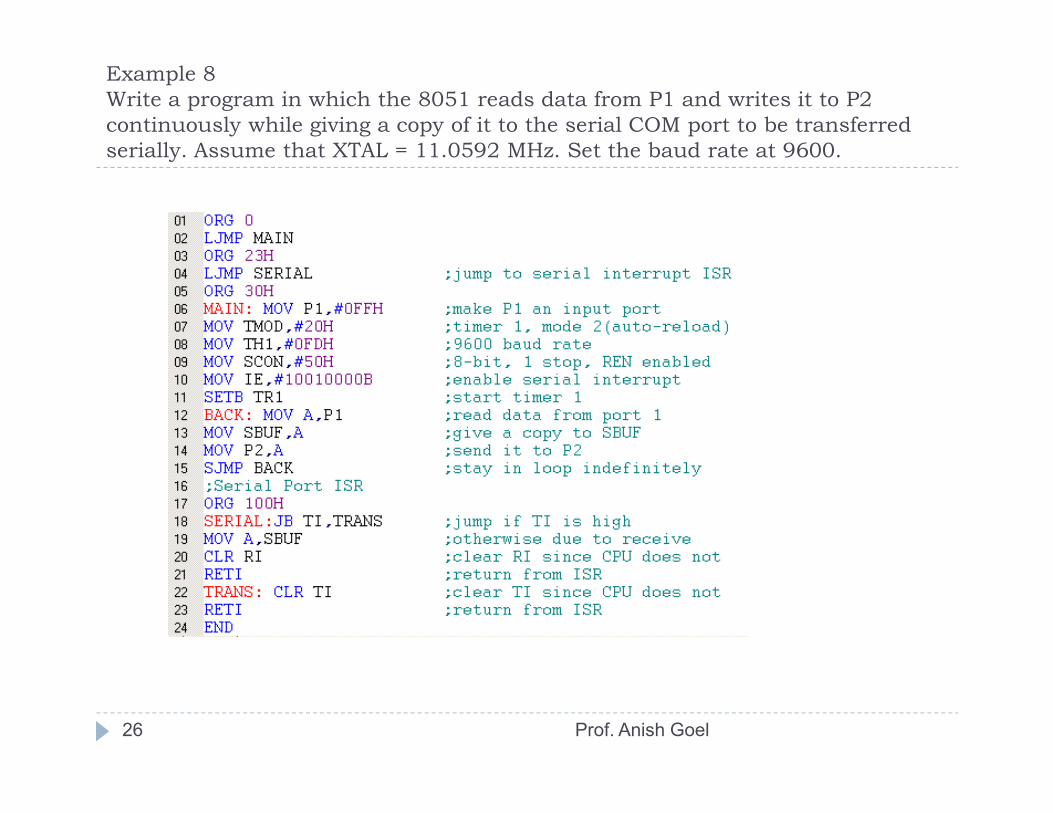
Example 8Write a program in which the 8051 reads data from P1 and writes it to P2 continuously while giving a copy of it to the serial COM port to be transferred serially. Assume that XTAL = 11.0592 MHz. Set the baud rate at 9600.
26 Prof. Anish Goel

Example 9Write a program in which the 8051 gets data from P1 and sends it to P2 continuously while incoming data from the serial port is sent to P0. Assume that XTAL = 11.0592 MHz. Set the baud rate at 9600.
27 Prof. Anish Goel
PROGRAMMING THE SERIAL COMMUNICATION INTERRUPT
28
Table 2 Interrupt Flag Bits for the 8051/52
Prof. Anish Goel

Example 10Write a program using interrupts to do the following: (a) Receive data serially and send it to P0, (b) Have port P1 read and transmitted serially, and a copy given to P2, (c) Make Timer 0 generate a square wave of 5 kHz frequency on P0.1. Assume that XTAL = 11.0592 MHz. Set the baud rate at 4800.
29 Prof. Anish Goel
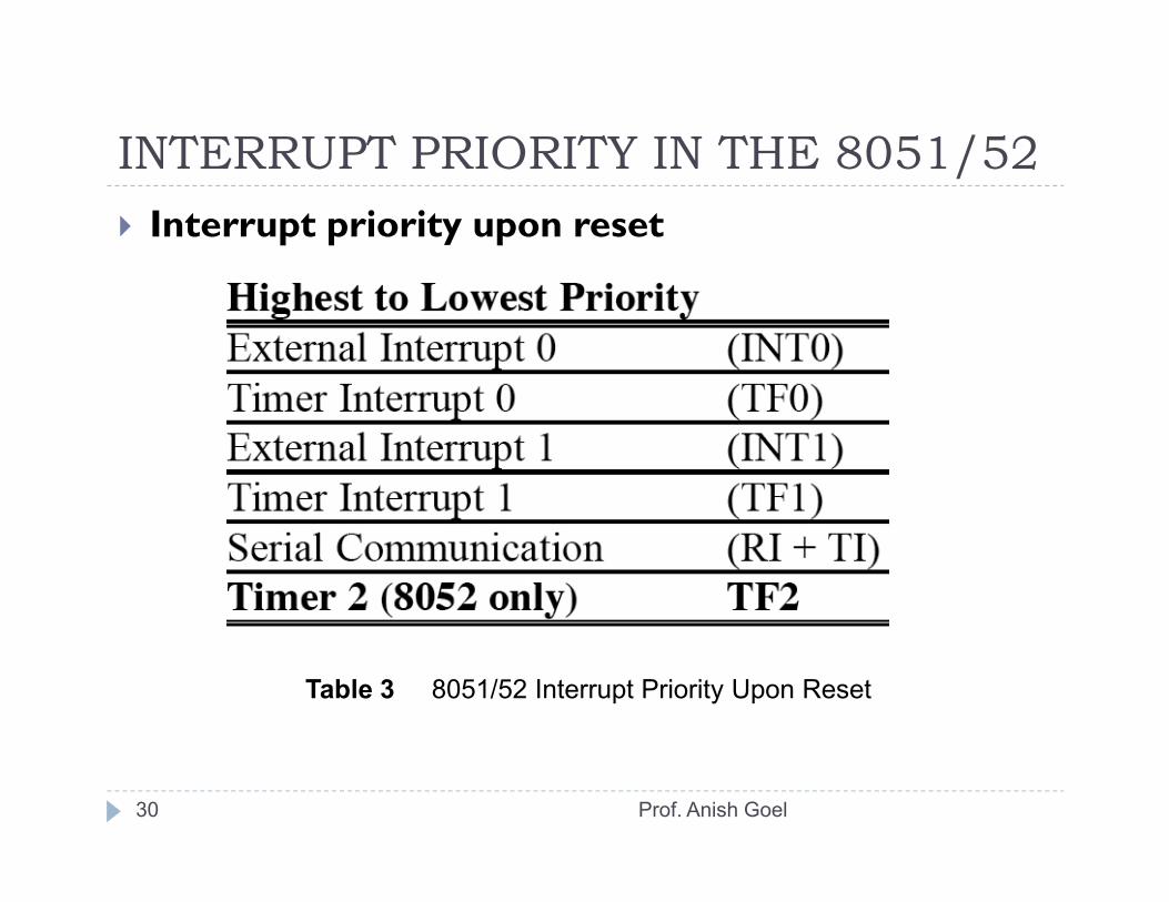
INTERRUPT PRIORITY IN THE 8051/52� Interrupt priority upon reset
30
Table 3 8051/52 Interrupt Priority Upon Reset
Prof. Anish Goel
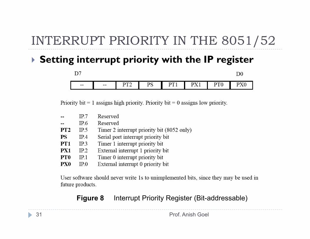
INTERRUPT PRIORITY IN THE 8051/52� Setting interrupt priority with the IP register
31
Figure 8 Interrupt Priority Register (Bit-addressable)
Prof. Anish Goel

Example 12(a)Program the IP register to assign the highest priority to INT 1, then (b) discuss what happens if INT0, INT1, and TF0are activated at the same time. Assume that the interrupts are both edge-triggered.
� (a) MOV IP,#00000100B or "SETB IP.2“
� (b) when INT0, INT1, and TF0 interrupts are activated at the same time, the 8051 services INT1 first, then it services INT0, then TF0
32 Prof. Anish Goel
INTERRUPT PRIORITY IN THE 8051/52� Interrupt inside an interrupt
� what happens if the 8051 is executing an ISR belonging to an interrupt and another interrupt is activated?
� a high-priority interrupt can interrupt a low-priority interrupt� no low-priority interrupt can get the immediate attention of the CPU until it has finished servicing the high-priority interrupts
33
CPU until it has finished servicing the high-priority interrupts
Prof. Anish Goel
INTERRUPT PRIORITY IN THE 8051/52� Triggering the interrupt by software
� can test an ISR with instructions to set the interrupts high� "SETB TF1" will interrupt the 8051 in whatever it is doing and force it to jump to the interrupt vector table
� don’t have to wait for Timer 1 to roll over� useful for testing ISR
34
� useful for testing ISR
Prof. Anish Goel