Interoperability Test Plan for LTE Wireless Devices · Section 2 Basic LTE Attach ... 4.1 Idle Mode...
102
February 2017 1 Version 2.1 Interoperability Test Plan for LTE Wireless Devices Version 2.1 February 2017 © 2017 CTIA - The Wireless Association ® . All rights reserved. CTIA hereby grants to CTIA Authorized Testing Laboratories (CATLs), and only to CATLs, a limited, non- transferable license to use this Test Plan for the sole purpose of testing wireless devices for the CTIA Certification Program, and to reproduce this Test Plan for internal use only. Any other use of this Test Plan must be authorized in writing by CTIA. Any reproduction or transmission of all or part of this Test Plan, in any form or by any means, electronic or mechanical, including photocopying, recording, or via any information storage and retrieval system, without the prior written permission of CTIA, is unauthorized and strictly prohibited. Any reproduction of this Test Plan shall display the notice: "Copyright by CTIA. All rights reserved."
-
Upload
truonghanh -
Category
Documents
-
view
228 -
download
3
Transcript of Interoperability Test Plan for LTE Wireless Devices · Section 2 Basic LTE Attach ... 4.1 Idle Mode...
February 2017 1 Version 2.1
Interoperability Test Plan for LTE Wireless Devices
Version 2.1
February 2017
© 2017 CTIA - The Wireless Association®. All rights reserved.
CTIA hereby grants to CTIA Authorized Testing Laboratories (CATLs), and only to CATLs, a limited, non-transferable license to use this Test Plan for the sole purpose of testing wireless devices for the CTIA Certification Program, and to reproduce this Test Plan for internal use only. Any other use of this Test Plan must be authorized in writing by CTIA.
Any reproduction or transmission of all or part of this Test Plan, in any form or by any means, electronic or mechanical, including photocopying, recording, or via any information storage and retrieval system, without the prior written permission of CTIA, is unauthorized and strictly prohibited.
Any reproduction of this Test Plan shall display the notice: "Copyright by CTIA. All rights reserved."

February 2017 2 Version 2.1
CTIA Certification Program 1400 16th Street, NW
Suite 600 Washington, DC 20036
1.202.785.0081
www.ctia.org/certification
February 2017 3 Version 2.1
Table of Contents Section 1 Introduction .......................................................................................................................... 8
1.1 Purpose ................................................................................................................................. 8 1.2 Scope ..................................................................................................................................... 8 1.3 References ............................................................................................................................ 8 1.4 Glossary ................................................................................................................................ 9 1.5 Basic Lab Configuration .................................................................................................... 11
Section 2 Basic LTE Attach ................................................................................................................ 12 2.1 Cell Acquisition (PSS/SSS/MIB Decode) .......................................................................... 12 2.2 SIB Decoding ...................................................................................................................... 12 2.3 UE RACH Procedure .......................................................................................................... 13 2.4 Initial RRC Connection Setup and Reconfiguration ....................................................... 13 2.5 Attach Procedure with Various NAS Security Settings and Default Bearer Setup
Procedure ............................................................................................................................ 15 2.6 AS Security ......................................................................................................................... 16
Section 3 Network Access Test Cases ............................................................................................. 18 3.1 Attach Reject, Cause #7 "EPS Services Not Allowed" ................................................... 18 3.2 Attach Reject, Cause #14 "EPS Services Not Allowed in this PLMN" - Multiple PLMN
Environment ....................................................................................................................... 18 3.3 Attach Reject, Cause #11 "PLMN Not Allowed" .............................................................. 19 3.4 Attach Reject, Cause #3 "Illegal UE" ................................................................................ 20 3.5 Attach Reject – Cause Code #15 (No Suitable Cells in Tracking Area) ........................ 21 3.6 Attach Reject – Cause Code #6 (Illegal ME) .................................................................... 22 3.7 Attach Reject – Cause Code # 12 (Tracking Area Not Allowed) .................................... 23 3.8 Tracking Area Update Reject, Cause Code #3 (Illegal UE) ............................................. 24 3.9 Detach - With Power-off ..................................................................................................... 25 3.10 Detach - Without Powering-off .......................................................................................... 26 3.11 Successful Normal Tracking Area Update without ISR activation ................................ 27 3.12 Periodic Tracking Area Update; Successful.................................................................... 28 3.13 Network Selection - Manual Mode – Network on Forbidden List .................................. 30 3.14 Network Selection - Manual Mode – Empty Preferred PLMN List ................................. 30 3.15 Network Selection -– Manual Mode – More than 32 Entries on Preferred PLMN List . 31 3.16 Network Selection – Selection Mode Following Switch off – Manual Network
Selection ............................................................................................................................. 32 3.17 Network Selection – Selection Mode Following Switch off – Automatic Network
Selection ............................................................................................................................. 32 Section 4 Intra-LTE Mobility (Intra-Freq) ........................................................................................... 34
February 2017 4 Version 2.1
4.1 Idle Mode E-UTRA Intra-Frequency Reselection ............................................................ 34 4.2 E-UTRA Handover, Default Ipv4 Bearer – Intra eNodeB Handover ............................... 35 4.3 E-UTRA Handover, Default Ipv4 Bearer – X2 Based ....................................................... 35 4.4 E-UTRA Handover, Default Ipv4 Bearer – S1 Based ....................................................... 36 4.5 E-UTRA Handover, Default Ipv4 Bearer – Inter-MME ...................................................... 37 4.6 E-UTRA Handover, Default Ipv6 Bearer – Intra eNodeB Handover ............................... 38 4.7 E-UTRA Handover, Default Ipv6 Bearer – X2 Based ....................................................... 39 4.8 E-UTRA Handover, Default Ipv6 Bearer – S1 Based ....................................................... 40 4.9 E-UTRA Handover, Default Ipv6 Bearer – Inter-MME ...................................................... 41 4.10 E-UTRA Handover, Dual Ipv6/Ipv4 Bearer – X2 Based ................................................... 42 4.11 E-UTRA Handover, Dual Ipv6/Ipv4 Bearer – S1 Based ................................................... 43 4.12 Intra-freq Intra-LTE Automatic Neighbor Relations Function........................................ 44
Section 5 Intra-LTE Mobility (Inter-Freq) ........................................................................................... 45 5.1 Idle Mode E-UTRA Inter-Frequency Intra-Band (Same BW) Reselection ..................... 45 5.2 Idle Mode E-UTRA Inter-Frequency Intra-Band Inter-BW Reselection ......................... 46 5.3 Idle Mode E-UTRA Inter-Frequency Inter-Band (Same BW) Reselection ..................... 46 5.4 Idle Mode E-UTRA Inter-Frequency Inter-Band Inter-BW Reselection ......................... 47 5.5 E- UTRA Handover (with measurements), Inter-Frequency Intra-Band (same BW) –
Default Bearer with Data Transfer .................................................................................... 48 5.6 E-UTRA Handover (with Measurements), Inter-Frequency Intra-Band Inter-BW –
Default Bearer with Data Transfer .................................................................................... 49 5.7 E- UTRA Handover (with Measurements), Inter-Frequency Inter-Band (Same BW) –
Default Bearer with Data Transfer .................................................................................... 50 5.8 E- UTRA Handover (with Measurements), Inter-Frequency Inter-Band Inter-BW –
Default Bearer with Data Transfer .................................................................................... 51 5.9 Inter-freq Intra-LTE Automatic Neighbor Relations Function........................................ 52
Section 6 System Loss and State Transition ................................................................................... 54 6.1 System Lost – LTE System Lost in RRC_IDLE ............................................................... 54 6.2 System Lost – LTE System Lost in RRC_ACTIVE .......................................................... 54 6.3 Transition – Idle to Active Transition – Service Request ............................................... 55 6.4 Transition – Idle to Active Transition – Paging ............................................................... 56
Section 7 PS Data ................................................................................................................................ 57 7.1 Ipv4 – Without Mobility – SIMO Delay of Ping ................................................................. 57 7.2 Ipv4 – Without Mobility – Transmit diversity (MIMO) Delay of Ping .............................. 57 7.3 Ipv4 – Without Mobility – Open Loop Multiplexing – Delay of Ping .............................. 58 7.4 Ipv4 – Without Mobility – Close Loop Multiplexing – Delay of Ping ............................. 59 7.5 Ipv6 – Without Mobility – SIMO Delay of Ping ................................................................. 60
February 2017 5 Version 2.1
7.6 Ipv6 – Without Mobility – Transmit Diversity (MIMO) Delay of Ping ............................. 60 7.7 Ipv6 – Without Mobility – Open Loop Multiplexing – Delay of Ping .............................. 61 7.8 Ipv6 – Without Mobility – Close Loop Multiplexing – Delay of Ping ............................. 62 7.9 PDN Connectivity Request –ESM Information transfer flag=TRUE .............................. 63 7.10 PDN Connectivity Reject, ESM Cause #27 Missing or Unknown APN ......................... 65 7.11 PDN Disconnect Procedure – UE Initiated....................................................................... 66 7.12 Detach Procedure – Network Initiated ............................................................................. 66 7.13 Multiple PDN Connections – Second PDN Connectivity Request (UE Initiated) ......... 67 7.14 Multiple PDN Connections – Second PDN Connectivity Disconnect ........................... 69 7.15 Detach Procedure – UE Initiated ....................................................................................... 70 7.16 HTTP Browsing ................................................................................................................... 70
Section 8 Peak Throughput Validation with Different PDSCH Transmission Mode ..................... 72 8.1 DL UDP Data Transfer in SIMO with Default Ipv4 Bearer ............................................... 72 8.2 DL UDP Data Transfer in Tx Diversity with Default Ipv4 Bearer .................................... 73 8.3 DL UDP Data Transfer in Open Loop MIMO (TM=3) with Default Ipv4 Bearer ............. 73 8.4 DL UDP Data Transfer in Close Loop MIMO (TM=4) with Default Ipv4 Bearer ............. 74 8.5 DL FTP Data Transfer in SIMO with Default Ipv4 Bearer ................................................ 74 8.6 DL FTP Data Transfer in Tx Diversity with Default Ipv4 Bearer..................................... 75 8.7 DL FTP Data Transfer in Open Loop MIMO (TM=3) with Default Ipv4 Bearer .............. 75 8.8 DL FTP Data Transfer in Close Loop MIMO (TM=4) with Default Ipv4 Bearer .............. 76 8.9 UL UDP Data Transfer with Default Ipv4 Bearer ............................................................. 76 8.10 UL FTP Data Transfer with Default Ipv4 Bearer .............................................................. 77 8.11 DL UDP Data Transfer in SIMO with Default Ipv6 Bearer ............................................... 77 8.12 DL UDP Data Transfer in Tx Diversity with Default Ipv6 Bearer .................................... 77 8.13 DL UDP Data Transfer in Open Loop MIMO (TM=3) with Default Ipv6 Bearer ............. 78 8.14 DL UDP Data Transfer in Close Loop MIMO (TM=4) with Default Ipv6 Bearer ............. 78 8.15 DL FTP Data Transfer in SIMO with Default Ipv6 Bearer ................................................ 79 8.16 DL FTP Data Transfer in Tx Diversity with Default Ipv6 Bearer..................................... 79 8.17 DL FTP Data Transfer in Open Loop MIMO (TM=3) with Default Ipv6 Bearer .............. 80 8.18 DL FTP Data Transfer in Close Loop MIMO (TM=4) with Default Ipv6 Bearer .............. 80 8.19 UL UDP Data Transfer with Default Ipv6 Bearer ............................................................. 81 8.20 UL FTP Data Transfer with Default Ipv6 Bearer .............................................................. 81
Section 9 Dedicated Bearer ................................................................................................................ 82 9.1 Network Initiated Dedicated Ipv4 Bearer Establishment and Data Connectivity......... 82 9.2 Network Initiated Dedicated Ipv6 Bearer Establishment and Data Connectivity......... 82
Section 10 DRX ...................................................................................................................................... 84
February 2017 6 Version 2.1
10.1 Long and Short DRX .......................................................................................................... 84 Section 11 TDD Specific Test Cases ................................................................................................... 85
11.1 Simultaneous UL and DL Data throughput with Default IPV4 Bearer ........................... 85 11.2 Simultaneous UL and DL Data throughput with Default IPV6 Bearer ........................... 85 11.3 E-UTRA Handover, Default IPV4 Bearer – X2 BASED Between Frame Config (1:3) and
Frame Config (2:3) (Ipv4 Bearer is Used) ........................................................................ 86 11.4 E-UTRA Handover, Default IPV6 Bearer – X2 BASED Between Frame Config (1:3) and
Frame Config (2:3) (Ipv6 Bearer is Used) ......................................................................... 87 11.5 E-UTRA Handover, Default IPV4 Bearer (With Measurements), Inter-Frequency – S1
Based Between Frame Config (1:4) and Frame Config (2:4) (Ipv4 Bearer is Used) .... 88 11.6 E-UTRA Handover, Default IPV4 Bearer (With Measurements), Inter-Frequency – S1
Based between Frame Config (1:9) and Frame Config (2:9) (Ipv6 Bearer is Used) ..... 89 Section 12 Level 2 Test Cases ............................................................................................................. 91 Section 13 Level 1 Test Cases ............................................................................................................. 95 Section 14 Basic Test Cases ................................................................................................................ 99 Appendix A Device Checklist and UE Information Summary ........................................................... 101
A.1 Checklist Document ......................................................................................................... 101 Appendix B Revision History ............................................................................................................... 102
February 2017 7 Version 2.1
List of Figures
Figure 1.5-1 Basic Lab Configuration ............................................................................................................................ 11
List of Tables
Table 1.4-1 Glossary ............................................................................................................................................................ 9
Table 2.5-1 NAS Security Settings .................................................................................................................................. 16
Table 2.6-1 AS Security Settings ..................................................................................................................................... 17
Table 8.1-1 Transmission Modes Specification ............................................................................................................. 72
Table 12.1-1 Level 2 Test Cases ...................................................................................................................................... 91
Table 13.1-1 Level 1 Test Cases ...................................................................................................................................... 95
Table 14.1-1 Basic Test Cases ......................................................................................................................................... 99
February 2017 8 Version 2.1
Section 1 Introduction
1.1 Purpose
The purpose of this document is to define the CTIA Certification Program test requirements for LTE interoperability. Test requirements are applicable to both FDD and TDD supported bands and bandwidths.
1.2 Scope
This document provides cabled interoperability testing for UE and networks supporting E-UTRA as defined by 3GPP. This document includes relevant protocol related testing as well as functional testing required for interoperability requirements. This testing is intended to be performed in an infrastructure vendor test lab, and includes multimode (FDD and/or TDD).
Cabled Interoperability tests are referenced from 3GPP test specifications. All tests listed shall be included as line items in the Cabled Interoperability Test Report.
Cabled Interoperability testing is divided into two levels:
• Level 2 Cabled IOT
• Level 1 Cabled IOT
Level 2 Cabled Interoperability Testing
Level 2 Cabled IOT Testing is a comprehensive verification effort which determines the interoperability of a device prior to being released.
Level 1 Cabled Interoperability Testing
Level 1 Cabled IOT Testing is defined as a reduced set of test cases from Level 2. This level of testing is used for regression verification and / or certifying a device based on target market requirements.
1.3 References
The following documents are referenced in this test plan:
Official Document TS.11: Device Field and Lab Test Guidelines, Version 18, 30th November, 2016, GSM Association.
TS 24.301: Non-Access-Stratum (NAS) protocol for Evolved Packet System (EPS); Stage 3, 3GPP.
TS 36.211: Evolved Universal Terrestrial Radio Access (E-UTRA); Physical Channels and Modulation, 3GPP.
TS 36.213: Evolved Universal Terrestrial Radio Access (E-UTRA); Physical Layer Procedures, 3GPP.
TS 36.300: Evolved Universal Terrestrial Radio Access (E-UTRA) and Evolved Universal Terrestrial Radio Access Network (E-UTRAN); Overall description; Stage 2, 3GPP.
TS 36.306: Evolved Universal Terrestrial Radio Access (E-UTRA); User Equipment (UE) radio access capabilities, 3GPP
February 2017 9 Version 2.1
TS 36.331: Evolved Universal Terrestrial Radio Access (E-UTRA); Radio Resource Control (RRC); Protocol specification, 3GPP
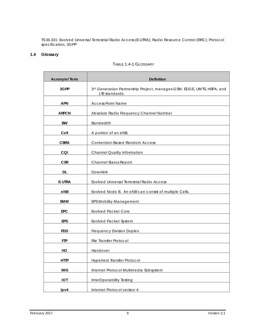
1.4 Glossary
TABLE 1.4-1 GLOSSARY
Acronym/Term Definition
3GPP 3rd Generation Partnership Project, manages GSM, EDGE, UMTS, HSPA, and LTE standards
APN Access Point Name
ARFCN Absolute Radio Frequency Channel Number
BW Bandwidth
Cell A portion of an eNB.
CBRA Contention-Based Random Access
CQI Channel Quality Information
CSR Channel Status Report
DL Downlink
E-UTRA Evolved Universal Terrestrial Radio Access
eNB Evolved Node B. An eNB can consist of multiple Cells.
EMM EPS Mobility Management
EPC Evolved Packet Core
EPS Evolved Packet System
FDD Frequency Division Duplex
FTP File Transfer Protocol
HO Handover
HTTP Hypertext Transfer Protocol
IMS Internet Protocol Multimedia Subsystem
IOT InterOperability Testing
Ipv4 Internet Protocol version 4
February 2017 10 Version 2.1
Acronym/Term Definition
Ipv6 Internet Protocol version 6
LTE Long Term Evolution
MCS Modulation Code Scheme
MIB Master Information Block
Mbps Mega Bits Per Second
NAS Non Access Stratum
OLSM Open Loop Spatial Multiplexing
CLSM Close Loop Spatial Multiplexing
PDN Packet Data Network
PBCH Physical Broadcast Channel
PDSCH Physical Downlink Shared Channel
PLMN Public Land Mobile Network
PRB Physical Resource Blocks
PSS Primary Synchronization Signal
QAM Quadrature Amplitude Modulation
QPSK Quadrature Phase Shift Keying
RAN Radio Access Network
RNTI Radio Network Temporary Identifier
SIB System Information Block
SSS Secondary Synchronization Signal
SIMO Single Input Multiple Output
TDD Time Division Duplex
UDP User Datagram Protocol
UE User Equipment
UL Uplink
February 2017 11 Version 2.1
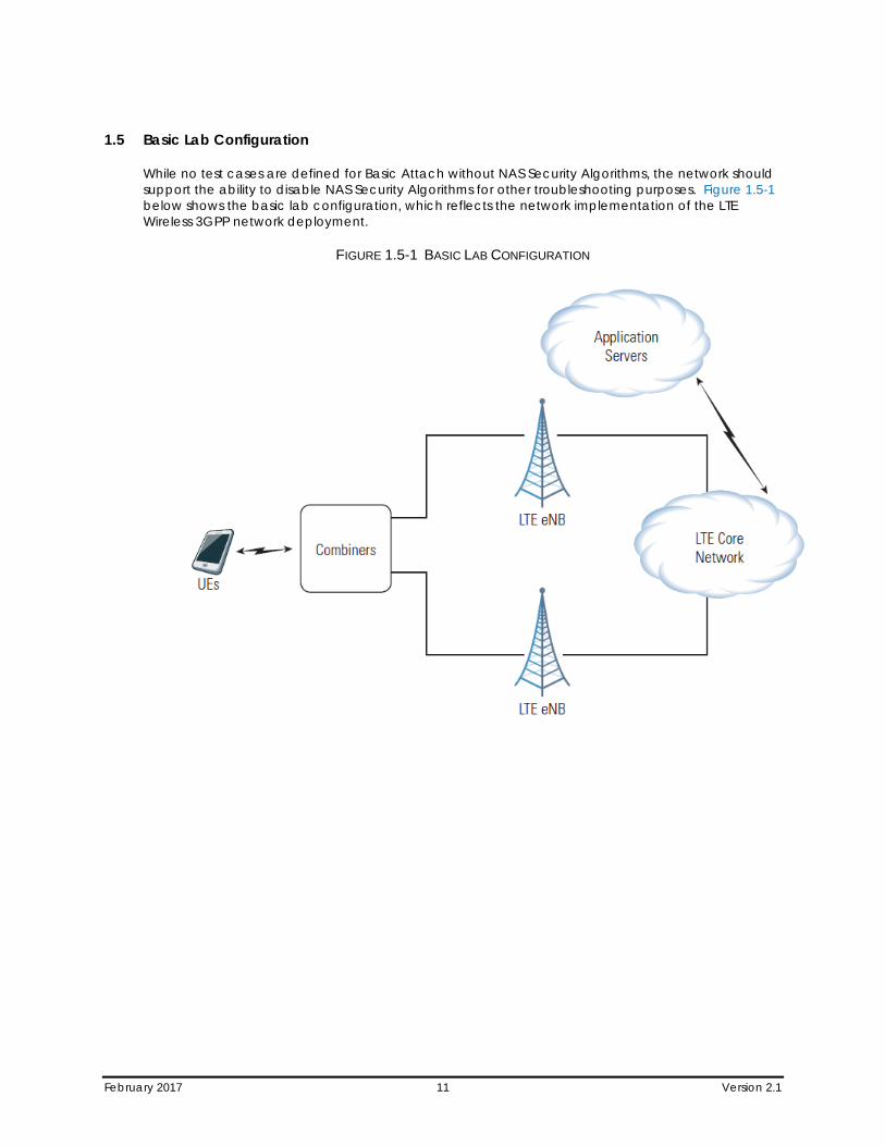
1.5 Basic Lab Configuration
While no test cases are defined for Basic Attach without NAS Security Algorithms, the network should support the ability to disable NAS Security Algorithms for other troubleshooting purposes. Figure 1.5-1 below shows the basic lab configuration, which reflects the network implementation of the LTE Wireless 3GPP network deployment.
FIGURE 1.5-1 BASIC LAB CONFIGURATION
February 2017 12 Version 2.1
Section 2 Basic LTE Attach
This section explicitly tests some of the procedures required for initial system acquisition and device access.
2.1 Cell Acquisition (PSS/SSS/MIB Decode)
The UE shall successfully decode the PSS, SSS and PBCH channels.
Reference:
• 3GPP2 TS 36.211, chapter 6.10 & 6.11
• 3GPP2 TS 36.213, chapter 4.1
• 3GPP2 TS 36.101
• 3GPP2 TS 36.331, chapter 5.2 & 6.2.2
Purpose:
To verify the UE can acquire radio synchronization and the physical layer identity of the cell.
Initial Configuration:
1. The UE is powered off.
2. The cell is unlocked and transmitting PSS, SSS, MIB and downlink cell specific reference signals. The UE shall not have saved a valid copy of MIB prior to execution of the test case otherwise the acquisition procedure may not be triggered.
Procedure:
1. Power on the UE.
Compliance:
The UE has acquired the cell ID correctly, stays synchronized to the cell and the MIB in correctly acquired.
2.2 SIB Decoding
The UE shall successfully decode the SIB1, SIB2, SIB3, SIB4 and SIB5 information.
Reference:
• 3GPP2 TS 36.331, chapter 5.2 & 6.2.2
Purpose:
To verify the UE can acquire all of the SIBs transmitted on the PDSCH by the eNB.
Initial Configuration:
February 2017 13 Version 2.1
1. The cell is unlocked and SIB1, SIB2, SIB3, SIB4 and SIB5 are being transmitted.
2. The UE shall not have saved a valid copy of SIB1, SIB2, SIB3, SIB4 or SIB5 prior to execution of the test case, otherwise the acquisition procedure may not be triggered.
Procedure:
1. Power on the UE and verify that the UE initiates the cell acquisition procedure.
Compliance:
The UE has successfully acquired the SIB1, SIB2, SIB3, SIB4 and SIB5 information.
2.3 UE RACH Procedure
The UE shall successfully perform the initial access of the network.
Reference:
• 3GPP TS 36.321, chapter 5.1 & 6.1.5
Purpose:
To verify the UE can successfully complete all steps in the CBRA RACH procedure.
Initial Configuration:
1. Verify the UE has successfully detected a cell and acquired the required System Information in order to perform random access in the cell.
2. UE has no valid Cell RNTI (C-RNTI).
Procedure:
1. Verify the UE performs random access in the cell.
Compliance:
1. The UE is connected through MAC and is known in eNB by a new unique C-RNTI.
2. The UL Synchronization status of the UE in eNB is in-sync.
2.4 Initial RRC Connection Setup and Reconfiguration
The UE shall successfully perform the “EPS Attach” and “Default EPS Bearer Context Activation” procedures.
Reference:
TS.11 (30.1.1.1); 3GPP TS 24.301

February 2017 14 Version 2.1
Purpose:
To verify, that the UE can successfully establish a default EPS bearer during the Network Attachment procedure.
Initial Configuration:
1. UE is powered off.
Procedure:
1. Power on the UE and verify that the UE initiates the Attach procedure by sending the “Attach Request” message if possible use a diagnostic tool to verify that this message contains the “PDN CONNECTIVITY REQUEST” to the eNodeB. The message may also contain the old GUTI.
2. The network shall respond to the UE with an “RRCConnectionReconfiguration” [ATTACH ACCEPT] message that contains the “EPS Radio Bearer Identity” and the APN for a default bearer.
3. Verify that the UE is attached and has a default EPS bearer by setting up a mobile terminated connection. If the UE is not capable to set-up a mobile terminated service, verify that the UE is attached and has a default EPS bearer by setting up a mobile originated connection without establishing a redundant Tracking Area Update procedure.
Compliance:
1. The UE successfully performs the Attach procedure.
2. The UE establishes a mobile terminated service connection or a mobile originated service connection.
Example message flow:
Step Direction UE – NW Message Comments
1 RRCConnectionRequest RRC
2 RRCConnectionSetup RRC
3 RRCConnectionSetupComplete(ATTACH REQUEST(PDN CONNECTIVITY REQUEST)) RRC(EMM(ESM))
4 AUTHENTICATION REQUEST EMM
5 AUTHENTICATION RESPONSE EMM
6 SECURITY MODE COMMAND EMM
7 SECURITY MODE COMPLETE EMM
(8) ESM INFORMATION REQUEST ESM(OPTIONAL)
February 2017 15 Version 2.1
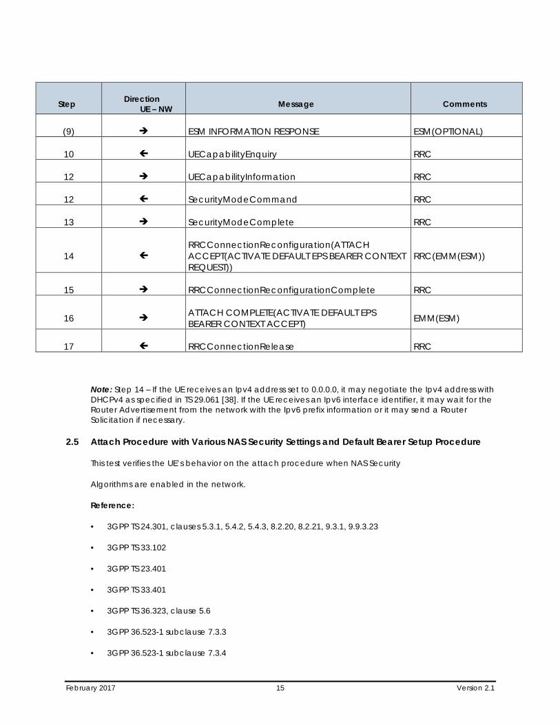
Step Direction UE – NW Message Comments
(9) ESM INFORMATION RESPONSE ESM(OPTIONAL)
10 UECapabilityEnquiry RRC
12 UECapabilityInformation RRC
12 SecurityModeCommand RRC
13 SecurityModeComplete RRC
14 RRCConnectionReconfiguration(ATTACH ACCEPT(ACTIVATE DEFAULT EPS BEARER CONTEXT REQUEST))
RRC(EMM(ESM))
15 RRCConnectionReconfigurationComplete RRC
16 ATTACH COMPLETE(ACTIVATE DEFAULT EPS BEARER CONTEXT ACCEPT) EMM(ESM)
17 RRCConnectionRelease RRC
Note: Step 14 – If the UE receives an Ipv4 address set to 0.0.0.0, it may negotiate the Ipv4 address with DHCPv4 as specified in TS 29.061 [38]. If the UE receives an Ipv6 interface identifier, it may wait for the Router Advertisement from the network with the Ipv6 prefix information or it may send a Router Solicitation if necessary.
2.5 Attach Procedure with Various NAS Security Settings and Default Bearer Setup Procedure
This test verifies the UE’s behavior on the attach procedure when NAS Security
Algorithms are enabled in the network.
Reference:
• 3GPP TS 24.301, clauses 5.3.1, 5.4.2, 5.4.3, 8.2.20, 8.2.21, 9.3.1, 9.9.3.23
• 3GPP TS 33.102
• 3GPP TS 23.401
• 3GPP TS 33.401
• 3GPP TS 36.323, clause 5.6
• 3GPP 36.523-1 subclause 7.3.3
• 3GPP 36.523-1 subclause 7.3.4
February 2017 16 Version 2.1
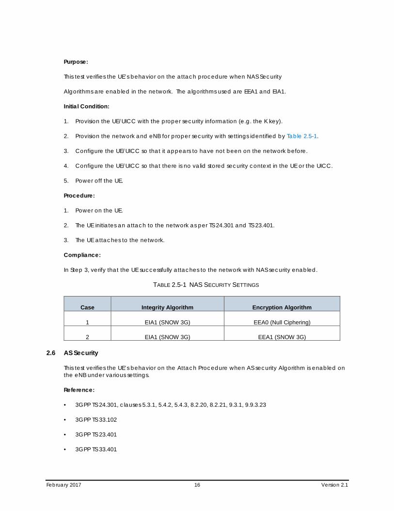
Purpose:
This test verifies the UE’s behavior on the attach procedure when NAS Security
Algorithms are enabled in the network. The algorithms used are EEA1 and EIA1.
Initial Condition:
1. Provision the UE/UICC with the proper security information (e.g. the K key).
2. Provision the network and eNB for proper security with settings identified by Table 2.5-1.
3. Configure the UE/UICC so that it appears to have not been on the network before.
4. Configure the UE/UICC so that there is no valid stored security context in the UE or the UICC.
5. Power off the UE.
Procedure:
1. Power on the UE.
2. The UE initiates an attach to the network as per TS 24.301 and TS 23.401.
3. The UE attaches to the network.
Compliance:
In Step 3, verify that the UE successfully attaches to the network with NAS security enabled.
TABLE 2.5-1 NAS SECURITY SETTINGS
Case Integrity Algorithm Encryption Algorithm
1 EIA1 (SNOW 3G) EEA0 (Null Ciphering)
2 EIA1 (SNOW 3G) EEA1 (SNOW 3G)
2.6 AS Security
This test verifies the UE’s behavior on the Attach Procedure when AS security Algorithm is enabled on the eNB under various settings.
Reference:
• 3GPP TS 24.301, clauses 5.3.1, 5.4.2, 5.4.3, 8.2.20, 8.2.21, 9.3.1, 9.9.3.23
• 3GPP TS 33.102
• 3GPP TS 23.401
• 3GPP TS 33.401
February 2017 17 Version 2.1
• 3GPP TS 36.323, clause 5.6
• 3GPP 36.523-1 subclause 7.3.3
• 3GPP 36.523-1 subclause 7.3.4
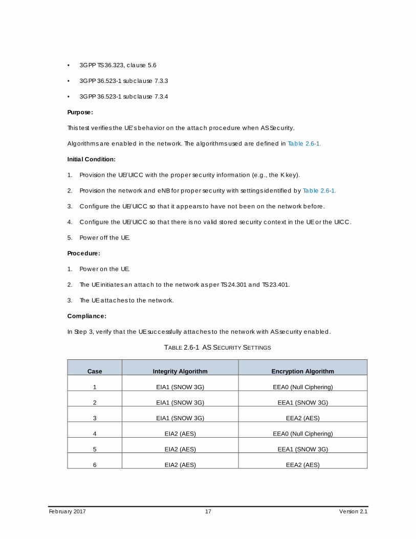
Purpose:
This test verifies the UE’s behavior on the attach procedure when AS Security.
Algorithms are enabled in the network. The algorithms used are defined in Table 2.6-1.
Initial Condition:
1. Provision the UE/UICC with the proper security information (e.g., the K key).
2. Provision the network and eNB for proper security with settings identified by Table 2.6-1.
3. Configure the UE/UICC so that it appears to have not been on the network before.
4. Configure the UE/UICC so that there is no valid stored security context in the UE or the UICC.
5. Power off the UE.
Procedure:
1. Power on the UE.
2. The UE initiates an attach to the network as per TS 24.301 and TS 23.401.
3. The UE attaches to the network.
Compliance:
In Step 3, verify that the UE successfully attaches to the network with AS security enabled.
TABLE 2.6-1 AS SECURITY SETTINGS
Case Integrity Algorithm Encryption Algorithm
1 EIA1 (SNOW 3G) EEA0 (Null Ciphering)
2 EIA1 (SNOW 3G) EEA1 (SNOW 3G)
3 EIA1 (SNOW 3G) EEA2 (AES)
4 EIA2 (AES) EEA0 (Null Ciphering)
5 EIA2 (AES) EEA1 (SNOW 3G)
6 EIA2 (AES) EEA2 (AES)
February 2017 18 Version 2.1
Section 3 Network Access Test Cases
3.1 Attach Reject, Cause #7 "EPS Services Not Allowed"
Check the UE’s behavior on the reject message with cause 7 ‘EPS services not allowed’
Reference:
• TS.11 (30.1.1.2); 3GPP TS 24.301, clause 5.5.1.2.5
Purpose:
To verify that the UE behaves correctly on a reject message ‘‘EPS services not allowed.’
Initial Configuration:
1. UE is powered off.
Procedure:
1. Network does not allow EPS services (e.g. this particular IMSI is not provisioned for EPS services).
2. Power on the UE and attempt Attach procedure.
3. EMM cause at the time of reception of the Attach Reject message is equal to #7 EPS services not allowed.
4. Trigger an Attach procedure (e.g., via AT command). Check whether the UE tries to perform a new registration procedure.
Compliance:
The UE attempts to perform Attach procedure.
1. After Step 2, UE shall not attempt to perform an additional Attach procedure until it is powered off or the SIM card is removed.
2. The UE shall delete any GUTI, last visited registered TAI and KSI. The UE shall consider the USIM as invalid for EPS services until switching off or the UICC containing the USIM is removed.
3. If A/Gb mode or Iu mode is supported by the UE, the UE shall in addition delete P-TMSI, P-TMSI signature, RAI and GPRS ciphering key sequence number.
4. UE shall not perform any additional Attach procedure.
3.2 Attach Reject, Cause #14 "EPS Services Not Allowed in this PLMN" - Multiple PLMN Environment
Check the UE’s behavior on the reject message with cause 14 ‘EPS Services not allowed in this PLMN’.
Reference:
• TS.11 (30.1.1.3.1); 3GPP TS 24.301, clause 5.5.1.2.5
February 2017 19 Version 2.1
Purpose:
To verify that the UE behaves correctly on a reject message ‘EPS Services not allowed in this PLMN’.
Initial Configuration:
1. UE is powered off and in automatic mode.
2. Two PLMNs are available:
3. PLMN1 does not allow EPS Services (e.g. no roaming agreement).
4. PLMN2 does have roaming agreement.
Procedure
1. Power on the UE and attempt Attach procedure on PLMN1.
2. EMM cause at the time of reception of Attach Reject message is equal to #14 “EPS Services not allowed in this PLMN”.
3. UE selects PLMN2 through automatic PLMN selection process.
Compliance:
1. The UE attempts to perform Attach procedure.
2. The UE will not re-attempt to perform an Attach procedure in the PLMN1.
3. UE performs a new ATTACH procedure on selected PLMN – PLMN2.
3.3 Attach Reject, Cause #11 "PLMN Not Allowed"
Check the UE’s behavior on the reject message with cause #11 ‘PLMN not allowed’.
Reference:
• TS.11 (30.1.1.5); 3GPP TS 24.301, clause 5.5.1.2.5
Purpose:
To verify that the UE behaves correctly on a reject message ‘‘PLMN not allowed.’
Initial Configuration:
1. UE is powered off.
2. UE is configured to automatic mode.
3. PLMN1 is E-UTRA radio access technology, PLMN2 can be any RAT that is supported by the UE.
4. UE with USIM that contains EPS LOCI field with PLMN1 as last visited PLMN.
5. UE’s “forbidden PLMN list” is empty.
February 2017 20 Version 2.1
6. Roaming is not allowed with PLMN1.
7. Roaming is allowed with PLMN2.
Procedure:
1. Power on the UE and verify that the UE sends an ATTACH REQUEST to the EPS network PLMN1.
2. The EPS network PLMN1 shall respond to the UE with an ATTACH REJECT with Reject Cause #11 ‘PLMN not allowed’.
3. Check that the UE performs an automatic PLMN selection to another PLMN (e.g., PLMN2) without accessing the “forbidden PLMN”.
4. Perform a manual PLMN selection to PLMN1 and verify that the UE attempts to select the “forbidden PLMN”.
5. Perform a manual PLMN selection to PLMN2 and verify that the UE successfully selects the PLMN.
If the UE is not capable to set-up a mobile terminated service, verify that the UE is registered by setting up a mobile originated connection.
Compliance:
1. The UE performs an Attach procedure on PLMN1.
2. The UE shall set the EPS update status to EU3 ROAMING NOT ALLOWED and shall delete any GUTI, last visited registered TAI and KSI. The UE in S1 mode stores the PLMN identity in the "forbidden PLMN" list and enters state EMM-DEREGISTERED.PLMN-SEARCH.
3. The UE performs an automatic PLMN selection without accessing the “forbidden PLMN”.
4. The UE attempts to perform an ATTACH REQUEST on PLMN1, is rejected with Cause #11 and indicates an error message to the user.
5. The UE performs a successful ATTACH REQUEST on PLMN2.
3.4 Attach Reject, Cause #3 "Illegal UE"
Check the UE’s behavior on the reject message with cause #3 ‘Illegal UE’.
Reference:
• TS.11 (30.1.1.6)
• 3GPP TS 24.301, clause 5.5.1.2.2 and clause 5.5.1.2.5
Purpose:
To verify that the UE behaves correctly on a reject message ‘‘Illegal UE’.
Initial Configuration:
1. At least 2 PLMNs are available and accessible.
February 2017 21 Version 2.1
2. UE is powered off.
3. The UE cannot pass the authentication check, i.e. the RES received from the UE is different from that generated by the network.
Procedure:
1. Power on the UE and verify that the UE sends an ATTACH REQUEST to the EPS network.
2. The EPS network shall respond to the UE with an ATTACH REJECT with Reject Cause #3 ‘Illegal UE’.
3. Wait for 60s in order to check that the UE is not performing an ATTACH REQUEST to any network.
4. Perform a manual network selection.
5. Power Cycle the UE and verify the UE sends an ATTACH REQUEST to the EPS network.
Compliance:
1. The UE performs an Attach procedure.
2. The UE shall delete the list of equivalent PLMNs and enter state EMM-DEREGISTERED.
3. The UE does not send any ATTACH REQUEST message.
4. The UE does not send any ATTACH REQUEST message.
5. The UE performs an Attach attempt procedure with IMSI1.
3.5 Attach Reject – Cause Code #15 (No Suitable Cells in Tracking Area)
This test verifies the UE’s behavior when the network rejects the attach with the Cause Code #15, “No Suitable Cells in Tracking Area.”
Reference:
• 3GPP TS 24.301, clauses 5.5.1.2.2, 5.5.1.2.5 and 5.3.2
Purpose:
This test verifies the UE’s behavior when the network rejects the attach with the Cause Code #15, “No Suitable Cells in Tracking Area.”
Initial Condition:
1. Configure the network so that a least 2 PLMN’s are available and accessible.
2. Configure the UICC so that the UE selects PLMN1 and never selects PLMN2.
3. Configure the PLMN’s and the UICC so that the UE is in a tracking area that is not allowed, i.e., the HPLMN determines that the UE, by subscription, is not allowed to operate in that PLMN.
4. The UE is powered off.

February 2017 22 Version 2.1
Procedure:
1. Power on the UE.
2. When the UE attempts to attach to the EPS network, the EPS network shall respond to the UE with an ATTACH REJECT with Reject Cause code #15 “No Suitable Cells in Tracking Area.”
3. Wait for 60 seconds in order to check that the UE is not performing an ATTACH REQUEST to any network.
4. Perform a manual network selection to the PLMN selected in Step 1.
5. Power Cycle the UE.
6. The UE attempts to attach to the network via the PLMN selected in Step 1.
Compliance:
1. In Step 2, verify that the UE performs an Attach procedure.
2. In Step 3, verify that the UE does not send any ATTACH REQUEST messages.
3. In Step 6, verify that the UE attempts to attach to the network.
3.6 Attach Reject – Cause Code #6 (Illegal ME)
This test verifies the UE’s behavior when the network rejects the initial attach with the Cause Code #6, “Illegal ME.”
Reference:
• 3GPP TS 24.301, clause 5.5.1.2.2 and clause 5.5.1.2.5
• 3GPP TS 22.016, clause 5
Purpose:
This test verifies the UE’s behavior when the network rejects the initial attach with the Cause Code #6, “Illegal ME.”
Initial Condition:
1. Configure the network so that a least 2 PLMNs are available and accessible.
2. Configure the UICC so that the UE selects either of the PLMN’s.
3. Configure the Network Equipment Identity Register (EIR) so that the UE/ME is in the black list (black listed), or not in the white list (unknown).
4. The UE is powered off.
Procedure:
1. Power on the UE.
February 2017 23 Version 2.1
2. When the UE attempts to attach to the EPS network, the EPS network shall respond to the UE with an ATTACH REJECT with Reject Cause code #6 ‘Illegal ME’.
3. Wait for 60 seconds in order to check that the UE is not performing an ATTACH REQUEST to any network.
4. Perform a manual network selection to the PLMN selected in Step 1.
5. Power Cycle the UE.
6. The UE attempts to attach to the network via the PLMN selected in Step 1.
Compliance:
1. In Step 2, verify that the UE performs an Attach procedure.
2. In Step 3, verify that the UE does not send any ATTACH REQUEST messages.
3. In Step 6, verify that the UE attempts to attach to the network.
3.7 Attach Reject – Cause Code # 12 (Tracking Area Not Allowed)
This test verifies the UE’s behavior when the network rejects the attach with the Cause Code #12, “Tracking Area Not Allowed.”
Reference:
• 3GPP TS 24.301, clauses 5.5.1.2.2, 5.5.1.2.5 and 5.3.2
Purpose:
This test verifies the UE’s behavior when the network rejects the attach with the Cause Code #12, “Tracking Area Not Allowed.”
Initial Condition:
1. Configure the network so that a least 2 PLMN’s are available and accessible.
2. Configure the UICC so that the UE selects either of the PLMN’s.
3. Configure the PLMN’s and the UICC so that the UE is in a tracking area that is not allowed, i.e. the HPLMN determines that the UE, by subscription, is not allowed to operate in that PLMN.
4. The UE is powered off.
Procedure:
1. Power on the UE.
2. When the UE attempts to attach to the EPS network, the EPS network shall respond to the UE with an ATTACH REJECT with Reject Cause code #12 “Tracking Area Not Allowed.”
3. Wait for 60 seconds in order to check that the UE is not performing an ATTACH REQUEST to any network.
February 2017 24 Version 2.1
4. Perform a manual network selection to the PLMN selected in Step 1.
5. Power Cycle the UE.
6. The UE attempts to attach to the network via the PLMN selected in Step 1.
Compliance:
1. In Step 2, verify that the UE performs an Attach procedure.
2. In Step 3, verify that the UE does not send any ATTACH REQUEST messages.
3. In Step 6, verify that the UE attempts to attach to the network.
3.8 Tracking Area Update Reject, Cause Code #3 (Illegal UE)
This test case verifies that the UE behaves correctly in response to a tracking area update reject message with cause code #3 “Illegal UE.”
Reference:
• 3GPP TS 24.301, clause 5.5.3.2.4 and clause 5.5.3.2.5
Purpose:
This test case verifies that the UE behaves correctly in response to a tracking area update reject message with cause code #3 “Illegal UE.”
Initial Condition:
1. Configure the network to show at least 2 Tracking Areas.
2. Configure the network so that the UE can pass the authentication check for Tracking Area #1 but not for Tracking Area #2.
3. Ensure that the UE will attach to the network in Tracking Area #1.
4. UE is powered off.
Procedure:
1. Power on the UE.
2. Wait until the UE attaches to the network in Tracking Area #1.
3. Ensure that the UE is in RRC_IDLE.
4. Force the UE to reselect from Tracking Area #1 to Tracking Area #2.
5. The EPS network shall respond to the UE from Tracking Area #2 with a TRACKING AREA UPDATE REJECT with Reject Cause code #3 ‘Illegal UE’.
6. Wait for 60s.
February 2017 25 Version 2.1
7. Power off the UE.
8. Configure the network so that the UE will attach to the network in Tracking Area #1.
9. Power on the UE.
10. The UE attaches to the network Tracking Area #1.
Compliance:
1. In Step 2, verify that the UE attaches to the network in Tracking Area #1.
2. In Step 6, verify that the UE does not send any ATTACH REQUEST messages after the reject from Tracking Area #2.
3. In Step 10, verify that the UE attaches to the network in Tracking Area #1 after powering up.
3.9 Detach - With Power-off
The UE shall successfully perform a UE initiated detach procedure.
Reference:
• TS.11 (30.1.1.8.1); 3GPP TS 24.301, section 5.5.2.2
Purpose:
To verify that the UE successfully performs a UE initiated detach procedure.
Initial Configuration:
1. UE is powered off.
Procedure
1. Power off the UE.
2. If possible use a diagnostic tool to verify that the UE sends a DETACH REQUEST message with Switch off in the Detach type set to “switch off" and Type of detach in the Detach type set to “EPS detach”.
3. Perform a mobile terminated service connection (e.g. voice call or ping) from other device.
4. Verify that the mobile terminated service connection is not reachable.
Compliance:
1. The UE successfully performs the Detach procedure.
February 2017 26 Version 2.1
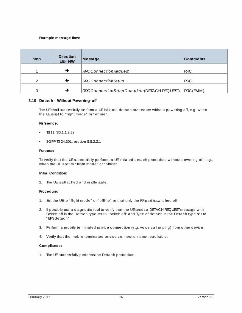
Example message flow:
Step Direction UE - NW Message Comments
1 RRCConnectionRequest RRC
2 RRCConnectionSetup RRC
3 RRCConnectionSetupComplete(DETACH REQUEST) RRC(EMM)
3.10 Detach - Without Powering-off
The UE shall successfully perform a UE initiated detach procedure without powering off, e.g. when the UE is set to “flight mode” or “offline”.
Reference:
• TS.11 (30.1.1.8.2)
• 3GPP TS 24.301, section 5.5.2.2.1
Purpose:
To verify that the UE successfully performs a UE initiated detach procedure without powering off, e.g., when the UE is set to “flight mode” or “offline”.
Initial Condition:
2. The UE is attached and in idle state.
Procedure:
1. Set the UE to “flight mode” or “offline” so that only the RF part is switched off.
2. If possible use a diagnostic tool to verify that the UE sends a DETACH REQUEST message with Switch off in the Detach type set to “switch off" and Type of detach in the Detach type set to “EPS detach”.
3. Perform a mobile terminated service connection (e.g. voice call or ping) from other device.
4. Verify that the mobile terminated service connection is not reachable.
Compliance:
1. The UE successfully performs the Detach procedure.
February 2017 27 Version 2.1
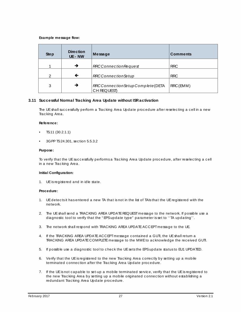
Example message flow:
Step Direction UE - NW Message Comments
1 RRCConnectionRequest RRC
2 RRCConnectionSetup RRC
3 RRCConnectionSetupComplete(DETACH REQUEST)
RRC(EMM)
3.11 Successful Normal Tracking Area Update without ISR activation
The UE shall successfully perform a Tracking Area Update procedure after reselecting a cell in a new Tracking Area.
Reference:
• TS.11 (30.2.1.1)
• 3GPP TS 24.301, section 5.5.3.2
Purpose:
To verify that the UE successfully performs a Tracking Area Update procedure, after reselecting a cell in a new Tracking Area.
Initial Configuration:
1. UE is registered and in idle state.
Procedure:
1. UE detects it has entered a new TA that is not in the list of TAIs that the UE registered with the network.
2. The UE shall send a TRACKING AREA UPDATE REQUEST message to the network. If possible use a diagnostic tool to verify that the “EPS update type” parameter is set to ‘‘TA updating’’.
3. The network shall respond with TRACKING AREA UPDATE ACCEPT message to the UE.
4. If the TRACKING AREA UPDATE ACCEPT message contained a GUTI, the UE shall return a TRACKING AREA UPDATE COMPLETE message to the MME to acknowledge the received GUTI.
5. If possible use a diagnostic tool to check the UE sets the EPS update status to EU1 UPDATED.
6. Verify that the UE is registered to the new Tracking Area correctly by setting up a mobile terminated connection after the Tracking Area Update procedure.
7. If the UE is not capable to set-up a mobile terminated service, verify that the UE is registered to the new Tracking Area by setting up a mobile originated connection without establishing a redundant Tracking Area Update procedure.
February 2017 28 Version 2.1
Compliance:
1. The UE performs a Tracking Area Update procedure.
2. The UE establishes a mobile terminated service connection or a mobile originated service connection.
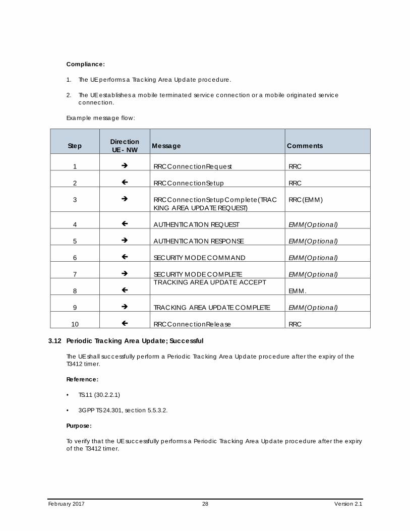
Example message flow:
Step Direction UE - NW Message Comments
1 RRCConnectionRequest RRC
2 RRCConnectionSetup RRC
3 RRCConnectionSetupComplete(TRACKING AREA UPDATE REQUEST)
RRC(EMM)
4 AUTHENTICATION REQUEST EMM(Optional)
5 AUTHENTICATION RESPONSE EMM(Optional)
6 SECURITY MODE COMMAND EMM(Optional)
7 SECURITY MODE COMPLETE EMM(Optional)
8 TRACKING AREA UPDATE ACCEPT
EMM.
9 TRACKING AREA UPDATE COMPLETE EMM(Optional)
10 RRCConnectionRelease RRC
3.12 Periodic Tracking Area Update; Successful
The UE shall successfully perform a Periodic Tracking Area Update procedure after the expiry of the T3412 timer.
Reference:
• TS.11 (30.2.2.1)
• 3GPP TS 24.301, section 5.5.3.2.
Purpose:
To verify that the UE successfully performs a Periodic Tracking Area Update procedure after the expiry of the T3412 timer.
February 2017 29 Version 2.1
Initial Condition:
1. The UE is attached and in idle state, T3412 is reset.
Procedure:
1. Wait for the T3412 timer to expire, and if possible use a diagnostic tool to verify that the UE sends a TRACKING AREA UPDATE REQUEST message with EPS update type set to "periodic updating".
2. Verify that the UE is registered to the Tracking Area correctly by setting up a mobile terminated connection after the Tracking Area Update procedure.
3. If the UE is not capable to set-up a mobile terminated service, verify that the UE is registered to the Tracking Area by setting up a mobile originated connection without establishing a redundant Tracking Area Update procedure.
Compliance:
1. The UE performs a Periodic Tracking Area Update procedure.
2. The UE establishes a mobile terminated service connection.
3. The UE establishes a mobile originated service connection.
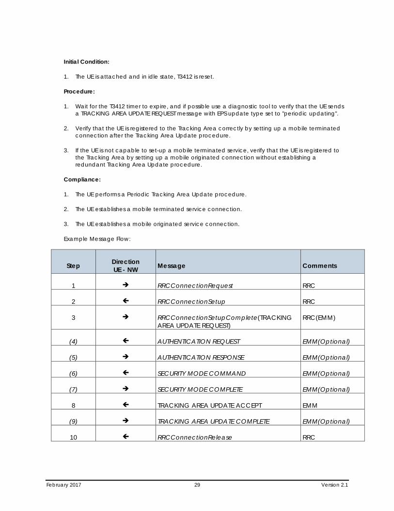
Example Message Flow:
Step Direction UE - NW Message Comments
1 RRCConnectionRequest RRC
2 RRCConnectionSetup RRC
3 RRCConnectionSetupComplete(TRACKING AREA UPDATE REQUEST)
RRC(EMM)
(4) AUTHENTICATION REQUEST EMM(Optional)
(5) AUTHENTICATION RESPONSE EMM(Optional)
(6) SECURITY MODE COMMAND EMM(Optional)
(7) SECURITY MODE COMPLETE EMM(Optional)
8 TRACKING AREA UPDATE ACCEPT EMM
(9) TRACKING AREA UPDATE COMPLETE EMM(Optional)
10 RRCConnectionRelease RRC
February 2017 30 Version 2.1
3.13 Network Selection - Manual Mode – Network on Forbidden List
If in manual network selection mode, the UE shall list all available PLMNs. This behavior is independent from the content of the preferred PLMN list.
Reference:
• TS.11 (30.3.2.1)
• 3GPP TS 22.011, subclause 3.2.2.2
Purpose:
To ensure that the correct list of PLMNs is displayed for the purposes of manual PLMN selection.
Initial Condition:
1. UE switched on, in automatic selection mode in an area with coverage from GSM, UMTS and E-UTRAN networks.
Procedure:
1. The number of the entries in preferred PLMN list is less than or equal to 32 entries.
2. Select the manual network selection mode on the UE and ensure that the list of all available PLMNs is displayed, and that the displayed networks can be selected, even if on the forbidden list.
3. Check that the preferred PLMN list is not changed after the manual network selection.
Compliance:
The UE shall display all available PLMNs and it shall perform manual network selection on the chosen network. The preferred PLMN list is not changed after the manual network selection.
The UE shall display all available GSM/UMTS and E-UTRAN networks.
3.14 Network Selection - Manual Mode – Empty Preferred PLMN List
If in manual network selection mode, the UE shall list all available PLMNs. This behavior is independent from the content of the preferred PLMN list.
Reference:
• TS.11 (30.3.2.1)
• 3GPP TS 22.011, subclause 3.2.2.2
Purpose:
To ensure that the correct list of PLMNs is displayed for the purposes of manual PLMN selection.
February 2017 31 Version 2.1
Initial Condition:
1. UE switched on, in automatic selection mode in an area with coverage from GSM, UMTS and E-UTRAN networks.
Procedure:
1. The number of the entries in preferred PLMN list is empty.
2. Select the manual network selection mode on the UE and ensure that the list of all available PLMNs is displayed, and that the displayed networks can be selected, even with an empty list in the preferred PLMN list.
3. Check that the preferred PLMN list is not changed after the manual network selection.
Compliance:
1. The UE shall display all available PLMNs and it shall perform manual network selection on the chosen network. The preferred PLMN list is not changed after the manual network selection.
2. The UE shall display all available GSM/UMTS and E-UTRAN networks.
3.15 Network Selection -– Manual Mode – More than 32 Entries on Preferred PLMN List
If in manual network selection mode, the UE shall list all available PLMNs. This behavior is independent from the content of the preferred PLMN list.
Reference:
• TS.11 (30.3.2.1)
• 3GPP TS 22.011, subclause 3.2.2.2
Purpose:
To ensure that the correct list of PLMNs is displayed for the purposes of manual PLMN selection.
Initial Condition:
1. UE switched on, in automatic selection mode in an area with coverage from GSM, UMTS and E-UTRAN networks.
Procedure:
1. The number of the entries in preferred PLMN list is more than or equal to 32 entries.
2. Select the manual network selection mode on the UE and ensure that the list of all available PLMNs is displayed, and that the displayed networks can be selected, even with more than 32 entries in the preferred PLMN list.
3. Check that the preferred PLMN list is not changed after the manual network selection.
February 2017 32 Version 2.1
Compliance:
1. The UE shall display all available PLMNs and it shall perform manual network selection on the chosen network. The preferred PLMN list is not changed after the manual network selection.
2. The UE shall display all available GSM/UMTS and E-UTRAN networks.
3.16 Network Selection – Selection Mode Following Switch off – Manual Network Selection
The UE shall be retaining its configuration of automatic and manual network selection modes when switched off.
Reference:
• TS.11 (30.3.2.3)
• 3GPP TS 22.011, subclause 3.2.2.2
Purpose:
To ensure that the UE retains its configuration of manual selection mode when switched off.
Initial Condition:
1. UE in idle mode, with automatic network selection mode configured.
Procedure:
1. Change to manual network selection. Turn the UE off and on again. Check that the manual network selection mode is in use.
Compliance:
1. The UE has the same selection mode when switched on that it had when switched off.
3.17 Network Selection – Selection Mode Following Switch off – Automatic Network Selection
The UE shall be retaining its configuration of automatic and manual network selection modes when switched off.
Reference:
• TS.11 (30.3.2.3)
• 3GPP TS 22.011, subclause 3.2.2.2
Purpose:
To ensure that the UE retains its configuration of automatic selection mode when switched off.
Initial Condition:
1. UE in idle mode, with manual network selection mode configured.
February 2017 33 Version 2.1
Procedure:
1. Change to automatic network selection. Turn the UE off and on again. Check that the automatic network selection mode is in use.
Compliance:
1. The UE has the same selection mode when switched on that it had when switched off.
February 2017 34 Version 2.1
Section 4 Intra-LTE Mobility (Intra-Freq)
All Handover and Reselection tests should be done back and forth between two cells, i.e., cell-A to cell-B then back to Cell-A.
4.1 Idle Mode E-UTRA Intra-Frequency Reselection
The UE should perform a reselection without losing service.
Reference:
• TS.11 (31.1.1.1)
• 3GPP TS36.304
Purpose:
To ensure that the UE performs a reselection correctly without losing service.
Initial Condition:
1. Two cells shall be active in eNB. These cells shall belong to the same PLMN.
2. The signal of one of the cells is to be attenuated more than the other.
The UE is in state RRC_IDLE and camps on the stronger cell.
Procedure:
1. Adjust attenuation to make the other cell signal stronger . Ensure that the UE performs reselections as expected. During the reselections it is imperative the UE remains in service at all times, and that its PDN Connectivity context remains viable before and after the reselections. Where possible, this procedure should be carried out as follows:
a. Between cells sharing a Tracking Area.
b. Between cells utilizing the same E-UTRA ARFCN.
c. In areas of poor signal strength.
Compliance:
1. The UE should perform reselections correctly, without losing service, and its PDN connectivity should remain viable before and after the reselections.
2. The UE should successfully establish a mobile terminated service connection after the reselections.
3. If the UE is not capable to setup a mobile terminated service, verify that the UE can setup a mobile originated connection (e.g., Service Request procedure).
February 2017 35 Version 2.1
4.2 E-UTRA Handover, Default Ipv4 Bearer – Intra eNodeB Handover
The UE should perform handovers as requested by the network, and behave as expected from the user perspective without losing services.
Reference:
• TS.11 (31.2.1.1)
• 3GPP TS36.300
• 3GPP TS 36.331
• 3GPP TS 36.423
• 3GPP TS 36.413
• 3GPP 23.401
Purpose:
To ensure that the UE performs handovers correctly without losing services.
Initial Condition:
1. There must be a sufficient number of E-UTRA cells available on the same PLMN.
Procedure:
1. Move between the different cells. Ensure that the UE performs reselections/handovers as expected. During the test it is imperative the UE remains in service at all times, that the packet bearer in question is maintained throughout the test and that the FTP download is resumed correctly.
Scenario A:
Only default Ipv4 bearer is required for the scenario A and only a basic test case (e.g., FTP Download).
Compliance:
1. The UE should perform handovers correctly, without losing service, and its PDN connectivity should remain viable before and after the handovers.
2. The UE should successfully resume the FTP downloads after the handovers.
4.3 E-UTRA Handover, Default Ipv4 Bearer – X2 Based
The UE should perform handovers as requested by the network, and behave as expected from the user perspective without losing services.
Reference:
• TS.11 (31.2.1.1)
February 2017 36 Version 2.1
• 3GPP TS36.300
• 3GPP TS 36.331
• 3GPP TS 36.423
• 3GPP TS 36.413
• 3GPP TS 24.301
Purpose:
To ensure that the UE performs handovers correctly without losing services.
Initial Condition:
1. There must be a sufficient number of E-UTRA cells available on the same PLMN.
This scenario is designed to test inter eNB Handovers – X2 Based
Procedure:
1. Move between the different cells of a test. Ensure that the UE performs reselections/handovers as expected. During the test it is imperative the UE remains in service at all times, that the packet bearer in question is maintained throughout the test and that the FTP download is resumed correctly.
Scenario A:
Only default Ipv4 bearer is required for the scenario A and only a basic test case (e.g. FTP Download).
Compliance:
1. The UE should perform handovers correctly, without losing service, and its PDN connectivity should remain viable before and after the handovers.
2. The UE should successfully resume the FTP downloads after the handovers.
4.4 E-UTRA Handover, Default Ipv4 Bearer – S1 Based
The UE should perform handovers as requested by the network, and behave as expected from the user perspective without losing services.
Reference:
• TS.11 (31.2.1.1)
• 3GPP TS36.300
• 3GPP TS 36.331
• 3GPP TS 36.423
February 2017 37 Version 2.1
• 3GPP TS 36.413
• 3GPP TS 24.301
Purpose:
1. To ensure that the UE performs handovers correctly without losing services.
Initial Condition:
1. There must be a sufficient number of E-UTRA cells available on the same PLMN. Required Ipv4 packet bearers to be tested should be active, and available in all parts of the test.
This scenario is designed to test inter eNB Handovers – S1 Based (no X2 interface between eNB)
Procedure:
1. Move between the different cells of a test. Ensure that the UE performs reselections/handovers as expected. During the test it is imperative the UE remains in service at all times, that the packet bearer in question is maintained throughout the test and that the FTP download is resumed correctly.
Scenario A:
Only default Ipv4 bearer is required for the scenario A and only a basic test case (e.g. FTP Download).
Compliance:
1. The UE should perform handovers correctly, without losing service, and its PDN connectivity should remain viable before and after the handovers.
2. The UE should successfully resume the FTP downloads after the handovers.
4.5 E-UTRA Handover, Default Ipv4 Bearer – Inter-MME
The UE should perform handovers as requested by the network, and behave as expected from the user perspective without losing services.
Reference:
• TS.11 (31.2.1.1)
• 3GPP TS36.300
• 3GPP TS 36.331
• 3GPP TS 36.423
• 3GPP TS 36.413
• 3GPP TS 24.301
February 2017 38 Version 2.1
Purpose:
To ensure that the UE performs handovers correctly without losing services.
Initial Condition:
1. There must be a sufficient number of E-UTRA cells available on the same PLMN. Required Ipv4 packet bearers to be tested should be active, and available in all parts of the test.
This scenario is designed to test inter MME Handovers
Procedure:
1. Move between the different cells of a test. Ensure that the UE performs reselections/handovers as expected. During the test it is imperative the UE remains in service at all times, that the packet bearer in question is maintained throughout the test and that the FTP download is resumed correctly.
Scenario A:
Only default Ipv4 bearer is required for the scenario A and only a basic test case (e.g. FTP Download).
Compliance:
1. The UE should perform handovers correctly, without losing service, and its PDN connectivity should remain viable before and after the handovers.
2. The UE should successfully resume the FTP downloads after the handovers.
4.6 E-UTRA Handover, Default Ipv6 Bearer – Intra eNodeB Handover
The UE should perform handovers as requested by the network, and behave as expected from the user perspective without losing services.
Reference:
• TS.11 (31.2.1.1)
• 3GPP TS36.300
• 3GPP TS 36.331
• 3GPP TS 36.423
• 3GPP TS 36.413
• 3GPP 23.401
Purpose:
To ensure that the UE performs handovers correctly without losing services.
February 2017 39 Version 2.1
Initial Condition:
1. There must be a sufficient number of E-UTRA cells available on the same PLMN. Required Ipv6 packet bearers to be tested should be active, and available in all parts of the test route.
Procedure:
1. Move between the different cells of a test. Ensure that the UE performs reselections/handovers as expected. During the test it is imperative the UE remains in service at all times, that the packet bearer in question is maintained throughout the test and that the FTP download is resumed correctly.
Scenario A:
Only default Ipv6 bearer is required for the scenario A and only a basic test case (e.g. FTP Download).
Compliance:
1. The UE should perform handovers correctly, without losing service, and its PDN connectivity should remain viable before and after the handovers.
2. The UE should successfully resume the FTP downloads after the handovers.
4.7 E-UTRA Handover, Default Ipv6 Bearer – X2 Based
The UE should perform handovers as requested by the network, and behave as expected from the user perspective without losing services.
Reference:
• TS.11 (31.2.1.1)
• 3GPP TS36.300
• 3GPP TS 36.331
• 3GPP TS 36.423
• 3GPP TS 36.413
• 3GPP TS 24.301
Purpose:
To ensure that the UE performs handovers correctly without losing services.
Initial Condition:
1. There must be a sufficient number of E-UTRA cells available on the same PLMN. Required Ipv6 packet bearers to be tested should be active, and available in all parts of the test.
This scenario is designed to test inter eNB Handovers – X2 Based
February 2017 40 Version 2.1
Procedure:
1. Move between the different cells of a test. Ensure that the UE performs reselections/handovers as expected. During the test it is imperative the UE remains in service at all times, that the packet bearer in question is maintained throughout the test and that the FTP download is resumed correctly.
Scenario A:
Only default Ipv6 bearer is required for the scenario A and only a basic test case (e.g., FTP Download).
Compliance:
1. The UE should perform handovers correctly, without losing service, and its PDN connectivity should remain viable before and after the handovers.
2. The UE should successfully resume the FTP downloads after the handovers.
4.8 E-UTRA Handover, Default Ipv6 Bearer – S1 Based
The UE should perform handovers as requested by the network, and behave as expected from the user perspective without losing services.
Reference:
• TS.11 (31.2.1.1)
• 3GPP TS36.300
• 3GPP TS 36.331
• 3GPP TS 36.423
• 3GPP TS 36.41
• 3GPP TS 24.301
Purpose:
1. To ensure that the UE performs handovers correctly without losing services.
Initial Condition:
1. There must be a sufficient number of E-UTRA cells available on the same PLMN. Required Ipv6 packet bearers to be tested should be active, and available in all parts of the test.
This scenario is designed to test inter eNB Handovers – S1 Based (no X2 interface between eNB)
Procedure:
1. Move between the different cells of a test. Ensure that the UE performs reselections/handovers as expected. During the test it is imperative the UE remains in service at all times, that the packet bearer in question is maintained throughout the test and that the FTP download is resumed correctly.
February 2017 41 Version 2.1
Scenario A:
Only default Ipv6 bearer is required for the scenario A and only a basic test case (e.g., FTP Download).
Compliance:
1. The UE should perform handovers correctly, without losing service, and its PDN connectivity should remain viable before and after the handovers.
2. The UE should successfully resume the FTP downloads after the handovers.
4.9 E-UTRA Handover, Default Ipv6 Bearer – Inter-MME
The UE should perform handovers as requested by the network, and behave as expected from the user perspective without losing services.
Reference:
• TS.11 (31.2.1.1)
• 3GPP TS36.300
• 3GPP TS 36.331
• 3GPP TS 36.423
• 3GPP TS 36.413
• 3GPP TS 24.301
Purpose:
To ensure that the UE performs handovers correctly without losing services.
Initial Condition:
1. There must be a sufficient number of E-UTRA cells available on the same PLMN. Required Ipv6 packet bearers to be tested should be active, and available in all parts of the test.
This scenario is designed to test inter MME Handovers.
Procedure:
1. Move between the different cells of a test. Ensure that the UE performs reselections/handovers as expected. During the test it is imperative the UE remains in service at all times, that the packet bearer in question is maintained throughout the test and that the FTP download is resumed correctly.
Scenario A:
Only default Ipv6 bearer is required for the scenario A and only a basic test case (e.g. FTP Download).
February 2017 42 Version 2.1
Compliance:
1. The UE should perform handovers correctly, without losing service, and its PDN connectivity should remain viable before and after the handovers.
2. The UE should successfully resume the FTP downloads after the handovers.
4.10 E-UTRA Handover, Dual Ipv6/Ipv4 Bearer – X2 Based
The UE should perform handovers as requested by the network, and behave as expected from the user perspective without losing services.
Reference:
• TS.11 (31.2.1.1)
• 3GPP TS36.300
• 3GPP TS 36.331
• 3GPP TS 36.423
• 3GPP TS 36.413
• 3GPP TS 24.301
Purpose:
To ensure that the UE performs handovers correctly without losing services.
Initial Condition:
1. There must be a sufficient number of E-UTRA cells available on the same PLMN. Required Ipv6 and Ipv4 packet bearers to be tested should be active, and available in all parts of the test.
This scenario is designed to test inter eNB Handovers – X2 Based
Procedure:
1. Move between the different cells of a test. Ensure that the UE performs reselections/handovers as expected. During the test it is imperative the UE remains in service at all times, that the packet bearer in question is maintained throughout the test and that the FTP download is resumed correctly.
Scenario B:
Both Ipv6 and Ipv4 bearers are required for the scenario B and a dual bearer test case (e.g. FTP Download on Ipv6 bearer and FTP Upload on Ipv4 bearer).
Compliance:
1. The UE should perform handovers correctly, without losing service, and its PDN connectivity should remain viable before and after the handovers.
February 2017 43 Version 2.1
2. The UE should successfully resume the FTP downloads and uploads after the handovers.
4.11 E-UTRA Handover, Dual Ipv6/Ipv4 Bearer – S1 Based
The UE should perform handovers as requested by the network, and behave as expected from the user perspective without losing services.
Reference:
• TS.11 (31.2.1.1)
• 3GPP TS36.300
• 3GPP TS 36.331
• 3GPP TS 36.423
• 3GPP TS 36.413
• 3GPP TS 24.301
Purpose:
1. To ensure that the UE performs handovers correctly without losing services.
Initial Condition:
1. There must be a sufficient number of E-UTRA cells available on the same PLMN. Required Ipv6 and Ipv4 packet bearers to be tested should be active, and available in all parts of the test.
This scenario is designed to test inter eNB Handovers – S1 Based (no X2 interface between eNB)
Procedure:
1. Move between the coverage areas of the different cells of a test route. Ensure that the UE performs reselections/handovers as expected. During the test drive it is imperative the UE remains in service at all times, that the packet bearer in question is maintained throughout the test route and that the FTP download is resumed correctly.
Scenario B:
Both Ipv6 and Ipv4 bearers are required for the scenario B and a dual bearer test case (e.g. FTP Download on Ipv6 bearer and FTP Upload on Ipv4 bearer).
Compliance:
1. The UE should perform handovers correctly, without losing service, and its PDN connectivity should remain viable before and after the handovers.
2. The UE should successfully resume the FTP downloads and uploads after the handovers.
February 2017 44 Version 2.1
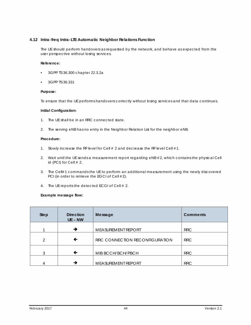
4.12 Intra-freq Intra-LTE Automatic Neighbor Relations Function
The UE should perform handovers as requested by the network, and behave as expected from the user perspective without losing services.
Reference:
• 3GPP TS 36.300 chapter 22.3.2a
• 3GPP TS 36.331
Purpose:
To ensure that the UE performs handovers correctly without losing services and that data continues.
Initial Configuration:
1. The UE shall be in an RRC connected state.
2. The serving eNB has no entry in the Neighbor Relation List for the neighbor eNB.
Procedure:
1. Slowly increase the RF level for Cell # 2 and decrease the RF level Cell #1.
2. Wait until the UE sends a measurement report regarding eNB #2, which contains the physical Cell id (PCI) for Cell # 2.
3. The Cell#1 commands the UE to perform an additional measurement using the newly discovered PCI (in order to retrieve the EGCI of Cell #2).
4. The UE reports the detected ECGI of Cell # 2.
Example message flow:
Step Direction UE – NW
Message Comments
1 MEASUREMENT REPORT RRC
2 RRC CONNECTION RECONFIGURATION RRC
3 MIB BCCH/BCH/PBCH RRC
4 MEASUREMENT REPORT RRC
February 2017 45 Version 2.1
Section 5 Intra-LTE Mobility (Inter-Freq)
All Handover and Reselection tests should be done back and forth between two cells, i-e Cell-A to Cell-B then back to Cell-A
Reselection/Handover between FDD and TDD is part of the intra-LTE and inter-Freq reselection/handover scenarios when the cells are involved in different duplex modes (FDD or TDD). Therefore, if the UE supports dual-mode (FDD and TDD), then dual-mode scenarios shall be included in scenarios 5.3, 5.4, 5.7 and 5.8.
5.1 Idle Mode E-UTRA Inter-Frequency Intra-Band (Same BW) Reselection
The UE should perform a reselection without losing service.
Reference:
• TS.11 (31.1.1.2)
• 3GPP TS36.304
Purpose:
To ensure that the UE performs a reselection correctly without losing service.
Initial Condition:
1. There must be a sufficient number of E-UTRAN cells available on the same PLMN but on different frequencies, and the UE should be in idle mode (ECM-IDLE and EMM-REGISTERED).
Procedure:
1. Move between the different cells on a test. The test should contain the scenarios listed below. Ensure that the UE performs reselections as expected. During the reselections it is imperative the UE remains in service at all times, and that its PDN Connectivity context remains viable before and after the reselections. Where possible, this procedure should be carried out as follows:
a. Between cells sharing a Tracking Area.
b. Between cells utilizing different E-UTRA ARFCNs belonging to a common E-UTRA frequency band and common E-UTRA frequency bandwidth.
c. In areas of poor signal strength.
Compliance:
1. The UE should perform reselections correctly, without losing service, and its PDN connectivity should remain viable before and after the reselections.
2. The UE should successfully establish a mobile terminated service connection after the reselections.
3. If the UE is not capable to setup a mobile terminated service, verify that the UE can setup a mobile originated connection (e.g. Service Request procedure).
February 2017 46 Version 2.1
5.2 Idle Mode E-UTRA Inter-Frequency Intra-Band Inter-BW Reselection
The UE should perform a reselection without losing service.
Reference:
• 3GPP TS36.304
Purpose:
To ensure that the UE performs a reselection correctly without losing service.
Initial Condition:
1. There must be a sufficient number of E-UTRAN cells available on the same PLMN but on different frequencies, and the UE should be in idle mode (ECM-IDLE and EMM-REGISTERED).
Procedure:
1. Move between the different cells on a test. The test should contain the scenarios listed below. Ensure that the UE performs reselections as expected. During the reselections it is imperative the UE remains in service at all times, and that its PDN Connectivity context remains viable before and after the reselections. Where possible, this procedure should be carried out as follows:
a. Between cells sharing a Tracking Area.
b. Between cells utilizing different E-UTRA ARFCNs belonging to a common E-UTRA frequency band with different E-UTRA frequency bandwidths.
c. In areas of poor signal strength.
Compliance:
1. The UE should perform reselections correctly, without losing service, and its PDN connectivity should remain viable before and after the reselections.
2. The UE should successfully establish a mobile terminated service connection after the reselections.
3. If the UE is not capable to setup a mobile terminated service, verify that the UE can setup a mobile originated connection (e.g. Service Request procedure).
5.3 Idle Mode E-UTRA Inter-Frequency Inter-Band (Same BW) Reselection
The UE should perform a reselection without losing service.
In case of dual-mode UE, inter-band reselection may include a change of mode (TDD↔FDD).
Reference:
• 3GPP TS36.304
February 2017 47 Version 2.1
Purpose:
To ensure that the UE performs a reselection correctly without losing service.
Initial Condition:
1. There must be a sufficient number of E-UTRAN cells available on the same PLMN but on different frequencies, and the UE should be in idle mode (ECM-IDLE and EMM-REGISTERED).
Procedure:
1. Move between the different cells on a test. The test should contain the scenarios listed below. Ensure that the UE performs reselections as expected. During the reselections it is imperative the UE remains in service at all times, and that its PDN Connectivity context remains viable before and after the reselections. Where possible, this procedure should be carried out as follows:
a. Between cells sharing a Tracking Area.
b. Between cells utilizing different E-UTRA ARFCNs belonging to different E-UTRA frequency bands and common E-UTRA frequency bandwidth.
c. In areas of poor signal strength.
Compliance:
1. The UE should perform reselections correctly, without losing service, and its PDN connectivity should remain viable before and after the reselections.
2. The UE should successfully establish a mobile terminated service connection after the reselections.
3. If the UE is not capable to setup a mobile terminated service, verify that the UE can setup a mobile originated connection (e.g. Service Request procedure).
5.4 Idle Mode E-UTRA Inter-Frequency Inter-Band Inter-BW Reselection
The UE should perform a reselection without losing service.
In case of dual-mode UE, inter-band reselection may include a change of mode (TDD↔FDD).
Reference:
• 3GPP TS36.304
Purpose:
To ensure that the UE performs a reselection correctly without losing service.
Initial Condition:
1. There must be a sufficient number of E-UTRAN cells available on the same PLMN but on different frequencies, and the UE should be in idle mode (ECM-IDLE and EMM-REGISTERED).
Procedure:
February 2017 48 Version 2.1
1. Move between the different cells on a test route. The test route(s) should contain the scenarios listed below. Ensure that the UE performs reselections as expected. During the reselections it is imperative the UE remains in service at all times, and that its PDN Connectivity context remains viable before and after the reselections. Where possible, this procedure should be carried out as follows:
a. Between cells sharing a Tracking Area.
b. Between cells utilizing different E-UTRA ARFCNs belonging to different E-UTRA frequency bands with different E-UTRA frequency bandwidths.
c. In areas of poor signal strength.
Compliance:
1. The UE should perform reselections correctly, without losing service, and its PDN connectivity should remain viable before and after the reselections.
2. The UE should successfully establish a mobile terminated service connection after the reselections.
3. If the UE is not capable to setup a mobile terminated service, verify that the UE can setup a mobile originated connection (e.g. Service Request procedure).
5.5 E- UTRA Handover (with measurements), Inter-Frequency Intra-Band (same BW) – Default Bearer with Data Transfer
The UE should perform handovers as requested by the network, and behave as expected from the user perspective without losing services.
Reference:
• TS.11 (31.2.1.1)
• 3GPP TS36.300
• 3GPP TS 36.331
• 3GPP TS 36.423
• 3GPP TS 36.413
• 3GPP 23.401
Purpose:
To ensure that the UE performs handovers correctly without losing services.
Initial Condition:
1. There must be a sufficient number of E-UTRA cells available on the same PLMN. Required packet bearers to be tested should be active, and available in all parts of the test.
This scenario is designed to test inter eNB Handovers with cells belonging to different E-UTRA ARFCN within common band.

February 2017 49 Version 2.1
Procedure:
1. Move between the coverage areas of different cells on a test route. Ensure that the UE performs reselections/handovers as expected. During the test it is imperative the UE remains in service at all times, that the packet bearer in question is maintained throughout the test route and that the FTP download is resumed correctly.
Scenario A:
Only default bearer is required for the scenario A and only a basic test case (e.g. FTP Download).
Compliance:
1. The UE should perform handovers correctly, without losing service, and its PDN connectivity should remain viable before and after the handovers.
2. The UE should successfully resume the FTP downloads after the handovers.
5.6 E-UTRA Handover (with Measurements), Inter-Frequency Intra-Band Inter-BW – Default Bearer with Data Transfer
The UE should perform handovers as requested by the network, and behave as expected from the user perspective without losing services.
Reference:
• TS.11 (31.2.1.1)
• 3GPP TS36.300
• 3GPP TS 36.331
• 3GPP TS 36.423
• 3GPP TS 36.413
• 3GPP 23.401
Purpose:
To ensure that the UE performs handovers correctly without losing services.
Initial Condition:
1. There must be a sufficient number of E-UTRA cells available on the same PLMN. Required packet bearers to be tested should be active, and available in all parts of the test.
This scenario is designed to test inter eNB Handovers with cells belonging to different E-UTRA ARFCN within a common E-UTRA band but with different E-UTRA bandwidths.
Procedure:
1. Move between the coverage areas of different cells on a test route. Ensure that the UE performs reselections/handovers as expected. During the test it is imperative the UE remains in service at
February 2017 50 Version 2.1
all times, that the packet bearer in question is maintained throughout the test route and that the FTP download is resumed correctly.
Scenario A:
Only default bearer is required for the scenario A and only a basic test case (e.g. FTP Download).
Compliance:
1. The UE should perform handovers correctly, without losing service, and its PDN connectivity should remain viable before and after the handovers.
2. The UE should successfully resume the FTP downloads after the handovers.
5.7 E- UTRA Handover (with Measurements), Inter-Frequency Inter-Band (Same BW) – Default Bearer with Data Transfer
The UE should perform handovers as requested by the network, and behave as expected from the user perspective without losing services.
In case of dual-mode UE, inter-band reselection may include a change of mode (TDD↔FDD)
Reference:
• TS.11 (31.2.1.1)
• 3GPP TS36.300
• 3GPP TS 36.331
• 3GPP TS 36.423
• 3GPP TS 36.413
• 3GPP 23.401
Purpose:
To ensure that the UE performs handovers correctly without losing services.
Initial Condition:
1. There must be a sufficient number of E-UTRA cells available on the same PLMN. Required packet bearers to be tested should be active, and available in all parts of the test.
This scenario is designed to test inter eNB Handovers with cells belonging to different E-UTRA ARFCN and different E-UTRA band.
Procedure:
1. Move between the coverage areas of different cells on a test route. Ensure that the UE performs reselections/handovers as expected. During the test it is imperative the UE remains in service at all times, that the packet bearer in question is maintained throughout the test route and that the FTP download is resumed correctly.
February 2017 51 Version 2.1
Scenario A:
Only default bearer is required for the scenario A and only a basic test case (e.g. FTP Download).
Compliance:
1. The UE should perform handovers correctly, without losing service, and its PDN connectivity should remain viable before and after the handovers.
2. The UE should successfully resume the FTP downloads after the handovers.
5.8 E- UTRA Handover (with Measurements), Inter-Frequency Inter-Band Inter-BW – Default Bearer with Data Transfer
The UE should perform handovers as requested by the network, and behave as expected from the user perspective without losing services.
In case of dual-mode UE, inter-band reselection may include a change of mode (TDD↔FDD).
Reference:
• TS.11 (31.2.1.1)
• 3GPP TS36.300
• 3GPP TS 36.331
• 3GPP TS 36.423
• 3GPP TS 36.413
• 3GPP 23.401
Purpose:
To ensure that the UE performs handovers correctly without losing services.
Initial Condition:
1. There must be a sufficient number of E-UTRA cells available on the same PLMN. Required packet bearers to be tested should be active, and available in all parts of the test.
This scenario is designed to test inter eNB Handovers with cells belonging to different E-UTRA ARFCN with different E-UTRA bands and different E-UTRA bandwidths.
Procedure:
1. Move between the coverage areas of different cells on a test route. Ensure that the UE performs reselections/handovers as expected. During the test it is imperative the UE remains in service at all times, that the packet bearer in question is maintained throughout the test route and that the FTP download is resumed correctly.
February 2017 52 Version 2.1
Scenario A:
Only default bearer is required for the scenario A and only a basic test case (e.g. FTP Download).Compliance:
1. The UE should perform handovers correctly, without losing service, and its PDN connectivity should remain viable before and after the handovers.
2. The UE should successfully resume the FTP downloads after the handovers.
5.9 Inter-freq Intra-LTE Automatic Neighbor Relations Function
The UE should perform handovers as requested by the network, and behave as expected from the user perspective without losing services.
Reference:
• 3GPP TS 36.300 chapter 22.3.2a
• 3GPP TS 36.331
Purpose:
To ensure that the UE performs handovers correctly without losing services and that data continues.
Initial Configuration:
1. The UE shall be in an RRC connected state.
2. The serving eNB has no entry in the Neighbor Relation List for the neighbor eNB.
Procedure:
1. Slowly increase the RF level for Cell # 2 and decrease the RF level Cell #1.
2. Wait until the UE sends a measurement report regarding eNB #2, which contains the physical Cell id (PCI) for Cell # 2.
3. The Cell#1 commands the UE to perform an additional measurement using the newly discovered PCI (in order to retrieve the EGCI of Cell #2).
4. The UE reports the detected ECGI of Cell # 2.
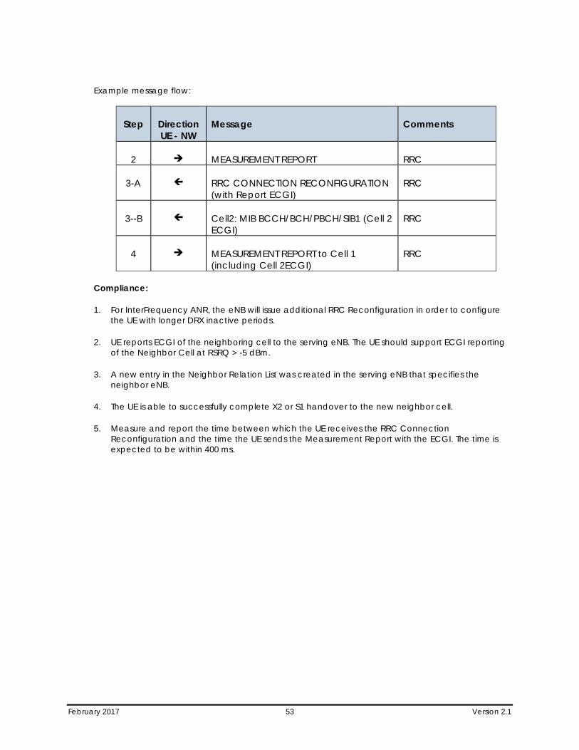
February 2017 53 Version 2.1
Example message flow:
Step Direction UE - NW
Message Comments
2 MEASUREMENT REPORT RRC
3-A RRC CONNECTION RECONFIGURATION (with Report ECGI)
RRC
3--B Cell2: MIB BCCH/BCH/PBCH/SIB1 (Cell 2 ECGI)
RRC
4 MEASUREMENT REPORT to Cell 1 (including Cell 2ECGI)
RRC
Compliance:
1. For InterFrequency ANR, the eNB will issue additional RRC Reconfiguration in order to configure the UE with longer DRX inactive periods.
2. UE reports ECGI of the neighboring cell to the serving eNB. The UE should support ECGI reporting of the Neighbor Cell at RSRQ > -5 dBm.
3. A new entry in the Neighbor Relation List was created in the serving eNB that specifies the neighbor eNB.
4. The UE is able to successfully complete X2 or S1 handover to the new neighbor cell.
5. Measure and report the time between which the UE receives the RRC Connection Reconfiguration and the time the UE sends the Measurement Report with the ECGI. The time is expected to be within 400 ms.

February 2017 54 Version 2.1
Section 6 System Loss and State Transition
6.1 System Lost – LTE System Lost in RRC_IDLE
Verify the UE’s behavior when an RRC_IDLE UE loses a Cell and subsequently finds another Cell.
Reference:
• 3GPP TS 24.301, clause 5.5.1
• 3GPP TS 36.331
Purpose:
Verify the UE’s behavior when an RRC_IDLE UE loses a Cell and subsequently finds another Cell.
Initial Condition:
1. Configure the network to have at least two active Cells.
2. Designate one Cell as Cell #1 and the other as Cell #2.
3. Configure the network to ensure that the UE will find Cell #1 first.
4. UE is powered off.
Procedure:
1. Power on the UE.
2. After the UE attaches to Cell #1, wait until the UE changes state to RRC_IDLE.
3. Force the UE to lose Cell #1.
4. The UE finds Cell #2 and initiates an attach to Cell #2.
Compliance:
1. In Step 1, verify that the UE attaches to Cell #1.
2. In Step 3, verify that the UE loses its connection to Cell #1.
3. In Step 4, verify that the UE attaches to Cell #2.
6.2 System Lost – LTE System Lost in RRC_ACTIVE
Verify the UE’s behavior when an RRC_ACTIVE UE loses connection to an Cell and subsequently finds another Cell in the same tracking area.
February 2017 55 Version 2.1
Reference:
• 3GPP TS 24.301
• 3GPP TS 24.301, clause 5.5.1, 5.6.1
• 3GPP TS 36.331
Purpose:
Verify the UE’s behavior when an RRC_ACTIVE UE loses connection to an Cell and subsequently finds another Cell in the same tracking area.
Initial Condition:
1. Configure the network to have at least two active Cell.
2. Designate one Cell as Cell #1 and the other as Cell #2.
3. Configure the network to ensure that the UE will find Cell #1 first.
4. UE supports browsing or is connected to a PC that supports HTTP browsing.
5. UE is powered off.
Procedure:
1. Power on the UE.
2. After the UE attaches to Cell #1, initiate a browser session with an available web page.
3. Cause the UE to lose Cell #1 (complete RLF failure).
4. The UE finds Cell #2.
5. Direct the browser to a different available web page.
Compliance:
1. In Step 2, verify that the UE attaches to Cell #1 and that the UE connects to the internet.
2. In Step 3, verify that the UE loses its connection to Cell #1.
3. In Step 4, verify that the UE attaches to Cell #2 and a new context is establish.
4. In Step 5, verify that the browser session still works.
6.3 Transition – Idle to Active Transition – Service Request
The UE shall successfully perform a UE initiated service request procedure.
Reference:
• 3GPP TS 24.301, clause 5.6.1
February 2017 56 Version 2.1
Purpose:
The UE shall successfully perform a UE initiated service request procedure.
Initial Condition:
1. UE is attached and in RRC_IDLE.
Procedure:
1. Trigger any data service in the UE to send Uplink data in order to trigger service request procedure.
Compliance:
1. In Step 1, verify UE successfully performs the UE initiated service request procedure and enters RRC_CONNECTED state.
6.4 Transition – Idle to Active Transition – Paging
This test verifies that the UE can successfully perform a UE initiated service request procedure after being paged.
Reference:
• 3GPP TS 24.301, clause 5.6.1
Purpose:
This test verifies that the UE can successfully perform a UE initiated service request procedure after being paged.
Initial Condition:
1. UE is attached and in RRC_IDLE.
Procedure:
1. Trigger any data service in the network to trigger a paging procedure
Compliance:
1. In Step 1, verify UE successfully responds to the paging message and enters RRC_CONNECTED state.
February 2017 57 Version 2.1
Section 7 PS Data
7.1 Ipv4 – Without Mobility – SIMO Delay of Ping
This test verifies UE meets requirements for user plane round trip delay over Ipv4.
Reference:
• 3GPP TS36.300 clause 7 and Annex A.2
• 3GPP TS24.301 clause 5
• 3GPP TS36.331 clause 5
Purpose:
This test verifies UE meets requirements for user plane round trip delay over Ipv4.
Initial Condition:
1. The Antenna configuration is SIMO.
2. The Uplink Modulation is determined by the Lab.
3. The UE is RRC_Idel.
4. The UE is connected to a network server with the Default Bearer (Best Effort) and Ipv4v6 dual stack addressing.
Procedure:
1. Initiate a one ICMP Ping from the UE to the Internet server with a payload of 32 bytes using Ipv4.
2. Measure the round trip time which includes the time to change state from RRC Idle to Connected state.
3. Repeat Steps 1 and 2 an additional 99 times, while the UE in an RRC_Connected state.
4. Calculate the average value of the round trip time for all 100 measurements.
Compliance:
1. In Step 4, verify that the average total round trip delay is less than 50 ms.
7.2 Ipv4 – Without Mobility – Transmit diversity (MIMO) Delay of Ping
This test verifies UE meets requirements for user plane round trip delay over Ipv4.
Reference:
• 3GPP TS36.300 clause 7 and Annex A.2
• 3GPP TS24.301 clause 5
February 2017 58 Version 2.1
• 3GPP TS36.331 clause 5
Purpose:
This test verifies UE meets requirements for user plane round trip delay over Ipv4.
Initial Condition:
1. The Antenna configuration is Transmit Diversity.
2. The downlink modulation level is determined by the Lab.
3. The UE is RRC_Idle.
4. The UE is connected to the Internet PDN Gateway with the Default Bearer (Best Effort) and Ipv4v6 dual stack addressing.
Procedure:
1. Initiate a one ICMP Ping to a network server.
2. Record the round trip time.
3. Repeat Steps 1 and 2 an additional 99 times.
4. Calculate the average value of the round trip time for the 100 measurements.
Compliance:
1. In Step 4, verify that the average round trip time is less than 50 msec.
7.3 Ipv4 – Without Mobility – Open Loop Multiplexing – Delay of Ping
This test verifies UE meets requirements for user plane round trip delay over Ipv4.
Reference:
• 3GPP TS36.300 clause 7 and Annex A.2,
• 3GPP TS24.301 clause 5,
• 3GPP TS36.331 clause 5
Purpose:
This test verifies UE meets requirements for user plane round trip delay over Ipv4.
Initial Condition:
1. The antenna configuration is Open Loop Spatial Multiplexing.
2. The downlink modulation level is determined by the Lab.
3. The UE is RRC_CONNECTED.
February 2017 59 Version 2.1
4. The UE is connected to the Internet PDN Gateway with the Default Bearer (Best Effort) and Ipv4v6 dual stack addressing.
Procedure:
1. Initiate a one ICMP Ping to a network server.
2. Measure the round trip time.
3. Repeat Steps 1 and 2 an additional 99 times.
4. Calculate the average value of RTT for the 100 measurements.
Compliance:
1. In Step 4, verify that the average total user plane round trip delay is less than 50 ms.
7.4 Ipv4 – Without Mobility – Close Loop Multiplexing – Delay of Ping
This test verifies UE meets requirements for user plane round trip delay over Ipv4.
Reference:
• 3GPP TS36.300 clause 7 and Annex A.2,
• 3GPP TS24.301 clause 5,
• 3GPP TS36.331 clause 5
Purpose:
This test verifies UE meets requirements for user plane round trip delay over Ipv4.
Initial Condition:
1. The antenna configuration is Close Loop Spatial Multiplexing.
2. The downlink modulation level is determined by the Lab.
3. The UE is RRC_CONNECTED.
4. The UE is connected to the Internet PDN Gateway with the Default Bearer (Best Effort) and Ipv4v6 dual stack addressing.
Procedure:
1. Initiate a one ICMP Ping to a network server.
2. Measure the round trip time.
3. Repeat Steps 1 and 2 an additional 99 times.
4. Calculate the average value of RTT for the 100 measurements.
February 2017 60 Version 2.1
Compliance:
1. In Step 4, verify that the average total user plane round trip delay is less than 50 ms.
7.5 Ipv6 – Without Mobility – SIMO Delay of Ping
This test verifies UE meets requirements for user plane round trip delay over Ipv6.
Reference:
• 3GPP TS36.300 clause 7 and Annex A.2,
• 3GPP TS24.301 clause 5,
• 3GPP TS36.331 clause 5
Purpose:
This test verifies UE meets requirements for user plane round trip delay over Ipv6.
Initial Condition:
1. The Antenna configuration is SIMO.
2. The Uplink Modulation is determined by the Lab.
3. The UE is RRC_CONNECTED.
4. The UE is connected to the Internet PDN Gateway with the Default Bearer (Best Effort) and Ipv4v6 dual stack addressing.
Procedure:
1. Initiate a one ICMP Ping to a network server.
2. Measure the round trip time.
3. Repeat Steps 1 and 2 an additional 99 times.
4. Calculate the average value of the round trip time for all 100 measurements.
Compliance:
1. In Step 4, verify that the average total round trip delay is less than 50 ms.
7.6 Ipv6 – Without Mobility – Transmit Diversity (MIMO) Delay of Ping
This test verifies UE meets requirements for user plane round trip delay over Ipv6.
Reference:
• 3GPP TS36.300 clause 7 and Annex A.2,
• 3GPP TS24.301 clause 5,
February 2017 61 Version 2.1
• 3GPP TS36.331 clause 5
Purpose:
This test verifies UE meets requirements for user plane round trip delay over Ipv6.
Initial Condition:
1. The Antenna configuration is Transmit Diversity.
2. The downlink modulation level is determined by the Lab.
3. The UE is RRC_CONNECTED.
4. The UE is connected to the Internet PDN Gateway with the Default Bearer (Best Effort) and Ipv4v6 dual stack addressing.
Procedure:
1. Initiate a one ICMPv6 Ping to a network server using Ipv6.
2. Record the round trip time.
3. Repeat Steps 1 and 2 an additional 99 times.
4. Calculate the average value of the round trip time for the 100 measurements.
Compliance:
1. In Step 4, verify that the average round trip time is less than 50 msec.
7.7 Ipv6 – Without Mobility – Open Loop Multiplexing – Delay of Ping
This test verifies UE meets requirements for user plane round trip delay over Ipv6.
Reference:
• 3GPP TS36.300 clause 7 and Annex A.2
• 3GPP TS24.301 clause 5
• 3GPP TS36.331 clause 5
Purpose:
This test verifies UE meets requirements for user plane round trip delay over Ipv6.
Initial Condition:
1. The antenna configuration is Open Loop Spatial Multiplexing.
2. The downlink modulation level is determined by the Lab.
3. The UE is RRC_CONNECTED.
February 2017 62 Version 2.1
4. The UE is connected to the Internet PDN Gateway with the Default Bearer (Best Effort) and Ipv4v6 dual stack addressing.
Procedure:
1. Initiate a one ICMPv6 Ping to a network server using Ipv6.
2. Measure the round trip time.
3. Repeat Steps 1 and 2 an additional 99 times.
4. Calculate the average value of RTT for the 100 measurements.
Compliance:
1. In Step 4, verify that the average total user plane round trip delay is less than 50 ms.
7.8 Ipv6 – Without Mobility – Close Loop Multiplexing – Delay of Ping
This test verifies UE meets requirements for user plane round trip delay over Ipv6.
Reference:
• 3GPP TS36.300 clause 7 and Annex A.2
• 3GPP TS24.301 clause 5
• 3GPP TS36.331 clause 5
Purpose:
This test verifies UE meets requirements for user plane round trip delay over Ipv6.
Initial Condition:
1. The antenna configuration is Closed Loop Spatial Multiplexing.
2. The downlink modulation level is determined by the Lab.
3. The UE is RRC_CONNECTED.
4. The UE is connected to the Internet PDN Gateway with the Default Bearer (Best Effort) and Ipv4v6 dual stack addressing.
Procedure:
1. Initiate a one ICMPv6 Ping to a network server using Ipv6.
2. Measure the round trip time.
3. Repeat Steps 1 and 2 an additional 99 times.
4. Calculate the average value of RTT for the 100 measurements.
February 2017 63 Version 2.1
Compliance:
1. In Step 4, verify that the average total user plane round trip delay is less than 50 ms.
7.9 PDN Connectivity Request –ESM Information transfer flag=TRUE
In case if UE wants to include the APN name in PDN Connectivity request and/or usage of default APN requires Authentication – UE shall include ESM Information transfer flag and set it to TRUE
Reference:
• TS.11 (32.1.1)
• 3GPP TS 24.301, clause 6.5.1.2
Purpose:
To verify that UE is correctly setting ESM Information transfer flag and additional information like APN name and Authentication information is exchanged using ESM INFORMATION procedure
Initial Condition:
1. UE is powered off.
2. APN name is explicitly configured on UE side.
3. Usage of APN requires Authentication.
4. The necessary Authentication Username/password is configured on UE side.
Procedure:
1. Power on the UE and verify that the UE sends ESM Information Transfer flag and set it to TRUE in “PDN CONNECTIVITY REQUEST.”
2. The network shall respond to the UE with a ESM INFORMATION REQUEST message.
3. After UE replies with ESM INFORMATION RESPONSE containing APN IE and PCO (Protocol Configuration Options), the network shall respond to the UE with an "RRCConnectionReconfiguration" message that contains the “EPS Radio Bearer Identity” and the APN for a default bearer.
Compliance:
1. After Step 3: Verify that PDN Connectivity is functional to the network where this APN gives access to (e.g. loading a designated HTML page, which is only accessible via this network).
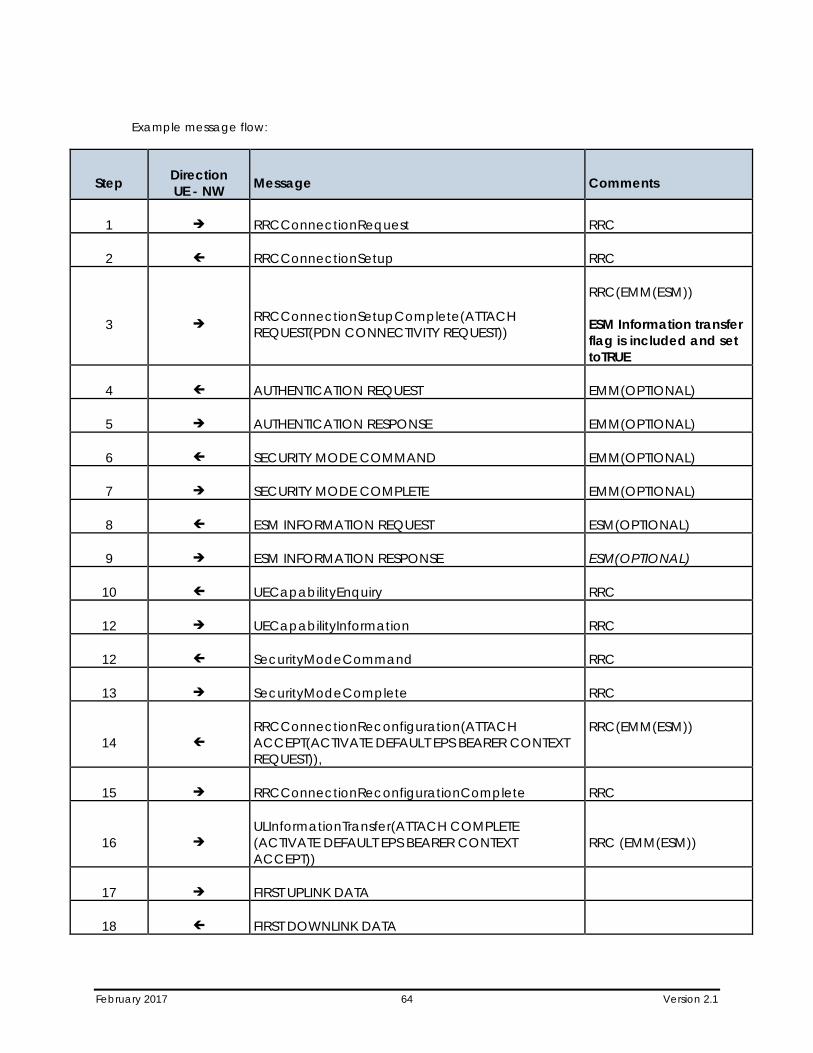
February 2017 64 Version 2.1
Example message flow:
Step Direction UE - NW Message Comments
1 RRCConnectionRequest RRC
2 RRCConnectionSetup RRC
3 RRCConnectionSetupComplete(ATTACH REQUEST(PDN CONNECTIVITY REQUEST))
RRC(EMM(ESM))
ESM Information transfer flag is included and set toTRUE
4 AUTHENTICATION REQUEST EMM(OPTIONAL)
5 AUTHENTICATION RESPONSE EMM(OPTIONAL)
6 SECURITY MODE COMMAND EMM(OPTIONAL)
7 SECURITY MODE COMPLETE EMM(OPTIONAL)
8 ESM INFORMATION REQUEST ESM(OPTIONAL)
9 ESM INFORMATION RESPONSE ESM(OPTIONAL)
10 UECapabilityEnquiry RRC
12 UECapabilityInformation RRC
12 SecurityModeCommand RRC
13 SecurityModeComplete RRC
14 RRCConnectionReconfiguration(ATTACH ACCEPT(ACTIVATE DEFAULT EPS BEARER CONTEXT REQUEST)),
RRC(EMM(ESM))
15 RRCConnectionReconfigurationComplete RRC
16 ULInformationTransfer(ATTACH COMPLETE (ACTIVATE DEFAULT EPS BEARER CONTEXT ACCEPT))
RRC (EMM(ESM))
17 FIRST UPLINK DATA
18 FIRST DOWNLINK DATA

February 2017 65 Version 2.1
7.10 PDN Connectivity Reject, ESM Cause #27 Missing or Unknown APN
Verify that the UE inform the user of reject of PDN connectivity establishment
Reference:
• TS.11 (32.1.2)
• 3GPP TS 24.301, section 6.5.1.4
Purpose:
To ensure that the UE is not able to achieve PDN connectivity with an unknown APN.
Initial Condition:
1. UE is in EMM-REGISTERED state.
Procedure:
1. Initiate a secondary PDN connectivity request, for example by means of an embedded web browser or DUN connection and specify explicitly an APN name different than default one.
2. MME reject PDN CONNECTIVITY REQUEST with cause #27 “Missing or unknown APN”
Compliance:
1. At Step 2 – Verify that the user is informed for unsuccessful PDN Connectivity request
Example message flow:
Step Direction UE – NW Message Comments
1 RRCConnectionRequest RRC(Optional)
2 RRCConnectionSetup RRC(Optional)
3 RRCConnectionSetupComplete(SERVICE REQUEST) RRC(EMM)(Optional)
4 IDENTITY REQUEST EMM(Optional)
5 IDENTITY RESPONSE EMM(Optional)
6 AUTHENTICATION REQUEST EMM(Optional)
7 AUTHENTICATION RESPONSE EMM(Optional)
8 SECURITY MODE COMMAND EMM(Optional)

February 2017 66 Version 2.1
Step Direction UE – NW Message Comments
9 SECURITY MODE COMPLETE EMM(Optional)
10 SecurityModeCommand RRC(Optional)
11 SecurityModeComplete RRC(Optional)
12 RRCConnectionReconfiguration RRC(Optional)
13 RRCConnectionReconfigurationComplete RRC(Optional)
14 PDN CONNECTIVITY REQUEST ESM
15 PDN CONNECTIVITY REJECT, ESM CAUSE 27 ESM
Note: RRC procedures are optional in case if UE is in RRC_CONNECTED state.
7.11 PDN Disconnect Procedure – UE Initiated
This test verifies that the UE can successfully disconnect from one PDN (not the last).
Reference:
• 3GPP TS 24.301, clauses 6.5.2
Purpose:
To ensure the UE initiated PDN disconnect procedure works.
Initial Condition:
UE is attached to at least two PDNs and is in RRC IDLE state.
Procedure:
1. UE initiates a PDN disconnect to one PDN only.
Compliance:
1. Verify that the PDN disconnect procedure is successful.
7.12 Detach Procedure – Network Initiated
This test verifies that the UE can successfully detach from the network upon receipt of a Detach Request from the network.
Reference:
• 3GPP TS 24.301, clauses 5.5.2, 6.4.4 and 6.5.4
February 2017 67 Version 2.1
• 3GPP TS 23.401, clauses 5.4.4 and 5.3.8
Purpose:
This test verifies that the UE can successfully detach from the network upon receipt of a Detach Request from the network.
Initial Condition:
1. UE is attached to the network.
Procedure:
1. Network initiates a Detach Request.
2. UE responds with the Detach Acknowledge.
Compliance:
1. In Step 2, verify that the UE is detached from the network.
7.13 Multiple PDN Connections – Second PDN Connectivity Request (UE Initiated)
Verify that the UE can successfully activate a second PDN Connection
Reference:
• TS.11 (32.1.3)
• 3GPP TS 24.301, section 6.5.1
• 3GPP TS 23.401, section 5.10
Purpose:
To ensure the UE is able to have multiple PDN connections correctly established.
Initial Condition:
1. UE is in EMM-REGISTERED state.
2. UE subscription has multiple APNs.
Procedure:
1. Initiate a second PDN connectivity request, for example by means of an embedded web browser or DUN connection and specify explicitly an APN name different than default one.
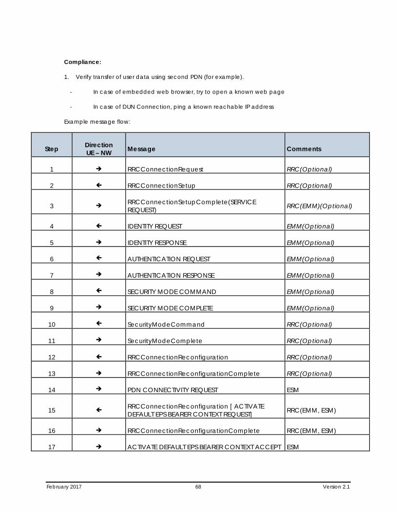
February 2017 68 Version 2.1
Compliance:
1. Verify transfer of user data using second PDN (for example).
- In case of embedded web browser, try to open a known web page
- In case of DUN Connection, ping a known reachable IP address
Example message flow:
Step Direction UE – NW Message Comments
1 RRCConnectionRequest RRC(Optional)
2 RRCConnectionSetup RRC(Optional)
3 RRCConnectionSetupComplete(SERVICE REQUEST) RRC(EMM)(Optional)
4 IDENTITY REQUEST EMM(Optional)
5 IDENTITY RESPONSE EMM(Optional)
6 AUTHENTICATION REQUEST EMM(Optional)
7 AUTHENTICATION RESPONSE EMM(Optional)
8 SECURITY MODE COMMAND EMM(Optional)
9 SECURITY MODE COMPLETE EMM(Optional)
10 SecurityModeCommand RRC(Optional)
11 SecurityModeComplete RRC(Optional)
12 RRCConnectionReconfiguration RRC(Optional)
13 RRCConnectionReconfigurationComplete RRC(Optional)
14 PDN CONNECTIVITY REQUEST ESM
15 RRCConnectionReconfiguration [ ACTIVATE DEFAULT EPS BEARER CONTEXT REQUEST] RRC(EMM, ESM)
16 RRCConnectionReconfigurationComplete RRC(EMM, ESM)
17 ACTIVATE DEFAULT EPS BEARER CONTEXT ACCEPT ESM
February 2017 69 Version 2.1
7.14 Multiple PDN Connections – Second PDN Connectivity Disconnect
Verify that the UE can successfully deactivate second PDN Connection.
Reference:
• TS.11 (32.1.4)
• 3GPP TS 24.301, section 6.5.2
• 3GPP TS 23.401, section 5.10
Purpose:
To ensure that the UE is able to deactivate a second PDN Connection correctly while maintaining the former PDN Connection active.
Initial Condition:
1. UE is in EMM-REGISTERED state.
2. UE has already two active PDN Connections by means of, respectively, an externally initiated packet data session and an embedded browser session.
Procedure:
1. Verify that an externally initiated packet data session is already established.
2. Verify that an embedded browser session is already established.
3. Manage to deactivate one of the primary PDP contexts (e.g. Terminate DUN session).
4. Verify that DUN session is not active.
5. Verify that the other PDP connection is still active (e.g. try to open a known web page).
Compliance:
1. The UE shall be able to deactivate one of the PDN connections while maintaining the other PDN Connection active.
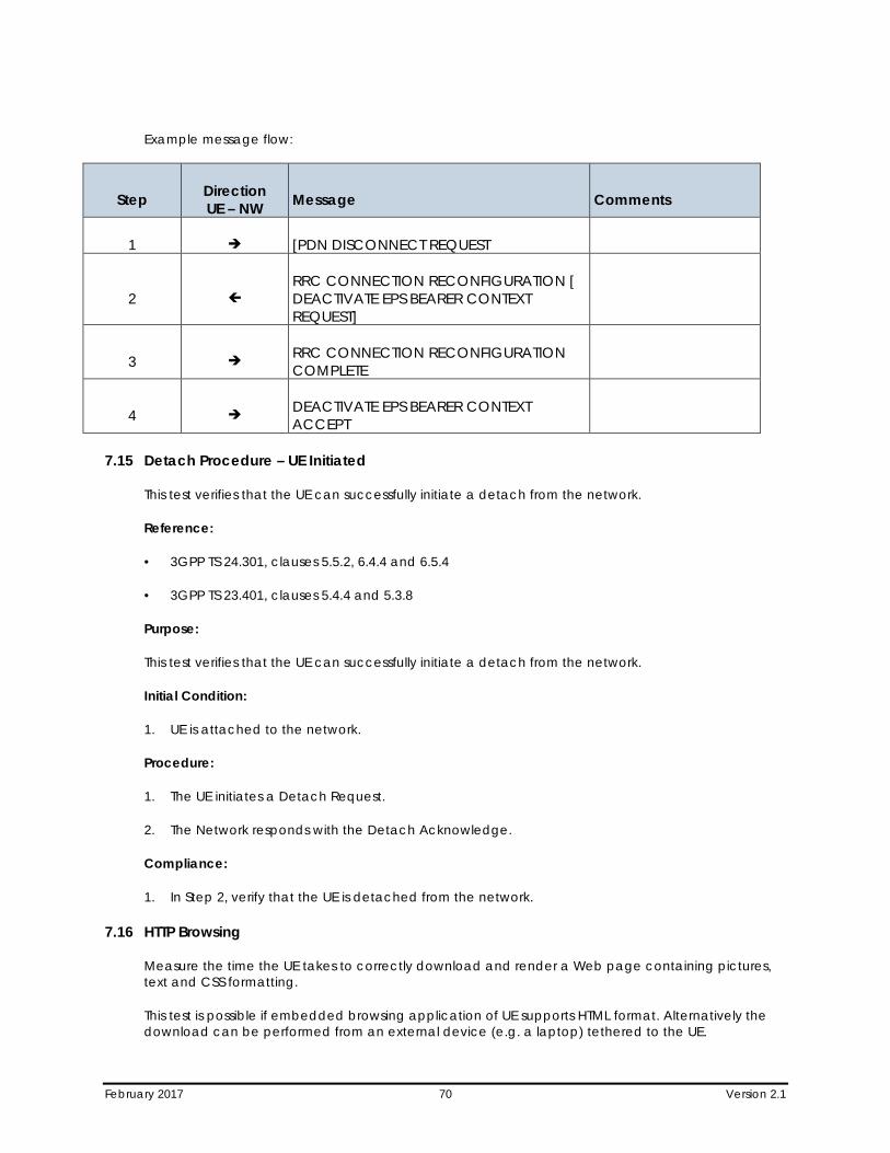
February 2017 70 Version 2.1
Example message flow:
Step Direction UE – NW Message Comments
1 [PDN DISCONNECT REQUEST
2 RRC CONNECTION RECONFIGURATION [ DEACTIVATE EPS BEARER CONTEXT REQUEST]
3 RRC CONNECTION RECONFIGURATION COMPLETE
4 DEACTIVATE EPS BEARER CONTEXT ACCEPT
7.15 Detach Procedure – UE Initiated
This test verifies that the UE can successfully initiate a detach from the network.
Reference:
• 3GPP TS 24.301, clauses 5.5.2, 6.4.4 and 6.5.4
• 3GPP TS 23.401, clauses 5.4.4 and 5.3.8
Purpose:
This test verifies that the UE can successfully initiate a detach from the network.
Initial Condition:
1. UE is attached to the network.
Procedure:
1. The UE initiates a Detach Request.
2. The Network responds with the Detach Acknowledge.
Compliance:
1. In Step 2, verify that the UE is detached from the network.
7.16 HTTP Browsing
Measure the time the UE takes to correctly download and render a Web page containing pictures, text and CSS formatting.
This test is possible if embedded browsing application of UE supports HTML format. Alternatively the download can be performed from an external device (e.g. a laptop) tethered to the UE.
February 2017 71 Version 2.1
Reference:
• TS.11 (32.2.2)
• 3GPP TS 36.331
Purpose:
To measure the UE performance in case of repeated downloads of small size files, such as Ipv4 and Ipv6 addressable HTML pages.
Two test procedures are defined, one to give an indication of the download speed and one to give an indication of the download speed and the time taken to perform state transitions.
To help measure the download size and speed, tools such as in https://gtmetrix.com, Android’s adb shell “busybox wget” command, or Chrome’s development menu for network could help.
Initial Condition:
1. The UE is attached to the network and has an always-on IP connectivity after establishing a default EPS bearer during Network Attachment.
2. Set up the browser to ensure that the page is downloaded from the network each time and not just loaded from the browser cache
Procedure:
1. Manage on the UE (or on the external device) to download the same reference web page (preferably facebook.com or an operator endorsed reference web page)
a. Repeat rapidly for 10 times in a row.
b. For the second part, repeat 3 times in a row leaving a sufficient pause between each download to revert to idle mode.
2. Verify than the download of the page is correct each time (number of elements).
3. Measure the time to download the reference web page and calculate the average download time per page, for steps 1.a and 1.b as separate averages.
4. Repeat with an Ipv4 or Ipv6 addressable reference web page (whichever was not previously used).
Compliance:
The UE shall be able to download the reference Web pages. Record the duration of the web page download. Also record the URL of the reference page used for the test.
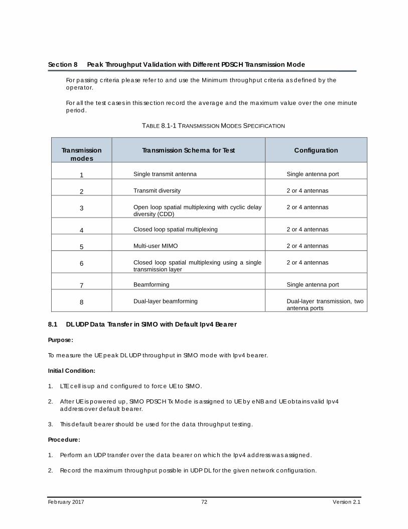
February 2017 72 Version 2.1
Section 8 Peak Throughput Validation with Different PDSCH Transmission Mode
For passing criteria please refer to and use the Minimum throughput criteria as defined by the operator.
For all the test cases in this section record the average and the maximum value over the one minute period.
TABLE 8.1-1 TRANSMISSION MODES SPECIFICATION
Transmission modes
Transmission Schema for Test Configuration
1 Single transmit antenna Single antenna port
2 Transmit diversity 2 or 4 antennas
3 Open loop spatial multiplexing with cyclic delay diversity (CDD)
2 or 4 antennas
4 Closed loop spatial multiplexing 2 or 4 antennas
5 Multi-user MIMO 2 or 4 antennas
6 Closed loop spatial multiplexing using a single transmission layer
2 or 4 antennas
7 Beamforming Single antenna port
8 Dual-layer beamforming Dual-layer transmission, two antenna ports
8.1 DL UDP Data Transfer in SIMO with Default Ipv4 Bearer
Purpose:
To measure the UE peak DL UDP throughput in SIMO mode with Ipv4 bearer.
Initial Condition:
1. LTE cell is up and configured to force UE to SIMO.
2. After UE is powered up, SIMO PDSCH Tx Mode is assigned to UE by eNB and UE obtains valid Ipv4 address over default bearer.
3. This default bearer should be used for the data throughput testing.
Procedure:
1. Perform an UDP transfer over the data bearer on which the Ipv4 address was assigned.
2. Record the maximum throughput possible in UDP DL for the given network configuration.
February 2017 73 Version 2.1
Compliance:
1. The UE peak Ipv4 throughput over the DL SIMO configuration for the given network configuration shall be recorded.
8.2 DL UDP Data Transfer in Tx Diversity with Default Ipv4 Bearer
Purpose:
To measure the UE peak DL UDP throughput in Tx Diversity mode with Ipv4 bearer.
Initial Condition:
1. LTE cell is up and configured to support Transmit Diversity schema.
2. After UE is powered up, Tx Diversity PDSCH Tx Mode is assigned to UE by eNB and UE obtains valid Ipv4 address over default bearer.
3. This default bearer should be used for the data throughput testing.
Procedure:
1. Perform an UDP transfer over the data bearer on which the Ipv4 address was assigned.
2. Record the maximum throughput possible in UDP DL for the given network configuration.
Compliance:
1. The UE peak Ipv4 throughput over the DL Tx Diversity configuration for the given network configuration shall be recorded.
8.3 DL UDP Data Transfer in Open Loop MIMO (TM=3) with Default Ipv4 Bearer
Purpose:
To measure the UE peak DL UDP throughput in open loop MIMO mode with Ipv4 bearer.
Initial Condition:
1. LTE cell is up configured to support OLSM.
2. After UE is powered up, open loop MIMO PDSCH Tx Mode (TM=3) is assigned to UE by eNB and UE obtains valid Ipv4 address over default bearer.
3. This default bearer should be used for the data throughput testing.
Procedure:
1. Perform an UDP transfer over the data bearer on which the Ipv4 address was assigned.
2. Record the maximum throughput possible in UDP DL for the given network configuration.
Compliance:
February 2017 74 Version 2.1
1. The UE peak Ipv4 throughput over the DL open loop MIMO configuration for the given network configuration shall be recorded.
8.4 DL UDP Data Transfer in Close Loop MIMO (TM=4) with Default Ipv4 Bearer
Purpose:
To measure the UE peak DL UDP throughput in close loop MIMO mode with Ipv4 bearer.
Initial Condition:
1. LTE cell is up and configured to support CLSM.
2. After UE is powered up, close loop MIMO PDSCH Tx Mode (TM=4) is assigned to UE by eNB and UE obtains valid Ipv4 address over default bearer.
3. This default bearer should be used for the data throughput testing.
Procedure:
1. Perform an UDP transfer over the data bearer on which the Ipv4 address was assigned.
2. Record the maximum throughput possible in UDP DL for the given network configuration.
Compliance:
The UE peak Ipv4 throughput over the DL close loop MIMO configuration for the given network configuration shall be recorded.
8.5 DL FTP Data Transfer in SIMO with Default Ipv4 Bearer
Purpose:
To measure the UE peak DL FTP throughput in SIMO mode with Ipv4 bearer.
Initial Condition:
1. LTE cell is up configure to support SIMO.
2. After UE is powered up, SIMO PDSCH Tx Mode is assigned to UE by eNB and UE obtains valid Ipv4 address over default bearer.
3. This default bearer should be used for the data throughput testing.
Procedure:
1. Perform an FTP transfer over the data bearer on which the Ipv4 address was assigned.
2. Record the maximum throughput possible in FTP DL for the given network configuration.
February 2017 75 Version 2.1
Compliance:
1. The UE peak Ipv4 throughput over the DL SIMO configuration for the given network configuration shall be recorded.
8.6 DL FTP Data Transfer in Tx Diversity with Default Ipv4 Bearer
Purpose:
To measure the UE peak DL FTP throughput in Tx Diversity mode with Ipv4 bearer.
Initial Condition:
1. LTE cell is up and configured to support TXD.
2. After UE is powered up, Tx Diversity PDSCH Tx Mode is assigned to UE by eNB and UE obtains valid Ipv4 address over default bearer.
3. This default bearer should be used for the data throughput testing.
Procedure:
1. Perform an FTP transfer over the data bearer on which the Ipv4 address was assigned.
2. Record the maximum throughput possible in FTP DL for the given network configuration.
Compliance:
1. The UE peak Ipv4 throughput over the DL Tx Diversity configuration for the given network configuration shall be recorded.
8.7 DL FTP Data Transfer in Open Loop MIMO (TM=3) with Default Ipv4 Bearer
Purpose:
To measure the UE peak DL FTP throughput in open loop MIMO mode with Ipv4 bearer.
Initial Condition:
1. LTE cell is up and configured to support OLSM.
2. After UE is powered up, open loop MIMO PDSCH Tx Mode (TM=3) is assigned to UE by eNB and UE obtains valid Ipv4 address over default bearer.
3. This default bearer should be used for the data throughput testing.
Procedure:
1. Perform an FTP transfer over the data bearer on which the Ipv4 address was assigned.
2. Record the maximum throughput possible in FTP DL for the given network configuration.
February 2017 76 Version 2.1
Compliance:
1. The UE peak Ipv4 throughput over the DL open loop MIMO configuration for the given network configuration shall be recorded.
8.8 DL FTP Data Transfer in Close Loop MIMO (TM=4) with Default Ipv4 Bearer
Purpose:
To measure the UE peak DL FTP throughput in close loop MIMO mode with Ipv4 bearer.
Initial Condition:
1. LTE cell is up and configured to support CLSM.
2. After UE is powered up, close loop MIMO PDSCH Tx Mode (TM=4) is assigned to UE by eNB and UE obtains valid Ipv4 address over default bearer.
3. This default bearer should be used for the data throughput testing.
Procedure:
1. Perform an FTP transfer over the data bearer on which the Ipv4 address was assigned.
2. Record the maximum throughput possible in FTP DL for the given network configuration.
Compliance:
1. The UE peak Ipv4 throughput over the DL close loop MIMO configuration for the given network configuration shall be recorded.
8.9 UL UDP Data Transfer with Default Ipv4 Bearer
Purpose:
To measure the UE peak UL UDP throughput with Ipv4 bearer.
Initial Condition:
1. LTE cell is up and after UE is powered up, UE obtains valid Ipv4 address over default bearer. This default bearer should be used for the data throughput testing.
Procedure:
1. Perform an UL UDP transfer over the data bearer on which the Ipv4 address was assigned.
2. Record the maximum throughput possible in UL UDP for the given network configuration.
Compliance:
1. The UE peak Ipv4 UL throughput for the given network configuration shall be recorded.
February 2017 77 Version 2.1
8.10 UL FTP Data Transfer with Default Ipv4 Bearer
Purpose:
To measure the UE peak UL FTP throughput with Ipv4 bearer.
Initial Condition:
1. LTE cell is up and after UE is powered up, UE obtains valid Ipv4 address over default bearer. This default bearer should be used for the data throughput testing.
Procedure:
1. Perform an UL FTP transfer over the data bearer on which the Ipv4 address was assigned.
2. Record the maximum throughput possible in UL FTP for the given network configuration.
Compliance:
The UE peak Ipv4 UL throughput for the given network configuration shall be recorded.
8.11 DL UDP Data Transfer in SIMO with Default Ipv6 Bearer
Purpose:
To measure the UE peak DL UDP throughput in SIMO mode with Ipv6 bearer.
Initial Condition:
1. LTE cell is up and configure to support SIMO.
2. After UE is powered up, SIMO PDSCH Tx Mode is assigned to UE by eNB and UE obtains valid Ipv6 address over default bearer. This default bearer should be used for the data throughput testing.
Procedure:
1. Perform an UDP transfer over the data bearer on which the Ipv6 address was assigned.
2. Record the maximum throughput possible in UDP DL for the given network configuration.
Compliance:
The UE peak Ipv6 throughput over the DL SIMO configuration for the given network configuration shall be recorded.
8.12 DL UDP Data Transfer in Tx Diversity with Default Ipv6 Bearer
Purpose:
To measure the UE peakDL UDP throughput in Tx Diversity mode with Ipv6 bearer.
Initial Condition:
1. LTE cell is up and configured to support TXD.
February 2017 78 Version 2.1
2. After UE is powered up, Tx Diversity PDSCH Tx Mode is assigned to UE by eNB and UE obtains valid Ipv6 address over default bearer. This default bearer should be used for the data throughput testing.
Procedure:
1. Perform an UDP transfer over the data bearer on which the Ipv6 address was assigned.
Record the maximum throughput possible in UDP DL for the given network configuration.
Compliance:
1. The UE peak Ipv6 throughput over the DL Tx Diversity configuration for the given network configuration shall be recorded.
8.13 DL UDP Data Transfer in Open Loop MIMO (TM=3) with Default Ipv6 Bearer
Purpose:
To measure the UE peak DL UDP throughput in open loop MIMO mode with Ipv6 bearer.
Initial Condition:
1. LTE cell is up and configured to support OLSM.
2. After UE is powered up, open loop MIMO PDSCH Tx Mode (TM=3) is assigned to UE by eNB and UE obtains valid Ipv6 address over default bearer. This default bearer should be used for the data throughput testing.
Procedure:
1. Perform an UDP transfer over the data bearer on which the Ipv6 address was assigned.
2. Record the maximum throughput possible in UDP DL for the given network configuration.
Compliance:
1. The UE peak Ipv6 throughput over the DL open loop MIMO configuration for the given network configuration shall be recorded.
8.14 DL UDP Data Transfer in Close Loop MIMO (TM=4) with Default Ipv6 Bearer
Purpose:
To measure the UE peak DL UDP throughput in close loop MIMO mode with Ipv6 bearer.
Initial Condition:
1. LTE cell is up and configured to support CLSM.
2. After UE is powered up, close loop MIMO PDSCH Tx Mode (TM=4) is assigned to UE by eNB and UE obtains valid Ipv6 address over default bearer. This default bearer should be used for the data throughput testing.
February 2017 79 Version 2.1
Procedure:
1. Perform an UDP transfer over the data bearer on which the Ipv6 address was assigned.
2. Record the maximum throughput possible in UDP DL for the given network configuration.
Compliance:
The UE peak Ipv6 throughput over the DL close loop MIMO configuration for the given network configuration shall be recorded.
8.15 DL FTP Data Transfer in SIMO with Default Ipv6 Bearer
Purpose:
To measure the UE peak DL FTP throughput in SIMO mode with Ipv6 bearer.
Initial Condition:
1. LTE cell is up and configure to support SIMO.
2. After UE is powered up, SIMO PDSCH Tx Mode is assigned to UE by eNB and UE obtains valid Ipv6 address over default bearer. This default bearer should be used for the data throughput testing.
Procedure:
1. Perform an FTP transfer over the data bearer on which the Ipv6 address was assigned.
2. Record the maximum throughput possible in FTP DL for the given network configuration.
Compliance:
1. The UE peak Ipv6 throughput over the DL SIMO configuration for the given network configuration shall be recorded.
8.16 DL FTP Data Transfer in Tx Diversity with Default Ipv6 Bearer
Purpose:
To measure the UE peak DL FTP throughput in Tx Diversity mode with Ipv6 bearer.
Initial Condition:
1. LTE cell is up and configured to support TXD.
2. After UE is powered up, Tx Diversity PDSCH Tx Mode is assigned to UE by eNB and UE obtains valid Ipv6 address over default bearer. This default bearer should be used for the data throughput testing.
Procedure:
1. Perform an FTP transfer over the data bearer on which the Ipv6 address was assigned.
2. Record the maximum throughput possible in FTP DL for the given network configuration.
February 2017 80 Version 2.1
Compliance:
1. The UE peak Ipv6 throughput over the DL Tx Diversity configuration for the given network configuration shall be recorded.
8.17 DL FTP Data Transfer in Open Loop MIMO (TM=3) with Default Ipv6 Bearer
Purpose:
To measure the UE peak DL FTP throughput in open loop MIMO mode with Ipv6 bearer.
Initial Condition:
1. LTE cell is up and configured to support OLSM.
2. AFTER UE is powered up, open loop MIMO PDSCH Tx Mode (TM=3) is assigned to UE by eNB and UE obtains valid Ipv6 address over default bearer. This default bearer should be used for the data throughput testing.
Procedure:
1. Perform an FTP transfer over the data bearer on which the Ipv6 address was assigned.
2. Record the maximum throughput possible in FTP DL for the given network configuration.
Compliance:
1. The UE peak Ipv6 throughput over the DL open loop MIMO configuration for the given network configuration shall be recorded.
8.18 DL FTP Data Transfer in Close Loop MIMO (TM=4) with Default Ipv6 Bearer
Purpose:
To measure the UE peak DL FTP throughput in close loop MIMO mode with Ipv6 bearer.
Initial Condition:
1. LTE cell is up and configured to support CLSM.
2. AFTER UE is powered up, close loop MIMO PDSCH Tx Mode (TM=4) is assigned to UE by eNB and UE obtains valid Ipv6 address over default bearer. This default bearer should be used for the data throughput testing.
Procedure:
1. Perform an FTP transfer over the data bearer on which the Ipv6 address was assigned.
2. Record the maximum throughput possible in FTP DL for the given network configuration.
Compliance:
1. The UE peak Ipv6 throughput over the DL close loop MIMO configuration for the given network configuration shall be recorded.

February 2017 81 Version 2.1
8.19 UL UDP Data Transfer with Default Ipv6 Bearer
Purpose:
To measure the UE peak UL UDP throughput with Ipv6 bearer.
Initial Condition:
1. LTE cell is up and after UE is powered up, UE obtains valid Ipv6 address over default bearer. This default bearer should be used for the data throughput testing.
Procedure:
1. Perform an UL UDP transfer over the data bearer on which the Ipv6 address was assigned.
2. Record the maximum throughput possible in UL UDP for the given network configuration.
Compliance:
1. The UE peak Ipv6 UL throughput for the given network configuration shall be recorded.
8.20 UL FTP Data Transfer with Default Ipv6 Bearer
Purpose:
To measure the UE peak UL FTP throughput with Ipv6 bearer.
Initial Condition:
1. LTE cell is up and after UE is powered up, UE obtains valid Ipv6 address over default bearer. This default bearer should be used for the data throughput testing.
Procedure:
1. Perform an UL FTP transfer over the data bearer on which the Ipv6 address was assigned.
2. Record the maximum throughput possible in UL FTP for the given network configuration.
Compliance:
1. The UE peak Ipv6 UL throughput for the given network configuration shall be recorded.
February 2017 82 Version 2.1
Section 9 Dedicated Bearer
9.1 Network Initiated Dedicated Ipv4 Bearer Establishment and Data Connectivity
The purpose of this test is to verify default and dedicated bearer establishment and data connectivity.
Reference:
• 3GPP2 TS 24.301
Purpose:
To ensure the UE can successfully establish a dedicated bearer in addition to the default bearer.
Initial Configuration:
1. UE establishes a default EPS bearer to an Ipv4 PDN.
Procedure:
1. Trigger network establishment of a dedicated Ipv4 bearer.
2. Initiate a UDP traffic on each default and dedicated bearer and on the UL and DL directions.
Compliance:
1. UE establishes and maintains data connectivity with both the default and dedicated bearers.
9.2 Network Initiated Dedicated Ipv6 Bearer Establishment and Data Connectivity
The purpose of this test is to verify default and dedicated bearer establishment and data connectivity.
Reference:
• 3GPP2 TS 24.301
Purpose:
To ensure the UE can successfully establish a dedicated bearer in addition to the default bearer.
Initial Configuration:
1. UE establishes a default EPS bearer to an Ipv6 PDN.
Procedure:
1. Trigger network establishment of a dedicated Ipv6 bearer.
2. Initiate a UDP traffic on each default and dedicated bearer and on the UL and DL directions.

February 2017 83 Version 2.1
Compliance:
1. UE establishes and maintains data connectivity with both the default and dedicated bearers.
February 2017 84 Version 2.1
Section 10 DRX
10.1 Long and Short DRX
The purpose of this test is to verify that when the UE is configured with DRX, the UE shall correctly apply the DRX configuration as specified by the eNB in the Radio Resource Configuration.
Reference:
• 3GPP2 TS 36.523-1 sub-clause 7.1.6.1 • 3GPP reference 36.331 rev. 8.8.0, Annex B1
Purpose:
To ensure the UE shall correctly apply the DRX configuration as specified by the eNB.
Initial Configuration:
1. Ensure that the UE is set to support Long + Short DRX.
2. Set the Long+Short DRX configuration on the eNB
3. Sample of RRC timers for long+shortDRX: onDurationTimer=psf10, drx-InactivityTimer=psf10, longDRX-CycleStartOffset=sf1280, shortDRX=sf640, drxShortCycleTimer=1 or per Operator Market Endorsement.
4. UE is in RRC_CONNECTED State.
Procedure:
1. Start a DL ping, from Network to UE, at an interval of 1 second and record the Round Trip Time (RTT) for at least 60 seconds.
2. Verify that the RTT is observed to be longer and variable than the RTT values recorded in a reference test when the DRX is not turned ON.
Compliance:
1. UE supports DRX functionality.
February 2017 85 Version 2.1
Section 11 TDD Specific Test Cases
11.1 Simultaneous UL and DL Data throughput with Default IPV4 Bearer
Purpose:
To measure the UE peak simultaneous UL and DL UDP throughput in close loop MIMO mode with Ipv4 bearer using applicable TDD Frame Configuration and Special Subframe Configuration(s) per market endorsement of target operator.
This test case must be executed for all TDD Frame Configuration and Special Subframe Configuration combinations listed in the market endorsement of target operator.
Reference:
• 3GPP TS 36.331
Initial Condition:
1. UE is successfully attached to eNB and assigned closed loop MIMO PDSCH Tx Mode (TM=4).
2. UE obtains valid Ipv4 address over default bearer.
3. The default bearer should be used for the data throughput testing.
4. The serving cell must be configured with Frame Configuration and Special Subframe Configuration per market endorsement of target operator.
Procedure:
1. Perform a UDP UL transfer over the data bearer on which the Ipv4 address was assigned.
a. Record the maximum throughput achieved in UDP UL for Frame Configuration and Special Subframe Configuration.
2. Perform a UDP DL transfer over the data bearer on which the Ipv4 address was assigned.
a. Record the maximum throughput achieved in UDP DL for Frame Configuration and Special Subframe Configuration.
Compliance:
1. The UE must achieve minimum threshold for Ipv4 throughput as per market endorsement of target operator.
11.2 Simultaneous UL and DL Data throughput with Default IPV6 Bearer
Purpose:
To measure the UE peak simultaneous UL and DL UDP throughput in close loop MIMO mode with IPV6 bearer using applicable TDD Frame Configuration and Special Subframe Configuration(s) per market endorsement of target operator.
February 2017 86 Version 2.1
This test case must be executed for all TDD Frame Configuration and Special Subframe Configuration combinations listed in the market endorsement of target operator.
Reference:
• 3GPP TS 36.331
Initial Condition:
1. UE is successfully attached to eNB and assigned closed loop MIMO PDSCH Tx Mode (TM=4).
2. UE obtains valid Ipv6 address over default bearer.
3. The default bearer should be used for the data throughput testing.
4. The serving cell must be configured with Frame Configuration and Special Subframe Configuration per market endorsement of target operator.
Procedure:
1. Perform a UDP UL transfer over the data bearer on which the Ipv6 address was assigned.
a. Record the maximum throughput achieved in UDP UL for Frame Configuration and Special Subframe Configuration.
2. Perform a UDP DL transfer over the data bearer on which the Ipv6 address was assigned.
a. Record the maximum throughput achieved in UDP DL for Frame Configuration and Special Subframe Configuration.
Compliance:
1. The UE must achieve minimum threshold for Ipv6 throughput as per market endorsement of target operator.
11.3 E-UTRA Handover, Default IPV4 Bearer – X2 BASED Between Frame Config (1:3) and Frame Config (2:3) (Ipv4 Bearer is Used)
The UE should perform handovers as requested by the network, and behave as expected from the user perspective without losing services.
Reference:
• 3GPP TS36.300 • 3GPP TS 36.331 • 3GPP TS 36.423 • 3GPP TS 36.413 • 3GPP 23.401
Purpose:
To ensure that the UE performs Intra Frequency handovers correctly without losing services and successfully changes frame configuration from (1:3) to (2:3) using Ipv4 Bearers.
February 2017 87 Version 2.1
Initial Condition:
• There must be a sufficient number of E-UTRA cells available on the same PLMN and same frequency. Required Ipv4 packet bearers to be tested should be active, and available in all parts of the test route.
• There must be one cell configured with Frame Config #1 and Special Subframe Config #3
• The must be another cell configured with Config#2 and Special Subframe Config #3 • This scenario is designed to test inter eNB Handovers – X2 Based
Procedure:
Move between the coverage areas of different cells on a test route. The test route(s) should contain the scenarios listed in the table above. Ensure that the UE performs reselections/handovers as expected. During the test drive it is imperative the UE remains in service at all times, that the packet bearer in question is maintained throughout the test route and that the FTP download is resumed correctly.
Repeat the Handover Scenario from Serving Cell -> Target Cell -> Serving Cell.
Scenario A:
Only default bearer is required for the scenario A and only a basic test case (e.g. FTP Download).
Compliance:
The UE should successfully change TDD Frame configuration as Inter-eNB handovers are performed correctly without loss of data.
The UE should perform handovers correctly, without losing service, and its PDN connectivity should remain viable before and after the handovers. The UE should successfully resume the FTP downloads after the handovers.
11.4 E-UTRA Handover, Default IPV6 Bearer – X2 BASED Between Frame Config (1:3) and Frame Config (2:3) (Ipv6 Bearer is Used)
The UE should perform handovers as requested by the network, and behave as expected from the user perspective without losing services.
Reference:
• 3GPP TS36.300 • 3GPP TS 36.331 • 3GPP TS 36.423 • 3GPP TS 36.413 • 3GPP 23.401
Purpose:
To ensure that the UE performs handovers correctly without losing services and successfully changes frame configuration from (1:3) to (2:3) using Ipv6 Bearers.
February 2017 88 Version 2.1
Initial Condition:
There must be a sufficient number of E-UTRA cells available on the same PLMN and same frequency. Required Ipv6 packet bearers to be tested should be active, and available in all parts of the test route.
There must be one cell configured with Frame Config #1 and Special Subframe Config #3.
The must be another cell configured with Config#2 and Special Subframe Config #3.
This scenario is designed to test inter eNB Handovers – X2 Based.
Procedure:
Move between the coverage areas of different cells on a test route. The test route(s) should contain the scenarios listed in the table above. Ensure that the UE performs reselections/handovers as expected. During the test drive it is imperative the UE remains in service at all times, that the packet bearer in question is maintained throughout the test route and that the FTP download is resumed correctly.
Repeat the Handover Scenario from Serving Cell -> Target Cell -> Serving Cell.
Scenario A:
Only default bearer is required for the scenario A and only a basic test case (e.g., FTP).
Compliance:
The UE should successfully change TDD Frame configuration as Inter-eNB handovers are performed correctly without loss of data.
The UE should perform handovers correctly, without losing service, and its PDN connectivity should remain viable before and after the handovers. The UE should successfully resume the FTP downloads after the handovers.
11.5 E-UTRA Handover, Default IPV4 Bearer (With Measurements), Inter-Frequency – S1 Based Between Frame Config (1:4) and Frame Config (2:4) (Ipv4 Bearer is Used)
The UE should perform handovers as requested by the network, and behave as expected from the user perspective without losing services.
Reference:
• 3GPP TS36.300 • 3GPP TS 36.331 • 3GPP TS 36.423 • 3GPP TS 36.413 • 3GPP 23.401
Purpose:
To ensure that the UE performs Inter-Frequency handovers correctly without losing services and successfully changes frame configuration from (1:4) to (2:4) using Ipv4 Bearers.
February 2017 89 Version 2.1
Initial Condition:
There must be a sufficient number of E-UTRA cells available on the same PLMN and different frequencies. Required Ipv4 packet bearers to be tested should be active, and available in all parts of the test route.
There must be one cell configured with Frame Config #1 and Special Subframe Config #4.
The must be another cell configured with Config#2 and Special Subframe Config #4.
This scenario is designed to test inter eNB Handovers – S1 Based (There is no S2 link between the two eNBs).
Procedure:
Move between the coverage areas of different cells on a test route. The test route(s) should contain the scenarios listed in the table above. Ensure that the UE performs reselections/handovers as expected. During the test drive it is imperative the UE remains in service at all times, that the packet bearer in question is maintained throughout the test route and that the FTP download is resumed correctly.
Repeat the Handover Scenario from Serving Cell -> Target Cell -> Serving Cell.
Scenario A:
Only default bearer is required for the scenario A and only a basic test case (e.g., FTP).
Compliance:
The UE should successfully change TDD Frame configuration as Inter-eNB handovers are performed correctly without loss of data.
The UE should perform handovers correctly, without losing service, and its PDN connectivity should remain viable before and after the handovers. The UE should successfully resume the FTP downloads after the handovers.
11.6 E-UTRA Handover, Default IPV4 Bearer (With Measurements), Inter-Frequency – S1 Based between Frame Config (1:9) and Frame Config (2:9) (Ipv6 Bearer is Used)
The UE should perform handovers as requested by the network, and behave as expected from the user perspective without losing services.
Reference:
• 3GPP TS36.300 • 3GPP TS 36.331 • 3GPP TS 36.423 • 3GPP TS 36.413 • 3GPP 23.401
Purpose:
To ensure that the UE performs Inter-Frequency handovers correctly without losing services and successfully changes frame configuration from (1:9) to (2:9) using Ipv6 Bearers.
February 2017 90 Version 2.1
Initial Condition:
There must be a sufficient number of E-UTRA cells available on the same PLMN and different frequencies. Required Ipv6 packet bearers to be tested should be active, and available in all parts of the test route.
There must be one cell configured with Frame Config #1 and Special Subframe Config #9.
The must be another cell configured with Config#2 and Special Subframe Config #9.
This scenario is designed to test inter eNB Handovers – S1 Based (There is no S2 link between the two eNBs).
Procedure:
Move between the coverage areas of different cells on a test route. The test route(s) should contain the scenarios listed in the table above. Ensure that the UE performs reselections/handovers as expected. During the test drive it is imperative the UE remains in service at all times, that the packet bearer in question is maintained throughout the test route and that the FTP download is resumed correctly.
Repeat the Handover Scenario from Serving Cell -> Target Cell -> Serving Cell.
Scenario A:
Only default bearer is required for the scenario A and only a basic test case (e.g., FTP).
Compliance:
The UE should successfully change TDD Frame configuration as Inter-eNB handovers are performed correctly without loss of data.
The UE should perform handovers correctly, without losing service, and its PDN connectivity should remain viable before and after the handovers. The UE should successfully resume the FTP downloads after the handovers.
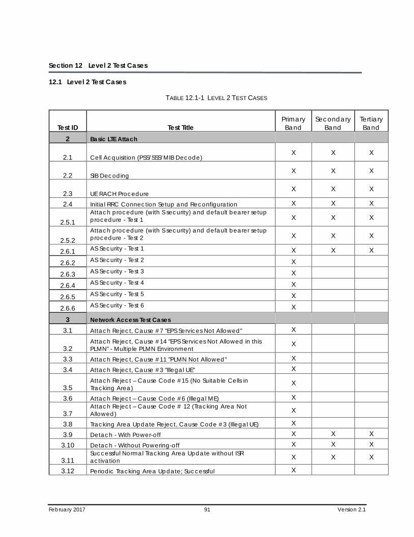
February 2017 91 Version 2.1
Section 12 Level 2 Test Cases
12.1 Level 2 Test Cases
TABLE 12.1-1 LEVEL 2 TEST CASES
Test ID Test Title Primary Band
Secondary Band
Tertiary Band
2 Basic LTE Attach
2.1 Cell Acquisition (PSS/SSS/MIB Decode) X X X
2.2 SIB Decoding X X X
2.3 UE RACH Procedure X X X
2.4 Initial RRC Connection Setup and Reconfiguration X X X
2.5.1 Attach procedure (with S security) and default bearer setup procedure - Test 1 X X X
2.5.2 Attach procedure (with S security) and default bearer setup procedure - Test 2 X X X
2.6.1 AS Security - Test 1 X X X
2.6.2 AS Security - Test 2 X
2.6.3 AS Security - Test 3 X
2.6.4 AS Security - Test 4 X
2.6.5 AS Security - Test 5 X
2.6.6 AS Security - Test 6 X
3 Network Access Test Cases 3.1 Attach Reject, Cause #7 "EPS Services Not Allowed" X
3.2 Attach Reject, Cause #14 "EPS Services Not Allowed in this PLMN" - Multiple PLMN Environment
X
3.3 Attach Reject, Cause #11 "PLMN Not Allowed" X 3.4 Attach Reject, Cause #3 "Illegal UE" X
3.5 Attach Reject – Cause Code #15 (No Suitable Cells in Tracking Area)
X
3.6 Attach Reject – Cause Code #6 (Illegal ME) X
3.7 Attach Reject – Cause Code # 12 (Tracking Area Not Allowed) X
3.8 Tracking Area Update Reject, Cause Code #3 (Illegal UE) X 3.9 Detach - With Power-off X X X
3.10 Detach - Without Powering-off X X X
3.11 Successful Normal Tracking Area Update without ISR activation X X X
3.12 Periodic Tracking Area Update; Successful X
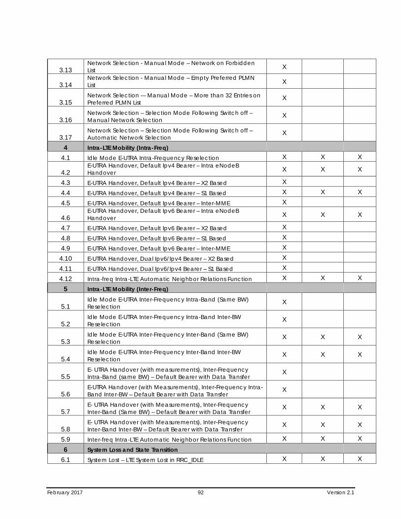
February 2017 92 Version 2.1
3.13 Network Selection - Manual Mode – Network on Forbidden List X
3.14 Network Selection - Manual Mode – Empty Preferred PLMN List X
3.15 Network Selection -– Manual Mode – More than 32 Entries on Preferred PLMN List
X
3.16 Network Selection – Selection Mode Following Switch off – Manual Network Selection
X
3.17 Network Selection – Selection Mode Following Switch off – Automatic Network Selection
X
4 Intra-LTE Mobility (Intra-Freq) 4.1 Idle Mode E-UTRA Intra-Frequency Reselection X X X
4.2 E-UTRA Handover, Default Ipv4 Bearer – Intra eNodeB Handover X X X
4.3 E-UTRA Handover, Default Ipv4 Bearer – X2 Based X 4.4 E-UTRA Handover, Default Ipv4 Bearer – S1 Based X X X 4.5 E-UTRA Handover, Default Ipv4 Bearer – Inter-MME X
4.6 E-UTRA Handover, Default Ipv6 Bearer – Intra eNodeB Handover X X X
4.7 E-UTRA Handover, Default Ipv6 Bearer – X2 Based X 4.8 E-UTRA Handover, Default Ipv6 Bearer – S1 Based X 4.9 E-UTRA Handover, Default Ipv6 Bearer – Inter-MME X
4.10 E-UTRA Handover, Dual Ipv6/Ipv4 Bearer – X2 Based X 4.11 E-UTRA Handover, Dual Ipv6/Ipv4 Bearer – S1 Based X 4.12 Intra-freq Intra-LTE Automatic Neighbor Relations Function X X X
5 Intra-LTE Mobility (Inter-Freq)
5.1 Idle Mode E-UTRA Inter-Frequency Intra-Band (Same BW) Reselection
X
5.2 Idle Mode E-UTRA Inter-Frequency Intra-Band Inter-BW Reselection
X
5.3 Idle Mode E-UTRA Inter-Frequency Inter-Band (Same BW) Reselection
X X X
5.4 Idle Mode E-UTRA Inter-Frequency Inter-Band Inter-BW Reselection
X X X
5.5 E- UTRA Handover (with measurements), Inter-Frequency Intra-Band (same BW) – Default Bearer with Data Transfer
X
5.6 E-UTRA Handover (with Measurements), Inter-Frequency Intra-Band Inter-BW – Default Bearer with Data Transfer
X
5.7 E- UTRA Handover (with Measurements), Inter-Frequency Inter-Band (Same BW) – Default Bearer with Data Transfer
X X X
5.8 E- UTRA Handover (with Measurements), Inter-Frequency Inter-Band Inter-BW – Default Bearer with Data Transfer
X X X
5.9 Inter-freq Intra-LTE Automatic Neighbor Relations Function X X X 6 System Loss and State Transition
6.1 System Lost – LTE System Lost in RRC_IDLE X X X
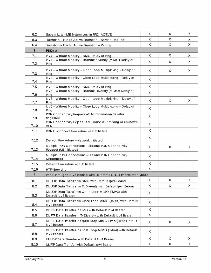
February 2017 93 Version 2.1
6.2 System Lost – LTE System Lost in RRC_ACTIVE X X X 6.3 Transition – Idle to Active Transition – Service Request X X X 6.4 Transition – Idle to Active Transition – Paging X X X 7 PS Data
7.1 Ipv4 – Without Mobility – SIMO Delay of Ping X X X
7.2 Ipv4 – Without Mobility – Transmit diversity (MIMO) Delay of Ping X X X
7.3 Ipv4 – Without Mobility – Open Loop Multiplexing – Delay of Ping
X X X
7.4 Ipv4 – Without Mobility – Close Loop Multiplexing – Delay of Ping X
7.5 Ipv6 – Without Mobility – SIMO Delay of Ping X
7.6 Ipv6 – Without Mobility – Transmit Diversity (MIMO) Delay of Ping X
7.7 Ipv6 – Without Mobility – Open Loop Multiplexing – Delay of Ping X X X
7.8 Ipv6 – Without Mobility – Close Loop Multiplexing – Delay of Ping X
7.9 PDN Connectivity Request –ESM Information transfer flag=TRUE X
7.10 PDN Connectivity Reject, ESM Cause #27 Missing or Unknown APN X
7.11 PDN Disconnect Procedure – UE Initiated X
7.12 Detach Procedure – Network Initiated X
7.13 Multiple PDN Connections – Second PDN Connectivity Request (UE Initiated)
X X X
7.14 Multiple PDN Connections – Second PDN Connectivity Disconnect
X
7.15 Detach Procedure – UE Initiated X 7.16 HTTP Browsing X
8 Peak Throughput Validation with Different PDSCH Transmission Mode 8.1 DL UDP Data Transfer in SIMO with Default Ipv4 Bearer X X X
8.2 DL UDP Data Transfer in Tx Diversity with Default Ipv4 Bearer X X X
8.3 DL UDP Data Transfer in Open Loop MIMO (TM=3) with Default Ipv4 Bearer
X
8.4 DL UDP Data Transfer in Close Loop MIMO (TM=4) with Default Ipv4 Bearer
X
8.5 DL FTP Data Transfer in SIMO with Default Ipv4 Bearer X 8.6 DL FTP Data Transfer in Tx Diversity with Default Ipv4 Bearer X
8.7 DL FTP Data Transfer in Open Loop MIMO (TM=3) with Default Ipv4 Bearer
X X X
8.8 DL FTP Data Transfer in Close Loop MIMO (TM=4) with Default Ipv4 Bearer
X
8.9 UL UDP Data Transfer with Default Ipv4 Bearer X X X 8.10 UL FTP Data Transfer with Default Ipv4 Bearer X X X
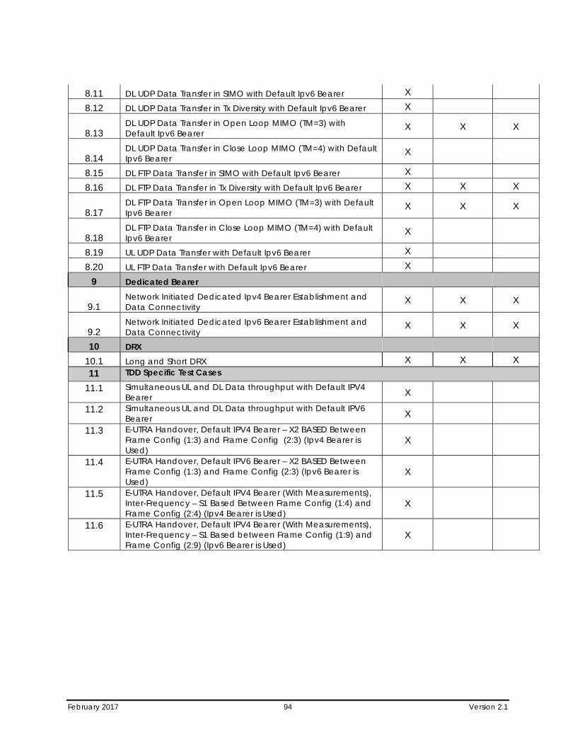
February 2017 94 Version 2.1
8.11 DL UDP Data Transfer in SIMO with Default Ipv6 Bearer X 8.12 DL UDP Data Transfer in Tx Diversity with Default Ipv6 Bearer X
8.13 DL UDP Data Transfer in Open Loop MIMO (TM=3) with Default Ipv6 Bearer
X X X
8.14 DL UDP Data Transfer in Close Loop MIMO (TM=4) with Default Ipv6 Bearer
X
8.15 DL FTP Data Transfer in SIMO with Default Ipv6 Bearer X 8.16 DL FTP Data Transfer in Tx Diversity with Default Ipv6 Bearer X X X
8.17 DL FTP Data Transfer in Open Loop MIMO (TM=3) with Default Ipv6 Bearer
X X X
8.18 DL FTP Data Transfer in Close Loop MIMO (TM=4) with Default Ipv6 Bearer
X
8.19 UL UDP Data Transfer with Default Ipv6 Bearer X 8.20 UL FTP Data Transfer with Default Ipv6 Bearer X
9 Dedicated Bearer
9.1 Network Initiated Dedicated Ipv4 Bearer Establishment and Data Connectivity
X X X
9.2 Network Initiated Dedicated Ipv6 Bearer Establishment and Data Connectivity
X X X
10 DRX 10.1 Long and Short DRX X X X 11 TDD Specific Test Cases
11.1 Simultaneous UL and DL Data throughput with Default IPV4 Bearer X
11.2 Simultaneous UL and DL Data throughput with Default IPV6 Bearer X
11.3 E-UTRA Handover, Default IPV4 Bearer – X2 BASED Between Frame Config (1:3) and Frame Config (2:3) (Ipv4 Bearer is Used)
X
11.4 E-UTRA Handover, Default IPV6 Bearer – X2 BASED Between Frame Config (1:3) and Frame Config (2:3) (Ipv6 Bearer is Used)
X
11.5 E-UTRA Handover, Default IPV4 Bearer (With Measurements), Inter-Frequency – S1 Based Between Frame Config (1:4) and Frame Config (2:4) (Ipv4 Bearer is Used)
X
11.6 E-UTRA Handover, Default IPV4 Bearer (With Measurements), Inter-Frequency – S1 Based between Frame Config (1:9) and Frame Config (2:9) (Ipv6 Bearer is Used)
X
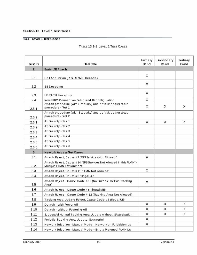
February 2017 95 Version 2.1
Section 13 Level 1 Test Cases
13.1 Level 1 Test Cases
TABLE 13.1-1 LEVEL 1 TEST CASES
Test ID Test Title Primary Band
Secondary Band
Tertiary Band
2 Basic LTE Attach
2.1 Cell Acquisition (PSS/SSS/MIB Decode) X
2.2 SIB Decoding X
2.3 UE RACH Procedure X
2.4 Initial RRC Connection Setup and Reconfiguration X
2.5.1 Attach procedure (with S security) and default bearer setup procedure - Test 1 X X X
2.5.2 Attach procedure (with S security) and default bearer setup procedure - Test 2
2.6.1 AS Security - Test 1 X X X 2.6.2 AS Security - Test 2 2.6.3 AS Security - Test 3 2.6.4 AS Security - Test 4 2.6.5 AS Security - Test 5 2.6.6 AS Security - Test 6
3 Network Access Test Cases 3.1 Attach Reject, Cause #7 "EPS Services Not Allowed" X
3.2 Attach Reject, Cause #14 "EPS Services Not Allowed in this PLMN" - Multiple PLMN Environment
3.3 Attach Reject, Cause #11 "PLMN Not Allowed" X 3.4 Attach Reject, Cause #3 "Illegal UE"
3.5 Attach Reject – Cause Code #15 (No Suitable Cells in Tracking Area)
X
3.6 Attach Reject – Cause Code #6 (Illegal ME) 3.7 Attach Reject – Cause Code # 12 (Tracking Area Not Allowed) 3.8 Tracking Area Update Reject, Cause Code #3 (Illegal UE) 3.9 Detach - With Power-off X X X
3.10 Detach - Without Powering-off X X X 3.11 Successful Normal Tracking Area Update without ISR activation X X X 3.12 Periodic Tracking Area Update; Successful X 3.13 Network Selection - Manual Mode – Network on Forbidden List X 3.14 Network Selection - Manual Mode – Empty Preferred PLMN List
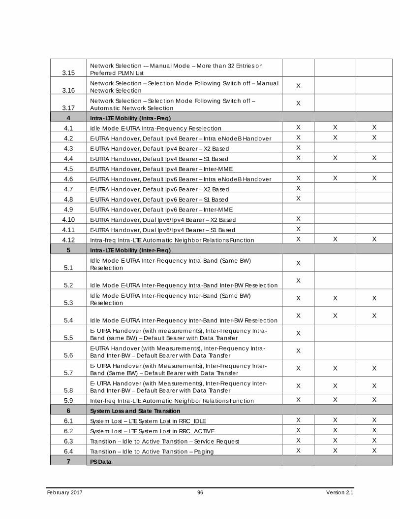
February 2017 96 Version 2.1
3.15 Network Selection -– Manual Mode – More than 32 Entries on Preferred PLMN List
3.16 Network Selection – Selection Mode Following Switch off – Manual Network Selection
X
3.17 Network Selection – Selection Mode Following Switch off – Automatic Network Selection
X
4 Intra-LTE Mobility (Intra-Freq) 4.1 Idle Mode E-UTRA Intra-Frequency Reselection X X X 4.2 E-UTRA Handover, Default Ipv4 Bearer – Intra eNodeB Handover X X X 4.3 E-UTRA Handover, Default Ipv4 Bearer – X2 Based X 4.4 E-UTRA Handover, Default Ipv4 Bearer – S1 Based X X X 4.5 E-UTRA Handover, Default Ipv4 Bearer – Inter-MME 4.6 E-UTRA Handover, Default Ipv6 Bearer – Intra eNodeB Handover X X X 4.7 E-UTRA Handover, Default Ipv6 Bearer – X2 Based X 4.8 E-UTRA Handover, Default Ipv6 Bearer – S1 Based X 4.9 E-UTRA Handover, Default Ipv6 Bearer – Inter-MME
4.10 E-UTRA Handover, Dual Ipv6/Ipv4 Bearer – X2 Based X 4.11 E-UTRA Handover, Dual Ipv6/Ipv4 Bearer – S1 Based X 4.12 Intra-freq Intra-LTE Automatic Neighbor Relations Function X X X
5 Intra-LTE Mobility (Inter-Freq)
5.1 Idle Mode E-UTRA Inter-Frequency Intra-Band (Same BW) Reselection
X
5.2 Idle Mode E-UTRA Inter-Frequency Intra-Band Inter-BW Reselection X
5.3 Idle Mode E-UTRA Inter-Frequency Inter-Band (Same BW) Reselection
X X X
5.4 Idle Mode E-UTRA Inter-Frequency Inter-Band Inter-BW Reselection X X X
5.5 E- UTRA Handover (with measurements), Inter-Frequency Intra-Band (same BW) – Default Bearer with Data Transfer
X
5.6 E-UTRA Handover (with Measurements), Inter-Frequency Intra-Band Inter-BW – Default Bearer with Data Transfer
X
5.7 E- UTRA Handover (with Measurements), Inter-Frequency Inter-Band (Same BW) – Default Bearer with Data Transfer
X X X
5.8 E- UTRA Handover (with Measurements), Inter-Frequency Inter-Band Inter-BW – Default Bearer with Data Transfer
X X X
5.9 Inter-freq Intra-LTE Automatic Neighbor Relations Function X X X 6 System Loss and State Transition
6.1 System Lost – LTE System Lost in RRC_IDLE X X X 6.2 System Lost – LTE System Lost in RRC_ACTIVE X X X 6.3 Transition – Idle to Active Transition – Service Request X X X 6.4 Transition – Idle to Active Transition – Paging X X X 7 PS Data
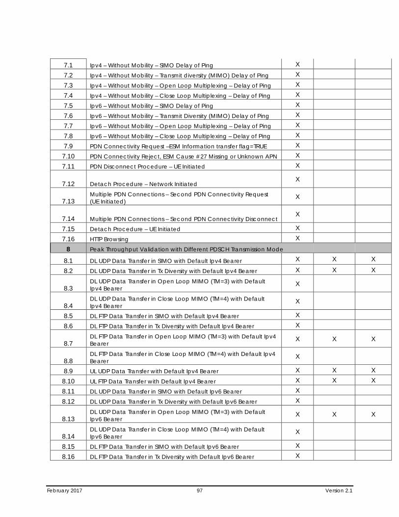
February 2017 97 Version 2.1
7.1 Ipv4 – Without Mobility – SIMO Delay of Ping X 7.2 Ipv4 – Without Mobility – Transmit diversity (MIMO) Delay of Ping X 7.3 Ipv4 – Without Mobility – Open Loop Multiplexing – Delay of Ping X 7.4 Ipv4 – Without Mobility – Close Loop Multiplexing – Delay of Ping X 7.5 Ipv6 – Without Mobility – SIMO Delay of Ping X 7.6 Ipv6 – Without Mobility – Transmit Diversity (MIMO) Delay of Ping X 7.7 Ipv6 – Without Mobility – Open Loop Multiplexing – Delay of Ping X 7.8 Ipv6 – Without Mobility – Close Loop Multiplexing – Delay of Ping X 7.9 PDN Connectivity Request –ESM Information transfer flag=TRUE X
7.10 PDN Connectivity Reject, ESM Cause #27 Missing or Unknown APN X 7.11 PDN Disconnect Procedure – UE Initiated X
7.12 Detach Procedure – Network Initiated X
7.13 Multiple PDN Connections – Second PDN Connectivity Request (UE Initiated)
X
7.14 Multiple PDN Connections – Second PDN Connectivity Disconnect X
7.15 Detach Procedure – UE Initiated X 7.16 HTTP Browsing X
8 Peak Throughput Validation with Different PDSCH Transmission Mode 8.1 DL UDP Data Transfer in SIMO with Default Ipv4 Bearer X X X
8.2 DL UDP Data Transfer in Tx Diversity with Default Ipv4 Bearer X X X
8.3 DL UDP Data Transfer in Open Loop MIMO (TM=3) with Default Ipv4 Bearer
X
8.4 DL UDP Data Transfer in Close Loop MIMO (TM=4) with Default Ipv4 Bearer
X
8.5 DL FTP Data Transfer in SIMO with Default Ipv4 Bearer X 8.6 DL FTP Data Transfer in Tx Diversity with Default Ipv4 Bearer X
8.7 DL FTP Data Transfer in Open Loop MIMO (TM=3) with Default Ipv4 Bearer
X X X
8.8 DL FTP Data Transfer in Close Loop MIMO (TM=4) with Default Ipv4 Bearer
X
8.9 UL UDP Data Transfer with Default Ipv4 Bearer X X X 8.10 UL FTP Data Transfer with Default Ipv4 Bearer X X X 8.11 DL UDP Data Transfer in SIMO with Default Ipv6 Bearer X 8.12 DL UDP Data Transfer in Tx Diversity with Default Ipv6 Bearer X
8.13 DL UDP Data Transfer in Open Loop MIMO (TM=3) with Default Ipv6 Bearer
X X X
8.14 DL UDP Data Transfer in Close Loop MIMO (TM=4) with Default Ipv6 Bearer
X
8.15 DL FTP Data Transfer in SIMO with Default Ipv6 Bearer X 8.16 DL FTP Data Transfer in Tx Diversity with Default Ipv6 Bearer X
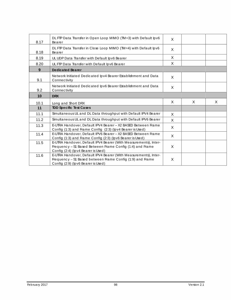
February 2017 98 Version 2.1
8.17 DL FTP Data Transfer in Open Loop MIMO (TM=3) with Default Ipv6 Bearer
X
8.18 DL FTP Data Transfer in Close Loop MIMO (TM=4) with Default Ipv6 Bearer
X
8.19 UL UDP Data Transfer with Default Ipv6 Bearer X 8.20 UL FTP Data Transfer with Default Ipv6 Bearer X
9 Dedicated Bearer
9.1 Network Initiated Dedicated Ipv4 Bearer Establishment and Data Connectivity
X
9.2 Network Initiated Dedicated Ipv6 Bearer Establishment and Data Connectivity
X
10 DRX
10.1 Long and Short DRX X X X 11 TDD Specific Test Cases
11.1 Simultaneous UL and DL Data throughput with Default IPV4 Bearer X 11.2 Simultaneous UL and DL Data throughput with Default IPV6 Bearer X 11.3 E-UTRA Handover, Default IPV4 Bearer – X2 BASED Between Frame
Config (1:3) and Frame Config (2:3) (Ipv4 Bearer is Used) X
11.4 E-UTRA Handover, Default IPV6 Bearer – X2 BASED Between Frame Config (1:3) and Frame Config (2:3) (Ipv6 Bearer is Used) X
11.5 E-UTRA Handover, Default IPV4 Bearer (With Measurements), Inter-Frequency – S1 Based Between Frame Config (1:4) and Frame Config (2:4) (Ipv4 Bearer is Used)
X
11.6 E-UTRA Handover, Default IPV4 Bearer (With Measurements), Inter-Frequency – S1 Based between Frame Config (1:9) and Frame Config (2:9) (Ipv6 Bearer is Used)
X
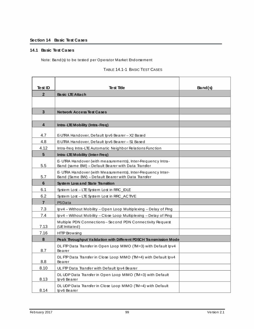
February 2017 99 Version 2.1
Section 14 Basic Test Cases
14.1 Basic Test Cases
Note: Band(s) to be tested per Operator Market Endorsement
TABLE 14.1-1 BASIC TEST CASES
Test ID Test Title Band(s) 2 Basic LTE Attach
3 Network Access Test Cases
4 Intra-LTE Mobility (Intra-Freq)
4.7 E-UTRA Handover, Default Ipv6 Bearer – X2 Based
4.8 E-UTRA Handover, Default Ipv6 Bearer – S1 Based 4.12 Intra-freq Intra-LTE Automatic Neighbor Relations Function
5 Intra-LTE Mobility (Inter-Freq)
5.5 E- UTRA Handover (with measurements), Inter-Frequency Intra-Band (same BW) – Default Bearer with Data Transfer
5.7 E- UTRA Handover (with Measurements), Inter-Frequency Inter-Band (Same BW) – Default Bearer with Data Transfer
6 System Loss and State Transition 6.1 System Lost – LTE System Lost in RRC_IDLE 6.2 System Lost – LTE System Lost in RRC_ACTIVE 7 PS Data
7.3 Ipv4 – Without Mobility – Open Loop Multiplexing – Delay of Ping 7.4 Ipv4 – Without Mobility – Close Loop Multiplexing – Delay of Ping
7.13 Multiple PDN Connections – Second PDN Connectivity Request (UE Initiated)
7.16 HTTP Browsing 8 Peak Throughput Validation with Different PDSCH Transmission Mode
8.7 DL FTP Data Transfer in Open Loop MIMO (TM=3) with Default Ipv4 Bearer
8.8 DL FTP Data Transfer in Close Loop MIMO (TM=4) with Default Ipv4 Bearer
8.10 UL FTP Data Transfer with Default Ipv4 Bearer
8.13 DL UDP Data Transfer in Open Loop MIMO (TM=3) with Default Ipv6 Bearer
8.14 DL UDP Data Transfer in Close Loop MIMO (TM=4) with Default Ipv6 Bearer
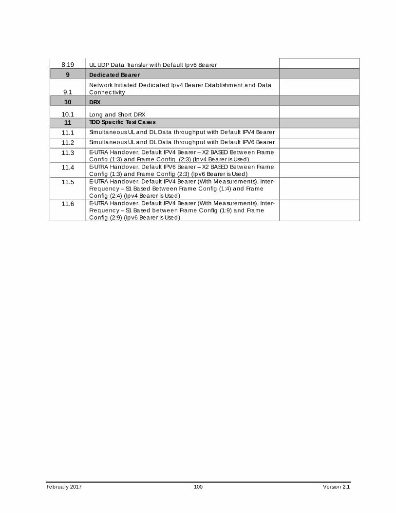
February 2017 100 Version 2.1
8.19 UL UDP Data Transfer with Default Ipv6 Bearer 9 Dedicated Bearer
9.1 Network Initiated Dedicated Ipv4 Bearer Establishment and Data Connectivity
10 DRX
10.1 Long and Short DRX 11 TDD Specific Test Cases
11.1 Simultaneous UL and DL Data throughput with Default IPV4 Bearer 11.2 Simultaneous UL and DL Data throughput with Default IPV6 Bearer 11.3 E-UTRA Handover, Default IPV4 Bearer – X2 BASED Between Frame
Config (1:3) and Frame Config (2:3) (Ipv4 Bearer is Used)
11.4 E-UTRA Handover, Default IPV6 Bearer – X2 BASED Between Frame Config (1:3) and Frame Config (2:3) (Ipv6 Bearer is Used)
11.5 E-UTRA Handover, Default IPV4 Bearer (With Measurements), Inter-Frequency – S1 Based Between Frame Config (1:4) and Frame Config (2:4) (Ipv4 Bearer is Used)
11.6 E-UTRA Handover, Default IPV4 Bearer (With Measurements), Inter-Frequency – S1 Based between Frame Config (1:9) and Frame Config (2:9) (Ipv6 Bearer is Used)
February 2017 101 Version 2.1
Appendix A Device Checklist and UE Information Summary
A.1 Checklist Document
Complete the attached checklist.
Device Checklist R1.doc
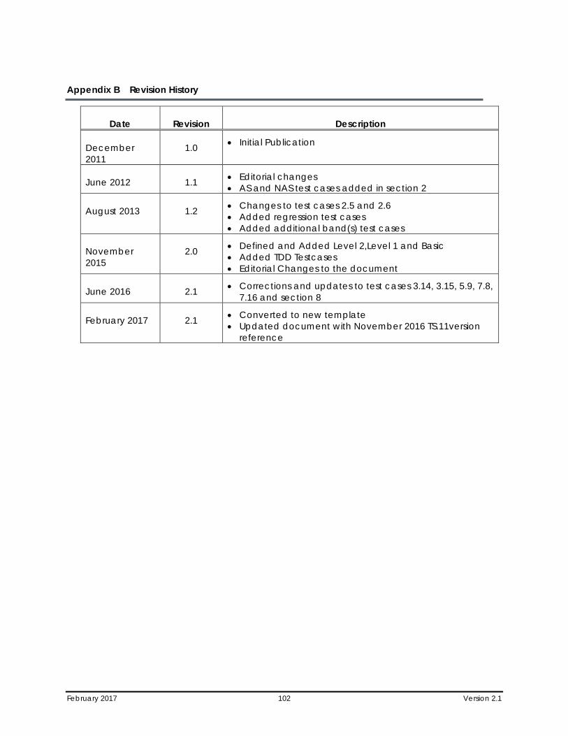
February 2017 102 Version 2.1
Appendix B Revision History
Date Revision Description
December 2011
1.0 • Initial Publication
June 2012 1.1 • Editorial changes • AS and NAS test cases added in section 2
August 2013 1.2 • Changes to test cases 2.5 and 2.6 • Added regression test cases • Added additional band(s) test cases
November 2015
2.0 • Defined and Added Level 2,Level 1 and Basic • Added TDD Testcases • Editorial Changes to the document
June 2016 2.1 • Corrections and updates to test cases 3.14, 3.15, 5.9, 7.8, 7.16 and section 8
February 2017 2.1 • Converted to new template • Updated document with November 2016 TS.11version
reference