Interoperability of microfluidic components -...
36
Interoperability of microfluidic components (status discussions June 2015) Henne van Heeren enablingMNT [email protected]
Transcript of Interoperability of microfluidic components -...

Interoperability of microfluidic components(status discussions June 2015)
Henne van Heeren
enablingMNT

Ongoing standardization discussions
• Chip sizes• Microfluidic interconnections:
– Chip to tube– Micropump / microsensor to tube – (Bio)sensor to chip– Combining with electrical or optical connections
• Classes of applications• Qualification of / tests for microfluidic components / systems• Flow control• Sample preparation• The “White Box”; one instrument / many different specific
disposables for different suppliers
Henne van Heeren, enablingMNTMicrofluidic Consortium, Paris, November
2015,
201/06/2015

Introduction standards
01/06/2015 3Henne van Heeren
enablingMNT

• Real operability needs standards or at least industry wide supported design rules.
• “Markets make standards, not committees”
• Therefore identify:
– the barriers and drivers for interoperability and standards,
– accepted (de facto) standards,
– technology trends,
– dominant players and their products.
01/06/2015 4Henne van HeerenenablingMNT

Barriers & Drivers for standards in microfluidics
Barriers:
• Market position of companies dominant in the market or are expecting to achieve such dominance.
• Investment in current products might become worthless.
• Diversity in the existing products already on the market.
• Lack of uniformity in our vocabulary.
• Existing standards in established industries.
Drivers:
• Health care: to enable diversity in testing, there are hundreds of specific tests needed, but the user wants to limit the number of instruments in the lab.
• Analytical instruments / processing equipment / R&D: to enable the selection of the best components and the ability to compare / qualify those components and the systems.
• Plug & play microfluidics.
01/06/2015 5Henne van HeerenenablingMNT
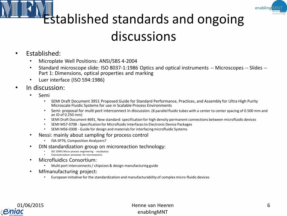
Established standards and ongoing discussions
• Established:• Microplate Well Positions: ANSI/SBS 4-2004• Standard microscope slide: ISO 8037-1:1986 Optics and optical instruments -- Microscopes -- Slides --
Part 1: Dimensions, optical properties and marking• Luer interface (ISO 594:1986)
• In discussion:• Semi
• SEMI Draft Document 3951 Proposed Guide for Standard Performance, Practices, and Assembly for Ultra High Purity Microscale Fluidic Systems for use in Scalable Process Environments
• Semi: proposal for multi port interconnect in discussion. (8 parallel fluidic tubes with a center to center spacing of 0.500 mm and an ID of 0.250 mm)
• SEMI Draft Document 4691, New standard: specification for high density permanent connections between microfluidic devices• SEMI MS7-0708 - Specification for Microfluidic Interfaces to Electronic Device Packages• SEMI MS6-0308 - Guide for design and materials for interfacing microfluidic Systems
• Nessi: mainly about sampling for process control• ISA-SP76, Composition Analyzers?
• DIN standardization group on microreaction technology: • ISO 10991 Micro process engineering - vocabulary• Characterization processes for microreactors.
• Microfluidics Consortium: • Multi port interconnects / chipsizes & design manufacturing guide
• Mfmanufacturing project: • European initiative for the standardization and manufacturability of complex micro-fluidic devices
01/06/2015 6Henne van HeerenenablingMNT

VDMA
01/06/2015 7Henne van HeerenenablingMNT
• VDMA has proposed a standard “Einheitsblatt” for micro fluidic technologies. Mainly for chemical process technologies. The VDMA 66305 defines the interfaces between so-called Match-X building blocks developed by Fraunhofer (IZM and IPA), both geometric as well as functional interfaces are described.
• Producers of Match-X building blocks that follow the VDMA-66305 standard, make the building block interoperable between other building blocks produced by other parties.
• 3.2.2 Fluidische Schnittstelle............................................................................ 73
• 3.2.2.1 Grundlagen und Erläuterungen zu den Definitionen der
• fluidtechnischen Schnittstelle .............................................................. 73
• 3.2.2.2 Verbindung zwischen fluidtechnischen Bausteinen und
• Montagetoleranzen.............................................................................. 74
• 3.2.2.3 Funktionale Definition der fluidtechnischen Schnittstelle..................... 77
• 3.2.2.4 Charakterisierung der Bausteine......................................................... 80
• 3.2.2.5 Messvorschrift für die Charakterisierung der fluidtechnischen
• Schnittstellen (vorläufig)...................................................................... 82
• 3.2.2.6 Beschreibung der Schnittstellenparameter.......................................... 82
• 3.2.2.7 Schnittstellenbeschreibung (Zeichnungen).......................................... 83

De facto standards for microfluidic designers
microscopy slide format microtiter plate format, layouts with
96, 384 or 1536 wells.
01/06/2015 8Henne van HeerenenablingMNT
Luer (ISO 594:1986)

SEMI MS7-0708: Specification for microfluidic interfaces to electronic device packages
Exploded 3-D View of EFIC Package
EFIC Fluidic Routing Card & Adapters
Functional Description of Assembled PartsRepublished with permission from Semiconductor Equipment
and Materials International (SEMI) 2012
01/06/2015 9Henne van HeerenenablingMNT

01/06/2015 10Henne van HeerenenablingMNT
NeSSI generation III systems:
microanalytical devices such as lab on
chip for process and water control.

Standardization activities in Germany
01/06/2015 11Henne van HeerenenablingMNT

De facto standard in fittings (for instance chromatography)
• Fittings:
– low pressure fluid transfer: thread ¼-28; flat bottom configuration
– high pressure fluid transfer: 10-32: coned configuration of port
• Tubing: 1.6 and 3.2 mm
01/06/2015 12Henne van HeerenenablingMNT

Where are we heading to as an industry?
01/06/2015 13Henne van HeerenenablingMNT

Direct sensing:
benchtop, < less then 1
hr, trained staff needed
With compact sample
treatment module:
handheld, <10 min,
process operators
Online
Automatic In
line & less then
1 sec
InlineOffline
Microfluidic based:
labinstrument, < 24
hr, expert staff
neededIn package
In the
package
2010 2015 2020 2025 2030
pg/ml
ng/ml
Sen
sor
sen
siti
vity
A vision on pathogen
detection the dairy industry
Roadmap for food diagnostics
01/06/2015 14Henne van HeerenenablingMNT

Integration: a key driver for smaller and faster diagnostic devices.
• Drivers:– Need for small sample sizes.
– Ease of use / robustness.
– Need for low cost disposables.
– Short time to measurement result.
• Challenges:
– Microfluidics doesn’t scale as easy as electronics (or even as mechanics) & electrons are electrons, but in microfluidics……………!
– Combining electronic, mechanical, fluidic and optical components or structures.
– Technology and business environment are immature.
01/06/2015 15Henne van HeerenenablingMNT

Always integrate microfluidics?
PoC third world
PoC (home) PoC (other) Central Lab Research
Acceptable time to result
Seconds to minutes
Seconds to minutes
< 6 minutes Up till half an hour
Up till several hours
Cost of instruments
Up to a few 100’s of $
Up to a few k$ Up to a few k$ Up to 100’s of k$
Up to a few M$
Staff Untrained Untrained Semi trained Trained Highly specialized
Cost of disposables
< 0.5 $ Preferable < 1 $
Preferable <3 $
Up to 10’s of $ Less relevant
Number of tests running
in parallel
1 1 1-10 Typical 10 -20 Less relevant, but flexibility
needed
Level of integration to be expected
Very high Very high High low Very low
01/06/2015 16Henne van HeerenenablingMNT

Identified integration concepts:
• The whole process from input sample to result (detected electrically or optically):– Chip: all microfluidic functions in one chip.
• on the market: glass, polymer, silicon chip.
• In development: paper, roll to roll manufactures films etc..
– “CD”: centrifugal driven microfluidic flow
– Card: microfluidic plate with additional components like a biochip mounted on top of the plate, the fluidic does not leave the microfluidic plate.
– Cartridge: the fluid is transferred from one component to another in a plane or in a 3D configuration.
– Not integrated: connections by tubing and wires.
01/06/2015 17Henne van HeerenenablingMNT

Technology trends in microfluidics
1. Chips suppliers are becoming component suppliers.
2. Well array testing is developing into more complex testing more akin to real life situations.
3. Digital microfluidics is seen as a way to miniaturize well array testing further.
4. More efficient and faster sample preparation units (PCR in a few minutes).
5. The industry is looking for technologies that don’t need labeling, i.e. biomarker specific sensors.
6. The industry is looking for technologies that don’t need time consuming PCR, i.e. hyper sensitive sensors.
7. Plug and play microfluidic instruments, cartridges, chip holders, connectors etc. are emerging.
01/06/2015 18Henne van HeerenenablingMNT

Agreed specifications
Chips and multiport connectors
01/06/2015 19Henne van HeerenenablingMNT

Microtiterplate
Microscope slide
15*4515*3015*15
75
127.76
25
85.4
8
01/06/2015 20Henne van HeerenenablingMNT
Double Microscope slide
50
84
54
Credit Card

Tolerance on chip dimensions
01/06/2015 21Henne van HeerenenablingMNT
We have defined an asymmetrical chips tolerance for
limiting oversize chips which will not fit in holders and
connectors:
Maximum / desired oversize is + 0.05 mm
Maximum undersize is - 0.15 mm
Preferred undersize is - 0.05 mm

Connection
Chipsize
Material
Design guide for chip layout & connections
Microfluidics
Polymer
Microtiterplate
127.76 * 85.48 mm
Miniluer
Microscope slide
75*25 mm
Miniluer
Glass
Microscope slide
75*25 mm
Clamped
45*45; 45*15; 30*30; 30*15 ;
15*15 mm
Clamped
From MF5 design guide for microfluidics
01/06/2015 22Henne van HeerenenablingMNT

Port pitches for microfluidic interconnections
Port pitch in mm. (logarithmic scale)
9 4.5 3 2.25 1.5 0.75
Clamped
Fully integrated?
Single port
connectors: chip
to tube
Multiple port
connectors: chip
to tube
Luer Miniluer
Multiple ports:
chip to adapter?
X(In discussion)
01/06/2015 23Henne van Heeren, enablingMNTMicrofluidic Consortium, Paris, November 2015,
Top connectors Top and/or edge connector
X
X(Not yet defined)

Connections to top of the chip(multiport) 1
01/06/2015 24Henne van HeerenenablingMNT
3
3
p p p D
Reference Point
Center of first hole
is at (3 mm,3 mm)
from reference point
3mm
3
p p p p p pDReference Point
Pitch is n*1.5 mm from
center to center
on the x axis.
Pitches are : 1.5
mm or multiples of
that
3
3
p p p D
Reference Point
Row pitch is n*1.5 mm
from center to center
on the y axis.
Always keep a distance of 3 mm to
sides of the chip

Connections to top of the chip(multiport) 2
01/06/2015 25Henne van HeerenenablingMNT
3
3
p p p D
1 2 3 4
A
B
C
Port nomenclatures : A1, A3 and C4.
On a 1,5mm Fluidic port grid.
Hole diameters are not standardized
however there is a minimum and
maximum recommended diameter which
is:
1.5 mm pitch 0.4 < D < 0.7
3.0 mm pitch 0.4 < D < 2.0
4.5 mm pitch 0.4 < D < 3.5

Summary Table of all the guideline dimensions and tolerances
01/06/2015 26Henne van HeerenenablingMNT
Parameter Nominalvalue
Minimalvalue
Maximalvalue
Tolerance
Reference point : left chip corner 0 mm
Distance of the first hole from the reference point (3 mm,3mm) (corner edge to hole center)
(3,3mm) +/- 0.15 mm
Minimal distance of any hole from any side of the chip 3mm
Distance between holes or Port pitch (center to center)from ref. point
n*1.5 mm 1.5 mm +/- 0.15 mm
Rows are parallel to the chip’s x axis at a distance fromref. point of n*1.5
n*1.5 1.5 mm +/- 0.15 mm
Hole diameter for 1.5 mm grid 0.4 mm 0,7 mm
Hole diameter for 3 mm grid 0.4 mm 2.0 mm
Hole diameter for 4.5 mm grid 0.4 mm 3.5 mm
Total Chip Thickness 1mm 0.85 mm 1.15 mm +/- 0.15 mmTotal Chip Thickness 1.8 mm 1.65 mm 1.95 mm +/- 0.15 mmTotal Chip Thickness 2 mm 1.80 mm 2.20 mm +/- 0.2 mmTotal Chip Thickness 4mm 3.60 mm 4.40 mm +/- 0.4 mmTight Tolerance of outer chip dimension (desired) +/- 0.05 mm
Lower Tolerance of outer chip dimension (when tighttolerance not achievable)
+ 0.05 / - 0.15mm

Layouts (1)
01/06/2015 27Henne van HeerenenablingMNT
port array 4x4
15x15 mm
port array 9x4
30x15 mm
port array 14x4
45x15 mm
60x15 mm port array 19x4
x
y yport array 24x7
75x25 mm
port array 24x15
75x50 mm
x
y

Layouts (2)
01/06/2015 28Henne van HeerenenablingMNT
port array 27x17
84x54 mm
x
y

On going discussions
01/06/2015 29Henne van HeerenenablingMNT

Sensor interface
01/06/2015 30Henne van HeerenenablingMNT
A
B
C
D
1 432
Fluidic I/O
Electrical connections (optional)

Edge connector
3 3
d1
d2

Microfluidic device classification proposed
Classes Minimum
temperature
(°C)
Maximum
Temperature
(°C)
Maximum
pressure
(bar)
A 4 50 2
B 0 75 2
C 0 100 2
D 4 50 7
E 0 100 7
F 4 50 30
01/06/2015 32Henne van HeerenenablingMNT
. Microfluidic device classification proposed

Qualification tests for microfluidic components and devices
• For getting true standard tests, the first steps would be the definition of the basic (minimal) requirements that should fulfill the microfluidic component/system in each application.
• Taking clear this basic requirements, it is possible to start thinking about what kind of tests (the simplest possible) can be performed to ensure those requirements.
• E.g. for an application it is defined that the microfluidic component have to support temperatures of -15ºC, so you can bring the component under nitrogen bath. So, you can check that your component supports such temperatures, even the time that can support the temperature.
Henne van HeerenenablingMNT

01/06/2015 Henne van Heeren, enablingMNT
34

Discussion to be continued
See www.mf-manufacturing.eu
Reactions to:
01/06/2015 35Henne van HeerenenablingMNT

Acknowledgements• Ali Tinzali, Gottfried Reiter, Harald Kraushaar
(Sony DADC)
• Ronny van ‘t Oever, Marko Blom (Micronit)
• Mark Giligan, Andrew Lovatt (Dolomite)
• Marco Bianchessi, Roberto Brioschi (ST Microelectronics)
• Peter Hewkins (CfBI)
• Mark Tondra (Diagnostics Biosensors)
• Holger Becker (MFCS)
• Richard Bijlard (Invenios)
• Thomas Dietrich (IVAM)
• Twan Korthorst (PhoeniX)
• Paul Wright (DIBA)
• Thomas Henkel (IPHT)
• Joost Lotters (Bronkhorst)
• Gerald Kreindl (EV Group)
• Thomas Hessler (Axetris)
• Mark Crockett (Memsmart)
• Nicolas Szita (University College London)
• Peter van Stiphout (Cytocentrics)
• Ray Filteau (CMC Microsystems)
• Vincent Spiering (Qmicro)
• Alexios Tzannis (IMTag)
• Gary Ng Sum Huan (SIMTech Microfluidics Foundry)
• Daniel Mark (IMTEK)
• Juan G. Santiago (Stanford University)
• Malcolm Wilkinson (TFI)
• Thomas Hessler (Axetris)
• Mario Castaño-Álvarez (Micrux)
• Gabor Szirbik (Thalesnano)
• Francois Leblanc (Fluigent)
• Pu Chen (Stanford University)
• And many others
01/06/2015 36Henne van HeerenenablingMNT


![Optical fiber LPG biosensor integrated microfluidic chip ......components (e.g. microfluidic mixers) to achieve the lab-on-a-chip analysis system [9]. Recently, it was demonstrated](https://static.fdocuments.net/doc/165x107/5f6551e7fabe321b8e0167ea/optical-fiber-lpg-biosensor-integrated-microfluidic-chip-components-eg.jpg)