Internet Protokolle II - net.in.tum.de
55
Thomas Fuhrmann Network Architectures Computer Science Department Technical University Munich Internet Protokolle II Lecture 5 R o u t i n g i n W i re les s A d - h o c N et wo rk s P a r t II
Transcript of Internet Protokolle II - net.in.tum.de

Thomas Fuhrmann
Network ArchitecturesComputer Science Department
Technical University Munich
Internet Protokolle II
Lecture 5
Routing in Wireless Ad-hoc NetworksPart II

Internet Protocols II Thomas Fuhrmann, Technical University Munich, Germany 2
Routing in Mobile Ad-Hoc Networks
• Extension of fixed wire protocols– Avoid ‚count to infinity‘ by exchanging richer state info– Damp updates to limit traffic
• Flooding to acquire state– Do not proactively maintain state– Search reactively for the requested destinations
• Limited flooding – Scopes and landmarks– Different areas have more or less detailed routing information
• Geographic routing– Exploit the fact that nodes have coordinates
• Virtual structures– Establish virtual ‚coordinates‘– Distribute routing info according to virtual coordinates

Internet Protocols II Thomas Fuhrmann, Technical University Munich, Germany 3
Global State Routing

Internet Protocols II Thomas Fuhrmann, Technical University Munich, Germany 4
Fisheye State Routing
Nodes have link info about all
other nodes, but info is less up-to-date the farther
the node.
Frequentupdates
Updates less and lessfrequently propagated

Internet Protocols II Thomas Fuhrmann, Technical University Munich, Germany 5
Global State & Fisheye State Routing
• Normally, link state routing would flood the network as soon as a link change was detected.– Topology changes are announced asap– Short fluctuations cause much traffic
• Global state routing exchanges info with direct neighbors, only.– Multiple topology changes accumulated and sent within one
message– Damping of short fluctuations– Sub-optimal routing because not all nodes have up-to-date
information– BTW, needs sequence numbers to avoid loops
• Fisheye state routing– Different intervals for sending updates (more often for closer nodes)– Same routing performance as GSR, but less update traffic (the
farther the destination, the less accurate information needed)

Internet Protocols II Thomas Fuhrmann, Technical University Munich, Germany 6
Ad-hoc On Demand Vector Routing
R
G
I‘m ‚R‘ and I needa route to ‚G‘.
‚R‘ needs a route to ‚G‘I‘m ‚G‘

Internet Protocols II Thomas Fuhrmann, Technical University Munich, Germany 7
Ad-hoc On Demand Vector Routing
R
G
Build up state along the path / reverse path*
* Reverse path is defined by the nodes that were first to sent the request for the respective destination.

Internet Protocols II Thomas Fuhrmann, Technical University Munich, Germany 8
Ad-hoc On Demand Vector Routing
R
G

Internet Protocols II Thomas Fuhrmann, Technical University Munich, Germany 9
AODV – Summary
• Receive route request?– Cache destination & sender of
request– If already cache, do nothing.– Otherwise, if not destination, re-
broadcast the request.– Otherwise, send route reply to
sender of request.• Receive route reply?
– Cache destination & sender of reply
– Forward reply to cached sender.• Use timeout to tear down the path.
• Reactive routing• Low processing demand,• But still high bandwidth demand
– if many nodes active, i.e. sending, receiving, or both
– nodes are mobile• Potentially high memory demand
(e.g. if timeout wrongly chosen)
Basic Operation Properties

Internet Protocols II Thomas Fuhrmann, Technical University Munich, Germany 10
Geographic Routing
Source
Destination
• All nodes know their geographic coordinates.
• Each node checks its neighbors‘coordinates.
• Packet is forwarded to node closest to destination.
Geographic routing can achieve near-to-optimal routes without (large) routing tables and without (signfigicant) control traffic.

Internet Protocols II Thomas Fuhrmann, Technical University Munich, Germany 11
Problems with Geographic Routing
Source Destination
Dead end
There is a path around the obstacle (red nodes), but greedy geographic routing leads into a
dead end (blue node).
Geographic routing can lead into dead ends, especially in presence of obstacles.

Internet Protocols II Thomas Fuhrmann, Technical University Munich, Germany 12
Greedy Perimeter Stateless Routing
• Use geographic routing (=greedy mode) until you get stuck in dead end.
• Enter your node ID into the packet, ‚turn around‘ and switch to perimeter mode.
• Forward to the right-most node until ‘obstacle bypassed’.
Source Destination

Internet Protocols II Thomas Fuhrmann, Technical University Munich, Germany 13
GPSR: Greedy and Perimeter Mode
Source
D
• Source has several neighbor, for example A and B. It prefers A because A is closer to D than B.
• The intersection of • the region reachable from A, and • the region that is closer to D than A
is empty. Thus switch to perimeter mode.
• Going back from A to S takes the ‘right-most’ edge.
• Node C is closer to D than A (where we switched to perimeter mode). Thus switch back to greedy mode.
A
B
C

Internet Protocols II Thomas Fuhrmann, Technical University Munich, Germany 14
GPSR Needs Planar Graphs
• Right-hand rule is only guaranteed to tour the entire perimeter ifgraph is planar.
• Thus we need to planarize the graph for GPSR!

Internet Protocols II Thomas Fuhrmann, Technical University Munich, Germany 15
Graph Planarization
• The Gabriel graph is a subgraph of the Delaunay triangulation. It is obtained by ensuring that two points P and Q are connected iff the circle that has PQ as its diameter contains no other nodes.
• Relative neighborhood graph: … P and Q connected iff no other node in both the circles around P and Q.
u vw
?
RNG
u vw
?
GG

Internet Protocols II Thomas Fuhrmann, Technical University Munich, Germany 16
Planarized Graphs – Examples
Full Graph GG Subgraph RNG Subgraph
200 nodes, placed uniformly at random on 2000-by-2000-meter region; 250-meter radio range.
Source: Brad Karp, UCL Computer Science

Internet Protocols II Thomas Fuhrmann, Technical University Munich, Germany 17
Planarization and Obstacles
• Obstacles violate assumtions of GG and RNG planarization.• This can lead to disconnected graphs.• Solution: Mutual agreement of nodes before an edge is removed.• But: This does not guarantee planarization any more.

Internet Protocols II Thomas Fuhrmann, Technical University Munich, Germany 18
GPSR Summary
• GPSR requires all nodes to know their physical coordinates.– GPS or triangulation with RSSI, …– Location directory to look up destination coordinates
• The resulting graph must be planar– Planarization algorithm– Not guaranteed in presence of obstacles
• Then, switching between greedy and perimeter mode can reach destinations behind obstacles.
Internet Protocols II Thomas Fuhrmann, Technical University Munich, Germany 19
Grid Location Service

Internet Protocols II Thomas Fuhrmann, Technical University Munich, Germany 20
Ant Routing
• Use geographic routing, and• Record direction to source
while routing– If entry already present,
enhance it by raising its weight
– Entries’ weights decrease over time unless they are enhanced
• Use routing table entries if their weight is sufficiently high
Greedy routing isfine here!
Greedy routing isfine here!

Internet Protocols II Thomas Fuhrmann, Technical University Munich, Germany 21
Last Encounter Routing (1)
Intuitively, mobility diffusion exploits three salient features of the node mobility processes: locality, mixing, and homogeneity… Locality ensures that aged information is still useful… Mixing of node trajectories ensures that position information diffuses around this destination node…Homogeneity ensures that the location information spreads at least as fast as the destination moves.
M. Grossglauser and M. Vetterli. Locating Mobile Nodes with EASE : Learning Efficient Routes from Encounter Histories Alone. IEEE/ACM Transactions on Networking, June 2006, 14(3), p. 457- 469

Internet Protocols II Thomas Fuhrmann, Technical University Munich, Germany 22
Last Encounter Routing (2)
• Use expanding ring search to find a node that more recently encountered the destination node → improves AODV, DSR
• Use last encounter positions to employ GPSR

Internet Protocols II Thomas Fuhrmann, Technical University Munich, Germany 23
Volcano Routing
• Source generates„infinite“ packet stream
• Destination consumesall packets
• Each node routes packet to that neighbor thatstores least packets of that stream
• Very robust (multipath)• Packet loss (due to
packets getting stuck) isnormal
• Nodes need to storemany packets, on theorder of hop distance
Source
Destination

Internet Protocols II Thomas Fuhrmann, Technical University Munich, Germany 24
( )
Beacon Vector Routing (1)
Beacon A
Beacon B Beacon C
351( )
113
( )212
( )232
( )330

Internet Protocols II Thomas Fuhrmann, Technical University Munich, Germany 25
Beacon Vector Routing (2)
• Some nodes are elected as beacons.• Beacons regularly broadcast their ID.• When forwarding beacon messages,
nodes update the messages‘ hop count.
• Nodes collect beacon messages to form a vector containing the beacons‘hop count.
• When routing a packet to a given destination ID, nodes try to match the destination‘s beacon vector with their neighbors‘ beacon vectors.
• If beacon vectors are not unique, use local flooding and the destinations globally unique ID.
• Advantage– Proactive– Robust– Limited state
• Drawback– Beacon election
difficult– Potentially not unique– Beacons flood the
network

Internet Protocols II Thomas Fuhrmann, Technical University Munich, Germany 26
Wegewahlverfahren – Ein Überblick
Dijkstra Fluten
Kürzeste Pfade, aber sehr große Routing-Tabellen, falls keine hierarchische Netzwerkstruktur existiert!
Kürzeste Pfade, aber sehr viele Nachrichten, falls keine Einbettung in einen Vektorraum existiert!
Dijkstra FlutenKürzeste Pfade
???
Wenig Zustand
Wen
ig Na
chric
hten

Internet Protocols II Thomas Fuhrmann, Technical University Munich, Germany 27
Virtual Ring Routing / Scalable Source Routing
1717
3232
111313
1919
8888
3939
4242117
32 3942

Internet Protocols II Thomas Fuhrmann, Technical University Munich, Germany 28
Scalable Source Routing
11
1717
1313
8888
4242
Knoten 13 virtuell nicht so weit wie Knoten 17.
Knoten 88 jenseits des Ziels.
Knoten 17 ist die beste Wahl.
117
42
1388

Internet Protocols II Thomas Fuhrmann, Technical University Munich, Germany 29
Scalable Source Routing
1717
3232
111313
1919
8888
4242117
42
19 Knoten 19 virtuell nicht so weit wie Knoten 32.
Knoten 32 ist die beste Wahl.
32

Internet Protocols II Thomas Fuhrmann, Technical University Munich, Germany 30
Scalable Source Routing
1717
3232
111313
1919
8888
4242117
3242
2727
27
Knoten 27 ist die einzige Option, würde aber virtuell
vom Ziel weg führen.
Jeder Knoten muss seinen Nachfolger im virtuellen Ring
kennen, d.h. eine SourceRoute dahin haben.
Strukturregel:

Internet Protocols II Thomas Fuhrmann, Technical University Munich, Germany 31
Scalable Source Routing
1717
3232
111313
1919
8888
3939
4242117
3942
32

Internet Protocols II Thomas Fuhrmann, Technical University Munich, Germany 32
Scalable Source Routing
1717
3232
111313
1919
8888
3939
4242117
3942
32
Fuhrmann, A Self-organizing Routing Scheme for Random Networks, Networking 2005.Caesar et al. Virtual Ring Routing: Network Routing Inspired by DHTs, SIGCOMM 2006.
Internet Protocols II Thomas Fuhrmann, Technical University Munich, Germany 33
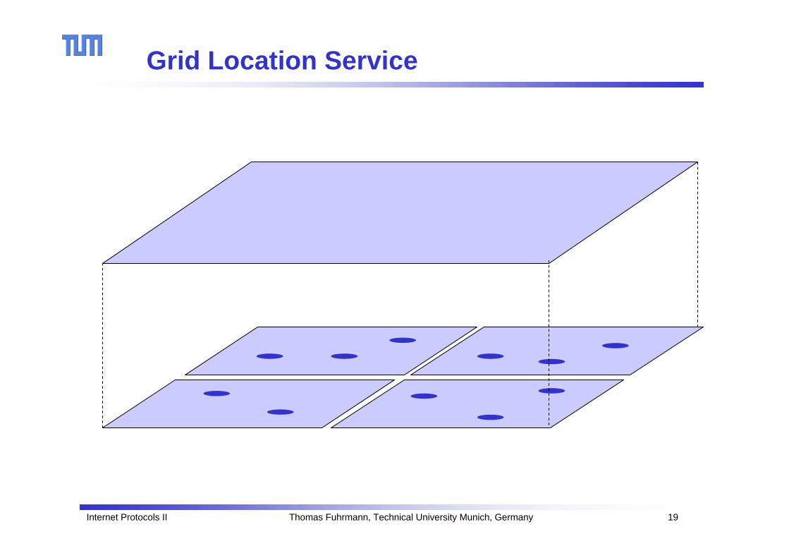
SSR – Selbstorganisation (1)
117
3242
1717
3232
111313
1919
8888
2727Theoretisch könnte eine Nachricht in viele Sackgassen laufen. In der Praxis sind Sackgassen selten:• Je größer die virtuelle Lücke, desto
höher die Wahrscheinlichkeit dass ein physisch naher Knoten die Lücke füllt.
• Knoten spezialisieren sich auf ihre virtuelle Nachbarschaft.

Internet Protocols II Thomas Fuhrmann, Technical University Munich, Germany 34
SSR – Selbstorganisation (2)
3232
4242
3939
3232
4242
3939
Nachbarschaftsempfehlungen(indirekte virtuelle Nachbarn)
Nachbarschaftsberichtigungen(direkte virtuelle Nachbarn)

Internet Protocols II Thomas Fuhrmann, Technical University Munich, Germany 35
Iterative Nachbarsuche (1)
29
1
51
42 5113
397 29 1
Sicht von Knoten 1:
NachbarBenachrichtigung
42
29
13
42 5113
397 29 1
Sicht von Knoten 13:
NachbarBenachrichtigung

Internet Protocols II Thomas Fuhrmann, Technical University Munich, Germany 36I 29
UpdateI29 I 29
I3 29I 29
I3 29
Iterative Nachbarsuche (2)
29
1
42 5113
397 29 1
NachbarBerichtigung Notify
Notify
Benachrichtigungen:
Knoten 29 kann die Inkonsistenz auflösen:
I3 29
Berichtigung:
13

Internet Protocols II Thomas Fuhrmann, Technical University Munich, Germany 37
Beweisskizze
42 5113
397 29 1
3 42 97291 5113
Physisch zusammen-hängender Graph
→Virtuell zusammen-hängender Graph

Internet Protocols II Thomas Fuhrmann, Technical University Munich, Germany 38
Beweisskizze
3 42 97291 5113
3 42 97291 5113
Die iterative Nachbarsuche führt zu einem global korrekt geordneten Ring aus Source Routen.
Internet Protocols II Thomas Fuhrmann, Technical University Munich, Germany 39
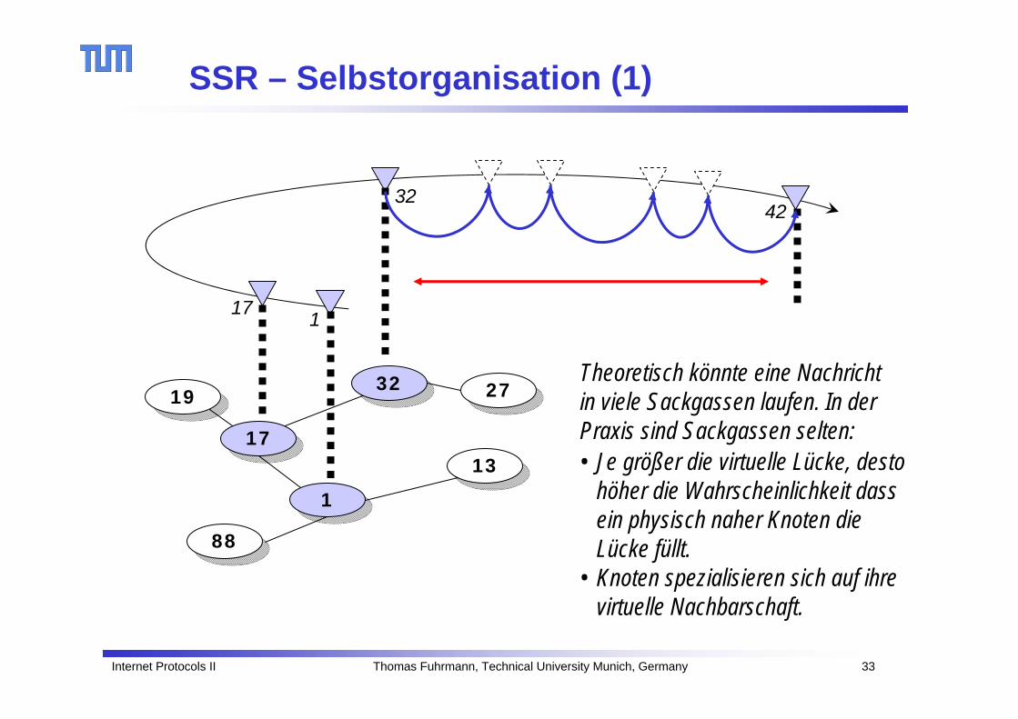
Ein Source Routen Cache
• Jeder Knoten speichert die Source Route zu seinem Nachfolger im virtuellen Ring (=Grundregel, vgl. Chord).
• Jeder Knoten speichert die Source Route zu seinem Vorgänger im virtuellen Ring (um ggf. eine Berichtigung zu senden).
• Weiterer Speicher wird als Cache genutzt, um Source Routen auf ‚least recently used‘Basis zu speichern. S
ourc
e R
oute
nC
ache
3
42 97
13
1
Fuhrmann, A Self-organizing Routing Scheme for Random Networks, Networking 2005.Fuhrmann, Scalable Routing for Networked Sensors and Actuators, SECON 2005.
29

Internet Protocols II Thomas Fuhrmann, Technical University Munich, Germany 40
Anwendung der Chord-Routing-Regeln
• Mit Hilfe der Source Routen im Cache wird nach den Regeln des nähengewahrenChord-Netzes geroutet:
• Bei einem ‚cache miss‘ wird die Anfrage zu dem Knoten weitergereicht, der– in Ringrichtung noch vor dem Ziel liegt,– physisch am nächsten und – virtuell am weitesten liegt.
42 5113
397 29 1
Beispiel: 13 → 51
13 42
13
29 42
3
42
3 13
97
29
1
51
3 97 29 1 51

Internet Protocols II Thomas Fuhrmann, Technical University Munich, Germany 41
Beispiel (cont.):
Im Cache sammeln sich allmählich gute Routen:
51
1
29
97
3
42
13
13
29 42
397 1
5113 29 1 51
13 42 3 97 29 1 51
134239729151
42 5113
397 29 1
51
1
29
97
342
13

Internet Protocols II Thomas Fuhrmann, Technical University Munich, Germany 42
Simulationsergebnisse (1) - Bootstrapping

Internet Protocols II Thomas Fuhrmann, Technical University Munich, Germany 43
Simulationsergebnisse (2) - Adressverteilung

Internet Protocols II Thomas Fuhrmann, Technical University Munich, Germany 44
Simulationsergebnisse (3) - AODV und DSR
Err
eich
bark
eit [
%]
Gesamtzahl KnotenHybrides MANET: 5% feste Knoten mit 10MBit/s, mobile Knoten mit 1m/s

Internet Protocols II Thomas Fuhrmann, Technical University Munich, Germany 45
Simulationsergebnisse (4) – Mobilität
Knotengeschwindigkeit [m/s]450 Knoten reines MANET
Err
eich
bark
eit [
%]

Internet Protocols II Thomas Fuhrmann, Technical University Munich, Germany 46
Simulationsergeb. (5) – Latenzverteilung
Delay [ms] 612 Knoten hybrides MANET
Err
eich
bark
eit [
%]

Internet Protocols II Thomas Fuhrmann, Technical University Munich, Germany 47
Simulationsergeb. (6) –Pfadlängenverteilung
Pfadlänge [Hops]800 Knoten hybrides MANET
Err
eich
bark
eit [
%]

Internet Protocols II Thomas Fuhrmann, Technical University Munich, Germany 48
Simulation Results (7) – Cluster Formation
Unit disk graph with uniformly random node positions (critical density).
Forwarding to physical neighbor according to routing rule leads to cluster formation.

Internet Protocols II Thomas Fuhrmann, Technical University Munich, Germany 49
Unzuverlässige und Mobile Geräte …
1717
3232
111313
1919
8888
3939
4242117
32 3942
Fuhrmann, Scalable Routing for Sensor Actuator Networks with Churn, SECON 2006.Fuhrmann et al. Scalable Routing for Hybrid MANETs, WONS 2007

Internet Protocols II Thomas Fuhrmann, Technical University Munich, Germany 50
Regel 1: Nur authentische Pfade cachen
1717
3232
111313
1919
8888
55 2323
5858
3939
9393
4242
2929
7777
5656
117
32 3942
1 17 32 5 23 58 39
Pfade aus weitergeleiteten Paketen dürfen gecached werden, aber nur der bereits durchlaufene Teil!

Internet Protocols II Thomas Fuhrmann, Technical University Munich, Germany 51
Regel 2: Zwischenknoten behalten
1717
3232
111313
1919
8888
55 2323
5858
3939
9393
4242
2929
7777
5656
117
32 3942
1 17 32 5 23 58 39
Zwischenknoten, die den Pfad im Paketkopf ergänzt haben, müssen im Paketkopf vermerkt bleiben, auch wenn sie auf einem Stummelpfad liegen!
58 23 93 42

Internet Protocols II Thomas Fuhrmann, Technical University Munich, Germany 52
Regel 3: Physische Nachbarn mitbenutzen …
1717
3232
111313
1919
8888
55 2323
5858
3939
9393
4242
2929
7777
5656
117
32 3942
Speichere die physischen Nachbarn deiner virtuellen Nachbarn. Falls alle Pfade zu einem virtuellen Nachbarn brechen, route zu einem physischen Nachbarn des virtuellen Nachbarn.
1 17 32 5 23 58 39 58 23 5 13 56 77

Internet Protocols II Thomas Fuhrmann, Technical University Munich, Germany 53
Simulationsergebnisse (2) – Node Churn
Hal
bwer
tsze
it [m
in]
Bestä
tigte
Pake
te [%
]
8000 Knoten, Knotenlebensdauer: Poisson-Prozess Zeit [min]
BestätigtLebensdauer

Internet Protocols II Thomas Fuhrmann, Technical University Munich, Germany 54
Vergleich SSR und VRR
• Source Routen• Zustand pro Knoten beschränkt• Große Paketköpfe durch Source Routen
(Reduktion auf lokale Interface IDs mögl.)• Konsistenz ohne Fluten (neues Verfahren,
früher ISPRP vgl. VRR Rep.)
• Tabellen mit Pfadeinträgen• Zustand pro Knoten potentiell
unbeschränkt• Kleine Paketköpfe• Konsistenz durch Fluten von
Repräsentanten IDs
1717
3232
111313
1919
8888
3939
4242117
32 39 42
1717
3232
111313
1919
8888
3939
4242117
32 39 42
Vergleichssimulationen zeigen leichten Vorteil von SSR solange Bandbreite nicht saturiert.Zustandbeschränkung bei SSR könnte für Realisierung in Hardware vorteilhaft sein.
Fuhrmann, SSR, Networking 2005 Caesar et al. , VRR, SIGCOMM 2006

Internet Protocols II Thomas Fuhrmann, Technical University Munich, Germany 55
Questions?
Thomas Fuhrmann
Department of InformaticsSelf-Organizing Systems Group
c/o I8 Network Architectures and ServicesTechnical University Munich, Germany