International outage coding system for nuclear power plants · IAEA-TECDOC-1393 International...
119
IAEA-TECDOC-1393 International outage coding system for nuclear power plants Results of a co-ordinated research project May 2004
Transcript of International outage coding system for nuclear power plants · IAEA-TECDOC-1393 International...

IAEA-TECDOC-1393
International outage coding system for nuclear power plants
Results of a co-ordinated research project
May 2004

The originating Section of this publication in the IAEA was:
Nuclear Power Engineering Section International Atomic Energy Agency
Wagramer Strasse 5 P.O. Box 100
A-1400 Vienna, Austria
INTERNATIONAL OUTAGE CODING SYSTEM FOR NUCLEAR POWER PLANTS IAEA, VIENNA, 2004 IAEA-TECDOC-1393ISBN 92–0–116003–8
ISSN 1011–4289 © IAEA, 2004
Printed by the IAEA in Austria May 2004

FOREWORD
A nuclear power plant is operated most safely and effectively, when it runs smoothly without unplanned power reductions or shutdowns. Therefore, any nuclear electricity production loss due to reactor unit power reduction or shutdown should be carefully tracked and evaluated. Based on such evaluation, causes of the energy losses could be analysed and eliminated.
Operating experience analysis is very important to identify trends and avoid precursors. Individual power plants or operating utilities may have limited operating experience; therefore, gathering international operating experience is necessary. To cope with the considerable amount of information gathered from all nuclear power plants throughout the world, it is necessary to codify the information facilitating the identification of causes of outages, systems or components failures, etc. Therefore, the IAEA established a sponsored Co-ordinated Research Project (CRP) on International Outage Coding System to develop a general, internationally applicable system of coding nuclear power plant outages providing worldwide nuclear utilities with a standardised tool for reporting outage information.
Taking into consideration the existing systems for coding nuclear power plant events (WANO, IAEA-Incident Reporting System (IRS) and IAEA power Reactor Information System (PRIS)), the PRIS outage coding system was chosen as the most adequate and basis for the project. A group of experts from utilities operating different types of nuclear power reactors worldwide was established. The group analysed the existing PRIS coding system in view of coding systems in use at the participating utilities and developed. a modified outage coding system. When implementing the modified coding system into PRIS, its performance indicators and their data elements were also revised.
This report summarises the results of the CRP and provides information for transformation of the historical outage data into the new coding system.
The IAEA wishes to express its gratitude to all experts participating in the project for their work and contributions as well as for the comments provided by their colleagues from nuclear industry worldwide. The IAEA officer responsible for this report was R. Spiegelberg-Planer from the Division of Nuclear Power.

EDITORIAL NOTE
The use of particular designations of countries or territories does not imply any judgement by the publisher, the IAEA, as to the legal status of such countries or territories, of their authorities and institutions or of the delimitation of their boundaries.
The mention of names of specific companies or products (whether or not indicated as registered) does not imply any intention to infringe proprietary rights, nor should it be construed as an endorsement or recommendation on the part of the IAEA.

CONTENTS
1. INTRODUCTION.............................................................................................................. 1
1.1. General ....................................................................................................................... 11.2. Background ................................................................................................................ 2 1.3. Definitions of used terms ........................................................................................... 2
2. GOVERNING PRINCIPLES OF THE CRP WORK ........................................................ 4
2.1. Continuity................................................................................................................... 4 2.2. Usefulness .................................................................................................................. 52.3. Consistency ................................................................................................................ 5 2.4. Completeness ............................................................................................................. 6
3. INTRODUCTION TO THE INTERNATIONAL OUTAGE CODING SYSTEM ........... 6
3.1. Coding system concept............................................................................................... 6 3.2. Outage time and energy loss specifications code ....................................................... 73.3. Outage type code ........................................................................................................ 7 3.4. Outage cause code .................................................................................................... 10
3.4.1. Direct cause.................................................................................................... 10 3.4.2. Systems involved ........................................................................................... 10
3.5. Descriptive part ........................................................................................................ 153.6. Complete form of the outage code ........................................................................... 15
4. IMPLEMENTATION OF THE CODING SYSTEM INTO PRIS .................................. 16
4.1. Modification of the existing pris coding system ..................................................... 16 4.1.1. Modifications of PRIS outage codes ............................................................. 16 4.1.2. Modifications of the PRIS reporting questionnaire form .............................. 26 4.1.3. Modifications of the PRIS reporting instructions .......................................... 26
4.2. Transformation of historical outage codes ............................................................... 27 4.2.1. Outage type code transformation ................................................................... 27 4.2.2. Outage cause code transformation ................................................................. 27 4.2.3. System code transformation........................................................................... 29
4.3. Modifications of PRIS performance indicators related to outages and energy losses...................................................................................................... 29 4.4. Revision of PRIS data elements ............................................................................... 30
4.4.1. Production data section.................................................................................. 30 4.4.2. Unavailability data section............................................................................. 31 4.4.3. Operating experience data ............................................................................. 33
4.5. Consequential activities............................................................................................ 34 4.5.1. Data acquisition and query softwares ............................................................ 34 4.5.2. Data storage ................................................................................................... 34 4.5.3. Other issues related to modification of PRIS................................................. 34
5. CONCLUSIONS AND FINDINGS................................................................................. 35
ANNEX 1: COMPARISON OF WANO, IRS AND PRIS CODING OF PLANT SYSTEMS .......................................................................................... 37
ANNEX 2: DESCRIPTION OF PRIS................................................................................. 47

ANNEX 3: PRIS QUESTIONNAIRE 1990 (PART 1 AND 2) .......................................... 50
ANNEX 4: PRIS QUESTIONNAIRE 2000 (PART 1 AND 2) .......................................... 60
ANNEX 5: DETAILED DESCRIPTIONS OF PRIS PERFORMANCE INDICATORS.................................................................... 80
ABBREVIATIONS................................................................................................................ 113
CONTRIBUTORS TO DRAFTING AND REVIEW............................................................ 115

1. INTRODUCTION
1.1. GENERAL
In the new environment of de-regulated energy market, when effective power production is prerequisite of competitiveness of each power producer, nuclear power plants have to face many challenges, such as: maintaining operational safety at the highest level, cost effectiveness, expressed through high availability to the grid and steady operation at the maximum available power, and good public acceptance.
Experience feedback is probably the most important factor that can help achieve uniform excellence in operating performance of nuclear power plants in the competitive electrical power industry. To maintain smooth plant operation and avoid unnecessary energy production losses, all incidents affecting power production should be tracked and analysed, causes of the significant events should be identified and appropriate corrective actions taken. Subsequent evaluation of trends in occurrence of similar events would provide for assessment of effectiveness of the implemented measures.
The experience obtained in each individual plant constitutes the most relevant source of information for improving its own performance. However experience on the level of the utility, country and world wide is also extremely valuable, because there are limitations to what can be learned from in-house experience. Most events which could conceivably occur, never do, others happen only infrequently, so building experience is a slow process, especially in handling unusual or unexpected situations. Therefore, the opportunity to learn from nuclear industry operating experience is beneficial to all.
Should the experience from production losses be effectively processed and used, it is necessary to have available a convenient system for brief description, classification and storage of this experience. An appropriate tool is a coding system that would allow storing the information in a smart database. But learning from the experience of others is admittedly difficult, if the information is not harmonised. Therefore, such system should be standardised and applicable to all types of reactors satisfying the needs of the broad set of nuclear power plant operators worldwide and allowing the experience to be shared internationally.
Therefore, the IAEA established a Co-ordinated Research Project (CRP) on International Nuclear Power Plant Outage Coding System with the objective of developing a general, standardised and internationally accepted system of coding outages (power reductions or shutdowns resulting in net electricity production losses). The coding should consider design specifications of various types of reactors and actual operating experience of nuclear operators worldwide. The intention is to provide nuclear utilities with a standardised tool for reporting outage information, so that it could be stored in a database enabling subsequent outage type and cause analysis.
This publication contains the results of the work done in the scope of this CRP. The introduction provides the background of the project including its historical context. It also includes definitions and terminology adopted. Section 2 discusses the basic governing principles. Section 3 explains the concept of the coding system and introduces its final outline. The implementation of the modified coding system into the existing PRIS system is described in Section 4. The associated PRIS (Reporting Questionnaires, Description of Performance Indicators) and other relevant documents are included in annexes.
1

1.2. BACKGROUND
The CRP was initiated upon recommendations of experts from IAEA member states participating in meetings related to PRIS held in 1996 and 1998. One of the first tasks of the CRP was to choose a suitable base for the outage coding system. Various international organisations have already developed coding systems associated with events at nuclear power plants. From the existing systems, the WANO, IAEA-IRS and IAEA-PRIS systems were evaluated due to their suitability for the purpose of developing an outage coding system.
The WANO and IRS coding systems are focused mainly on cause analysis of events concerning nuclear safety of nuclear power plants. They do not consider effects of the event on power production. These systems include some coded areas, which are not significant from power loss point of view, as they cover rather safety aspects of the event. However, the systems have fairly elaborated the coding of cause and plant systems involved in the events, so they are considered good source of information in this area.
On the other hand, the PRIS coding system is primarily focused on description of power outages causing losses in power production. PRIS has been the only authoritative system recording information on time and power losses due to outage since the commercial operation of nuclear power plants. However, in its existing form, it does not include all possible causes of outages based on international operating experience. The outage codes also do not specifically identify all types of outages, for example the reactor scram is not specifically included in the codes. The plant system coding is too general and does not include all specific plant systems for each reactor type that could be possibly involved in a plant outage.
Based on the review of the existing coding systems of nuclear power plant events (WANO, IAEA-IRS and IAEA PRIS), the PRIS outage coding system was chosen as basis for the project, because the code structure better corresponded with the power loss description requirements. Moreover, the system could be easily adapted to the current needs without losing the large amount of information previously stored in the database. The PRIS system was further developed using the other two coding systems (WANO and IAEA IRS) as reference for the development of outage cause codes and codes of systems involved. Because of the long history of PRIS outage coding system and the large amount of outage data collected over the past 30 years, continuity with the PRIS outage coding was maintained and the historical data could be also kept in the new system. The modified outage coding system was implemented in PRIS and tested by several nuclear power plants for its suitability.
Together with development of the outage coding system, also PRIS performance indicators were revised, because plant outages always affect plant performance. The current trends in WANO Performance indicators were followed and PRIS Performance Indicator data elements were modified to provide specific information of forced energy losses and unplanned outage extensions as well as of unplanned reactor scrams. The annexes present the results of this work.
1.3. DEFINITIONS OF USED TERMS
During development of the coding system, it was recognised that some terms widely used in the industry, which appear both in this report and in the coding system, may not be always understood in the same way. To ensure consistence in understanding, definitions of the most frequent terms, as accepted and adopted for the sole purpose of the coding system, are provided below.
2

Controlled Shutdown
The reactor unit shutdown is considered controlled if it was achieved by controlled reduction of reactor and turbine power at the standard rate as required by plant operating procedures.
Direct Outage Cause
Only direct outage causes are coded in this coding system. The direct cause is defined as an immediate action or condition that has directly resulted in the outage.
Energy Loss
It is the total energy expressed in megawatt-hours (electric) that was not delivered to the grid or other consumers1 due to the outage.
External Outage Cause
An outage cause is considered external, if it could not be controlled (prevented or influenced) by the plant management.
Full/Partial Outage
An outage is considered full if the actual unit output power was reduced to zero percent (unit disconnected from all off-site power supply lines). An outage is considered partial if the actual unit output power is lower than its reference value, but is greater than zero percent.
Planned/Unplanned Outage
An outage is considered planned, if it was scheduled at least four weeks in advance. An outage is considered unplanned, if it was not scheduled at least four weeks in advance.
Outage
For the coding purpose, the outage is defined as any status of a reactor unit, when its actual output power is lower than the reference unit power for a period of time, regardless of the cause of this condition. By this definition, the outage includes both power reduction and unit shutdown.
In the coding system, the term outage refers to actual unit output power rather than to reactor power. In other words, the outage is full whenever the unit is disconnected from all off-site power supply lines, while the reactor power may be still greater than zero.
Outage Duration
Outage duration is defined as the time of the outage from the beginning of the reporting period or the outage, whichever comes last, to the end of the reporting period or the outage, whichever comes first.
1 For non-electrical applications
3

The outage extension is defined as the unplanned portion of a planned outage, causing prolongation of the planned outage beyond its originally planned completion date. Outage extensions are always considered unplanned.
Reporting Period
In general, the reporting period is defined as the time, for which the outage data are reported. The reporting period currently recommended in PRIS is six months, but the data should be reported at least once a year.
Scram
The reactor scram is defined as a reactor shutdown achieved by rapid insertion of negative reactivity into the reactor core, which can be performed either manually or automatically.
Significant Outage
The outage is considered significant, if the loss in the energy production corresponds to at least 10 hours of continuous operation at the reference unit power, or if it was caused by an unplanned reactor scram (even if the unit had been shut down for less than 10 hours).
System Involved
The system involved is defined as the plant equipment directly causing the outage or the one being most significantly affected by the event initiating the outage.
Unavailability
For the purpose of the outage coding system, the unit unavailability is defined as the status when the plant is not able to operate at its reference power. This condition, which may be under or beyond plant management control, should only reflect lack of availability of the plant itself, regardless of energy demand, transmission grid condition or political situation in the country. It follows from the definition, that the term "outage" is more general and does not always imply unit unavailability. In other words, some outages may occur, even though the unit is fully available.
2. GOVERNING PRINCIPLES OF THE CRP WORK
2.1. CONTINUITY
PRIS was established 30 years ago with the purpose of providing information on electricity production of nuclear power plants world-wide. It contains more than 70,000 records of outages, which should be historically maintained. Therefore, any changes or adjustments should take into account the historical information available in the system.
The goal was to expand the existing outage coding system in those aspects, which did not attend the users' needs. The present PRIS outage codification system is ”system oriented”, and not ”equipment/component oriented". For continuity reasons, this principle was kept, assuring that no information is lost and there is no discontinuity with the historical data available.
4
Outage Extension
It is acknowledged that the information brought by the outage coding might not be sufficient for nuclear power plant management. For instance, reliability of plant system components cannot be calculated, as the coding includes only their systems or sub-system and not the component coding. It has been concluded by the CRP participants that an equipment reliability database is solely under the plant management responsibility in front of its different manufacturers and cannot be included in an international database with no commercial purposes.
The outage coding system clearly refers to a statistical (with ”codification” and figures) and not to an event approach (with descriptions and root cause analysis). It constitutes a first level tool for plant performance benchmarking. Nevertheless, it was also of interest to reinforce the link between statistics and events, so changes were made to get a more explicit outage description as a part of the outage codification file.
2.2. USEFULNESS
Although, there are many actors involved in the assessment of nuclear power plant performance, the major is the plant/utility management. They should have both the national and international experience feedback tools at their disposal. Therefore, improvements of the existing PRIS coding were proposed in the project to fully fulfil worldwide nuclear utility management's needs. The improvements should provide additional opportunities for adjusting or building the maintenance/operation strategy. Although most nuclear units operate in base-load mode in terms of electricity grid requirement, the outage coding is also adequate for other operational modes.
2.3. CONSISTENCY
One of the main issues considered during the project was consistency with other international organisations, mainly with existing documents issued by WANO and Eurelectric (former UNIPEDE) in this area. These organizations conducted consistent studies and made proposals for terminology, performance indicator definitions and experience feedback tools. Therefore the proposed modifications have taken into account:
• Terminology and performance indicators definitions as developed by Eurelectric and WANO (with a few exceptions).
• WANO codification for events. A transposition guide is provided in Annex 1.
• Adoption of the new WANO proposal of relaxing the ”four weeks in advance” rule for planned outage.
The CRP also avoided duplication of efforts to the maximum possible extent. The role of this outage coding system should be complementary to the other existing event coding systems in WANO, IAEA-IRS and other international organisations because of their different areas of interest.
5

2.4. COMPLETENESS
All reactor types, except prototypes and research reactors, have been taken into account to provide reporting basis for all utilities providing outage data to PRIS.
Although the outage coding system assumed the report of all outages, whatever the origin and the magnitude of the corresponding loss, the minimum level of reporting was established as follows:
• Significant outages with losses of more than 10 equivalent full outage hours. • Any unplanned (manual, automatic) reactor scrams • Unplanned extensions of planned outages.
To provide comprehensive information of plant performance and keep records of all energy losses, the coding also considers outages due to load following operations, when the plant was fully capable to operate at reference power..
Although the modified outage coding provides information on "system level", rather than "component level", important pieces of equipment such as reactor vessel, reactor coolant pumps, steam-generators were regarded as compact systems and therefore, included in the coding as separate systems.
3. INTRODUCTION TO THE INTERNATIONAL OUTAGE CODING SYSTEM
3.1. CODING SYSTEM CONCEPT
The outage coding is primarily focused on reporting power production losses. It is conceived as basis for plant performance analysis. Assuming nuclear power plants primarily run in base-load operation, it is appropriate to record all outages in power production, i.e. all events when the actual output power of the reactor unit was lower than the reference unit power. The intention of the coding is not only to describe various aspects of the outage itself, but also to cover all possible reasons of its occurrence, such as planned activities, poor performance, off-site effects and power delivery limitations.
Considering this primary objective, the coding includes only those aspects of the outage events that can be useful in analyses focused on elimination of unnecessary power losses. Safety aspects of the events, such as root causes, consequences and plant activities preceding the event are not coded. They are sufficiently covered by the WANO and IAEA-IRS coding systems.
The coding consists of three major codes. The first code identifies outage date and duration and amount of energy lost due to the outage. The second code, named Type Code, identifies the kind and extent of the outage and provides technical information about the outage. The third code, named Cause Code, covers the causes of the outage and the system that was significantly involved in the outage. To include supplementary information of the outage, a description field is also provided.
6
3.2. OUTAGE TIME AND ENERGY LOSS SPECIFICATION CODE
This code provides date of occurrence and duration of the outage. It also specifies energy loss due to the outage. The code consists of the following components:
Start Date
This field requires the format: “yyyy-mm-dd”, e.g. 2000-12-28 for 28 December 2000.
If no particular date can be specified, e.g. for continuous load following operation, the first day of the reporting period is considered the start date of the outage. The same rule applies if an outage extends from the previous reporting period.
Duration
In this field, the time of outage (within a reporting period) is entered in full clock hours, including the power decrease and power raise periods. The outage begins at the moment when power decrease starts. It ends as soon as the initial power level is again reached. If an hour fragment occurs in the measured outage duration, it should be rounded.
If part of the outage extends to the next reporting period, the corresponding outage duration is coded for each reporting period separately. For intermittent outages, e.g. due to load following operation, which may repeat irregularly during the reporting period, the total hours for the reporting period should be entered in this field.
Energy Loss (net) [(MW(e) h)]
Energy losses are calculated separately for each outage in the system. If several outages are concurrent for a period of time, energy loss for each outage is reported as if the unit was operated at the reference power at the beginning of the outage.
For intermittent outages (e.g. due to load following operation), the cumulative energy loss for the whole reporting period is entered in the field.
As all reactor scrams are considered in the coding system, also those scrams that occur after the last main generator is disconnected from the grid (causing no additional power reduction) are coded as outages. For these outages, no energy loss and duration data is entered in the code (the corresponding code fields should be left blank).
3.3. OUTAGE TYPE CODE
The outage type is coded by a three-character code describing several circumstances of outage occurrence. It can provide answers to questions like: Could the plant management prevent the outage? Was the outage planned? Was the unit disconnected from the grid? Was the unit power reduced in a controlled manner or was the outage due a reactor scram? Wasn't it just an extension of a planned outage?
The type coding should include one of the characters showed in Table1.
7

TABLE 1. TYPE CODE, FIRST CHARACTER
Code Description
P Planned outage due to causes under the plant management control (internal)
U Unplanned outage due to causes under the plant management control (internal)
X Outage due to causes beyond the plant management control (external)
The outage is considered planned (P), if it is scheduled at least four weeks in advance(generally at the time when the annual overhaul, refuelling or maintenance programme is established), and if the beginning of the unavailability period can be largely controlled and deferred by plant management. An outage is considered unplanned (U), if it has not been scheduled at least four weeks in advance. The “external” (X) outages may be also considered planned or unplanned. Although this aspect is not explicitly coded, adding the third character (see below) to the "external" outage code will imply the unplanned “external” outage.
For historical continuity reasons, the first character of the code combines two "levels" of outage type code. It simultaneously identifies, whether the outage could or could not be controlled by the plant management. At the same time it codifies, if the outage was planned or unplanned. For the "internal" outages, the planned and unplanned outages are explicitly coded, as they are more important for the coding purpose.
The codes P and U thus imply an outage due to causes under plant management control. Although the “external” outages, which are coded only X, may be also considered planned or unplanned, this aspect is not explicitly coded for this type of outage. However, adding the third character (see below) to the "external" outage code X would imply an unplanned“external” outage.
In general, any change in the planned outage start date is considered unplanned, unless it is announced at least four weeks in advance. If the start date is anticipated, the outage is considered unplanned until the originally scheduled start date. If the start date is postponed, the outage is still considered planned until the originally scheduled completion date. The unplanned portions of planned outages should be coded as separate outages.
Any extension of the planned outage beyond the original completion date is considered unplanned, unless it is announced at least four weeks in advance. The unplanned extension of outages is codified separately using a third character. The planned extensions of outages are considered a part of the planned outages and are not coded separately.
For example, if a unit is shut down due to an equipment failure shortly before the refueling outage, so that it cannot be restarted until the outage beginning, the plant management may decide to start the outage earlier. In such a case, the portion of the outage until the originally planned refueling start date should be reported as a separate unplanned outage caused by an equipment failure, while the rest of the outage would be coded as planned for annual maintenance and refueling. No outage extension would be reported provided the planned refueling outage was finished within the originally planned completion date.
8

TABLE 2. TYPE CODE, SECOND CHARACTER
Code Description
F Full outage
P Partial outage
The second character identifies whether some energy was still delivered by the unit during the outage. As the coding refers to outage unit power, the outage is considered full (F) whenever the unit is disconnected from the transmission grid (the main generator output breaker is opened) and from all other energy consumers (the off-site steam/hot water lines are isolated). In some cases, the outage may be considered full, even if the reactor remains at power. Table 2 presents codes for the second character.
An outage is considered full (F) if the actual unit output power has been reduced to zero percent (unit disconnected from all off-site power supply lines). An outage is considered partial (P) if the actual unit output power is lower than its reference value, but is greater than zero percent.
TABLE 3. TYPE CODE, THIRD CHARACTER (FOR UNPLANNED OUTAGES ONLY)
Code Description 1 Controlled shutdown or load reduction that could be deferred but had to be
performed earlier than four weeks after the cause occurred or before the next refueling outage, whatever comes first
2 Controlled shutdown or load reduction that had to be performed in the next 24 hours after the cause occurred
3 Outage extension
4 Reactor scram, automatic
5 Reactor scram, manual.
The third character codification (Table 3) describes special circumstances of the outage. It recognises, if the outage was achieved by controlled power reduction at normal operating rate or if it was due to an unplanned reactor scram. It also identifies extension of planned outage (X). Any reactor protection function reducing reactor power is considered controlled power reduction, unless it fully inserts into the core all the control elements (rods) designed to scram the reactor.
The third character should be assigned also to outages due to causes beyond plant management control ("external" outages), which can be considered unplanned (e.g. the causes coded J, M, N, R, T and U in the table provided below).
Using the above characters, the outage type code can have one of the following forms (planned scrams and planned extension of outages are not considered):
PF or PPUF1-5 or UP1-3XF or XP XF1-5 or XP1-3
9

3.4. OUTAGE CAUSE CODE
The outage cause code consists of two parts: the cause-code itself and the code of system involved.
3.4.1. Direct cause
The outage coding is focused on direct causes of outages. It does not look for root causes, which may have been in the background of the occurrence. Identify root causes is the purpose analytical coding systems, such as those within WANO or IAEA-IRS, which serve for in-depth analysis of all safety-related events.
The direct cause is understood here as the immediate initiatory action causing the outage. For example, if a minor equipment failure, as oil leak dropping on hot pipeline or short-circuit in a non-vital switchgear cabinet, resulted in extensive fire that directly caused an outage, the fire would be considered the direct cause of the outage.
If outages occur successively, they should be reported as separate outage due to different causes. For example, if the unit power was first reduced due to an equipment failure, but the unit subsequently tripped due to a human error when responding to the failure, these incidents should be reported as two separate outages caused by equipment failure and human factor respectively. Similarly, partial and full outage following immediately one upon the other, but having the same direct cause, must be reported separately.
For each outage code, only one direct cause should be selected from the below list:
Planned outages may be coded as B, C, D, E, F, G; unplanned outages may be coded A, H, L, P; "external" outages may be coded J, K, M, N, R, T and U. The cause coded S can apply to planned, unplanned and "external" outages.
3.4.2. Systems involved
Some outages can be caused by system failure. In other outages, systems can be significantly damaged due to malfunction during the outage or otherwise affected by the outage work. Such systems are coded as well. Therefore cause codes related to equipment (A), repair (D), testing (E), back-fitting (F, G), nuclear regulatory requirements (H), human actions (L), environmental conditions (N), fire (P), fuel management (S) and other (Z) should, whenever possible, be completed by the numerical code of the plant system involved.
The plant system code consists of four numerical characters, where the first two characters identify a general system group, while the other two characters identify a particular system from that group.
10
The system codification is based on comparison of the current PRIS coding with WANO, IRS coding systems and with plant specific coding systems. The system code is presented in Table 5.

TABLE 4. DIRECT CAUSES OF OUTAGES
Code2 Description
A Plant equipment failure B Refuelling without a maintenance C Inspection, maintenance or repair combined with refuelling D Inspection, maintenance or repair without refuellingE Testing of plant systems or componentsF Major back-fitting, refurbishment or upgrading activities with refuelling G Major back-fitting, refurbishment or upgrading activities without refuellingH Nuclear regulatory requirements J Grid failure or grid unavailability K Load-following (frequency control, reserve shutdown due to reduced energy
demand) L Human factor related M Governmental requirements or court decisions N Environmental conditions (flood, storm, lightning, lack of cooling water due
to dry weather, cooling water temperature limits etc.) P Fire R External restrictions on supply and services (lack of funds due to delayed
payments from customers, disputes in fuel industries, fuel-rationing, labour strike outside the plant3, spare part delivery problems etc.)
S Fuel management limitation (including high flux tilt, stretch out or coast-down operation)
T Offsite heat distribution system unavailability U Security and access control Z Others
In general, more systems are involved in the outage. Nevertheless, the system selected for coding should be that system which either directly caused the outage, was primarily involved, or was possibly most significantly affected by the outage.
If no particular system could be specified from the general system group, the general system code “xx.00” is selected. If a particular system was involved in the outage, but no suitable code was found in the list, then the “other” code ”xx.99” of the appropriate general system group should be used. If no system was involved/affected in the outage, the second to fifth characters in the outage cause code also be left blank.
2 The letters “I”, “O” and “Q” have been deliberately omitted to avoid confusing with digits “0” and “1” 3 Outages caused by plant personnel strikes should be coded “L” - Human factor related.
11

TABLE 5. PLANT SYSTEMS POSSIBLY INVOLVED IN THE OUTAGE
Code System Description
Nuclear Systems
11.00 Reactor and Accessories 11.01 Reactor vessel and main shielding (including penetrations and nozzles) 11.02 Reactor core (including fuel assemblies) 11.03 Reactor internals (including steam separators/dryers - BWR, graphite,
pressure tubes) 11.04 Auxiliary shielding and heat insulation 11.05 Moderator and auxiliaries (PHWR) 11.06 Annulus gas system (PHWR/RBMK) 11.99 None of the above systems
12.00 Reactor I&C Systems12.01 Control and safety rods (including drives and special power supply) 12.02 Neutron monitoring (in-core and ex-core) 12.03 Reactor instrumentation (except neutron) 12.04 Reactor control system 12.05 Reactor protection system 12.06 Process computer 12.07 Reactor recirculation control (BWR) 12.99 None of the above systems
13.00 Reactor Auxiliary Systems 13.01 Primary coolant treatment and clean-up system 13.02 Chemical and volume control system 13.03 Residual heat removal system (including heat exchangers) 13.04 Component cooling system 13.05 Gaseous, liquid and solid radwaste treatment systems 13.06 Nuclear building ventilation and containment inerting system 13.05 Nuclear building ventilation and containment inerting system 13.06 Gaseous, liquid and solid radwaste treatment systems 13.07 Nuclear equipment venting and drainage system (including room floor
drainage)13.08 Borated or refuelling water storage system 13.09 CO2 injection and storage system (GCR) 13.10 Sodium heating system (FBR) 13.11 Primary pump oil system (including RCP or make-up pump oil) 13.12 D2O leakage collection and dryer system (PHWR) 13.13 Essential auxiliary systems (GCR)
13.99 None of the above systems
14.00 Safety Systems 14.01 Emergency core cooling systems (including accumulators and core spray
system) 14.02 High pressure safety injection and emergency poisoning system 14.03 Auxiliary and emergency feedwater system 14.04 Containment spray system (active)
12

Code System Description 14.05 Containment pressure suppression system (passive) 14.06 Containment isolation system (isolation valves, doors, locks and penetrations)14.07 Containment structures 14.08 Fire protection system 14.99 None of the above systems
15.00 Reactor Cooling Systems 15.01 Reactor coolant pumps/blowers and drives 15.02 Reactor coolant piping (including associated valves) 15.03 Reactor coolant safety and relief valves (including relief tank) 15.04 Reactor coolant pressure control system 15.05 Main steam piping and isolation valves (BWR) 15.99 None of the above systems
16.00 Steam generation systems 16.01 Steam generator (PWR), boiler (PHWR, AGR), steam drum vessel (RBMK,
BWR) 16.02 Steam generator blowdown system 16.03 Steam drum level control system (RBMK, BWR) 16.99 None of the above systems
17.00 Safety I&C Systems (excluding reactor I&C) 17.01 Engineered safeguard feature actuation system 17.02 Fire detection system 17.03 Containment isolation function 17.04 Main steam/feedwater isolation function 17.05 Main steam pressure emergency control system (turbine bypass and steam
dump valve control) 17.06 Failed fuel detection system (DN monitoring system for PHWR) 17.07 RCS integrity monitoring system (RBMK)
17.99 None of the above systems
Fuel and Refuelling Systems
21.00 Fuel Handling and Storage Facilities 21.01 On-power refuelling machine 21.02 Fuel transfer system 21.03 Storage facilities, including treatment plant and final loading and cask
handling facilities 21.99 None of the above systems
Secondary plant systems
31.00 Turbine and auxiliaries 31.01 Turbine 31.02 Moisture separator and reheater 31.03 Turbine control valves and stop valves 31.04 Main condenser (including vacuum system) 31.05 Turbine by-pass valves 31.06 Turbine auxiliaries (lubricating oil, gland steam, steam extraction)
13

Code System Description 31.07 Turbine control and protection system 31.99 None of the above systems
32.00 Feedwater and Main Steam System 32.01 Main steam piping and valves 32.02 Main steam safety and relief valves 32.03 Feedwater system (including feedwater tank, piping, pumps and heaters) 32.04 Condensate system (including condensate pumps, piping and heaters) 32.05 Condensate treatment system 32.99 None of the above systems
33.00 Circulating Water System 33.01 Circulating water system (pumps and piping/ducts excluding heat sink
system) 33.02 Cooling towers / heat sink system 33.03 Emergency ultimate heat sink system 33.99 None of the above systems
34.00 Miscellaneous Systems 34.01 Compressed air (essential and non-essential / high-pressure and low-pressure)34.02 Gas storage, supply and cleanup systems (nitrogen, hydrogen, carbon dioxide
etc.)34.03 Service water / process water supply system (including water treatment) 34.04 Demineralized water supply system (including water treatment) 34.05 Auxiliary steam supply system (including boilers and pressure control
equipment) 34.06 Non-nuclear area ventilation (including main control room) 34.07 Chilled water supply system 34.08 Chemical additive injection and makeup systems 34.09 Non-nuclear equipment venting and drainage system 34.10 Communication system 34.99 None of the above systems
35.00 All other I&C Systems 35.01 Plant process monitoring systems (excluding process computer) 35.02 Leak monitoring systems 35.03 Alarm annunciation system 35.04 Plant radiation monitoring system 35.05 Plant process control systems 35.99 None of the above systems
Electrical Systems
41.00 Main Generator Systems 41.01 Generator and exciter (including generator output breaker) 41.02 Sealing oil system 41.03 Rotor cooling gas system 41.04 Stator cooling water system 41.05 Main generator control and protection system 41.99 None of the above systems
14
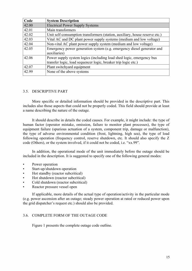
Code System Description 42.00 Electrical Power Supply Systems 42.01 Main transformers 42.02 Unit self-consumption transformers (station, auxiliary, house reserve etc.) 42.03 Vital AC and DC plant power supply systems (medium and low voltage) 42.04 Non-vital AC plant power supply system (medium and low voltage) 42.05 Emergency power generation system (e.g. emergency diesel generator and
auxiliaries)42.06 Power supply system logics (including load shed logic, emergency bus
transfer logic, load sequencer logic, breaker trip logic etc.) 42.07 Plant switchyard equipment 42.99 None of the above systems
3.5. DESCRIPTIVE PART
More specific or detailed information should be provided in the descriptive part. This includes also those aspects that could not be properly coded. This field should provide at least a name describing the nature of the outage.
It should describe in details the coded causes. For example, it might include: the type of human factor (operator mistake, omission, failure to monitor plant processes), the type of equipment failure (spurious actuation of a system, component trip, damage or malfunction), the type of adverse environmental condition (frost, lightning, high sea), the type of load following operation (frequency control, reserve shutdown, etc. It should also specify the Z code (Others), or the system involved, if it could not be coded, i.e. “xx.99”.
In addition, the operational mode of the unit immediately before the outage should be included in the description. It is suggested to specify one of the following general modes:
• Power operation • Start-up/shutdown operation • Hot standby (reactor subcritical)• Hot shutdown (reactor subcritical)• Cold shutdown (reactor subcritical)• Reactor pressure vessel open
If applicable, more details of the actual type of operation/activity in the particular mode (e.g. power ascension after an outage; steady power operation at rated or reduced power upon the grid dispatcher’s request etc.) should also be provided.
3.6. COMPLETE FORM OF THE OUTAGE CODE
Figure 1 presents the complete outage code outline.
15

Description of the outage (cause and mode):
FIG. 1. Complete outage coding.
4. IMPLEMENTATION OF THE CODING SYSTEM INTO PRIS
One of the follow-up tasks of the project was to incorporate the newly developed international outage coding system into the existing PRIS outage coding system. It resulted in modifications concerning both the PRIS Reporting Questionnaire for submitting the outage data and the PRIS Reporting Instruction providing guidance for the questionnaire completion. To keep the continuity of the modified PRIS coding system, all the historical data needs to be converted into the modified codes. Therefore, the data transformation concept was also discussed within the CRP. The implementation of the modified Outage Coding System into PRIS requires further modifications of the PRIS supporting software and training to familiarise the users with new coding principles and data reporting requirements. These consequential activities were also outlined in the CRP work.
Along with incorporating the international outage coding system into PRIS, the other kinds of the PRIS data (production data, availability data and operating experience data) were amended in the scope of the CRP work. This should ensure consistency with the outage data reporting and also with similar projects being in progress within IAEA (non-electrical applications) and the other international nuclear industry organisations, WANO or Eurelectric.
The modified PRIS coding should result in more detailed and complete information of individual outages. Consequently, a broader variety of statistical evaluations and analyses of plant and industry performance would be possible. The modified instructions should provide better guidance to data providers.
4.1. MODIFICATION OF THE EXISTING PRIS CODING SYSTEM
4.1.1. Modifications of PRIS outage codes
The date code component was replaced by start date to indicate that the first day of the outage should be reported. As elsewhere in the modified PRIS Coding, the year should be entered in the four-digit form. If no specific start date could be determined, the first day of the actual reporting period should be entered. The reporting period here means the period the questionnaire is submitted for.
Similar modification was performed in the duration code, where the “reference period” was replaced by “reporting period”. This should prevent confusing this field with the reference period used in the Section I - “Production Data” of the PRIS Questionnaire.
16
Start Date:[yyyymmdd]
Duration:[Hours]
Energy Loss (net): [MWe·h]
Type Code: Cause Code:
|_|_|_|_|_|_|_|_| |_|_|_|_| |_|_|_|_|_|_| |_|_|/|_| |_|/|_|_|.|_|_|

The term unavailable energy was changed to energy loss for consistency with the requirement to code all types of outages, including outages when the unit was fully available. If for example, the outage was due to grid failure or lack of energy demand, the unit was still available to operate at the reference power. So in fact, there was no energy unavailable, but there was a loss of energy production, which should be coded.
In the outage type coding, the third character providing codes for unplanned outages has been significantly modified. Instead of the original three categories of unplanned outages, five new categories have been introduced. Analysis of historical data have shown that the current codes “UF1”, “UP1”, “UF2” and “UP2” have occurred very rarely, thus they have little information value. The original three categories of unplanned outages coded “1”, “2” and “3” have been therefore reduced to two categories: (code 1) outages following a controlled power reduction due to causes allowing the shutdown/power reduction to be postponed and (code 2) outages following a controlled power reduction needing immediate action. In addition, codes for outage extension (code 3) and outages resulting from unplanned reactor scrams, both automatic (code 4) and manual (code 5) have been incorporated.
It was proposed to assign the third character also to the external outages that can be considered unplanned. The unplanned external outage may be due to grid failure, adverse environmental conditions or external restrictions on supplies and services. Such extended code of an external outage will provide more information for outage analysis, and will also imply the unplanned nature of the particular external outage.
Direct comparison of the current and new outage ‘type code’ is provided in Table 6.
For ‘cause coding’, the rule of coding direct cause was incorporated in the PRIS system. The original instruction to report the “main cause” was more general, and in a particular case, it might be difficult for the data providers to decide, which of the causes contributing to the outage should be considered “the main cause”. PRIS users should not confuse “direct cause” and “root cause”. The concept of “direct cause” is the same as in WANO event coding system.
Explanatory notes were included for coding the outage cause in case several direct causes had contributed to the outage or in case two or more outages followed immediately one after another, whether they had the same cause or not.
To enable the plants coding as many outage causes as possible, additional categories of direct causes of outages were added. The modification should cover a broader variety of conditions that may directly cause a plant outage. Consequently, the outage cause code will provide more specific information of the actual outage cause.
In accordance with the new concept of ‘cause coding’, the following modifications of the current codes have been made:
17

CurrentCode
Description New Code
Description
PF Planned full outage PF Planned full outage PP Planned partial outage PP Planned partial outage UF1 Unplanned full outage which could
be deferred beyond the following weekend
UF2 Unplanned full outage which could be deferred up to the following weekend
UF1 Unplanned controlled shutdown that could be deferred, but had to be performed earlier than in four weeks or before the next refuelling outage
UF2 Unplanned controlled shutdown that had to be performed immediately
UF3 Unplanned extension of full shutdown
UF4 Unplanned automatic scram
UF3 Unplanned full outage requiring immediate action
UF5 Unplanned manual scram UP1 Unplanned partial outage which
could be deferred beyond the following weekend
UP2 Unplanned partial outage which could be deferred up to the following weekend
UP1 Unplanned power reduction that could be deferred, but had to be performed earlier than in four weeks or before the next refuelling outage
UP2 Unplanned power reduction that had to be performed immediately
UP3 Unplanned partial outage requiring immediate action
UP3 Unplanned extension of power reduction
XF Planned full outage due to external reasons
XF1 Unplanned controlled shutdown due to external reasons that could be deferred, but had to be performed earlier than in four weeks or before the next refuelling outage
XF2 Unplanned controlled shutdown due to external reasons that had to be performed immediately
XF3 Unplanned extension of a shutdown due to external reasons
XF4 Unplanned automatic scram due to external reasons
XF Full outage due to external reasons
XF5 Unplanned manual scram due to external reasons
XP Partial outage due to external reasons
XP Planned partial outage due to external reasons
18
TABLE 6. COMPARISON OF CURRENT AND MODIFIED OUTAGE TYPE CODES

CurrentCode
Description New Code
Description
XP1 Unplanned power reduction due to external reasons that could be deferred, but had to be performed earlier than in four weeks or before the next refuelling outage
XP2 Unplanned power reduction due to external reasons that had to be performed immediately
XP3 Unplanned extension of power reduction due to external reasons
Code A – Equipment related was renamed to “plant equipment failure” to point out that only failures of plant equipment should be considered. This denomination also better reflects the requirement to report direct causes. Equipment failure” is more “direct” than “equipment related”). The note in parentheses has been deleted, because outages caused directly by equipment failure should be always coded “A”, no matter what “initiated” the equipment failure. Outages directly caused by grid failure should be coded “J”.
Code B – Human factor related was re-coded “L”. The training and procedures noted in parentheses were deleted, because they implied reporting root cause, which would be in contradiction to the concept of direct cause coding. The new cause - “Refuelling without a maintenance” was coded B.
Code F – New code for “Major back-fitting, refurbishment or upgrading activities with refuelling” was introduced
Code G – Fuel management limitations was re-coded “S”. Specifications of the cause in parentheses were extended by the high flux tilt, which means the high differences in neutron flux across the core preventing the reactor from reaching full power. The code G was assigned to “Major back-fitting, refurbishment or upgrading activities without refuelling”.
Code J – Grid unavailability was renamed to “Grid failure or grid unavailability” to indicate that this code should be used primarily for grid disturbances. The outages due to lack of energy demand should be coded K.
Code K – This code (meaning others) was assigned to “Load-following (frequency control, reserve shutdown due to reduced energy demand)”. The "other" causes were re-coded “Z”.
Code L – Governmental requirements or Court decisions was re-coded “M”
Comparison of the original ‘cause codes’ with the modified codes (including the new ones included in the system) is provided in Table 7. The letters “I”,“O” and “Q” were intentionally omitted to prevent confusing with the digits “1” and “0”.
19

TABLE 7. COMPARISON OF THE CURRENT AND MODIFIED OUTAGE CAUSE CODES
CurrentCode
Description New Code
Description
A Equipment related (including those initiated by grid)
A Plant equipment failure
B Human factor related (including training and procedures)
B Refuelling without a maintenance
C Planned inspection, maintenance and repair combined with refuelling
C Inspection, maintenance or repair combined with refuelling
D Planned inspection, maintenance and repair when not combined with refuelling
D Inspection, maintenance or repair without refuelling
E Testing of plant systems or components
E Testing of plant systems or components
F Major back-fitting, refurbishment or upgrading activities with refuelling
G Fuel management limitation (including stretch-out or coast-down operation
G Major back-fitting, refurbishment or upgrading activities without refuelling
H Nuclear regulatory requirements
H Nuclear regulatory requirements
J Grid unavailability J Grid failure or grid unavailability K Other K Load-following (frequency control,
reserve shutdown due to reduced energy demand)
L Governmental requirements or court decisions
L Human factor related
M Governmental requirements or Court decisions
N Environmental conditions (flood, storm, lightning, lack of cooling water due to dry weather, cooling water temperature limits etc.)
P Fire R External restrictions on supply and
services (lack of funds due to delayed payments from customers, disputes in fuel industries, fuel-rationing, labour strike outside the plant4, spare part delivery problems etc.)
S Fuel management limitation (including
4 Outages caused by plant personnel strikes should be coded “L”, Human factor related
20

CurrentCode
Description New Code
Description
high flux tilt, stretch out or coast-down operation)
T Offsite heat distribution system unavailability
U Security and access control Z Others
In the modified PRIS ‘Coding of systems involved’, the existing codes of general system groups were extended by specific codes of individual systems that might be included in each system group. Instead of the two-digit code as used in the current PRIS Coding System, four-digit codes were incorporated. The new codes were assigned to each system listed under the former general system codes. In addition, new systems were introduced to cover most of the equipment existing at various plants. Due to this modification, more specific information would be available about the system involved in a particular outage.
The modified PRIS coding retained the possibility to code the general system (code “xx.00”), if no single system could be specified from the general system group. The coding also provides a code for a particular system involved, that could not be found in the provided list. Using the code “xx.99” for such “other” subsystems has made the modified coding open for appending other system codes, if necessary at a later time.
When developing the new plant system coding, most of the original two-digit codes were maintained to keep continuity with the previous database. The“22” code was dismissed, because the Fuel Assembly originally coded “21” was included in the“11.02 - Reactor core” code. The Fuel Handling and Storage Facilities was re-coded “21.00”. The steam generator blowdown system, originally included in the“32” code, was appended to Steam Generation System and re-coded “16.02”. In addition, some system and system group names were modified according to the international outage coding. The modifications were made to either retain internal consistency of terminology or provide more general system description that might be appropriate to majority of plants. The comparison of current and modified coding of plant systems is provided in Table 8.
TABLE 8. COMPARISON OF THE CURRENT AND NEW CODES OF SYSTEMS INVOLVED IN AN OUTAGE
Current Coding New Coding Nuclear Systems
11 Reactor and Accessories 11.00 Reactor and Accessories Reactor vessel and main shielding Reactor vessel penetrations
11.01 Reactor vessel and main shielding (including penetrations and nozzles)
Reactor internals 11.03 Reactor internals (including steam separators/dryers - BWR, graphite, pressure tubes)
Auxiliary shielding and heat insulation 11.04 Auxiliary shielding and heat insulation
11.05 Moderator and auxiliaries (PHWR) 11.06 Annulus gas system (PHWR/RBMK) 11.99 None of the above systems
21

Current Coding New Coding 12 Reactor I&C Systems 12.00 Reactor I&C SystemsControl and safety rods and drives 12.01 Control and safety rods (including
drives and special power supply) Neutron monitoring (in-core plus external) 12.02 Neutron monitoring (in-core and ex-
core)Reactor instrumentation (except neutron) 12.03 Reactor instrumentation (except
neutron)Reactor control logic 12.04 Reactor control system Reactor protection logic 12.05 Reactor protection system Process computer 12.06 Process computer 12.07 Reactor recirculation control (BWR) 12.99 None of the above systems 13 Operating Auxiliaries 13.00 Reactor Auxiliary Systems Primary coolant treatment and clean-up system (BWR and GCR)
13.01 Primary coolant treatment and clean-up system
Chemical and volume control system (PWR)
13.02 Chemical and volume control system
Residual heat removal system (including heat exchangers)
13.03 Residual heat removal system (including heat exchangers)
Component closed-cycle cooling system 13.04 Component cooling system Gaseous, liquid and solid radwaste treatment
13.05 Gaseous, liquid and solid radwaste treatment systems
Nuclear building ventilation and containment inerting systems
13.06 Nuclear building ventilation and containment inerting system
13.07 Nuclear equipment venting and drainage system (including room floor drainage)
13.08 Borated or refuelling water storage system
13.09 CO2 injection and storage system (GCR)
13.10 Sodium heating system (FBR) 13.11 Primary pump oil system (including
RCP or make-up pump oil) 13.12 D2O leakage collection and dryer
system 13.13 Essential auxiliary systems (GCR) 13.99 None of the above systems 14 Safety Systems 14.00 Safety Systems
14.01 Emergency core cooling systems (including accumulators and core spray system)
Emergency core cooling systems
14.02 High pressure safety injection and emergency poisoning system
Emergency feedwater system 14.03 Auxiliary and emergency feedwater system
Containment pressure reduction system 14.04 Containment spray system (active)
22

Current Coding New Coding 14.05 Containment pressure suppression
system (passive) 14.06 Containment isolation system
(isolation valves, doors, locks and penetrations)
Containment structures, locks and penetrations (primary and secondary)
14.07 Containment structures Fire protection system 14.08 Fire protection system 14.99 None of the above systems 15 Reactor Cooling and Steam
Generation System 15.00 Reactor Cooling Systems
Main coolant circulating pumps (or fans) and drives
15.01 Reactor coolant pumps/blowers and drives
Main coolant piping 15.02 Reactor coolant piping (including associated valves)
Primary circuit safety and relief valves 15.03 Reactor coolant safety and relief valves (including relief tank)
Pressurizer (PWR) 15.04 Reactor coolant pressure control system
Main steam piping and isolation valves (BWR)
15.05 Main steam piping and isolation valves (BWR)
15.99 None of the above systems 16 Steam Generators 16.00 Steam generation systems 16.01 Steam generator (PWR), boiler
(PHWR, AGR), steam drum (RBMK) vessel None of the below subsystems
16.03 Steam drum level control system (RBMK, BWR)
16.99 None of the above systems 17 Safety I&C Systems (excluding reactor I&C)
17.00 Safety I&C Systems (excluding reactor I&C)
17.01 Engineered safeguard feature actuation system
17.02 Fire detection system 17.03 Containment isolation function 17.04 Main steam/feedwater isolation
function 17.05 Main steam pressure emergency
control system (turbine bypass and steam dump valve control)
17.06 Failed fuel detection system (DN monitoring system for PHWR)
17.07 RCS integrity monitoring system (RBMK)
17.99 None of the above systems Fuel and Refuelling Systems
21 Fuel Assembly 11.02 Reactor core (including fuel assemblies)
23

Current Coding New Coding 22 Fuel Handling and Storage Facilities 21.00 Fuel Handling and Storage
FacilitiesCharge and discharge machines 21.01 On-power refuelling machine Fuel transfer system 21.02 Fuel transfer system Storage facilities, including treatment plant and final loading and flask handling facilities
21.03 Storage facilities, including treatment plant and final loading and cask handling facilities
21.99 None of the above systems Conventional Thermal Cycle Secondary plant systems
31 Turbine 31.00 Turbine and auxiliaries Turbine 31.01 Turbine Moisture separators and reheaters 31.02 Moisture separator and reheater Control valves and turbine stop valves 31.03 Turbine control valves and stop
valvesMain condenser 31.04 Main condenser (including
vacuum system) 31.05 Turbine by-pass valves 31.06 Turbine auxiliaries (lubricating
oil, gland steam, steam extraction)
Turbine control system 31.07 Turbine control and protection system
31.99 None of the above systems 32 Feedwater and Steam System 32.00 Feedwater and Main Steam
Systems Steam piping 32.01 Main steam piping and valves Secondary circuit safety and relief valves 32.02 Main steam safety and relief
valvesFeedwater heaters Feedwater pumps Feedwater piping
32.03 Feedwater system (including feedwater tank, piping, pumps and heaters)
32.04 Condensate system (including condensate pumps, piping and heaters)
Condensate treatment system 32.05 Condensate treatment system 32.99 None of the above systems Steam generator blow-down 16.02 Steam generator blowdown
system 33 Circulating Water System 33.00 Circulating Water Systems Circulating water system culverts Circulating water pumps
33.01 Circulating water system (pumps and piping/ducts excluding heat sink system)
Cooling towers 33.02 Cooling towers / heat sink systemEmergency ultimate heat sink systems 33.03 Emergency ultimate heat sink
system 33.99 None of the above systems 34 Miscellaneous Systems 34.00 Miscellaneous Systems
24

Current Coding New Coding Compressed air 34.01 Compressed air (essential and
non-essential / high-pressure and low-pressure)
Cover gas 34.02 Gas storage, supply and cleanup systems (nitrogen, hydrogen, carbon dioxide etc.)
Service water 34.03 Service water / process water supply system (including water treatment)
Demineralized water supply 34.04 Demineralized water supply system (including water treatment)
Auxiliary steam supply system including boilers
34.05 Auxiliary steam supply system (including boilers and pressure control equipment)
34.06 Non-nuclear area ventilation (including main control room)
34.07 Chilled water supply system 34.08 Chemical additive injection and
makeup systems 34.09 Non-nuclear equipment venting
and drainage system 34.10 Communication system 34.99 None of the above systems 35 All other I&C Systems (excluding those in code 12, 17)
35.00 All other I&C Systems
35.01 Plant process monitoring systems (excluding process computer)
35.02 Leak monitoring system 35.03 Alarm annunciation system 35.04 Plant radiation monitoring
system 35.05 Plant process control systems 35.99 None of the above systems
Electrical Systems 41 Main Generator 41.00 Main Generator Systems Generator and exciter 41.01 Generator and exciter (including
generator output breaker) Generator auxiliaries 41.02 Sealing oil system Hydrogen cooling system, including storage
41.03 Rotor cooling gas system
Generator-winding water cooling system 41.04 Stator cooling water system 41.05 Main generator control and
protection system 41.99 None of the above systems 42 Electrical Power Supply Systems 42.00 Electrical Power Supply Systems Main transformers 42.01 Main transformers
25

Current Coding New Coding Station transformers and self consumption (unit) transformers
42.02 Unit self-consumption transformers (station, auxiliary, house reserve etc.)
42.03 Vital AC and DC plant power supply systems (medium and low voltage)
Auxiliary AC and DC supplier
42.04 Non-vital AC plant power supply system (medium and low voltage)
Emergency power supply system 42.05 Emergency power generation system (e.g. emergency diesel generator and auxiliaries)
42.06 Power supply system logic (including load shed logic, emergency bus transfer logic, load sequencer logic, breaker trip logic etc.)
42.07 Plant switchyard equipment 42.99 None of the above systems
4.1.2. Modifications of the PRIS reporting questionnaire form
In accordance with modifications of the PRIS outage coding system, changes were also made in the section IV - Reactor Outage Data of the PRIS Reporting Questionnaire Form. The section was renamed to “Outage Data” to indicate the modified understanding of the term “outage” as a loss of energy production not necessarily related to the reactor shutdown (the common understanding of the term “reactor outage”). The code component “date” was renamed to “start date”. More space was provided for the year, which should be now reported in the four-digit form (yyyy). The code component “Unavailable Energy” was renamed to “Energy Loss” in accordance with the modified outage coding philosophy. The “Type” and “Code” fields were renamed to “Type Code” and “Cause Code” to point out that both the data are outage codes describing different aspects of the outage. New positions were also included in the Cause Code to provide for more specific coding of plant systems involved in the outage. Both the Type Code and Cause Code fields were structured using slash “/” and dot “.” marks. The descriptive field was renamed to “Description of the outage”.
4.1.3. Modifications of the PRIS reporting instructions
PRIS reporting instructions were modified to reflect all changes in the outage coding. Many additional clarifying notes were included to offer better guidance for outage data providers.
In the introductory part of the Section IV, a clear definition of outage was provided including instructions for reporting of concurrent outages. Definitions of scram and outage extensions along with clarifying notes were also added in the Instructions. For reporting the outage date and duration, more specific instruction were provided. The reporting instruction was also modified and clarifying notes for concurrent and intermittent outages were incorporated in the part concerned to energy losses. Definitions of the individual outage types were included. Clarifying notes were provided for external outages and changes in start date
26

of a planned outage. For cause code, a clear definition of the direct cause was provided along with an illustrating example to prevent confusion with a root cause. Clarifying notes for selection of cause codes were also provided. Several explanatory notes were included also for selecting and reporting the systems involved.
The instruction reporting outage description was modified to provide more specific guidance on how to describe a particular outage. The description of outage should include specifying information on direct cause of the outage, the operational mode of the plant at the time of outage occurrence and the systems involved including components. This information would provide better picture of the outage. It is also consistent with the WANO approach.
4.2. TRANSFORMATION OF HISTORICAL OUTAGE CODES
The changes performed in the PRIS outage coding have taken into account only outage type and outage cause coding. Therefore, it is also needed to convert all historical outage data. Not to lose previously codification and historical information, it is proposed to take out the codes stored in the current PRIS database, transform them in the modified format and transfer them in a modified PRIS database based on the performed modifications of PRIS.
In some cases, the transformation will be easy, because the modified codes have remained identical or have been extended by simply adding a character to the current code. In other cases, the new codes will have to be assigned on case-by-case basis using the information provided under Description of the outage. If no additional information applicable to outage coding is available, the codes will be transformed as specified below.
4.2.1. Outage type code transformation
For some outage types codes, no transformation is needed. In other cases, the new codes have to be identified from the description of the outage. This re-coding is necessary, because the same code may have different meaning in the current and the new coding (e.g. outage due to unplanned manual scram coded UF3 in the current PRIS should be coded UF5 in the modified PRIS).
The transformation of particular codes is shown in Table 9.
If no information specific information of outage type is available in description of those outages currently coded UF3, UP3, XF and XP, new codes UF2, UP2, XF and XP respectively should be assigned.
4.2.2. Outage cause code transformation
When transferring outage cause data, several cause codes will need no transformation. For some codes, only the letter used for coding was changed, so the transformation should replace one letter by another. For transformation of the rest of current cause codes, it is necessary to review the description of each single outage and decide, which new cause code should be assigned. If no additional information allowing transformation of codes A, J and K, is available in the description of the outages, the outages coded A and J should keep its original code and outages coded K should receive the new cause code Z. The relationship between the current and new cause codes is provided in Table 10.
27

CurrentCode
New Code Comment
PF PF No transformation needed PP PP No transformation needed UF1 UF1 No transformation needed UF2 UF1 Definite assignment of the new code UF3 UF2-5 Description of outages coded UF3 have to be reviewed and the
adequate new codes would be assigned UP1 UP1 No transformation needed UP2 UP1 Definite assignment of the new code UP3 UP2-3 The outages coded UP3 would have to be separately decoded
using outage descriptions and the adequate new codes would be assigned
XF XF, XF1-5 The outages coded XF would have to be separately decoded using outage descriptions and the adequate new codes would be assigned
XP XP, XP1-3 The outages coded XP would have to be separately decoded using outage descriptions and the adequate new codes would be assigned
TABLE 10. TRANSFORMATION OF OUTAGE CAUSE CODES
CurrentCode
New Code Comment
A A / J Basically, no transformation needed; however description of outages coded “A” should be checked and those possibly “initiated by grid” should be coded to “J”, if applicable.
B L Definite assignment of the new code
C C No transformation needed
D D No transformation needed
E E No transformation needed
G S Definite assignment of the new code
H H No transformation needed
J J / K Description of outages currently coded J should be reviewed and those involving load following operation should be coded K
K B/F/G/N/P/R/T/U/Z
Description of outages currently coded K should be reviewed and appropriate new code should be assigned
L M Definite assignment of the new code
28
TABLE 9. TRANSFORMATION OF OUTAGE TYPE CODES

current two-digit system code to the modified four-digit system code. For the majority of codes, this should be achieved by changing the current system codes in the general system codes “xx.00”. Using this approach, no information of the old codes is lost.
In two special cases, the code transformation should be different. In the first case, the system code “21 - Fuel Assembly” should be transformed to “11.02 - Reactor core (including fuel assemblies)”. In the second case, all outages having system code “32” should be reviewed (the review should include mainly outage description) and those involving steam generator blowdown system should receive new system code “16.02”. The transformation of current system codes is shown in Table 11.
TABLE 11. TRANSFORMATION OF PLANT SYSTEM CODES
CurrentCode
New Code Comment
11 11.00 Definite code transformation
12 12.00 Definite code transformation 13 13.00 Definite code transformation 14 14.00 Definite code transformation 15 15.00 Definite code transformation 16 16.00 Definite code transformation 17 17.00 Definite code transformation 21 11.02 Definite assignment of the new code 22 21.00 Definite code transformation 31 31.00 Definite code transformation
32.003216.02
From the outages currently coded 32, those involving steam generator blowdown should be re-coded 16.02.
33 33.00 Definite code transformation 34 34.00 Definite code transformation 35 35.00 Definite code transformation 41 41.00 Definite code transformation 42 42.00 Definite code transformation
4.3. MODIFICATIONS OF PRIS PERFORMANCE INDICATORS RELATED TO OUTAGES AND ENERGY LOSSES
The CRP also revised the existing Performance Indicators (PI) used in PRIS in relation to nuclear power plant unit performance and power production losses. Definitions of UCF and UCL, which PRIS shares with WANO and Eurelectric, were modified in accordance with the changes adopted by WANO in the revision process of its set of performance indicators, thus ensuring compatibility of WANO and IAEA definitions. The only difference is the use of gross energy production within WANO, while IAEA PRIS collects net energy.
29
4.2.3. System code transformation
Transformation of the current system codes should consist basically in extension of the

criterion for qualification of outages as planned. The 4-week criterion might be relaxed, if the outage is motivated exclusively by economic reasons to take advantage of the actual situation on the de-regulated energy market and maximise the benefit from selling the produced electricity. The exact reading of modified indicator descriptions is provided in the Annex 5.
The new WANO indicator, operating period forced loss rate (FLR) was included in PRIS. This indicator represents the ratio of unplanned forced energy losses during unit operation divided by the possible production during the operating cycle (i.e. reduced by the planned energy losses and their unplanned extensions). The complete description of this indicator is also provided in the Annex 5.
Based on requirements of PRIS liaison users, data providers and users, the scram indicators UA7 and UM7 were also included in the PRIS performance indicator system. The definitions are also consistent with WANO, but unlike the WANO approach, PRIS includes both automatic (UA7) and manual (UM7) reactor scrams. The sum of both indicators can be used as an indicator of the entire unplanned reactor scrams at the unit.
All PRIS performance indicators were revised to be consistent with the terminology and acronyms used in the PRIS reporting questionnaire. The changes have also reflected reporting data from the units supplying power for non-electrical applications.
4.4. REVISION OF PRIS DATA ELEMENTS
The revision of PRIS performance indicators directed to revision and changes in PI data elements, which were also required by another IAEA project on non-electrical applications. Required. Therefore, some data elements were modified and several new data elements were introduced into PRIS. The original annual period for data reporting was generalised into „reporting period“, to accommodate data reporting periods such as six-month, three-month periods or monthly. The following subsections summarise the major changes in PRIS PI data elements.
4.4.1. Production data section
(a) Changes in the questionnaire fForm
In the year data report, four character spaces were provided to reflect the millennium change.
In the reference unit power, the energy generated for non-electrical applications was included. Additional question about non-electrical applications was included in the Production Data form to ask the concerned unit to report also energy produced for non-electrical applications.
The production data in this section as well as the on-line data are strictly related to the net electricity production (the energy delivered to the transmission grid).
(b) Changes in the reporting instructions document
The definition of Reference Unit Power was amended to include also the energy that the plant might supply in other form than electricity (non-electrical applications).
30
The implemented changes have taken into account the specification of „environmental limitations“ (earthquake and flooding included), and the possibility to relax the 4-week

The instructions for electricity generated were simplified to provide better guidance for data reporting and to become more realistic. The provisions regarding negative values of energy generation and units not being in commercial operations were dismissed. Also, the requirement of energy produced under reference ambient condition was removed, as it was not consistent with the reporting instructions.
The instruction for on-line hours was modified to be more comprehensive and realistic. Therefore the condition of unit being not in commercial operation was dismissed. The instruction should now better explain that normally, the reference period is always one calendar month, except for the months, when the unit was connected to the grid for the very first time or last disconnected from the grid to be decommissioned. Two performance indicators are calculated based on these definitions: Load Factor (LF) and Operation Factor (OF).
4.4.2. Unavailability data section
This section of the questionnaire was originated from the former Section II, operating experience data. In the questionnaire form, the operating experience data sheet was split in two sheets separating the data points related to the unit unavailability from the highlights of operation. In this section, the reported data are strictly limited to unavailability data, i.e. reductions of the energy production or unit unavailability data, which occur when the unit itself is not able to operate at its reference power.
The definition of unavailability data became more detailed in accordance with the introduction of new PRIS performance indicators such as the new forced loss rate indicator.
(a) Changes in the questionnaire form
A new questionnaire sheet, Unavailability Data, was introduced containing the modified table for reporting unavailability data.
The unplanned energy losses column was split in two columns to report the losses due to outage extensions (EPL) separately from the losses due to unplanned (forced) shutdowns or load reductions (FEL). This is a major change in data reporting to comply with the definition of the newly proposed Forced Loss Rate indicator.
(b) Changes in the reporting instructions
Detailed explanatory notes were included in the reporting instructions to emphasize that only those energy losses that were due to reduced plant availability should be entered in the unavailability data sheet. A clear definition of unit unavailability was proposed. However, PRIS data providers should provide information of all cases, when the actual net power was lower than the reference unit power. The information of energy losses without actually reducing the plant availability to operate at its reference power should be entered in the outage data sheet.
31
The headings of the monthly energy generation section were modified to better correspond to the associated questionnaire form sheet.

UEL
(Unplanned Energy Loss)
PEL
(Planned Energy Loss)
UCLF( Unplanned Capability
Loss Factor )
( Actual Production )
Forced Outage
( Available, but not supplied [*] )
XEL
( External Energy Loss )( Not Under Plant
Management Control )
[*] Load following, frequency control, grid adjustments, reserve shutdown
Reference Power
UCF( Unit Capability Factor )
EAF( Energy Availability Factor )
LF( Load Factor )
100%
0%
Available Capacity
TotalUnavailable
Capacity
Extension of Planned Outage
Unit Performance
FIG. 2. Performance indicators.
32

The definitions of energy losses were modified. The “energy produced” was replaced by the “energy delivered” to emphasize the focus of PRIS on the net energy measured at unit outlet terminals.
The ”planned outage extension” was deleted from the planned energy loss instructions.. If a planned outage is extended in a planned manner (i.e. meets the four-week criteria), the extension should be simply considered as part of the original planned outage and it is not necessary to report it separately. This is consistent also with the “Detailed descriptions of PRIS Performance Indicators”. The term “planned energy loss” was replaced by the “plannedshutdown or load reduction” for better clarification and consistency.
The assumption of unit running under reference ambient conditions was removed from the unplanned energy loss instructions. Instead of that, a more comprehensive instruction was included in the introductory part requiring the calculation of all energy losses in relation to the reference unit power, which already considers the reference ambient conditions. Similarly to the planned energy loss, the “unplanned energy loss” was replaced by the “unplannedshutdown or load reduction” in the definition.
The unplanned energy loss has been split in two parts to enable data collection for the calculation of the proposed Forced Loss Rate (FLR) performance indicator. The first part, unplanned load reductions or shutdowns, corresponds to the unplanned/forced energy losses(FEL) in the reporting period as defined by the FLR. The second part, unplanned outage extensions, corresponds to the unplanned extensions of planned outages energy losses (EPL). This will make possible to analyse unplanned energy losses due to sudden equipment failures or human errors separately from the unplanned losses due to outage extensions.
Detailed instructions were included to explain external conditions that may cause otherenergy losses. Particular examples of each condition are also presented. The examples basically correspond to those provided in the document detailed descriptions of PRIS performance indicator (see Annexes). Data providers should bear in mind, that only those external conditions, which reduce plant availability to be operated at the reference unit power, should be reported. The performance Indicators calculated with data elements reported in this part are: Energy availability factor (EAF), energy unavailability factor (EUF), unit capability factor (UCF), unit capability loss factor (UCL), planned capability loss factor (PCL) and forced loss rate (FLR).
The relationship between the individual data elements and performance indicator is shown in Fig. 2.
4.4.3. Operating experience data
The operating experience data include also the data for calculating scram indicators UA7 and UM7.
(a) Changes in the questionnaire form
The section for collecting modified operating experience data includes the following data elements for calculating UA7 and UM7:
Number of critical hours in the reporting period Number of unplanned automatic scrams in the reporting period Number of unplanned manual scrams in the reporting period.
33

(b) Changes in the Reporting Instructions
The equipment performance and environmental conditions were included as examples of significant factors affecting availability. They should be reported in the section for highlights of operation. Instructions for reporting number of critical hours and unplanned automatic/manual scrams were also included.
Related performance indicators are the Unplanned automatic scrams per 7000 hours critical (UA7) and Unplanned manual scrams per 7000 hours critical (UM7).
4.5. CONSEQUENTIAL ACTIVITIES
4.5.1. Data acquisition and query softwares
Although the discussion in this section refers to the printed format of the PRIS questionnaire, PRIS data is collected electronically from the member countries. Therefore, some fields in the data collection software might require modifications consistent with the “paper” questionnaire changes. Additional fields for hours of extension and the additional energy loss should be included in the software. This will replace the requirement of two outage records for extended outages, as given in the present Reporting Instructions.
The query system will also require modifications to include calculation and presentation of new performance indicators (scram indicator, unplanned capability loss factor).
4.5.2. Data storage
The proposed coding system requires additional database fields as compared to the existing coding system. The ‘code’ field also requires modification to accommodate the proposed detailed coding system. Further, some data fields should be enlarged to accommodate the refined data. The data porting from the existing database to the new database will require the following steps:
Creation of additional database fieldsData entry for the additional fields Data transformation and transfer from the existing database to the new database
While the first step can be easily accomplished, the next steps will require considerable evaluation and manual effort. While it should be possible to extract the information regarding scrams from the outage description, the data on critical hours will not be available. A good approximation can be achieved by using ‘on-line’ hours instead of ‘critical’ hours for the historical data.
4.5.3. Other issues related to modification of PRIS
PRIS software was developed in early 90’s and several important changes have taken place in the software scenario since then. The Internet has become the preferred medium for computer networking and browser based software is being increasingly deployed. Since implementation of the proposed coding system will require substantial software development effort, it will be advisable to consider the following points during development:
34

The query system should be browser based to ensure platform independence. The queries should be designed to be table based (query by example). The data entry system should include drop-down menus and quality reports/checks. It should also include the processing system to provide performance indicators using the data entered.
5. CONCLUSIONS AND FINDINGS
The CRP was taken up with the following objectives:
Ensure consistency with the on-going WANO activities Provide more detailed analysis of outages Provide information on • Outage extensions • Outages due to reactor scrams • Reduction in electricity generation due to load following operations and non-
electrical applications.
The work was performed while keeping in view the continuity with the PRIS historical data. It was also considered necessary to maintain compatibility with the present data collection practices to minimise training requirements for the PRIS users and data providers. Further, the definitions required more clarity to prevent errors in outage code assignments.
The results are a more detailed and comprehensive outage coding system, which is compatible with most of the plant coding systems. The other significant contributions are:
Inclusion of data on reactor scrams (automatic and manual) Introduction of additional performance indicators (Scram indicators (UA7 and UM7) and Forced Loss Rate indicator (FLR)) Inclusion of heat generation for non-electrical applications and its impact on unit performance Modifications in the definition of outage to accommodate the new deregulated environment for power plant operators.
The project also included in-depth analysis of PRIS and the data collection requirements required to implement the suggested changes. In addition, the document on detailed description of PRIS performance indicators was modified to include the new performance indicators (UM7, UA7, FLR) and reflect the changes in definitions of the present performance indicators and their data elements.
The project also tested the suitability of the outage coding in a pilot project within the expert group. Nevertheless, due to the complexity of some definitions, training on the new coding system, the additional performance indicators, the revised data formats and the new software might be also needed.
35

Annex 1
COMPARISON OF WANO, IRS AND PRIS CODING OF PLANT SYSTEMS
This annex provides comparison of the existing WANO/IRS system coding with the modified PRIS system coding. It follows from the comparison that however the coding systems are consistent in general features, they differ to a certain extent due to their different focus. While the WANO and IAEA-IRS coding cover plant systems possibly involved in any kind of safety related events (even in near miss situation with no actual consequences to plant safety or operation), the PRIS coding concentrates exclusively on plant systems possibly involved in events causing power loss (power reduction or shutdowns). Therefore some system groups coded by WANO or IRS in detail are included only generally in PRIS coding (such as heating and ventilation systems), while other systems coded by WANO or IRS very generally are divided in their significant subsystems in PRIS coding (such as turbine-generator). Consequently, there is not always a unique relation between the codes.
When developing the coding of systems possibly involved in plant outage, the following principles were followed:
General consistency with WANO and IAEA-IRS coding systems Compatibility with historical data of PRIS coding Focus primarily on systems possibly causing (involved in) plant outage (power reduction or shutdown) Considering all plant types or design differences Coding only systems, not individual components (except for vital components as reactor coolant pumps or steam generators) Openness for subsequent amendments upon operating experience feedback.
37

TABLE 1-1. COMPARISON OF THE EXISTING WANO/IRS SYSTEM CODING WITH THE MODIFIED PRIS SYSTEM CODING
CODE SYSTEMS INVOLVED CODE SYSTEMS INVOLVED
WANO IAEA-IRS WANO IAEA-PRIS PRIS
100 3.A PRIMARY REACTOR SYSTEMS 11.00 Reactor and Accessories
110 3.AA Reactor Core 11.02 Reactor core (including fuel assemblies)
120 3.AB Control Rods (including drives and special power supply) 12.01 Control and safety rods (including drives and special powersupply)
11.01 Reactor vessel and main shielding (including penetrations and nozzles)
130 3.AC Reactor vessel and internals
11.03 Reactor internals
140 3.AD Moderator and auxiliaries (PHWR) 11.05 Moderator and auxiliaries (PHWR)
15.00 Reactor coolant system
15.01 Reactor coolant (recirculation) pumps / blowers and drives
15.02 Reactor coolant (recirculation) piping (including associated valves)
150 3.AE Reactor Coolant System
15.05 Main steam piping and isolation valves (BWR)
15.03 Reactor coolant safety and relief valves (including relief tank) 160 3.AF Pressure Control (includes Primary Safety Relief Valves)
15.04 Reactor coolant pressure control system
15.01 Reactor coolant (recirculation) pumps / blowers and drives 170 3.AG Recirculation (BWR)
15.02 Reactor coolant (recirculation) piping (including associated valves)
180 3.AH Steam Generator, Boiler, Steam Drum 16.01 Steam generator (PWR), boiler (PHWR, AGR), steam drum vessel (RBMK, BWR)
190 3.AK At power fuel handling systems (PHWR/GCR/RBMK) 21.01 On power refuelling machine
195 3.AL Annulus gas systems (PHWR/RBMK) 11.06 Annulus gas system (PHWR / RBMK)
11.04 Auxiliary shielding and heat insulation
38

CODE SYSTEMS INVOLVED CODE SYSTEMS INVOLVED
WANO IAEA-IRS WANO IAEA-PRIS PRIS
200 3.B REACTOR AUXILIARY SYSTEMS 13.00 Reactor Auxiliary Systems
210 3.BA Reactor core isolated cooling (BWR) 13.03 Residual heat removal
215 3.BB Auxiliary and emergency feedwater 14.03 Auxiliary and emergency feedwater system
220 3.BC Emergency poisoning function 14.02 High pressure safety injection and emergency poisoning system (PHWR)
225 3.BD Stand-by liquid control (BWR) -- --
230 3.BE Residual heat removal 13.03 Residual heat removal system (including heat exchangers)
235 3.BF Chemical and volume control (PWR) 13.02 Chemical and volume control system
240 3.BG Emergency core cooling 14.01 Emergency core cooling systems (including accumulators and core spray system)
245 3.BH Main steam pressure safety / relief valves (for reactors with secondary loops)
32.02 Main steam safety and relief valves
255 3.BL Core flooding accumulator (PWR) 14.01 Emergency core cooling systems (including accumulators and core spray system)
260 3.BQ Gas clean-up system (RBMK, PHWR, LMFBR) 34.02 Gas storage, supply and cleanup systems (nitrogen, hydrogen, carbon dioxide, etc.)
265 3.BP Failed fuel detection 17.06 Failed fuel detection system (DN monitoring system for PHWR)
-- 3.BK Nuclear boiler overpressure protection (mainly BWR) 15.03 Reactor coolant safety and relief valves
14.01 Emergency core cooling -- 3.BM Crash cooling or boiler emergency cooling
14.03 Auxiliary, emergency feedwater
14.07 Containment structures
300 3.C ESSENTIAL AUXILIARY SYSTEMS 13.00 Reactor Auxiliary Systems
39

CODE SYSTEMS INVOLVED CODE SYSTEMS INVOLVED
WANO IAEA-IRS WANO IAEA-PRIS PRIS
310 3.CA Component cooling water 13.04 Component cooling system
315 3.CB Essential raw cooling or service water 34.03 Service water / process water supply system (including water treatment)
316 3.DG Essential Auxiliary Steam (GCR) 13.13 Essential auxiliary systems (GCR)
317 3.CF C02 injection and storage (GCR) 13.09 C02 injection and storage system (GCR)
320 3.CC Essential compressed air 34.01 Compressed air system (essential and non-essential / high-pressure and low-pressure)
325 3.CD Borated or refuelling water storage 13.08 Borated or refuelling water storage system
330 3.CE Condensate storage -- --
335 3.DA Spent fuel pool or refuelling pool cooling and cleanup -- -- (LCO does not require power reduction or shutdown)
14.06 Containment isolation system 340 3.DB Containment isolation
17.03 Containment isolation function
345 3.DC Main steam / feedwater isolation function 17.04 Main steam / feedwater isolation function
350 3.DD Containment spray and ice condenser 14.04 Containment spray system (active)
355 3.DE Containment pressure suppression (not including spray) 14.05 Containment pressure suppression system (passive)
360 3.DF Containment combustible gas control 13.06 Nuclear building ventilation and containment inerting system
13.11 Primary pump oil system (including RCP or make-up pump oil)
13.12 D2O leakage collection and dryer system (PHWR)
400 3.E ELECTRICAL SYSTEMS
42.01 Main transformers 410 3.EA High voltage AC (greater than 15kV including off-site power) 42.07 Plant switchyard equipment
40

CODE SYSTEMS INVOLVED CODE SYSTEMS INVOLVED
WANO IAEA-IRS WANO IAEA-PRIS PRIS
42.02 Unit self-consumption transformers (station, auxiliary, house, reserve etc.)
42.03 Vital AC and DC plant power supply systems (medium and low voltage)
420 3.EB Medium voltage AC (600 V to 15 kV)
42.04 Non-vital AC plant power supply system (medium and low voltage)
42.03 Vital AC and DC plant power supply systems (medium and low voltage)
430 3.EC Low voltage AC (less than 600 V, mainly 480 V)
42.04 Non-vital AC plant power supply system (medium and low voltage)
440 3.ED AC & DC supplies to vital instrumentation, control and computers
42.03 Vital AC and DC plant power supply systems (medium and low voltage)
445 3.EE DC Power Supplies 42.03 Vital AC and DC plant power supply systems (medium and low voltage)
450 3.EF Emergency power generation and auxiliaries 42.05 Emergency power generation system (e.g. emergency diesel generator and auxiliaries)
460 3.EG Security and access control -- -- (included in the outage causes)
35.03 Alarm annunciation system 470 3.EH Communication and alarm annunciation
34.10 Communication system
42.06 Power supply system logic (including load shed logic, emergency bus transfer logic, load sequencer logic, breaker trip logic etc.)
500 3.F FEEDWATER, STEAM, CONDENSATE AND POWER CONVERSION SYSTEMS
510 3.FA Main steam and auxiliaries (including auxiliary steam) 32.01 Main steam piping
41

CODE SYSTEMS INVOLVED CODE SYSTEMS INVOLVED
WANO IAEA-IRS WANO IAEA-PRIS PRIS
34.5 Auxiliary steam supply system including boilers
31.01 Turbine
31.02 Moisture separators and re-heaters
31.03 Turbine control valves and stop valves
31.06 Turbine auxiliaries (lubricating oil, gland steam, steam extraction)
41.01 Generator and exciter (including generator output breaker)
41.02 Sealing oil system 41.03 Rotor cooling gas system
520 3.FB Turbo-generator and auxiliaries
41.04 Stator cooling water system 530 3.FC Main condenser and auxiliaries (including off gas systems) 31.04 Main condenser (including vacuum system)
540 3.FE Turbine by-pass 31.05 Turbine by-pass valves
32.03 Feedwater system (including feedwater tank, piping, pumps and heaters)
550 3.FG Condensate and feedwater
32.04 Condensate system (including condensate pumps, piping and heaters)
555 Feedwater tank 32.03 Feedwater system (including feedwater tank, piping, pumps and heaters)
560 3.FM Condensate demineraliser 32.05 Condensate treatment system
33.01 Circulating water system (pumps and piping/ducts excluding heat sink system)
33.02 Cooling towers / heat sink system
570 3.FN Circulating water or condenser cooling water (including raw & service water cooling)
33.03 Emergency ultimate heat sink system
42

CODE SYSTEMS INVOLVED CODE SYSTEMS INVOLVED
WANO IAEA-IRS WANO IAEA-PRIS PRIS
600 3.H HEATING, VENTILATION AND AIR CONDITIONING SYSTEMS
610 3.HA Primary reactor containment building HVAC ventilation 13.06 Nuclear building ventilation and containment inerting system
615 3.HB Primary containment vacuum and pressure relief 14.05 Containment pressure suppression system (passive)
620 3.HC Secondary containment recirculation, exhaust and gas treatment
-- --
625 3.HD Dry well or wet well ventilation, purge and inerting 13.06 Nuclear building ventilation and containment inerting system
630 3.HE Nuclear or Reactor auxiliary building ventilation 13.06 Nuclear building ventilation and containment inerting system
635 3.HF Control building ventilation, main control room ventilation 34.06 Non-nuclear area ventilation (including main control room)
640 3.HG Fuel building ventilation 13.06 Nuclear building ventilation and containment inerting system
645 3.HH Turbine building ventilation 34.06 Non-nuclear area ventilation (including main control room)
650 3.HK Emergency generator building ventilation. 34.06 Non-nuclear area ventilation (including main control room)
660 3.HM Miscellaneous structures ventilation 34.06 Non-nuclear area ventilation (including main control room)
665 3.HN Chilled water 34.07 Chilled water supply system
670 3.HP Plant Stack -- --
675 3.HR Seismic / bunkered emergency control building ventilation -- --
-- 3.HL Pumping status HVAC -- --
700 3.I INSTRUMENTATION AND CONTROL SYSTEMS
710 3.IA Plant / Process computer (including main and auxiliary computers)
12.06 Process computer
715 3.IB Fire detection 17.02 Fire detection system
43

CODE SYSTEMS INVOLVED CODE SYSTEMS INVOLVED
WANO IAEA-IRS WANO IAEA-PRIS PRIS
720 3.IC Environment monitoring -- --
31.07 Turbine control and protection system 725 3.ID Turbo-generator instrumentation and control 41.05 Main generator control and protection system
730 3.IE Plant monitoring (including main control room equipment & remote control functions)
35.01 Plant process monitoring (excluding process computer)
735 3.IF In-core and ex-core neutron monitoring 12.02 Neutron monitoring (in-core and ex-core)
35.02 Leak monitoring systems 740 3.IG Leak monitoring
17.07 RCS integrity monitoring system (RBMK)
745 3.IH Radiation monitoring (in the plant and of workers) 35.04 Plant radiation monitoring system
750 3.IK Reactor power control 12.04 Reactor control system
751 3.IN Reactor protection 12.05 Reactor protection system
755 3.IL Recirculating flow control (BWR) 12.07 Reactor recirculation control (BWR)
16.03 Steam drum level control system (RBMK, BWR) 760 3.IM Feedwater control
35.05 Plant process control systems
765 3.IP Engineered safety features actuation (including emergency systems actuation)
17.01 Engineered safety features actuation system (ESFAS)
770 3.IQ Non-nuclear instrumentation 35.00 All other I&C systems
12.03 Reactor instrumentation (except neutron)
17.05 Main steam pressure emergency control system (turbine bypass and steam dump valve control)
800 3.K SERVICE AUXILIARY SYSTEMS
810 3.KB Sampling -- --
44

CODE SYSTEMS INVOLVED CODE SYSTEMS INVOLVED
WANO IAEA-IRS WANO IAEA-PRIS PRIS
34.01 Compressed air system (essential and non-essential / high-pressure and low-pressure)
820 3.KC Control and service air (non-essential), compressed gas
34.02 Gas storage, supply and cleanup systems (nitrogen, hydrogen, carbon dioxide, etc.)
830 3.KD Demineralised water 34.04 Demineralized water supply system (including water treatment)
840 3.KE Material and equipment handling (including cranes, tools & lifting devices)
-- --
21.02 Fuel transfer system 850 3.KG Nuclear fuel handling and storage 21.03 Storage facilities, including treatment plant, final loading and cask
handling facilities
860 3.KH Fire protection 14.08 Fire protection system
870 3.KP Chemical additive injection and make-up 34.08 Chemical additive injection and makeup systems
880 -- Sodium heating systems (FBRs) 13.10 Sodium heating system (FBR)
950 3.W WASTE MANAGEMENT SYSTEMS
955 3.WA Liquid radwaste 13.05 Gaseous, liquid and solid radwaste treatment systems
960 3.WB Solid radwaste 13.05 Gaseous, liquid and solid radwaste treatment systems
962 3.WC Gaseous radwaste 13.05 Gaseous, liquid and solid radwaste treatment systems
965 3.WD Non-radioactive waste (liquid, solid and gaseous) -- --
968 3.WE Steam generator blowdown (secondary side) 16.02 Steam generator blowdown system
970 3.WF Plant drainage (floor, roof, etc.) 13.07 Nuclear equipment venting and drainage system (including room floor drainage) 45

CODE SYSTEMS INVOLVED CODE SYSTEMS INVOLVED
WANO IAEA-IRS WANO IAEA-PRIS PRIS
34.09 Non-nuclear equipment venting and drainage system (including floor, roofs)
13.07 Nuclear equipment venting and drainage system (including room floor drainage)
972 3.WG Equipment drainage (including vents)
34.09 Non-nuclear equipment venting and drainage system (including floor, roofs)
975 3.WH Suppression pool cleanup (BWR) -- --
980 3.WK Reactor water cleanup (BWR) 13.01 Reactor coolant treatment and clean-up system
1000 3.Z NONE of the above systems or unidentified
46

Annex 2
DESCRIPTION OF PRIS
1 Background
Information and data on nuclear reactors in the world have being collected by the IAEA practically since its establishment. Starting in 1970, operating experience data in addition to basic information and design data was collected and published in annual reports. In order to facilitate the analysis of power plant performance as well as to produce relevant publications, all previously collected data were computerized in 1980, and the Power Reactor Information System (PRIS) was implemented. Since then, PRIS has been continuously updated and improved and it now constitutes the most complete data bank on nuclear power reactors in the world. It has been widely used and it constitutes an essential source of information on nuclear power to all those concerned.
2 Coverage
PRIS covers two kinds of data: general and design information on power reactors, and data on operating experience with nuclear power plants. General and design information cover data on all reactors that are in operation, under construction, or shut-down in the IAEA Member States, and in Taiwan, China. Operating experience data cover operating reactors and historical data on shutdown reactors in the IAEA Member States.
3 Contents
Basic Information
Information on status (operational, under construction, shutdown and planned), site, owner, operator, electrical and thermal capacity and main dates (construction started, first criticality, grid connection, commercial operation, shutdown)
Design Characteristics
This information covers sites with operational power plants. Since 1990, the IAEA compiled information, available but spread over a large number of documents, on additional technical characteristics by plant system, covering items related to the mode of plant operation, safety characteristics, safety features, plant environment, etc. This additional information on plant characteristics, which provides better overview of the plant design and mode of operation is being implemented in PRIS.
Energy production and losses, and performance indicators
PRIS contains information on monthly and annual energy production and losses of operational nuclear power plants.
47

Production Data used for calculating the following nuclear power plant performance indicators on monthly and annual basis:
Operation Factor (OF) and Load Factor (LF).
Unavailability Data used for calculating the following nuclear power plant performance indicators on monthly and annual basis:
Energy Availability Factor (EAF) Planned Energy Unavailability Factor (PUF) Unplanned Energy Unavailability Factor (UUF) Unit Capability Factor (UCF) Unplanned Capability Loss Factor (UCLF) Forced Loss Rate (FLR)
Operating Experience Data collects brief information on the general performance and operational mode of the plant over the year and significant factors affecting energy generation over the year. Here information is also collected to calculate:
Unplanned Automatic and Unplanned Manual Scram Indicators (UA7 and UM7).
Heat Production Data evaluates the amount of power delivered by the plant for non-electrical applications in the form of heat/steam.
Outages
The record is given for all outages of the unit during the year containing the date and duration of the outage, total energy lost, type and cause of the outage and the system involved. PRIS contains some 65,000 records of significant outages. Outage in the sense of this report is defined as a power reduction resulting in a loss of energy corresponding to at least ten hours of continuous operation at maximum capacity. Outage analysis provides indications on reasons for plant unavailability.
4 Publications
• ‘Operating Experience with Nuclear Power Plants in Member States’ published since 1971;
‘Nuclear Power Reactors in the World, Reference Data Series No.2’ published since 1981;
5 Services to Member States (free of charge)
• PRIS-PC: the system enables a direct connection to the PRIS data base under Windows through direct dial-up connection to the IAEA, or through the INTERNET. Currently, there are more than 230 subscribers in the IAEA Member States and 5 international organizations. The service is also distributed through the Internet.
• MicroPRIS: this is a personal computer (PC) version available on diskette in a form readily accessible by standard, commercially available PC packages. MicroPRIS was developed and implemented in 1989. Currently, there are more than 300 subscribers in the IAEA Member States and 11 international organizations. The service is also distributed through the Internet.
48

• WEB page: available since 1995 in the IAEA page (http://www.iaea.or.at/programmes/a2/).
It also provides material for other IAEA publications and it is widely used in-house by almost all departments. Statistical analysis are also carried out either for use within the IAEA or on request from Member States and outside organizations.
49

Annex 3
PRIS QUESTIONNAIRE 1990 (part 1 and 2)
PRISINTERNATIONAL ATOMIC ENERGY AGENCY
POWER REACTOR INFORMATION SYSTEMANNUAL QUESTIONNAIRE
OPERATING EXPERIENCE WITH NUCLEAR POWER PLANTS This form provides:
i) production data (page 2) for calculating the following nuclear power plant performance indicators on monthly and annual basis:
Operation Factor (OF) and Load Factor (LF). The information is stored in the file PRIS-PRODUCTION. ii) operating experience data (page 3) for calculating the following nuclear power plant
performance indicators on monthly and annual basis: Energy Availability Factor (EAF), Unit Capability Factor (UCF), Unplanned
Capability Loss Factor (UCLF), Planned Capability Loss Factor (PCLF), External Capability Loss Factor (XCLF) and Energy Unavailability Factor (EUF).
The information is stored in the file PRIS-PRODUCTION. iii) highlights of operation (page 3) Brief information is given on the general performance and operational mode of the
plant over the year and significant factors are described affecting availability over the year.
The information is stored in the file PRIS-PRODUCTION. iv) reactor outages (page 4) The record is given for each significant outage/unavailability of the unit during the
year containing the date and duration of the outage, total energy lost, type and main cause of the outage and the type of the system or component affected. The outage records could be used to look at the plant operating history, to make various outage analyses, and to survey incidents and events inside plants.
The information is stored in the file PRIS-OUTAGES.
Additional information about these data elements and additional reporting instructions are provided in the document "Detailed Descriptions of PRIS International Performance Indicators", November 1990. Person to contact concerning the completion of the questionnaire: Name: ______________________________________________Address: ______________________________________________ Telephone: _____________________ Fax: ___________________ E-mail: ______________________________________________ Date of completion of questionnaire (yymmdd) : __ __ __ __ __ __ For any comments, please contact at the IAEA: Ms. R. Spiegelberg-Planer Division of Nuclear Power Tel: (+43 1) 2060 22788; fax: (+43 1) 20607; e-mail: [email protected]
50

INTERNATIONAL ATOMIC ENERGY AGENCYPOWER REACTOR INFORMATION SYSTEM
ANNUAL QUESTIONNAIRE
PRIS
PRODUCTION DATAYear: 19 |_|_|IAEA plant unit code: |_|_| - |_|_|_|Station name and unit number: _____________________
Reference unit power(net) at the beginning of the year (MW(e)):(former Maximum net electrical capacity)
|_|_|_|_|
Date:(yymmdd)
Ref. unit power(net) (MW(e)): (former net capacity)
|_|_|_|_|_|_| |_|_|_|_||_|_|_|_|_|_| |_|_|_|_|
Monthly energy generation (net) during the year:Energy
GeneratedEG
(MW(e)·h)
On-lineHours
t(hours)
ReferencePeriod
T(hours)
January |_|_|_|_|_|_| |_|_|_|_|_|_| |_|_|_|_|_|_|
February |_|_|_|_|_|_| |_|_|_|_|_|_| |_|_|_|_|_|_|
March |_|_|_|_|_|_| |_|_|_|_|_|_| |_|_|_|_|_|_|
April |_|_|_|_|_|_| |_|_|_|_|_|_| |_|_|_|_|_|_|
May |_|_|_|_|_|_| |_|_|_|_|_|_| |_|_|_|_|_|_|
June |_|_|_|_|_|_| |_|_|_|_|_|_| |_|_|_|_|_|_|
July |_|_|_|_|_|_| |_|_|_|_|_|_| |_|_|_|_|_|_|
August |_|_|_|_|_|_| |_|_|_|_|_|_| |_|_|_|_|_|_|
September |_|_|_|_|_|_| |_|_|_|_|_|_| |_|_|_|_|_|_|
October |_|_|_|_|_|_| |_|_|_|_|_|_| |_|_|_|_|_|_|
November |_|_|_|_|_|_| |_|_|_|_|_|_| |_|_|_|_|_|_|
December |_|_|_|_|_|_| |_|_|_|_|_|_| |_|_|_|_|_|_|
TOTAL |_|_|_|_|_|_| |_|_|_|_|_|_| |_|_|_|_|_|_|
Lifetime Cumulative Energy Generation (net) (GW(e)·h): |_|_|_|_|_|_|
51

INTERNATIONAL ATOMIC ENERGY AGENCYPOWER REACTOR INFORMATION SYSTEM
ANNUAL QUESTIONNAIRE
PRIS
OPERATING EXPERIENCE DATA
Unavailability (full and partial, net):Planned Energy
LossUnplanned Energy Loss (due to causes under the plant management control)
Other Energy Loss(due to causes beyond the plant management control)
PEL(MW(e)·h)
UEL(MW(e)·h)
OEL(MW(e)·h)
January |_|_|_|_|_|_| |_|_|_|_|_|_| |_|_|_|_|_|_|
February |_|_|_|_|_|_| |_|_|_|_|_|_| |_|_|_|_|_|_|
March |_|_|_|_|_|_| |_|_|_|_|_|_| |_|_|_|_|_|_|
April |_|_|_|_|_|_| |_|_|_|_|_|_| |_|_|_|_|_|_|
May |_|_|_|_|_|_| |_|_|_|_|_|_| |_|_|_|_|_|_|
June |_|_|_|_|_|_| |_|_|_|_|_|_| |_|_|_|_|_|_|
July |_|_|_|_|_|_| |_|_|_|_|_|_| |_|_|_|_|_|_|
August |_|_|_|_|_|_| |_|_|_|_|_|_| |_|_|_|_|_|_|
September |_|_|_|_|_|_| |_|_|_|_|_|_| |_|_|_|_|_|_|
October |_|_|_|_|_|_| |_|_|_|_|_|_| |_|_|_|_|_|_|
November |_|_|_|_|_|_| |_|_|_|_|_|_| |_|_|_|_|_|_|
December |_|_|_|_|_|_| |_|_|_|_|_|_| |_|_|_|_|_|_|
TOTAL |_|_|_|_|_|_| |_|_|_|_|_|_| |_|_|_|_|_|_|
Highlights of Operation:
52

INTERNATIONAL ATOMIC ENERGY AGENCYPOWER REACTOR INFORMATION SYSTEM
ANNUAL QUESTIONNAIRE
PRIS
REACTOR OUTAGE DATA
Date:(yymmdd)
Duration:(hours)
Unavailable Energy (net): (MW(e)·h)
Type: Code:
|_|_|_|_|_|_| |_|_|_|_|_|_| |_|_|_|_|_|_| |_|_|_| |_|_|_|Description (cause and mode):
Date:(yymmdd)
Duration:(hours)
Unavailable Energy (net): (MW(e)·h)
Type: Code:
|_|_|_|_|_|_| |_|_|_|_|_|_| |_|_|_|_|_|_| |_|_|_| |_|_|_|Description (cause and mode):
Date:(yymmdd)
Duration:(hours)
Unavailable Energy (net): (MW(e)·h)
Type: Code:
|_|_|_|_|_|_| |_|_|_|_|_|_| |_|_|_|_|_|_| |_|_|_| |_|_|_|Description (cause and mode):
53

PRISINTERNATIONAL ATOMIC ENERGY AGENCY
POWER REACTOR INFORMATION SYSTEMANNUAL QUESTIONNAIRE
OPERATING EXPERIENCE WITH NUCLEAR POWER PLANTS
REPORTING INSTRUCTIONS
Note: Guidance for these data elements is provided in the document "Detailed Descriptions of PRIS International Performance Indicators", November 1990.
Production Data (for calculating OF and LF)
YearEnter the operating year
IAEA plant unit code Enter the PRIS reactor code
Station name and unit number Enter the station name and unit number
Reference Unit Power(net) (MW(e)) (former Maximum Net Electrical Capacity) Enter the reference unit power (net), expressed in units of megawatt (electric), which is the
maximum power under reference ambient conditions that could be maintained continuouslythroughout a prolonged period of operation, measured at the unit outlet terminals, i.e. after deducting the power taken by unit auxiliaries and the losses in the transformers that are considered integral parts of the unit. If a maximum power capability has been determined by formal test, the reference unit power is determined by correcting test results to reference ambient conditions. If a formal test has not been performed, the reference power should be based on design values, adjusted for reference ambient conditions. The reference unit power is expected to remain constant unless following design changes, or a new permanent authorization, the management decides to amend the original value. (It is recognized that the reference unit power may be defined by an authorized maximum unit thermal power, and in these cases, the “reference unit power (net)”corresponding to the authorized maximum unit thermal power should be used for simplicity in the calculations.)
Reference Unit Power(net) Revisions and Dates for Revisions Enter any changes in the reference unit power(net) which are foreseen to be permanent and
which occurred during the year. Note that regulatory limitations for the net reference unit power of a non-permanent nature should not be reported here but as a partial outage due to regulatory limitation.
Monthly Energy Generation(net), EG (MW(e)·h) Enter the monthly energy production (net) in units of megawatt-hours (electric), even if the unit
was not in commercial operation. Energy generation (net) is the electrical energy produced under reference ambient conditions during a given time period as measured at the unit outlet terminals, i.e. after deducting the electrical energy taken by unit auxiliaries and the losses in transformers that are considered integral parts of the unit. If this quantity is less than zero, zero is reported.
On-line Hours, t
54

Enter the monthly on-line hours even if the unit was not in commercial operation. On-line hours are the total clock hours in the reference period during which the unit operated
with a generator connected to the grid.
Reference Period Hours, T Enter the monthly reference hours. Reference period hours are the total number of hours in the pre-defined calendar time. For units in power ascension at the end of the period, the clock hours from the beginning of the
period or the first electrical production, whichever comes last, to the end of the period. For units in commercial operation at the end of the period, the clock hours from the beginning
of the period or of commercial operation, whichever comes last, to the end of the period or permanent shutdown, whichever comes first.
Lifetime Cumulative Energy Generation(net) (GW(e)·h) Enter net generation since the first connection to the grid (using nuclear produced steam from
the unit in question).Operating Experience Data (for calculating EAF, UCF, UCLF, PCLF, XCLF and EUF)
Three types of unavailability or energy loss are defined in PRIS: planned energy loss, unplanned energy loss due to causes within the control of the plant management and other energy loss due to constraints not attributable to the plant itself; these constraints are those considered to be beyond the control of the plant management. If the power plant was operated at lower than reference unit power because of lower demand from the grid, or because of grid limitations (other than stretch-out operations) but was available to operate at the reference unit power, this does not constitute unavailability and should not be reported as such. For the reactor outage data file, the energy loss due to grid limitations should be reported under the outage code (J) - see Reporting Instructions.
Planned Energy Loss, PEL (MW(e)·h) Enter the energy, expressed in megawatt-hours (electric), that was not produced during the
month because of planned shutdowns, planned outage extensions or planned load reductionsdue to causes under the plant management control.Energy losses are considered to be planned if they are scheduled at least four weeks in advance,generally at the time when the annual overhaul, refuelling or maintenance programme is established and if the beginning of the unavailability period can largely be controlled and deferred by management.
Unplanned Energy Loss, UEL (MW(e)·h) Enter the energy, expressed in megawatt-hours (electric) that could not be produced during the
month because of unplanned shutdowns, unplanned outage extensions or unplanned load reductions due to causes under the plant management control. Energy losses are considered to be unplanned if they are not scheduled at least four weeks in advance. In evaluating UEL, the plant is supposed to be running at reference ambient conditions.
Other Energy Loss, OLX (MW(e)·h) Enter the energy, expressed in megawatt-hours (electric), that could not be produced during the
month due to constraints beyond the control of the plant management.
Highlights of Operation State briefly the general performance and operational mode of the plant over the year e.g.
Operation at full power in base-load mode Load-following for a period Shut-down for a period Major achievements leading to increased availability
Describe the significant factors affecting availability over the year, e.g.
55

Limitations introduced by regulatory bodies Limitations due to fuel management Shortage of consumables Personnel factors
Reactor Outages Data Enter all significant outages or unavailabilities (full or partial).
A significant outage/unavailability is a power reduction resulting in a loss of energy corresponding to at least ten hours continuous operation at reference unit power. (It is acceptable if smaller than significant outages/unavailabilities are also reported.) The outage is considered full when net power is reduced to zero percent. The outage is considered partial when the available unit power is lower than the reference unit power. The available power at a given moment is the maximum power at which the unit can be or is authorized to be operated at a continuous rating under reference ambient conditions assuming unlimited transmission facilities. Full and partial outages must be reported separately even if one follows immediately upon the other and they have the same cause. The outages is considered to be planned if they are scheduled at least four weeks in advance or unplanned if they are not scheduled at least four weeks in advance.
Date Enter yymmdd, e.g. 971228 Duration (hours) Enter the total clock hours of the outage measured from the beginning of the reference period or
the outage, whichever comes last, to the end of the reference period or the outage, whichever comes first.
Unavailable Energy(net) (MW(e)·h) Enter the total energy, in megawatt-hours (electric), lost in the outage. Don't forget, please to
report also energy loss during partial outages.Type Enter the two or three digit code for the outage/unavailability type for which the corresponding
abbreviations should be used:
First digit: P - planned outage U - unplanned outage due to causes under the plant management control X - outage only due to causes not attributable to the plant (external); these
unplanned causes are those considered to be beyond the control of the plant management.
Second digit: F - full outage P - partial outage
Third digit (for unplanned outages only):
1 - outages which occur at short notice, pre-arranged between the plant and the utility management and which could be deferred beyond the following weekend.
2 - outages which occur at short notice, pre-arranged between as above and which could be deferred only up to the following weekend.
3 - immediate outages, due to defects or human errors and which required immediate action.
Thus the outage type can have one of the following codes: PF or PP UF1 or UP1
56

UF2 or UP2 UF3 or UP3 XF or XP A planned outage which was extended, e.g., by a routine inspection showing the need for repair
work, should be reported as two different entries for one outage, to show the planned and unplanned portions.
Code Enter the one or three digit code for the cause of the outage/unavailability (full or partial) - see
the Coding System below. Coding System For Outage/Unavailability Descriptions The main outage/unavailability cause should be described by one letter A-E and G-L (first
digit) and if a particular plant system was affected, by two-digit number code (second and third digit) 11-17, 21-22, 31-35 and 41-42. If two or more causes contributed to the outage, the cause which contributed the highest energy loss should be the one selected. When refuelling (C) has occurred this should always be considered the main cause. Causes related to equipment (A), human factors (B), repair (D), testing (E), nuclear regulatory requirements (H) and other (K) should, whenever possible, be followed by the numerical code for the plant system affected.
Main Causes Of Outages/Unavailabilities (Full Or Partial) (A) Equipment related (including those initiated by grid) (B) Human-factor related (including training and procedures) (C) Planned inspection, maintenance and repair combined with refuelling (D) Planned inspection, maintenance and repair when not combined with refuelling (E) Testing of plant systems or components (G) Fuel management limitation (including stretch out or coast-down operation) (H) Nuclear regulatory requirements (J) Grid unavailability (K) Other (L) Governmental requirements or Court decisions
Plant Systems Affected Nuclear System11 Reactor and Accessories Includes: Reactor vessel and main shielding Reactor vessel penetrations Reactor internals 5 Auxiliary shielding and heat insulation 12 Reactor I&C Systems Includes: Control and safety rods and drives Neutron monitoring (in-core plus external) Reactor instrumentation (except neutron) Reactor control logic Reactor protection logic Process computer 13 Operating Auxiliaries Includes: Primary coolant treatment and clean-up system (BWR and GCR) Chemical and volume control system (PWR)
5 Including graphite, where appropriate, and steam separators and dryers in BWRs.
57

Residual heat removal system (including heat exchangers) Component closed-cycle cooling system Gaseous, liquid and solid radwaste treatment Nuclear building ventilation and containment inerting systems 14 Safety Systems Includes: Containment structures, locks and penetrations (primary and secondary) Containment pressure reduction system Emergency core cooling systems Emergency feedwater system Fire protection system 15 Reactor Cooling and Steam Generation System Includes: Main coolant circulating pumps (or fans) and drives Main coolant piping Primary circuit safety and relief valves Pressurizer (PWR) Main steam piping and isolation valves (BWR) 6
16 Steam Generators 17 Safety I&C Systems (excluding reactor I&C)
Fuel and Refuelling System 21 Fuel Assembly 22 Fuel Handling and Storage Facilities Includes: Charge and discharge machines Fuel transfer system Storage facilities, including treatment plant and final loading and flask handling
facilities
Conventional Thermal Cycle 31 Turbine Includes: Turbine Moisture separators and reheaters Control valves and turbine stop valves Turbine control system Main condenser 32 Feedwater and Steam System Includes: Condensate treatment system Feedwater heaters Feedwater pumps Feedwater piping Steam piping 7 Secondary circuit safety and relief valves Steam generator blow-down 33 Circulating Water System
6 Including the main steam piping up to and including the boiler isolation valves7 Including the piping from the steam generators up to and including the main steam line stop valves.
58

Includes: Circulating water system culverts Circulating water pumps Cooling towers Emergency ultimate heat sink systems 34 Miscellaneous Systems Includes: Compressed air Cover gas Service water Demineralized water supply Auxiliary steam supply system including boilers 35 All other I&C Systems (excluding those in code 12, 17)
Generator and Electrical System 41 Main Generator Includes: Generator and exciter Generator auxiliaries Hydrogen cooling system, including storage Generator-winding water cooling system 42 Electrical Power Supply Systems Includes: Main transformers Station transformers and self consumption (unit) transformers Auxiliary AC and DC supplier Emergency power supply system Description Enter the brief description of the main cause of outage and the type of system or
subsystem of component (e.g. relief valve, pump drive, piping) and the mode of failure (e.g., valve sticking, stress corrosion, fire).
59

Annex 4
PRIS QUESTIONNAIRE 2000 (PART 1 AND 2)
OPERATING EXPERIENCE WITH NUCLEAR POWER PLANTS
Version 2.1, October 2001
PART 1: QUESTIONNAIRE FORM This form provides:
I) Production Data (page 2) for calculating the following nuclear power plant performance indicators on monthly and annual basis: Operation Factor (OF) and Load Factor (LF).
II) Unavailability Data (page 3) for calculating the following nuclear power plant performance indicators on monthly and annual basis: Energy Availability Factor (EAF), Planned Energy Unavailability Factor (PUF), Unplanned Energy Unavailability Factor (UUF), Unit Capability Factor (UCF), Unplanned Capability Loss Factor (UCLF), Forced Loss Rate (FLR)
III) Operating Experience Data (page 4) for brief information on the general performance and operational mode of the plant over the year and significant factors affecting energy generation over the year. Here information is also collected to calculate the Unplanned Automatic and Unplanned Manual Scram Indicators (UA7 and UM7).
IV) Outage Data (page 5) to look at the plant operation history, to make various outage analyses, etc. The record is given for all outages of the unit during the year containing the date and duration of the outage, total energy lost, type and cause of the outage and the system involved.
(V) Heat Production Data (page 6) to evaluate the amount of power delivered by the plant for non-electrical applications in the form of heat/steam. This section is to be completed following closure of the related IAEA projects A2.06 and A2.04.
Contact Person at the plant for seeking information on the completion of the questionnaire: Name: _____________________________________________________ Address: _____________________________________________________
__________________________________________________________________________________________________________
Telephone: _________________________ Fax: ________________________ E-mail: _____________________________________________________ Date of completion of questionnaire (yyyy/mm/dd): __ __ __ __/__ __/__ __ Reporting period: from __ __ __ __/__ __/__ __ to __ __ __ __/__ __/__ __
60

The recommended frequency of data reporting is twice a year (every six moths); however, the data must be reported at least once a year. For any comments, and queries regarding the questionnaire please contact at the IAEA: Ms. R. Spiegelberg-Planer International Atomic Energy Agency Division of Nuclear Power, IAEA Tel: (+43 1) 2600 22788 Fax: (+43 1) 26007 22788 e-mail: [email protected].
61

(I) PRODUCTION DATA
Year: |_|_|_|_|IAEA plant unit code: |_|_| - |_|_|_|Station name and unit number: _____________________
Reference unit power (net) at the beginning of the year [MWe]: |_|_|_|_|
Reference unit power revisions during the year: Date (yyyymmdd): Reference unit power (net) [MWe]:
|_|_|_|_|_|_|_|_| |_|_|_|_|
|_|_|_|_|_|_|_|_| |_|_|_|_|
Does your plant supply heat for non-electrical applications? Yes8 No
Monthly energy generation (net) during the year:Electricity
Generated (net)EG
[MWe·h]
On-lineHours
t[hours]
ReferencePeriod
T[hours]
January |_|_|_|_|_|_| |_|_|_|_|_|_| |_|_|_|_|_|_|February |_|_|_|_|_|_| |_|_|_|_|_|_| |_|_|_|_|_|_|March |_|_|_|_|_|_| |_|_|_|_|_|_| |_|_|_|_|_|_|April |_|_|_|_|_|_| |_|_|_|_|_|_| |_|_|_|_|_|_|May |_|_|_|_|_|_| |_|_|_|_|_|_| |_|_|_|_|_|_|June |_|_|_|_|_|_| |_|_|_|_|_|_| |_|_|_|_|_|_|July |_|_|_|_|_|_| |_|_|_|_|_|_| |_|_|_|_|_|_|August |_|_|_|_|_|_| |_|_|_|_|_|_| |_|_|_|_|_|_|September |_|_|_|_|_|_| |_|_|_|_|_|_| |_|_|_|_|_|_|October |_|_|_|_|_|_| |_|_|_|_|_|_| |_|_|_|_|_|_|November |_|_|_|_|_|_| |_|_|_|_|_|_| |_|_|_|_|_|_|December |_|_|_|_|_|_| |_|_|_|_|_|_| |_|_|_|_|_|_|
TOTAL |_|_|_|_|_|_| |_|_|_|_|_|_| |_|_|_|_|_|_|
Lifetime Cumulative Energy Generation (net) [GWe·h]: |_|_|_|_|_|_|_|_|
8 Please refer to section V
62

(II) UNAVAILABILITY DATA
PlannedEnergy Losses
(net)
Unplanned Energy Losses (net)(due to causes under the plant management control)
UEL
Other Energy Losses (net)
(due to causes beyond the plant management
control)
Month PEL
[Mwe·h]
FELForced energy
losses
[MWe·h]
EPLExtensions of
planned energy losses
[MWe·h]
XEL
[MWe·h]
January |_|_|_|_|_|_| |_|_|_|_|_|_| |_|_|_|_|_|_| |_|_|_|_|_|_|
February |_|_|_|_|_|_| |_|_|_|_|_|_| |_|_|_|_|_|_| |_|_|_|_|_|_|
March |_|_|_|_|_|_| |_|_|_|_|_|_| |_|_|_|_|_|_| |_|_|_|_|_|_|
April |_|_|_|_|_|_| |_|_|_|_|_|_| |_|_|_|_|_|_| |_|_|_|_|_|_|
May |_|_|_|_|_|_| |_|_|_|_|_|_| |_|_|_|_|_|_| |_|_|_|_|_|_|
June |_|_|_|_|_|_| |_|_|_|_|_|_| |_|_|_|_|_|_| |_|_|_|_|_|_|
July |_|_|_|_|_|_| |_|_|_|_|_|_| |_|_|_|_|_|_| |_|_|_|_|_|_|
August |_|_|_|_|_|_| |_|_|_|_|_|_| |_|_|_|_|_|_| |_|_|_|_|_|_|
September |_|_|_|_|_|_| |_|_|_|_|_|_| |_|_|_|_|_|_| |_|_|_|_|_|_|
October |_|_|_|_|_|_| |_|_|_|_|_|_| |_|_|_|_|_|_| |_|_|_|_|_|_|
November |_|_|_|_|_|_| |_|_|_|_|_|_| |_|_|_|_|_|_| |_|_|_|_|_|_|
December |_|_|_|_|_|_| |_|_|_|_|_|_| |_|_|_|_|_|_| |_|_|_|_|_|_|
TOTAL |_|_|_|_|_|_| |_|_|_|_|_|_| |_|_|_|_|_|_| |_|_|_|_|_|_|
63
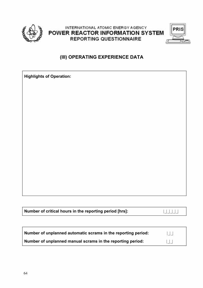
(III) OPERATING EXPERIENCE DATA
Highlights of Operation:
Number of critical hours in the reporting period [hrs]: |_|_|_|_|_|
Number of unplanned automatic scrams in the reporting period: |_|_|
Number of unplanned manual scrams in the reporting period: |_|_|
64

(IV) OUTAGE DATA
Start Date:[yyyymmdd]
Duration:[hours]
Energy Loss (net): [MWe·h]
Type Code: Cause Code:
|_|_|_|_|_|_|_|_| |_|_|_|_| |_|_|_|_|_|_| |_|_|/|_| |_|/|_|_|.|_|_|Description of the outage (cause and mode):
Start Date:[yyyymmdd]
Duration:[hours]
Energy Loss (net): [MWe·h]
Type Code: Cause Code:
|_|_|_|_|_|_|_|_| |_|_|_|_| |_|_|_|_|_|_| |_|_|/|_| |_|/|_|_|.|_|_|Description of the outage (cause and mode):
Start Date:[yyyymmdd]
Duration:[hours]
Energy Loss (net): [MWe·h]
Type Code: Cause Code:
|_|_|_|_|_|_|_|_| |_|_|_|_| |_|_|_|_|_|_| |_|_|/|_| |_|/|_|_|.|_|_|Description of the outage (cause and mode):
65

(V) HEAT PRODUCTION DATA
Section to be added after completion of two related IAEA projects:
A2.06 - Co-generation and heat application
A2.04 - Nuclear desalination
One of possible data elements:
Equivalent non-electrical energy generated (NEG) (net) [MWe·h] |_|_|_|_|_|_|_|
66

OPERATING EXPERIENCE WITH NUCLEAR POWER PLANTS Version 2.1, October 2001
PART 2: REPORTING INSTRUCTIONS
Note: Guidance for these data elements is also provided in the Part 3: "Descriptions of PRIS International Performance Indicators”.
I. Production Data
Year
Enter the year of operation in the form of yyyy.
IAEA plant unit code
Enter the PRIS reactor code.
Station name and unit number
Enter the station name and unit number, which of data is reported.
Reference Unit Power (net) [MWe]
Enter the reference unit power (net), expressed in units of megawatt (electrical). The reference unit power is the maximum (electrical) power that could be maintained continuously throughout a prolonged period of operation under reference ambient conditions. The power value is measured at the unit outlet terminals, i.e. after deducting the power taken by unit auxiliaries and the losses in the transformers that are considered integral parts of the unit.
The reference unit power value should include also the electrical equivalent of the portion of energy delivered in the form of steam/heat that might have been used for non-electrical applications. However, this applies only to the units, where the heat production may reduce the unit electrical power below its maximum value.
If a maximum power capability has been determined by formal test, the reference unit power is determined by correcting test results to reference ambient conditions. If a formal test has not been performed, the reference power should be based on design values, adjusted for reference ambient conditions. The reference unit power is expected to remain constant unless following design changes, or a new permanent authorization, the management decides to amend the original value. (It is recognized that the reference unit power may be based upon an authorized maximum unit thermal power, and in these cases, the "reference unit power (net)" corresponding to the authorized maximum unit thermal power should be used for simplicity in the calculations.)
67

Reference Unit Power Revisions and Dates of Revisions
Enter any changes in the reference unit power (net) that are foreseen to be permanent and which occurred during the year. Note that regulatory limitations for the net reference unit power of a non-permanent nature should not be reported here but as a partial outage due to regulatory limitation.
Does your plant supply heat for non-electrical applications?
Please tick the appropriate box according to the actual conditions at your plant. If the answer is yes, i.e. your plant produces a part of its power in form of heat (supplies steam for non-electrical applications to off-site consumers), please report also the amount of thermal energy using the Heat Production Data Sheet (Section V) of this Questionnaire. However, this applies only to those plants, where the heat production may reduce the unit electrical power below the reference unit power.
Monthly Energy Generation (net) during the year,Energy Generated (net), EG [MWe h]Enter the net electrical energy produced during the reference period as measured at the unit outlet terminals, i.e. after deducting the electrical energy taken by unit auxiliaries and the losses in transformers that are considered integral parts of the unit.
On-line Hours, t [hours]Enter the total clock hours in the month during which the unit operated with at least one main generator connected to the grid.
Reference Period, T [hours] Generally, enter the total number of hours in the calendar month.For units being commissioned during the month, enter the clock hours from the beginning of the month or the first connection to the grid, whichever comes last, to the end of the month.For units being in commercial operation at the beginning of the month, enter the clock hours from the beginning of the month to the end of the month or to the last disconnection from the grid before permanent shutdown, whichever comes first.
Lifetime Cumulative Energy Generation (net) [GWe h]
Enter net energy generated since the first connection to the grid, including the electrical equivalent of thermal energy used for non-electrical applications. For its actual value, add the total EG for the current reporting period to the last reported Lifetime Cumulative Energy Generation value.
68
II. Unavailability Data
For the purpose of the outage coding system, the unit unavailability is defined as a status when the plant is not able to operate at its reference power. This condition, which may be under or beyond plant management control, should only reflect lack of availability of the plant itself, regardless of energy demand, transmission grid condition or political situation in the country. It follows from the definition, that the term "outage" is more general and does not always imply unit unavailability. In other words, some outages may occur, even though the unit is fully available.
In the Unit Unavailability Data form, enter only those energy losses caused by plant unavailability (full or partial) as defined above. If the power plant was operated at reduced power lower than the reference unit power, although it would be able to operate at the reference unit power, the energy loss incurred should not be entered in the Unit Unavailability Data form. Such energy losses that may be due to grid failure, load following operation, government/court decision or stretch-out operation do not constitute other energy loss for the purpose of EAF calculations. For completeness of information of lost energy, however, these energy losses should be reported in the Outage Data form. (See the outage cause codes (J), (K), (M), (R), (S), (T) and (U) in Chapter IV of the Reporting Instructions).
The calculation of energy losses due to reduced unit availability is always related to the reference unit power. If the unit availability is reduced for two or more concurrent reasons (an unplanned equipment failure during planned power reduction for maintenance), the energy loss due to the equipment failure is calculated as if the unit was operated at the reference power at the moment of the failure.
Three types of energy losses caused by unit unavailability are defined in PRIS: planned energy losses, unplanned energy losses due to causes within the control of the plant management and other energy losses due to constraints that cannot be controlled by the plant management.
Planned Energy Losses (net), PEL [MW(e) h]
Enter the energy, expressed in megawatt-hours (electric), that was not delivered during the month because of planned shutdowns or planned load reductions due to causes under the plant management control.
The shutdowns or load reductions are considered planned, if they are scheduled at least four weeks in advance (generally at the time when the annual overhaul, refuelling or maintenance programme is established), and if the beginning of the unavailability period can be largely controlled and deferred by plant management.
Unplanned Energy Losses (net), UEL [MW(e) h]
Enter the energy, expressed in megawatt-hours (electric), that was not delivered during the month because of unplanned shutdowns, unplanned load reductions or outage extensions due to causes under the plant management control.
The shutdowns or load reductions due to causes under plant management control are considered unplanned, if they are not scheduled at least four weeks in advance.
When evaluating UEL, the unit is supposed to be running under reference ambient conditions.
69

Forced energy losses FEL [(MW(e) h)] In this column, enter the energy, expressed in megawatt-hours (electric), that was not delivered during the month because of unplanned shutdowns or unplanned load reductions due to causes under the plant management control.
Extensions of planned energy losses EPL [(MW(e) h)]In this column, enter the energy, expressed in megawatt-hours (electric), that was not delivered during the month due to unplanned extensions of planned load reductions or shutdowns, if causes of these extensions were under the plant management control.
Additional information of planned and unplanned energy losses is provided in the Section 4, “Outage Data (Type code)” and in the Part 3: “Definitions of Performance Indicators”.
Other energy losses (net), XEL [(MW(e) h)]
Enter the energy, expressed in megawatt-hours (electric), that was not delivered during the month due to constraints reducing plant availability and being beyond the plant management control.
Energy losses caused by the following conditions should be reported here,
• Environmental conditions (seasonal variations in cooling water temperature, flood, storm, lightning, lack of cooling water due to drought, tidal valves, high sea or water intake restrictions that could not be prevented by operator action)
• Fuel coastdown (power reduction at the end of fuel cycle resulting in release of a positive reactivity to compensate for high fuel burn up)
• Restrictions on supply and services due to external constraints (lack of funds due to delayed payments from customers, disputes in fuel industries, fuel-rationing, labour strike outside the plant, spare part procurement difficulties etc.)
III. Operating experience data
Highlights of operation
State briefly the general performance and operational mode of the plant over the reporting period e.g.• Operation at full power in base load mode• Load-following for a period• Shut-down for a period• Major achievements leading to increased availability
Describe the significant factors affecting energy generation over the reporting period, e.g.• Limitations introduced by regulatory bodies• Limitations due to fuel management• Shortage of consumables• Personnel factors• Equipment performance• Environmental conditions
70

Number of critical hours in the reporting period:
Enter the number of hours during the reporting period when the reactor was critical.
Number of unplanned automatic scrams in the reporting period:
Enter the number of unplanned automatic scrams that occurred during the reporting period while the reactor was critical.
Number of unplanned manual scrams in the reporting period:
Enter the number of unplanned manual scrams that occurred during the reporting period while the reactor was critical.
IV. Outage data
For the purpose of PRIS coding, the outage is defined as any status of a reactor unit, when its actual output power is lower than the reference unit power for a period of time. By this definition, the outage includes both power reduction and unit shutdown, however it is recognised that in a common understanding it may mean the shutdown only.
Report all significant outages including outage extensions and reactor scrams. The outage is considered significant, if the loss in the energy production corresponds to at least ten hours of continuous operation at the reference unit power or if it has been caused by an unplanned reactor scram (even if the unit had been shut down for less than 10 hours). It is desirable to report also smaller than significant outages. If more outages occurred at a time, they would be considered as separate outages and reported as if the unit was operating at the reference power.
The reactor scram is defined as a reactor shutdown achieved by rapid insertion of negative reactivity into the reactor core, which can be performed either manually or automatically. All unplanned reactor scrams must be reported, even if they occurred after the unit was disconnected some time after the unit was disconnected from grid (when the reactor remained at power, e.g. upon the main output breaker trip). Planned scrams performed as a part of planned tests are not reported.
The outage extension is defined as the unplanned portion of a planned outage, causing prolongation of the planned outage beyond its originally planned completion date. Outage extension must be always reported as unplanned, unless it is announced at least four weeks in advance. The planned outage extensions are considered a part of the planned outages and are not reported separately.
Start date
Enter the first day of the outage in the form of “yyyymmdd”, e.g. 20001228 for December 28, 2000. If no start date can be specified (e.g. for a continuous load following operation), enter the first day of the reporting period. The same applies if an outage extends from the previous reporting period.
Duration [hours]
Enter the total time of the outage measured in full clock hours (rounded) from the beginning of the reporting period or the outage, whichever comes last, to the end of the
71

reporting period or the outage, whichever comes first. The time includes both the power decrease and power rise period.
If a part of the outage extends to the next reporting period, the corresponding outage duration is coded for each reporting period separately. For intermittent outages (e.g. due to load following operation), enter cumulative data for the reporting period. For reactor scrams after disconnection of the unit from the grid, no outage duration is reported (the field is left blank).
Energy Loss (net) [(MW(e) h)]
Enter the total energy expressed in megawatt-hours (electric) that has not been delivered to the grid or other consumers9 due to the outage.
Energy losses are calculated separately for each outage. If several outages are concurrent for a period of time, energy loss for each outage is reported as if the unit was operated at the reference power at the beginning of the outage. For reactor scrams after disconnection of the unit from the grid, no energy loss is reported (the field is left blank).
For intermittent outages (e.g. due to load following operation), enter cumulative data for the reporting period.
Type code
Enter a two- or three-character code for the outage type. The individual outage types will be coded as follows:
TABLE 4-1. FIRST CHARACTER
Code Description P Planned outage due to causes under the plant management controlU Unplanned outage due to causes under the plant management controlX Outage due to causes beyond the plant management control ("external")
An outage is considered planned, if it has been scheduled at least four weeks in advance.An outage is considered unplanned, if it has not been scheduled at least four weeks in advance.The “external” outages may be also considered planned or unplanned. Although this aspect is not explicitly coded, adding the third character (see below) to the "external" outage code will imply the unplanned “external” outage.
In general, any change in the planned outage start date is considered unplanned, unless it is announced at least four weeks in advance. If the start date is anticipated, the outage is considered unplanned until the originally scheduled start date. If the start date is postponed, the outage is still considered planned until the originally scheduled completion date. Any extension of the planned outage beyond the original completion date is considered unplanned, unless it is announced at least four weeks in advance. The unplanned portions of planned outages due to changes in outage start date should be coded as separate outages.
9 For non-electrical applications.
72

Exceptions from this rule are provided in the Part 3, Detailed Descriptions of PRIS Performance Indicators.
TABLE 4-2. SECOND CHARACTER
Code Description F Full outageP Partial outage
An outage is considered full if the actual unit output power has been reduced to zero percent (unit disconnected from all off-site power supply lines). An outage is considered partial if the actual unit output power is lower than its reference value, but is greater than zero percent.
TABLE 4-3. THIRD CHARACTER (FOR UNPLANNED OUTAGES ONLY)
Code Description 1 Controlled shutdown or load reduction that could be deferred but had to be
performed earlier than four weeks after the cause occurred or before the next refuelling outage, whatever comes first
2 Controlled shutdown or load reduction that had to be performed in the next 24 hours after the cause occurred
3 Outage extension 4 Reactor scram, automatic 5 Reactor scram, manual.
The third character should be assigned also to outages due to causes beyond plant management control ("external"), which can be considered unplanned (e.g. the cause codes J, M, N, R, T and U below).
Thus the outage type may have one of the following codes:
PF or PPUF1-5 or UP1-3XF or XP XF1-5 or XP1-3
Cause code
At each outage type, enter one- to five-character code describing the outage cause and the system primarily involved or affected in the outage.
First character represents a direct cause of the outage.
The direct cause is defined as an immediate action or condition that has directly resulted in the outage. For example, if a minor equipment failure, as an oil leak dropping on a hot pipeline or a short-circuit in a non-vital switchgear cabinet, results in an extensive fire that directly causes an outage, the fire is considered the direct cause of the outage.
For a particular outage (full or partial), only one cause may be selected.
If outages occur successively, they must be reported as separate outage due to different causes. For example, if unit power was first reduced due to an equipment failure, but the unit subsequently tripped due to a human error when responding to the failure, these incidents should be reported as two separate outages caused by equipment failure and
73

human factor respectively. Similarly, partial and full outage following immediately one upon the other and having the same direct cause must be reported separately.
In the first character position, enter one letter from the below table of outage direct causes.
TABLE 4-4. DIRECT CAUSES OF OUTAGES
Code10 Description
A Plant equipment failure B Refuelling without a maintenance C Inspection, maintenance or repair combined with refuelling D Inspection, maintenance or repair without refuellingE Testing of plant systems or componentsF Major back-fitting, refurbishment or upgrading activities with refuelling G Major back-fitting, refurbishment or upgrading activities without refuellingH Nuclear regulatory requirements J Grid failure or grid unavailability K Load-following (frequency control, reserve shutdown due to reduced energy
demand) L Human factor related M Governmental requirements or Court decisions N Environmental conditions (flood, storm, lightning, lack of cooling water due to
dry weather, cooling water temperature limits etc.) P Fire R External restrictions on supply and services (lack of funds due to delayed
payments from customers, disputes in fuel industries, fuel-rationing, labour strike outside the plant11, spare part delivery problems etc.)
S Fuel management limitation (including high flux tilt, stretch out or coast-down operation)
T Offsite heat distribution system unavailability U Security and access control Z Others
Planned outages may be due to causes coded B, C, D, E, F, G; unplanned outages may be due to causes coded A, H, L, P; "external" outages may be due to causes coded J, K, M, N, R, T and U. The cause coded S can apply to planned, unplanned and "external" outages.
Causes related to equipment (A), repair (D), testing (E), back-fitting (F, G), nuclear regulatory requirements (H), human actions (L), environmental conditions (N), fire (P), fuel management (S) and other (Z) should, whenever possible, be followed by the numerical code of the plant system affected.
The second to fifth characters represent the plant system primarily involved/affected in the outage.
10 The letters “I”, “O” and “Q” have been deliberately omitted to avoid confusing with digits “0” and “1”. 11 Outages caused by plant personnel strikes should be coded “L”, Human factor related.
74

In the second to fifth- character positions, enter a code of the particular system. Choose a system code from the below table.
For a single outage (full or partial), only one system may be selected. If two or more systems were involved in the outage, select either the system directly causing the outage or the one being most significantly affected.
If no particular system could be specified from the general system group, enter the general system code “xx.00”
In case a particular system was involved in the outage, but no suitable code was found in the list, choose the appropriate general system group and enter the “other” code ”xx.99”.
If no system was involved/affected in the outage, leave blank the second to fifth characters in the outage cause code.
TABLE 4-5. PLANT SYSTEMS POSSIBLY INVOLVED IN THE OUTAGE
Code System Description
Nuclear Systems
11.00 Reactor and Accessories 11.01 Reactor vessel and main shielding (including penetrations and nozzles) 11.02 Reactor core (including fuel assemblies) 11.03 Reactor internals (including steam separators/dryers - BWR, graphite, pressure
tubes)11.04 Auxiliary shielding and heat insulation 11.05 Moderator and auxiliaries (PHWR) 11.06 Annulus gas system (PHWR/RBMK) 11.99 None of the above systems
12.00 Reactor I&C Systems12.01 Control and safety rods (including drives and special power supply) 12.02 Neutron monitoring (in-core and ex-core) 12.03 Reactor instrumentation (except neutron) 12.04 Reactor control system 12.05 Reactor protection system 12.06 Process computer 12.07 Reactor recirculation control (BWR) 12.99 None of the above systems
13.00 Reactor Auxiliary Systems 13.01 Primary coolant treatment and clean-up system 13.02 Chemical and volume control system 13.03 Residual heat removal system (including heat exchangers) 13.04 Component cooling system 13.05 Gaseous, liquid and solid radwaste treatment systems 13.06 Nuclear building ventilation and containment inerting system 13.07 Nuclear equipment venting and drainage system (including room floor
drainage)
75

13.08 Borated or refuelling water storage system 13.09 CO2 injection and storage system (GCR) 13.10 Sodium heating system (FBR) 13.11 Primary pump oil system (including RCP or make-up pump oil) 13.12 D2O leakage collection and dryer system (PHWR) 13.13 Essential auxiliary systems (GCR)
13.99 None of the above systems
14.00 Safety Systems 14.01 Emergency core cooling systems (including accumulators and core spray
system) 14.02 High pressure safety injection and emergency poisoning system 14.03 Auxiliary and emergency feedwater system 14.04 Containment spray system (active) 14.05 Containment pressure suppression system (passive) 14.06 Containment isolation system (isolation valves, doors, locks and penetrations) 14.07 Containment structures 14.08 Fire protection system 14.99 None of the above systems
15.00 Reactor Cooling Systems 15.01 Reactor coolant pumps/blowers and drives 15.02 Reactor coolant piping (including associated valves) 15.03 Reactor coolant safety and relief valves (including relief tank) 15.04 Reactor coolant pressure control system 15.05 Main steam piping and isolation valves (BWR) 15.99 None of the above systems
16.00 Steam generation systems 16.01 Steam generator (PWR), boiler (PHWR, AGR), steam drum vessel (RBMK,
BWR) 16.02 Steam generator blowdown system 16.03 Steam drum level control system (RBMK, BWR) 16.99 None of the above systems
17.00 Safety I&C Systems (excluding reactor I&C) 17.01 Engineered safeguard feature actuation system 17.02 Fire detection system 17.03 Containment isolation function 17.04 Main steam/feedwater isolation function 17.05 Main steam pressure emergency control system (turbine bypass and steam
dump valve control) 17.06 Failed fuel detection system (DN monitoring system for PHWR) 17.07 RCS integrity monitoring system (RBMK)
17.99 None of the above systems
Fuel and Refuelling Systems
21.00 Fuel Handling and Storage Facilities 21.01 On-power refuelling machine 21.02 Fuel transfer system
76

21.03 Storage facilities, including treatment plant and final loading and cask handling facilities
21.99 None of the above systems
Secondary plant systems
31.00 Turbine and auxiliaries 31.01 Turbine 31.02 Moisture separator and reheater 31.03 Turbine control valves and stop valves 31.04 Main condenser (including vacuum system) 31.05 Turbine by-pass valves 31.06 Turbine auxiliaries (lubricating oil, gland steam, steam extraction) 31.07 Turbine control and protection system 31.99 None of the above systems
32.00 Feedwater and Main Steam System 32.01 Main steam piping and valves 32.02 Main steam safety and relief valves 32.03 Feedwater system (including feedwater tank, piping, pumps and heaters) 32.04 Condensate system (including condensate pumps, piping and heaters) 32.05 Condensate treatment system 32.99 None of the above systems
33.00 Circulating Water System 33.01 Circulating water system (pumps and piping/ducts excluding heat sink system) 33.02 Cooling towers / heat sink system 33.03 Emergency ultimate heat sink system 33.99 None of the above systems
34.00 Miscellaneous Systems 34.01 Compressed air (essential and non-essential / high-pressure and low-pressure) 34.02 Gas storage, supply and cleanup systems (nitrogen, hydrogen, carbon dioxide
etc.)34.03 Service water / process water supply system (including water treatment) 34.04 Demineralized water supply system (including water treatment) 34.05 Auxiliary steam supply system (including boilers and pressure control
equipment) 34.06 Non-nuclear area ventilation (including main control room) 34.07 Chilled water supply system 34.08 Chemical additive injection and makeup systems 34.09 Non-nuclear equipment venting and drainage system 34.10 Communication system 34.99 None of the above systems
35.00 All other I&C Systems 35.01 Plant process monitoring systems (excluding process computer) 35.02 Leak monitoring systems 35.03 Alarm annunciation system 35.04 Plant radiation monitoring system 35.05 Plant process control systems
77

35.99 None of the above systems
Electrical Systems
41.00 Main Generator Systems 41.01 Generator and exciter (including generator output breaker) 41.02 Sealing oil system 41.03 Rotor cooling gas system 41.04 Stator cooling water system 41.05 Main generator control and protection system 41.99 None of the above systems
42.00 Electrical Power Supply Systems 42.01 Main transformers 42.02 Unit self-consumption transformers (station, auxiliary, house reserve etc.) 42.03 Vital AC and DC plant power supply systems (medium and low voltage) 42.04 Non-vital AC plant power supply system (medium and low voltage) 42.05 Emergency power generation system (e.g. emergency diesel generator and
auxiliaries)42.06 Power supply system logics (including load shed logic, emergency bus transfer
logic, load sequencer logic, breaker trip logic etc.) 42.07 Plant switchyard equipment 42.99 None of the above systems
Description of the outage
Describe briefly the direct cause of the outage, the operational mode of the plant at the time of the outage occurrence and specify the systems involved including their components. This field should provide at least a name describing nature of the outage.
In the cause description, specify in more details the general causes: the type of human factor (operator mistake, omission, failure to monitor plant processes), the type of equipment failure (spurious actuation of a system, component trip, damage or malfunction), the type of adverse environmental condition (frost, lightning, high sea), the type of load following operation (frequency control, reserve shutdown), the cause of fire etc. If applicable, specify also the cause coded Z – Others, the system involved coded “xx.99” or other major systems involved, if not coded.
For the operational mode description, choose one of the following operational modes describing the status of the unit immediately before the outage.
• Power operation • Start up/shutdown operation • Hot standby (reactor subcritical)• Hot shutdown (reactor subcritical)• Cold shutdown (reactor subcritical)• Reactor pressure vessel open
If applicable, please provide in more details the actual type of operation/activity in the particular mode (e.g. power ascension after an outage; steady power operation at rated or reduced power upon the grid dispatcher’s request etc.).
78

V. Heat Production Data
Some power plant units produce a portion of their output energy in the form of heat/steam for non-electrical applications (desalination, district heating and industrial heat). This energy should be also reported, provided the production of heat/steam reduces the actual output electrical power below the reference unit power as defined in Section 1.
Instruction for reporting the heat production data will result from two related IAEA projects:A2.06 - Co-generation and heat application A2.04 - Nuclear desalination.
Following completion of these projects, the reported instructions will be included in this section. One of the reported data elements may be (see the Questionnaire Form:
Equivalent non-electrical energy generated (net), NEG [MW(e) h]
Enter the sum of monthly electrical equivalent of energy supplied in the form of steam expressed in megawatts-hours (electric). It should be equal to the difference between the possible annual total energy production (combined electrical and thermal) based on the reference unit power, and the sum of monthly energy generation, as reported in Section I under the "TOTAL" of the EG column.
To convert the thermal energy into electrical energy, the formulas provided by the IAEA may be applied.
79

Annex 5
DETAILED DESCRIPTIONS OF PRIS PERFORMANCE INDICATORS
Introduction
This document provides descriptions of international performance indicators reported in the IAEA Power Reactor Information System (PRIS).
The indicators load factor, operation factor and energy availability factor have been used in PRIS since the beginning of the databank operation. In 1990 two UNIPEDE / WANO performance indicators, i.e. unit capability factor and unplanned capability loss factor, were included in PRIS.
The other three indicators presented, i.e. planned capability loss factor, external capability loss factor and energy unavailability factor can be easily calculated from those given above. The Advisory Group Meeting on Performance Analysis of Nuclear Power Plants recommended to harmonize definitions of PRIS and UNIPEDE / WANO. An effort has been made to use, where adequate, the definitions and descriptions of performance indicators as used by these organisations.
Accordingly, the definitions for three additional indicators: operating period forced loss rate (new proposed WANO indicator), unplanned automatic and unplanned manual scrams (WANO indicator: unplanned automatic scrams only) have been included here. In preparing the document the following information sources were consulted:
- PRIS annual questionnaire - (Revision September 1990)
- Conclusions and recommendations of the Advisory Group Meetings on Performance Analysis of Nuclear Power Plants,
- Descriptions of PRIS performance indicators, November 1990,
- International nuclear power plant performance indicator definitions (WANO set - 2000)
- UNIPEDE terminology, (June 1991).
Load factor (LF)
PurposeThe purpose of this indicator is to provide the ratio of the actual unit energy production compared to the reference energy generation, over a certain period of time. This indicator reflects the actual energy utilization of the unit for electricity and heat production.
Definition
Load factor, for a given period, is the ratio of the energy which the power unit has produced over that period divided by the energy it would have produced at its reference power capacity over that period.
Energy generation (net) is the electrical and non-electrical energy produced during a given time period as measured at the unit outlet terminals, i.e. after deducting the energy taken by
80

unit auxiliaries and the losses in transformers and heat exchangers that are considered integral parts of the unit.
Reference energy generation (net) is the energy that could be produced during a given time period if the unit were operated continuously at reference unit power (net).
Data elements
Following data are required to calculate this indicator for each unit
- energy generation (net) expressed in units of megawatt-hours (electrical)
- reference energy generation (net) expressed in units of megawatt-hours (electrical).
Calculations
The unit load factor is calculated for each period as shown below:
Value for a unit: LF (%) = EG x 100 REG
Where:
- EG = net energy generation (MW.h) for the period
- REG = reference energy generation (net) (MW.h) for the period.
Clarifying notes
• The reference energy generation (net) is the product of reference unit power (net) and the reference period in hours.
• The reference unit power is the maximum (electrical) power that could be maintained continuously throughout a prolonged period of operation under reference ambient conditions. The power value is measured at the unit outlet terminals, i.e. after deducting the power taken by unit auxiliaries and the losses in the transformers that are considered integral parts of the unit.
The reference unit power value should include also the electrical equivalent of the portion of energy delivered in the form of steam/heat that might have been used for non-electrical applications. However, this applies only to the units, where the heat production may reduce the unit electrical power below its maximum value.
If a maximum power capability has been determined by formal test, the reference unit power is determined by correcting test results to reference ambient conditions. If a formal test has not been performed, the reference power should be based on design values, adjusted for reference ambient conditions. The reference unit power is expected to remain constant unless following design changes, or a new permanent authorization, the management decides to amend the original value. (It is recognized that the reference unit power may be based upon an authorized maximum unit thermal power, and in these cases, the "reference unit power (net)" corresponding to the authorized maximum unit thermal power should be used for simplicity in the calculations.)
• Although the load factor indicator refers to the energy production provided to the grid, implying the use of net values, it is possible to calculate this indicator using gross values.
81

In that case, the two energy figures (production, and reference energy generation) must be of the same kind.
• Nuclear thermal power is the nuclear thermal power output of the unit as derived from the most accurate heat balance measurement.
• The reference ambient conditions are environmental conditions representative of the annual mean (or typical) conditions for a unit. It is expected that historical heat sink temperatures will be used to determine the reference ambient conditions. The same reference ambient conditions will generally apply for the life of the unit. Periodic review of these reference conditions is not required.
• The reference period hours are the total number of hours in the pre-defined calendar time.
For units in power ascension at the end of the period, the clock hours from the beginning of the period or the first energy production, whichever comes last, to the end of the period.
For units in commercial operation at the end of the period, the clock hours from the beginning of the period or of commercial operation, whichever comes last, to the end of the period or permanent shutdown, whichever comes first.
Example indicator calculation
• Reference unit power : 985 MW(e).
• Actual energy production (EG) during the year (8760 hours) : 5 950 000 MW(e).h.
• Reference energy generation (1 year) = (REG)
REG = (985 MW(e)) x (8760 h) = 8 628 600 MW(e).h
Load factor = 5 950 000 x 100 = 69% 8 628 600
82
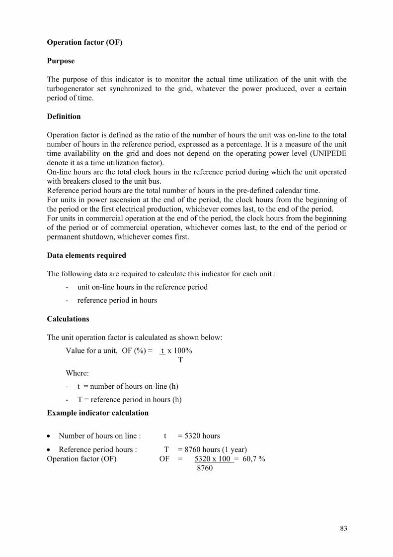
Operation factor (OF)
Purpose
The purpose of this indicator is to monitor the actual time utilization of the unit with the turbogenerator set synchronized to the grid, whatever the power produced, over a certain period of time.
Definition
Operation factor is defined as the ratio of the number of hours the unit was on-line to the total number of hours in the reference period, expressed as a percentage. It is a measure of the unit time availability on the grid and does not depend on the operating power level (UNIPEDE denote it as a time utilization factor). On-line hours are the total clock hours in the reference period during which the unit operated with breakers closed to the unit bus. Reference period hours are the total number of hours in the pre-defined calendar time. For units in power ascension at the end of the period, the clock hours from the beginning of the period or the first electrical production, whichever comes last, to the end of the period. For units in commercial operation at the end of the period, the clock hours from the beginning of the period or of commercial operation, whichever comes last, to the end of the period or permanent shutdown, whichever comes first.
Data elements required
The following data are required to calculate this indicator for each unit :
- unit on-line hours in the reference period
- reference period in hours
Calculations
The unit operation factor is calculated as shown below:
Value for a unit, OF (%) = t x 100% T
Where:
- t = number of hours on-line (h)
- T = reference period in hours (h)
Example indicator calculation
• Number of hours on line : t = 5320 hours
• Reference period hours : T = 8760 hours (1 year) Operation factor (OF) OF = 5320 x 100 = 60,7 % 8760
83

Unit capability factor (UCF)
Purpose
The purpose of this indicator is to monitor progress in attaining high unit and industry energy production reliability. This indicator reflects effectiveness of plant programs and practices in maximizing available electrical generation, and provides an overall indication of how well plants are operated and maintained.
Definition
Unit capability factor is defined as the ratio of the available energy generation over a given time period to the reference energy generation over the same time period, expressed as a percentage. Both of these energy generation terms are determined relative to reference ambient conditions.
Available energy generation is the energy that could have been produced under reference ambient conditions considering only limitations within control of plant management, i.e. plant equipment and personnel performance, and work control.
Reference energy generation is the energy that could be produced if the unit were operated continuously at full power under reference ambient conditions. Reference ambient conditions are environmental conditions representative of the annual mean (or typical) ambient conditions for the unit.
Data elements
The following data are required to determine each unit's value for this indicator:
- Reference energy generation, expressed in units of megawatt-hours (electric).
- Planned energy loss: the energy that was not produced during the period because of planned shutdowns or load reductions due to causes under plant management control. Energy losses are considered planned if they are scheduled at least four weeks in advance. Energy losses considered to be under plant management control are further defined in the clarifying notes. Planned energy loss is expressed in units of megawatt-hours.
- Unplanned energy loss: the energy that was not produced during the period because of unplanned shutdowns, outage extensions, or load reductions due to causes under plant management control. Energy losses are considered to be unplanned if they are not scheduled at least four weeks in advance. Energy losses considered to be under plant management control are further defined in the clarifying notes. Unplanned energy loss is expressed in units of megawatt-hours.
Calculations
The unit capability factor is determined for each period as shown below: • value for a unit, UCF (%) = (REG - PEL - UEL) x 100 % REG
84

Where:
- REG = reference energy generation for the period
- PEL = total planned energy losses for the period
- UEL = total unplanned energy losses for the period
• planned energy loss: PEL = (PPL x HRP)
Where:
- PPL = planned power loss: the power decrease in megawatts due to a planned event
- HRP = hours operated at reduced power (or shutdown) due to the planned event
Note: The total planned energy loss for the period is the sum of the losses from all planned events.
• unplanned energy loss: UEL = (UPL x HRU)
Where:
- UPL = unplanned power loss: the power decrease in megawatts due to an unplanned event
- HRU = hours operated at reduced power (or shutdown) due to the unplanned event
Note: The total unplanned energy loss for the period is the sum of the losses from all unplanned events.
• value for the industry = median of the unit values
Data qualification requirements
Data for new units is included in the calculation of industry values beginning January 1 of the first calendar year following commercial operation.
Clarifying notes
• The reference energy generation is determined by multiplying the reference unit power by the period hours.
• The reference unit power is the maximum power capability of the unit under reference ambient conditions. If a maximum power capability has been determined by formal test, the reference unit power is determined by correcting test results to reference ambient conditions. If a formal test has not been performed, the reference power should be based on design values, adjusted for reference ambient conditions. The reference unit power is expected to remain constant unless design changes that affect the capacity are made to the unit.
• The reference ambient conditions are environmental conditions representative of the annual mean (or typical) conditions for a unit. It is expected that historical heat sink temperatures will be used to determine the reference ambient conditions. The same
85

reference ambient conditions will generally apply for the life of the unit. Periodic review of these reference conditions is not required.
• Planned energy losses (those scheduled at least four weeks in advance) caused by the following conditions should be included when computing the unit capability factor because they are considered to be under the control of plant management:
- refueling or planned maintenance outages
- planned outages or load reductions for testing, repair, or other plant equipment or personnel-related causes
• Energy losses due to tests may be considered as planned if they are identified at least four weeks in advance and are part of a regular program, even if the precise time of the test is not decided four weeks in advance.
• Unplanned energy losses caused by the following conditions should be included when computing the unit capability factor because they are considered to be under the control of plant management:
- unplanned maintenance outages
- unplanned outages or load reductions for testing, repair, or other plant equipment or personnel-related causes
- unplanned outage extensions
- unplanned outages or load reductions that are caused by, or prolonged by, regulatory actions taken as a result of plant equipment or personnel performance, or regulatory actions applied on a generic basis to all like plants
• Energy losses due to the following causes should not be considered when computing the unit capability factor because these losses are not considered to be under the control of plant management:
- grid instability or failure
- lack of demand (reserve shutdown, economic shutdown, or load-following)
- environmental limitations (such as low cooling pond level, water intake restrictions, earthquake or deluges that could not be prevented by operator action)
- labor strikes (see clarifying note below)
- fuel coast downs
- seasonal variations in gross dependable capacity due to cooling water temperature variations
• The values of planned or unplanned power losses to be used in computing energy losses due to a particular event are the losses that would have occurred if the unit were operating at the reference power level at the time of the event. The power losses relative to the reference power may be determined by one of the following techniques:
(1) subtracting the actual power level during the event from the power level immediately prior to the event when the power was at or near the reference power level,
(2) computing the power level reduction that would have occurred with the unit at the reference power level, or
(3) using historical data from similar events occurring at the reference power level.
86

For example, if a unit experiences a 10 MW power loss due to an equipment problem while operating at 75 % of the reference power, and it is determined from calculations or from similar events that have occurred at the reference power that the same equipment problem would have resulted in a 20 MW power loss at the reference power level, then 20 MW should be used when computing the energy loss.
• For events involving planned or unplanned outages and start-up following these outages, the reference unit power should be used as the basis for computing power losses.
• If energy losses during an event occur due to a combination of causes under management control and causes outside of management control, the portion of the total losses caused by factors under management control should be identified and included when computing the unit capability factor.
• Outages or load reductions caused by labor strikes that occur while the unit is operating are normally not included as planned or unplanned energy losses because these energy losses are not under the direct control of plant management. However, if during the strike the unit becomes incapable of starting or operating because of equipment failures, maintenance, overhauls, or other activities such as refueling, then the energy losses during the time the unit is inoperable are included. If a labor strike occurs during an outage, any outage extensions are included as energy losses as long as the unit is incapable of being restarted because of equipment failures, maintenance, overhauls, or other activities such as refueling.
• In general, changes in an outage or load reduction start date must be announced at least four weeks in advance to be considered as "planned." However, if the grid dispatcher requests a change in the start date less than four weeks in advance, the outage or load reduction is considered to be planned.
The same rule may be used if the change in the start date is decided by plant management, assuming this decision is due to all of the following reasons or circumstances:
The unit is operating in a deregulated environment, and the management decision to modify the planned outage start date is solely to take advantage of economic situations to maximize, on a short term basis, the economic benefit coming from selling the plant electricity output. This economic benefit can be applied to the entire production system of the Utility, not only to the specific unit under consideration.
- The unit is considered as able to run at maximum power during the four-week period prior to the initial planned outage start date.
- Any forced or unplanned outage occurring during this four-week period (or before the new start date) shall not become the reason for putting forward the planned outage.
• If a unit begins an outage or load reduction before the scheduled start date, the energy loss from the beginning of the outage or load reduction to the scheduled start date is an unplanned energy loss.
• If an outage extends beyond the scheduled start-up date, either to complete originally scheduled work or to complete corrective maintenance work on equipment required for start up, all energy losses associated with the outage extension should be considered as unplanned. However, outage extensions to complete discretionary work (i.e. preventive maintenance or modifications) not originally scheduled for completion during the outage should be considered as planned if the work is scheduled at least four weeks in advance. Extended outages can be reclassified from unplanned to planned once corrective maintenance activities required for start-up are completed if any remaining planned
87

activities were scheduled at least four weeks in advance. This clarification also applies to load reductions.
• The scheduled start and end dates of planned outages and load reductions are those dates negotiated with and agreed to by the network and/or grid dispatcher. These dates may differ from dates shown on the detailed schedule of activities used at the unit for directing the outage.
• Energy losses related to load reduction preceding a shutdown and load increases following the shutdown should be categorized as planned or unplanned depending on whether the shutdown is planned or unplanned. For example, energy losses while entering and recovering from a planned outage will be considered as planned losses. If an outage extension (unplanned outage) occurs at the end of a planned outage, the energy loss during recovery from the outage will still be considered as a planned loss because the shutdown was originally caused by a planned outage (see Attachment A, time period 5–6 for an example of this situation.) Energy losses due to required tests following refueling are considered planned losses.
• A unit that is in reserve shutdown will be considered as available if it can be restarted within the normal time required for unit start up. If work on plant equipment is undertaken that would prevent a restart, the energy that potentially could have been produced while the plant was unavailable should be computed and used when determining the unit capability factor, even if the plant was not actually required to start up during the period.
• Either net or gross energy may be used; however, consistency must be maintained for all energy terms. The use of gross energy is more meaningful in certain situations. For example, it is less confusing for multi-unit stations that may power the station electrical loads from one unit.
• As a point of interest, the sum of unit capability factor, unplanned capability loss factor, and planned capability loss factor equals 100 percent over a specific time period. Planned capability loss factor can be calculated from this relationship.
Example of unit capability factor calculation
The following examples and the accompanying power history plot are provided to illustrate methods used in calculating the unit capability factor and the unplanned capability loss factor for a plant under a variety of common situations. The time periods referenced in the example refer to points labeled on the power history plot. Initial Conditions:Reference unit power: 985 MW(e).
It is assumed that this unit has a maximum power output of 1 000 MW(e) under optimum ambient conditions (determined by a formal test). Correction of test results to reference ambient conditions resulted in the reference capacity value of 985 MW(e).
Time period being considered: one year (8 760 hours) Reference energy generation for the period (REG):
(985 MW(e)) x (8 760 hours) = 8 628 600 MW(e).h
Energy Loss Examples:
88

Time
Period Description1 - 2 Power reduction of 100 MW(e) for 12 hours due to circulating water pump failure. The unit was
operating at reduced power due to a load following at the time of the pump failure. The power reduction caused by this failure would have been 201 MW(e) if the failure had occurred at the reference power level.
UEL = 201 x 12 = 2 412 MW(e).h Unplanned
2 - 3 Reduced power operation due to ambient conditions and fuel coast down. The lost energy generation is not used in calculations.
3 - 4 Planned refueling outage. Scheduled length was 45 days (1 080 hours). The outage begins on the scheduled date.
PEL = 985 x 1 080 = 1 063 800 MW(e).h Planned
4 - 5 Outage extension of 10 days (240 hours) beyond scheduled length to complete all work scheduled for the outage.
UEL = 985 x 240 = 236 400 MW(e).h Unplanned
5 - 6 Power ramp-up following outage. Average power level of 495 MW(e) for three days (72 hours).
PEL = (985 - 495) x 72 = 35 280 MW(e).h Planned
6 - 7 Operation above reference unit capacity due to very cold cooling water. The additional energy generation is not used in calculations.
7 - 8 Shutdown for 32 hours due to reactor scram caused by personnel error.
UEL = 985 x 32 = 31 520 MW(e).h Unplanned
8 - 9 Power ramp-up following the scram. Average power level of 490 MW(e) for 8 hours.
9 - 10 Operation below reference unit capacity due to environmental limitations only. The lost energy generation is not used in calculations.
Calculations for Unit Capability Factor Time
Period Energy Loss
Total planned energy loss (PEL) 3 - 4 1 063 800
5 - 6 35 280 1 099 080 MW(e).h
Total unplanned energy loss (UEL) 1 - 2 2 412
4 - 5 236 400
7 - 8 31 520
8 - 9 3 960 274 292 MW(e).h
Unit Capability Factor (UCF) = (REG - PEL - UEL) x 100% REG
= (8 628 600 - 1 099 080 - 274 292) x 100% 8 628 600
= 84.1% Calculations for Unplanned Capability Loss Factor*
89

Unplanned Capability Loss Factor (UCL) = UEL x 100% REG
= 274 292 x 100% 8 628 600
= 3.2% * This calculation is provided for use with the unplanned capability loss factor detailed description.
1 2 3 4 5 6 7
8 9 10
EQUIPMENT FAILURE
FUEL COASTDOWN
OUTAGE
TIME
OUTAGE EXTENSION
RAMP-UP OPERATOR ERROR
POWER
REFERENCE UNIT
POWERLEVEL
PLANNED LOSSES
UNPLANNED LOSSES
"EXTERNAL" EFFECTS
SCHEDULED
FIG. 5.1. Power Example History.
Point-to-point power level explanations: 0 - 1 reduced power due to load following
1 - 2 reduced power due to equipment failure
2 - 3 reduced power due to ambient conditions and fuel coast-down
3 - 6 unit shutdown (outage) and subsequent ramp-up
6 - 7 increased power due to very cold water
7 - 9 unit shutdown (operator error) and subsequent ramp-up
9 - 10 reduced power due to environmental limitations not under management control
90

Unplanned capability loss factor (UCL)
Purpose
The purpose of this indicator is to monitor industry progress in minimizing outage time and power reductions that result from unplanned equipment failures or other conditions. This indicator reflects the effectiveness of plant programs and practices in maintaining systems available for safe electrical generation.
Definition
Unplanned capability loss factor is defined as the ratio of the unplanned energy losses during a given period of time, to the reference energy generation, expressed as a percentage.
Unplanned energy loss is energy that was not produced during the period because of unplanned shutdowns, outage extensions, or unplanned load reductions due to causes under plant management control. Causes of energy losses are considered to be unplanned if they are not scheduled at least four weeks in advance. Causes considered to be under plant management control are further defined in the clarifying notes.
Reference energy generation is the energy that could be produced if the unit were operated continuously at full power under reference ambient conditions throughout the period. Reference ambient conditions are environmental conditions representative of the annual mean (or typical) ambient conditions for the unit.
Data elements
The following data is required to determine each unit's value for this indicator:
- Unplanned energy losses expressed in units of megawatt-hours (electric). The definition of unplanned energy losses is included as part of the Unit Capability Factor indicator description.
- Reference energy generation, expressed in units of megawatt-hours (electric).
Calculations
The unplanned capability loss factor is determined for each period as shown below:
• value for a unit, UCL(%) = UEL x 100% REG
Where:
- UEL = total unplanned energy losses for the period
- REG = reference energy generation for the period
Note: The total unplanned energy loss for the period is the sum of the losses from all unplanned events. • unplanned energy loss: UEL = (UPL x HRU)
Where:
- UPL = unplanned power loss: the power decrease in megawatts due to an unplanned event
91

- HRU = hours operated at reduced power (or shutdown) due to the unplanned event
• value for the industry = median of the unit values
• unplanned capability loss factors for individual units will be presented for a three-year period to maintain consistency with the three year Unit Capability Factor.
Data qualification requirements
Data for new units is included in the calculation of industry values beginning January 1 of the first calendar year following commercial operation.
Clarifying notes
• The reference energy generation is determined by multiplying the reference unit power by the period hours.
• The reference unit power is the maximum power capability of the unit under reference ambient conditions. If a maximum power capability has been determined by formal test, the reference unit power is determined by correcting test results to reference ambient conditions. If a formal test has not been performed, the reference power should be based on design values, adjusted for reference ambient conditions. The reference unit power is expected to remain constant unless design changes that affect the capacity are made to the unit.
• The reference ambient conditions are environmental conditions representative of the annual mean (or typical) ambient conditions for a unit. It is expected that historical heat sink temperatures will be used to determine the reference ambient conditions. The same reference ambient conditions will generally apply for the life of the unit. Periodic review of these reference conditions is not required.
• Unplanned energy losses caused by the following conditions should be included when computing the unplanned capability loss factor because they are considered to be under the control of plant management:
- unplanned maintenance outages
- unplanned outages or load reductions for testing, repair, or other plant equipment or personnel-related causes
- unplanned outage extensions
- unplanned outages or load reductions that are caused by or prolonged by regulatory actions taken as a result of plant equipment or personnel performance, or regulatory actions applied on a generic basis to all like plants
• Unplanned energy losses due to the following causes should not be included when computing the unplanned capability loss factor because these losses are not considered to be under the control of plant management:
- grid instability or failure
- lack of demand (reserve shutdown, economic shutdown, or load following)
- environmental limitations (such as low cooling pond level, water intake restrictions , earthquake or deluges that could not be prevented by operator action)
92

- labor strikes (see clarifying note below)
- fuel coast downs
- seasonal variations in gross dependable capacity due to cooling water temperature variations
• The values of planned or unplanned power losses to be used in computing energy losses due to a particular event are the losses that would have occurred if the unit were operating at the reference power level at the time of the event. The power losses relative to the reference power may be determined by one of the following techniques:
(1) subtracting the actual power level during the event from the power level immediately prior to the event when the power was at or near the reference power level,
(2) computing the power level reduction that would have occurred with the unit at the reference power level, or
(3) using historical data from similar events occurring at the reference power level.
For example, if a unit experiences a 10 MW power loss due to an equipment problem while operating at 75 % of the reference power, and it is determined from calculations or from similar events that have occurred at the reference power that the same equipment problem would have resulted in a 20 MW power loss at the reference power level, then 20 MW should be used when computing the energy loss.
• For events involving unplanned outages and start up following these outages, the reference unit power should be used as the basis for computing power losses.
• If energy losses during an event occur due to a combination of causes under management control and causes outside of management control, the portion of the total losses that are unplanned and are under management control should be identified and used when computing the unplanned capability loss factor.
• Outages or load reductions caused by labor strikes that occur while the unit is operating are normally not included as unplanned energy losses because these energy losses are not under the direct control of plant management. However, if during the strike the unit becomes incapable of starting or operating because of equipment failures, maintenance, overhauls, or other activities such as refueling, then the energy losses during the time the unit is inoperable are included. If a labor strike occurs during an outage, any outage extensions are included as energy losses as long as the unit is incapable of being restarted because of equipment failures, maintenance, overhauls, or other activities such as refueling.
• In general, changes in an outage or load reduction start date must be announced at least four weeks in advance to be considered as "planned." However, if the grid dispatcher requests a change in the start date less than four weeks in advance, the outage or load reduction is considered to be planned.
The same rule may be used if the change in the start date is decided by plant management, assuming this decision is due to all of the following reasons or circumstances:
The unit is operating in a deregulated environment, and the management decision to modify the planned outage start date is solely to take advantage of economic situations to maximize, on a short term basis, the economic benefit coming from selling the plant electricity output. This economic benefit can be applied to the entire production system of the Utility, not only to the specific unit under consideration.
93

- The unit is considered as able to run at maximum power during the four-week period prior to the initial planned outage start date.
- Any forced or unplanned outage occurring during this four-week period (or before the new start date) shall not become the reason for putting forward the planned outage.
• If a unit begins an outage or load reduction before the scheduled start date, the energy loss from the beginning of the outage or load reduction to the scheduled start date is an unplanned energy loss.
• If an outage extends beyond the scheduled start-up date, either to complete originally scheduled work or to complete corrective maintenance work on equipment required for start-up, all energy losses associated with the outage extension should be considered as unplanned. However, outage extensions to complete discretionary work (i.e., preventive maintenance and modifications) not originally scheduled for completion during the outage should be considered as planned if the work is scheduled at least four weeks in advance. Extended outages can be reclassified from unplanned to planned once corrective maintenance activities required for start-up are completed if any remaining planned activities were scheduled at least four weeks in advance. This clarification also applies to load reductions.
• The scheduled start and end dates of planned outages and load reductions are those dates negotiated with and agreed to by the network and/or grid dispatcher. These dates may differ from dates shown on the detailed schedule of activities used at the unit for directing the outage.
• Energy losses that occur while entering and recovering from an unplanned outage will be considered as unplanned losses. If an outage extension (unplanned outage) occurs at the end of a planned outage, the energy loss during recovery from the outage will still be considered as a planned loss because the shutdown was originally caused by a planned outage. Energy losses due to required tests following refueling are considered planned losses.
• Either net or gross energy may be used; however, consistency must be maintained for all energy terms. The use of gross energy is more meaningful in certain situations. For example, it is less confusing for multi-unit stations that may power the station electrical loads from one unit.
Planned capability loss factor (PCL): The planned capability loss factor can be calculated from the relationship:
UCF + UCL + PCL = 100% over a specific time period
Where:
- UCF = unit capability factor (%)
- UCL = unplanned capability loss factor (%)
Note: PCL replaces the formerly used planned energy unavailability factor (PUF)
94

Operating period forced loss rate (FLR)
Purpose
The purpose of this indicator is to monitor industry progress in minimizing outage time and power reductions that result from unplanned equipment failures, human factor or other conditions during the operating period (excluding planned outages and their possible unplanned extensions). This indicator reflects the effectiveness of plant programs and practices in maintaining systems available for safe electrical generation when the plant is expected to be at the grid dispatcher disposal.
Definition
Operating period forced loss rate is defined as the ratio of the unplanned energy losses during a given period of time, considering only the operating period, to the reference energy generation minus energy losses corresponding to planned outages and their possible unplanned extensions, during the same period, expressed as a percentage.
Unplanned forced energy loss during the operating period is energy that was not produced during that period because of unplanned shutdowns, or unplanned load reductions due to causes under plant management control. Causes of energy losses are considered to be unplanned if they are not scheduled at least four weeks in advance. Causes considered to be under plant management control are further defined in the clarifying notes.
Reference energy generation is the energy that could be produced if the unit were operated continuously at full power under reference ambient conditions throughout the whole period. Reference ambient conditions are environmental conditions representative of the annual mean (or typical) ambient conditions for the unit. Energy losses corresponding to planned outages and their possible unplanned extensions are energy losses that are not produced due to these specific reasons.
Data Elements
The following data is required to determine each unit’s value for this indicator:
- Reference energy generation, expressed in units of megawatt-hours (electric) (REG).
- Planned energy losses, expressed in units of megawatt-hours (electric) (PEL).
- Unplanned energy losses (UEL) – (see definition of the UCF and the UCL) - contains two terms - operating period unplanned forced energy losses (FEL) and unplanned extension of a planned outage energy losses (EPL): UEL=FEL+EPL. (see Note)
- Unplanned forced energy losses (FEL) are those occurring during the operating period, when the unit is considered to be at the disposal of the grid dispatcher. (see Note)
- unplanned extension of a planned outage energy losses (EPL), expressed in units of megawatt-hours (electric) (EPL)
Note: Only two items of UEL, FEL, and EPL are required to be reported.
95

Calculations
The operating period forced loss rate (FLR) is determined for each period as shown below:
• value for a unit, FLR (%) = FEL x 100 % REG - (PEL+EPL)
Where:
- FEL = operating period unplanned forced energy losses for one year
- REG = reference energy generation for one year
- PEL = planned energy losses for one year
- EPL = unplanned extensions of planned outages energy losses for one year
Note: The total operating period unplanned forced energy losses for one year is the sum of the losses from all unplanned forced events: FEL = (FPL x HRU)
Where:
- FPL = operating cycle unplanned forced power loss: the power decreases in megawatts due to an unplanned event during the operating period (excluding possible extensions of planned outages).
- HRU = hours operated at reduced power (or shutdown) due to the unplanned forced event.
• Value for the industry = median of the unit values.
Data qualification requirements
Data for new units is included in the calculation of industry values beginning January 1 of the first calendar year following commercial operation.
Clarifying notes
• The reference energy generation is determined by multiplying the reference unit power by the period hours.
• The reference unit power is the maximum power capability of the unit under reference ambient conditions. If a maximum power capability has been determined by a formal test, the reference unit power is determined by correcting test results to reference ambient conditions. If a formal test has not been performed, the reference power should be based on design values, adjusted for reference ambient conditions. The reference unit power is expected to remain constant unless design changes that affect capacity are made to the unit.
• The reference ambient conditions are environmental conditions representative of the annual mean (or typical) ambient conditions for a unit. It is expected that historical heat sink temperatures will be used to determine the reference ambient conditions. The same reference ambient conditions will generally apply for the unit. Periodic review of these reference conditions is not required.
96

• Unplanned forced energy losses caused by the following conditions should be included when computing the unplanned forced capability loss rate because they are considered to be under the control of plant management:
- Unplanned maintenance outages, excluding extensions of planned outages;
- Unplanned outages or load reductions for unplanned testing, repair, or other plant equipment or personnel-related causes;
- Unplanned outages or load reductions that are caused or prolonged by regulatory actions taken as a result of plant equipment or personnel performance, or regulatory actions applied on a generic basis to all like plants, excluding those associated with extensions of planned outages.
• Unplanned energy losses due to the following causes should not be included when computing the unplanned forced capability loss rate because these losses are not considered to be under the control of the plant management:
- grid instability or failure;
- lack of demand (reserve shutdown, economic shutdown, or load following);
- environmental limitations (for example low cooling pond level, water intake restrictions, earthquakes or deluges that could not be prevented by operator action);
- industrial action (labor strikes) - see clarifying note below;
- fuel coast downs;
- seasonal variations in gross dependable capacity due to cooling water temperature variations.
• The values of planned or unplanned power losses to be used in computing energy losses due to a particular event are the losses that would have occurred if the unit were operating at the reference power level at the time of the event. The power losses relative to the reference power can be determined by one of the following techniques:
(1) subtracting the actual power level during the event from the power level immediately prior to the event when the power was at or near the reference power level;
(2) computing the power level reduction that would have occurred with the unit at the reference power level; or
(3) using historical data from similar events occurring at the reference power level. For example, if a unit experiences a 10 MW power loss due to an equipment problem while operating at 75 % of the reference power, and it is determined from calculations or from similar events that have occurred at the reference power that the same equipment problem would have resulted in a 20 MW power loss at the reference power level, then 20 MW should be used when computing the energy loss.
• For events involving unplanned outages and start up following these outages, the reference unit power should be used as the basis for computing power losses.
• If energy losses during an event occur due to a combination of causes under management control and causes outside of management control, the portion of the total losses that are unplanned and are under management control should be identified and used when computing the unplanned capability loss rate.
• Outages or load reductions caused by labor strikes that occur while the unit is operating are normally not included as unplanned energy losses because these energy losses are not
97

under the direct control of plant management. However, if during the strike the unit becomes incapable of starting or operating because of equipment failures, maintenance, or other unplanned activities, then the energy losses during the time the unit is inoperable are included.
• In general, changes in an outage or load reduction start date must be announced at least four weeks in advance to be considered as "planned." However, if the grid dispatcher requests a change in the start date less than four weeks in advance, the outage or load reduction is considered to be planned.
The same rule may be used if the change in the start date is decided by plant management, assuming this decision is due to all of the following reasons or circumstances:
The unit is operating in a deregulated environment, and the management decision to modify the planned outage start date is solely to take advantage of economic situations to maximize, on a short term basis, the economic benefit coming from selling the plant electricity output. This economic benefit can be applied to the entire production system of the Utility, not only to the specific unit under consideration.
- The unit is considered as able to run at maximum power during the four-week period prior to the initial planned outage start date.
- Any forced or unplanned outage occurring during this four-week period (or before the new start date) shall not become the reason for putting forward the planned outage.
• If a unit begins an outage or load reduction before the scheduled start date, the energy loss from the beginning of the outage or load reduction to the scheduled start date is an unplanned energy loss.
• If an outage extends beyond the scheduled start up date, either to complete originally scheduled work or to complete corrective maintenance work on equipment required for start up, all energy losses associated with the outage extension should be considered as unplanned, but not «forced.»
• The scheduled start and end dates of planned outages and load reductions are those dates negotiated with and agreed to by the network and/or grid dispatcher. These dates may differ from dates shown on the detailed schedule or activities used at the unit for directing the outage.
• Energy losses that occur while entering and recovering from an unplanned outage will be considered as unplanned losses. If an outage extension (unplanned outage) occurs at the end of a planned outage, the energy loss during recovery from the outage will still be considered as a planned loss because the shutdown was originally caused by a planned outage. Energy losses due to required tests following refueling are considered planned losses.
• Either net or gross energy may be used; however, consistency must be maintained for all energy terms. The use of gross energy is more meaningful in certain situations. For example, it is less confusing for multi-unit stations that may power the station electrical loads from one unit.
• The «in-cycle unit capability rate» is equal to 100 % minus the operating period forced loss rate.
Example of operating period forced loss rate calculation
98

The following examples and the accompanying power history plot are provided to illustrate methods used in calculating the unit capability factor (UCF), the unplanned capability loss factor (UCL), and operating period forced loss rate (FLR) for a plant under a variety of common situations. The time periods referenced in the example refer to points labeled on the power history plot.
Initial Conditions Reference capacity: 985 MW(e)
It is assumed that this unit has a maximum power output of 1000 MW(e) under optimum ambient conditions (determined by a formal test). Correction of test results to reference ambient conditions resulted in the reference capacity value of 985 MW(e).
Time period being considered: one year (8 760 hours) Reference energy generation for the period (REG):
REG = (985 MW(e)) x (8 760 hours) = 8 628 600 MW(e).h
Energy Loss Examples:
Time- Description: Period:
1 - 2 Power reduction of 100 MW(e) for 12 hours due to circulating water pump failure. The unit was operating at reduced power due to a load following at the time of the pump failure. The power reduction caused by this failure would have been 201 MW(e) if the failure had occurred at the reference power level.
FEL = 201 x 12 = 2 412 MW(e).h (Unplanned, forced)
2 - 3 Reduced power operation due to ambient conditions and fuel coast down. The lost energy generation is not used in calculations.
3 - 4 Planned refueling outage. Scheduled length was 45 days (1 080 hours). The outage begins on the scheduled date.
PEL = 985 x 1 080 = 1 063 800 MW(e).h (Planned)
4 - 5 Outage extension of 10 days (240 hours) beyond scheduled length to complete all work scheduled for the outage.
EPL = 985 x 240 = 236 400 MW(e).h (Unplanned extension)
5 - 6 Power ramp-up following outage. Average power level of 495 MW(e) for three days (72 hours).
PEL = (985 - 495) x 72 = 35 280 MW(e).h (Planned)
6 - 7 Operation above reference unit capacity due to very cold cooling water. The additional energy generation is not used in calculations.
7 - 8 Shutdown for 32 hours due to reactor scram caused by personnel error.
FEL = 985 x 32 = 31 520 MW(e).h (Unplanned, forced)
8 - 9 Power ramp-up following the scram. Average power level of 490 MW(e) for 8 hours.
FEL = (985 - 490) x 8 = 3 960 MW(e).h (Unplanned, forced)
9 - 10 Operation below reference unit capacity due to environmental limitations only. The lost energy generation is not used in calculations.
99

Operating Period Forced Loss Rate (FLR)
Time
Period Energy Loss
Total planned energy loss (PEL) 3 - 4 1 063 800
5 - 6 35 280
1 099 080 MW(e).h
Total unplanned energy loss (UEL) 1 – 2 2 412 (forced)
4 - 5 236 400 (Note 1)
7 – 8 31 520 (forced)
8 - 9 3 960 (forced)
274 292 MW(e).h Note 1: The 236 400 MW(e).h are an unplanned extension of a planned outage.
Unit Capability Factor (UCF)= (REG - PEL - UEL) x 100 % REG
= (8 628 600 – 1 099 080 - 274 292) x 100 % 8 628 600
= 84.1%
Calculations for Operating Period Forced Loss Rate
Time
Period Energy Loss
Total unplanned forced energy loss (FEL) = 1 - 2 2 412
7 – 8 31 520
8 – 9 3 960 37 892 MW(e).h
Operating Period Forced Loss Rate (FLR) = (FEL x 100 % REG – (PEL+EPL)
= (2412 + 31520 + 3960) x 100 % = 5.2% 8628600 - (1099080 + 236400)
Calculations for Unplanned Capability Loss Factor
Unplanned Capability Loss Factor (UCL) = UEL x 100% REG
100

= 274 292 x 100% 8 628 600
= 3.2%
Calculations for Planned Capability Loss Factor (PCL)
(UCF) + (UCL) + (PCL) = 100%
PCL = 100 - (84.1 + 3.2)
PCL = 12.7 %
101

Energy availability factor (EAF)
Definition
The “energy availability factor” over a specified period, is the ratio of the energy that the available capacity could have produced during this period, to the energy that the reference unit power could have produced during the same period. The energy that the available capacity could have produced is equal to:
REG – PEL – UEL – XEL
Where:
- REG = reference energy generation (net) (MW(e).h) for the period
- PEL = total planned energy losses (MW(e).h)
- UEL = total unplanned energy loss (MW(e).h)
- XEL = total external energy losses (beyond the plant management control)
Data elements
The following data are required to determine each unit's value for this indicator:
- reference energy generation (net), expressed in units of megawatt-hours (electric)
- planned energy loss: the energy that was not produced during the period because of planned shutdowns or load reductions due to causes under the plant management control. Energy losses are considered to be planned if they are scheduled at least four weeks in advance, generally at the time when the annual overhaul, refueling, or maintenance program is established. Energy losses considered to be under plant management control are further defined in the clarifying notes. Planned energy loss is expressed in units of megawatt-hours.
- Unplanned energy loss: the energy that was not produced during the period because of unplanned shutdowns, outage extensions, or load reductions due to causes under plant management control. Energy losses are considered to be unplanned if they are not scheduled at least four weeks in advance. Energy losses considered to be under plant management control are further defined in the clarifying notes. Unplanned energy loss is expressed in units of megawatt-hours.
- External energy loss (energy loss due to causes external to the plant): the energy that was not produced during the period due to constraints external to the plant. These constraints are those considered to be beyond the control of the plant management. Energy losses considered to be beyond the plant management control are further defined in the clarifying notes.
Calculations
The energy availability factor is determined for each period as shown below:
Value of a unit, EAF (%) = REG - PEL - UEL - XEL x 100 REG
102

Where:
- REG = reference energy generation (net) (MW(e).h) for the period
- PEL = total planned energy losses (MW(e).h)
- UEL = total unplanned energy loss (MW(e).h)
- XEL = total external energy losses (beyond the plant management control) (MW(e).h)
Note: The total planned, unplanned energy losses and energy loss due to causes external to the plant for the period is the sum of the losses from all planned, unplanned and external events, respectively.
Data qualification requirements
Data for new units is included in the calculation of annual values beginning January 1 of the first calendar year following commercial operation. Data for units in commercial operation at the end of the commercial operation period is included in the calculation of annual values ending December 31 of the last calendar year preceding shutdown.
Clarifying notes
• The reference energy generation (net) is determined by multiplying the reference unit power (net) by the reference period hours.
• Reference unit power (former maximum electrical capacity) is the maximum power capability of the unit under reference ambient conditions, i.e. the maximum power that could be maintained or is authorized to be maintained throughout a period of continuous operation, in practice 15 hours or longer. If a maximum power capability has been determined by formal test, the reference unit power is determined by correcting test results to reference ambient conditions. If a formal test has not been performed, the reference power should be based on design values, adjusted for reference ambient conditions. The reference unit power is expected to remain constant unless, following design changes, or a new permanent authorization, the management decides to amend the original value. The reference unit power may be gross or net. (It is recognized that the reference unit power may be set up by an authorized reference unit thermal power, and in these cases the net "reference" unit power corresponding to the authorized reference thermal power should be used for simplicity in the calculations.)
• Reference unit power (net) (former maximum net electrical capacity) is the maximum power that can be supplied measured at the unit outlet terminals, i.e. after deducting the power taken by unit auxiliaries and the losses in the transformers that are considered integral parts of the unit.
• Nuclear thermal power is the unit nuclear thermal power as derived from whatever is the most accurate heat balance measurement.
• The reference ambient conditions are environmental conditions representative of the annual mean (or typical) conditions for a unit. It is expected that historical heat sink temperatures will be used to determine the reference ambient conditions. The same reference ambient conditions will generally apply for the life of the unit. Periodic review of these reference conditions is not required.
103

• The reference period hours are the total number of hours in the pre-defined calendar time.
• For units in power ascension at the end of the period, the clock hours from the beginning of the period or the first electrical production, whichever comes last, to the end of the period.
• For units in commercial operation at the end of the period, the clock hours from the beginning of the period or of commercial operation, whichever comes last, to the end of the period or permanent shutdown, whichever comes first.
• Planned energy losses (those scheduled at least four weeks in advance) caused by the following conditions should be included when computing the energy availability factor because they are considered to be under the control of plant management:
- refueling or planned maintenance outages
- planned outages or load reductions for testing, repair, or other plant equipment or personnel-related causes
• Energy losses due to tests may be considered as planned if they are identified at least four weeks in advance and are part of a regular program, even if the precise time of the test is not decided four weeks in advance.
• unplanned energy losses caused by the following conditions should be included when computing the energy availability factor because they are considered to be under the control of plant management:
- unplanned maintenance outages
- unplanned outages or load reductions for testing, repair, or other plant equipment or personnel-related causes
- unplanned outage extensions
- unplanned outages or load reductions that are caused by, or prolonged by, regulatory actions taken as a result of plant equipment or personnel performance, or regulatory actions applied on a generic basis to all like plants
• “External” Energy losses caused by the following conditions should be included when computing energy availability factor.
- environmental limitations (such as low cooling pond level, or water intake restrictions that could not be prevented by operator action)
- labor strikes (see clarifying note below)
- fuel coast downs
- seasonal variations in net dependable capacity due to cooling water temperature variations, low river or tidal waves
- restrictions on fuel supply as a result of external constraints, for example, disputes in fuel industries or by fuel rationing
• The values of planned, unplanned or external power losses to be used in computing energy losses due to a particular event are the losses that would have occurred if the unit were operating at the reference power level at the time of the event. The power losses relative to the reference power may be determined by one of the following techniques:
(1) subtracting the actual power level during the event from the power level immediately prior to the event when the power was at or near the reference power level,
104

(2) computing the power level reduction that would have occurred with the unit at the reference power level, or
(3) using historical data from similar events occurring at the reference power level.
For example, if a unit experiences a 10 MW power loss due to an equipment problem while operating at 75 % of the reference power, and it is determined from calculations or from similar events that have occurred at the reference power that the same equipment problem would have resulted in a 20 MW power loss at the reference power level, then 20 MW should be used when computing the energy loss.
• For events involving planned, unplanned or external outages and start-up following these outages, the reference unit power should be used as the basis for computing power losses.
• Outages or load reductions caused by labor strikes that occur while the unit is operating are normally included as external energy losses because these energy losses are not under the direct control of plant management. However, if during the strike the unit becomes incapable of starting or operating because of equipment failures, maintenance, overhauls, or other activities such as refueling, then the energy losses during the time the unit is inoperable are included as planned or unplanned. If a labor strike occurs during an outage, any outage extensions are included as energy losses (planned or unplanned) as long as the unit is incapable of being restarted because of equipment failures, maintenance, overhauls, or other activities such as refueling.
• In general, changes in an outage or load reduction start date must be announced at least four weeks in advance to be considered as "planned". However, if the grid dispatcher requests a change in the start date less than four weeks in advance, the outage or load reduction is considered to be planned.
The same rule may be used if the change in the start date is decided by plant management, assuming this decision is due to all of the following reasons or circumstances:
The unit is operating in a deregulated environment, and the management decision to modify the planned outage start date is solely to take advantage of economic situations to maximize, on a short term basis, the economic benefit coming from selling the plant electricity output. This economic benefit can be applied to the entire production system of the Utility, not only to the specific unit under consideration.
- the unit is considered as able to run at maximum power during the four-week period prior to the initial planned outage start date.
- Any forced or unplanned outage occurring during this four-week period (or before the new start date) shall not become the reason for putting forward the planned outage.
• If a unit begins an outage or load reduction before the scheduled start date, the energy loss from the beginning of the outage or load reduction to the scheduled start date is an unplanned energy loss.
• If an outage extends beyond the scheduled start-up date, either to complete originally scheduled work or to complete corrective maintenance work on equipment required for start-up, all energy losses associated with the outage extension should be considered as unplanned. However, outage extensions to complete discretionary work (i.e. preventive maintenance or modifications) not originally scheduled for completion during the outage should be considered as planned if the work is scheduled at least four weeks in advance. Extended outages can be reclassified from unplanned to planned once corrective
105

maintenance activities required for start-up are completed if any remaining planned activities were scheduled at least four weeks in advance. This classification also applies to load reductions.
• The scheduled start and end dates of planned outages and load reductions are those dates negotiated with and agreed to by the network and/or grid dispatcher. These dates may differ from dates shown on the detailed schedule of activities used at the unit for directing the outage.
• Energy losses related to load reduction preceding a shutdown and load increases following the shutdown should be categorized as planned or unplanned depending on whether the shutdown is planned or unplanned. For example, energy losses while entering and recovering from a planned outage will be considered as planned losses. If an outage extension (unplanned outage) occurs at the end of a planned outage, the energy loss during recovery from the outage will still be considered as a planned loss because the shutdown was originally caused by a planned outage. Energy losses due to required tests following refueling are considered planned losses.
• A unit that is in reserve shutdown will be considered as available if it can be restarted within the normal time required for unit start-up. If work on plant equipment is undertaken that would prevent a restart, the energy that potentially could have been produced while the plant was unavailable should be computed and used when determining the energy availability factor, even if the plant was not actually required to start-up during the period.
Energy Unavailability Factor (EUF): Energy unavailability factor can be calculated from the relationship:
EUF = 100 - EAF over a specific time period
Where:
EAF = energy availability factor Note:Formerly EUF was defined as follows:
EUF = PUF + UUF + XUF
Where:
- PUF = planned energy unavailability factor
- UUF = unplanned energy unavailability factor due to causes in the plant
- XUF = unplanned unavailability factor due to causes external to the plant
106

Unplanned Automatic Scrams Per 7000 Hours Critical (UA7) Unplanned Manual Scrams Per 7 000 Hours Critical (UM7)
Purpose
The purpose of the unplanned automatic/manual scrams per 7 000 hours critical indicator is to monitor performance in reducing the number of unplanned automatic/manual reactor shutdowns. The indicator provides an indication of success in improving plant safety by reducing the number of undesirable and unplanned thermal-hydraulic and reactivity transients requiring reactor scrams. It also provides an indication of how well a plant is operated and maintained. Taking into account the number of hours that a plant was critical provides an indication of the effectiveness of scram reduction efforts while a unit is in an operating condition. In addition, normalizing individual unit scram data to a common standard (7 000 hours critical) provides a uniform basis for comparisons among individual units and with the industry values.
Definition
The indicator is defined as the number of unplanned automatic/manual scrams (reactor protection system logic actuations) that occur per 7 000 hours of critical operation. The indicator is further defined as follows:
- Unplanned means that the scram was not an anticipated part of a planned test.
- Scram means the automatic shutdown of the reactor by a rapid insertion of negative reactivity (e.g., by control rods, liquid injection shutdown system, etc.) that is caused by actuation of the reactor protection system. The scram signal may have resulted from exceeding a set point or may have been spurious.
- Automatic means that the initial signal that caused actuation of the reactor protection system logic was provided from one of the sensors monitoring plant parameters and conditions, rather than the manual scram switches or, in certain cases described in the clarifying notes, manual turbine trip switches (or pushbuttons) provided in the main control room.
- Manual means that the scram was initiated by a manual action of the operator.
- Critical means that during the steady-state condition of the reactor prior to the scram, the effective multiplication factor (keff) was essentially equal to one.
- The value of 7 000 hours is representative of the critical hours of operation during a year for most plants, and provides an indicator value that typically approximates the actual number of scrams occurring during the year.
Data elements
The following data are required to determine each unit's value for this indicator:
- number of unplanned automatic/manual scrams while critical
- number of hours of critical operation
Calculations
The unit and industry values for this indicator are determined for a period as shown below:
107

Value for a unit:
UA7 = (total unplanned automatic scrams while critical) x 7 000 (total number of hours critical)
UM7 = (total unplanned manual scrams while critical) x 7 000 (total number of hours critical)
Worldwide value = median of the unit values Because these calculations are based on the number of scrams resulting per 7 000 critical hours, the typical result for both an individual unit or worldwide will not be an integer. For comparisons of individual units (e.g. histograms) unplanned automatic/manual scrams per 7 000 hours critical will be presented for a 3-year period to minimize the effects of variations in the indicator value during shorter time periods due to the low number of scrams at most plants. Units must average at least 1 000 critical hours per year to be included in the worldwide (median) value.
Data qualification requirements
Data for new units is included in the calculation of industry values beginning January 1 of the first calendar year following commercial operation. However, in order to be included in the industry values, the unit must have at least 1000 critical hours per year. Requiring this minimum number of critical hours reduces the effects of plants that are shut down for long periods of time and whose limited data may not be statistically valid.
Clarifying notes
• Scrams that are planned to occur as part of a test (e.g., a reactor protection system actuation test), or scrams that are part of a normal operation or evolution and are covered by controlled procedures, are not included.
• Reactor protection system actuation signals that occur while all control rods are inserted are not counted because no control rod movement occurred as a result of the signals.
• During a startup, shutdown, or changing power condition, the reactivity transients may cause the reactor to go subcritical or super-critical for a short period of time. However, the plant is considered critical for purposes of this indicator if the reactor was critical prior to the reactivity transient and may be assumed to return to a critical condition after the transient is completed (e.g., a plant is considered to remain critical after initial criticality is declared on a reactor startup and to be critical until taken permanently subcritical on a reactor shutdown).
• Each scram caused by intentional manual tripping of the turbine should be analyzed to determine those which clearly involve a conscious decision by the operator to manually trip the turbine to protect important equipment or to minimize the effects of a transient. Scrams that involve such a decision are considered manual scrams and are not counted for the UA indicator. They are counted for the UM7 indicator (“Manual” scrams).
Example of UA7/UM7 calculation
The following examples are provided to illustrate when reactor protection system actuations are counted or are not counted for the unplanned automatic/manual scrams per 7 000 h critical indicator:Reactor Protection System Actuations:
108

- While shutting down the reactor, sufficient control rods had been inserted to make the reactor subcritical. A spurious scram signal then caused the remaining control rods to insert into the core. (This scram is not counted for the performance indicator because the reactor was not critical.)
- A reactor scram occurred while conducting a special test on the turbine. The plant procedure used for this test indicated that a scram would occur while performing the test. (This scram is not counted for the performance indicator because the scram is part of a planned operation and is covered by plant procedures.)
- While conducting a routine surveillance test of the reactor protection system at 100 % power, a reactor scram occurred when a spurious signal was received on one protection system channel while another channel was being tested. (This scram is counted for the UA performance indicator.)
- While at full power, a main feedwater pump tripped. Operators attempted to restart the pump and to reduce reactor power, but actions to maintain steam generator (PWR) or reactor (BWR) levels were unsuccessful. Operators then initiated a manual reactor scram before the set point for an automatic scram was reached. (This scram does not count for the UA performance indicator because the scram did not result from an automatic actuation of the reactor protection system, but it counts for the UM7 indicator, as it is an unplanned manual scram).
- While at 75 % power, operators tripped the main turbine to prevent overspeed caused by a malfunction in the turbine control system. The turbine trip caused an automatic reactor scram. (This scram does not count for the UA performance indicator because the scram was caused by operators manually tripping the turbine to prevent equipment damage, but it counts for the UM7 indicator as it is an unplanned manual scram).
Sample data and a calculation of the indicator value for a particular plant are as follows:
• Unplanned automatic/manual Scrams While Critical Data for Quarter: Number of unplanned automatic/manual scrams while critical = 1/2 Number of hours critical during quarter = 1856
TABLE 5-1. UNPLANNED AUTOMATIC/MANUAL SCRAMS WHILE CRITICAL DATA FOR YEAR
Number of unplanned automatic scrams while critical
Number of hours critical
Number of unplanned manual
scrams while critical
Previous three quarters
1 4 710 2
Current quarter 1 1 856 2
Totals for year 2 6 566 4
• Unplanned Automatic Scrams per 7 000 Hours Critical for Period (UA7):
109

Value for unit = (total unplanned automatic/ scrams while critical) x 7 000(total number of hours critical)
= 2 x 7 000 6 566
= 2.1
• Unplanned Manual Scrams per 7 000 Hours Critical for Period (UM7):
Value for unit = 4 x 7 000 6 566
= 4.2
• Total Unplanned Scrams per 7 000 Hours Critical for Period
Value for unit = (2 + 4 ) x 7 000 6 566
= 6.3
110

UEL
(Unplanned Energy Loss)
PEL
(Planned Energy Loss)
UCLF( Unplanned Capability
Loss Factor )
( Actual Production )
Forced Outage
( Available, but not supplied [*] )
XEL
( External Energy Loss )( Not Under Plant
Management Control )
[*] Load following, frequency control, grid adjustments, reserve shutdown
Reference Power
UCF( Unit Capability Factor )
EAF( Energy Availability Factor )
LF( Load Factor )
100%
0%
Available Capacity
TotalUnavailable
Capacity
Extension of Planned Outage
Unit Performance
FIG. 5.2. Performance Indicators For Power Plants.
111

ReferencePower
AvailableCapacity
TotalUnavailable
Capacity
GenerationSupplied
Available butNot Supplied (*)
UnderPlant Management
Control(Internal)
Not UnderPlant Management
Control(External)
UnplannedPlanned
Extensionof a
PlannedOutage
ForcedOutage
(*) Load following,frequency control,grid adjustments,reserve shutdown
FIG. 5.3. Power Availability/Unavailability.
112

ABBREVIATIONS
AGR Advanced Gas Cooled, Graphite-Moderated Reactor BWR Boiling Light Water Cooled and Moderated Reactor EAF Energy Availability Factor EG Energy Generation EPL Extension of Planned Energy Loss EUF Energy Unavailability Factor F Full outage FBR Fast Breading Reactors FEL Forced Energy Loss FLR Operating Period Forced Loss Rate FPL Forced Power Loss, power decrease due to failure at power GCR Gas Cooled, Graphite Moderated Reactor HRP Hours operated at reduced power due to planned outage HRU Hours operated at reduced power due to unplanned outage I&C Instrumentation and Control IRS Incident Reporting System LF Load Factor NEA Non-electrical applications NPP Nuclear Power Plant OF Operation Factor P Planned outage or partial outage P/U Planned/Unplanned PCL Planned Capability Loss Factor PEL Planned Energy Loss PHWR Pressurised Heavy Water Moderated and Cooled Reactor PI Performance Indicator PRIS Power Reactor Information System PUF Planned Energy Unavailability Factor PWR Pressured Light Water Moderated and Cooled Reactor RBMK (LWGR) Light-Water-Cooled, Graphite moderated Reactor REG Reference Energy Generation t Numbers of Hours On-line T Reference Period Hours U Unplanned outage due to causes under the plant management control UA7 Unplanned Automatic Scrams per 7000 hours critical UCF Unit Capability Factor UCL Unit Capability Loss Factor UEL Unplanned Energy Loss UM7 Unplanned Manual Scrams per 7000 hours critical UNIPEDE/Eurelectric International Union of Producers and Distributors of Electrical Energy UPL Unplanned Power Loss, power decrease in MW due to an unplanned outage UUF Unplanned Energy Unavailability (due to internal causes) X Outage due to causes beyond the control of the plant management (external) XEL External Energy Loss (beyond the plant management control) XUF Unplanned Unavailability Factor (due to external causes)
113

CONTRIBUTORS TO DRAFTING AND REVIEW
Bhargava, R. Nuclear Power Corporation of India Ltd, India Cihlar, M. TES s.r.o, Czech Republic Friedmann, P. Siemens AG, Germany Glorian, D. Electricite de France, France Hadnagy, J. Paks NPP, Hungary Kiss Zoltánné, L. Paks NPP, Hungary Mandula, J. Dukovany NPP, Czech Republic Rahman, M.S. Pakistan Nuclear Regulatory Board, Pakistan Semenova, L. Energoatom, Ukraine Spiegelberg-Planer, R. International Atomic Energy Agency Uhrik, P. Nuclear Regulatory Authority, Slovakia Zatlkajova, H. Nuclear Regulatory Authority, Slovakia
Research Coordination Meetings
Vienna, Austria: 16–19 November 1998, 20–23 March 2000
Consultants Meetings
Vienna, Austria: 26–28 June 1999, 29 November–01 December 1999,8–11 November 2001, 25–28 March 2002
115