International Journal of Multiphase...
18
International Journal of Multiphase Flow 88 (2017) 69–86 Contents lists available at ScienceDirect International Journal of Multiphase Flow journal homepage: www.elsevier.com/locate/ijmulflow Study of the impacts of droplets deposited from the gas core onto a gas-sheared liquid film Andrey V. Cherdantsev a,b,c,∗ , David B. Hann a , Buddhika N. Hewakandamby a , Barry J. Azzopardi a a University of Nottingham, Nottingham, UK b Kutateladze Institute of Thermophysics, Novosibirsk, Russia c Novosibirsk State University, Novosibirsk, Russia a r t i c l e i n f o Article history: Available online 1 October 2016 Keywords: Gas-sheared liquid film Droplet entrainment Droplet deposition Droplet impact Disturbance waves Laser-induced fluorescence a b s t r a c t The results of an experimental study on droplet impactions in the flow of a gas-sheared liquid film are presented. In contrast to most similar studies, the impacting droplets were entrained from film surface by the gas stream. The measurements provide film thickness data, resolved in both longitudinal and trans- verse coordinates and in time together with the images of droplets above the interface and images of gas bubbles entrapped by liquid film. The parameters of impacting droplets were measured together with the local liquid film thickness. Two main scenarios of droplet-film interaction, based on type of film per- turbation, are identified; the parameter identifying which scenario occurs is identified as the angle of impingement. At large angles an asymmetric crater appears on film surface; at shallow angles a long, narrow furrow appears. The most significant difference between the two scenarios is related to possible impact outcome: craters may lead to creation secondary droplets, whereas furrows are accompanied by entrapment of gas bubbles into the liquid film. In addition, occurrence of partial survival of impacting droplet is reported. © 2016 The Authors. Published by Elsevier Ltd. This is an open access article under the CC BY license (http://creativecommons.org/licenses/by/4.0/). 1. Introduction In annular gas-liquid flow, the liquid flows as a thin film along channel walls carried downstream by a high-velocity gas stream in the centre of the channel. The film surface is covered by a com- plex system of nonlinear waves of different scales and speeds. Dis- turbance waves are the longest and the highest waves in the wavy structure of liquid film. They travel with high speed and carry the major fraction of liquid. They are separated by the areas of thin residual layer often referred to as the base film which is covered by slow ripples. The disturbance waves are covered with fast ripples (Alekseenko et al. 2008). Both fast and slow ripples are generated at the rear slopes of the disturbance waves. Fast ripples can be dis- rupted by strong gas shear into droplets, which are then entrained into the gas core. Visualisation of ripples break-up events leading to entrainment was reported in a number of papers, the earliest of which was Woodmansee and Hanratty (1969) who employed a horizontal rectangular cross-section channel with liquid flow- ing along the bottom. Azzopardi (1983) identified two main types of break-up events in vertical pipes: bag break-up and ligament ∗ Corresponding author: 1, Lavrentiev ave., Novosibirsk 630090, Russia. E-mail address: [email protected] (A.V. Cherdantsev). break-up. These were recently confirmed by Pham et al. (2014), who used a rod bundle geometry, and Cherdantsev et al. (2014), utilizing a horizontal rectangular cross-section channel; in the lat- ter case, the break-up types were related to the three-dimensional shape and layout of the fast ripples. Entrainment of liquid leads to increase of pressure drop and heat and mass transfer in the flow; it makes the film thinner and increases risk of dryout in heated ducts. Data on the rate of entrainment (or, more often, fraction of liquid travelling as droplets) was measured in a large number of papers. This fraction grows with both gas and liquid flow rates and can be close to unity (Pan and Hanratty, 2002; Sawant et al., 2008; Cioncolini and Thome, 2010). Entrained droplets are accelerated by the gas drag force. Their longitudinal velocity may reach the values of the maximum gas velocity in the flow as reported by Fore and Dukler (1995), Az- zopardi and Teixeira (1994) and Azzopardi and Zaidi (1998). They also have transverse velocity component (normal to the film sur- face), due to initial momentum gained by the droplet in process of entrainment, due to turbulent pulsations in the gas phase or due to action of gravity in case of non-vertical flow. Transverse veloc- ity of droplets in various configurations of annular flow was mea- sured by James et al. (1980), Azzopardi (1987) and Badie (2000). It was shown that initial transverse velocity of droplets may reach http://dx.doi.org/10.1016/j.ijmultiphaseflow.2016.09.015 0301-9322/© 2016 The Authors. Published by Elsevier Ltd. This is an open access article under the CC BY license (http://creativecommons.org/licenses/by/4.0/).
Transcript of International Journal of Multiphase...

International Journal of Multiphase Flow 88 (2017) 69–86
Contents lists available at ScienceDirect
International Journal of Multiphase Flow
journal homepage: www.elsevier.com/locate/ijmulflow
Study of the impacts of droplets deposited from the gas core onto a
gas-sheared liquid film
Andrey V. Cherdantsev
a , b , c , ∗, David B. Hann
a , Buddhika N. Hewakandamby
a , Barry J. Azzopardi a
a University of Nottingham, Nottingham, UK b Kutateladze Institute of Thermophysics, Novosibirsk, Russia c Novosibirsk State University, Novosibirsk, Russia
a r t i c l e i n f o
Article history:
Available online 1 October 2016
Keywords:
Gas-sheared liquid film
Droplet entrainment
Droplet deposition
Droplet impact
Disturbance waves
Laser-induced fluorescence
a b s t r a c t
The results of an experimental study on droplet impactions in the flow of a gas-sheared liquid film are
presented. In contrast to most similar studies, the impacting droplets were entrained from film surface by
the gas stream. The measurements provide film thickness data, resolved in both longitudinal and trans-
verse coordinates and in time together with the images of droplets above the interface and images of gas
bubbles entrapped by liquid film. The parameters of impacting droplets were measured together with
the local liquid film thickness. Two main scenarios of droplet-film interaction, based on type of film per-
turbation, are identified; the parameter identifying which scenario occurs is identified as the angle of
impingement. At large angles an asymmetric crater appears on film surface; at shallow angles a long,
narrow furrow appears. The most significant difference between the two scenarios is related to possible
impact outcome: craters may lead to creation secondary droplets, whereas furrows are accompanied by
entrapment of gas bubbles into the liquid film. In addition, occurrence of partial survival of impacting
droplet is reported.
© 2016 The Authors. Published by Elsevier Ltd.
This is an open access article under the CC BY license ( http://creativecommons.org/licenses/by/4.0/ ).
1
c
t
p
t
s
m
r
s
(
a
r
i
t
o
a
i
o
b
w
u
t
s
i
i
d
l
p
c
C
l
v
z
a
f
e
t
h
0
. Introduction
In annular gas-liquid flow, the liquid flows as a thin film along
hannel walls carried downstream by a high-velocity gas stream in
he centre of the channel. The film surface is covered by a com-
lex system of nonlinear waves of different scales and speeds. Dis-
urbance waves are the longest and the highest waves in the wavy
tructure of liquid film. They travel with high speed and carry the
ajor fraction of liquid. They are separated by the areas of thin
esidual layer often referred to as the base film which is covered by
low ripples. The disturbance waves are covered with fast ripples
Alekseenko et al. 2008 ). Both fast and slow ripples are generated
t the rear slopes of the disturbance waves. Fast ripples can be dis-
upted by strong gas shear into droplets, which are then entrained
nto the gas core. Visualisation of ripples break-up events leading
o entrainment was reported in a number of papers, the earliest
f which was Woodmansee and Hanratty (1969) who employed
horizontal rectangular cross-section channel with liquid flow-
ng along the bottom. Azzopardi (1983) identified two main types
f break-up events in vertical pipes: bag break-up and ligament
∗ Corresponding author: 1, Lavrentiev ave., Novosibirsk 630090, Russia.
E-mail address: [email protected] (A.V. Cherdantsev).
i
s
I
ttp://dx.doi.org/10.1016/j.ijmultiphaseflow.2016.09.015
301-9322/© 2016 The Authors. Published by Elsevier Ltd. This is an open access article u
reak-up. These were recently confirmed by Pham et al. (2014) ,
ho used a rod bundle geometry, and Cherdantsev et al. (2014) ,
tilizing a horizontal rectangular cross-section channel; in the lat-
er case, the break-up types were related to the three-dimensional
hape and layout of the fast ripples. Entrainment of liquid leads to
ncrease of pressure drop and heat and mass transfer in the flow;
t makes the film thinner and increases risk of dryout in heated
ucts. Data on the rate of entrainment (or, more often, fraction of
iquid travelling as droplets) was measured in a large number of
apers. This fraction grows with both gas and liquid flow rates and
an be close to unity ( Pan and Hanratty, 2002 ; Sawant et al., 2008 ;
ioncolini and Thome, 2010 ).
Entrained droplets are accelerated by the gas drag force. Their
ongitudinal velocity may reach the values of the maximum gas
elocity in the flow as reported by Fore and Dukler (1995), Az-
opardi and Teixeira (1994) and Azzopardi and Zaidi (1998) . They
lso have transverse velocity component (normal to the film sur-
ace), due to initial momentum gained by the droplet in process of
ntrainment, due to turbulent pulsations in the gas phase or due
o action of gravity in case of non-vertical flow. Transverse veloc-
ty of droplets in various configurations of annular flow was mea-
ured by James et al. (1980), Azzopardi (1987) and Badie (20 0 0) .
t was shown that initial transverse velocity of droplets may reach
nder the CC BY license ( http://creativecommons.org/licenses/by/4.0/ ).

70 A.V. Cherdantsev et al. / International Journal of Multiphase Flow 88 (2017) 69–86
t
w
S
c
w
b
g
c
i
i
t
l
v
c
f
i
p
o
p
fl
o
w
w
o
f
"
s
c
p
s
i
g
a
w
e
t
i
s
o
b
e
c
i
o
w
b
t
r
u
o
p
2
p
A
s
d
s
f
h
up to 2 m/s. James et al. (1980) analysed the effect of turbulent
pulsations in the gas phase on droplets movement. They have
found that only small droplets (with diameter smaller than 150–
250 μm) are susceptible to the action of pulsations and move
chaotically, whilst larger droplets follow ballistic trajectories.
Because of the transverse velocity component the droplets
eventually reach the film surface and are deposited onto it. De-
position counteracts entrainment, transferring mass back from the
entrained fraction to the liquid film. It is widely accepted that at
large distance from the inlet, the rates of entrainment and depo-
sition become equal and flow becomes stabilized. As a rule, de-
position rate has been measured as an integral quantity either by
double extraction of liquid film (e.g., Cousins and Hewitt 1968 ;
Sawant et al. 2008 ) or by measuring concentration of tracer liquids
( Leman et al. 1985 ; Pitton et al. 2014 ).
As well as the integral influence on the mass balance, the
droplet impacts may affect the flow properties in a mechanical
way. Film surface perturbation due to the impact may increase lo-
cal roughness of film surface. There can be local thinning of the
film at the bottom of a crater caused by impact, which increases
probability of dry spot formation. Droplet impact may cause sec-
ondary entrainment which leads to change in droplets size distri-
butions.
Most experimental studies of droplet impact on liquid surface
involve artificially created droplets. A very large number of such
papers were devoted to normal impact of a droplet onto static
film, starting from Worthington (1877) to modern experimental
and theoretical investigations ( Thorrodsen et al. 2008 ; Van Hins-
berg et al. 2010 ; Bisighini et al. 2010 ; Lagubeau et al. 2012 , etc.).
The same technique as the one used in the present paper was
recently applied to study normal droplet impact onto static film
by Hann et al. (2016) . Entrapment of gas into liquid by normally
impacting droplets was reported by Oguz and Prosperetti (1990),
Thoroddsen et al. (2003) .
In annular flow, the droplets are expected to hit liquid surface
obliquely and the film surface is covered by waves of different
length, amplitude, velocity, slope and curvature. Thus, this situa-
tion is rather different from that of normal impact onto static film;
instead, oblique impact onto moving wavy film should be investi-
gated to experimentally simulate the impacts of "natural" droplets
in annular flow. Besides, the droplets will probably be rather fast
and small.
Oblique impacts onto static surface of deep liquid layer were
studied experimentally by Leneweit et al. (2005) and Okawa et al.
(2008) . The work by Leneweit et al. was focused on patterns of
spreading of droplet material over liquid surface, depending on im-
pingement angle and droplet Weber number. Liquid perturbation
was found to be elongated in the direction of the impact; change of
its length and instantaneous velocity of its growth were measured.
The results of Leneweit et al. were reproduced well in the model
of Watanabe et al. (2008) . The work of Okawa et al. (2008) was
focused on the effect of the angle between droplet trajectory and
liquid surface on creation of secondary droplets. It was found that
for large angles asymmetric craters are formed on liquid surface
and the rims of the craters may be broken into the droplets. For
the angles below 20 ° secondary entrainment never occurs; liquid
perturbation looks rather like a patch of "highly agitated" surface
than like a crater. An impact number based on absolute velocity
of impacting droplet was shown to be a satisfactory criterion for
occurrence of secondary droplets.
Another way to study oblique impact is to drop a droplet verti-
cally onto inclined liquid film was used by Zhao et al. (2011) and
Che et al. (2015) . In addition to change of the angle between
the droplet and the surface (70 ° and 45 ° respectively), this ap-
proach produces thinner wavy films which makes the situa-
tion closer to the case of annular flow. In both papers, it was
he transition between coalescence and splash phenomena that
as the focus of the investigation. Finally, in the papers by
amenfink et al. (1999) and Alghoul et al. (2011) impact of artifi-
ially introduced droplets onto horizontal gas-sheared liquid film
as studied. Alghoul et al. (2011) introduced droplets vertically,
ut, due to the gas flow, the droplets were deformed and they
ained small longitudinal velocity component. In this paper the fo-
us was also on transition to splash. Samenfink et al. (1999) fired
n droplets at different angles and studied the effect of the angle of
mpingement on the properties of secondary droplets created due
o the impact.
The results obtained in model experiments might be extrapo-
ated onto the case of real annular flow; however, experimental
alidation of such extrapolation is necessary. Besides, not all the
onditions describing the impacts of droplets in annular flow (very
ast and small droplets at very shallow angles) were reproduced
n existing model experiments. Moreover, reproducing certain as-
ects of impacts in real annular flow (such as impact of droplets
nto disturbance waves) is hardly reproducible in any model ex-
eriments. Thus, experimental study of droplet impacts in annular
ow is required.
Only a few papers have reported on studies of the impacts
f naturally entrained droplets in annular flow. Cousins and He-
itt (1968) performed visualisation of impacts of droplets in up-
ard annular flow onto thin residual layer of liquid remaining
n the pipe walls after primary extraction of liquid film. It was
ound that the impacting droplets created longitudinally oriented
streaks" on film surface. Pham et al. (2014) performed backlit vi-
ualisation of gas-sheared liquid film on the outer surface of a
ylinder - part of a rod bundle. They presented a number of im-
act events with formation of a liquid ligament and creation of
econdary droplets. Alekseenko et al. (2014a) investigated droplet
mpacts in downward annular flow using LIF-technique in one lon-
itudinal section of the pipe. They have measured maximum depth
nd width of the craters, created by impacting droplets, together
ith spreading velocities and typical lifetime in a wide range of
xperimental conditions.
Annular flow is a well known challenge for both experimen-
al and theoretical studies. Interaction between the phases results
n a large number of complex hydrodynamic processes of various
patial and temporal scale, which are strongly interrelated to each
ther. This includes generation, evolution and interaction of distur-
ance waves and ripples, entrainment and deposition of droplets,
ntrapment of gas bubbles, etc. Creation and validation of physi-
ally based models of annular flow requires detailed experimental
nformation on all these processes.
The goal of this paper is to present systematic investigation
f the impacts of droplets depositing from the gas core onto the
avy gas-sheared film. The measurements are to be resolved in
oth longitudinal and transverse coordinates with sufficient spa-
ial and temporal resolution. Brightness-based laser-induced fluo-
escence (BBLIF) technique will be used to study droplets and liq-
id film simultaneously to determine the effects of the parameters
f the impacting droplet and local properties of liquid film on film
erturbation due to impact and on the impact outcomes.
. Experimental setup and measurements technique
Experimental setup and measurements technique in the
resent work are essentially the same as those used by
lghoul et al. (2011) and Cherdantsev et al. (2014) . Only a brief de-
cription of the setup and technique will be given here; for more
etails the reader is referred to those other papers. The working
ection of the rig is a horizontal rectangular duct ( Fig. 1 ) manu-
actured from acrylic resin. The duct is of 161 mm width, 25 mm
eight and 20 0 0 mm length. Air and water were employed as the

A.V. Cherdantsev et al. / International Journal of Multiphase Flow 88 (2017) 69–86 71
Fig. 1. Scheme of the flow facility.
w
a
(
l
i
l
l
5
s
o
c
c
e
l
t
t
s
m
w
t
n
S
p
C
T
i
m
s
r
i
R
s
a
d
u
F
0
s
a
d
i
r
p
h
r
a
c
s
i
D
p
F
t
d
c
t
i
s
f
o
t
m
t
t
d
T
t
t
r
o
a
orking fluids. Water was introduced onto the bottom of the duct
s a film via a tangential slot.
The measurements were performed at the distance of 1600 mm
37 duct hydraulic diameters) from the inlet. The brightness-based
aser-induced fluorescence (BBLIF) technique was used to study the
mpact events. Fluorescent dye (Rhodamine 6 G) is dissolved in the
iquid at a small concentration (15 mg/l). To excite fluorescence, the
iquid is illuminated by a pulsed ND: YLF laser with wavelength of
27 nm. The pulse rate and duration were 10 kHz and 100 ns, re-
pectively. The laser beam was expanded over a rectangular area
f the bottom of the duct. Local brightness of reemitted fluores-
ent light was measured with a Phantom high-speed camera syn-
hronised with the laser pulse at frame rate of 10 kHz. The cam-
ra was used with an orange low-pass filter to block the exciting
aser light. Local thickness of liquid layer, h , can be extracted from
he measured brightness values using a Lambert-Beer law. For de-
ails of the method of conversion from brightness to film thickness,
ee Cherdantsev et al. (2014) . The error of film thickness measure-
ents for the base film region and the rear slopes of disturbance
aves can be estimated as 5–6% (see Alekseenko et al. 2014b ). At
he steep slopes of the interface local overestimation of film thick-
ess is possible due to total internal reflection of the laser light.
uch situation generally occurs at the front slopes of the fast rip-
les and at the edges of bubbles entrapped by liquid film.
The only significant difference from the experiments of
herdantsev et al. (2014) is the size of the region of interrogation.
he earlier work was aimed at obtaining an overall picture of the
nterfacial structure. Here, a smaller region was studied to obtain
ore details (51 mm longitudinally and 20 mm transversely). Thus,
patial resolution was improved to 40 μm per pixel, enabling us to
esolve much smaller bubbles and droplets. Flow rates correspond-
ng to gas superficial velocities, V g , of 25, 30 and 35 m/s and liquid
eynolds numbers, Re L , of 220, 360 and 520 were selected for the
tudy as there was more drop deposition activity. V g was defined
s volumetric gas flow rate divided by cross-section area of the
uct, and Re L was defined as the volumetric liquid flow rate per
nit width of the duct divided by the kinematic viscosity of liquid.
or each combination of flow rates three records with duration of
.2 s each were obtained.
Fig. 2 shows a graphic representation of an example of the in-
tantaneous distribution of measured film thickness, h , over the
rea of interrogation. Longitudinal and transverse coordinates are
enoted in this Figure as x and y , respectively. Vertical coordinate
s denoted as z . Brightness of each pixel of such an image is di-
ectly proportional to the local film thickness measured at this
oint. White corresponds to film thickness values of 2 mm and
igher. Thinner (darker) region of the base film covered by slow
ipple waves is present in the left and the right edges of the im-
ge. The middle part is occupied by a disturbance wave, which is
overed by fast ripples.
The droplets are seen in such images as bright circles or ellip-
oids moving faster than the waves. Fluorescent matter contained
n droplet liquid also contributes to the measured film thickness.
espite the fact that the droplets are detectable is extremely im-
ortant for our investigations, there are important considerations.
irstly, local film thickness under an entrained droplet is overes-
imated by the technique. Secondly, the size of the droplet in z
irection cannot be obtained directly from LIF data; not only be-
ause of presence of the film, but also due to possible focusing of
he exciting light if the droplet is ellipsoidal (see the Appendix 1
n Alekseenko et al. 2014a ). So, the size of the droplet can be mea-
ured only in x-y plane. Third, the distance between the film sur-
ace and the droplet is unknown. It means that the z -coordinate
f the droplet and, consequently, z -component of the velocity of
he droplet cannot be measured in the present configuration of the
easurements technique.
Entrapped air bubbles are visible as bright rings with dark cen-
res. The bright rings appear due to total internal reflection of
he exciting light at the borders of the bubbles. The centres are
ark since the bubble itself does not contain fluorescent matter.
he bubbles are useful for the present investigation, because of
heir strong links to the droplet impact processes. Local concen-
ration and dynamics of the bubbles will be reported in a sepa-
ate paper. Supplementary video 1 shows the temporal evolution
f film, droplets and bubbles together for the same flow conditions
s shown in Fig. 2 during 40 ms period.

72 A.V. Cherdantsev et al. / International Journal of Multiphase Flow 88 (2017) 69–86
Fig. 2. Example of instantaneous distribution of film thickness over the whole region of interrogation. The numbers denote: fast ripples (1); air bubbles (2); liquid droplets
(3); liquid bag broken into jets prior to entrainment (4). Re L = 360, V g = 35 m/s.
Fig. 3. Number of impacts per unit area (cm
2 ) per second.
t
p
u
w
w
s
p
f
c
o
n
d
i
s
l
o
f
i
V
t
s
p
3. Results
3.1. Impact detection and classification
To obtain quantitative data all the impact events were detected
and processed. The detection process is much more complex com-
pared to studying impacts of artificially introduced droplets, since
the impacts of naturally entrained droplets may occur in any point
of the Region of Interest ( RoI ) and at any moment of time. Auto-
matic procedure of impacts detection is technically possible, but it
is complicated and risky because of high probability of errors. The
errors are related to existence of the many other objects of similar
temporal and spatial scale in LIF data. In particular, there are: bub-
bles entrapped by the film; other droplets flying above liquid sur-
face; optical distortions under the steep fronts of the fast ripples.
These objects are likely to either produce false impacts detectable
by an automatic algorithm or to prevent the algorithm from de-
tecting real impacts. For this reason, visual search for the impact
events with manual detection of the impact coordinates in space
and time was performed.
For each impact, the event time, t 0 , and coordinates, x 0 and y 0 ,
of the initial contact of droplet and film was recorded. For this, an
auxiliary procedure in Matlab was written. This procedure allowed
us to scroll the frames forward/backward in time, watching them
on a large display and marking each impact event with a mouse
click. Accuracy of detection of impact coordinates was within 2–
3 pixels of the raw image. The program also put a sign on the
marked impact so that the same impact event would not be pro-
cessed more than once; it also allowed us to cancel marking if the
impact event was marked by mistake or just not precisely enough;
returning back in time to double-check for missed events was also
possible.
At the present frame rate and exposure time the captured se-
quential frames show a highly discrete sequence of instantaneous
positions of the droplet and stages of film and droplet perturba-
tion. This means that, if the droplet velocity is large enough, neigh-
bouring frames might show the droplet far from the impact point
and already formed crater or furrow in the next frame. For that
reason the frame at which film perturbation was first observed was
considered to be the time of the first contact and coordinates of
the first contact were defined based on film perturbation shape.
Namely, the centre of the first appearance of the crater and the
beginning of a furrow were recorded as impact coordinates (defi-
nitions of craters and furrows are given below).
All the observed film perturbations due to droplet impact were
recorded, except for two cases: (i) the impacts occurring at the
very border of RoI were ignored since much information about
he impact is lost beyond the borders of RoI in this case; (ii) im-
acts of the remnants of transitional entrainment structures – liq-
id bags and ligaments – onto the base film in front of disturbance
aves were not recorded. Only the impacts caused by droplets
hich have already detached and formed into spherical or ellip-
oidal shape, were processed. After the processing, over 3600 im-
act events were recorded for all the 54,0 0 0 frames. The relative
requencies of the impacts (given in number of impacts per square
entimetre per second) are shown in Fig. 3.
The frequency of the impacts increases strongly with increase
f either gas or liquid flow rates. This is not surprising, since the
umber of impacts obviously depends on the number of entrained
roplets (e.g., Azzopardi 1997 ), and the fraction of liquid entrained
ncreases with both gas and liquid flow rates. It might seem
trange that increase in gas velocity by 40% (from 25 to 35 m/s)
eads to increase in the number of impact by 40 0–60 0%. On the
ther hand, the droplets start to be entrained in such a system
rom a critical value of superficial gas velocity, V c , estimated to be
n the range 16 to 20 m/s (see Fig. 12 in Cherdantsev et al. 2014 ). If
c is subtracted from each gas superficial velocity, the ratio of the
wo gas velocities is then between 20 0–30 0%.
The increase in entrained fraction of liquid is not the only rea-
on of increasing the number of impacts. During the detection
rocess, it was observed that the local number of impacts in-
A.V. Cherdantsev et al. / International Journal of Multiphase Flow 88 (2017) 69–86 73
c
o
n
f
r
d
s
t
b
a
o
A
s
c
T
f
s
z
F
r
c
t
o
fi
e
r
t
d
i
S
p
w
r
t
fi
c
d
(
s
c
u
t
fi
b
t
i
t
r
w
e
a
a
h
F
n
T
d
t
m
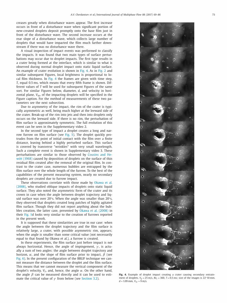
Fig. 4. Example of droplet impact creating a crater causing secondary entrain-
ment of droplets. V g = 25 m/s, Re L = 360, T = 0.5 ms; size of the images is 22 ∗10 mm.
reases greatly when disturbance waves appear. The first increase
ccurs in front of a disturbance wave when significant portion of
ew-created droplets deposit promptly onto the base film just in
ront of the disturbance wave. The second increase occurs at the
ear slope of a disturbance wave, which collects large number of
roplets that would have impacted the film much farther down-
tream if there was no disturbance wave there.
A visual inspection of impact events was performed to classify
he impacts. It was found that two main types of surface pertur-
ations may occur due to droplet impacts. The first type results in
crater being formed at the interface, which is similar to what is
bserved during normal droplet impact onto static liquid surface.
n example of crater evolution is shown in Fig. 4 . As in Fig. 2 and
imilar subsequent Figures, local brightness is proportional to lo-
al film thickness. In Fig. 4 the frames are given with time step,
, equal 0.5 ms, which means that every fifth frame is shown. Dif-
erent values of T will be used for subsequent Figures of the same
ort. For similar Figures below, diameter, d , and velocity in hori-
ontal plane, V xy , of the impacting droplets will be specified in the
igure caption. For the method of measurements of these two pa-
ameters see the next subsection.
Due to asymmetry of the impact, the rim of the crater is typi-
ally asymmetric as well, being much higher at the leeward side of
he crater. Break-up of the rim into jets and then into droplets only
ccurs on the leeward side. If there is no rim, the perturbation of
lm surface is approximately symmetric. The full evolution of this
vent can be seen in the Supplementary video 2.
In the second type of impact a droplet creates a long and nar-
ow furrow on film surface (see Fig. 5 ). The droplet quickly pro-
rudes from the point of initial contact with the film over a finite
istance, leaving behind a highly perturbed surface. This surface
s covered by transverse "wrinkles" with very small wavelength.
uch a complete event is shown in Supplementary video 3. These
erturbations are similar to those observed by Cousins and He-
itt (1968) caused by deposition of droplets on the surface of thin
esidual film created after the removal of the original film. In con-
rast to the crater case, numerous bubbles are entrapped by the
lm surface over the whole length of the furrow. To the best of the
apabilities of the present measuring system, nearly no secondary
roplets are created due to furrow impact.
These observations correlate with those made by Okawa et al.
2008) , who studied oblique impacts of droplets onto static liquid
urface. They also noted the asymmetric form of the crater and its
rown in case when the angle between droplet trajectory and liq-
id surface was over 20 °s. When the angle was smaller than 20 °s,
hey observed that droplets created long patches of highly agitated
lm surface. Though they did not report anything about the bub-
les creation, the latter case, presented by Okawa et al. (2008) in
heir Fig. 1 d looks very similar to the creation of furrows reported
n the present work.
It is supposed that these similarities are true in our case: when
he angle between the droplet trajectory and the film surface is
elatively large, a crater, with possible asymmetric rim, appears;
hen the angle is smaller than some critical value (not necessarily
qual to that found by Okawa et al.), a furrow is created.
In these experiments, the film surface just before impact is not
lways horizontal. Hence, the angle of impingement, γ , is actu-
lly a sum of two angles: the angle between droplet trajectory and
orizon, α, and the slope of film surface prior to impact, β (see
ig. 6 ). In the present configuration of the BBLIF technique we can-
ot measure the distance between the droplet and the film surface.
his means that we cannot measure the vertical component of the
roplet’s velocity, V z , and, hence, the angle α. On the other hand,
he angle β can be measured directly and it can be used to esti-
ate the critical value of γ from below (see Section 3.2 ).
d = 1.09 mm, V xy = 9 m/s.
74 A.V. Cherdantsev et al. / International Journal of Multiphase Flow 88 (2017) 69–86
Fig. 5. Example of droplet impact creating a furrow causing entrapment of bub-
bles. V g = 25 m/s, Re L = 220. T = 0.2 ms; size of the images is 28 ∗4 mm. d = 0.71 mm,
V xy = 20 m/s.
Fig. 6. Sketch showing the impact angles.
Fig. 7 . Example of droplet impact with survival of the initial droplet. V g = 30 m/s,
Re L = 220. T = 0.4 ms; size of the images is 22 ∗6.5 mm. d = 1.23 mm, V xy = 7.09 m/s.
p
t
fl
d
F
5
o
3
t
o
c
a
b
B
i
p
c
A third type of event is survival of the impacting droplet
( Fig. 7 ). An example of such an occurrence is shown in Supple-
mentary video 4. At the initial point of contact, either crater or
furrow – the latter is rarer – is created. The top part of the droplet
does not sink into the film; it continues to travel with the same
velocity while the bottom part has already stuck to the film. The
middle part of the droplet is stretched and finally ruptured (see
Section 3.5 for more details), releasing the upper part to continue
its flight. Most likely, this kind of event occurs when a droplet with
large horizontal and small vertical velocity components hits the
crest of a ripple. In the present classification the survival events
were separated from ‘normal’ craters or furrows, since in this case
art of the droplet momentum does not contribute to the film per-
urbation.
Fig. 8 shows the relative frequencies of the impact types for all
ow conditions. The frequencies are approximately the same and
o not show any distinct trend with either gas or liquid flow rate.
urrows appear more often than the others, representing about
5–60% of events, craters make 30–35% and the relative frequency
f survival events is only ∼5%.
.2. Measurements of the impact parameters
To quantify the various impact types, it is necessary to know
hose parameters which define the impact. This includes properties
f film and droplet prior to impact. As a rule, in the further pro-
essing the impact events for all gas and liquid flow rates will be
nalysed together. This approach is based on two main premises:
(1) The impact is defined by the properties of the impacting
droplet and liquid film;
(2) Scatter of properties of both film and droplet within one pair
of flow rates is much larger than the average effect of flow
rates on droplets and local film properties.
The film measurements are relatively simple and automatic,
ased on the 3D matrix of film thickness, h(x,y,t) , obtained by
BLIF method. Three quantities were extracted from this process-
ng for each impact: local average film thickness at the impact
oint, h 0 ; local slope of film surface at the impact point, β; lo-
al curvature of film surface at the impact point, h c . For an impact

A.V. Cherdantsev et al. / International Journal of Multiphase Flow 88 (2017) 69–86 75
Fig. 8. Relative frequencies of various types of impact events. Each value along ab-
scissa axis corresponds to a certain combination of flow conditions. V g = 25 m/s
(1–3); V g = 30 m/s (4–6); V g = 35 m/s (7–9). Re L = 220 (1,4,7); Re L = 360 (2,5,8);
Re L = 520 (3,6,9).
Table 1
Maximum absolute error of measurements of film properties prior to impact
for given percentage of impact events.
Percentage of impact events δh 0 , mm σβ , degrees σh c , mm
−1
40 0 .014 0 0 .014
60 0 .024 0 .24 0 .034
80 0 .04 0 .95 0 .094
90 0 .057 2 .15 0 .194
95 0 .078 4 .53 0 .298
e
t
b
f
d
s
e
s
w
i
d
o
e
c
a
t
β
n
b
v
e
a
δ
r
δ
c
a
m
e
s
t
t
m
t
t
v
a
w
s
t
i
t
0
p
s
a
t
p
i
a
p
e
β
c
o
f
i
f
t
e
p
s
t
i
f
o
o
o
t
d
m
d
e
d
v
d
s
i
s
d
d
v
vent with parameters t 0 , x 0 , y 0 , film surface was studied at a time
0 -0.2 ms in order to prevent taking into account the local peak in
rightness caused by the presence of the impacting droplet. Short
ragment of a longitudinal section of RoI at fixed y 0 , namely, h(x 0 -
x: x 0 + dx,y 0 ,t 0 -0.2 ms) was selected for processing. For the mea-
urements of h 0 and β , dx was equal 3 pixels or 0.12 mm; for
stimation of h c , dx was equal 25 pixels or 1 mm. Prior to mea-
urements, matrix h(x,y) was smoothed with 2D median filter with
indow size of 50 ∗50 pixels (2 ∗2 mm) in order to minimize the
nfluence of local perturbations of the record caused by bubbles,
roplets or optical distortions. h 0 was defined as the average value
f the processed fragment; β was defined as arctangent of the co-
fficient of the highest power in the linear interpolation of the pro-
essed fragment. Local film curvature, h c , was defined in this study
s the coefficient of the highest power in parabolic interpolation of
he fragment.
In order to characterise reliability of the measurements of h 0 ,
and h c , root-mean-square error of every single approximation,
amely, σh 0 , σβ and σh c , was recorded. Then cumulative distri-
utions of these errors were analysed to estimate the maximum
alue of error of interpolation for certain percentage of impact
vents. The errors of approximation were then transformed into
bsolute errors of measurements of β and h c as:
β = arct an ( σβ/ 2 dx ) ; δh c = 2 σh c /dx 2 .
Here δβ and δh c are absolute errors of β and h c measurements,
espectively (note that dx was different for determination δβ and
h c ). The error data are summarised in Table 1 for different per-
entage of impact events.
For the majority of impact events errors of measurements of h 0 nd β are small enough (note that the standard deviation of h 0 easurements includes physical slope of the interface and the real
rror is expected to be smaller). The error is larger for h c mea-
urements, which is most likely caused by large length over which
he interpolation was performed and higher probability of encoun-
ering optical distortions, bubbles, etc. However, the main goal of
easuring the curvature of the waves at the point of impact was
o identify whether the impact occurs at the crest of a ripple or at
he trough between the ripples. For this purpose, the sign of cur-
ature is sufficient.
The distributions of impact events by these three parameters
re given in Fig. 9 separately for each type of the impact for the
hole investigated range of flow conditions.
It can be seen from Fig. 9 a that the majority of furrows and
urvival cases occur when the film is thin, i.e. on the base film be-
ween the disturbance waves. Crater impact events are distributed
n a much wider range of h 0 values; the main part of these events
akes place on disturbance waves (i.e., for h 0 above approximately
.5 mm).
Fig. 9 b shows the distributions by the film slope prior to im-
act. All the furrow and survival events belong to the range of
lopes between −5 ̊ to 10 ̊, whilst crater events are distributed in
wide range of values. This is in agreement with the aforemen-
ioned idea on the influence of the impingement angle on the im-
act type. It is reasonable to assume that the angle α (see Fig. 6 )
s positive for the impacting droplets, and hence the impingement
ngle γ ≥β . Okawa et al. (2008) suggested that the critical im-
ingement angle is equal 20 ̊. Thus, significant portion of crater
vents belongs to the range of γ ≥20 ̊, whilst the whole range of
for furrows is below the critical value by 10–25 ̊. This is also
onsistent with the data shown in Fig. 9 a, since the slow ripples
n the base film are less steep than the disturbance waves and the
ast ripples on top of disturbance waves.
The curvature data are shown in Fig. 9 c. The majority of the
mpacts occur on surfaces with negative curvature, i.e., crests of
ast or slow ripples. This is more probable than the impact into a
rough between the ripples. The fast ripples over which the crater
vents occur have larger negative curvature than the slow rip-
les. It is interesting to note that the survival events take place at
lightly larger negative curvature than the furrows, which is consis-
ent to the explanation of the survival of droplets proposed above.
Fig. 9 d shows comparison of film thickness distribution at the
mpact points, h 0 , to the total distribution of film thickness, h , in
orm of cumulative distributions. Though the base film thickness
ccupies about 80% of all the measured values of film thickness,
nly 50% of impacts occur there. This means that relative frequency
f the impacts on the disturbance waves is about 4 times higher
han that on the base film. Thus, as it was mentioned above, the
isturbance waves are "catching" lots of droplets.
Measurements of the parameters of the impacting droplets are
ore difficult, because of large velocity and small size of the
roplets. Combined with relatively low (for this purpose) cam-
ra frequency it makes the procedure of tracking the impacting
roplets back in time complicated and risky. Nonzero transverse
elocity component of the droplets and presence of bubbles, other
roplets and optical distortions enhances the difficulties.
Therefore, measurements of droplets properties were performed
emi-manually. First, each droplet was tracked back in time start-
ng from t 0 - 0.1 ms. Its coordinates were recorded in up to 4 time
teps. The coordinates identified were used to measure longitu-
inal and transverse velocity components, V x and V y , of a single
roplet by linear approximation of x(t) and y(t) data. The absolute
elocity of impacting droplet in a horizontal plane, V xy , can be cal-

76 A.V. Cherdantsev et al. / International Journal of Multiphase Flow 88 (2017) 69–86
Fig. 9. Distributions of all the impact events by film thickness (a), slope (b) and curvature (c) prior to impact. Separate distributions for craters (1), furrows (2) and survival
events (3) are compared. Comparison of cumulative distributions of film thickness and film thickness at impact points (d).
V
w
o
s
o
p
e
w
l
p
d
d
a
T
t
a
culated as:
xy =
√
V
2 x + V
2 y .
Measurements of the sizes of droplets were performed for those
droplets whose coordinates were successfully identified for several
frames. LIF-image of a droplet is actually a sum of brightness emit-
ted by fluorescent matter contained in the droplet itself and in the
liquid film under the droplet. Two ways of separation of droplets
from the film were used. In the first method, a threshold of 15 μm
was used for binarisation of the matrix
D ( x, y ) = h ( x, y ) − M ( x, y ) ,
where M(x,y) is obtained by applying median filter with filter-
ing window 2 ∗2 mm to h(x,y) . This method was expected to work
in case of relatively small droplets. The other method was based
on assumption that the film surface does not change much over
a short time, whilst the position of droplet changes significantly.
Thus, frame difference matrix
F D ( x, y, t ) = | h ( x, y, t ) − h ( x, y, t − 0 . 1 ms ) | was binarised with the same threshold. For the largest and the
slowest droplets it is possible that the previous and current image
of the droplet will overlap, causing errors. To obtain information in
this case, the FD matrix was defined as
F D ( x, y, t ) = | h ( x, y, t ) − h ( x, y, t − 0 . 5 ms ) | was used. For each detected position of a droplet, all three meth-
ods were applied and up to 4 images from 12 images available
ere selected manually to fit two criteria: they should not contain
bvious errors in the identification of the droplet border and they
hould be the most persistent with respect to time and method
f processing. Then for the selected images, average values of the
rojection area S xy (number of pixels belonging to the droplet) of
ach droplet were recorded. Equivalent diameter of each droplet
as defined using the projection area as if the droplet was circu-
ar. Ellipticity of droplets was neglected.
For some of the droplets, identification failed. A number of ex-
lanations can be proposed:
(1) Some droplets overlapped with bubbles / other droplets /
optical distortions which made the droplet hardly distin-
guishable;
(2) Droplets with size less than the pixel size ( d < 0.04 mm) are
unlikely to be visible in the present data;
(3) Small droplets are more susceptible to the turbulent pulsa-
tions in the gas phase, so they can move chaotically and thus
be untraceable.
James et al. (1980) estimated the minimum size of traceable
roplets as 0.15 mm; we have observed a number of traceable
roplets with d = 0.12 mm, but the number of droplets with di-
meter about 0.08 mm is already very small (see Fig. 11 a below).
hus, explanation (3) is expected to be valid. Besides, it includes
he droplets mentioned in the explanation (2). Explanation (1) is
lso more likely to work for smaller droplets.

A.V. Cherdantsev et al. / International Journal of Multiphase Flow 88 (2017) 69–86 77
Fig. 10. Distributions of impacting droplets by velocity. (a) All types of impact events for three different gas velocities; (b) Normalized distributions separately for droplets
creating craters, furrows and survival events for V g = 35 m/s.
o
m
d
p
t
d
i
i
e
i
t
s
e
c
m
t
c
m
w
V
V
f
t
T
o
s
a
c
a
u
b
d
O
m
n
t
3
b
s
p
t
w
v
m
a
m
o
d
l
d
2
t
l
t
T
o
v
a
t
l
i
E
t
v
V
c
l
In total, slightly less than 500 droplets ( ∼14% of total number
f processed impact events) were not identified. Over 87% of these
issed droplets created craters and in 84% cases no secondary
roplets were observed (see Section 3.4 for details).
Accuracy of measurements of velocities and diameters of im-
acting droplets may be estimated as follows. In case of veloci-
ies the error is defined by ratio of uncertainty of identification of
roplet centres to the distance between the centres of the droplet’s
mages in neighbouring frames. Upper estimate of the numerator
s equal to droplet diameter; lower estimate of the denominator is
qual to velocity value multiplied by 0.1 (delay between the frames
n ms) which gives the distance in mm. Median value of such es-
imation gives 15% error, which increases for the largest and the
lowest droplets. However, in real experiments this error is sev-
ral times smaller for two reasons. First, the centre of a droplet
ould be identified much more precisely, and real error in nu-
erator could be estimated as 2–3 pixels or 0.1 mm. Second, for
he majority of the droplets, 4 consecutive time frames were pro-
essed together, giving three non-independent measurements. This
akes denominator three times larger. The error calculated this
ay makes 1% for the fastest droplets with V xy = 35 m/s; 2% for
xy = 15 m/s and maximum of 15% for the slowest droplets with
xy = 2 m/s. Absolute error is roughly constant ( ∼0.3 m/s) for dif-
erent velocities of the droplets.
Numerous sources of error of measurements of droplet diame-
er using BBLIF method were analysed by Alekseenko et al. (2014a) .
hese authors used RoI consisting of only one line of pixels
riented longitudinally with spatial resolution of 0.2 mm/pixel,
ampling frequency of 50 kHz and exposure of time 2 μs. They
nalysed:
• error of discretisation, which was random but rather large (up
to 10%) of their resolution; • error of misalignment, when non-central part of a droplet ap-
peared in their RoI , leading to systematic underestimation of
droplet size by 20–25%; • error caused by refraction of exciting laser light on curvilinear
surface of spherical and elliptical droplets, which was shown to
be negligible; • error of blurring of droplet images due to the finite exposure
time, which was shown to be negligible; • error caused by refraction of fluorescent light on ripples, lead-
ing to systematic overestimation by 5–10% for the range of gas
velocities used in the present experiments.
In the present experiments, the discretisation error was signifi-
antly smaller because the spatial resolution is 5 times better and
lso due to three-dimensional measurements. The latter still gave
s a discrete number of possible droplet diameters, but the step
etween the neighbouring discrete values decreased with droplet
iameter. E.g., for d = 0.2 mm this step was about 5 μm or 2.5%.
ther source of random error was due to wrong results of auto-
atic separation between the droplets and the film. This error was
ot completely eliminated, but it was minimised by the visual con-
rol procedure described above.
The misalignment error is essentially irrelevant for the present
D-measurements. Considerations on negligibility of error caused
y the refraction on droplets are still valid for the present mea-
urements. Exposure time was 20 times smaller in the present ex-
eriments. Error due to refraction on ripples remains significant,
hough it is expected to be lower in the present case since we
ere dealing only with impacting droplets, which are, as a rule,
ery close to the interface.
To summarise, we expect that random error of droplet diameter
easurements does not exceed 10% for the droplets of d = 0.2 mm
nd is much lower for larger droplets. Besides, systematic overesti-
ation of droplet diameter by 5–10% is possible due to refraction
n ripples with negative curvature.
Fig. 10 (a) shows distributions of impacting droplets by V xy for
ifferent gas velocities (bin width is 2 m/s). The data on different
iquid flow rates are united in these distributions. The velocities of
roplets are distributed in a wide range starting from the velocity
–3 times larger than that of disturbance waves (1–2 m/s) and up
o the superficial gas velocities. Though the sample size is not very
arge, an observation can be made that distributions tend to have
wo peaks: one at the lowest and one at the largest velocity values.
he first peak is related to large number of droplets falling back
n film surface soon after being entrained due to initial downward
elocity component; such droplets do not live long enough to be
ccelerated by the gas drag force. The second peak is related to
he upper velocity limitation: all the droplets that managed to live
ong enough to reach maximum velocity are ‘gathered’ here.
Fig. 10 (b) shows the velocity distributions for droplets, creat-
ng impacts of different types, for one gas velocity value of 35 m/s.
ach distribution is normalized by the total number of impacts of
his type. All the three types are distributed in a wide range of
elocities and it is difficult to pick out any significant influence of
xy on impact type. It could only be said that at the lowest V xy
reation of craters is more probable; this is reasonable since with
ow V xy the angle α will be larger at the same V z component.

78 A.V. Cherdantsev et al. / International Journal of Multiphase Flow 88 (2017) 69–86
Fig. 11. (a) Normalised distributions of all impacting droplets by diameter for the
whole sample. (b) Distribution of impacting droplets by both diameter and velocity,
V g = 35 m/s.
l
s
b
c
i
n
o
s
v
3
w
p
a
d
s
h
o
e
i
w
v
t
e
i
d
s
d
h
p
b
g
I
u
c
n
fi
a
a
b
t
d
T
i
r
p
r
c
x
q
a
p
F
h
t
o
e
The distributions of all the impacting droplets by diameter is
shown in Fig. 11 (a), separately for furrows, craters and survivals.
Bin width is 40 μm. It can be seen that the main amount of
droplets belongs to the range of diameters between 0.1 and 1 mm;
occasional droplets with size up to 2 mm were observed, but
their frequency of appearance is very small. Size distributions of
droplets creating craters and furrows are of similar shape, though
the distribution of the ‘craters’ is slightly shifted towards smaller
droplets. If we take into account that for over 400 droplets creat-
ing craters the size was not measured and that these droplets are
expected to have small size, the difference between the ‘craters’
and ‘furrows’ distributions is expected to be much stronger. This is
quite reasonable since the droplet should be large enough to con-
serve some amount of liquid beyond the point of initial contact
and to be deformed during the furrowing process. The surviving
droplets are also characterised by relatively large size. The expla-
nation is the same in this case: the droplet should be large enough
to undergo deformation and splitting into two parts.
Fig. 11 (b) shows graphical representation of the simultaneous
distribution of all the droplets at V g = 35 m/s by diameter and ve-
ocity. This number of events in each 2D-bin is given in logarithmic
cale; white colour corresponds to the maximum observed num-
er of droplets in the whole distribution (equal 45), whereas black
orresponds to absence of droplets in the bin. In general, veloc-
ty of the droplets decreases with diameter, since larger droplets
eed more time to be accelerated by the drag force. Probability
f encountering large-diameter droplets with high velocity is low,
ince they require much time to be accelerated to large values of
elocity.
.3. Furrows and bubbles entrapment
When a droplet creates a furrow, the furrow grows in length
ith velocity close to that of the droplet. After a short time the
rotrusion of furrow ceases and the decay of surface perturbations
nd elimination of portion of the entrapped bubbles is observed.
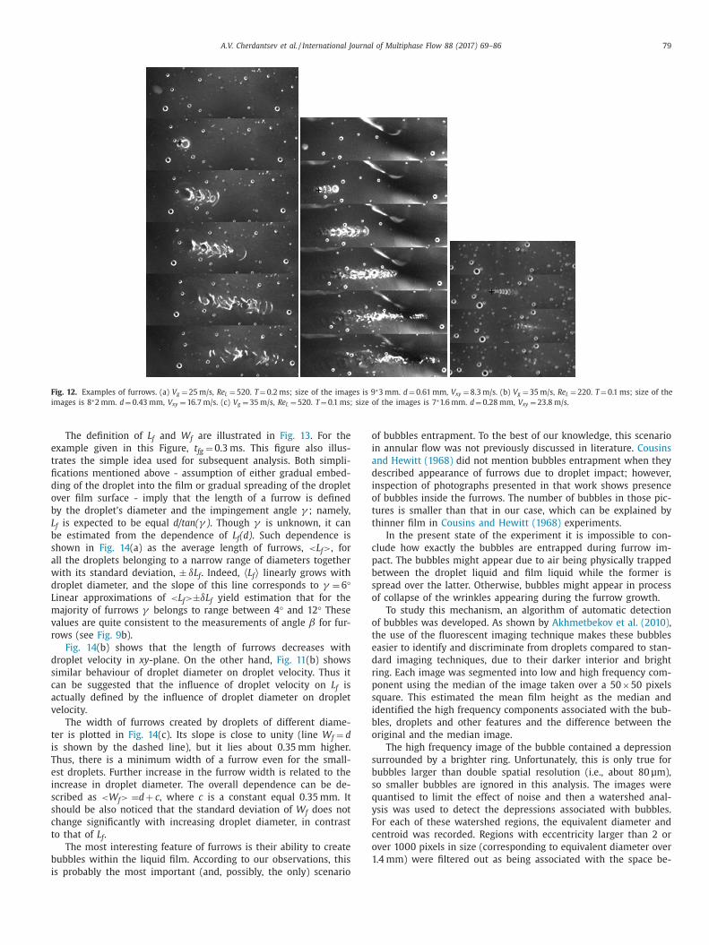
During the first part of furrow growth stage the impacting
roplet is still distinguishable; closer to the end of the growth
tage is disappears. The surface beneath the protruding droplet is
ighly perturbed. It is covered with small-wavelength ‘wrinkles’
riented orthogonally to the droplet’s trajectory and curving at the
dges. Fig. 12 shows examples of the wrinkles for different veloc-
ties of the droplets. In the model of Watanabe et al. (2008) it
as supposed that these wrinkles appear due to creation of several
ortex rings around the impacting droplet. Temporal resolution of
he present experiments is not high enough to study inception and
volution of these wrinkles and check if the model interpretation
s correct. We can only state that the wavelength of the wrinkles
ecreases with the velocity of the droplet. This seems reasonable
ince destabilising effect of larger shear stress induced by a faster
roplet should be compensated by stronger surface tension force,
ence, smaller radius of curvature of the wrinkles. Thus, it is also
ossible that the wrinkles appear due to Kelvin-Helmholtz insta-
ility induced by the shear induced by the droplet.
The maximum width of a furrow occurs in the middle and it
radually decreases towards the beginning and the end of a furrow.
t is obvious that interaction between the liquid droplets and liq-
id film is very complex, and its complete understanding requires
omplicated modelling. However, it is possible to perform prelimi-
ary experimental analysis of furrow creation using strong simpli-
cations. Two "extreme" simplifications could be made: 1) droplet
cts as a solid body, gradually embedding into the film; 2) film
cts as a solid wall, and the droplet is spread over its surface. In
oth cases the shape of the furrow would be the same as it is in
he experiments: the local width of the furrow behaves in accor-
ance with the projection area of the droplet in horizontal plane.
he bottom and top of the droplet, interacting to the film surface
n the beginning and in the end of furrow, respectively, are nar-
ower than the middle part.
In order to characterize the shape of furrows, the main three
arameters of each furrow were measured. The length of each fur-
ow, L f , was defined as the distance between the point of primary
ontact and the end of the furrow. This quantity was measured in
-y plane. Time of the furrow growth, t fg , was defined as time re-
uired for a furrow to reach the maximum length. To measure the
verage width of perturbed area, W f , area of furrow existence was
rocessed as follows. Auxiliary matrix F(x,y) was created as:
( x, y ) =
1
t f g − t 0
∣∣∣∣∣t f g ∑
t= t 0 ( h ( x, y, t ) − M ( x, y, t ) )
∣∣∣∣∣Here M(x,y,t) is the result of application of 2D median filter to
(x,y,t) with window 2 ∗2 mm. The area occupied by furrow was
hen identified by finding the values of F(x,y) larger than thresh-
ld value proportional to the median value of F(x,y) . Then W f was
stimated as the average width of this area over its length.
A.V. Cherdantsev et al. / International Journal of Multiphase Flow 88 (2017) 69–86 79
Fig. 12. Examples of furrows. (a) V g = 25 m/s, Re L = 520. T = 0.2 ms; size of the images is 9 ∗3 mm. d = 0.61 mm, V xy = 8.3 m/s. (b) V g = 35 m/s, Re L = 220. T = 0.1 ms; size of the
images is 8 ∗2 mm. d = 0.43 mm, V xy = 16.7 m/s. (c) V g = 35 m/s, Re L = 520. T = 0.1 ms; size of the images is 7 ∗1.6 mm. d = 0.28 mm, V xy = 23.8 m/s.
e
t
fi
d
o
b
L
b
s
a
w
d
L
m
v
r
d
s
c
a
v
t
i
T
e
i
s
s
c
t
b
i
o
i
a
d
i
o
t
t
c
p
b
s
o
o
t
e
d
r
p
s
i
b
o
s
b
s
q
y
F
c
o
1
The definition of L f and W f are illustrated in Fig. 13 . For the
xample given in this Figure, t fg = 0.3 ms. This figure also illus-
rates the simple idea used for subsequent analysis. Both simpli-
cations mentioned above - assumption of either gradual embed-
ing of the droplet into the film or gradual spreading of the droplet
ver film surface - imply that the length of a furrow is defined
y the droplet’s diameter and the impingement angle γ ; namely,
f is expected to be equal d/tan( γ ) . Though γ is unknown, it can
e estimated from the dependence of L f (d) . Such dependence is
hown in Fig. 14 (a) as the average length of furrows, < L f > , for
ll the droplets belonging to a narrow range of diameters together
ith its standard deviation, ± δL f . Indeed, 〈 L f 〉 linearly grows with
roplet diameter, and the slope of this line corresponds to γ = 6 °inear approximations of < L f > ±δL f yield estimation that for the
ajority of furrows γ belongs to range between 4 ° and 12 ° These
alues are quite consistent to the measurements of angle β for fur-
ows (see Fig. 9 b).
Fig. 14 (b) shows that the length of furrows decreases with
roplet velocity in xy -plane. On the other hand, Fig. 11 (b) shows
imilar behaviour of droplet diameter on droplet velocity. Thus it
an be suggested that the influence of droplet velocity on L f is
ctually defined by the influence of droplet diameter on droplet
elocity.
The width of furrows created by droplets of different diame-
er is plotted in Fig. 14 (c). Its slope is close to unity (line W f = d
s shown by the dashed line), but it lies about 0.35 mm higher.
hus, there is a minimum width of a furrow even for the small-
st droplets. Further increase in the furrow width is related to the
ncrease in droplet diameter. The overall dependence can be de-
cribed as < W f > = d + c , where c is a constant equal 0.35 mm. It
hould be also noticed that the standard deviation of W f does not
hange significantly with increasing droplet diameter, in contrast
o that of L f .
The most interesting feature of furrows is their ability to create
ubbles within the liquid film. According to our observations, this
s probably the most important (and, possibly, the only) scenario
f bubbles entrapment. To the best of our knowledge, this scenario
n annular flow was not previously discussed in literature. Cousins
nd Hewitt (1968) did not mention bubbles entrapment when they
escribed appearance of furrows due to droplet impact; however,
nspection of photographs presented in that work shows presence
f bubbles inside the furrows. The number of bubbles in those pic-
ures is smaller than that in our case, which can be explained by
hinner film in Cousins and Hewitt (1968) experiments.
In the present state of the experiment it is impossible to con-
lude how exactly the bubbles are entrapped during furrow im-
act. The bubbles might appear due to air being physically trapped
etween the droplet liquid and film liquid while the former is
pread over the latter. Otherwise, bubbles might appear in process
f collapse of the wrinkles appearing during the furrow growth.
To study this mechanism, an algorithm of automatic detection
f bubbles was developed. As shown by Akhmetbekov et al. (2010) ,
he use of the fluorescent imaging technique makes these bubbles
asier to identify and discriminate from droplets compared to stan-
ard imaging techniques, due to their darker interior and bright
ing. Each image was segmented into low and high frequency com-
onent using the median of the image taken over a 50 ×50 pixels
quare. This estimated the mean film height as the median and
dentified the high frequency components associated with the bub-
les, droplets and other features and the difference between the
riginal and the median image.
The high frequency image of the bubble contained a depression
urrounded by a brighter ring. Unfortunately, this is only true for
ubbles larger than double spatial resolution (i.e., about 80 μm),
o smaller bubbles are ignored in this analysis. The images were
uantised to limit the effect of noise and then a watershed anal-
sis was used to detect the depressions associated with bubbles.
or each of these watershed regions, the equivalent diameter and
entroid was recorded. Regions with eccentricity larger than 2 or
ver 10 0 0 pixels in size (corresponding to equivalent diameter over
.4 mm) were filtered out as being associated with the space be-

80 A.V. Cherdantsev et al. / International Journal of Multiphase Flow 88 (2017) 69–86
Fig. 13. Definition of the main parameters of a furrow.
m
o
p
m
n
m
0
t
a
b
3
s
w
s
i
a
d
b
s
t
p
s
F
i
a
i
o
o
o
K
c
a
p
t
c
w
i
V
l
l
i
m
i
(
d
t
a
s
m
a
V
tween bubbles or optical distortions. This clearly identified most
of the bubbles larger than 2 pixels in size.
In the present work, the algorithm was applied to the areas of
existence of furrows; temporal evolution behaviour of number and
size of bubbles within this area was studied.
Fig. 15 a shows number of bubbles within the area of furrow
existence ( L f ∗2W f ) for three long (each with t fg = 0.9 ms) furrows.
Number of bubbles that existed in this area prior to impact was
subtracted from N(t) . It can be seen that the new bubbles ap-
pear when the furrow grows; after this, some bubbles disappear.
The time moment at which the maximum number of bubbles is
observed roughly corresponds to the time of furrow growth, t fg ( Fig. 15 b). Approximation curves in Fig. 15 (a) were created in the
form:
N bub =
2 N 0 t f g t
t 2 + t 2 f g
where N 0 is the maximum number of bubbles within this approxi-
mation. It is most likely that the bubbles collapse due to relaxation
of strong shear induced by the furrowing droplet. A portion of the
bubbles survive in this process.
To study the effect of droplets properties on bubbles entrap-
ent, number of entrapped bubbles was normalized over the area
ccupied by a furrow. This area was taken as 2 W f L f and it is ex-
ected to grow as d 2 (see Figs. 14 (a,c)). Fig. 16 shows that this nor-
alised number of bubbles does not show any distinct dependence
either on droplet diameter (a) nor on droplet velocity (b). Maxi-
um density of bubbles created by an average furrow is of order
.9 bubbles per square millimetre; it gradually decreases with time
o the value of about 0.15 at 3 t fg . Absolute number of bubbles cre-
ted by a furrowing droplet is then defined by the area occupied
y furrow.
.4. Craters and secondary entrainment
Secondary droplets are produced when the rim at the leeward
ide of the crater is broken into jets. The number of jets increases
ith the size of the crater. For example, the rather large crater
hown in Fig. 4 is broken into three jets. Secondary entrainment
ncreases the number of droplets in the gas core and decreases the
verage size of the droplets, since in this case one large droplet
isappears and a number of smaller droplets are created from
oth film and droplet material. However, the detailed analysis has
hown that in the majority of cases of crater impacts (86% in
he present experiment) no secondary droplets detectable by the
resent measuring system were observed.
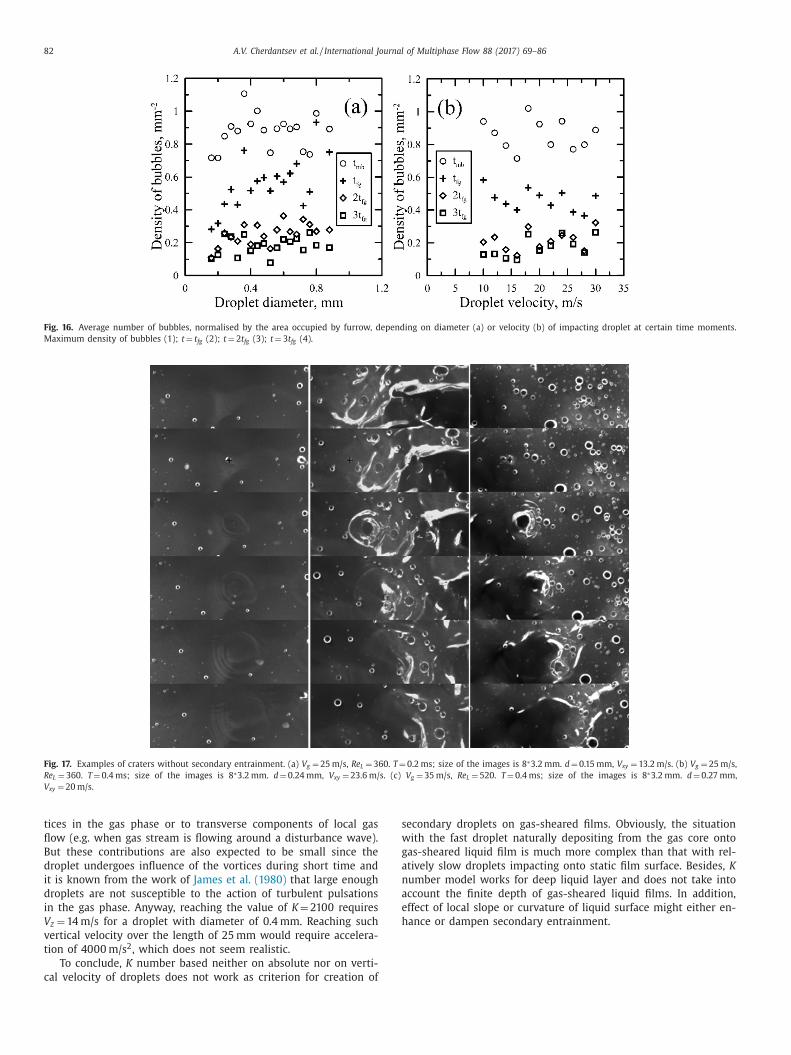
Example of a crater impact without secondary entrainment is
hown in Fig. 17 (compare to Fig. 4 ). Quite often (as shown in
ig. 17 a) even a crater is not formed; only a circular capillary wave
s created around the point of contact. In the other cases, the crater
ppears ( Fig. 17 b-c), but its rim is not broken into droplets. The
mpacting droplets are hardly detectable at these images because
f their small size and high velocity.
Okawa et al. (2008) used impact number K as a criterion of sec-
ndary droplets creation. This parameter is constructed as function
f droplet Weber number, We, and Ohnesorge number, Oh :
= W eO h
−0 . 4 ; W e =
ρdV
2 d
σ; Oh =
μ√
ρdσ.
Here ρ is liquid density, σ - surface tension, μ - dynamic vis-
osity.
Okawa et al. used the critical value of K = 2100 as limit for cre-
tion of secondary droplets. Absolute velocity of a droplet in x-z
lane was used as V d . It was shown that this value fits better than
hat based on vertical velocity component, V z .
To test this approach, the K number was determined for 764
rater impacts without secondary droplets and 164 crater impacts
ith secondary droplets. Fig. 18 a shows the distribution of ‘crater’
mpacts by K number based on the horizontal velocity of droplet,
xy . Only 16% of droplets impacting without secondary droplets be-
ong to the range of K ≤ 2100 and for the rest of cases K was much
arger, reaching values of 30,0 0 0 ( Fig. 18 (a)). Thus, K based on hor-
zontal velocity does not work as criterion for secondary entrain-
ent. Moreover, the distributions by horizontal velocity are nearly
dentical for both presence and absence of secondary droplets
Fig. 18 b). On the contrary, certain difference exists between the
istributions by droplet diameter ( Fig. 18 c). Taking into account
hat for 437 impacts without secondary droplets the droplet size
nd velocity were not measured quite likely due to small size of
uch droplets (see Section 3.2 ), the difference is expected to be
uch stronger.
Absolute velocity used by Okawa et al. is obviously expressed
s:
=
√
V
2 xy + V
2 z .

A.V. Cherdantsev et al. / International Journal of Multiphase Flow 88 (2017) 69–86 81
Fig. 14. Average value and standard deviation of length of furrows, created by droplets from narrow range of diameter (a) and velocity (b). (c) Dependence of furrow width
on droplet diameter.
Fig. 15. a) Examples of temporal evolution of the number of bubbles created due to ‘furrow’ impacts. b) Time of maximum number of bubbles vs time of furrow growth.
w
a
t
t
c
a
Thus, V will be always larger than V xy and it also would not
ork as a criterion of splash. We should note that this criterion
lso did not work with the data of Okawa et al. (2008) for angles
o liquid surface below 30 °
pPossible alternative is to construct the K number based on ver-
ical velocity V z . In our case V z should not reach large values. The
ontribution of gravity into V z is limited to 0.7 m/s (the case when
droplet falls from the ceiling of the duct to its bottom). The other
ossible sources contributing to V z are related to action of vor-
82 A.V. Cherdantsev et al. / International Journal of Multiphase Flow 88 (2017) 69–86
Fig. 16. Average number of bubbles, normalised by the area occupied by furrow, depending on diameter (a) or velocity (b) of impacting droplet at certain time moments.
Maximum density of bubbles (1); t = t fg (2); t = 2 t fg (3); t = 3 t fg (4).
Fig. 17. Examples of craters without secondary entrainment. (a) V g = 25 m/s, Re L = 360. T = 0.2 ms; size of the images is 8 ∗3.2 mm. d = 0.15 mm, V xy = 13.2 m/s. (b) V g = 25 m/s,
Re L = 360. T = 0.4 ms; size of the images is 8 ∗3.2 mm. d = 0.24 mm, V xy = 23.6 m/s. (c) V g = 35 m/s, Re L = 520. T = 0.4 ms; size of the images is 8 ∗3.2 mm. d = 0.27 mm,
V xy = 20 m/s.
s
w
g
a
n
a
e
h
tices in the gas phase or to transverse components of local gas
flow (e.g. when gas stream is flowing around a disturbance wave).
But these contributions are also expected to be small since the
droplet undergoes influence of the vortices during short time and
it is known from the work of James et al. (1980) that large enough
droplets are not susceptible to the action of turbulent pulsations
in the gas phase. Anyway, reaching the value of K = 2100 requires
V z = 14 m/s for a droplet with diameter of 0.4 mm. Reaching such
vertical velocity over the length of 25 mm would require accelera-
tion of 40 0 0 m/s 2 , which does not seem realistic.
To conclude, K number based neither on absolute nor on verti-
cal velocity of droplets does not work as criterion for creation of
econdary droplets on gas-sheared films. Obviously, the situation
ith the fast droplet naturally depositing from the gas core onto
as-sheared liquid film is much more complex than that with rel-
tively slow droplets impacting onto static film surface. Besides, K
umber model works for deep liquid layer and does not take into
ccount the finite depth of gas-sheared liquid films. In addition,
ffect of local slope or curvature of liquid surface might either en-
ance or dampen secondary entrainment.

A.V. Cherdantsev et al. / International Journal of Multiphase Flow 88 (2017) 69–86 83
Fig. 18. Comparison of normalized distributions of crater impacts with and without secondary droplets by K number (a), horizontal velocity (b) and diameter (c) of impacting
droplet.
3
o
A
r
s
u
F
f
c
t
d
u
s
i
f
a
b
i
c
o
o
D
e
fi
o
a
t
s
i
a
S
l
b
u
w
t
o
b
s
t
p
t
i
p
o
a
m
.5. Survival of impacting droplet
In about 5% of impact events partial or even complete survival
f impacting droplet was observed. Such event was observed by
lekseenko et al. (2014a) during investigation of droplet trajecto-
ies in one longitudinal section of the duct: it was found that in
uch cases the spatiotemporal trajectory of the droplet is contin-
ed after interaction with the film without change in velocity; see
ig. 9 (bottom right) in that paper. Both droplet and film are de-
ormed during the interaction. At the initial point of contact either
rater or furrow – the latter is much rarer – is created. Deforma-
ion of the droplet is rather complex. Below several scenarios of
roplet deformation are considered.
In case 1, the whole droplet survives after interaction with liq-
id film ( Fig. 19 a). From the point of contact a capillary wave
preads over film surface, either in circular manner or sideways
f the area of contact is long enough. The droplet itself is also af-
ected by the interaction: its aspect ratio undergoes temporal vari-
tion due to oscillations induced by the interaction. It should also
e noted that this scenario is realised at relatively low velocities of
mpacting droplets, of order of 6 m/s or less.
In case 2 the major part of droplet continues its flight after the
ontact, but for a while the droplet remains connected to the point
f contact by a thin liquid filament ( Fig. 19 b). As the droplet moves
n, the filament is stretched and finally broken into tiny droplets.
escription of the mechanisms of a ligament rupture can be found,
.g., in Dumochel et al. (2015) , see Figs. 3 and 6 in that paper. The
b
lm surface in this case is perturbed much stronger with formation
f either a crater or a furrow.
In case 3 a liquid sheet is formed between the area of contact
nd the survived droplet (see Fig. 20 and also Fig. 7 ). Due to ac-
ion of liquid sheet, the droplet is deformed into an arrowhead
hape. While the sheet is being stretched, tiny jets are formed on
ts edges (see also Fig. 2 in Dumouchel et al. 2015 ). Finally, the jets
nd the remaining part of liquid sheet are broken into droplets.
urviving part of impacting droplet in this case carries much less
iquid than the original droplet did.
It is most likely that which particular scenario occurs is defined
y the degree of embedding of the impacting droplet into the liq-
id film. In case 1 the droplet only slightly touches the film surface
ithout adhering to it. It is even possible that there is no real con-
act between the film and the droplet in this case due to presence
f very thin air layer between them. In the other two cases the
ottom of a droplet adheres to film surface, embedding into it to
ome depth and making either a crater or a furrow. Meanwhile, the
op part of the droplet continues its travel. As a result, the middle
art of the droplet is stretched between the point of contact and
he top part of the droplet. The shape into which the middle part
s deformed depends on depth of embedding.
As it can be seen from Figs. 7, 19 and 20 , survival event takes
lace when the contact point is located at a crest of a ripple. Quite
bviously, vertical component of droplet’s velocity is small in such
case. If such a droplet did not impact onto the crest of a ripple,
aterial of the top part of the droplet would be spread over the
ase film surface, making a furrow. But, since the point of contact

84 A.V. Cherdantsev et al. / International Journal of Multiphase Flow 88 (2017) 69–86
Fig. 19. Examples of survival of impacting droplet. (a) Total survival. V g = 30 m/s, Re L = 220. T = 0.2 ms; size of the images is 10 ∗3.2 mm. d = 0.39 mm, V xy = 5.6 m/s. (b) Partial
survival with formation of a liquid filament. V g = 30 m/s, Re L = 360. T = 0.2 ms; size of the images is 16 ∗3.2 mm. d = 0.78 mm, V xy = 10 m/s.
s
o
b
s
i
d
t
b
4
t
p
t
o
g
fl
e
a
s
a
d
t
t
is located above the base film thickness level, the top part of the
droplet flies in the air and has a chance to last longer. Cousins and
Hewitt (1968) mentioned that the depositing droplets "underwent
series of bounces of low trajectory before being finally absorbed into
the film" . The process of impact with droplet survival may indeed
look as bouncing in the cine film images.
Other examples of droplet bouncing were described by
Che et al. (2015) for slow droplets falling onto 45 ° inclined film.
Nonetheless, in the present work, for the majority of the cases ad-
hesion and deformation of the impacting droplet is clearly seen.
The term "bouncing" might be applicable only to the case 1, but
this cannot be confirmed in the present experiments.
Survival events have much similarity to the crater events with
creation of secondary droplets (or splash). Indeed, in both cases
a droplet creates a crater on film surface and it leads to creation
of a number of droplets with different size. Thus, the two events
can be easily mixed up during the observations. The best criterion
for distinction between the two events is that the velocity of the
impacting droplet nearly does not change in the survival case. In
the case of splash certain amount of time is required for the crater
evolution, formation of the rim and rim breaking. In particular, it
is very likely that the ‘secondary entrainment’ events shown in
Fig. 7 in Pham et al. (2014) actually demonstrate the survival of the
impacting droplet. In both cases the droplet hits crest of a ripple
and its top part does not lose velocity despite being connected to
the point of contact. Besides, ligament break-up entrainment event
mhown in Fig. 6 (c) in Pham et al. might actually be a survival event
f case 2 ( Fig. 19 b in the present paper). The important difference
etween the splash and survival events is that in case of splash the
econdary droplets are mainly created from the film liquid, whilst
n the case of survival they are mostly created from the impacting
roplet material. This distinction may be important in some prac-
ical applications in which the droplets are different from the film
y physical or chemical properties, temperature, etc.
. Discussion and conclusions
Impacts of droplets, previously entrained from film surface into
he gas core and deposited back onto film surface, are studied ex-
erimentally using BBLIF-technique. To the best of our knowledge,
his is the first systematic study of impact classification, morphol-
gy and outcome for the droplets, “naturally” introduced into the
as core and thus for the situation really taking place in annular
ow occurring in various industrial equipment. The main differ-
nces between the impacts of “natural” droplets in annular flow
nd the impacts of artificial droplets in model experiments con-
ist in large velocity and small impingement angle of the droplets
nd in interaction with gas-sheared wavy film covered with both
isturbance waves and ripples.
It was shown that the impacts can be classified into two main
ypes based on the manner of film surface perturbation. The two
ypes of perturbation were called ‘craters’ and ‘furrows’. The for-
er looks as a circular crater with possible asymmetric rim ap-

A.V. Cherdantsev et al. / International Journal of Multiphase Flow 88 (2017) 69–86 85
Fig. 20. Rupture of droplet with formation of liquid sheet (a) V g = 25 m/s, Re L = 220. T = 0.1 ms; size of the images is 14 ∗3.2 mm. d = 1.05 mm, V xy = 17.6 m/s. (b) V g = 35 m/s,
Re L = 360. T = 0.1 ms; size of the images is 8 ∗3.2 mm. d = 0.61 mm, V xy = 9.8 m/s.
p
o
l
e
t
i
q
a
s
r
e
d
l
w
F
c
s
d
a
i
o
i
a
1
i
d
c
b
c
p
b
t
t
a
w
d
s
s
T
s
a
l
a
earing on its leeward side, which is very similar to perturbation
f liquid surface by droplets falling under large angles onto still
iquid surface. The latter makes long and narrow perturbation cov-
red with transverse wrinkles. Based on comparison to the litera-
ure studies of oblique impact onto static film and on indirect ev-
dence from the present measurements, it was assumed that the
uantity determining realisation of particular impact type is the
ngle between the droplet trajectory and the local slope of film
urface. From the measurements of film slope and length of fur-
ow the critical angle of impingement for furrow formation was
stimated to be about 20 °, which is in agreement to the literature
ata.
Probability of furrow creation due to impact is about twice
arger than that of crater creation; this ratio does not change much
ithin the flow conditions range used in the present experiments.
urrows were shown to occur mainly on the base film, whereas
raters are much more likely to occur at the disturbance waves. Be-
ides, the total number of impacts increases significantly in front of
isturbance waves (due to prompt deposition of newborn droplets)
nd on the rear slopes of disturbance waves (since these elevations
n the film thickness are able to ‘catch’ the droplets that would
therwise impact farther downstream).
The most important difference between the ‘crater’ and ‘furrow’
mpacts consists in outcome of the impact. For the crater case, cre-
tion of secondary droplets was observed in part of cases (about
5% of all registered crater events). The crater rim in such a case
s broken into a number of jets, and each jet is in turn broken into
roplets.
The criterion of appearance of secondary entrainment is un-
lear; the widely used K number does not work here neither being
ased on absolute velocity of impacting droplet nor on its vertical
omponent.
In contrast to the crater impacts, outcome of the furrow im-
acts is mainly the bubbles entrapped by the liquid film. The bub-
les are created when the droplet protrudes along film surface; af-
er the furrow formation, a portion of the bubbles collapse, but
he rest survive and travel inside the film. Number of bubbles cre-
ted by a furrow is mainly defined by the area of film perturbation,
hich is in turn mainly defined by the diameter of the impacting
roplet.
In about 5% of impact events part of the impacting droplet
urvived the impact. Such situation occurs when a droplet with
mall vertical velocity component touches crest of a ripple wave.
he middle part of the droplet is strongly deformed while being
tretched between the bottom part which had adhered to the film
nd the top part which continues its flight with its original ve-
ocity. The middle part can be deformed into either a liquid fil-
ment or liquid sheet depending on depth to which the droplet

86 A.V. Cherdantsev et al. / International Journal of Multiphase Flow 88 (2017) 69–86
C
C
D
H
L
O
P
P
P
S
S
T
T
V
W
W
embeds into the film. Finally, the middle part is broken into small
droplets, whilst the top part of the droplet continues its travel. This
event may be considered as a specific case of secondary entrain-
ment in which the secondary droplets are created from the droplet
material.
These results are expected to bring some clarification into the
available knowledge of droplets deposition in annular gas-liquid
flow and to be useful for creation and validation of new models
of mass exchange between the gas core and the liquid film. Partic-
ular moments that could be taken into account to improve exist-
ing models of droplets deposition in annular flow are: non-uniform
deposition of droplets in different parts of film surface; influence
of the region of deposition on impact type and outcome; probabil-
ity of secondary entrainment; change of droplet size distribution
due to secondary entrainment and survival events; role of droplet
impacts in process of bubbles entrapment by liquid film.
Acknowledgements
The work was supported by the UK EPSRC [grant MEMPHIS
EP/K003976/1 ]; Royal Society and Russian Foundation for Basic Re-
search [grant 15-58-10059-KO_a ].
Supplementary materials
Supplementary material associated with this article can be
found, in the online version, at doi:10.1016/j.ijmultiphaseflow.2016.
09.015 .
References
Akhmetbekov, Y.K. , Alekseenko, S.V. , Dulin, V.M. , Markovich, D.M. , Pervunin, K.S. ,2010. Planar fluorescence for round bubble imaging and its application for the
study of an axisymmetric two-phase jet. Exp. Fluids 48, 615–629 . Alekseenko, S.V , Cherdantsev, A.V. , Heinz, O.M. , Kharlamov, S.M. , Markovich, D.M. ,
2014b. Analysis of spatial and temporal evolution of disturbance waves and rip-ples in annular gas–liquid flow. Int. J. Multiphase Flow 67, 122–134 .
Alekseenko, S.V. , Antipin, V.A. , Cherdantsev, A.V. , Kharlamov, S.M. , Markovich, D.M. ,
2008. Investigation of waves interaction in annular gas-liquid flow usinghigh-speed fluorescent visualization technique. Microgravity Sci. Technol. 20,
271–275 . Alekseenko, S.V. , Cherdantsev, A.V. , Markovich, D.M. , Rabusov, A.V. , 2014a. Investiga-
tion of droplets entrainment and deposition in annular flow using LIF technique.Atomization Sprays 24, 193–222 .
Alghoul, S. , Eastwick, C. , Hann, D. , 2011. Droplet impact on shear-driven liquid films.
Atomization Sprays 21, 833–846 . Azzopardi, B.J. , 1983. Mechanisms of Entrainment in Annular Two-Phase Flow.
UKAEA Report AERE-R 11068 . Azzopardi, B.J. , 1987. Observations of drop motion in horizontal annular flow. Chem.
Eng. Sci. 42 (8), 2059–2062 . Azzopardi, B.J. , 1997. Drops in annular two-phase flow. Int. J. Multiphase Flow 23,
1–53 .
Azzopardi, B.J. , Teixeira, J.C.F. , 1994. Detailed measurements of vertical annulartwo-phase flow—part I: drop velocities and sizes. J. Fluids Eng. 116 (4), 792–795 .
Azzopardi, B.J. , Zaidi, S.H. , 1998. Drop sizes and velocities in annular two-phase flow.14th Annual Conference on Liquid Atomisation and Spray Systems, Manchester,
U.K., July 6-8, 1998 . Badie, S. , 20 0 0. Horizontal Stratifying/Annular Gas-Liquid Flow Ph.D. thesis. Imperial
College, London . Bisighini, A. , Cossali, G.E. , Tropea, C. , Roisman, I.V. , 2010. Crater evolution after the
impact of a drop onto a semi-infinite liquid target. Phys. Rev. E - Statist. Non-
linear Soft Matter Phys. 82 . Che, Z. , Deygas, A. , Matar, O.K. , 2015. Impact of droplets on inclined flowing liquid
films. Phys. Rev. E 92, 023032 . Cherdantsev, A.V. , Hann, D.B. , Azzopardi, B.J. , 2014. Study of gas-sheared liquid film
in horizontal rectangular duct using high-speed LIF technique: three-dimen-sional wavy structure and its relation to liquid entrainment. Int. J. Multiphase
Flow 67, 52–64 .
ioncolini, A. , Thome, J.R. , 2010. Prediction of the entrained liquid fraction in verti-cal annular gas–liquid two-phase flow. Int. J. Multiphase Flow 36, 293–302 .
ousins, L.B. , Hewitt, G.F. , 1968. Liquid Phase Mass Transfer in Annular Two-PhaseFlow: Droplet Deposition and Liquid Entrainment. UKAEA report AERE - R 5657 .
umouchel, C. , Blaisot, J.-B. , Bouche, E. , Ménard, T. , Vu, T.-T. , 2015. Multi-scale anal-ysis of atomizing liquid ligaments. Int. J. Multiphase Flow 73, 251–263 .
Fore, L.B. , Dukler, A.E. , 1995. The distribution of drop size and velocity in gas-liquidannular flow. Int. J. Multiphase Flow 21, 137–149 .
ann, D.B. , Cherdantsev, A.V. , Mitchell, A. , McCarthy, I.N. , Hewakandamby, B.N. , Sim-
mons, K. , 2016. A study of droplet impact on static films using the BB-LIF tech-nique. Exp. Fluids 57 (4), 1–12 .
James, P.W. , Hewitt, G.F. , Whalley, P.B. , 1980. Droplet motion in two-phase flow. In:ANS/ASME Topical Meeting on Reactor Thermal-Hydraulics; Saratoga, NY, USA;
9 - 12 Oct 1980, pp. 1484–1503 . Lagubeau, G. , Fontelos, M.A . , Josserand, C. , Maurel, A . , Pagneux, V. , Petitjeans, P. ,
2012. Spreading dynamics of drop impacts. J. Fluid Mech. 713, 50–60 .
eman, G.W. , Agostini, M. , Andreussi, P. , 1985. Tracer analysis of developingtwo-phase annular flow. PCH Phys. Chem. Hydrodyn. 6 (1/2), 223–237 .
Leneweit, G. , Koehler, R. , Roesner, K.G. , Schaffer, G. , 2005. Regimes of drop morphol-ogy in oblique impact on deep fluids. J. Fluid Mech 543, 303–331 .
guz, H.N. , Prosperetti, A. , 1990. Bubble entrainment by the impact of drops onliquid surfaces. J. Fluid Mech. 219, 143–179 .
Okawa, T. , Shiraishi, T. , Mori, T. , 2008. Effect of impingement angle on the outcome
of single water drop impact onto a plane water surface. Exp. Fluids 44, 331–339 .an, L. , Hanratty, T.J. , 2002. Correlation of entrainment for annular flow in vertical
pipes. Int. J. Multiphase Flow 28, 363–384 . ham, S.H. , Kawara, Z. , Yokomine, T. , Kunugi, T. , 2014. Detailed observations of wavy
interface behaviors of annular two-phase flow on rod bundle geometry. Int. J.Multiphase Flow 59, 135–144 .
itton, E. , Ciandri, P. , Margarone, M. , Andreussi, P. , 2014. An experimental study of
stratified–dispersed flow in horizontal pipes. Int. J. Multiphase Flow 67, 92–103 .amenfink, W. , Elsäßer, A. , Dullenkopf, K. , Wittig, C. , 1999. Droplet interaction with
shear-driven liquid films: analysis of deposition and secondary droplet charac-teristics. Int. J. Heat Fluid Flow 20 (5), 462–469 .
awant, P. , Ishii, M. , Mori, M. , 2008. Droplet entrainment correlation in vertical up-ward co-current annular two-phase flow. Nucl. Eng. Des. 238, 1342–1352 .
horoddsen, S.T. , Etoh, T.G. , Takehara, K. , 2003. Air entrainment under an impacting
drop. J. Fluid Mech. 478, 125–134 . horoddsen, S.T. , Etoh, T.G. , Takehara, K. , 2008. High-speed imaging of drops and
bubbles. Ann. Rev. Fluid Mech. 40, 257–285 . an Hinsberg, N.P. , Budakli, M. , Gohler, S. , Berberovich, E. , Roisman, I.V. , Gam-
baryan-Roisman, T. , Tropea, C. , Stephan, P. , 2010. Dynamics of the cavity andthe surface film for impingements of single drops on liquid films of various
thicknesses. J. Coll. Interface Sci. 350, 336–343 .
atanabe, Y. , Saruwatari, A. , Ingram, D.M. , 2008. Free-surface flows under impactingdroplets. J. Comp. Phys. 227, 2344–2365 .
oodmansee, D.E. , Hanratty, T.J. , 1969. Mechanism for the removal of droplets froma liquid surface by a parallel air flow. Chem. Eng. Sci. 24, 299–307 .
Worthington, A.M. , 1877. On drops. Nature 16, 165–166 . Zhao, H. , Ecault, R. , Dorao, C.A. , Munkejord, S.T. , 2011. Splashing of water droplets
on a tilted flowing liquid film. DIPSI Workshop on Droplet Impact Phenomena& Spray Investigation. May 27, 2011 . Bergamo, Italy.