
International Journal of Heat and Mass...
12
Thermal–hydraulic performance of a novel shell-and-tube oil cooler with multi-fields synergy analysis Jie Yang, Lei Ma, Jiaju Liu, Wei Liu ⇑ School of Energy and Power Engineering, Huazhong University of Science and Technology, Wuhan 430074, China article info Article history: Received 4 January 2014 Received in revised form 4 March 2014 Accepted 6 June 2014 Available online 3 July 2014 Keywords: Oil cooler Shell-and-tube heat exchanger Spiral tubes Multi-field synergy principle abstract In the present paper, a novel shell-and-tube heat exchanger is proposed for the application of oil cooler. It is numerically investigated compared to a rod baffles shell-and-tube heat exchanger using the commer- cial software FLUENT 6.3 and GAMBIT 2.3. The results of heat transfer, flow characteristics, and compre- hensive performance are analyzed for both tube-side and shell-side with verifications of correlations and experimental apparatus. For tube-side, the novel heat exchanger demonstrates evidently excellent over- all performance; while for shell-side, the novel heat exchanger illustrates slightly lower comprehensive performance than the rod baffles one. The path lines, pressure field, and temperature field are analyzed and the multi-fields synergy principle is adopted to evaluate the synergy extent between velocity, tem- perature, and pressure fields. Ó 2014 Elsevier Ltd. All rights reserved. 1. Introduction Shell-and-tube heat exchangers (STHXs) are widely used in the petro-chemical industry, manufacturing industry, food preserva- tion, electrical power production and energy conservation systems, due to their structural simplicity, relatively low cost and design adaptability. According to Master and co-workers, they account for more than 35–40% of the heat exchangers used in global heat transfer processes [1]. The conventional heat exchangers with seg- mental baffles (STHXsSB) are one of the most commonly used exchangers in the practical application. However, they have the disadvantages of high pumping power, fouling problems in the dead zones, and induction vibration of tube bundles [2]. Therefore, it is of great significance to propose new heat exchangers in order to overcome the above-mentioned drawbacks. Lots of novel structures [3–29] have been suggested to enhance heat transfer, reduce power consumption and increase cost- effectiveness for the past decades. Among the those new heat exchangers, the main concept is altering the shell-side flow from zigzag pattern to longitudinal or helical pattern to avoid the impact of tube bundles and reduce the relaminarization and recirculation flow. As a result, this flow pattern variation increases heat transfer area, compresses heat exchanger, and improves cost-efficiency. Although the open literature is replete of multifarious novel heat exchangers, it is difficult to apply one heat exchanger for all fields since each design contains certain disadvantages. Therefore inves- tigating new heat transfer enhancement techniques and proposing novel design to increase thermal–hydraulic performance are still in demands. Experiments can provide highly reliable measurements of thermal–hydraulic performance; however, experiments can be extremely expensive and time-consuming compared to computa- tional fluid dynamics (CFD). For very complex flows, such as those prevailing in the rod-baffle shell-and-tube heat exchanger, select- ing an appropriate modeling approach can be difficult. There are complex tradeoffs between accuracy and computational expense. For example, a heat exchanger with 500 heat transfer tubes and 10 baffles requires at least 150 million computational cells to resolve the geometry. So far there are four main modeling approaches used for numerical simulations: the unit model [30,31,20], the periodic model [32,33], the porous model [34–37,21] and the whole model [38–40]. Recently Yang et al. [41] summarized the four modeling approaches, conducted a comparison of four different models on numerical accuracy, grid system size, computational period, and restriction, and provided an approach on selecting the most appropriate model for the practical situation. So far, the performance evaluation criteria (PEC) [42,43], effi- ciency evaluation criterion (EEC) [44,45], and multi-fields synergy principle [46–53] have been proposed to evaluate performance and effectiveness. They all have been successfully utilized to ana- lyze thermal–hydraulic performance. Through a wide literature survey, it is noticed that little work about its application on the whole model simulation of a shell-and-tube heat exchanger have http://dx.doi.org/10.1016/j.ijheatmasstransfer.2014.06.015 0017-9310/Ó 2014 Elsevier Ltd. All rights reserved. ⇑ Corresponding author. Tel.: +86 27 87541998; fax: +86 27 87540724. E-mail address: [email protected] (W. Liu). International Journal of Heat and Mass Transfer 77 (2014) 928–939 Contents lists available at ScienceDirect International Journal of Heat and Mass Transfer journal homepage: www.elsevier.com/locate/ijhmt
Transcript of International Journal of Heat and Mass...

International Journal of Heat and Mass Transfer 77 (2014) 928–939
Contents lists available at ScienceDirect
International Journal of Heat and Mass Transfer
journal homepage: www.elsevier .com/locate / i jhmt
Thermal–hydraulic performance of a novel shell-and-tube oil coolerwith multi-fields synergy analysis
http://dx.doi.org/10.1016/j.ijheatmasstransfer.2014.06.0150017-9310/� 2014 Elsevier Ltd. All rights reserved.
⇑ Corresponding author. Tel.: +86 27 87541998; fax: +86 27 87540724.E-mail address: [email protected] (W. Liu).
Jie Yang, Lei Ma, Jiaju Liu, Wei Liu ⇑School of Energy and Power Engineering, Huazhong University of Science and Technology, Wuhan 430074, China
a r t i c l e i n f o a b s t r a c t
Article history:Received 4 January 2014Received in revised form 4 March 2014Accepted 6 June 2014Available online 3 July 2014
Keywords:Oil coolerShell-and-tube heat exchangerSpiral tubesMulti-field synergy principle
In the present paper, a novel shell-and-tube heat exchanger is proposed for the application of oil cooler. Itis numerically investigated compared to a rod baffles shell-and-tube heat exchanger using the commer-cial software FLUENT 6.3 and GAMBIT 2.3. The results of heat transfer, flow characteristics, and compre-hensive performance are analyzed for both tube-side and shell-side with verifications of correlations andexperimental apparatus. For tube-side, the novel heat exchanger demonstrates evidently excellent over-all performance; while for shell-side, the novel heat exchanger illustrates slightly lower comprehensiveperformance than the rod baffles one. The path lines, pressure field, and temperature field are analyzedand the multi-fields synergy principle is adopted to evaluate the synergy extent between velocity, tem-perature, and pressure fields.
� 2014 Elsevier Ltd. All rights reserved.
1. Introduction
Shell-and-tube heat exchangers (STHXs) are widely used in thepetro-chemical industry, manufacturing industry, food preserva-tion, electrical power production and energy conservation systems,due to their structural simplicity, relatively low cost and designadaptability. According to Master and co-workers, they accountfor more than 35–40% of the heat exchangers used in global heattransfer processes [1]. The conventional heat exchangers with seg-mental baffles (STHXsSB) are one of the most commonly usedexchangers in the practical application. However, they have thedisadvantages of high pumping power, fouling problems in thedead zones, and induction vibration of tube bundles [2]. Therefore,it is of great significance to propose new heat exchangers in orderto overcome the above-mentioned drawbacks.
Lots of novel structures [3–29] have been suggested to enhanceheat transfer, reduce power consumption and increase cost-effectiveness for the past decades. Among the those new heatexchangers, the main concept is altering the shell-side flow fromzigzag pattern to longitudinal or helical pattern to avoid the impactof tube bundles and reduce the relaminarization and recirculationflow. As a result, this flow pattern variation increases heat transferarea, compresses heat exchanger, and improves cost-efficiency.Although the open literature is replete of multifarious novel heatexchangers, it is difficult to apply one heat exchanger for all fields
since each design contains certain disadvantages. Therefore inves-tigating new heat transfer enhancement techniques and proposingnovel design to increase thermal–hydraulic performance are still indemands.
Experiments can provide highly reliable measurements ofthermal–hydraulic performance; however, experiments can beextremely expensive and time-consuming compared to computa-tional fluid dynamics (CFD). For very complex flows, such as thoseprevailing in the rod-baffle shell-and-tube heat exchanger, select-ing an appropriate modeling approach can be difficult. There arecomplex tradeoffs between accuracy and computational expense.For example, a heat exchanger with 500 heat transfer tubes and 10baffles requires at least 150 million computational cells to resolvethe geometry. So far there are four main modeling approaches usedfor numerical simulations: the unit model [30,31,20], the periodicmodel [32,33], the porous model [34–37,21] and the whole model[38–40]. Recently Yang et al. [41] summarized the four modelingapproaches, conducted a comparison of four different models onnumerical accuracy, grid system size, computational period, andrestriction, and provided an approach on selecting the mostappropriate model for the practical situation.
So far, the performance evaluation criteria (PEC) [42,43], effi-ciency evaluation criterion (EEC) [44,45], and multi-fields synergyprinciple [46–53] have been proposed to evaluate performanceand effectiveness. They all have been successfully utilized to ana-lyze thermal–hydraulic performance. Through a wide literaturesurvey, it is noticed that little work about its application on thewhole model simulation of a shell-and-tube heat exchanger have

Fig. 1. Schematic diagram of the eccentric spiral tube: (a) the tube centerline; (b)the spiral tube; (c) the front view.
Nomenclature
Ah hydraulic area (m2)A heat transfer area (m2)cp specific heat capacity (kJ kg�1 K�1)C1e empirical constant (–)C2e empirical constant (–)Cl empirical constant (–)Di tube inner diameter (m)Do tube outer diameter (m)Ds shell inner diameter (m)Dh hydraulic diameter (m)f friction coefficient (–)Gk producing item of k by average velocity gradient
(kg m�1 s�3)h heat transfer coefficient (W m�2 K�1)i, j, k component on x, y, z coordinates (–)k turbulent kinetic energy (m2 s�2)L baffle pitch (mm)L0 baffle distance from head (mm)Lt tube length (m)n tube quantity (–)Nu Nusselt number (–)PEC performance evaluation criteria (–)Ph hydraulic length (m)ps pitch of the helix curve (mm)p pressure (Pa)DP pressure drop (Pa)
Q heat transfer power (W)Re Reynolds number (–)S eccentric distance (mm)T temperature (K)u inlet average velocity (m s�1)U flow velocity of fluid (m s�1)r, h, h cylindrical coordinates (–)
Greek symbolsq fluid density (kg m�3)k thermal conductivity (W m�1 K�1)l dynamic viscosity (kg m�1 s�1)e turbulent dissipation rate (m2 s�3)rk Prandtl numbers corresponded to k (–)re Prandtl numbers corresponded to e (–)b synergy angle (�)h synergy angle (�)
Subscriptsave average valuee enhanced heat exchangerp primary heat exchangerw wall
J. Yang et al. / International Journal of Heat and Mass Transfer 77 (2014) 928–939 929
been reported in open literature since these procedures consumetoo much computational resources. In this paper, a novel oil cooleris proposed to provide an alternative solution for industrial design-ers. 3-D numerical simulations of the heat exchanger for bothtube-side and shell-side are developed. The thermal–hydraulicperformances of tube-side and shell-side are investigated andPEC is used to analyze the results. The present work also extendsthe application of multi-fields synergy principle on the wholemodel simulation of shell-and-tube heat exchanger, thus fillingthe gap in open literature.
2. Model formulation
2.1. Geometric introduction
Recently our research group invented a novel heat transfer tubecalled eccentric spiral tube as shown in Fig. 1. Each cross section ofthe tube is a circle. The centerline of tube is a helix curve and itsequation in cylindrical coordinate system is expressed as follows:
rðtÞ ¼sin t � s 2 � ðk� 1Þ � p 6 t 6 2kp
4
s 2kp4 6 t 6 6kp
4
� sin t � s 6kp4 6 t 6 2kp
9>=>;k 2 Z
8><>:
hðtÞ ¼ thðtÞ ¼ ps � t
8>>>>>><>>>>>>:
ð1Þ
where r, h, h are the coordinates in cylindrical coordinate system; sstand for the eccentric distance of the tube centerline; ps stands forthe pitch of the helix curve; Do and Di represent the outer and innerdiameter of tube cross-section, respectively. In the present work, Do
and Di is set as 16 and 14 mm, p is set as 40 mm, s is set as 2.5 mm.Motivated from the rod baffle heat exchanger [6–9] and twisted
tubes heat exchanger [10–14], our research group proposed a novelshell-and-tube heat exchanger as shown in Figs. 2 and 3. The origi-nal plain tubes in the conventional STHXsSB are replaced by this
novel heat transfer tubes. This alignment results in heat transfertubes contacting at many points along the length of tube in bundle.So all tubes are tightly braced and there exists no tube movementduring working condition. The spiral tubes are assembled into sucha bundle that there is no need to install any baffles (segmental,helical, orifice, rod, trefoil-hole, or flower baffles) or supportingparts (ring) between each tube in the heat exchanger. Therefore,it is expected that this shell-and-tube heat exchanger with spiraltubes (STHXsST) has the advantages of higher thermal–hydraulicperformance, higher thermal effectiveness, tube bundle vibrationelimination, and lower fouling due to its unique structure in bothtube-side and shell-side. As one of the most outstanding inventionsin the field of shell-and-tube heat exchanger, the shell-and-tubeheat exchanger with rod baffles (STHXsRB), rather than STHXsSB,is taken as the reference group in order to demonstrate the noveltyand improvement of the new oil cooler. The optimized geometricparameters [54,55] are adopted in the present work as presentedin Table 1. For STHXsRB and STHXsST, all geometric parametersincluding shell diameter, shell length, tube number, inlet and out-

1 3
8 11
62
109
4 5 7
Fig. 2. 2-D diagram of the shell-and-tube heat exchanger with spiral tubes: 1. fluidcavity; 2. tube sheet; 3. shell-side inlet; 4. contacting points; 5. spiral tube; 6. shell-side outlet; 7. fluid cavity; 8. tube-side outlet; 9. shell wall; 10. tube sheet; 11. tube-side inlet.
Fig. 3. 3-D diagram of the shell-and-tube heat exchanger with spiral tubes: 1. shell-side inlet; 2. shell-side outlet; 3. contacting points; 4. spiral tube; 5. shell-side outerwall.
Table 1Structural parameter of shell-and-tube heat exchanger.
Shell diameter (Ds) 144 mmTube outer diameter 16 mmTube inner diameter 14 mmTube effective length 1000 mmTube pitch 22 mmTube number 21Baffle number 7Baffle thickness 5 mmBaffle pitch (L) 120 mmBaffle distance from head (L0) 140 mmInlet and outlet nozzles 50 mmTube arrangement Non-staggered placement
930 J. Yang et al. / International Journal of Heat and Mass Transfer 77 (2014) 928–939
let nozzles are identical except the parameters involving configura-tion of spiral tube.
2.2. Governing equations, grid generation and boundary conditions
2.2.1. Governing equationsIn the paper, the novel shell-and-tube heat exchanger is used as
oil cooler, thus the fluid for tube-side is oil in laminar flow andfluid for shell-side is water in turbulent flow. The conservationequations for both fluids are presented in the tensor form in theCartesian coordinate system as the flows are steady and the fluidsare incompressible [56,57].
Continuity equation:
@uj
@xj¼ 0 ð2Þ
Momentum equation:
q � @ðuiujÞ@xj
¼ � @pi
@xiþ @
@xjl @ui
@xjþ @uj
@xi
� �� �ð3Þ
Energy equation:
q � @ðujTÞ@xj
¼ @
@xj
kcp
@T@xj
� �ð4Þ
where q is fluid density, k is thermal conductivity, cp is specificheat capacity, p is pressure, l is dynamic viscosity, T is tempera-ture. As the fluid for shell-side is in turbulent flow, the regular k–e model is adopted:
Turbulent kinetic energy:
q � @ðkuiÞ@xi
¼ @
@xjlþ lt
rk
� �@k@xj
�� �þ Gk � qe ð5Þ
Turbulent energy dissipation:
q � @ðeuiÞ@xi
¼ @
@xjlþ lt
ee
� �@e@xj
�� �þ C1ee
kGk � C2eq
e2
kð6Þ
where k is turbulent kinetic energy, e is turbulent dissipationrate, Gk is producing term of turbulent kinetic energy generatedby mean velocity gradient, C1e and C2e are empirical constants, rk
and re are Prandtl numbers corresponding to turbulent kineticenergy and turbulent dissipation rate, lt is defined as follows[56,57]:
lt ¼ qClk2
eð7Þ
where Cl = 0.09, C1e = 1.44, C2e = 1.92, rk = 1.0, re = 1.3 and Gk isdefined as follows [56,57]:
Gk ¼ lt@ui
@xjþ @uj
@xi
� �@ui
@xjð8Þ
2.2.2. Grid generationThe geometric modeling and grid generation procedures were
carried out with commercial CFD preprocessor GAMBIT 2.3. The3D model is presented as in Fig. 3. According to the method givenby Yang [41], the whole modeling approach is utilized for shell-side computational calculations as it provides the highest accuracyand real flow conditions while the other three modelingapproaches cannot be used. The grid independence test was com-pleted for each model. Taking the STHXsRB model as an example,five different grid systems with 5.0 � 106, 1.1 � 107, 1.7 � 107,2.5 � 107 and 3.3 � 107 cells were adopted for calculation. The dif-ferences in heat transfer coefficient and friction coefficientbetween the third and fourth model are around 7% and the differ-ences between the fourth and fifth model are around 2%. Thus, tak-ing numerical resource cost and solution accuracy intoconsideration, the fourth model with 2.5 � 106 grid system wasadopted. The model of STHXsRB was discretized with hexahedralmeshes for the most flow region and with tetrahedral meshes forthe baffle region, while the model of STHXsST was discretized withall hexahedral meshes. After the grid independence test, the finalcell numbers for STHXsRB and STHXsST are 2.5 � 107 and1.6 � 107, respectively. The meshes of heat exchanger models areshown in Figs. 4 and 5. For tube-side, hexahedral cells wereadopted to mesh the internal space for the spiral tube. Local gridrefinement was applied in the boundary layers. After grid indepen-dence test, the final cells number is around 2.5 � 106. The meshesof the spiral tube are shown in Fig. 6. All numerical calculations are

Table 2Thermo-physical properties of fluid in oil cooler heat exchanger.
Parameters Shell-side (water) Tube-side (oil)
cp (J/kg K) 4182 2270.1l (kg/m s) 0.001003 0.0095q (kg/m3) 998.2 826.1k (W/m K) 0.6 0.132
Fig. 4. Grid system of STHXsRB: (a) nozzles part; (b) front view; (c) rod baffle.
Fig. 5. Grid system of STHXsST: (a) nozzles part; (b) front view.
Fig. 6. Grid system of the spiral tube.
J. Yang et al. / International Journal of Heat and Mass Transfer 77 (2014) 928–939 931
performed on a workstation with 20 dual-core CPUs and 160 GBRAM. Overall, it takes approximately 210 h to complete all calcula-tions (not include the synergy angle calculations).
2.2.3. Boundary conditionsThe commercial CFD software Fluent 6.3 was adopted for all the
numerical simulations. The 3D, double-precision, pressure-basedsolver was used. The conservation equations are discretized witha finite volume formulation. The standard wall function methodis adopted for the near-wall region, and a non-slip boundary con-dition is adopted on all solid surfaces. For shell-side the surfacesof solid regions are set as adiabatic because the impact caused bythermal conduction of the baffles can be neglected. The velocity-inlet boundary condition is applied for the inlet since for incom-pressible fluid the velocity-inlet boundary condition is equal tomass-flow-inlet boundary condition in Fluent, and the outflowboundary condition is applied for the outlet since the pressurefor outlet is not given. The temperatures of tube inner and outerwalls are set as constant and their values are taken from the aver-age wall temperature determined in the experiments. The shellwall is set as adiabatic. The two-order upwind difference schemeis applied, and the SIMPLE algorithm is adopted for the couplingbetween pressure and velocity field; the two-order upwind differ-ence scheme is applied for energy and momentum computation,and the standard difference scheme is used for the pressure. Theother setting parameters adopt the default settings according tothe user’s guide in Fluent. The working fluids for shell-side and
tube-side are set as water and oil and the corresponding parame-ters are listed in Table 2. The following assumptions are made tosimplify numerical simulations for both tube-side and shell-side:the thermal-physical properties of the fluids such as q, l, cp, kare constant; the working fluids are isotropic, Newtonian, incom-pressible, and continuous; the effect of gravity is negligible andviscous heating and thermal radiation are ignored.
2.3. Data reduction
The Reynolds number is expressed as follows:
Re ¼ q � u � Dh
lð9Þ
where u is the fluid velocity, and Dh is the hydraulic diameter. Fortube-side Dh is the inner diameter of tube, while for shell-side Dh
is expressed as follows:
Dh ¼4Ah
Ph¼ p � D2
s � p � n � D2o
p � Ds þ p � n � Doð10Þ
where Ah is the hydraulic area and Ph is the hydraulic length. Ds andDo are inner diameter of shell and outer diameter of tube. n is thetube quantity. The Nusselt number is expressed as follows:
Nu ¼ h � Dh
kfð11Þ
where kf is thermal conductivity and h is the convective heat trans-fer coefficient expressed as follows:
h ¼ QA � ðTw � TaveÞ
ð12Þ
where Q is heat transfer power, A is heat transfer area, Tw is walltemperature and Tave is average temperature for the working fluid.The friction factor is calculated as
f ¼ 2DhDPqLtu2 ð13Þ
where DP is pressure drop, Lt is tube length. The performance evalu-ation criteria are defined as following to measure the comprehensiveperformance [42,43]:
PEC ¼ Nue=Nup
ðfe=fpÞ1=3 ð14Þ

Fig. 7. Comparison between the simulation results and correlation results of plain tube: (a) Nu; (b) f.
Fig. 9. Comparison between the simulation results and experimental results of shell-side for rod baffles heat exchanger [41].
Fig. 8. Schematic diagram for experimental system.
932 J. Yang et al. / International Journal of Heat and Mass Transfer 77 (2014) 928–939

Fig. 10. The path lines in the spiral tube.
J. Yang et al. / International Journal of Heat and Mass Transfer 77 (2014) 928–939 933
where the subscripts e stands for the enhanced heat exchanger andp stands for the primary heat exchanger.
3. Model validation
3.1. Tube-side
To verify the numerical modeling approach, the same modelingmethod was adopted for plain tube in laminar flow. The computa-tional results were compared to the empirical correlations in
Fig. 12. Comparison between STHXsRB and STHXsST fo
Fig. 11. Numerical results for spiral tube: (a) thermal–hydraul
literature [58–60]. For the laminar flow in a tube with entranceeffect, the correlation in reference [58] was used to calculateNusselt number expressed as follows:
Nu ¼ 3:66þ 0:065ðD=LÞReDPr
1þ 0:04½ðD=LÞReDPr�2=3 ð15Þ
and the Sieder–Tate correlation in Ref. [59] was also used tocalculate Nusselt number expressed as follows:
Nu ¼ 1:86Ref Prf
l=d
� �13 gf
gw
� �0:14
ð16Þ
For the friction coefficient calculation, the H.L. Langhaar plot corre-lation was used to calculate friction coefficient. More information ofthe plot could be found in [60]. As shown in Fig. 7, it is seen that theCFD results and correlation outcomes are in good agreement. There-fore it is safely concluded that the tube-side model has a reliableaccuracy.
3.2. Shell-side
In order to verify the precision of shell-side whole modelingapproach on predicting heat transfer and pressure drop, experi-mental method was used. The schematic for the experimental sys-tem is presented in Fig. 8. The system consists of three loops, whichare hot water loop, cooling water loop and refrigerating loop. Thehot water loop contains a 58 kW electrical heater, water tank,hot water pump, flow meters and tube-side of a heat exchanger.The cooling water loop contains the water side of a plate heat
r shell-side: (a) Nusselt number; (b) pressure drop.
ic performance; (b) performance evaluation criteria value.

Fig. 13. The PEC value of STHXsST for different Reynolds number.
934 J. Yang et al. / International Journal of Heat and Mass Transfer 77 (2014) 928–939
exchanger, water tank, cold water pump, flow meters and theshell-side of a heat exchanger. The refrigerating loop contains a58 kW refrigerating unit device, pump and the refrigerant side of
Fig. 14. Path lines in shell-side when Re = 14,000: (a) rod baf
a plate heat exchanger. When the experiment is in steady opera-tion, the heat generated by electrical heater is transferred fromthe hot water to the cold water in the heat exchanger. Then thethermal power in cooling water loop transfers heat from water torefrigerant at the plate heat exchanger. Finally, heat is rejected toambient air. The volume flow rates for cold and hot fluids are mea-sured using four rotary flow meters. The temperature of the fluidsis measured using four K-type thermal couples that are insertedinto holes at the hot fluid inlet, hot fluid outlet, cold fluid inlet,and cold fluid outlet. The pressure drops between inlet and outletfor the shell and the tube-side are measured using the two pres-sure drop transmitters. All data of temperature and pressure differ-ence are transmitted in the PC system and automatically recordedthrough a data acquisition system. Due to the length limitation ofcontext, more information regarding uncertainty analysis, datareduction and experimental apparatus could be found in [41] forreader’s convenience.
Fig. 9 provides a comparison between numerical and experi-mental results for shell-side average Nusselt number and pressuredrop for rod baffles heat exchanger [41]. It is observed that the
fle heat exchanger; (b) heat exchanger with spiral tubes.
J. Yang et al. / International Journal of Heat and Mass Transfer 77 (2014) 928–939 935
numerical results are in excellent agreement with experimentalresults. For most of the data points, the differences between com-putational and experimental results are less than 8%. The maxi-mum discrepancies are about 10.8% for Nusselt number and12.4% for pressure drop. Therefore it is decided that the wholemodeling approach has a high precision on predicting thermal–hydraulic performance.
4. Analysis of thermal–hydraulic performance and discussion
To more clearly elucidate the underlying mechanism, the pathlines in spiral tube are presented in Fig. 10. It is clearly seen thatvortex has been formed near the wall of spiral tube, while the fluidin the core region can still maintain a straight bulk flow. The ther-mal–hydraulic performance and PEC are presented in Fig. 11.Fig. 11(a) shows that the Nusselt numbers of both spiral tubeand plain tube increase with the increment of Reynolds number,while the former increases more rapidly. So the Nusselt numberdifference between spiral tube and plain tube increases with theincrement of Reynolds number. Fig. 11(a) also depicts that all thefriction coefficients decrease with the increment of the Reynolds
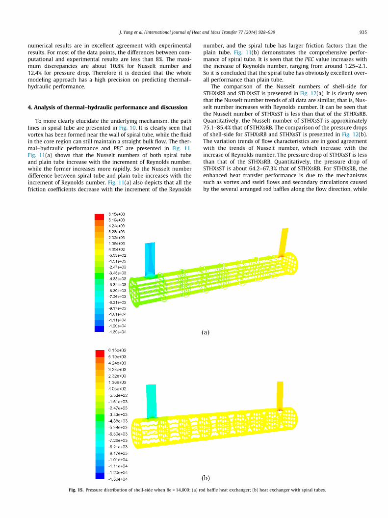
Fig. 15. Pressure distribution of shell-side when Re = 14,000: (a) ro
number, and the spiral tube has larger friction factors than theplain tube. Fig. 11(b) demonstrates the comprehensive perfor-mance of spiral tube. It is seen that the PEC value increases withthe increase of Reynolds number, ranging from around 1.25–2.1.So it is concluded that the spiral tube has obviously excellent over-all performance than plain tube.
The comparison of the Nusselt numbers of shell-side forSTHXsRB and STHXsST is presented in Fig. 12(a). It is clearly seenthat the Nusselt number trends of all data are similar, that is, Nus-selt number increases with Reynolds number. It can be seen thatthe Nusselt number of STHXsST is less than that of the STHXsRB.Quantitatively, the Nusselt number of STHXsST is approximately75.1–85.4% that of STHXsRB. The comparison of the pressure dropsof shell-side for STHXsRB and STHXsST is presented in Fig. 12(b).The variation trends of flow characteristics are in good agreementwith the trends of Nusselt number, which increase with theincrease of Reynolds number. The pressure drop of STHXsST is lessthan that of the STHXsRB. Quantitatively, the pressure drop ofSTHXsST is about 64.2–67.3% that of STHXsRB. For STHXsRB, theenhanced heat transfer performance is due to the mechanismssuch as vortex and swirl flows and secondary circulations causedby the several arranged rod baffles along the flow direction, while
d baffle heat exchanger; (b) heat exchanger with spiral tubes.

Fig. 16. Temperature distribution of shell-side when Re = 14,000: (a) rod baffle heat exchanger; (b) heat exchanger with spiral tubes.
936 J. Yang et al. / International Journal of Heat and Mass Transfer 77 (2014) 928–939
for STHXsST the heat transfer is mainly due to the disruption andreattachment of boundary layers as the spiral tubes have the fea-ture of curve surface. The relation of PEC value versus Reynoldsnumber for STHXsST is presented in Fig. 13 in comparison withthe primary heat exchanger, i.e. the rod baffle heat exchanger. Itis observed that all PEC values of STHXsST exceed 0.9, revealingthat the comprehensive performance of STHXsST is around ten per-cent less than that of STHXsRB according to performance evalua-tion criteria.
For the traditional shell-and-tube heat exchangers with seg-mental baffles, the shell-side flow is zigzag pattern. This flow pat-tern achieves enhancing heat transfer and pressure dropdramatically, but it yields many practical issues. It is well estab-lished from the open literature that altering the shell-side flowfrom zigzag pattern to longitudinal or helical pattern is a verypromising design technique for shell-and-tube heat exchangersto overcome those real problems. It is easily expected that the shellflows in both STHXsRB and STHXsST are longitudinal, but the flowmechanisms are various, which will be validated in the followingcontext. In conclusion, the shell-side overall performance ofSTHXsST is slightly lower than that of STHXsRB. But the tube-sideoverall performance is greatly better than that of STHXsRB. It also
should be noticed that due to the unique configuration of spiraltube the heat transfer area of STHXsST is larger than that ofSTHXsRB, which results in larger area-volume ratio.
The path lines of shell-side for both heat exchangers when Rey-nolds number is 14,000 are shown in Fig. 14. It can be clearly seenthat both flows are longitudinal and the flow in the shell-and-tubeheat exchanger with spiral tubes is smoother than that of the rodbaffles heat exchanger. Accompanying with the supporting rodbaffles, the fluid flow is tortuous. The variation of shell-side fluidpressure is shown in Fig. 15. The streamwise decrease of fluid pres-sure is easily seen. It can be also observed that the pressure gradi-ent for the shell-and-tube heat exchanger with spiral tubes ismuch smaller than that of the rod baffles heat exchanger. It is alsoseen that the pressure distribution for the novel oil cooler is moreuniform than that of the old one. The variation of shell-side fluidtemperature is shown in Fig. 16. It is seen that the temperaturefiled for the novel oil cooler is well-distributed along the shell-side.
5. Multi-fields synergy principle analysis
Guo [46], Tao [47], and Liu [48–53] proposed the multi-fieldssynergy principle and introduced several synergy angles, claiming

4000 8000 12000 16000 2000078
80
82
84
86
88
β / (°)
STHXsRBSTHXsST
Re4000 8000 12000 16000 20000
44
46
48
50
52
54
θ / (°)
STHXsRBSTHXsST
Re
(a) (b)
Fig. 17. Comparison of synergy angle b and h between STHXsRB and STHXsST.
J. Yang et al. / International Journal of Heat and Mass Transfer 77 (2014) 928–939 937
that they are relevant with the relations between velocity, temper-ature and pressure fields. The dot product of dimensionless veloc-ity and temperature gradient in 2-D energy synergy equation canbe expressed as [46]:
U � rT ¼ jUjjrTj cos b ð17Þ
Thus the synergy angle b is defined as follows:
b ¼ arccosU � rTjUjjrTj ð18Þ
The synergy angle b between the temperature and velocityfields indicates the heat transfer enhancement extent for the noveltechniques compared to the original heat transfer technique. Liuextended the synergy principles and proposed other synergyangles. The dot product of dimensionless velocity and pressure gra-dient in 2-D energy synergy equation can be expressed as [53]:
U � ð�rpÞ ¼ jUjj � rpj cos h ð19Þ
Thus the synergy angle h is defined as follows:
h ¼ arccosU � ð�rpÞjUjj � rpj ð20Þ
The synergy angle h between the pressure and velocity fieldsindicates the flow resistance variation for novel techniquescompared to the original technique. According to the multi-fieldssynergy principle, the synergy angle b and h is directly relevantto the heat transfer and hydraulic performance. After a wide rangeof literature review, little efforts of synergy field analysis on thewhole shell-and-tube heat exchanger simulation have beenreported. The main reason is that it takes a workstation with160 GB RAM about 170 h to complete all the calculations for theshell-and-tube heat exchangers in this paper, so it would consumemore time and computational resource to calculate synergy angle.In the present work, the synergy angles b and h are calculated by auser defined function (UDF) program linked with FLUENT, asshown in Fig. 17.
According to the multi-fields synergy principle, it is expectedthat the synergy angle is consistent with Reynolds number as theflows in both heat exchanger are in full turbulence [44]. InFig. 17(a), it is seen that synergy angle b vary little with Reynoldsnumber for both STHXsRB and STHXsST which is in accordancewith synergy principle. The synergy angle b for STHXsST is largerthan that of STHXsRB for each data point demonstrating that thesynergy extent between temperature and velocity fields forSTHXsRB is better than that of STHXsST in turbulent flow. Quanti-tatively, the synergy angle b is 79.7–80.3� for STHXsRB and 84.9–85.3� for STHXsST. The original synergy angle b for the plain tubeand heat exchangers without any baffles is expected to be 90� since
the fluid velocity is perpendicular to the temperature gradient. Thesynergy degree between the temperature and velocity fields isintensified after adding the baffles parts or enhanced tubes, sothe angle b will decrease correspondingly. In Fig. 17(b), the synergyangle h varies little with Reynolds number for both STHXsRB andSTHXsST as well. Although the synergy angle h decreases slightlywith Reynolds number, the angle difference between STHXsRBand STHXsST is larger than the variation. The synergy angle h forSTHXsRB is less than that of STHXsST for each data point illustrat-ing that the synergy extent between pressure and velocity fieldsfor STHXsST is better than that of STHXsRB in turbulent flow.Quantitatively, the synergy angle h is 46.2–48.0� for STHXsRBand 51.6–51.8� for STHXsST. From the Figs. 12–14, it is concludedthat the thermal–hydraulic performances are in consistence withmulti-field synergy principle for the two heat exchangers.
6. Conclusions
(1) A novel shell-and-tube oil cooler was proposed and the CFDmodel was developed. The thermal–hydraulic performancesfor tube-side and shell-side were both investigated. Thewhole modeling approach was successfully applied for thenew shell-and-tube heat exchanger.
(2) The PEC value for spiral tube is around 1.2 to 2.0, demon-strating that the shell-and-tube heat exchanger with spiraltubes has a better performance than the rod baffles shell-and-tube heat exchanger in tube-side. The PEC value forshell-side is around 0.9, illustrating that STHXsST hasslightly lower performance than STHXsRB. Another advan-tage for STHXsST is that it possesses larger heat transferarea, leading to a more compact shell-and-tube heat exchan-ger. Therefore it is safe to draw the conclusion that the noveloil cooler provides a good alternative solution for industrialdesigners.
(3) The path lines, pressure distribution, and temperature distri-bution were numerically analyzed. The multi-fields synergyprinciple was implemented in the whole shell-and-tube heatexchanger simulation. It was used to evaluate and validate thenovel heat exchangers from the perspective of the velocity,temperature and pressure fields. The whole shell-and-tubeheat exchanger synergy angle calculations were performedthus filling the existing gap in the open literature.
Conflict of interest
None declared.

938 J. Yang et al. / International Journal of Heat and Mass Transfer 77 (2014) 928–939
Acknowledgments
This work is supported by the National Natural Science Founda-tion of China (No. 51036003) and the National Key Basic ResearchDevelopment Program of China (No. 2013CB228302).
References
[1] B.I. Master, K.S. Chunangad, V. Pushpanathan, Fouling mitigation usinghelixchanger heat exchangers, in: Proceedings of the ECI Conference on HeatExchanger Fouling and Cleaning: Fundamentals and Applications, Santa Fe,USA, 2003, pp. 317–322.
[2] K.J. Bell, Delaware method for shell side design, in: S. Kakac, A.E. Bergles, F.Mayinger (Eds.), Heat Exchangers: Thermal–Hydraulic Fundamentals andDesign, McGraw-Hill, New York, 1981, pp. 145–166.
[3] R. Mukherjee, Use double-segmental baffles in shell-and-tube heat exchangers,Chem. Eng. Prog. 88 (1992) 47–52.
[4] R. Mukherjee, Effectively design shell-and-tube heat exchangers, Chem. Eng.Prog. 94 (1998) 21–37.
[5] P.S. Williams, J.G. Knudsen, Local rates of heat transfer and pressure losses inthe vicinity of annular orifices, Can. J. Chem. Eng. 41 (1963) 56–61.
[6] M.S. William, Angular rod baffle, U.S. Patent 4,127,165, Issued November 28,1978.
[7] C.C. Gentry, Rod baffle heat exchanger technology, Chem. Eng. Prog. 86 (1990)48–57.
[8] C.C. Gentry, Rod baffle heat exchanger, Appl. Therm. Eng. 18 (1998) VII–VIII.[9] C.C. Gentry, ROD baffle heat exchanger design and application, in: Proceedings
of the Tenth International Heat Transfer Conference: Heat Transfer, Brighton,UK, 1994, pp. 137–142.
[10] Brown Fintube Corporation, Twisted tube does more in the same space, Chem.Eng. Prog. 92 (1996) 9.
[11] D. Butterworth, Developments in shell and tube exchangers, in: InternationalCenter for Heat and Mass Transfer ICHMT International Symposium on NewDevelopments in Heat Exchangers, Lisbon, Portugal 1993, pp. 6–9.
[12] X.H. Tan, D.S. Zhu, G.Y. Zhou, L.D. Zeng, Heat transfer and pressure dropperformance of twisted oval tube heat exchanger, Appl. Therm. Eng. 50 (2013)374–383.
[13] X.H. Tan, D.S. Zhu, G.Y. Zhou, L. Yang, 3D numerical simulation on the shell sideheat transfer and pressure performances of twisted oval tube heat exchanger,Int. J. Heat Mass Transfer 65 (2013) 244–253.
[14] X.H. Tan, D.S. Zhu, G.Y. Zhou, L.D. Zeng, Experimental and numerical study ofconvective heat transfer and fluid flow in twisted oval tube, Int. J. Heat MassTransfer 55 (2012) 4701–4710.
[15] J. Lutcha, J. Nemcansky, Performance improvement of tubular heat exchangersby helical baffles, Chem. Eng. Res. Des. 68 (1990) 263–270.
[16] D. Karl, P. Stehlik, R.J. Ploeg, B.I. Master, Helical baffles shell-and-tube heatexchangers, part 1: experimental verification, Heat Transfer Eng. 17 (1996)93–101.
[17] P. Stehlik, J. Nemcansky, D. Karl, L.W. Swanson, Comparison of correctionfactors for shell-and-tube heat exchangers with segmental or helical baffles,Heat Transfer Eng. 15 (1994) 55–65.
[18] X. Xiao, L. Zhang, X. Li, B. Jiang, X. Yang, Y. Xia, Numerical investigation ofhelical baffles heat exchanger with different Prandtl number fluids, Int. J. HeatMass Transfer 62 (2013) 434–444.
[19] X.H. Deng, S.J. Den, Investigation of heat transfer enhancement of roughenedtube bundles supported by ring or rod supports, Heat Transfer Eng. 19 (1998)21–27.
[20] Y.H. You, A.W. Fan, X.J. Lai, S.Y. Huang, W. Liu, Experimental and numericalinvestigations of shell-side thermo-hydraulic performances for shell-and-tubeheat exchanger with trefoil-hole baffles, Appl. Therm. Eng. 50 (2013)950–956.
[21] Y.H. You, A.W. Fan, S.Y. Huang, W. Liu, Numerical modeling and experimentalvalidation of heat transfer and flow resistance on the shell side of a shell-and-tube heat exchanger with flower baffles, Int. J. Heat Mass Transfer 55 (2012)7561–7569.
[22] Y.S. Wang, Z.C. Liu, S.Y. Huang, W. Liu, W.W. Li, Experimental investigation ofshell-and-tube heat exchanger with a new type of baffles, Heat Mass Transfer47 (2011) 833–839.
[23] S.B. Genic, B.M. Jacimovic, M.S. Jaric, N.J. Budimir, M.M. Dobrnjac, Research onthe shell-side thermal performances of heat exchangers with helical tube coils,Int. J. Heat Mass Transfer 55 (2012) 4295–4300.
[24] A.W. Fan, J. Deng, J. Guo, W. Liu, A numerical study on thermo-hydrauliccharacteristics of turbulent flow in a circular tube fitted with conical stripinserts, Appl. Therm. Eng. 31 (2011) 2819–2828.
[25] X.Y. Zhang, Z.C. Liu, W. Liu, Numerical studies on heat transfer and flowcharacteristics for laminar flow in a tube with multiple regularly spacedtwisted tapes, Int. J. Therm. Sci. 58 (2012) 157–167.
[26] Y.H. You, A.W. Fan, W. Liu, S.Y. Huang, Thermo-hydraulic characteristics oflaminar flow in an enhanced tube with conical strip inserts, Int. J. Therm. Sci.61 (2012) 28–37.
[27] A.W. Fan, J.J. Deng, A. Nakayama, W. Liu, Parametric study on turbulent heattransfer and flow characteristics in a circular tube fitted with louvered stripinserts, Int. J. Heat Mass Transfer 55 (2012) 5205–5213.
[28] X.Y. Zhang, Z.C. Liu, W. Liu, Numerical studies on heat transfer and frictionfactor characteristics of a tube fitted with helical screw-tape without core-rodinserts, Int. J. Heat Mass Transfer 60 (2013) 490–498.
[29] J. Guo, Y.X. Yan, W. Liu, F.M. Jiang, A.W. Fan, Effects of upwind area of tubeinserts on heat transfer and flow resistance characteristics of turbulent flow,Exp. Therm. Fluid Sci. 48 (2013) 147–155.
[30] Q.W. Dong, Y.Q. Wang, M.S. Liu, Numerical and experimental investigation ofshell-side characteristics for ROD baffle heat exchanger, Appl. Therm. Eng. 28(2008) 651–660.
[31] W. Liu, Z.C. Liu, Y.S. Wang, S.Y. Huang, Flow mechanism and heat transferenhancement in longitudinal-flow tube bundle of shell-and-tube heatexchanger, Sci. China Ser. E 52 (2009) 2952–2959.
[32] Y.G. Lei, Y.L. He, R. Li, Y.F. Gao, Effects of baffle inclination angle on flow andheat transfer of a heat exchanger with helical baffles, Chem. Eng. Process. 47(2008) 2336–2345.
[33] J.F. Zhang, Y.L. He, W.Q. Tao, 3D numerical simulation on shell-and-tube heatexchangers with middle-overlapped helical baffles and continuous baffles-partII: simulation results of periodic model and comparison between continuousand noncontinuous helical baffles, Int. J. Heat Mass Transfer 52 (2009) 5381–5389.
[34] M. Prithiviraj, M.J. Andrews, Three dimensional numerical simulation of shell-and-tube heat exchanger, part II: heat transfer, Numer. Heat Transfer A-Appl.33 (1998) 817–828.
[35] W.T. Sha, C.J. Yang, T.T. Kao, S.M. Cho, Multidimensional numerical modelingof heat exchangers, J. Heat Transfer 104 (1982) 417–425.
[36] Y.L. He, W.Q. Tao, B. Deng, X. Li, Y. Wu, Numerical simulation and experimentalstudy of flow and heat transfer characteristics of shell side fluid in shell-and-tube heat exchangers, in: Proceedings of Fifth International Conference onEnhanced, Compact and Ultra-Compact Heat Exchangers: Science, Engineeringand Technology, Engineering Conferences International, Hoboken, USA, 2005,pp. 29–42.
[37] Y.L. Shi, J.J. J, C.L. Zhang, Semiporous media approach for numerical simulationof flow through large-scale sparse tubular heat exchanger, HVAC&R Res. 16(2010) 617–628.
[38] Z.G. Zhang, D.B. Ma, X.M. Fang, X.N. Gao, Experimental and numerical heattransfer in a helically baffled heat exchanger combined with one three-dimensional finned tube, Chem. Eng. Process. 47 (2008) 1738–1743.
[39] J.F. Zhang, Y.L. He, W.Q. Tao, 3D numerical simulation on shell-and-tubeheat exchanger with middle-overlapped helical baffles and continuousbaffles-part I: numerical model and results of whole heat exchanger withmiddle-overlapped helical baffles, Int. J. Heat Mass Transfer 52 (2009)5371–5380.
[40] E. Ozden, I. Tari, Shell side CFD analysis of a small shell-and-tube heatexchanger, Energy Convers. Manage. 51 (2010) 1004–1014.
[41] J. Yang, L. Ma, J. Bock, A.M. Jacobi, W. Liu, A comparison of four numericalmodeling approaches for enhanced shell-and-tube heat exchangers withexperimental validation, Appl. Therm. Eng. 65 (2014) 369–383.
[42] R.L. Webb, Principles of Enhanced Heat Transfer, first ed., Wiley, New York,1994.
[43] R.L. Webb, Performance evaluation criteria for use of enhanced heat transfersurfaces in heat exchanger design, Int. J. Heat Mass Transfer 24 (1981) 715–726.
[44] L. Ma, J. Yang, W. Liu, Physical quantity synergy analysis and efficiencyevaluation criteria of convective heat transfer enhancement, in: Proceeding ofIWHT International Workshop on Heat Transfer Advances for EnergyConservation and Pollution Control, Xi’an, China, 2011, pp. 1–11.
[45] L. Ma, J. Yang, W. Liu, X.Y. Zhang, Physical quantity synergy analysis andefficiency evaluation criterion of heat transfer enhancement, Int. J. Therm. Sci.80 (2014) 23–32.
[46] Z.Y. Guo, W.Q. Tao, R.K. Shah, The field synergy (coordination) principle and itsapplications in enhancing single phase convective heat transfer, Int. J. HeatMass Transfer 48 (2005) 1797–1807.
[47] W.Q. Tao, Y.L. He, Q.W. Wang, A unified analysis on enhancing single phaseconvective heat transfer with field synergy principle, Int. J. Heat Mass Transfer45 (2002) 4871–4879.
[48] W. Liu, K. Yang, Mechanism and numerical analysis of heat transferenhancement in the core flow along a tube, Sci. China Ser. E 51 (2008)1195–1202.
[49] W. Liu, K. Yang, Z.C. Liu, Mechanism of heat transfer enhancement in the coreflow of a tube and its numerical simulation, Open Transport Phenom. J. 2(2010) 9–15.
[50] W. Liu, Z.C. Liu, S.Y. Huang, Physical quantity synergy in the field of turbulentheat transfer and its analysis for heat transfer enhancement, Chin. Sci. Bull. 55(2010) 2589–2597.
[51] W. Liu, Z.C. Liu, L. Ma, Application of a multi-field synergy principle in theperformance evaluation of convective heat transfer enhancement in a tube,Chin. Sci. Bull. 57 (2012) 1600–1607.
[52] W. Liu, Z.C. Liu, Z.Y. Guo, Physical quantity synergy in laminar flow field ofconvective heat transfer and analysis of heat transfer enhancement, Chin. Sci.Bull. 52 (2009) 3579–3586.
[53] W. Liu, Z.C. Liu, T.Z. Ming, Physical quantity synergy in laminar flow field andits application in heat transfer enhancement, Int. J. Heat Mass Transfer 52(2009) 4669–4672.
[54] L. Ma, Y.S. Wang, J. Yang, Z.C. Liu, W. Liu, Numerical simulation of Rod Baffleheat exchangers and its optimum design, J. Eng. Thermophys. 32 (2011)462–464 (in Chinese).

J. Yang et al. / International Journal of Heat and Mass Transfer 77 (2014) 928–939 939
[55] L. Ma, Y.S. Wang, J. Yang, Z.C. Liu, W. Liu, Flow and heat transfer analysis ofROD Baffle heat exchangers with rods of variable sections, J. Eng. Thermophys.32 (2012) 113–116 (in Chinese).
[56] H.K. Versteeg, W. Malalasekera, An Introduction to Computational FluidDynamics: The Finite Volume Method, second ed., Wiley, New York, 1995.
[57] B.E. Launder, D.B. Spalding, Lectures in Mathematical Models of Turbulence,first ed., Academic Press, London, 1972.
[58] D.K. Edwards, V.E. Denny, A.F. Mills, Transfer Processes, second ed.,Hemisphere, Washington, DC, 1979.
[59] E.N. Sieder, G.E. Tate, Heat transfer and pressure drop of liquids in tubes, Ind.Eng. Chem. 28 (1936) 1429–1435.
[60] H.L. Langhaar, Steady flow in the transition length of a straight tube, J. Appl.Mech. 9 (1942) 55–58.