INTERNATIONAL JOURNAL OF CONTROL, AUTOMATION...
12
INTERNATIONAL JOURNAL OF CONTROL, AUTOMATION AND SYSTEMS VOL. 1, NO. 1, JANUARY 2012 12 Load Frequency Control Adaptation Using Artificial Intelligent Techniques for One and Two Different Areas Power System Mohamed. M .Ismail M. A. Mustafa Hassan Abstract- The main objective of Load Frequency Control (LFC) is to regulate the power output of the electric generator within an area in response to changes in system frequency and tie-line loading .Thus the LFC helps in maintaining the scheduled system frequency and tie-line power interchange with the other areas within the prescribed limits. Most LFCs are primarily composed of an integral controller. The integrator gain is set to a level that the compromises between fast transient recovery and low overshoot in the dynamic response of the overall system. This type of controller is slow and does not allow the controller designer to take into account possible changes in operating condition and non-linearities in the generator unit. Moreover, it lacks robustness. This paper studies control of load frequency in two area power system with PID controller. In this study, PID parameters are tuned using different adaptation techniques. The overshoots and settling times with the proposed controllers are better than the outputs of the conventional PID controllers. The effectiveness of the proposed scheme is confirmed via extensive study using MATLAB/SIMULINK software. Simulation results are carried out by 1 to 10% system disturbances in both of one and two areas power system. Simulations are done by using the same PID parameters for the two different areas because it gives a better performance for the system frequency response than in case of using two different PID parameters for the two areas. Comparison of performance responses of conventional PID controller with PID controller using different intelligent techniques for the both cases show that the fuzzy tuned controller has better satisfactory generalization capability, feasibility and reliability, as well as accuracy than GA and the PSO algorithms. The qualitative and quantitative comparison has been carried out for the different controllers for one and two area power system. Index Terms—Fuzzy Logic, Genetic Algorithm, Load Frequency Control, PID Controller, one and Two Area Power System and Particle Swarm Optimization Manuscript received January 13, 2001. Author 1 : Mohamed. M .Ismail ( corresponding author ) . Electrical Power and Machine Department Helwan University, Cairo, Egypt, Email: [email protected] Author 2 : M. A. Mustafa Hassan Electrical Power and Machine Department , Cairo University, Cairo, Egypt, Email: [email protected] I. INTRODUCTION Frequency is an explanation of stability criterion in power systems [1]. To provide the stability, active power balance and steady frequency are required. Frequency depends on active power balance. If any change occurs in active power demand/generation in power systems, frequency cannot be hold in its rated value. So oscillations increase in both power and frequency. Thus, system subjects to a serious instability problem. In electric power generation, system disturbances caused by load fluctuations result in changes to the desired frequency value. Load Frequency Control (LFC) is a very important issue in power system operation and control for supplying sufficient and both good quality and reliable power [3]. Power networks consist of a number of utilities interconnected together and power is exchanged between the utilities over the tie-lines by which they are connected. The net power flow on tie-lines is scheduled on a priori contract basis. It is therefore important to have some degree of control over the net power flow on the tie-lines. Load Frequency Control (LFC) allows individual utilities to interchange power to aid in overall security while allowing the power to be generated most economically. The variation in Load frequency is an index for ordinary operation of the power systems. When the load perturbation takes place, it will affect the frequency of other areas also. To improve the stability of the power networks, it is necessary to design Load Frequency Control (LFC) systems that control the power generation and active power. Because of the relationship between active power and frequency, three level automatic generation controls have been proposed by power system researchers [4]. Generally, ordinary LFC systems are designed with Proportional-Integral (PI) controllers [5]. However, since the “I” control parameters are usually tuned; it is incapable of obtaining good dynamic performance for various load and system changes. Many studies have been carried out in the past on this important issue in power systems, which is the load frequency control. As stated in some literature [6 - 10], some control strategies have been suggested based on the
-
Upload
phungxuyen -
Category
Documents
-
view
217 -
download
3
Transcript of INTERNATIONAL JOURNAL OF CONTROL, AUTOMATION...
INTERNATIONAL JOURNAL OF CONTROL, AUTOMATION AND SYSTEMS VOL. 1, NO. 1, JANUARY 2012
12
Load Frequency Control Adaptation Using Artificial
Intelligent Techniques for One and Two Different
Areas Power System
Mohamed. M .Ismail M. A. Mustafa Hassan
Abstract- The main objective of Load Frequency Control
(LFC) is to regulate the power output of the electric
generator within an area in response to changes in
system frequency and tie-line loading .Thus the LFC
helps in maintaining the scheduled system frequency
and tie-line power interchange with the other areas
within the prescribed limits. Most LFCs are primarily
composed of an integral controller. The integrator gain
is set to a level that the compromises between fast
transient recovery and low overshoot in the dynamic
response of the overall system. This type of controller is
slow and does not allow the controller designer to take
into account possible changes in operating condition and
non-linearities in the generator unit. Moreover, it lacks
robustness. This paper studies control of load frequency
in two area power system with PID controller. In this
study, PID parameters are tuned using different
adaptation techniques. The overshoots and settling times
with the proposed controllers are better than the
outputs of the conventional PID controllers. The
effectiveness of the proposed scheme is confirmed via
extensive study using MATLAB/SIMULINK software.
Simulation results are carried out by 1 to 10% system
disturbances in both of one and two areas power
system. Simulations are done by using the same PID
parameters for the two different areas because it gives a
better performance for the system frequency response
than in case of using two different PID parameters for
the two areas. Comparison of performance responses of
conventional PID controller with PID controller using
different intelligent techniques for the both cases show
that the fuzzy tuned controller has better satisfactory
generalization capability, feasibility and reliability, as
well as accuracy than GA and the PSO algorithms. The
qualitative and quantitative comparison has been
carried out for the different controllers for one and two
area power system.
Index Terms—Fuzzy Logic, Genetic Algorithm, Load
Frequency Control, PID Controller, one and Two Area
Power System and Particle Swarm Optimization
Manuscript received January 13, 2001.
Author 1 : Mohamed. M .Ismail ( corresponding author ) .
Electrical Power and Machine Department
Helwan University, Cairo, Egypt, Email:
Author 2 : M. A. Mustafa Hassan
Electrical Power and Machine Department , Cairo University,
Cairo, Egypt, Email: [email protected]
I. INTRODUCTION
Frequency is an explanation of stability criterion in
power systems [1]. To provide the stability, active
power balance and steady frequency are required.
Frequency depends on active power balance. If any
change occurs in active power demand/generation in
power systems, frequency cannot be hold in its rated
value. So oscillations increase in both power and
frequency. Thus, system subjects to a serious
instability problem. In electric power generation,
system disturbances caused by load fluctuations result
in changes to the desired frequency value. Load
Frequency Control (LFC) is a very important issue in
power system operation and control for supplying
sufficient and both good quality and reliable power
[3]. Power networks consist of a number of utilities
interconnected together and power is exchanged
between the utilities over the tie-lines by which they
are connected. The net power flow on tie-lines is
scheduled on a priori contract basis. It is therefore
important to have some degree of control over the net
power flow on the tie-lines. Load Frequency Control
(LFC) allows individual utilities to interchange power
to aid in overall security while allowing the power to
be generated most economically. The variation in
Load frequency is an index for ordinary operation of
the power systems. When the load perturbation takes
place, it will affect the frequency of other areas also.
To improve the stability of the power networks, it is
necessary to design Load Frequency Control (LFC)
systems that control the power generation and active
power. Because of the relationship between active
power and frequency, three level automatic
generation controls have been proposed by power
system researchers [4]. Generally, ordinary LFC
systems are designed with Proportional-Integral (PI)
controllers [5]. However, since the “I” control
parameters are usually tuned; it is incapable of
obtaining good dynamic performance for various load
and system changes. Many studies have been carried
out in the past on this important issue in power
systems, which is the load frequency control. As
stated in some literature [6 - 10], some control
strategies have been suggested based on the

INTERNATIONAL JOURNAL OF CONTROL, AUTOMATION AND SYSTEMS VOL. 1, NO. 1, JANUARY 2012
13
conventional linear control theory. These controllers
may be improper in some operating conditions. This
could be due to the complexity of the power systems
such as nonlinear load characteristics and variable
operating points. In this study, different intelligent
techniques such that Fuzzy Logic, Genetic Algorithm
(GA) and Particle Swarm Optimization (PSO)
algorithms will be used to determine the parameters
of a PID controller according to the system dynamics.
In the integral controller, if the integral gain is very
high, undesirable and unacceptable large overshoots
will be occurred. However, adjusting the maximum
and minimum values of proportional (kp), integral
(ki) and integral (kd) gains respectively, the outputs
of the system (voltage, frequency) could be improved.
In this simulation study, two area power system with
two different parameters are chosen and load
frequency control of this system is made based on
PID controller. This work is an improvement of [11]
which assumes that the two areas of the power system
have the same parameters which is not usually
practical assumption for the real power system
networks. This work is also an improvement of [12 -
14] by using the three different tuning techniques (
Fuzzy Logic , GA and PSO) and by using saturation
for the control valve while the previous work uses
only one technique and don’t take the saturation into
consideration. This work is also an improvement of
[15-17] that two power system areas connected are
used instead of single power system area in the
previous works. The overshoots and settling times
with the proposed Genetic-PID controller are better
than the outputs of the conventional PID controllers
tuned by Ziegler-Nicholas technique, fuzzy technique
and Particle Swarm Optimization.
II. PROBLEM FORMULATION
In order to keep the power system in normal
operating state, a number of controllers are used in
practice. As the demand deviates from its normal
operating value the system state changes. Different
types of controllers based on classical linear control
theory have been developed in the past. Because of
the inherent nonlinearities in system components and
synchronous machines, most load frequency
controllers are primarily composed of an integral
controller. The integrator gain is set to a level that
compromise between fast transient recovery and low
overshoot in the dynamic response of the overall
system. This type of controller is slow and does not
allow the controller designer to take into account
possible non-linearity in the generator unit so The
PID controller will be used for the stabilization of the
frequency in the load frequency control problems.
The main objectives of LFC In order to regulate the
power output of the electric generator within a
prescribed area in response to changes in system
frequency, tie line loading so as to maintain the
scheduled system frequency and interchange with the
other areas within the prescribed limits.
III. MODELING OF SINGLE AREA AND MULTI
AREA POWER SYSTEMS
Non-reheat type single area thermal generating
system is represented by block diagram of closed
loop controlled system model. As shown in Figure 1,
f is the system frequency (Hz), R is regulation
constant (Hz/unit), Th is speed governor time
constant (sec), Tt is turbine time constant (sec), H is
Inertia Constant (s) and D is area parameter
(Mw/Hz).
Figure 1 One Area Power Generation Model
A single rotating machine is assumed to have a steady
speed of ω and phase angle δ0. Due to various
electrical or mechanical disturbances, the machine
will be subjected to differences in mechanical and
electrical torque, causing it to accelerate or
decelerate. We are mainly interested in the deviations
of speed, Δω, & and deviations in phase angle Δδ,
from nominal. This can be expressed in Laplace
transform operator notation as:
ΔPmech - ΔPelec = M s Δω (1)
The load on a power system comprises of a variety of
electrical devices. Some of them are purely resistive.
Some are motor loads with variable power frequency
characteristics, and others exhibit quite different
characteristics. Since motor loads are a dominant part
of the electrical load, there is a need to model the
effect of a change in frequency on the net load drawn
by the system. The relationship between the change in
load due to the change in frequency is given by:

INTERNATIONAL JOURNAL OF CONTROL, AUTOMATION AND SYSTEMS VOL. 1, NO. 1, JANUARY 2012
14
ΔPL (freq) = D Δω (or)
D = ΔPL (freq) / Δω
(2)
The net change in Pelec in Figure (1) is
The basic control input to a generating unit as far as
generation control is concerned is the load reference
set point. By adjusting this set point on each unit a
desired unit dispatch can be maintained while holding
system frequency close to the desired nominal value.
R is equal to pu change in frequency, divided by pu
change in unit output. That is R= Δω / Δp pu
The combined block diagram of single area system
with, governor prime mover – rotating Mass/load
model is shown in Figures 2 and 3.
Figure 2. Block Diagram of Primary LFC Loop for Single Area
System
Suppose that this generator experiences a step
increase in load , ΔPL(s)= ΔPL/s
Figure 3. Block diagram of single area system with a controller
The transfer function relating the load change ΔPL, to
the frequency change Δω is
(3)
The steady state value of Δω(s) may be found by:
(4)
In two-area system, two single area systems are
interconnected via the tie line. Interconnection
established increases the overall system reliability.
Even if some generating units in one area fail, the
generating units in the other area can compensate to
meet the load demand. The power flowing across a
transmission line can be modeled using the DC load
flow method as:
(5)
This tie flow is a steady-state quantity. For purposes
of analysis here, we will perturb the above equation

INTERNATIONAL JOURNAL OF CONTROL, AUTOMATION AND SYSTEMS VOL. 1, NO. 1, JANUARY 2012
15
to obtain deviations from nominal flow as a function
of deviations in phase angle from nominal.
(6)
Then
(7)
Where Δβ1 and Δβ2 are equivalent to Δδ1 and Δδ2.
Then Equation (6) can be expressed as:
(8)
Where T is “tie-line stiffness” coefficient .
A block diagram representing this interconnection
can be drawn as in Figure 4 , by adding a saturation
element to the steam or hydro control valve in the
power system model, the simulink model is indicated
in Figure 5.
Figure (4). Block Diagram Of Interconnected Areas
Figure (5): The Non-Linearized Two-Area Power System Simulink Model with Genetic Algorithm-Tuned PID Controller

INTERNATIONAL JOURNAL OF CONTROL, AUTOMATION AND SYSTEMS VOL. 1, NO. 1, JANUARY 2012
16
IV. PID CONTROLLER
Basically, electric power system components are non-
linear; therefore a linearization around a nominal
operating point is usually performed to get a linear
system model which is used in the controller design
process. The operating conditions of power systems
are continuously varying. Accordingly, the real plant
usually differs from the assumed one. Therefore,
classical algorithms to design a Load Frequency
Control using an assumed plant may not ensure the
stability of the overall real system. For the single area
non-reheat thermal system considered in this study,
the conventional Proportional integral (PI) controller
was replaced by a PID controller. PID controller
consists of Proportional Action, Integral Action and
Derivative Action. It usually refers to Ziegler-Nichols
PID tuning parameters. It is by far the most common
control algorithm [18]. In this paper, the basic
concept of the PID controls will be explained. PID
controller’s algorithm is mostly used in feedback
loops, especially in the new industries. PID
controllers can be implemented in many forms. It can
be implemented as a stand-alone controller or as part
of Direct Digital Control (DDC) package or even
Distributed Control System (DCS). The latter is a
hierarchical distributed process control system which
is widely used in process plants such as
pharceumatical or oil refining industries.
It is interesting to note that more than half of the
industrial controllers in use today utilize PID or
modified PID control schemes. Below in Figure 6 is
a simple diagram illustrating the schematic of the PID
controller. Such set up is known as non- interacting
form or parallel form.
Figure 6 Schematic of the PID Controller – Non Interacting Form
The PID controller has the following structure
(9)
Where: kp is proportional gain, ki and kd are integral
and derivative time constants, respectively. In this
simulation, the objective is to minimize the cost
function. For this reason the objective function is
chosen as the Integral Square Error (ISE). The ISE
squares the error to remove negative error
components.
(10)
The minimization fitness function becomes
(11)
The control signal for the conventional PID controller
can be given in the following equations.
(12)
(13)
Based on this performance index (ISE), optimization
problem can be stated as:
Minimize f subject to :
V. ADAPTATION OF PID CONTROLLER
USING FUZZY ALGORITHM
The fuzzy logic programming have been become
widely used in industry. Extensive number of
researches were developed using fuzzy logic
technique [18-22]. This paper proposed two inputs-
three outputs self tuning of a PID controller. The
controller design used the error and change of error as
inputs to the self tuning, and the gains (KP1, KI1,
KD1) as outputs. The FLC is adding to the
INTERNATIONAL JOURNAL OF CONTROL, AUTOMATION AND SYSTEMS VOL. 1, NO. 1, JANUARY 2012
17
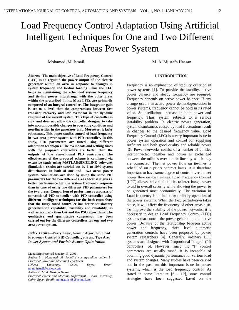
conventional PID controller to adjust the parameters
of the PID controller on-line according to the change
of the signals error and change of the error. The
proposed controller also contains a scaling gains
inputs (Ke, K∆e) as shown in Figure 7. The fuzzy
logic model using simulink in MATLAB is shown in
Figure 8 and 9, to satisfy the operational ranges (the
universe of discourse) making them more general.
Figure 7Fuzzy Self Tuning Proposed.
Figure 8 Fuzzy Logic Model Using MATLAB Simulink
Now the control action of the PID controller after self
tuning can be describing as:
dt
tdeKedtKteKU dIPPID
)()(* 222
(14)
Where KP2, KI2, and KD2 are the new gains of PID
controller and are equals to:
KP2=KP1 * KP, KI2=KI1 * KI, and KD2=KD1 *
KD (15)
Where KP1, KI1, and KD1 are the gains outputs of
fuzzy control, that are varying online with the output
of the system under control. Where KP, KI, and KD
are the initial values of the conventional PID.
Figure 9 Fuzzy Logic Model Input - Outputs
The general structure of fuzzy logic control is
represented in Fig.10 and comprises three principal
components :
Figure 10 Fuzzy Logic Control Structure
1- Fuzzification This converts input data into
suitable linguistic values. As shown in Fig
11 and 12, there are two inputs to the
controller: error and rate change of the error
signals. The error is defined as e(t) = r(t) -
y(t) , Rate of error is defined as
∆e(t)=de(t)/dt , Where r (t) is the reference
input, y (t) is the output, e (t) is the error
signal, and ∆e(t) is the rate of error. The
seventh triangular input and output member
ship functions of the fuzzy self tuning are
shown in the Figures (8,9). For the system
under study the universe of discourse for

INTERNATIONAL JOURNAL OF CONTROL, AUTOMATION AND SYSTEMS VOL. 1, NO. 1, JANUARY 2012
18
both e(t) and ∆e(t) may be normalized from
[-1,1], and the linguistic labels are {Negative
Big, , Negative , medium, Negative small,
Zero, ,Positive small, Positive medium,
Positive Big }, and are referred to in the
rules bases as {NB,NM,NS,ZE,PS,PM,PB
},and the linguistic labels of the outputs are
{Zero, Medium small, Small, Medium, Big,
Medium big, very big} and refereed to in the
rules bases as {Z,.MS, S, M, B, MB, VB}.
Figure 11 Memberships Function Of Inputs (e, ∆e).
Figure 12 Memberships Functions of Outputs
(KP1, KI1, and KD1).
2- Rule base: A decision making logic which is,
simulating a human decision process, fuzzy control
action from the knowledge of the control rules and
linguistic variable definitions. Where Ei and Ej are
the linguistic label input, UP, UI, and UD are the
linguistic label output. Tables (1), (2), and (3) show
the control rules that used for fuzzy self tuning of PID
controller.
3- Defuzzification: This yields a non fuzzy control
action from inferred fuzzy control action. The most
popular method, center of gravity or center of area is
used for defuzzification
VI. ADAPTATION OF PID CONTROLLER
USING GENETIC ALGORITHM
Genetic Algorithms (GA.s) are a stochastic global
search method [19, 20] that mimics the process of
natural evolution. It is one of the methods used for
optimization. John Holland formally introduced this
method in the United States in the 1970 at the
University of Michigan. The continuing performance

INTERNATIONAL JOURNAL OF CONTROL, AUTOMATION AND SYSTEMS VOL. 1, NO. 1, JANUARY 2012
19
improvement of computational systems has made
them attractive for some types of optimization. The
genetic algorithm starts with no knowledge of the
correct solution and depends entirely on responses
from its environment and evolution operators such as
reproduction, crossover and mutation to arrive at the
best solution. By starting at several independent
points and searching in parallel, the algorithm avoids
local minima and converging to sub optimal
solutions. In this way, GAs have been shown to be
capable of locating high performance areas in
complex domains without experiencing the
difficulties associated with high dimensionality, as
may occur with gradient decent techniques or
methods that rely on derivative information. The
steps involved in creating and implementing a genetic
algorithm:
a) Generate an initial, random population of
individuals for a fixed size.
b) Evaluate their fitness.
c) Select the fittest members of the population.
d) Reproduce using a probabilistic method
(e.g., roulette wheel).
e) Implement crossover operation on the
reproduced chromosomes
f) (choosing probabilistically both the
crossover site and the .mates.).
g) Execute mutation operation with low
probability.
h) Repeat step 2 until a predefined convergence
criterion is met.
The convergence criterion of a genetic algorithm is a
user-specified condition for example the maximum
number of generations or when the string fitness
value exceeds a certain threshold. In this paper the no
of variables is three (Kp , KI ,KD) , the population
type is double vector , population size is 20 , the
initial range of variable is [0.2– 1]. For the
reproduction , the elite count is 2 and the crossover
friction is 0.8 , the mutation function is Gaussian, the
crossover function is scattered , the stopping rules is
the no of generation is 100 , and the stall time limit is
200 sec. Genetic Algorithm Process Flow chart is
indicated in Figure 13.
I. ADAPTATION OF PID CONTROLLER
USING PSO
Optimization techniques using analogy of swarming
principle have been adopted to solve a variety of
engineering problems in the past decade. Swarm
Intelligence (SI) is an innovative distributed
intelligent paradigm for solving optimization
problems that originally took its inspiration from the
biological examples by swarming, In the earlier PSO
algorithms, each particle of the swarm is accelerated
by its best previous position and towards the best
particle in the entire swarm. Here, the underlying
assumption is that each particle in the swarm
remembers the best position already visited and also
it is informed about the best particle position. After
letting the particles to search adequate number of
times in the solution space independently for the best
possible positions, they are attracted to the basin
containing the best particle by establishing proper
communication among them about the search
environment as explained in [21- 24].
Figure 13 Genetic Algorithm Process Flow chart
Let the thi particle of the swarm is represented by
the D–dimensional vector:
1 2 ( , ,..., )i i i iDx x x x
and the best particle in the swarm, i.e. the particle
with the smallest function value, is denoted by the
index g. The best previous position (the position
giving the best function value) of the thi particle is
recorded and represented as:
1 2 ( , ,..., )i i i iDp p p p,
and the position change (velocity)
1 2 ( , ,..., )i i i iDv v v v of the
thi particle.
The particles are manipulated according to the
equations:

INTERNATIONAL JOURNAL OF CONTROL, AUTOMATION AND SYSTEMS VOL. 1, NO. 1, JANUARY 2012
20
Initialize Swarm
repeat
forall particles do
Calculate fitness f
end
for all particles do
id id 1 1 id id 2 2 gd idv = w.v + c .r .(p - x ) + c .r .(p - x )
id id idx = x + v
end
until stopping criteria
1 1 2 2 . . .( - ) . .( - )id id id id gd idv w v c r p x c r p x
(14)
id id idx x v
(15)
where d = 1, 2, . . . , D; i = 1, 2, . . . , N and N is the
size of population; w is the inertia weight;
1 2c and c are two positive constants; 1 2 r and rare
two random values in the range {0,1}. The first
equation is used to calculate thi particle’s new
velocity by taking into consideration three terms: the
particle’s previous velocity, the distance between the
particle’s best previous and current position, and,
finally, the distance between swarm’s best experience
(the position of the best particle in the swarm) and thi particle’s current position. Then, following the
second equation, the thi particle flies toward a new
position. The main steps of the PSO algorithm are
shown below:
In this paper, PSO Algorithms is used to find the
optimal parameters of the PID controller. The
structure of the PID controller with PSO algorithms is
shown in Fig. 14. A complete summary of the steps
used for PSO algorithm is indicated in Figure 15. In
this paper the no of variables is three (Kp , KI ,KD) ,
the number of birds is 50; Maximum number of
"birds steps are 50 , number of dimensions are 3 , c3
=1 , c2 =1.2 and c1 = 0.4 and the weight factor w
=0.9
I. Simulations
Simulations are done by using MATLAB simulink for
the case of one and two power system areas
connected with each other’s by tie transmission lines.
Figure 15 PID tuning using PSO algorithm
Figure 15 PSO Process Flow chart
In case of one area power system, the parameters will
be as following:
Kg1=1; Kt1=1; Tg1=0.08; Tt1=0.3; R1=2.4;
Kl1=120; Tl1=20; B1=0.425
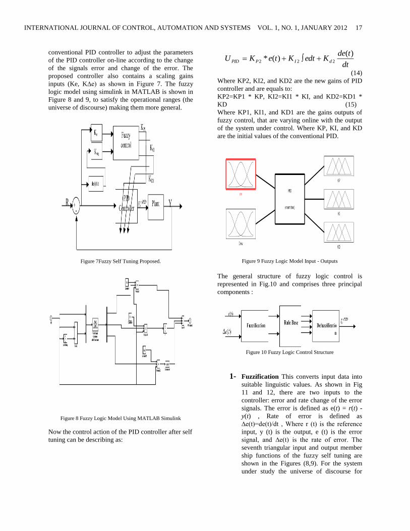
By using fuzzy logic controller, the gains of the PID
controller are changed online during the simulation
as shown in Figure 16 but by using GA and PSO, the
following optimal PID parameters are shown in Table
4.
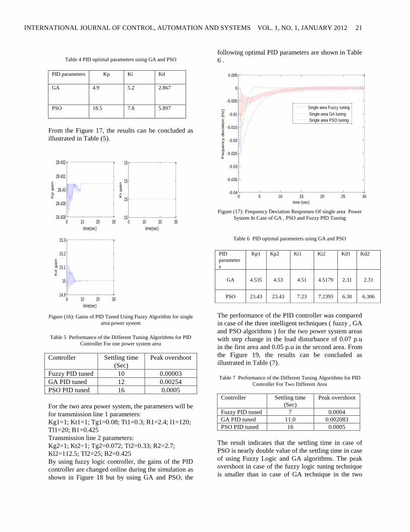
The performance of the PID controller was compared
in case of the three intelligent techniques ( fuzzy , GA
and PSO algorithms ) with step change in the load
disturbance of 0.07 p.u in the first area and 0.05 p.u
in the second area .
INTERNATIONAL JOURNAL OF CONTROL, AUTOMATION AND SYSTEMS VOL. 1, NO. 1, JANUARY 2012
21
Table 4 PID optimal parameters using GA and PSO
PID parameters Kp Ki Kd
GA 4.9 5.2 2.867
PSO 18.5 7.8 5.897
From the Figure 17, the results can be concluded as
illustrated in Table (5).
0 10 20 3028.428
28.429
28.43
28.431
28.432
time(sec)
Kp gain
0 10 20 3015
15
15
15
time(sec)
Ki gain
0 10 20 3014.9
15
15.1
15.2
15.3
time(sec)
Kd gain
Figure (16): Gains of PID Tuned Using Fuzzy Algorithm for single
area power system
Table 5 Performance of the Different Tuning Algorithms for PID
Controller For one power system area
Controller Settling time
(Sec)
Peak overshoot
Fuzzy PID tuned 10 0.00003
GA PID tuned 12 0.00254
PSO PID tuned 16 0.0005
For the two area power system, the parameters will be
for transmission line 1 parameters:
Kg1=1; Kt1=1; Tg1=0.08; Tt1=0.3; R1=2.4; l1=120;
Tl1=20; B1=0.425
Transmission line 2 parameters:
Kg2=1; Kt2=1; Tg2=0.072; Tt2=0.33; R2=2.7;
Kl2=112.5; Tl2=25; B2=0.425
By using fuzzy logic controller, the gains of the PID
controller are changed online during the simulation as
shown in Figure 18 but by using GA and PSO, the
following optimal PID parameters are shown in Table
6 .
0 5 10 15 20 25 30-0.04
-0.035
-0.03
-0.025
-0.02
-0.015
-0.01
-0.005
0
0.005
time (sec)
Fre
quency d
evia
tion (
Hz)
Single area Fuzzy tuning
Single area GA tuning
Single area PSO tuning
Figure (17): Frequency Deviation Responses Of single area Power
System In Case of GA , PSO and Fuzzy PID Tuning
Table 6 PID optimal parameters using GA and PSO
The performance of the PID controller was compared
in case of the three intelligent techniques ( fuzzy , GA
and PSO algorithms ) for the two power system areas
with step change in the load disturbance of 0.07 p.u
in the first area and 0.05 p.u in the second area. From
the Figure 19, the results can be concluded as
illustrated in Table (7).
Table 7 Performance of the Different Tuning Algorithms for PID
Controller For Two Different Area
Controller Settling time
(Sec)
Peak overshoot
Fuzzy PID tuned 7 0.0004
GA PID tuned 11.0 0.002083
PSO PID tuned 16 0.0005
The result indicates that the settling time in case of
PSO is nearly double value of the settling time in case
of using Fuzzy Logic and GA algorithms. The peak
overshoot in case of the fuzzy logic tuning technique
is smaller than in case of GA technique in the two
PID
parameter
s
Kp1 Kp2 Ki1 Ki2 Kd1 Kd2
GA 4.535 4.53 4.51 4.5179 2.31 2.31
PSO 23.43 23.43 7.23 7.2393 6.30 6.306

INTERNATIONAL JOURNAL OF CONTROL, AUTOMATION AND SYSTEMS VOL. 1, NO. 1, JANUARY 2012
22
simulations, which indicates that using fuzzy logic
controller leads to the best frequency deviation results
than the two other techniques.
0 5 10 15 2028.426
28.428
28.43
28.432
time (sec)
G
ain
of F
uzzy K
P
0 5 10 15 2015
15
15
15
time (sec)
G
ain
of F
uzzy K
I
0 5 10 15 2014.85
14.9
14.95
15
15.05
time (sec)
G
ain
of F
uzzy K
D
Figure (18): Gains of PID Tuned Using Fuzzy Algorithm for two
different area power system
0 2 4 6 8 10 12 14 16 18 20-0.035
-0.03
-0.025
-0.02
-0.015
-0.01
-0.005
0
0.005
time (sec)
fre
quency d
evia
tion (
Hz)
area 1 response using fuzzy logic
area 2 response using fuzzy logic
area 1 response using GA
area 2 response using GA
area 1 response using PSO
area 2 response using PSO
Figure (19): Frequency Deviation Responses Of Two Power
System Areas In Case of GA , PSO and Fuzzy PID Tuning
II. Conclusion
In this proposed study, a new GA, PSO and fuzzy
Algorithm based PID has been introduced for
automatic load frequency control of a multi area
power system. For this purpose, first, more adaptive
tuning mechanism for the PID controller parameters
is obtained. It has been shown that the proposed
control algorithms are effective and provides
significant improvement in system performance.
Therefore, the proposed PID controllers are
recommended to generate good quality and reliable
electric energy. In addition, the proposed controllers
are very simple and easy to implement since it does
not require many information about system
parameters. Simulations are done by using the same
PID parameters for the two different areas because it
gives a better performance for the system frequency
response than in case of using two different PID
parameters for the two areas. This research is the
starting of applying the AI algorithms on the four
different area power system which will be future
work. Comparison study of the proposed PID
controllers with each other’s was presented.
References
[1] A. Salami, S. Jadid, and N. Ramezani, “The Effect of load
frequency controller on load pickup during restoration,” 1st
International Power and Energy Conference, PECON
2006, pp. 225-228, 2006.
[2] H.S. Moghanlou and H.A. Shayanfar, “Robust decentralized
LFC design in a restructured power system,” International
Journal of Emerging Electric Power Systems, vol. 6. no. 2,
Art. 4, 2006.
[3] Y.Wang, R.Zhou and C.Wen “Robust Load Frequency
Controller Design For Power Systems” IEE Proceedings C.
Generation, Transmission and Distribution. Vol. 140, No. 1.
- 1993. - pp. 11-16.
[4] H. Shayeghi, H.A. Shayanfar b, A. Jalili “Load Frequency
Control Strategies A State Of The Art Survey for The
Researcher “Energy Conversion and Management Journal. -
2009. - pp. 344-353.
[5] C.S. Chang and W. Fu “Area load frequency control using
fuzzy gain scheduling of PI controllers,” Electrical Power
and Energy Systems, vol. 42, no. 2, pp. 145-152, 1997.
[6] Bevrani Hassan “Robust Power System Frequency Control”
[Book]. - Brisbane, Australia : Springer Science + Business
Media, LLC, 2009.
[7] P. Kundur “Power System Stability And Control “ [Book]. -
New York : McGraw-Hill, 1994.
[8] Kazemi, Ahad and Amini, Arman “Lead/Lag SSSC Based
Controller for Stabilization of Frequency Oscillations in
Multi-Area Power System” 20th International Power System
Conference. - Tehran- Iran : 98-E-PSS-148, 2005. - pp. 1-9.
[9] V.D.M. Kumar, “Intelligent controllers for automatic
generation control,” IEEE Region 10 International
Conference on Global Connectivity in Energy, Computer,
Communication and Control, TENCON ‘98, vol. 2, pp.
557-574, 1998.
[10] A. Ismail, “Improving UAE power systems control
performance by using combined LFC and AVR,” The

INTERNATIONAL JOURNAL OF CONTROL, AUTOMATION AND SYSTEMS VOL. 1, NO. 1, JANUARY 2012
23
Seventh U.A.E. University Research Conference, ENG., pp.
50-60, 2006.
[11] M. A. Tammam , “ Multi Objective Genetic Algorithm
Controller’s Tuning for load Frequency Control In Electric
Power systems “, M. Sc., Cairo University, 2011
[12] S.P. Ghoshal “Multi-area Frequency and Tie-line Power
Flow Control with Fuzzy Logic Based Integral Gain
Scheduling” Journal-EL, Vol 84. - 2003.
[13] Mathur H.D. and Manjunath H.V. “Frequency Stabilization
using Fuzzy Logic Based Controller for Multi-area Power
System” The South Pacific Journal of Natural Science. -
2007. - pp. 22-30.
[14] R.Shankar Naik, K.ChandraSekhar, K.Vaisakh
“Adaptive PSO Based Optimal Fuzzy Controller Design for
AGC Equipped with SMES and SPSS”, Journal of
Theoretical and Applied Information Technology. pp. 8 -
16.
[15] M. A. Tammam, M. A. Moustafa, M. A. E. S. Abo Ela and
A. E. A. Seif “ Load Frequency Control Using Genetic
Algorithm Based PID Controller For Single Area Power
System “International 12 5 Conference on Renewable
Energies and Power Quality (ICREPQ’11). - Las Palmas de
Gran Canaria (Spain), 2010.
[16] Abd-Elazim S.M and Salim E. Ali “ Optimal PID Tuning for
Load Frequency Control Using Bacteria Foraging
Optimization Algorithm “14th International Middle East
Power Systems Conference (MEPCON’10). - Cairo –
Egypt, Cairo University, 2010. - pp. 410 - 415.
[17] Haluk GÖZDE1 M. Cengiz TAPLAMACIOĞLU2, İlhan
KOCAARSLAN3 and Ertugrul ÇAM “Particle Swarm
Optimization Based Load Frequency Control in A Single
Area Power System” University Of Pitesti – Electronics
And Computers Science, Scientific Bulletin, No. 8, Vol. 2. -
2008. - pp. 1453–1119.
[18] B. Venkata Prasanth, Dr. S. V. Jayaram Kumar , “Robust
Fuzzy Load Frequency Controller for a Two Area
Interconnected Power System ”, Journal of Theoretical and
Applied Information Technology. pp. 242 - 252.
[19] Ndubisi Samuel N , “An intelligent fuzzy logic controller
applied to multi-area load frequency
Control , American Journal of Scientific and Industrial
Research , pp 220-226
[20] Y.H. Song and A.T. Johns, “Applications of fuzzy logic in
power systems: part 1 general introduction to fuzzy logic,”
Power Engineering Journal, pp. 219-222, 1997.
[21] Y.H. Song and A.T. Johns, “Applications of fuzzy logic in
power systems: part 2 comparison and integration with
expert systems, neural networks and genetic algorithms,”
Power Engineering Journal, pp.185-190, 1998.
[22] Y.H. Song and A.T. Johns, “Applications of fuzzy logic in
power systems: part 3 example applications,” Power
Engineering Journal, pp.97-103, 1999.
[23] Johan Anderson “Applications of a Multi-objective Genetic
Algorithm to Engineering Design Problems”, Springer
Berlin, ISBN 0302-9743
[24] Colin R. Reeves, Jonathan E. Rowe, ”Genetic algorithm
Principles and perspective, A Guide to GA theory”, Kluwer
Academic Publishers, ISBN 1-4020-7240-6, 2002
[25] M.O. Tokhi and M.S. Alam " Particle Swarm Optimization
Algorithms and Their Application to Controller Design for
Flexible Structure system".
[26] Nadia Nedjah,” Swarm Intelligent Systems”, Studies in
Computational Intelligence, Springer, vol 26
[27] K.E. Parsopoulos and M.N. Vrahatis. Recent approaches to
global optimization problems through particle swarm
optimization. Natural Computing 1: 235 – 306, 2002.
[28] JI Zhen ,WANGYiwei ,CHUYing and WUQinghua
“Bacterial Particle Swarm Optimization “Chinese Journal of
Electronics Vol.18, No.2, Apr. 2009