INTERNATIONAL IEC STANDARD 60502-2 - cold shrink 60502-2 2005.pdf · 2014-11-19 · IEC...
86
Power cables with extruded insulation and their accessories for rated voltages from 1 kV ( U m = 1,2 kV) up to 30 kV ( U m = 36 kV) – Part 2: Cables for rated voltages from 6 kV ( U m = 7,2 kV) up to 30 kV ( U m = 36 kV) Reference number IEC 60502-2:2005(E) INTERNATIONAL STANDARD IEC 60502-2 Second edition 2005-03 This English-language version is derived from the original bilingual publication by leaving out all French-language pages. Missing page numbers correspond to the French- language pages.
Transcript of INTERNATIONAL IEC STANDARD 60502-2 - cold shrink 60502-2 2005.pdf · 2014-11-19 · IEC...
Power cables with extruded insulation and their accessories for rated voltages from 1 kV (Um = 1,2 kV) up to 30 kV (Um = 36 kV) –
Part 2: Cables for rated voltages from 6 kV (Um = 7,2 kV) up to 30 kV (Um = 36 kV)
Reference number IEC 60502-2:2005(E)
INTERNATIONAL STANDARD
IEC60502-2
Second edition2005-03
This English-language version is derived from the original bilingual publication by leaving out all French-language pages. Missing page numbers correspond to the French-language pages.

Publication numbering
As from 1 January 1997 all IEC publications are issued with a designation in the 60000 series. For example, IEC 34-1 is now referred to as IEC 60034-1.
Consolidated editions
The IEC is now publishing consolidated versions of its publications. For example, edition numbers 1.0, 1.1 and 1.2 refer, respectively, to the base publication, the base publication incorporating amendment 1 and the base publication incorporating amendments 1 and 2.
Further information on IEC publications
The technical content of IEC publications is kept under constant review by the IEC, thus ensuring that the content reflects current technology. Information relating to this publication, including its validity, is available in the IEC Catalogue of publications (see below) in addition to new editions, amendments and corrigenda. Information on the subjects under consideration and work in progress undertaken by the technical committee which has prepared this publication, as well as the list of publications issued, is also available from the following:
• IEC Web Site (www.iec.ch)
• Catalogue of IEC publications
The on-line catalogue on the IEC web site (www.iec.ch/searchpub) enables you to search by a variety of criteria including text searches, technical committees and date of publication. On-line information is also available on recently issued publications, withdrawn and replaced publications, as well as corrigenda.
• IEC Just Published
This summary of recently issued publications (www.iec.ch/online_news/ justpub) is also available by email. Please contact the Customer Service Centre (see below) for further information.
• Customer Service Centre
If you have any questions regarding this publication or need further assistance, please contact the Customer Service Centre:
Email: [email protected] Tel: +41 22 919 02 11 Fax: +41 22 919 03 00
Power cables with extruded insulation and their accessories for rated voltages from 1 kV (Um = 1,2 kV) up to 30 kV (Um = 36 kV) –
Part 2: Cables for rated voltages from 6 kV (Um = 7,2 kV) up to 30 kV (Um = 36 kV)
For price, see current catalogue
IEC 2005 Copyright - all rights reserved
No part of this publication may be reproduced or utilized in any form or by any means, electronic or mechanical, including photocopying and microfilm, without permission in writing from the publisher.
International Electrotechnical Commission, 3, rue de Varembé, PO Box 131, CH-1211 Geneva 20, SwitzerlandTelephone: +41 22 919 02 11 Telefax: +41 22 919 03 00 E-mail: [email protected] Web: www.iec.ch
INTERNATIONAL STANDARD
IEC60502-2
Second edition2005-03
XC Commission Electrotechnique InternationaleInternational Electrotechnical CommissionМеждународная Электротехническая Комиссия
PRICE CODE
60502-2 IEC:2005 – 3 –
CONTENTS
FOREWORD ......................................................................................................................13
1 Scope ..........................................................................................................................17 2 Normative references ...................................................................................................17 3 Terms and definitions ...................................................................................................19
3.1 Definitions of dimensional values (thicknesses, cross-sections, etc.) ....................19 3.2 Definitions concerning the tests ...........................................................................21
4 Voltage designations and materials ..............................................................................21 4.1 Rated voltages ....................................................................................................21 4.2 Insulating compounds..........................................................................................23 4.3 Sheathing compounds .........................................................................................25
5 Conductors...................................................................................................................27 6 Insulation .....................................................................................................................27
6.1 Material ...............................................................................................................27 6.2 Insulation thickness .............................................................................................27
7 Screening.....................................................................................................................29 7.1 Conductor screen ................................................................................................31 7.2 Insulation screen .................................................................................................31
8 Assembly of three-core cables, inner coverings and fillers ............................................31 8.1 Inner coverings and fillers....................................................................................31 8.2 Cables having a collective metallic layer (see Clause 9).......................................33 8.3 Cables having a metallic layer over each individual core (see Clause 10) ............33
9 Metallic layers for single-core and three-core cables .....................................................35 10 Metallic screen .............................................................................................................35
10.1 Construction ........................................................................................................35 10.2 Requirements ......................................................................................................35 10.3 Metallic screens not associated with semi-conducting layers ................................35
11 Concentric conductor....................................................................................................35 11.1 Construction ........................................................................................................35 11.2 Requirements ......................................................................................................37 11.3 Application ..........................................................................................................37
12 Metallic sheath .............................................................................................................37 12.1 Lead sheath ........................................................................................................37 12.2 Other metallic sheaths .........................................................................................37
13 Metallic armour ............................................................................................................37 13.1 Types of metallic armour .....................................................................................37 13.2 Materials .............................................................................................................39 13.3 Application of armour...........................................................................................39 13.4 Dimensions of the armour wires and armour tapes ...............................................41 13.5 Correlation between cable diameters and armour dimensions ..............................41 13.6 Round or flat wire armour ....................................................................................43 13.7 Double tape armour .............................................................................................43

60502-2 IEC:2005 – 5 –
14 Oversheath ..................................................................................................................43 14.1 General ...............................................................................................................43 14.2 Material ...............................................................................................................45 14.3 Thickness............................................................................................................45
15 Test conditions .............................................................................................................45 15.1 Ambient temperature ...........................................................................................45 15.2 Frequency and waveform of power frequency test voltages ..................................45 15.3 Waveform of impulse test voltages.......................................................................45
16 Routine tests ................................................................................................................47 16.1 General ...............................................................................................................47 16.2 Electrical resistance of conductors.......................................................................47 16.3 Partial discharge test ...........................................................................................47 16.4 Voltage test .........................................................................................................47
17 Sample tests ................................................................................................................49 17.1 General ...............................................................................................................49 17.2 Frequency of sample tests ...................................................................................51 17.3 Repetition of tests ...............................................................................................51 17.4 Conductor examination ........................................................................................51 17.5 Measurement of thickness of insulation and of non-metallic sheaths
(including extruded separation sheaths, but excluding inner extruded coverings) ...........................................................................................................51
17.6 Measurement of thickness of lead sheath ............................................................53 17.7 Measurement of armour wires and tapes..............................................................55 17.8 Measurement of external diameter .......................................................................55 17.9 Voltage test for 4 h ..............................................................................................55 17.10 Hot set test for EPR, HEPR and XLPE insulations and elastomeric sheaths..........57
18 Type tests, electrical ....................................................................................................57 18.1 Cables having conductor screens and insulation screens .....................................57 18.2 Cables of rated voltage 3,6/6 (7,2) kV having unscreened insulation ....................65
19 Type tests, non-electrical..............................................................................................69 19.1 Measurement of thickness of insulation................................................................69 19.2 Measurement of thickness of non-metallic sheaths (including extruded
separation sheaths, but excluding inner coverings) ..............................................69 19.3 Tests for determining the mechanical properties of insulation before and
after ageing .........................................................................................................69 19.4 Tests for determining the mechanical properties of non-metallic sheaths
before and after ageing .......................................................................................71 19.5 Additional ageing test on pieces of completed cables ...........................................71 19.6 Loss of mass test on PVC sheaths of type ST2 ....................................................73 19.7 Pressure test at high temperature on insulations and non-metallic sheaths...........73 19.8 Test on PVC insulation and sheaths at low temperatures .....................................73 19.9 Test for resistance of PVC insulation and sheaths to cracking (heat shock
test) ....................................................................................................................73 19.10 Ozone resistance test for EPR and HEPR insulations...........................................75 19.11 Hot set test for EPR, HEPR and XLPE insulations and elastomeric sheaths..........75 19.12 Oil immersion test for elastomeric sheaths ...........................................................75 19.13 Water absorption test on insulation ......................................................................75

60502-2 IEC:2005 – 7 –
19.14 Flame spread test on single cables ......................................................................75 19.15 Measurement of carbon black content of black PE oversheaths............................75 19.16 Shrinkage test for XLPE insulation .......................................................................77 19.17 Thermal stability test for PVC insulation...............................................................77 19.18 Determination of hardness of HEPR insulation .....................................................77 19.19 Determination of the elastic modulus of HEPR insulation......................................77 19.20 Shrinkage test for PE oversheaths .......................................................................77 19.21 Strippability test for insulation screen ..................................................................79 19.22 Water penetration test .........................................................................................79
20 Electrical tests after installation ....................................................................................81 20.1 D.C. voltage test of the oversheath ......................................................................81 20.2 Insulation test......................................................................................................81
Annex A (normative) Fictitious calculation method for determination of dimensions of protective coverings............................................................................................................93 Annex B (informative) Tabulated continuous current ratings for cables having extruded insulation and a rated voltage from 3,6/6 kV up to 18/30 kV ................................103 Annex C (normative) Rounding of numbers ......................................................................143 Annex D (normative) Method of measuring resistivity of semi-conducting screens ............145 Annex E (normative) Determination of hardness of HEPR insulations ...............................149 Annex F (normative) Water penetration test .....................................................................153 Bibliography .....................................................................................................................157 Figure B.1 – Single-core cables in air................................................................................105 Figure B.2 – Single-core cables buried direct ....................................................................107 Figure B.3 – Single-core cables in earthenware ducts .......................................................107 Figure B.4 – Three-core cables .........................................................................................109 Figure D.1a – Measurement of the volume resistivity of the conductor screen....................147 Figure D.1b – Measurement of the volume resistivity of the insulation screen ....................147 Figure D.1 – Preparation of samples for measurement of resistivity of conductor and insulation screens.............................................................................................................147 Figure E.1 – Test on surfaces of large radius of curvature .................................................151 Figure E.2 – Test on surfaces of small radius of curvature.................................................151 Figure F.1 – Schematic diagram of apparatus for water penetration test ............................155
Table 1 – Recommended rated voltages U0 ........................................................................23 Table 2 – Insulating compounds..........................................................................................25 Table 3 – Maximum conductor temperatures for different types of insulating compound .......25 Table 4 – Maximum conductor temperatures for different types of sheathing compound ..........................................................................................................................27 Table 5 – Nominal thickness of PVC/B insulation ................................................................27 Table 6 – Nominal thickness of cross-linked polyethylene (XLPE) insulation ........................29

60502-2 IEC:2005 – 9 –
Table 7 – Nominal thickness of ethylene propylene rubber (EPR) and hard ethylene propylene rubber (HEPR) insulation ....................................................................................29 Table 8 – Thickness of extruded inner covering...................................................................33 Table 9 – Nominal diameter of round armour wires..............................................................41 Table 10 – Nominal thickness of armour tapes ....................................................................43 Table 11 – Routine test voltages .........................................................................................49 Table 12 – Number of samples for sample tests ..................................................................51 Table 13 – Sample test voltages .........................................................................................57 Table 14 – Impulse voltages ...............................................................................................63 Table 15 – Electrical type test requirements for insulating compounds.................................81 Table 16 – Non-electrical type tests (see Tables 17 to 23) ..................................................83 Table 17 – Test requirements for mechanical characteristics of insulating compounds (before and after ageing) ....................................................................................................85 Table 18 – Test requirements for particular characteristics for PVC insulating compound ..........................................................................................................................85 Table 19 – Test requirements for particular characteristics of various thermosetting insulating compounds .........................................................................................................87 Table 20 – Test requirements for mechanical characteristics of sheathing compounds (before and after ageing) ....................................................................................................87 Table 21 – Test requirements for particular characteristics for PVC sheathing compounds.........................................................................................................................89 Table 22 – Test requirements for particular characteristics of PE (thermoplastic polyethylene) sheathing compounds ...................................................................................89 Table 23 – Test requirements for particular characteristics of elastomeric sheathing compound ..........................................................................................................................91 Table A.1 – Fictitious diameter of conductor........................................................................95 Table A.2 – Increase of diameter for concentric conductors and metallic screens ................97 Table A.3 – Increase of diameter for additional bedding ....................................................101 Table B.1 – Nominal screen cross-sectional areas ............................................................103 Table B.2 – Current ratings for single-core cables with XLPE insulation Rated voltage 3,6/6 kV to 18/30 kV * Copper conductor...........................................................................111 Table B.3 – Current ratings for single-core cables with XLPE insulation Rated voltage 3,6/6 kV to 18/30 kV * Aluminium conductor ......................................................................113 Table B.4 – Current ratings for single-core cables with EPR insulation Rated voltage 3,6/6 kV to 18/30 kV * Copper conductor...........................................................................115 Table B.5 – Current ratings for single-core cables with EPR insulation Rated voltage 3,6/6 kV to 18/30 kV * Aluminium conductor ......................................................................117 Table B.6 – Current rating for three-core XLPE insulated cables Rated voltage 3,6/6 kV to 18/30 kV * Copper conductor Armoured and unarmoured ........................................119 Table B.7 – Current rating for three-core XLPE insulated cables Rated voltage 3,6/6 kV to 18/30 kV * Aluminium conductor Armoured and unarmoured....................................121 Table B.8 – Current rating for three-core EPR insulated cables Rated voltage 3,6/6 kV to 18/30 kV * Copper conductor Armoured and unarmoured ..............................................123
60502-2 IEC:2005 – 11 –
Table B.9 – Current rating for three-core EPR insulated cables Rated voltage 3,6/6 kV to 18/30 kV * Aluminium conductor Armoured and unarmoured..........................................125 Table B.10 – Correction factors for ambient air temperatures other than 30 °C ..................127 Table B.11 – Correction factors for ambient ground temperatures other than 20 °C ...........127 Table B.12 – Correction factors for depths of laying other than 0,8 m for direct buried cables ..............................................................................................................................127 Table B.13 – Correction factors for depths of laying other than 0,8 m for cables in ducts ................................................................................................................................129 Table B.14 – Correction factors for soil thermal resistivities other than 1,5 K•m/W for direct buried single-core cables ........................................................................................129 Table B.15 – Correction factors for soil thermal resistivities other than 1,5 K•m/W single-core cables in buried ducts .....................................................................................131 Table B.16 – Correction factors for soil thermal resistivities other than 1,5 K•m/W for direct buried three-core cables .........................................................................................131 Table B.17 – Correction factors for soil thermal resistivities other than 1,5 K•m/W for three-core cables in ducts.................................................................................................133 Table B.18 – Correction factors for groups of 3-core cables in horizontal formation laid direct in the ground ....................................................................................................133 Table B.19 – Correction factors for groups of 3-phase circuits of single-core cables laid direct in the ground ....................................................................................................135 Table B.20 – Correction factors for groups of 3-core cables in single way ducts in horizontal formation ..........................................................................................................135 Table B.21 – Correction factors for groups of 3-phase circuits of single-core cables in single-way ducts ...............................................................................................................137 Table B.22 – Reduction factors for groups of more than one multi-core cable in air To be applied to the current-carrying capacity for one multi-core cable in free air ...................139 Table B.23 – Reduction factors for groups of more than one circuit of single-core cables (Note 2) To be applied to the current-carrying capacity for one circuit of single-core cables in free air .......................................................................................................141
60502-2 IEC:2005 – 13 –
INTERNATIONAL ELECTROTECHNICAL COMMISSION ___________
POWER CABLES WITH EXTRUDED INSULATION AND THEIR ACCESSORIES FOR RATED VOLTAGES FROM 1 kV (Um = 1,2 kV) UP TO 30 kV (Um = 36 kV) –
Part 2: Cables for rated voltages from 6 kV
(Um = 7,2 kV) up to 30 kV (Um = 36 kV)
FOREWORD
1) The International Electrotechnical Commission (IEC) is a worldwide organization for standardization comprising all national electrotechnical committees (IEC National Committees). The object of IEC is to promote international co-operation on all questions concerning standardization in the electrical and electronic fields. To this end and in addition to other activities, IEC publishes International Standards, Technical Specifications, Technical Reports, Publicly Available Specifications (PAS) and Guides (hereafter referred to as “IEC Publication(s)”). Their preparation is entrusted to technical committees; any IEC National Committee interested in the subject dealt with may participate in this preparatory work. International, governmental and non-governmental organizations liaising with the IEC also participate in this preparation. IEC collaborates closely with the International Organization for Standardization (ISO) in accordance with conditions determined by agreement between the two organizations.
2) The formal decisions or agreements of IEC on technical matters express, as nearly as possible, an international consensus of opinion on the relevant subjects since each technical committee has representation from all interested IEC National Committees.
3) IEC Publications have the form of recommendations for international use and are accepted by IEC National Committees in that sense. While all reasonable efforts are made to ensure that the technical content of IEC Publications is accurate, IEC cannot be held responsible for the way in which they are used or for any misinterpretation by any end user.
4) In order to promote international uniformity, IEC National Committees undertake to apply IEC Publications transparently to the maximum extent possible in their national and regional publications. Any divergence between any IEC Publication and the corresponding national or regional publication shall be clearly indicated in the latter.
5) IEC provides no marking procedure to indicate its approval and cannot be rendered responsible for any equipment declared to be in conformity with an IEC Publication.
6) All users should ensure that they have the latest edition of this publication.
7) No liability shall attach to IEC or its directors, employees, servants or agents including individual experts and members of its technical committees and IEC National Committees for any personal injury, property damage or other damage of any nature whatsoever, whether direct or indirect, or for costs (including legal fees) and expenses arising out of the publication, use of, or reliance upon, this IEC Publication or any other IEC Publications.
8) Attention is drawn to the Normative references cited in this publication. Use of the referenced publications is indispensable for the correct application of this publication.
9) Attention is drawn to the possibility that some of the elements of this IEC Publication may be the subject of patent rights. IEC shall not be held responsible for identifying any or all such patent rights.
International Standard IEC 60502-2 has been prepared by IEC technical committee 20: Electric cables.
This second edition cancels and replaces the first edition published in 1997, its amendment 1 (1998) and its corrigendum 1 (1999) and constitutes a technical revision.
Significant technical changes with respect to the first edition have been made. The changes relate to possible water ingress, large conductor sizes, partial discharge requirements, insulation and oversheath thickness requirements, range of type approval, electrical tests after installation and tabulated current ratings.

60502-2 IEC:2005 – 15 –
IEC 60502 consists of the following parts, under the general title Power cables with extruded insulation and their accessories for rated voltages from 1 kV (Um = 1,2 kV) up to 30 kV (Um = 36 kV):
Part 1: Cables for rated voltages of 1 kV (Um = 1,2 kV) and 3 kV (Um = 3,6 kV); Part 2: Cables for rated voltages from 6 kV (Um = 7,2 kV) up to 30 kV (Um = 36 kV); Part 3: Reserved; Part 4: Test requirements on accessories for cables with rated voltages from 6 kV
(Um = 7,2 kV) up to 30 kV (Um = 36 kV).
The text of this standard is based on the following documents:
FDIS Report on voting
20/749/FDIS 20/763/RVD
Full information on the voting for the approval of this standard can be found in the report on voting indicated in the above table.
This publication has been drafted in accordance with the ISO/IEC Directives, Part 2.
The committee has decided that the contents of this publication will remain unchanged until the maintenance result date indicated on the IEC web site under "http://webstore.iec.ch" in the data related to the specific publication. At this date, the publication will be
• reconfirmed; • withdrawn; • replaced by a revised edition, or • amended.

60502-2 IEC:2005 – 17 –
POWER CABLES WITH EXTRUDED INSULATION AND THEIR ACCESSORIES FOR RATED VOLTAGES
FROM 1 kV (Um = 1,2 kV) UP TO 30 kV (Um = 36 kV) –
Part 2: Cables for rated voltages from 6 kV (Um = 7,2 kV) up to 30 kV (Um = 36 kV)
1 Scope
This part of IEC 60502 specifies the construction, dimensions and test requirements of power cables with extruded solid insulation from 6 kV up to 30 kV for fixed installations such as distribution networks or industrial installations.
When determining applications, it is recommended that the possible risk of radial water ingress is considered. Cable designs with barriers claimed to prevent longitudinal water penetration and an associated test are included in this part of IEC 60502.
Cables for special installation and service conditions are not included, for example cables for overhead networks, the mining industry, nuclear power plants (in and around the containment area) nor for submarine use or shipboard application.
2 Normative references
The following referenced documents are indispensable for the application of this document. For dated references, only the edition cited applies. For undated references, the latest edition of the referenced document (including any amendments) applies.
IEC 60038, IEC standard voltages
IEC 60060-1, High-voltage test techniques – Part 1: General definitions and test requirements
IEC 60183, Guide to the selection of high-voltage cables
IEC 60228, Conductors of insulated cables
IEC 60229, Tests on cable oversheaths which have a special protective function and are applied by extrusion
IEC 60230, Impulse tests on cables and their accessories
IEC 60332-1-2, Tests on electric and optical fibre cables under fire conditions – Part 1-2: Test for vertical flame propagation for a single insulated wire or cable – Procedure for 1 kW pre-mixed flame
IEC 60811-1-1, Common test methods for insulating and sheathing materials of electric cables and optical cables – Part 1-1: Methods for general application – Measurement of thickness and overall dimensions – Tests for determining the mechanical properties

60502-2 IEC:2005 – 19 –
IEC 60811-1-2, Common test methods for insulating and sheathing materials of electric cables – Part 1: Methods for general application – Section 2: Thermal ageing methods
IEC 60811-1-3, Common test methods for insulating and sheathing materials of electric and optical cables – Part 1-3: General application – Methods for determining the density – Water absorption tests – Shrinkage test
IEC 60811-1-4, Common test methods for insulating and sheathing materials of electric cables – Part 1: Methods for general application – Section 4: Test at low temperature
IEC 60811-2-1, Common test methods for insulating and sheathing materials of electric and optical cables – Part 2-1: Methods specific to elastomeric compounds – Ozone resistance, hot set and mineral oil immersion tests
IEC 60811-3-1, Common test methods for insulating and sheathing materials of electric cables – Part 3: Methods specific to PVC compounds – Section 1: Pressure test at high temperature – Tests for resistance to cracking
IEC 60811-3-2, Common test methods for insulating and sheathing materials of electric cables – Part 3: Methods specific to PVC compounds – Section 2: Loss of mass test – Thermal stability test
IEC 60811-4-1, Insulating and sheathing materials of electric and optical cables – Common test methods – Part 4-1: Methods specific to polyethylene and polypropylene compounds – Resistance to environmental stress cracking – Measurement of the melt flow index – Carbon black and/or mineral filler content measurement in polyethylene by direct combustion – Measurement of carbon black content by thermogravimetric analysis (TGA) – Assessment of carbon black dispersion in polyethylene using a microscope
IEC 60885-3, Electrical test methods for electric cables – Part 3: Test methods for partial discharge measurements on lengths of extruded power cables
IEC 60986, Short-circuit temperature limits of electric cables with rated voltages from 6 kV (Um 7,2 kV) up to 30 kV (Um =36 kV)
ISO 48, Rubber, vulcanized or thermoplastic – Determination of hardness (hardness between 10 IRHD and 100 IRHD)
3 Terms and definitions
For the purpose of this document, the following terms and definitions apply.
3.1 Definitions of dimensional values (thicknesses, cross-sections, etc.)
3.1.1 nominal value value by which a quantity is designated and which is often used in tables
NOTE Usually, in this standard, nominal values give rise to values to be checked by measurements taking into account specified tolerances.
3.1.2 approximate value value which is neither guaranteed nor checked; it is used, for example, for the calculation of other dimensional values

60502-2 IEC:2005 – 21 –
3.1.3 median value when several test results have been obtained and ordered in an increasing (or decreasing) succession, the median value is the middle value if the number of available values is odd, and the mean of the two middle values if the number is even
3.1.4 fictitious value value calculated according to the "fictitious method'' described in Annex A
3.2 Definitions concerning the tests
3.2.1 routine tests tests made by the manufacturer on each manufactured length of cable to check that each length meets the specified requirements
3.2.2 sample tests tests made by the manufacturer on samples of completed cable or components taken from a completed cable, at a specified frequency, so as to verify that the finished product meets the specified requirements
3.2.3 type tests tests made before supplying, on a general commercial basis, a type of cable covered by this standard, in order to demonstrate satisfactory performance characteristics to meet the intended application
NOTE These tests are of such a nature that, after they have been made, they need not be repeated, unless changes are made in the cable materials or design or manufacturing process which might change the performance characteristics.
3.2.4 electrical tests after installation tests made to demonstrate the integrity of the cable and its accessories as installed
4 Voltage designations and materials
4.1 Rated voltages
The rated voltages U0/U(Um) of the cables considered in this standard are as follows:
U0/U(Um) = 3,6/6 (7,2) – 6/10 (12) – 8,7/15 (17,5) – 12/20 (24) – 18/30 (36) kV.
NOTE 1 The voltages given above are the correct designations although in some countries other designations are used, e.g. 3,5/6 – 5,8/10 – 11,5/20 – 17,3/30 kV.
In the voltage designation of cables U0/U(Um):
U0 is the rated power frequency voltage between conductor and earth or metallic screen for which the cable is designed;
U is the rated power frequency voltage between conductors for which the cable is designed;
Um is the maximum value of the "highest system voltage'' for which the equipment may be used (see IEC 60038).
60502-2 IEC:2005 – 23 –
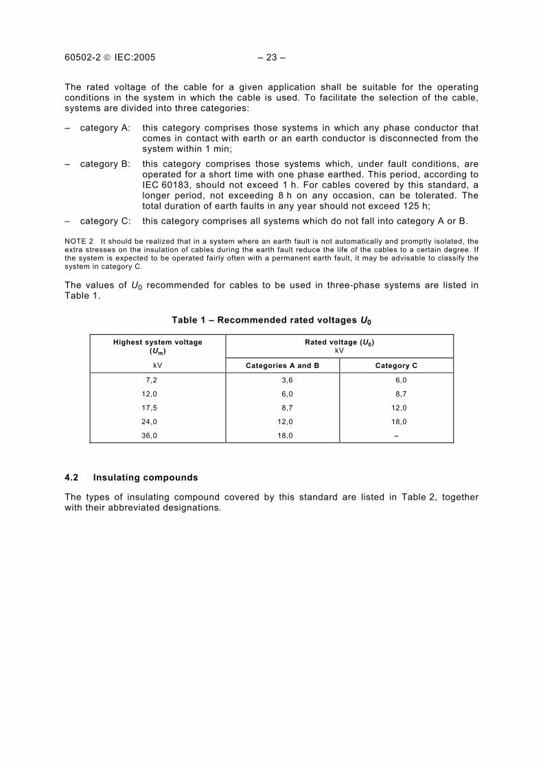
The rated voltage of the cable for a given application shall be suitable for the operating conditions in the system in which the cable is used. To facilitate the selection of the cable, systems are divided into three categories:
– category A: this category comprises those systems in which any phase conductor that comes in contact with earth or an earth conductor is disconnected from the system within 1 min;
– category B: this category comprises those systems which, under fault conditions, are operated for a short time with one phase earthed. This period, according to IEC 60183, should not exceed 1 h. For cables covered by this standard, a longer period, not exceeding 8 h on any occasion, can be tolerated. The total duration of earth faults in any year should not exceed 125 h;
– category C: this category comprises all systems which do not fall into category A or B.
NOTE 2 It should be realized that in a system where an earth fault is not automatically and promptly isolated, the extra stresses on the insulation of cables during the earth fault reduce the life of the cables to a certain degree. If the system is expected to be operated fairly often with a permanent earth fault, it may be advisable to classify the system in category C.
The values of U0 recommended for cables to be used in three-phase systems are listed in Table 1.
Table 1 – Recommended rated voltages U0
Highest system voltage (Um)
Rated voltage (U0) kV
kV Categories A and B Category C
7,2
12,0
17,5
24,0
36,0
3,6
6,0
8,7
12,0
18,0
6,0
8,7
12,0
18,0
–
4.2 Insulating compounds
The types of insulating compound covered by this standard are listed in Table 2, together with their abbreviated designations.
60502-2 IEC:2005 – 25 –
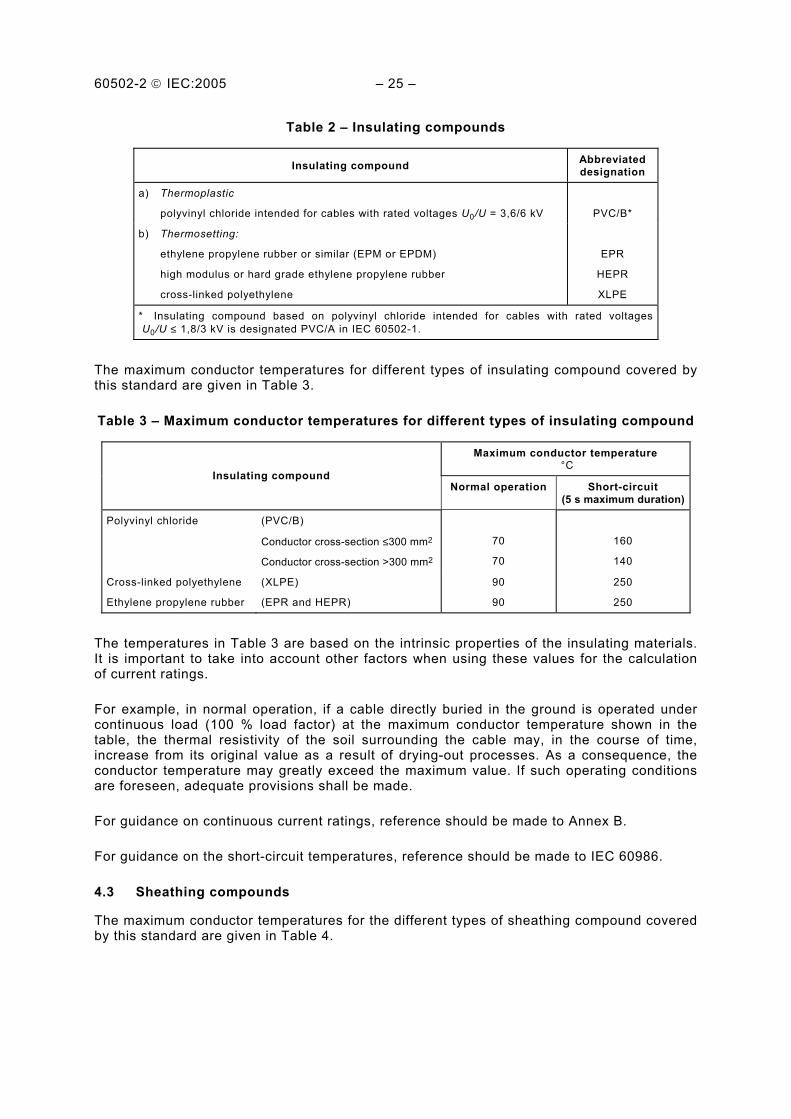
Table 2 – Insulating compounds
Insulating compound Abbreviated designation
a) Thermoplastic
polyvinyl chloride intended for cables with rated voltages U0/U = 3,6/6 kV
PVC/B*
b) Thermosetting:
ethylene propylene rubber or similar (EPM or EPDM)
high modulus or hard grade ethylene propylene rubber
cross-linked polyethylene
EPR
HEPR
XLPE
* Insulating compound based on polyvinyl chloride intended for cables with rated voltages U0/U ≤ 1,8/3 kV is designated PVC/A in IEC 60502-1.
The maximum conductor temperatures for different types of insulating compound covered by this standard are given in Table 3.
Table 3 – Maximum conductor temperatures for different types of insulating compound
Maximum conductor temperature °C
Insulating compound Normal operation Short-circuit
(5 s maximum duration)
Polyvinyl chloride
(PVC/B)
Conductor cross-section ≤300 mm2
Conductor cross-section >300 mm2
70
70
160
140
Cross-linked polyethylene
Ethylene propylene rubber
(XLPE)
(EPR and HEPR)
90
90
250
250
The temperatures in Table 3 are based on the intrinsic properties of the insulating materials. It is important to take into account other factors when using these values for the calculation of current ratings.
For example, in normal operation, if a cable directly buried in the ground is operated under continuous load (100 % load factor) at the maximum conductor temperature shown in the table, the thermal resistivity of the soil surrounding the cable may, in the course of time, increase from its original value as a result of drying-out processes. As a consequence, the conductor temperature may greatly exceed the maximum value. If such operating conditions are foreseen, adequate provisions shall be made.
For guidance on continuous current ratings, reference should be made to Annex B.
For guidance on the short-circuit temperatures, reference should be made to IEC 60986.
4.3 Sheathing compounds
The maximum conductor temperatures for the different types of sheathing compound covered by this standard are given in Table 4.

60502-2 IEC:2005 – 27 –
Table 4 – Maximum conductor temperatures for different types of sheathing compound
Sheathing compound Abbreviated designation
Maximum conductortemperature in
normal operation °C
a) Thermoplastic:
polyvinyl chloride (PVC)
polyethylene
ST1
ST2
ST3
ST7
80
90
80
90
b) Elastomeric:
polychloroprene, chlorosulfonated polyethylene or similar polymers
SE1
85
5 Conductors
The conductors shall be either of class 1 or class 2 of plain or metal-coated annealed copper or of plain aluminium or aluminium alloy in accordance with IEC 60228. For class 2 conductors measures may be taken to achieve longitudinal watertightness.
6 Insulation
6.1 Material
Insulation shall be extruded dielectric of one of the types listed in Table 2.
6.2 Insulation thickness
The nominal insulation thicknesses are specified in Tables 5 to 7.
The thickness of any separator or semi-conducting screen on the conductor or over the insulation shall not be included in the thickness of the insulation.
Table 5 – Nominal thickness of PVC/B insulation
Nominal cross-sectional area of conductor
mm2
Nominal thickness of insulation at rated voltage 3,6/6 (7,2) kV
mm
10 to 1 600 3,4
NOTE 1 Any smaller conductor cross-section than those given in this table is not recommended. However, if a smaller cross-section is needed, either the diameter of the conductor may be increased by a conductor screen (see 7.1), or the insulation thickness may be increased in order to limit, at the values calculated with the smallest conductor size given in this table, the maximum electrical stresses applied to the insulation under test voltage.
NOTE 2 For conductor cross-sections larger than 1 000 mm2, the insulation thickness may be increased to avoid any mechanical damage during installation and service.

60502-2 IEC:2005 – 29 –
Table 6 – Nominal thickness of cross-linked polyethylene (XLPE) insulation
Nominal thickness of insulation at rated voltage U0/U (Um)
Nominal cross-sectional area of conductor
mm2 3,6/6 (7,2) kV mm
6/10 (12) kV mm
8,7/15 (17,5) kVmm
12/20 (24) kV mm
18/30 (36) kV mm
10
16
25
35
50 to 185
240
300
400
500 to 1 600
2,5
2,5
2,5
2,5
2,5
2,6
2,8
3,0
3,2
–
3,4
3,4
3,4
3,4
3,4
3,4
3,4
3,4
–
–
4,5
4,5
4,5
4,5
4,5
4,5
4,5
–
–
–
5,5
5,5
5,5
5,5
5,5
5,5
–
–
–
–
8,0
8,0
8,0
8,0
8,0
NOTE 1 Any smaller conductor cross-section than those given in this table is not recommended. However, if a smaller cross-section is needed, either the diameter of the conductor may be increased by a conductor screen (see 7.1), or the insulation thickness may be increased in order to limit, at the values calculated with the smallest conductor size given in this table, the maximum electrical stresses applied to the insulation under test voltage.
NOTE 2 For conductor cross-sections larger than 1 000 mm2, the insulation thickness may be increased to avoid any mechanical damage during installation and service.
Table 7 – Nominal thickness of ethylene propylene rubber (EPR) and hard ethylene propylene rubber (HEPR) insulation
Nominal thickness of insulation at rated voltage U0/U (Um)
3,6/6 (7,2) kV
6/10 (12) kV
8,7/15 (17,5)kV
12/20 (24) kV
18/30 (36) kV
Nominal cross-sectional area of conductor
mm2 Unscreened mm
Screened mm
mm
mm
mm
mm
10
16
25
35
50 to 185
240
300
400
500 to 1 600
3,0
3,0
3,0
3,0
3,0
3,0
3,0
3,0
3,2
2,5
2,5
2,5
2,5
2,5
2,6
2,8
3,0
3,2
–
3,4
3,4
3,4
3,4
3,4
3,4
3,4
3,4
–
–
4,5
4,5
4,5
4,5
4,5
4,5
4,5
–
–
–
5,5
5,5
5,5
5,5
5,5
5,5
–
–
–
–
8,0
8,0
8,0
8,0
8,0
NOTE 1 Any smaller conductor cross-section than those given in this table is not recommended. However, if a smaller cross-section is needed, either the diameter of the conductor may be increased by a conductor screen (see 7.1), or the insulation thickness may be increased in order to limit, at the values calculated with the smallest conductor size given in this table, the maximum electrical stresses applied to the insulation under test voltage.
NOTE 2 For conductor cross-sections larger than 1 000 mm2, the insulation thickness may be increased to avoid any mechanical damage during installation and service.
7 Screening
All cables shall have a metallic layer surrounding the cores, either individually or collectively.

60502-2 IEC:2005 – 31 –
Screening of individual cores in single or three-core cables, when required, shall consist of a conductor screen and an insulation screen. These shall be employed in all cables with the following exceptions:
a) at rated voltage 3,6/6 (7,2) kV cables insulated with EPR and HEPR may be unscreened, provided the larger insulation thickness in Table 7 is used;
b) at rated voltage 3,6/6 (7,2) kV cables insulated with PVC shall be unscreened.
7.1 Conductor screen
The conductor screen shall be non-metallic and shall consist of an extruded semi-conducting compound, which may be applied on top of a semi-conducting tape. The extruded semi-conducting compound shall be firmly bonded to the insulation.
7.2 Insulation screen
The insulation screen shall consist of a non-metallic, semi-conducting layer in combination with a metallic layer.
The non-metallic layer shall be extruded directly upon the insulation of each core and consist of either a bonded or strippable semi-conducting compound.
A layer of semi-conducting tape or compound may then be applied over the individual cores or the core assembly.
The metallic layer shall be applied over either the individual cores or the core assembly collectively and shall comply with the requirements of Clause 10.
8 Assembly of three-core cables, inner coverings and fillers
The assembly of three-core cables depends on the rated voltage and whether a metallic screen is applied to each core.
Subclauses 8.1 to 8.3 do not apply to assemblies of sheathed single-core cables.
8.1 Inner coverings and fillers
8.1.1 Construction
The inner coverings may be extruded or lapped.
For cables with circular cores, a lapped inner covering shall be permitted only if the interstices between the cores are substantially filled.
A suitable binder is permitted before application of an extruded inner covering.
8.1.2 Material
The materials used for inner coverings and fillers shall be suitable for the operating temperature of the cable and compatible with the insulating material.
60502-2 IEC:2005 – 33 –
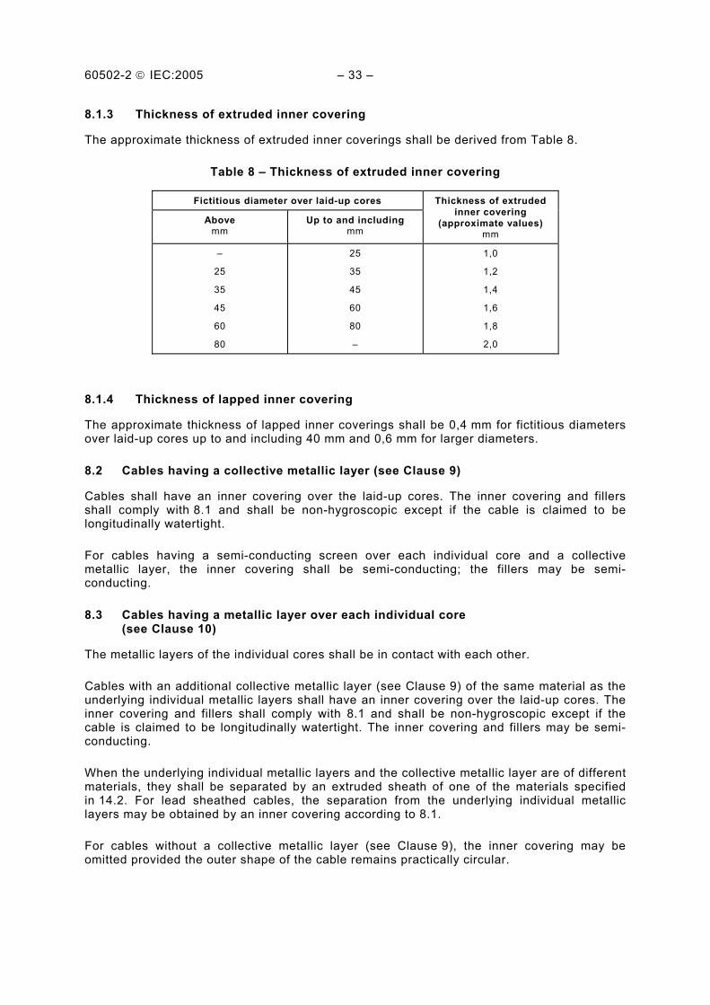
8.1.3 Thickness of extruded inner covering
The approximate thickness of extruded inner coverings shall be derived from Table 8.
Table 8 – Thickness of extruded inner covering
Fictitious diameter over laid-up cores
Above mm
Up to and including mm
Thickness of extruded inner covering
(approximate values) mm
–
25
35
45
60
80
25
35
45
60
80
–
1,0
1,2
1,4
1,6
1,8
2,0
8.1.4 Thickness of lapped inner covering
The approximate thickness of lapped inner coverings shall be 0,4 mm for fictitious diameters over laid-up cores up to and including 40 mm and 0,6 mm for larger diameters.
8.2 Cables having a collective metallic layer (see Clause 9)
Cables shall have an inner covering over the laid-up cores. The inner covering and fillers shall comply with 8.1 and shall be non-hygroscopic except if the cable is claimed to be longitudinally watertight.
For cables having a semi-conducting screen over each individual core and a collective metallic layer, the inner covering shall be semi-conducting; the fillers may be semi-conducting.
8.3 Cables having a metallic layer over each individual core (see Clause 10)
The metallic layers of the individual cores shall be in contact with each other.
Cables with an additional collective metallic layer (see Clause 9) of the same material as the underlying individual metallic layers shall have an inner covering over the laid-up cores. The inner covering and fillers shall comply with 8.1 and shall be non-hygroscopic except if the cable is claimed to be longitudinally watertight. The inner covering and fillers may be semi-conducting.
When the underlying individual metallic layers and the collective metallic layer are of different materials, they shall be separated by an extruded sheath of one of the materials specified in 14.2. For lead sheathed cables, the separation from the underlying individual metallic layers may be obtained by an inner covering according to 8.1.
For cables without a collective metallic layer (see Clause 9), the inner covering may be omitted provided the outer shape of the cable remains practically circular.

60502-2 IEC:2005 – 35 –
9 Metallic layers for single-core and three-core cables
The following types of metallic layers are included in this standard:
a) metallic screen (see Clause 10); b) concentric conductor (see Clause 11); c) metallic sheath (see Clause 12); d) metallic armour (see Clause 13).
The metallic layer(s) shall comprise one or more of the types listed above and shall be non-magnetic when applied to either single-core cables or individual cores of three-core cables.
Measures may be taken to achieve longitudinal watertightness in the region of the metallic layers.
10 Metallic screen
10.1 Construction
The metallic screen shall consist of one or more tapes, or a braid, or a concentric layer of wires or a combination of wires and tape(s).
It may also be a sheath or, in the case of a collective screen, an armour which complies with 10.2.
When choosing the material of the screen, special consideration shall be given to the possibility of corrosion, not only for mechanical safety but also for electrical safety.
Gaps in the screen shall comply with the national regulations and/or standards.
10.2 Requirements
The dimensional, physical and electrical requirements of the metallic screen shall be determined by national regulations and/or standards.
10.3 Metallic screens not associated with semi-conducting layers
Where metallic screens are employed at rated voltage of 3,6/6 (7,2) kV with PVC, EPR and HEPR insulations, these need not be associated with semi-conducting layers.
11 Concentric conductor
11.1 Construction
Gaps in the concentric conductor shall comply with national regulations and/or standards.
When choosing the material of the concentric conductor, special consideration shall be given to the possibility of corrosion, not only for mechanical safety but also for electrical safety.

60502-2 IEC:2005 – 37 –
11.2 Requirements
The dimensional and physical requirements of the concentric conductor and its electrical resistance shall be determined by national regulations and/or standards.
11.3 Application
When a concentric conductor is required, it shall be applied over the inner covering in the case of three-core cables; in the case of single-core cables, it shall be applied either directly over the insulation or over the semi-conducting insulation screen or over a suitable inner covering.
12 Metallic sheath
12.1 Lead sheath
The sheath shall consist of lead or lead alloy and shall be applied as a reasonably tight-fitting seamless tube.
The nominal thickness shall be calculated by the following formula:
a) for all single-core cables or assemblies thereof: tpb = 0,03 Dg + 0,8
b) for all cables with sector-shaped conductors up to and including 8,7/15 kV: tpb = 0,03 Dg + 0,6
c) for all other cables: tpb = 0,03 Dg + 0,7
where tpb is the nominal thickness of the lead sheath, in millimetres; Dg is the fictitious diameter under the lead sheath, in millimetres (rounded to the first
decimal place in accordance with Annex C).
In all cases, the smallest nominal thickness shall be 1,2 mm. Calculated values shall be rounded to the first decimal place (see Annex C).
12.2 Other metallic sheaths
Under consideration.
13 Metallic armour
13.1 Types of metallic armour
The armour types covered by this standard are as follows:
a) flat wire armour; b) round wire armour; c) double tape armour.

60502-2 IEC:2005 – 39 –
13.2 Materials
Round or flat wires shall be of galvanized steel, copper or tinned copper, aluminium or aluminium alloy.
Tapes shall be of steel, galvanized steel, aluminium or aluminium alloy. Steel tapes shall be hot or cold rolled of commercial quality.
In those cases where the steel armour wire layer is required to comply with a minimum conductance, it is permissible to include sufficient copper or tinned copper wires in the armour layer to ensure compliance.
When choosing the material of the armour, special consideration shall be given to the possibility of corrosion, not only for mechanical safety, but also for electrical safety, especially when the armour is used as a screen.
The armour of single-core cables for use on a.c. systems shall consist of non-magnetic material, unless a special construction is chosen.
13.3 Application of armour
13.3.1 Single-core cables
In the case of single-core cables, an inner covering, extruded or lapped, of the thickness specified in 8.1.3 or 8.1.4, shall be applied under the armour if there is no screen.
13.3.2 Three-core cables
When an armour is required in the case of three-core cables, it shall be applied on an inner covering complying with 8.1.
13.3.3 Separation sheath
When the underlying metallic layer and the armour are of different materials, they shall be separated by an extruded sheath of one of the materials specified in 14.2.
When an armour is required for a lead-sheathed cable, it may be applied over a separation sheath or a lapped bedding according to 13.3.4.
If a separation sheath is used, it shall be applied under the armour instead of, or in addition to, the inner covering.
A separation sheath is not required when measures have been taken to achieve longitudinal watertightness in the region of the metallic layers.
The nominal thickness of the separation sheath Ts expressed in millimetres shall be calculated by the following formula:
Ts = 0,02 Du + 0,6
where Du is the fictitious diameter under this sheath, in millimetres, calculated as described in Annex A.
The value resulting from the formula shall be rounded off to the nearest 0,1 mm (see Annex C).
For cables without a lead sheath, the nominal thickness shall be not less than 1,2 mm. For cables where the separation sheath is applied directly over the lead sheath, the nominal thickness shall be not less than 1,0 mm.

60502-2 IEC:2005 – 41 –
13.3.4 Lapped bedding under armour for lead sheathed cables
The lapped bedding applied to the compound coated lead sheath shall consist of either impregnated and compounded paper tapes or a combination of two layers of impregnated and compounded paper tapes followed by one or more layers of compounded fibrous material.
The impregnation of bedding materials may be made with bituminous or other preservative compounds. In case of wire armour, these compounds shall not be applied directly under the wires.
Synthetic tapes may be applied instead of impregnated paper tapes.
The total thickness of the lapped bedding between the lead sheath and the armour after application of the armour shall have an approximate value of 1,5 mm.
13.4 Dimensions of the armour wires and armour tapes
The nominal dimensions of the armour wires and armour tapes shall preferably be one of the following values:
round wires: 0,8 – 1,25 – 1,6 – 2,0 – 2,5 – 3,15 mm diameter;
flat wires: 0,8 mm thickness;
tapes of steel: 0,2 – 0,5 – 0,8 mm thickness;
tapes of aluminium or aluminium alloy: 0,5 – 0,8 mm thickness.
13.5 Correlation between cable diameters and armour dimensions
The nominal diameters of round armour wires and the nominal thicknesses of the armour tapes shall be not less than the values given in Tables 9 and 10 respectively.
Table 9 – Nominal diameter of round armour wires
Fictitious diameter under the armour
Above mm
Up to and including mm
Nominal diameter of armour wire
mm
– 10 15 25 35 60
10 15 25 35 60 –
0,8 1,25 1,6 2,0 2,5 3,15

60502-2 IEC:2005 – 43 –
Table 10 – Nominal thickness of armour tapes
Fictitious diameter under the armour Nominal thickness of tape
Above Up to and including
Steel or galvanized steel
Aluminium or aluminium alloy
mm mm mm mm
– 30 70
30 70 –
0,2 0,5 0,8
0,5 0,5 0,8
For flat wire armour and fictitious diameters under armour greater than 15 mm, the nominal thickness of the flat steel wire shall be 0,8 mm. Cables with fictitious diameters under the armour up to and including 15 mm shall not be armoured with flat wires.
13.6 Round or flat wire armour
The wire armour shall be closed, i.e. with a minimum gap between adjacent wires. An open helix consisting of galvanized steel tape with a nominal thickness of at least 0,3 mm may be provided over flat steel wire armour and over round steel wire armour, if necessary. Tolerances on this steel tape shall comply with 17.7.3.
13.7 Double tape armour
When a tape armour and an inner covering as specified in 8.1 are used, the inner covering shall be reinforced by a taped bedding. The total thickness of the inner covering and the additional taped bedding shall be as given in 8.1 plus 0,5 mm if the armour tape thickness is 0,2 mm, and plus 0,8 mm if the armour tape thickness is more than 0,2 mm.
The total thickness of the inner covering and the additional taped bedding shall be not less than these values by more than 0,2 mm with a tolerance of +20 %.
If a separation sheath is required or if the inner covering is extruded and satisfies the requirements of 13.3.3, the additional taped bedding is not required.
The tape armour shall be applied helically in two layers so that the outer tape is approximately central over the gap of the inner tape. The gap between adjacent turns of each tape shall not exceed 50 % of the width of the tape.
14 Oversheath
14.1 General
All cables shall have an oversheath.
The oversheath is normally black, but a colour other than black may be provided by agreement between the manufacturer and the purchaser, subject to its suitability for the particular conditions under which the cable is to be used.
NOTE A UV stability test is under consideration.
60502-2 IEC:2005 – 45 –
14.2 Material
The oversheath shall consist of a thermoplastic compound (PVC or polyethylene) or an elastomeric compound (polychloroprene, chlorosulfonated polyethylene or similar polymers).
The oversheathing material shall be suitable for the operating temperature in accordance with Table 4.
Chemical additives may be necessary in the oversheath for special purposes, for example termite protection, but they should not include materials harmful to mankind and/or environment.
NOTE Examples of materials1) considered to be undesirable include:
• Aldrin: 1,2,3,4,10,10-hexachloro-1,4,4a,5,8,8a-hexahydro-1,4,5,8-dimethanonaphthalene • Dieldrin:1,2,3,4,10,10-hexachloro-6,7-epoxy-1,4,4a,5,6,7,8,8a-octahydro-1,4,5,8-dimethanonaphthalene • Lindane: Gamma Isomer of 1,2,3,4,5,6-hexachloro-cyclohexane.
14.3 Thickness
Unless otherwise specified the nominal thickness ts expressed in millimetres shall be calculated by the following formula:
ts = 0,035 D + 1,0
where D is the fictitious diameter immediately under the oversheath, in millimetres (see Annex A).
The value resulting from the formula shall be rounded off to the nearest 0,1 mm (see Annex C).
For unarmoured cables and cables with the oversheath not applied directly over the armour, metallic screen or concentric conductor, the nominal thickness shall be not less than 1,4 mm for single-core cables and 1,8 mm for three-core cables.
For cables with the oversheath applied directly over the armour, metallic screen or concentric conductor, the nominal thickness shall be not less than 1,8 mm.
15 Test conditions
15.1 Ambient temperature
Unless otherwise specified in the details for the particular test, tests shall be made at an ambient temperature of (20 ± 15) °C.
15.2 Frequency and waveform of power frequency test voltages
The frequency of the alternating test voltages shall be in the range 49 Hz to 61 Hz. The waveform shall be substantially sinusoidal. The values quoted are r.m.s. values.
15.3 Waveform of impulse test voltages
In accordance with IEC 60230, the impulse wave shall have a virtual front time between 1 µs and 5 µs and a nominal time to half the peak value between 40 µs and 60 µs. In other respects, it shall be in accordance with IEC 60060-1. ___________ 1) Source: Dangerous properties of industrial materials, N.I. Sax, fifth edition, Van Nostrand Reinhold, ISBN 0-442-27373-8.

60502-2 IEC:2005 – 47 –
16 Routine tests
16.1 General
Routine tests are normally carried out on each manufactured length of cable (see 3.2.1). The number of lengths to be tested may however be reduced or an alternative test method adopted, according to agreed quality control procedures.
The routine tests required by this standard are as follows:
a) measurement of the electrical resistance of conductors (see 16.2); b) partial discharge test (see 16.3) on cables having cores with conductor screens and
insulation screens in accordance with 7.1 and 7.2; c) voltage test (see 16.4).
16.2 Electrical resistance of conductors
Resistance measurements shall be made on all conductors of each cable length submitted to the routine tests, including the concentric conductor, if any.
The complete cable length, or a sample from it, shall be placed in the test room, which shall be maintained at a reasonably constant temperature, for at least 12 h before the test. In case of doubt as to whether the conductor temperature is the same as the room temperature, the resistance shall be measured after the cable has been in the test room for 24 h. Alternatively, the resistance can be measured on a sample of conductor conditioned for at least 1 h in a temperature-controlled liquid bath.
The measured value of resistance shall be corrected to a temperature of 20 °C and 1 km length in accordance with the formulae and factors given in IEC 60228.
The d.c. resistance of each conductor at 20 °C shall not exceed the appropriate maximum value specified in IEC 60228. For concentric conductors, the resistance shall comply with national regulations and/or standards.
16.3 Partial discharge test
The partial discharge test shall be carried out in accordance with IEC 60885-3, except that the sensitivity as defined in IEC 60885-3 shall be 10 pC or better.
For three-core cables, the test shall be carried out on all insulated cores, the voltage being applied between each conductor and the screen.
The test voltage shall be raised gradually to and held at 2 U0 for 10 s and then slowly reduced to 1,73 U0.
There shall be no detectable discharge exceeding the declared sensitivity from the test object at 1,73 U0.
NOTE Any partial discharge from the test object may be harmful.
16.4 Voltage test
16.4.1 General
The voltage test shall be made at ambient temperature, using alternating voltage at power frequency.

60502-2 IEC:2005 – 49 –
16.4.2 Test procedure for single-core cables
For single-core cables, the test voltage shall be applied for 5 min between the conductor and the metallic screen.
16.4.3 Test procedure for three-core cables
For three-core cables with individually screened cores, the test voltage shall be applied for 5 min between each conductor and the metallic layer.
For three-core cables without individually screened cores, the test voltage shall be applied for 5 min in succession between each insulated conductor and all the other conductors and collective metallic layers.
Three-core cables may be tested in a single operation by using a three-phase transformer.
16.4.4 Test voltage
The power frequency test voltage shall be 3,5 U0. Values of single-phase test voltage for the standard rated voltages are given in Table 11.
Table 11 – Routine test voltages
Rated voltage U0 kV 3,6 6 8,7 12 18
Test voltage kV 12,5 21 30,5 42 63
If, for three-core cables, the voltage test is carried out with a three-phase transformer, the test voltage between the phases shall be 1,73 times the values given in this table.
In all cases, the test voltage shall be increased gradually to the specified value.
16.4.5 Requirement
No breakdown of the insulation shall occur.
17 Sample tests
17.1 General
The sample tests required by this standard are as follows:
a) conductor examination (see 17.4); b) check of dimensions (see 17.5 to 17.8); c) voltage test for cables of rated voltage above 3,6/6 (7,2) kV (see 17.9); d) hot set test for EPR, HEPR and XLPE insulations and elastomeric sheaths (see 17.10).

60502-2 IEC:2005 – 51 –
17.2 Frequency of sample tests
17.2.1 Conductor examination and check of dimensions
Conductor examination, measurement of the thickness of insulation and sheath and measurement of the overall diameter shall be made on one length from each manufacturing series of the same type and nominal cross-section of cable, but shall be limited to not more than 10 % of the number of lengths in any contract.
17.2.2 Electrical and physical tests
Electrical and physical tests shall be carried out on samples taken from manufactured cables according to agreed quality control procedures. In the absence of such an agreement, for contracts where the total length exceeds 2 km for three-core cables, or 4 km for single-core cables, tests shall be made on the basis of Table 12.
Table 12 – Number of samples for sample tests
Cable length
Multicore cables Single-core cables
Above km
Up to and includingkm
Above km
Up to and including km
Number of samples
2
10
20
10
20
30
4
20
40
20
40
60
1
2
3
etc. etc. etc.
17.3 Repetition of tests
If any sample fails in any of the tests in Clause 17, two further samples shall be taken from the same batch and submitted to the same test or tests in which the original sample failed. If both additional samples pass the tests, all the cables in the batch from which they were taken shall be regarded as complying with the requirements of this standard. If either of the additional samples fails, the batch from which they were taken shall be regarded as failing to comply.
17.4 Conductor examination
Compliance with the requirements for conductor construction of IEC 60228 shall be checked by inspection and by measurement, when practicable.
17.5 Measurement of thickness of insulation and of non-metallic sheaths (including extruded separation sheaths, but excluding inner extruded coverings)
17.5.1 General
The test method shall be in accordance with Clause 8 of IEC 60811-1-1.
Each cable length selected for the test shall be represented by a piece of cable taken from one end after having discarded, if necessary, any portion which may have suffered damage.

60502-2 IEC:2005 – 53 –
17.5.2 Requirements for the insulation
For each piece of core, the smallest value measured shall not fall below 90 % of the nominal value by more than 0,1 mm, i.e.:
tmin ≥ 0,9 tn – 0,1
and additionally :
(tmax – tmin)/ tmax ≤ 0,15
where tmax is the maximum thickness, in millimetres; tmin is the minimum thickness, in millimetres; tn is the nominal thickness, in millimetres.
NOTE tmax and tmin are measured at the same cross-section.
17.5.3 Requirements for the non-metallic sheaths
The piece of sheath shall comply with the following:
a) for unarmoured cables and cables with an oversheath not applied directly over armour, metallic screen or concentric conductor, the smallest value measured shall not fall below 85 % of the nominal value by more than 0,1 mm, i.e.:
tmin ≥ 0,85 tn – 0,1 b) for an oversheath applied directly over armour, metallic screen or concentric conductor
and for a separation sheath, the smallest value measured shall not fall below 80 % of the nominal value by more than 0,2 mm, i.e.:
tmin ≥ 0,8 tn – 0,2
17.6 Measurement of thickness of lead sheath
The minimum thickness of the lead sheath shall be determined by one of the following methods, at the discretion of the manufacturer, and shall not fall below 95 % of the nominal thickness by more than 0,1 mm i.e.:
tmin ≥ 0,95 tn – 0,1
NOTE Methods of measuring thickness of other types of metallic sheath are under consideration.
17.6.1 Strip method
The measurement shall be made with a micrometer with plane faces of 4 mm to 8 mm diameter and an accuracy of ±0,01 mm.
The measurement shall be made on a test piece of sheath about 50 mm in length removed from the completed cable. The piece shall be slit longitudinally and carefully flattened. After cleaning the test piece, a sufficient number of measurements shall be made along the circumference of the sheath and not less than 10 mm away from the edge of the flattened piece to ensure that the minimum thickness is measured.

60502-2 IEC:2005 – 55 –
17.6.2 Ring method
The measurements shall be made with a micrometer having either one flat nose and one ball nose, or one flat nose and a flat rectangular nose 0,8 mm wide and 2,4 mm long. The ball nose or the flat rectangular nose shall be applied to the inside of the ring. The accuracy of the micrometer shall be ±0,01 mm.
The measurements shall be made on a ring of the sheath carefully cut from the sample. The thickness shall be determined at a sufficient number of points around the circumference of the ring to ensure that the minimum thickness is measured.
17.7 Measurement of armour wires and tapes
17.7.1 Measurement on wires
The diameter of round wires and the thickness of flat wires shall be measured by means of a micrometer having two flat noses to an accuracy of ±0,01 mm. For round wires, two measurements shall be made at right angles to each other at the same position and the average of the two values taken as the diameter.
17.7.2 Measurement on tapes
The measurement shall be made with a micrometer having two flat noses of approximately 5 mm in diameter to an accuracy of ± 0,01 mm. For tapes up to 40 mm in width the thickness shall be measured at the centre of the width. For wider tapes the measurements shall be made 20 mm from each edge of the tape and the average of the results taken as the thickness.
17.7.3 Requirements
The dimensions of armour wires and tapes shall not fall below the nominal values given in 13.5 by more than:
– 5 % for round wires; – 8 % for flat wires; – 10 % for tapes.
17.8 Measurement of external diameter
If the measurement of the external diameter of the cable is required as a sample test, it shall be carried out in accordance with Clause 8 of IEC 60811-1-1.
17.9 Voltage test for 4 h
This test is applicable only to cables of rated voltage above 3,6/6 (7,2) kV.
17.9.1 Sampling
The sample shall be a piece of completed cable at least 5 m in length between the test terminations.
17.9.2 Procedure
A power frequency voltage shall be applied for 4 h at ambient temperature between each conductor and the metallic layer(s).

60502-2 IEC:2005 – 57 –
17.9.3 Test voltages
The test voltage shall be 4 U0. Values of the test voltage for the standard rated voltages are given in Table 13.
Table 13 – Sample test voltages
Rated voltage U0 kV 6 8,7 12 18
Test voltage kV 24 35 48 72
The test voltage shall be increased gradually to the specified value and maintained for 4 h.
17.9.4 Requirements
No breakdown of the insulation shall occur.
17.10 Hot set test for EPR, HEPR and XLPE insulations and elastomeric sheaths
17.10.1 Procedure
The sampling and test procedure shall be carried out in accordance with Clause 9 of IEC 60811-2-1, employing the conditions given in Tables 19 and 23.
17.10.2 Requirements
The test results shall comply with the requirements given in Table 19, for EPR, HEPR and XLPE insulations and in Table 23 for SE1 sheaths.
18 Type tests, electrical
When type tests have been successfully performed on a type of cable covered by this standard with a specific conductor cross-sectional area and rated voltage, type approval shall be accepted as valid for cables of the same type with other conductor cross-sectional areas and/or rated voltages, provided the following three conditions are all satisfied:
a) the same materials, i.e. insulation and semi-conducting screens, and manufacturing process are used;
b) the conductor cross-sectional area is not larger than that of the tested cable, with the exception that all cross-sectional areas up to and including 630 mm2 are approved when the cross-sectional area of the previously tested cable is in the range of 95 mm2 to 630 mm2 inclusive;
c) the rated voltage is not higher than that of the tested cable.
Approval shall be independent of the conductor material.
18.1 Cables having conductor screens and insulation screens
A sample of completed cable 10 m to 15 m in length shall be subjected to the tests listed in 18.1.1.
With the exception of the provisions of 18.1.2 all the tests listed in 18.1.1 shall be applied successively to the same sample.

60502-2 IEC:2005 – 59 –
In three-core cables, each test or measurement shall be carried out on all cores.
Measurement of resistivity of semi-conducting screens described in 18.1.9 shall be made on a separate sample.
18.1.1 Sequence of tests
The normal sequence of tests shall be as follows:
a) bending test, followed by a partial discharge test (see 18.1.3 and 18.1.4);
b) tan δ measurement (see 18.1.2 and 18.1.5); c) heating cycle test, followed by a partial discharge test (see 18.1.6); d) impulse test, followed by a voltage test (see 18.1.7); e) voltage test for 4 h (see 18.1.8).
18.1.2 Special provisions
Measurement of tan δ may be carried out on a different sample from the sample used for the normal sequence of tests listed in 18.1.1.
Measurement of tan δ is not required on cables with rated voltage below 6/10 (12) kV.
A new sample may be taken for test e), provided this test sample is submitted previously to tests a) and c) listed in 18.1.1.
18.1.3 Bending test
The sample shall be bent around a test cylinder (for example, the hub of a drum) at ambient temperature for at least one complete turn. It shall then be unwound and the process repeated, except that the bending of the sample shall be in the reverse direction without axial rotation.
This cycle of operation shall be carried out three times.
The diameter of the test cylinder shall be
– for cables with a lead sheath or with an overlapped metal foil longitudinally applied: - 25 (d + D) ± 5 % for single-core cables; - 20 (d + D) ± 5 % for three-core cables;
– for other cables: - 20 (d + D) ± 5 % for single-core cables; - 15 (d + D) ± 5 % for three-core cables. where D is the actual external diameter of the cable sample, in millimetres, measured
according to 17.8; d is the actual diameter of the conductor, in millimetres.

60502-2 IEC:2005 – 61 –
If the conductor is not circular:
d = 1,13 S
where S is the nominal cross-section, in square millimetres.
On completion of this test, the sample shall be subjected to a partial discharge test and shall comply with the requirements given in 18.1.4.
18.1.4 Partial discharge test
The partial discharge test shall be carried out in accordance with IEC 60885-3, the sensitivity being 5 pC or better.
The test voltage shall be raised gradually to and held at 2 U0 for 10 s and then slowly reduced to 1,73 U0.
There shall be no detectable discharge exceeding the declared sensitivity from the test object at 1,73 U0.
NOTE Any partial discharge from the test object may be harmful.
18.1.5 Tan δ measurement for cables of rated voltage 6/10 (12) kV and above
The sample of completed cable shall be heated by one of the following methods: the sample shall be placed either in a tank of liquid or in an oven, or a heating current shall be passed through either the metallic screen or the conductor or both.
The sample shall be heated until the conductor reaches a temperature which shall be 5 °C to 10 °C above the maximum conductor temperature in normal operation.
In each method, the temperature of the conductor shall be determined either by measuring the conductor resistance or by a suitable temperature measuring device in the bath or oven or on the surface of the screen or on an identically heated reference cable.
The tan δ shall be measured with an alternating voltage of at least 2 kV at the temperature specified above.
The measured values shall not be higher than those given in Table 15.
18.1.6 Heating cycle test
The sample, which has been subjected to the previous tests, shall be laid out on the floor of the test room and heated by passing a current through the conductor, until the conductor reaches a steady temperature 5 °C to 10 °C above the maximum conductor temperature in normal operation.
For three-core cables, the heating current shall be passed through all conductors.
The heating cycle shall be of at least 8 h duration. The conductor temperature shall be maintained within the stated temperature limits for at least 2 h of each heating period. This shall be followed by at least 3 h of natural cooling in air to a conductor temperature within 10 K of ambient temperature.
This cycle shall be carried out 20 times.

60502-2 IEC:2005 – 63 –
After the last cycle, the sample shall be subjected to a partial discharge test and shall comply with the requirements given in 18.1.4.
18.1.7 Impulse test followed by a voltage test
This test shall be performed on the sample at a conductor temperature 5 °C to 10 °C above the maximum conductor temperature in normal operation.
The impulse voltage shall be applied according to the procedure given in IEC 60230 and shall have a peak value as given in Table 14.
Table 14 – Impulse voltages
Rated voltage U0/U (Um) KV 3,6/6 (7,2) 6/10 (12) 8,7/15 (17,5) 12/20 (24) 18/30 (36)
Test voltage (peak) KV 60 75 95 125 170
Each core of the cable shall withstand without failure 10 positive and 10 negative voltage impulses.
After the impulse test, each core of the cable sample shall be subjected, at ambient temperature, to a power frequency voltage test for 15 min. The test voltage shall be as specified in Table 11. No breakdown of the insulation shall occur.
18.1.8 Voltage test for 4 h
This test shall be made at ambient temperature. A power frequency voltage shall be applied for 4 h to the sample between conductor(s) and screen(s).
The test voltage shall be 4 U0. The voltage shall be increased gradually to the specified value. No breakdown of the insulation shall occur.
18.1.9 Resistivity of semi-conducting screens
The resistivity of the extruded semi-conducting screens applied over the conductor and over the insulation shall be determined by measurements on test pieces taken from the core of a sample of cable as made and a sample of cable, which has been subjected to the ageing treatment to test the compatibility of component materials specified in 19.5.
18.1.9.1 Procedure
The test procedure shall be in accordance with Annex D.
The measurements shall be made at a temperature within ±2 °C of the maximum conductor temperature in normal operation.
18.1.9.2 Requirements
The resistivity, both before and after ageing, shall not exceed the following:
– conductor screen: 1 000 m⋅Ω , – insulation screen: 500 m⋅Ω .

60502-2 IEC:2005 – 65 –
18.2 Cables of rated voltage 3,6/6 (7,2) kV having unscreened insulation
Each core of a sample of completed cable 10 m to 15 m in length shall be subjected to the following tests, applied successively:
a) insulation resistance measurement at ambient temperature (see 18.2.1); b) insulation resistance measurement at maximum conductor temperature in normal
operation (see 18.2.2); c) voltage test for 4 h (see 18.2.3).
The cables shall also be subjected to an impulse test on a separate sample of completed cable, 10 m to 15 m in length (see 18.2.4).
18.2.1 Insulation resistance measurement at ambient temperature
18.2.1.1 Procedure
This test shall be made on the sample length before any other electrical test.
All outer coverings shall be removed and the cores shall be immersed in water at ambient temperature for at least 1 h before the test.
The d.c. test voltage shall be 80 V to 500 V and shall be applied for a sufficient time to reach reasonably steady measurement, but for not less than 1 min and not more than 5 min.
The measurement shall be made between each conductor and the water.
If requested, measurement may be confirmed at a temperature of (20 ± 1) °C.
18.2.1.2 Calculations
The volume resistivity shall be calculated from the measured insulation resistance by the following formula:
ρ = 2 × × ×π l R
Ddln
where
ρ is the volume resistivity, in ohms . centimetres; R is the measured insulation resistance, in ohms; l is the length of the cable, in centimetres; D is the outer diameter of the insulation, in millimetres; d is the inner diameter of the insulation, in millimetres.
The ''insulation resistance constant Ki" expressed in megohms · kilometres may also be calculated, using the formula:
Kl R
Dd
ilg
= 10
= 10 0,367 × ×
× ×−
−11
11 ρ
NOTE For the cores of shaped conductors, the ratio D/d is the ratio of the perimeter over the insulation to the perimeter over the conductor.

60502-2 IEC:2005 – 67 –
18.2.1.3 Requirements
The values calculated from the measurements shall be not less than those specified in Table 15.
18.2.2 Insulation resistance measurement at maximum conductor temperature
18.2.2.1 Procedure
The cores of the cable sample shall be immersed in water at a temperature within ±2 °C of the maximum conductor temperature in normal operation for at least 1 h before the test.
The d.c. test voltage shall be 80 V to 500 V and shall be applied for a sufficient time to reach reasonably steady measurement, but for not less than 1 min and not more than 5 min.
The measurement shall be made between each conductor and the water.
18.2.2.2 Calculations
The volume resistivity and/or the insulation resistance constant shall be calculated from the insulation resistance by the formulae given in 18.2.1.2.
18.2.2.3 Requirements
The values calculated from the measurements shall be not less than those specified in Table 15.
18.2.3 Voltage test for 4 h
18.2.3.1 Procedure
The cores of the cable sample shall be immersed in water at ambient temperature for at least 1 h.
A power frequency voltage equal to 4 U0 shall then be gradually applied and maintained continuously for 4 h between each conductor and the water.
18.2.3.2 Requirements
No breakdown of the insulation shall occur.
18.2.4 Impulse test
18.2.4.1 Procedure
This test shall be performed on the sample at a conductor temperature 5 °C to 10 °C above the maximum conductor temperature in normal operation.
The impulse voltage shall be applied according to the procedure given in IEC 60230 and shall have a peak value of 60 kV.
Each series of impulses shall be applied in turn between each phase conductor and all the other conductors connected together and to earth.

60502-2 IEC:2005 – 69 –
18.2.4.2 Requirements
Each core of the cable shall withstand without failure 10 positive and 10 negative voltage impulses.
19 Type tests, non-electrical
The non-electrical type tests required by this standard are given in Table 16.
19.1 Measurement of thickness of insulation
19.1.1 Sampling
One sample shall be taken from each insulated cable core.
19.1.2 Procedure
The measurements shall be made as described in 8.1 of IEC 60811-1-1.
19.1.3 Requirements
See 17.5.2.
19.2 Measurement of thickness of non-metallic sheaths (including extruded separation sheaths, but excluding inner coverings)
19.2.1 Sampling
One sample of cable shall be taken.
19.2.2 Procedure
The measurements shall be made as described in 8.2 of IEC 60811-1-1.
19.2.3 Requirements
See 17.5.3.
19.3 Tests for determining the mechanical properties of insulation before and after ageing
19.3.1 Sampling
Sampling and the preparation of the test pieces shall be carried out as described in 9.1 of IEC 60811-1-1.
19.3.2 Ageing treatments
The ageing treatments shall be carried out as described in 8.1 of IEC 60811-1-2 under the conditions specified in Table 17.
19.3.3 Conditioning and mechanical tests
Conditioning and the measurement of mechanical properties shall be carried out as described in 9.1 of IEC 60811-1-1.

60502-2 IEC:2005 – 71 –
19.3.4 Requirements
The test results for unaged and aged test pieces shall comply with the requirements given in Table 17.
19.4 Tests for determining the mechanical properties of non-metallic sheaths before and after ageing
19.4.1 Sampling
Sampling and the preparation of the test pieces shall be carried out as described in 9.2 of IEC 60811-1-1.
19.4.2 Ageing treatments
The ageing treatments shall be carried out as described in 8.1 of IEC 60811-1-2, under the conditions specified in Table 20.
19.4.3 Conditioning and mechanical tests
Conditioning and the measurement of mechanical properties shall be carried out as described in 9.2 of IEC 60811-1-1.
19.4.4 Requirements
The test results for unaged and aged test pieces shall comply with the requirements given in Table 20.
19.5 Additional ageing test on pieces of completed cables
19.5.1 General
This test is intended to check that the insulation and non-metallic sheaths are not liable to deteriorate in operation due to contact with other components in the cable.
The test is applicable to cables of all types.
19.5.2 Sampling
Samples shall be taken from the completed cable as described in 8.1.4 of IEC 60811-1-2.
19.5.3 Ageing treatment
The ageing treatment of the pieces of cable shall be carried out in an air oven, as described in 8.1.4 of IEC 60811-1-2, under the following conditions:
– temperature: (10 ± 2) °C above the maximum conductor temperature of the cable in normal operation (see Table 17);
– duration: 7 x 24 h.
19.5.4 Mechanical tests
Test pieces of insulation and oversheath from the aged pieces of cable shall be prepared and subjected to mechanical tests as described in 8.1.4 of IEC 60811-1-2.

60502-2 IEC:2005 – 73 –
19.5.5 Requirements
The variations between the median values of tensile strength and elongation-at-break after ageing and the corresponding values obtained without ageing (see 19.3 and 19.4) shall not exceed the values applying to the test after ageing in an air oven specified in Table 17 for insulations and Table 20 for non-metallic sheaths.
19.6 Loss of mass test on PVC sheaths of type ST2
19.6.1 Procedure
The sampling and test procedure shall be in accordance with 8.2 of IEC 60811-3-2.
19.6.2 Requirements
The test results shall comply with the requirements given in Table 21.
19.7 Pressure test at high temperature on insulations and non-metallic sheaths
19.7.1 Procedure
The pressure test at high temperature shall be carried out in accordance with Clause 8 of IEC 60811-3-1, employing the test conditions given in the test method and in Tables 18, 21 and 22.
19.7.2 Requirements
The test results shall comply with the requirements given in Clause 8 of IEC 60811-3-1.
19.8 Test on PVC insulation and sheaths at low temperatures
19.8.1 Procedure
The sampling and test procedures shall be in accordance with Clause 8 of IEC 60811-1-4, employing the test temperature specified in Tables 18 and 21.
19.8.2 Requirements
The results of the test shall comply with the requirements given in Clause 8 of IEC 60811-1-4.
19.9 Test for resistance of PVC insulation and sheaths to cracking (heat shock test)
19.9.1 Procedure
The sampling and test procedure shall be in accordance with Clause 9 of IEC 60811-3-1, the test temperature and duration being in accordance with Tables 18 and 21.
19.9.2 Requirements
The results of the tests shall comply with the requirements given in Clause 9 of IEC 60811-3-1.

60502-2 IEC:2005 – 75 –
19.10 Ozone resistance test for EPR and HEPR insulations
19.10.1 Procedure
The sampling and test procedure shall be carried out in accordance with Clause 8 of IEC 60811-2-1. The ozone concentration and test duration shall be in accordance with Table 19.
19.10.2 Requirements
The results of the test shall comply with the requirements given in Clause 8 of IEC 60811-2-1.
19.11 Hot set test for EPR, HEPR and XLPE insulations and elastomeric sheaths
The sampling and test procedure shall be carried out in accordance with 17.10 and shall comply with its requirements.
19.12 Oil immersion test for elastomeric sheaths
19.12.1 Procedure
The sampling and test procedure shall be carried out in accordance with Clause 10 of IEC 60811-2-1 employing the conditions given in Table 23.
19.12.2 Requirements
The results of the test shall comply with the requirements given in Table 23.
19.13 Water absorption test on insulation
19.13.1 Procedure
The sampling and test procedure shall be carried out in accordance with 9.1 or 9.2 of IEC 60811-1-3 employing the conditions specified in Tables 18 or 19 respectively.
19.13.2 Requirements
The results of the test shall comply with the requirements specified in Tables 18 or 19.
19.14 Flame spread test on single cables
This test is only applicable to cables having sheaths of ST1, ST2 or SE1 compound and shall be carried out on such cables only when specially required.
The test method and requirements shall be those specified in IEC 60332-1-2.
19.15 Measurement of carbon black content of black PE oversheaths
19.15.1 Procedure
The sampling and test procedure shall be carried out in accordance with Clause 11 of IEC 60811-4-1.
19.15.2 Requirements
The results of the test shall comply with the requirements of Table 22.
60502-2 IEC:2005 – 77 –
19.16 Shrinkage test for XLPE insulation
19.16.1 Procedure
The sampling and test procedure shall be carried out in accordance with Clause 10 of IEC 60811-1-3 under the conditions specified in Table 19.
19.16.2 Requirements
The results of the test shall comply with the requirements of Table 19.
19.17 Thermal stability test for PVC insulation
19.17.1 Procedure
The sampling and test procedure shall be carried out in accordance with Clause 9 of IEC 60811-3-2 under the conditions specified in Table 18.
19.17.2 Requirements
The results of the test shall comply with the requirements of Table 18.
19.18 Determination of hardness of HEPR insulation
19.18.1 Procedure
The sampling and test procedure shall be carried out in accordance with Annex E.
19.18.2 Requirements
The results of the test shall comply with the requirements of Table 19.
19.19 Determination of the elastic modulus of HEPR insulation
19.19.1 Procedure
Sampling, preparation of the test pieces and the test procedure shall be carried out in accordance with Clause 9 of IEC 60811-1-1.
The loads required for 150 % elongation shall be measured. The corresponding stresses shall be calculated by dividing the loads measured by the cross-sectional areas of the unstretched test pieces. The ratios of the stresses to strains shall be determined to obtain the elastic moduli at 150 % elongation.
The elastic modulus shall be the median value.
19.19.2 Requirements
The results of the test shall comply with the requirements of Table 19.
19.20 Shrinkage test for PE oversheaths
19.20.1 Procedure
The sampling and test procedure shall be carried out in accordance with Clause 11 of IEC 60811-1-3 under the conditions specified in Table 22.

60502-2 IEC:2005 – 79 –
19.20.2 Requirements
The results of the test shall comply with the requirements of Table 22.
19.21 Strippability test for insulation screen
This test shall be carried out when the manufacturer claims that the extruded semiconducting insulation screen is strippable.
19.21.1 Procedure
The test shall be performed three times on both unaged and aged samples, using either three separate pieces of cable or one piece of cable at three positions around the circumference, spaced at approximately 120°.
Core lengths of at least 250 mm shall be taken from the cable to be tested, before and after being aged according to 19.5.3.
Two cuts shall be made in the extruded semiconducting insulation screen of each sample, longitudinally from end to end and radially down to the insulation, the cuts being (10 ± 1) mm apart and parallel to each other.
After removing approximately 50 mm length of the 10 mm strip by pulling it in a direction parallel to the core (i.e. a stripping angle of approximately 180°), the core shall be mounted vertically in a tensile machine with one end of the core held in one grip and the 10 mm strip in the other.
The force to separate the 10 mm strip from the insulation, removing a length of at least 100 mm, shall be measured at a stripping angle of approximately 180° using a pulling speed of (250 ± 50) mm/min.
The test shall be carried out at a temperature of (20 ± 5) °C.
For unaged and aged samples, the stripping force values shall be continuously recorded.
19.21.2 Requirements
The force required to remove the extruded semiconducting screen from the insulation shall be not less than 4 N and not more than 45 N, before and after ageing.
The insulation surface shall not be damaged and no trace of the semiconducting screen shall remain on the insulation.
19.22 Water penetration test
The water penetration test shall be applied to those designs of cable where the manufacturer claims that barriers to longitudinal water penetration have been included. The test is designed to meet the requirements for buried cables and is not intended to apply to cables which are constructed for use as submarine cables.
The test is applicable to the following cable designs:
a) a barrier is included which prevents longitudinal water penetration in the region of the metallic layers;
b) a barrier is included which prevents longitudinal water penetration along the conductor.
The apparatus, sampling and test procedure shall be in accordance with Annex F.
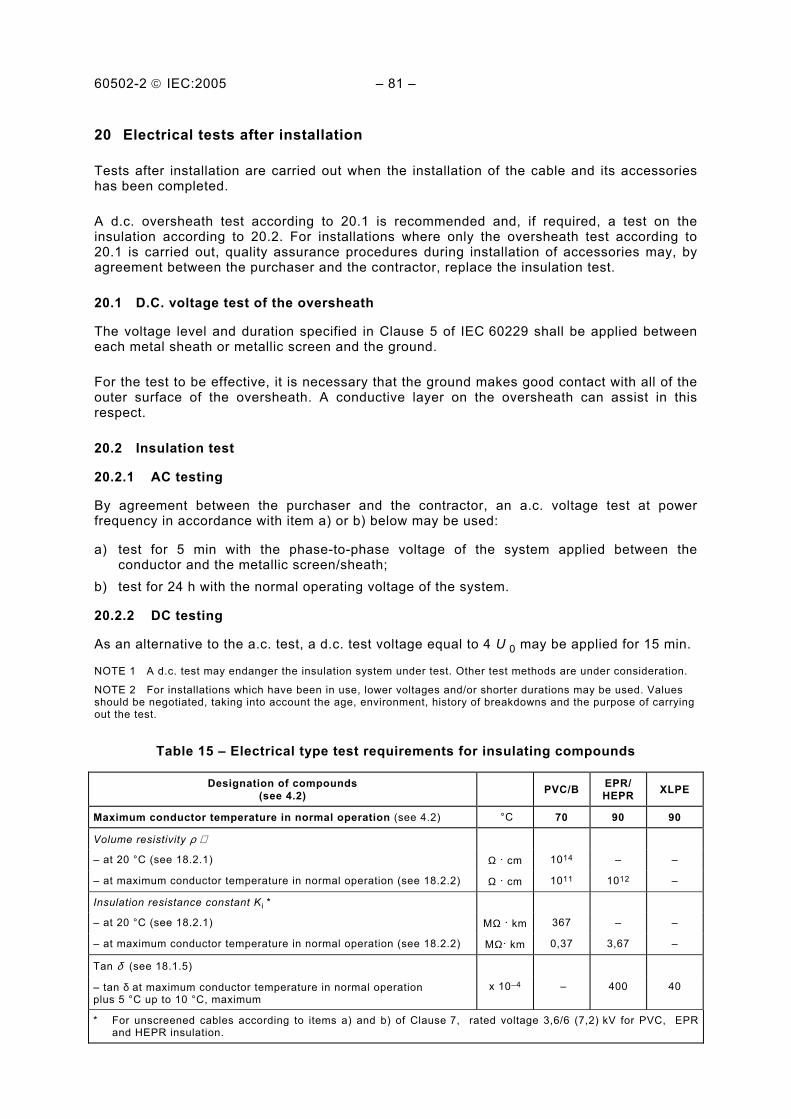
60502-2 IEC:2005 – 81 –
20 Electrical tests after installation
Tests after installation are carried out when the installation of the cable and its accessories has been completed.
A d.c. oversheath test according to 20.1 is recommended and, if required, a test on the insulation according to 20.2. For installations where only the oversheath test according to 20.1 is carried out, quality assurance procedures during installation of accessories may, by agreement between the purchaser and the contractor, replace the insulation test.
20.1 D.C. voltage test of the oversheath
The voltage level and duration specified in Clause 5 of IEC 60229 shall be applied between each metal sheath or metallic screen and the ground.
For the test to be effective, it is necessary that the ground makes good contact with all of the outer surface of the oversheath. A conductive layer on the oversheath can assist in this respect.
20.2 Insulation test
20.2.1 AC testing
By agreement between the purchaser and the contractor, an a.c. voltage test at power frequency in accordance with item a) or b) below may be used:
a) test for 5 min with the phase-to-phase voltage of the system applied between the conductor and the metallic screen/sheath;
b) test for 24 h with the normal operating voltage of the system.
20.2.2 DC testing
As an alternative to the a.c. test, a d.c. test voltage equal to 4 U 0 may be applied for 15 min.
NOTE 1 A d.c. test may endanger the insulation system under test. Other test methods are under consideration.
NOTE 2 For installations which have been in use, lower voltages and/or shorter durations may be used. Values should be negotiated, taking into account the age, environment, history of breakdowns and the purpose of carrying out the test.
Table 15 – Electrical type test requirements for insulating compounds
Designation of compounds (see 4.2)
PVC/B EPR/ HEPR XLPE
Maximum conductor temperature in normal operation (see 4.2) °C 70 90 90
Volume resistivity ρ ∗
– at 20 °C (see 18.2.1) Ω . cm 1014 – –
– at maximum conductor temperature in normal operation (see 18.2.2) Ω . cm 1011 1012 –
Insulation resistance constant K i *
– at 20 °C (see 18.2.1) MΩ . km 367 – –
– at maximum conductor temperature in normal operation (see 18.2.2) MΩ. km 0,37 3,67 –
Tan δ (see 18.1.5)
– tan δ at maximum conductor temperature in normal operation plus 5 °C up to 10 °C, maximum
x 10–4 – 400 40
* For unscreened cables according to items a) and b) of Clause 7, rated voltage 3,6/6 (7,2) kV for PVC, EPR and HEPR insulation.
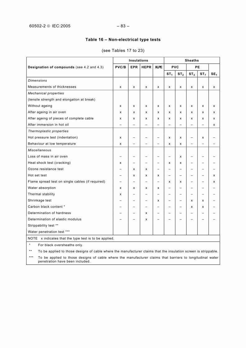
60502-2 IEC:2005 – 83 –
Table 16 – Non-electrical type tests
(see Tables 17 to 23)
Insulations Sheaths
Designation of compounds (see 4.2 and 4.3) PVC/B EPR HEPR XLPE PVC PE
ST1 ST2 ST3 ST7 SE1
Dimensions
Measurements of thicknesses x x x x x x x x x
Mechanical properties
(tensile strength and elongation at break)
Without ageing x x x x x x x x x
After ageing in air oven x x x x x x x x x
After ageing of pieces of complete cable x x x x x x x x x
After immersion in hot oil – – – – – – – – x
Thermoplastic properties
Hot pressure test (indentation) x – – – x x – x –
Behaviour at low temperature x – – – x x – – –
Miscellaneous
Loss of mass in air oven – – – – – x – – –
Heat shock test (cracking) x – – – x x – – –
Ozone resistance test – x x – – – – – –
Hot set test – x x x – – – – x
Flame spread test on single cables (if required) – – – – x x – – x
Water absorption x x x x – – – – –
Thermal stability x – – – – – – – –
Shrinkage test – – – x – – x x –
Carbon black content * – – – – – – x x –
Determination of hardness – – x – – – – – –
Determination of elastic modulus – – x – – – – – –
Strippability test **
Water penetration test ***
NOTE x indicates that the type test is to be applied.
* For black oversheaths only.
** To be applied to those designs of cable where the manufacturer claims that the insulation screen is strippable.
*** To be applied to those designs of cable where the manufacturer claims that barriers to longitudinal water penetration have been included.

60502-2 IEC:2005 – 85 –
Table 17 – Test requirements for mechanical characteristics of insulating compounds (before and after ageing)
Designation of compounds (see 4.2) PVC/B EPR HEPR XLPE
Maximum conductor temperature in normal operation (see 4.2) °C 70 90 90 90
Without ageing (IEC 60811-1-1, 9.1)
Tensile strength, minimum N/mm2 12,5 4,2 8,5 12,5
Elongation-at-break, minimum % 125 200 200 200
After ageing in air oven (IEC 60811-1-2, 8.1)
After ageing without conductor
Treatment:
– temperature – tolerance – duration
°C °C h
100 ±2
168
135 ±3
168
135 ±3
168
135 ±3
168
Tensile strength:
a) value after ageing, minimum b) variation*, maximum
N/mm2
% 12,5 ±25
– ±30
– ±30
– ±25
Elongation-at-break: a) value after ageing, minimum b) variation*, maximum
% %
125 ±25
–
±30
–
±30
–
±25
* Variation: difference between the median value obtained after ageing and the median value obtained without ageing expressed as a percentage of the latter.
Table 18 – Test requirements for particular characteristics for PVC insulating compound
Designation of compound (see 4.2 and 4.3) PVC/B
Use of the PVC compound Insulation
Pressure test at high temperature (IEC 60811-3-1, Clause 8)
Temperature (tolerance ±2 °C) °C 80
Behaviour at low temperature * (IEC 60811-1-4, Clause 8)
Test to be carried out without previous ageing:
– cold bending test for diameter <12,5 mm – temperature (tolerance ±2 °C)
°C
–5
Cold elongation test on dumb-bells:
– temperature (tolerance ±2 °C) °C –5
Heat shock test (IEC 60811-3-1, Clause 9)
Temperature (tolerance ±3 °C) °C 150
Duration h 1
Thermal stability (IEC 60811-3-2, Clause 9)
Temperature (tolerance ±0,5 °C) °C 200
Minimum time min 100
Water absorption (IEC 60811-1-3, 9.1)
Electrical method:
Temperature (tolerance ±2 °C) °C 70
Duration h 240
* Due to climatic conditions, national standards may require the use of a lower temperature.
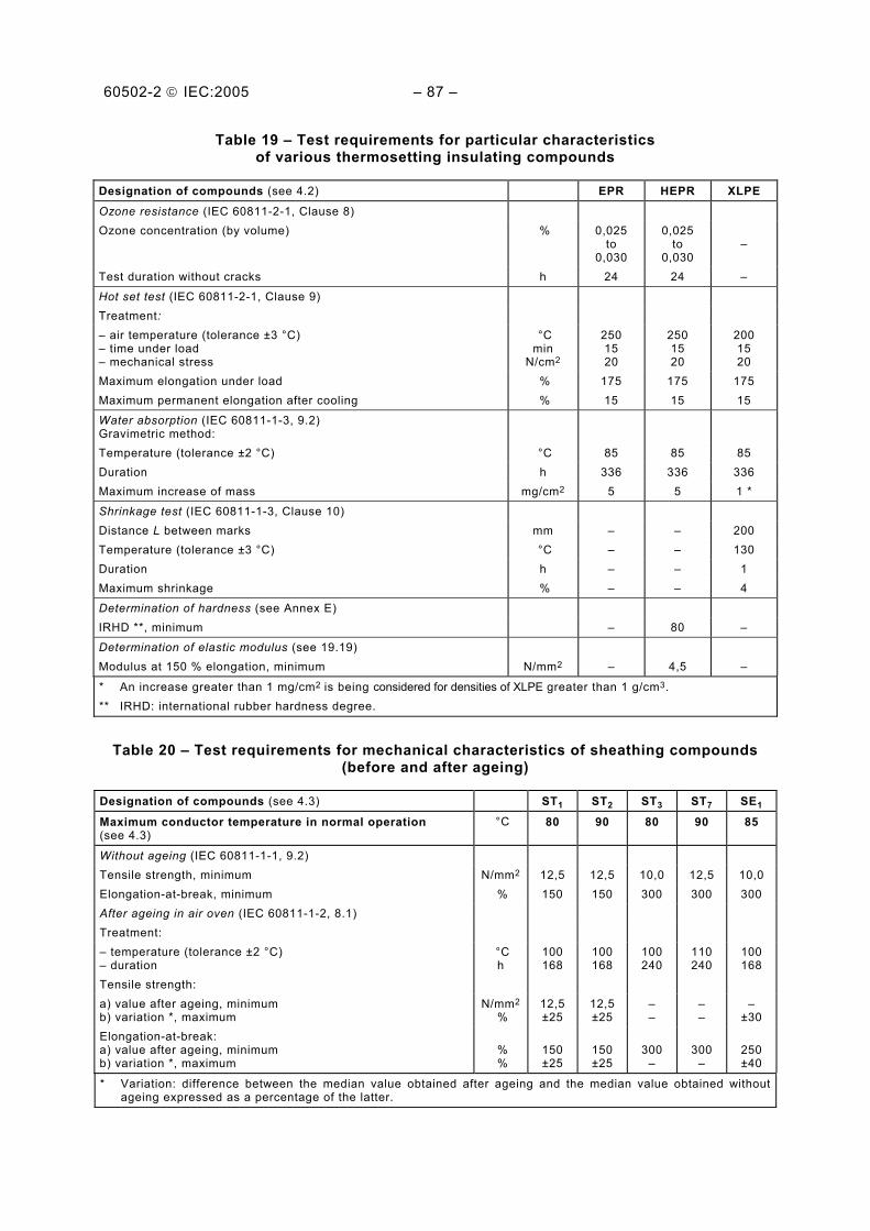
60502-2 IEC:2005 – 87 –
Table 19 – Test requirements for particular characteristics of various thermosetting insulating compounds
Designation of compounds (see 4.2) EPR HEPR XLPE
Ozone resistance (IEC 60811-2-1, Clause 8) Ozone concentration (by volume) % 0,025
to 0,030
0,025 to
0,030
–
Test duration without cracks h 24 24 –
Hot set test (IEC 60811-2-1, Clause 9) Treatment: – air temperature (tolerance ±3 °C) – time under load – mechanical stress
°C min
N/cm2
250 15 20
250 15 20
200 15 20
Maximum elongation under load % 175 175 175 Maximum permanent elongation after cooling % 15 15 15
Water absorption (IEC 60811-1-3, 9.2) Gravimetric method:
Temperature (tolerance ±2 °C) °C 85 85 85 Duration h 336 336 336 Maximum increase of mass mg/cm2 5 5 1 *
Shrinkage test (IEC 60811-1-3, Clause 10) Distance L between marks mm – – 200 Temperature (tolerance ±3 °C) °C – – 130 Duration h – – 1 Maximum shrinkage % – – 4
Determination of hardness (see Annex E) IRHD **, minimum – 80 –
Determination of elastic modulus (see 19.19) Modulus at 150 % elongation, minimum N/mm2 – 4,5 –
* An increase greater than 1 mg/cm2 is being considered for densities of XLPE greater than 1 g/cm3. ** IRHD: international rubber hardness degree.
Table 20 – Test requirements for mechanical characteristics of sheathing compounds (before and after ageing)
Designation of compounds (see 4.3) ST1 ST2 ST3 ST7 SE1
Maximum conductor temperature in normal operation (see 4.3)
°C 80 90 80 90 85
Without ageing (IEC 60811-1-1, 9.2) Tensile strength, minimum N/mm2 12,5 12,5 10,0 12,5 10,0 Elongation-at-break, minimum % 150 150 300 300 300 After ageing in air oven (IEC 60811-1-2, 8.1) Treatment: – temperature (tolerance ±2 °C) – duration
°C h
100 168
100 168
100 240
110 240
100 168
Tensile strength: a) value after ageing, minimum b) variation *, maximum
N/mm2
% 12,5±25
12,5 ±25
– –
– –
– ±30
Elongation-at-break: a) value after ageing, minimum b) variation *, maximum
% %
150 ±25
150 ±25
300
–
300
–
250 ±40
* Variation: difference between the median value obtained after ageing and the median value obtained without ageing expressed as a percentage of the latter.

60502-2 IEC:2005 – 89 –
Table 21 – Test requirements for particular characteristics for PVC sheathing compounds
Designation of compound (see 4.2 and 4.3) ST1 ST2
Use of the PVC compound Sheath
Loss of mass in air oven (IEC 60811-3-2, 8.2) Treatment: – temperature (tolerance ±2 °C) – duration
°C h
– –
100 168
Maximum loss of mass mg/cm2 – 1,5
Pressure test at high temperature (IEC 60811-3-1, Clause 8) Temperature (tolerance ±2 °C) °C 80 90
Behaviour at low temperature * (IEC 60811-1-4, Clause 8) Test to be carried out without previous ageing: – cold bending test for diameter <12,5 mm – temperature (tolerance ±2 °C)
°C
–15
–15
Cold elongation test on dumb-bells: – temperature (tolerance ±2 °C) °C –15 –15 Cold impact test: – temperature (tolerance ±2 °C) °C –15 –15
Heat shock test (IEC 60811-3-1, Clause 9) Temperature (tolerance ±3 °C) °C 150 150 Duration h 1 1
* Due to climatic conditions, national standards may require the use of a lower temperature.
Table 22 – Test requirements for particular characteristics of PE (thermoplastic polyethylene) sheathing compounds
Designation of compounds (see 4.3) ST3 ST7
Density * (IEC 60811-1-3, Clause 8)
Carbon black content (for black oversheaths only) (IEC 60811-4-1, Clause 11)
Nominal value % 2,5 2,5
Tolerance % ±0,5 ±0,5
Shrinkage test (IEC 60811-1-3, Clause 11)
Temperature (tolerance ±2 °C) °C 80 80
Heating, duration h 5 5
Heating cycles 5 5
Maximum shrinkage % 3 3
Pressure test at high temperature (IEC 60811-3-1, 8.2)
Temperature (tolerance ±2 °C) °C – 110
* The measurement of density is only required for the purpose of other tests.
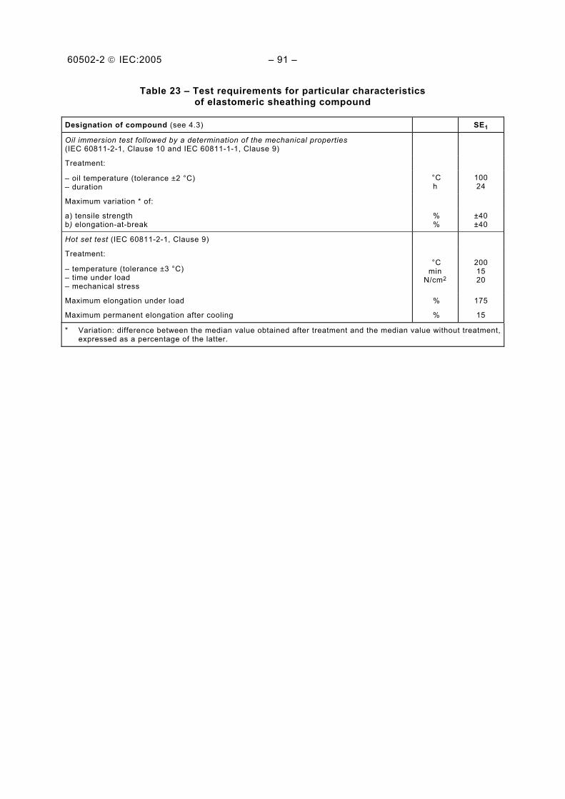
60502-2 IEC:2005 – 91 –
Table 23 – Test requirements for particular characteristics of elastomeric sheathing compound
Designation of compound (see 4.3) SE1
Oil immersion test followed by a determination of the mechanical properties (IEC 60811-2-1, Clause 10 and IEC 60811-1-1, Clause 9)
Treatment:
– oil temperature (tolerance ±2 °C) – duration
°C h
100 24
Maximum variation * of:
a) tensile strength b) elongation-at-break
% %
±40 ±40
Hot set test (IEC 60811-2-1, Clause 9)
Treatment:
– temperature (tolerance ±3 °C) – time under load – mechanical stress
°C min
N/cm2
200 15 20
Maximum elongation under load % 175
Maximum permanent elongation after cooling % 15
* Variation: difference between the median value obtained after treatment and the median value without treatment, expressed as a percentage of the latter.

60502-2 IEC:2005 – 93 –
Annex A (normative)
Fictitious calculation method for determination of dimensions
of protective coverings
The thickness of cable coverings, such as sheaths and armour, has usually been related to nominal cable diameters by means of "step-tables''.
This sometimes causes problems. The calculated nominal diameters are not necessarily the same as the actual values achieved in production. In borderline cases, queries can arise if the thickness of a covering does not correspond to the actual diameter because the calculated diameter is slightly different. Variations in shaped conductor dimensions between manufacturers and different methods of calculation cause differences in nominal diameters and may therefore lead to variations in the thicknesses of coverings used on the same basic design of cable.
To avoid these difficulties, the fictitious calculation method shall be used. The idea is to ignore the shape and degree of compaction of conductors and to calculate fictitious diameters from formulae based on the cross-sectional area of conductors, nominal insulation thickness and number of cores. Thicknesses of sheath and other coverings are then related to the fictitious diameters by formulae or by tables. The method of calculating fictitious diameters is precisely specified and there is no ambiguity about the thicknesses of coverings to be used, which are independent of slight differences in manufacturing practices. This standardizes cable designs, thicknesses being pre-calculated and specified for each conductor cross-section.
The fictitious calculation is used only to determine dimensions of sheaths and cable coverings. It is not a replacement for the calculation of actual diameters required for practical purposes, which should be calculated separately.
A.1 General
The following fictitious method of calculating thicknesses of various coverings in a cable has been adopted to ensure that any differences which can arise in independent calculations, for example due to the assumption of conductor dimensions and the unavoidable differences between nominal and actually achieved diameters, are eliminated.
All thickness values and diameters shall be rounded according to the rules in Annex C to the first decimal figure.
Holding strips, for example counter helix over armour, if not thicker than 0,3 mm, are neglected in this calculation method.
A.2 Method
A.2.1 Conductors
The fictitious diameter (dL) of a conductor, irrespective of shape and compactness, is given for each nominal cross-section in Table A.1.
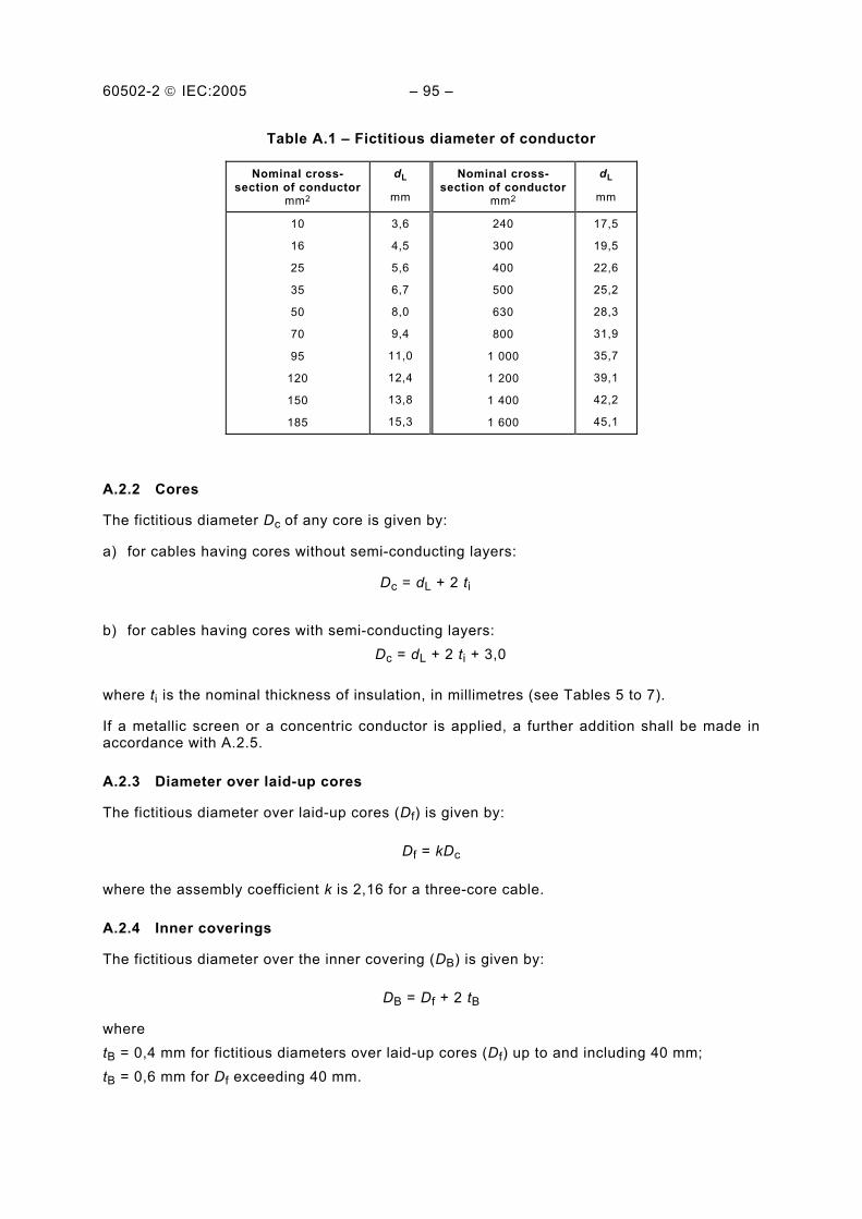
60502-2 IEC:2005 – 95 –
Table A.1 – Fictitious diameter of conductor
Nominal cross-section of conductor
mm2
dL
mm
Nominal cross-section of conductor
mm2
dL
mm
10
16
25
35
50
70
95
120
150
185
3,6
4,5
5,6
6,7
8,0
9,4
11,0
12,4
13,8
15,3
240
300
400
500
630
800
1 000
1 200
1 400
1 600
17,5
19,5
22,6
25,2
28,3
31,9
35,7
39,1
42,2
45,1
A.2.2 Cores
The fictitious diameter Dc of any core is given by:
a) for cables having cores without semi-conducting layers:
Dc = dL + 2 ti
b) for cables having cores with semi-conducting layers: Dc = dL + 2 ti + 3,0
where ti is the nominal thickness of insulation, in millimetres (see Tables 5 to 7).
If a metallic screen or a concentric conductor is applied, a further addition shall be made in accordance with A.2.5.
A.2.3 Diameter over laid-up cores
The fictitious diameter over laid-up cores (Df) is given by:
Df = kDc
where the assembly coefficient k is 2,16 for a three-core cable.
A.2.4 Inner coverings
The fictitious diameter over the inner covering (DB) is given by:
DB = Df + 2 tB
where tB = 0,4 mm for fictitious diameters over laid-up cores (Df) up to and including 40 mm; tB = 0,6 mm for Df exceeding 40 mm.
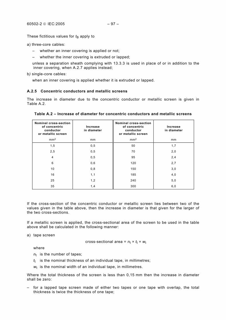
60502-2 IEC:2005 – 97 –
These fictitious values for tB apply to
a) three-core cables: – whether an inner covering is applied or not; – whether the inner covering is extruded or lapped;
unless a separation sheath complying with 13.3.3 is used in place of or in addition to the inner covering, when A.2.7 applies instead;
b) single-core cables: when an inner covering is applied whether it is extruded or lapped.
A.2.5 Concentric conductors and metallic screens
The increase in diameter due to the concentric conductor or metallic screen is given in Table A.2.
Table A.2 – Increase of diameter for concentric conductors and metallic screens
Nominal cross-section of concentric
conductor or metallic screen
Increase in diameter
Nominal cross-section of concentric
conductor or metallic screen
Increase in diameter
mm2 mm mm2 mm
1,5
2,5
4
6
10
16
25
35
0,5
0,5
0,5
0,6
0,8
1,1
1,2
1,4
50
70
95
120
150
185
240
300
1,7
2,0
2,4
2,7
3,0
4,0
5,0
6,0
If the cross-section of the concentric conductor or metallic screen lies between two of the values given in the table above, then the increase in diameter is that given for the larger of the two cross-sections.
If a metallic screen is applied, the cross-sectional area of the screen to be used in the table above shall be calculated in the following manner:
a) tape screen
cross-sectional area = nt × tt × wt where nt is the number of tapes; tt is the nominal thickness of an individual tape, in millimetres; wt is the nominal width of an individual tape, in millimetres.
Where the total thickness of the screen is less than 0,15 mm then the increase in diameter shall be zero:
– for a lapped tape screen made of either two tapes or one tape with overlap, the total thickness is twice the thickness of one tape;

60502-2 IEC:2005 – 99 –
– for a longitudinally applied tape screen: • if the overlap is below 30 %, the total thickness is the thickness of the tape; • if the overlap is greater than or equal to 30 %, the total thickness is twice the
thickness of the tape. b) wire screen (with a counter helix, if any)
cross sectional area- =
4 + w w
2h h h
n dn t w
× ×× ×
π
where nw is the number of wires; dw is the diameter of an individual wire, in millimetres; nh is the number of a counter helix; th is the thickness of a counter helix, in millimetres, if greater than 0,3 mm; wh is the width of a counter helix, in millimetres.
A.2.6 Lead sheath
The fictitious diameter over the lead sheath (Dpb) is given by:
Dpb = Dg + 2 tpb
where Dg is the fictitious diameter under the lead sheath, in millimetres; tpb is the thickness calculated in accordance with 12.1, in millimetres.
A.2.7 Separation sheath
The fictitious diameter over the separation sheath (Ds) is given by:
Ds = Du + 2 ts
where Du is the fictitious diameter under the separation sheath, in millimetres; ts is the thickness calculated in accordance with 13.3.3, in millimetres.
A.2.8 Lapped bedding
The fictitious diameter over the lapped bedding (Dlb) is given by:
Dlb=Dulb + 2 tlb
where Dulb is the fictitious diameter under the lapped bedding, in millimetres; tlb is the thickness of lapped bedding, i.e. 1,5 mm according to 13.3.4.

60502-2 IEC:2005 – 101 –
A.2.9 Additional bedding for tape-armoured cables (provided over the inner covering)
Table A.3 – Increase of diameter for additional bedding
Fictitious diameter under the addition bedding Increase in diameter for additional bedding
Above mm
Up to and including mm mm
–
29
29
–
1,0
1,6
A.2.10 Armour
The fictitious diameter over the armour (Dx) is given for:
a) flat or round wire armour by: Dx = DA + 2 tA + 2 tw
where DA is the diameter under the armour, in millimetres; tA is the thickness or diameter of the armour wire, in millimetres; tw is the thickness of the counter helix, if any, in millimetres, if greater than 0,3 mm.
b) for double-tape armour by:
Dx = DA + 4 tA
where DA is the diameter under the armour, in millimetres; tA is the thickness of the armour tape, in millimetres.

60502-2 IEC:2005 – 103 –
Annex B (informative)
Tabulated continuous current ratings for cables having extruded
insulation and a rated voltage from 3,6/6 kV up to 18/30 kV
B.1 General
This annex deals solely with the steady-state continuous current ratings of single-core and three-core cables having extruded insulation. The tabulated current ratings provided in this annex have been calculated for cables having a rated voltage of 6/10 kV and constructions as detailed in Clause B.2.
These ratings can be applied to cables of similar constructions in the voltage range of 3,6/6 kV to 18/30 kV.
Some parameters such as screen cross-sectional area and oversheath thickness have an influence on the rating of large cables. In addition, the method of screen bonding has to be taken into account in the rating of single-core cables.
The tabulated current ratings have been calculated using the methods set out in IEC 60287.
NOTE 1 For cyclic current ratings, see IEC 60853.
NOTE 2 For short-circuit temperature limits, see IEC 60986.
B.2 Cable constructions
The cable constructions and dimensions for which current ratings have been tabulated are based on those given in this standard. The constructions and dimensions used are not related to specific national designs but reflect different model cables. Armoured three-core cables are assumed to have flat wire armour and single-core cables are assumed to be unarmoured. All the cables have copper tape core screens except the single-core XLPE insulated cable, which has a copper wire screen. The nominal cross-sectional areas of the screens for the model cables is given in Table B.1.
Table B.1 – Nominal screen cross-sectional areas
Nominal area of conductor, mm² 16 25 35 50 70 95 120 150 185 240 300 400
Nominal cross-sectional area of screen, per core, mm²
EPR insulated cable 3 3 4 4 4 5 5 5 6 6 7 8
XLPE insulated cable 16 16 16 16 16 16 16 25 25 25 25 35
The oversheath is taken to be polyethylene for the single core cables and PVC for the three-core cables.
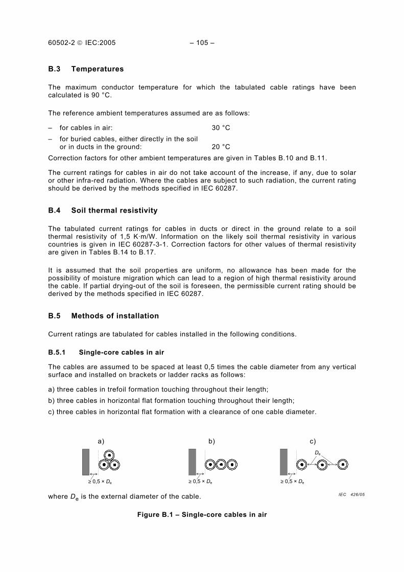
60502-2 IEC:2005 – 105 –
B.3 Temperatures
The maximum conductor temperature for which the tabulated cable ratings have been calculated is 90 °C.
The reference ambient temperatures assumed are as follows:
– for cables in air: 30 °C – for buried cables, either directly in the soil
or in ducts in the ground: 20 °C Correction factors for other ambient temperatures are given in Tables B.10 and B.11.
The current ratings for cables in air do not take account of the increase, if any, due to solar or other infra-red radiation. Where the cables are subject to such radiation, the current rating should be derived by the methods specified in IEC 60287.
B.4 Soil thermal resistivity
The tabulated current ratings for cables in ducts or direct in the ground relate to a soil thermal resistivity of 1,5 K.m/W. Information on the likely soil thermal resistivity in various countries is given in IEC 60287-3-1. Correction factors for other values of thermal resistivity are given in Tables B.14 to B.17.
It is assumed that the soil properties are uniform, no allowance has been made for the possibility of moisture migration which can lead to a region of high thermal resistivity around the cable. If partial drying-out of the soil is foreseen, the permissible current rating should be derived by the methods specified in IEC 60287.
B.5 Methods of installation
Current ratings are tabulated for cables installed in the following conditions.
B.5.1 Single-core cables in air
The cables are assumed to be spaced at least 0,5 times the cable diameter from any vertical surface and installed on brackets or ladder racks as follows:
a) three cables in trefoil formation touching throughout their length; b) three cables in horizontal flat formation touching throughout their length; c) three cables in horizontal flat formation with a clearance of one cable diameter.
a)
≥ 0,5 × De
b)
≥ 0,5 × De
c)
≥ 0,5 × De
De
where De is the external diameter of the cable.
Figure B.1 – Single-core cables in air
IEC 426/05

60502-2 IEC:2005 – 107 –
B.5.2 Single-core cables buried direct
Current ratings are given for cables buried direct in the ground at a depth of 0,8 m under the following conditions:
a) three cables in trefoil formation touching throughout their length; b) three cables in horizontal flat formation with a clearance of one cable diameter, De.
a)
b)
De De
Figure B.2 – Single-core cables buried direct
The cable depth is measured to the cable axis or centre of the trefoil group.
B.5.3 Single-core cables in earthenware ducts
Current ratings are given for cables in earthenware ducts buried at a depth of 0,8 m with one cable per duct as follows:
a) three cables in trefoil ducts touching throughout their length; b) three cables in horizontal flat formation, ducts touching throughout their length.
a)
b)
Figure B.3 – Single-core cables in earthenware ducts
The ducts are assumed to be earthenware having an inside diameter of 1,5 times the outside diameter of the cable and a wall thickness equal to 6 % of the duct inside diameter. The ratings are based on the assumption that the ducts are air filled. If the ducts have been filled with a material such as Bentonite, then it is usual to adopt the current ratings for cables buried direct.
The tabulated ratings may be applied to cables in ducts having an inside diameter of between 1,2 and 2 times the outside diameter of the cables. For this range of diameters the variation in the rating is less than 2 % of the tabulated value.
IEC 427/05
IEC 428/05

60502-2 IEC:2005 – 109 –
B.5.4 Three-core cables
Current ratings are given for three-core cables installed under the following conditions:
a) single cable in air spaced at least 0,3 times the cable diameter from any vertical surface; b) single cable buried direct in the ground at a depth of 0,8 m; c) single cable in a buried earthenware duct having dimensions calculated in the same
manner as for the single-core cables in ducts. The depth of burial of the duct is 0,8 m. a)
≥ 0,3 × De
b)
c)
Figure B.4 – Three-core cables
B.6 Screen bonding
All the tabulated ratings for single-core cables assume that the cable screens are solidly bonded, i.e. bonded at both ends of the cables.
B.7 Cable loading
The tabulated ratings relate to circuits carrying a balanced three-phase load at a rated frequency of 50 Hz.
B.8 Rating factors for grouped circuits
The tabulated current ratings apply to a set of three single-core cables or one three-core cable forming a three-phase circuit. When a number of circuits are installed in close proximity the rating should be reduced by the appropriate factor from Tables B.18 to B.23.
These rating factors should also be applied to groups of parallel cables forming the same circuit. In such cases, attention should also be given to the arrangement of the cables to ensure that the load current is shared equally between the parallel cables.
B.9 Correction factors
The correction factors given in Tables B.10 to B.23 for temperature, installation conditions and grouping are averages over a range of conductor sizes and cable types. For particular cases, the correction factor may be calculated using the methods in IEC 60287-2-1.
IEC 429/05
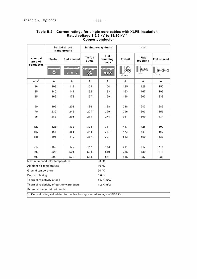
60502-2 IEC:2005 – 111 –
Table B.2 – Current ratings for single-core cables with XLPE insulation – Rated voltage 3,6/6 kV to 18/30 kV * –
Copper conductor
Buried direct in the ground
In single-way ducts In air
Trefoil Flat spaced Trefoil ducts
Flat touching
ducts Trefoil Flat
touching Flat spacedNominal area of
conductor
≥ 0,5 × De
≥ 0,5 × De
≥ 0,5 × De
De
mm2 A A A A A A A
16 109 113 103 104 125 128 150
25 140 144 132 133 163 167 196
35 166 172 157 159 198 203 238
50 196 203 186 188 238 243 286
70 239 246 227 229 296 303 356
95 285 293 271 274 361 369 434
120 323 332 308 311 417 426 500
150 361 366 343 347 473 481 559
185 406 410 387 391 543 550 637
240 469 470 447 453 641 647 745
300 526 524 504 510 735 739 846
400 590 572 564 571 845 837 938 Maximum conductor temperature 90 °C
Ambient air temperature 30 °C
Ground temperature 20 °C
Depth of laying 0,8 m
Thermal resistivity of soil 1,5 K.m/W
Thermal resistivity of earthenware ducts 1,2 K.m/W
Screens bonded at both ends.
* Current rating calculated for cables having a rated voltage of 6/10 kV.
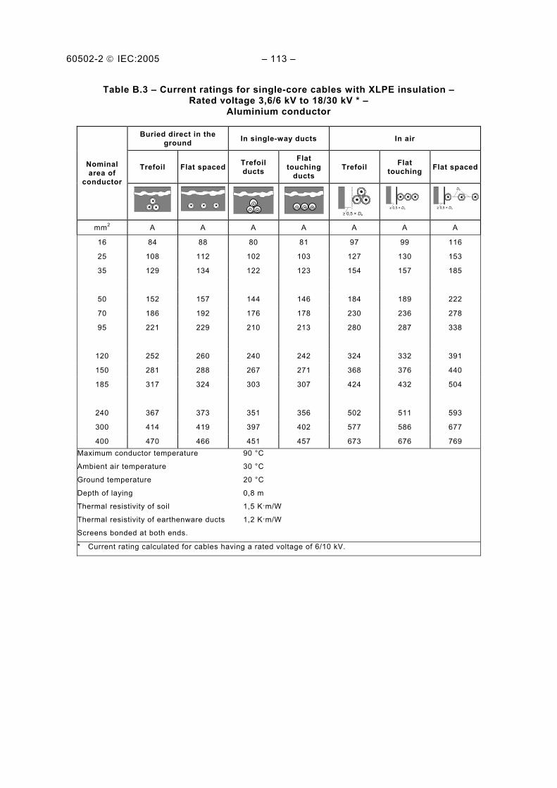
60502-2 IEC:2005 – 113 –
Table B.3 – Current ratings for single-core cables with XLPE insulation – Rated voltage 3,6/6 kV to 18/30 kV * –
Aluminium conductor
Buried direct in the ground In single-way ducts In air
Trefoil Flat spaced Trefoil ducts
Flat touching
ducts Trefoil Flat
touching Flat spacedNominal area of
conductor
≥ 0,5 × De
≥ 0,5 × De
≥ 0,5 × De
De
mm2 A A A A A A A
16 84 88 80 81 97 99 116
25 108 112 102 103 127 130 153
35 129 134 122 123 154 157 185
50 152 157 144 146 184 189 222
70 186 192 176 178 230 236 278
95 221 229 210 213 280 287 338
120 252 260 240 242 324 332 391
150 281 288 267 271 368 376 440
185 317 324 303 307 424 432 504
240 367 373 351 356 502 511 593
300 414 419 397 402 577 586 677
400 470 466 451 457 673 676 769 Maximum conductor temperature 90 °C
Ambient air temperature 30 °C
Ground temperature 20 °C
Depth of laying 0,8 m
Thermal resistivity of soil 1,5 K.m/W
Thermal resistivity of earthenware ducts 1,2 K.m/W
Screens bonded at both ends.
* Current rating calculated for cables having a rated voltage of 6/10 kV.

60502-2 IEC:2005 – 115 –
Table B.4 – Current ratings for single-core cables with EPR insulation – Rated voltage 3,6/6 kV to 18/30 kV * –
Copper conductor
Buried direct in the ground In single-way ducts In air
Trefoil Flat spaced Trefoil ducts
Flat touching
ducts Trefoil Flat
touching Flat spacedNominal area of
conductor
≥ 0,5 × De
≥ 0,5 × De
≥ 0,5 × De
De
mm2 A A A A A A A
16 106 109 99 100 116 119 138
25 136 140 128 129 153 156 181
35 162 167 153 154 186 190 221
50 192 198 181 183 224 229 266
70 234 242 222 224 280 287 334
95 280 289 266 269 343 352 409
120 319 329 303 306 398 407 474
150 357 369 341 344 454 465 540
185 403 417 386 390 522 534 621
240 467 484 449 454 619 634 736
300 526 545 509 515 712 728 843
400 597 618 580 588 825 843 977 Maximum conductor temperature 90 °C
Ambient air temperature 30 °C
Ground temperature 20 °C
Depth of laying 0,8 m
Thermal resistivity of soil 1,5 K.m/W
Thermal resistivity of earthenware ducts 1,2 K.m/W
Screens bonded at both ends.
* Current rating calculated for cables having a rated voltage of 6/10 kV.

60502-2 IEC:2005 – 117 –
Table B.5 – Current ratings for single-core cables with EPR insulation – Rated voltage 3,6/6 kV to 18/30 kV * –
Aluminium conductor
Buried direct in the ground In single-way ducts In air
Trefoil Flat spaced Trefoil ducts
Flat touching
ducts Trefoil Flat
touching Flat spacedNominal area of
conductor
≥ 0,5 × De
≥ 0,5 × De
≥ 0,5 × De
De
mm2 A A A A A A A
16 82 84 77 78 90 92 107
25 105 109 99 100 119 121 141
35 126 130 118 120 144 147 171
50 149 153 140 142 174 178 207
70 182 188 172 174 218 223 259
95 217 224 206 208 266 273 317
120 247 256 235 238 309 317 368
150 277 287 264 267 352 361 419
185 314 325 300 303 406 417 484
240 364 377 350 354 483 495 575
300 411 426 397 401 556 570 659
400 471 487 456 462 651 667 770
Maximum conductor temperature 90 °C
Ambient air temperature 30 °C
Ground temperature 20 °C
Depth of laying 0,8 m
Thermal resistivity of soil 1,5 K.m/W
Thermal resistivity of earthenware ducts 1,2 K.m/W
Screens bonded at both ends.
* Current rating calculated for cables having a rated voltage of 6/10 kV.

60502-2 IEC:2005 – 119 –
Table B.6 – Current rating for three-core XLPE insulated cables – Rated voltage 3,6/6 kV to 18/30 kV * –
Copper conductor, armoured and unarmoured
Unarmoured Armoured
Buried direct in ground
In a buried duct In air Buried direct
in ground In a buried
duct In air
Nominal area of conductor
≥ 0,3 × De
≥ 0,3 × De
mm2 A A A A A A
16 101 87 109 101 88 110
25 129 112 142 129 112 143
35 153 133 170 154 134 172
50 181 158 204 181 158 205
70 221 193 253 220 194 253
95 262 231 304 263 232 307
120 298 264 351 298 264 352
150 334 297 398 332 296 397
185 377 336 455 374 335 453
240 434 390 531 431 387 529
300 489 441 606 482 435 599
400 553 501 696 541 492 683 Maximum conductor temperature 90 °C
Ambient air temperature 30 °C
Ground temperature 20 °C
Depth of laying 0,8 m
Thermal resistivity of soil 1,5 K.m/W
Thermal resistivity of earthenware ducts 1,2 K.m/W
* Current rating calculated for cables having a rated voltage of 6/10 kV.

60502-2 IEC:2005 – 121 –
Table B.7 – Current rating for three-core XLPE insulated cables – Rated voltage 3,6/6 kV to 18/30 kV * –
Aluminium conductor, armoured and unarmoured
Unarmoured Armoured
Buried direct in ground
In a buried duct In air Buried direct
in ground In a buried
duct In air
Nominal area of conductor
≥ 0,3 × De
≥ 0,3 × De
mm2 A A A A A A
16 78 67 84 78 68 85
25 100 87 110 100 87 111
35 119 103 132 119 104 133
50 140 122 158 140 123 159
70 171 150 196 171 150 196
95 203 179 236 204 180 238
120 232 205 273 232 206 274
150 260 231 309 259 231 309
185 294 262 355 293 262 354
240 340 305 415 338 304 415
300 384 346 475 380 343 472
400 438 398 552 432 393 545 Maximum conductor temperature 90 °C
Ambient air temperature 30 °C
Ground temperature 20 °C
Depth of laying 0,8 m
Thermal resistivity of soil 1,5 K.m/W
Thermal resistivity of earthenware ducts 1,2 K.m/W
* Current rating calculated for cables having a rated voltage of 6/10 kV.
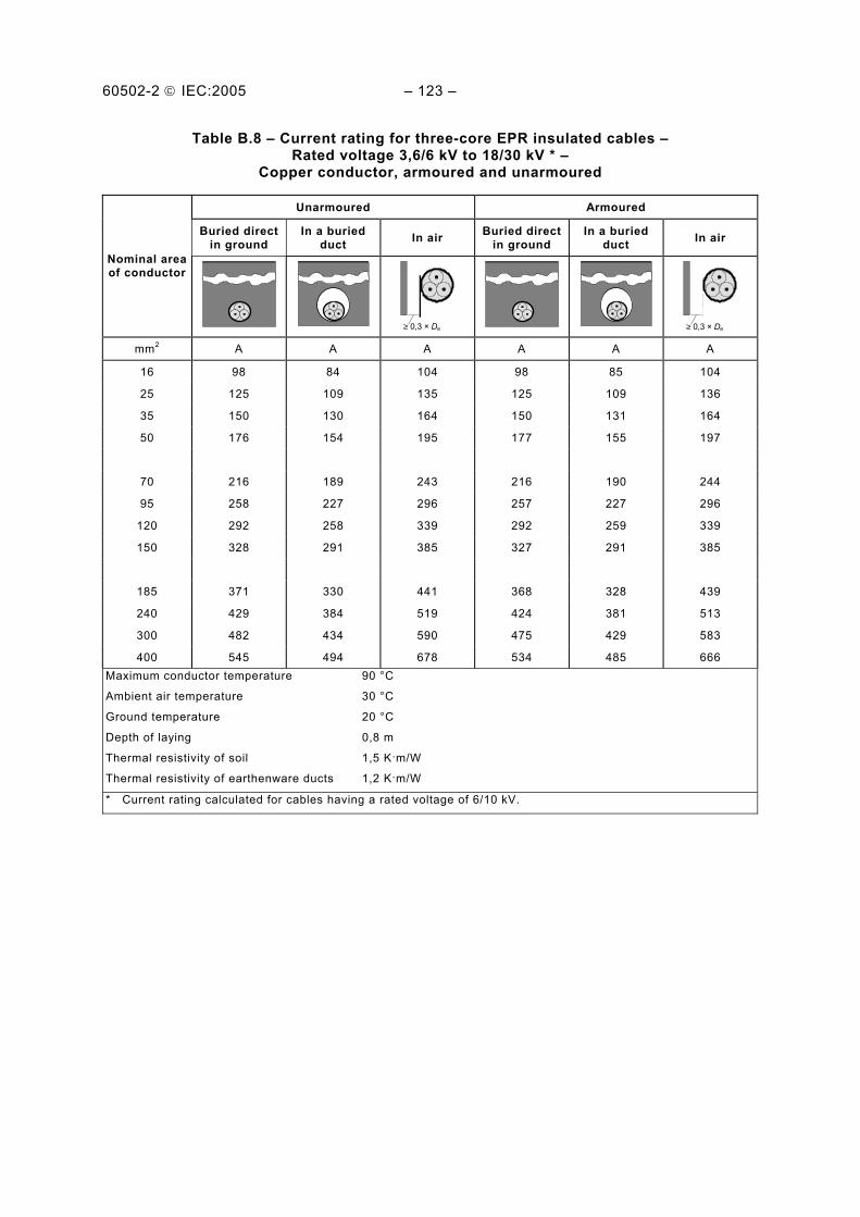
60502-2 IEC:2005 – 123 –
Table B.8 – Current rating for three-core EPR insulated cables – Rated voltage 3,6/6 kV to 18/30 kV * –
Copper conductor, armoured and unarmoured
Unarmoured Armoured
Buried direct in ground
In a buried duct In air Buried direct
in ground In a buried
duct In air
Nominal area of conductor
≥ 0,3 × De
≥ 0,3 × De
mm2 A A A A A A
16 98 84 104 98 85 104
25 125 109 135 125 109 136
35 150 130 164 150 131 164
50 176 154 195 177 155 197
70 216 189 243 216 190 244
95 258 227 296 257 227 296
120 292 258 339 292 259 339
150 328 291 385 327 291 385
185 371 330 441 368 328 439
240 429 384 519 424 381 513
300 482 434 590 475 429 583
400 545 494 678 534 485 666 Maximum conductor temperature 90 °C
Ambient air temperature 30 °C
Ground temperature 20 °C
Depth of laying 0,8 m
Thermal resistivity of soil 1,5 K.m/W
Thermal resistivity of earthenware ducts 1,2 K.m/W
* Current rating calculated for cables having a rated voltage of 6/10 kV.

60502-2 IEC:2005 – 125 –
Table B.9 – Current rating for three-core EPR insulated cables – Rated voltage 3,6/6 kV to 18/30 kV * –
Aluminium conductor, armoured and unarmoured
Unarmoured Armoured
Buried direct in ground
In a buried duct In air Buried direct
in ground In a buried
duct In air
Nominal area of conductor
≥ 0,3 × De
≥ 0,3 × De
mm2 A A A A A A
16 76 65 80 76 66 81
25 97 84 105 97 85 105
35 116 101 127 116 101 127
50 137 119 151 137 120 153
70 167 147 189 168 147 190
95 200 176 229 200 176 230
120 227 201 263 227 201 264
150 255 226 299 254 226 300
185 289 257 343 288 257 343
240 335 300 406 332 299 402
300 378 340 462 374 338 459
400 432 392 538 426 387 530 Température maximale de l’âme 90 °C
Température ambiante 30 °C
Température du sol 20 °C
Profondeur de pose 0,8 m
Résistivité thermique du sol 1,5 K.m/W
Résistivité thermique du conduit en terre cuite 1,2 K.m/W
* Current rating calculated for cables having a rated voltage of 6/10 kV.

60502-2 IEC:2005 – 127 –
Table B.10 – Correction factors for ambient air temperatures other than 30 °C
Ambient air temperature °C
Maximum conductor temperature
°C 20 25 35 40 45 50 55 60
90 1,08 1,04 0,96 0,91 0,87 0,82 0,76 0,71
Table B.11 – Correction factors for ambient ground temperatures other than 20 °C
Ambient ground temperature °C
Maximum conductor temperature
°C 10 15 25 30 35 40 45 50
90 1,07 1,04 0,96 0,93 0,89 0,85 0,80 0,76
Table B.12 – Correction factors for depths of laying other than 0,8 m for direct buried cables
Single-core cables
Nominal conductor size mm2
Depth of laying m
≤185 mm2 >185 mm2
Three-core cables
0,5 1,04 1,06 1,04
0,6 1,02 1,04 1,03
1 0,98 0,97 0,98
1,25 0,96 0,95 0,96
1,5 0,95 0,93 0,95
1,75 0,94 0,91 0,94
2 0,93 0,90 0,93
2,5 0,91 0,88 0,91
3 0,90 0,86 0,90
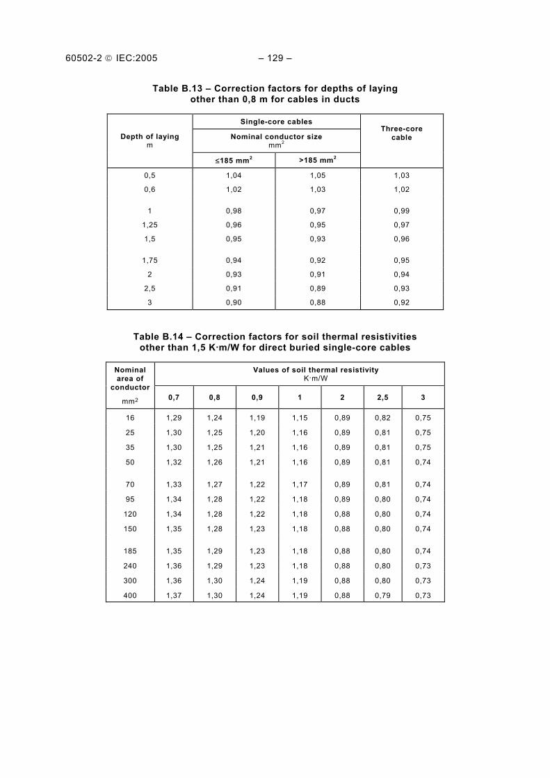
60502-2 IEC:2005 – 129 –
Table B.13 – Correction factors for depths of laying other than 0,8 m for cables in ducts
Single-core cables
Nominal conductor size mm2
Three-core cable Depth of laying
m
≤185 mm2 >185 mm2
0,5 1,04 1,05 1,03
0,6 1,02 1,03 1,02
1 0,98 0,97 0,99
1,25 0,96 0,95 0,97
1,5 0,95 0,93 0,96
1,75 0,94 0,92 0,95
2 0,93 0,91 0,94
2,5 0,91 0,89 0,93
3 0,90 0,88 0,92
Table B.14 – Correction factors for soil thermal resistivities other than 1,5 K.m/W for direct buried single-core cables
Values of soil thermal resistivity K.m/W
Nominal area of
conductor
mm2 0,7 0,8 0,9 1 2 2,5 3
16 1,29 1,24 1,19 1,15 0,89 0,82 0,75
25 1,30 1,25 1,20 1,16 0,89 0,81 0,75
35 1,30 1,25 1,21 1,16 0,89 0,81 0,75
50 1,32 1,26 1,21 1,16 0,89 0,81 0,74
70 1,33 1,27 1,22 1,17 0,89 0,81 0,74
95 1,34 1,28 1,22 1,18 0,89 0,80 0,74
120 1,34 1,28 1,22 1,18 0,88 0,80 0,74
150 1,35 1,28 1,23 1,18 0,88 0,80 0,74
185 1,35 1,29 1,23 1,18 0,88 0,80 0,74
240 1,36 1,29 1,23 1,18 0,88 0,80 0,73
300 1,36 1,30 1,24 1,19 0,88 0,80 0,73
400 1,37 1,30 1,24 1,19 0,88 0,79 0,73

60502-2 IEC:2005 – 131 –
Table B.15 – Correction factors for soil thermal resistivities other than 1,5 K.m/W single-core cables in buried ducts
Values of soil thermal resistivity K.m/W
Nominal area of
conductor
mm2 0,7 0,8 0,9 1 2 2,5 3
16 1,20 1,17 1,14 1,11 0,92 0,85 0,79
25 1,21 1,17 1,14 1,12 0,91 0,85 0,79
35 1,21 1,18 1,15 1,12 0,91 0,84 0,79
50 1,21 1,18 1,15 1,12 0,91 0,84 0,78
70 1,22 1,19 1,15 1,12 0,91 0,84 0,78
95 1,23 1,19 1,16 1,13 0,91 0,84 0,78
120 1,23 1,20 1,16 1,13 0,91 0,84 0,78
150 1,24 1,20 1,16 1,13 0,91 0,83 0,78
185 1,24 1,20 1,17 1,13 0,91 0,83 0,78
240 1,25 1,21 1,17 1,14 0,90 0,83 0,77
300 1,25 1,21 1,17 1,14 0,90 0,83 0,77
400 1,25 1,21 1,17 1,14 0,90 0,83 0,77
Table B.16 – Correction factors for soil thermal resistivities other than 1,5 K.m/W for direct buried three-core cables
Values of soil thermal resistivity K•m/W
Nominal area of conductor
mm2 0,7 0,8 0,9 1 2 2,5 3
16 1,23 1,19 1,16 1,13 0,91 0,84 0,78
25 1,24 1,20 1,16 1,13 0,91 0,84 0,78
35 1,25 1,21 1,17 1,13 0,91 0,83 0,78
50 1,25 1,21 1,17 1,14 0,91 0,83 0,77
70 1,26 1,21 1,18 1,14 0,90 0,83 0,77
95 1,26 1,22 1,18 1,14 0,90 0,83 0,77
120 1,26 1,22 1,18 1,14 0,90 0,83 0,77
150 1,27 1,22 1,18 1,15 0,90 0,83 0,77
185 1,27 1,23 1,18 1,15 0,90 0,83 0,77
240 1,28 1,23 1,19 1,15 0,90 0,83 0,77
300 1,28 1,23 1,19 1,15 0,90 0,82 0,77
400 1,28 1,23 1,19 1,15 0,90 0,82 0,76

60502-2 IEC:2005 – 133 –
Table B.17 – Correction factors for soil thermal resistivities other than 1,5 K•m/W for three-core cables in ducts
Nominal area of
conductor
Values of soil thermal resistivity K•m/W
mm2 0,7 0,8 0,9 1 2 2,5 3
16 1,12 1,11 1,09 1,08 0,94 0,89 0,84
25 1,14 1,12 1,10 1,08 0,94 0,89 0,84
35 1,14 1,12 1,10 1,08 0,94 0,88 0,84
50 1,14 1,12 1,10 1,08 0,94 0,88 0,84
70 1,15 1,13 1,11 1,09 0,94 0,88 0,83
95 1,15 1,13 1,11 1,09 0,94 0,88 0,83
120 1,15 1,13 1,11 1,09 0,93 0,88 0,83
150 1,16 1,13 1,11 1,09 0,93 0,88 0,83
185 1,16 1,14 1,11 1,09 0,93 0,87 0,83
240 1,16 1,14 1,12 1,10 0,93 0,87 0,82
300 1,17 1,14 1,12 1,10 0,93 0,87 0,82
400 1,17 1,14 1,12 1,10 0,92 0,86 0,81
Table B.18 – Correction factors for groups of three-core cables in horizontal formation laid direct in the ground
Spacing between cable centres mm
Number of cables in
group Touching 200 400 600 800
2 0,80 0,86 0,90 0,92 0,94
3 0,69 0,77 0,82 0,86 0,89
4 0,62 0,72 0,79 0,83 0,87
5 0,57 0,68 0,76 0,81 0,85
6 0,54 0,65 0,74 0,80 0,84
7 0,51 0,63 0,72 0,78 0,83
8 0,49 0,61 0,71 0,78
9 0,47 0,60 0,70 0,77 -
10 0,46 0,59 0,69 - -
11 0,45 0,57 0,69 - -
12 0,43 0,56 0,68 - -

60502-2 IEC:2005 – 135 –
Table B.19 – Correction factors for groups of three-phase circuits of single-core cables laid direct in the ground
Spacing between group centres mm
Number of cables in
group Touching 200 400 600 800
2 0,73 0,83 0,88 0,90 0,92
3 0,60 0,73 0,79 0,83 0,86
4 0,54 0,68 0,75 0,80 0,84
5 0,49 0,63 0,72 0,78 0,82
6 0,46 0,61 0,70 0,76 0,81
7 0,43 0,58 0,68 0,75 0,80
8 0,41 0,57 0,67 0,74 -
9 0,39 0,55 0,66 0,73 -
10 0,37 0,54 0,65 - -
11 0,36 0,53 0,64 - -
12 0,35 0,52 0,64 - -
Table B.20 – Correction factors for groups of three-core cables in single way ducts in horizontal formation
Spacing between duct centres mm
Number of cables in
group Touching 200 400 600 800
2 0,85 0,88 0,92 0,94 0,95
3 0,75 0,80 0,85 0,88 0,91
4 0,69 0,75 0,82 0,86 0,89
5 0,65 0,72 0,79 0,84 0,87
6 0,62 0,69 0,77 0,83 0,87
7 0,59 0,67 0,76 0,82 0,86
8 0,57 0,65 0,75 0,81 -
9 0,55 0,64 0,74 0,80 -
10 0,54 0,63 0,73 - -
11 0,52 0,62 0,73 - -
12 0,51 0,61 0,72 - -
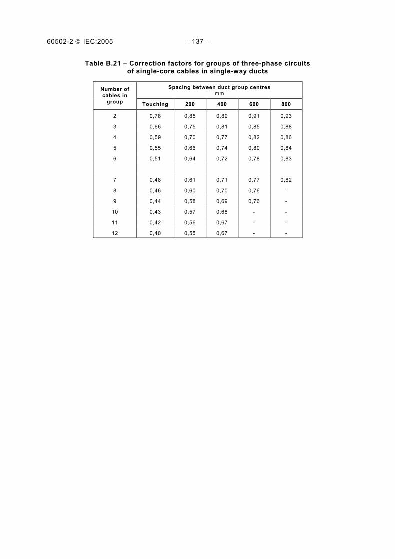
60502-2 IEC:2005 – 137 –
Table B.21 – Correction factors for groups of three-phase circuits of single-core cables in single-way ducts
Spacing between duct group centres mm
Number of cables in
group Touching 200 400 600 800
2 0,78 0,85 0,89 0,91 0,93
3 0,66 0,75 0,81 0,85 0,88
4 0,59 0,70 0,77 0,82 0,86
5 0,55 0,66 0,74 0,80 0,84
6 0,51 0,64 0,72 0,78 0,83
7 0,48 0,61 0,71 0,77 0,82
8 0,46 0,60 0,70 0,76 -
9 0,44 0,58 0,69 0,76 -
10 0,43 0,57 0,68 - -
11 0,42 0,56 0,67 - -
12 0,40 0,55 0,67 - -

60502-2 IEC:2005 – 139 –
Table B.22 – Reduction factors for groups of more than one multi-core cable in air – To be applied to the current-carrying capacity for one multi-core cable in free air
Number of cables Method of installation Number
of trays 1 2 3 4 6 9
Touching
≥ 20 mm
1
2
3
1,00
1,00
1,00
0,88
0,87
0,86
0,82
0,80
0,79
0,79
0,77
0,76
0,76
0,73
0,71
0,73
0,68
0,66 Cables on perforated trays Spaced
≥ 20 mm
De
1
2
3
1,00
1,00
1,00
1,00
0,99
0,98
0,98
0,96
0,95
0,95
0,92
0,91
0,91
0,87
0,85
-
-
-
≥ 225 mm
Touching
1
2
1,00
1,00
0,88
0,88
0,82
0,81
0,78
0,76
0,73
0,71
0,72
0,70
Cables on vertical perforated trays
≥
225 mm
De
Spaced
1
2
1,00
1,00
0,91
0,91
0,89
0,88
0,88
0,87
0,87
0,85
-
-
Touching
≥ 20 mm
1
2
3
1,00
1,00
1,00
0,87
0,86
0,85
0,82
0,80
0,79
0,80
0,78
0,76
0,79
0,76
0,73
0,78
0,73
0,70 Cables on ladder supports, cleats,
etc. Spaced
≥ 20 mm
De
1
2
3
1,00
1,00
1,00
1,00
0,99
0,98
1,00
0,98
0,97
1,00
0,97
0,96
1,00
0,96
0,93
-
-
-
NOTE 1 Values given are averages for the cable types and range of conductor sizes considered. The spread of values is generally less than 5 %.
NOTE 2 Factors apply to single layer groups of cables as shown above and do not apply when cables are installed in more than one layer touching each other. Values for such installations may be significantly lower and must be determined by an appropriate method.
NOTE 3 Values are given for vertical spacings between trays of 300 mm and at least 20 mm between trays and wall. For closer spacing, the factors should be reduced.
NOTE 4 Values are given for horizontal spacing between trays of 225 mm with trays mounted back to back. For closer spacing, the factors should be reduced.
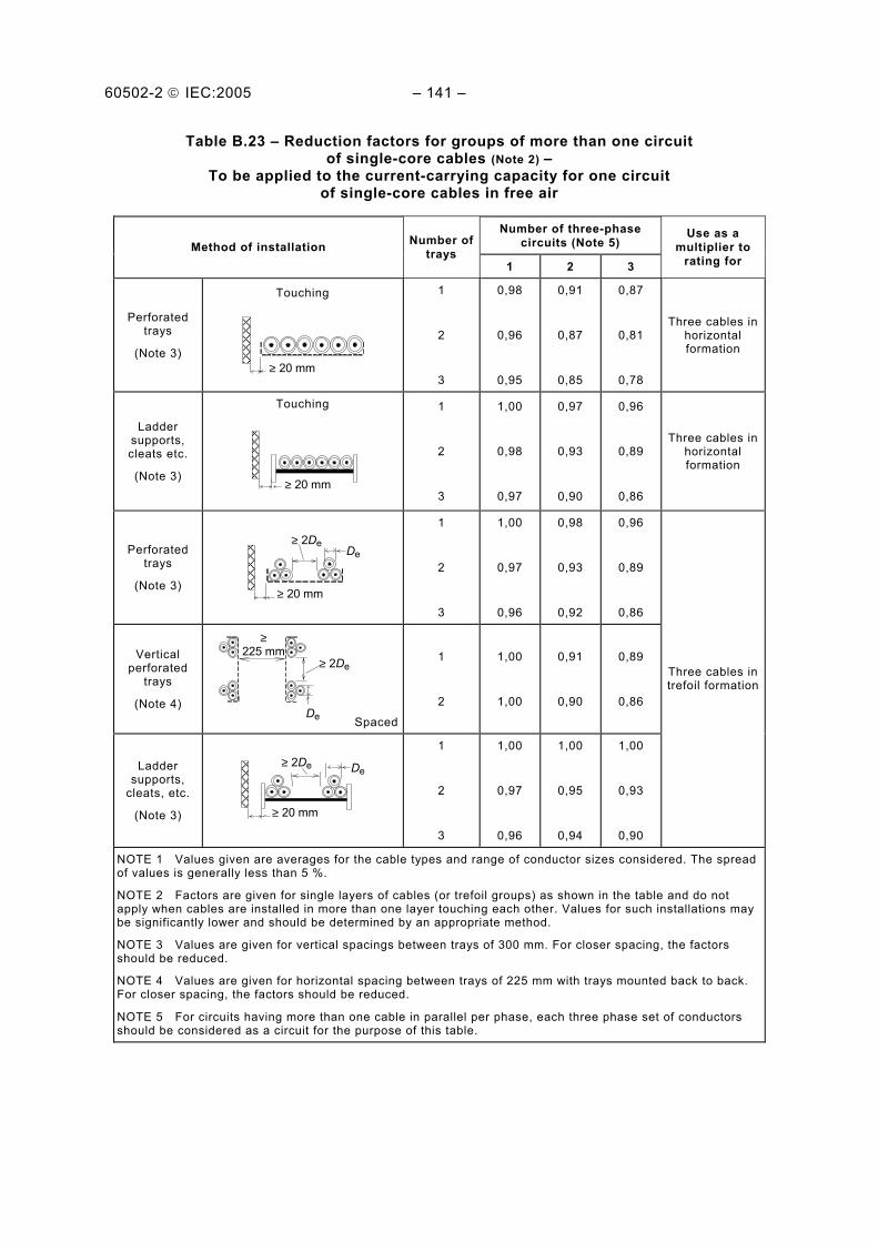
60502-2 IEC:2005 – 141 –
Table B.23 – Reduction factors for groups of more than one circuit of single-core cables (Note 2) –
To be applied to the current-carrying capacity for one circuit of single-core cables in free air
Number of three-phase circuits (Note 5) Method of installation Number of
trays 1 2 3
Use as a multiplier to
rating for
Perforated trays
(Note 3)
Touching
≥ 20 mm
1
2
3
0,98
0,96
0,95
0,91
0,87
0,85
0,87
0,81
0,78
Three cables in horizontal formation
Ladder supports, cleats etc.
(Note 3)
Touching
≥ 20 mm
1
2
3
1,00
0,98
0,97
0,97
0,93
0,90
0,96
0,89
0,86
Three cables in horizontal formation
Perforated trays
(Note 3)
≥ 20 mm
≥ 2De De
1
2
3
1,00
0,97
0,96
0,98
0,93
0,92
0,96
0,89
0,86
Vertical perforated
trays
(Note 4)
De
≥ 2De ≥
225 mm
Spaced
1
2
1,00
1,00
0,91
0,90
0,89
0,86
Ladder supports,
cleats, etc.
(Note 3)
≥ 20 mm
≥ 2De De
1
2
3
1,00
0,97
0,96
1,00
0,95
0,94
1,00
0,93
0,90
Three cables in trefoil formation
NOTE 1 Values given are averages for the cable types and range of conductor sizes considered. The spread of values is generally less than 5 %.
NOTE 2 Factors are given for single layers of cables (or trefoil groups) as shown in the table and do not apply when cables are installed in more than one layer touching each other. Values for such installations may be significantly lower and should be determined by an appropriate method.
NOTE 3 Values are given for vertical spacings between trays of 300 mm. For closer spacing, the factors should be reduced.
NOTE 4 Values are given for horizontal spacing between trays of 225 mm with trays mounted back to back. For closer spacing, the factors should be reduced.
NOTE 5 For circuits having more than one cable in parallel per phase, each three phase set of conductors should be considered as a circuit for the purpose of this table.

60502-2 IEC:2005 – 143 –
Annex C (normative)
Rounding of numbers
C.1 Rounding of numbers for the purpose of the fictitious calculation method
The following rules apply when rounding numbers in calculating fictitious diameters and determining dimensions of component layers in accordance with Annex A.
When the calculated value at any stage has more than one decimal place, the value shall be rounded to one decimal place, i.e. to the nearest 0,1 mm. The fictitious diameter at each stage shall be rounded to 0,1 mm and, when used to determine the thickness or dimension of an overlying layer, it shall be rounded before being used in the appropriate formula or table. The thickness calculated from the rounded value of the fictitious diameter shall, in turn, be rounded to 0,1 mm as required in Annex A.
To illustrate these rules, the following practical examples are given:
a) when the figure in the second decimal place before rounding is 0, 1, 2, 3 or 4, then the figure retained in the first decimal place remains unchanged (rounding down); Examples:
2,12 ≈ 2,1 2,449 ≈ 2,4 25,0478 ≈ 25,0
b) when the figure in the second decimal place before rounding is 9, 8, 7, 6 or 5, then the figure in the first decimal place is increased by one (rounding up). Examples:
2,17 ≈ 2,2 2,453 ≈ 2,5 30,050 ≈ 30,1
C.2 Rounding of numbers for other purposes
For purposes other than those considered under C.1, it may be required that values are rounded to more than one decimal place. This may occur, for instance, in calculating the average value of several measurement results, or the minimum value by applying a percentage tolerance to a given nominal value. In these cases, rounding shall be carried out to the number of decimal places specified in the relevant clauses.
The method of rounding shall then be as follows:
a) if the last figure to be retained is followed, before rounding, by 0, 1, 2, 3 or 4, it shall remain unchanged (rounding down);
b) if the last figure to be retained is followed, before rounding, by 9, 8, 7, 6 or 5, it shall be increased by one (rounding up). Examples:
2,449 ≈ 2,45 rounded to two decimal places 2,449 ≈ 2,4 rounded to one decimal place 25,0478 ≈ 25,048 rounded to three decimal places 25,0478 ≈ 25,05 rounded to two decimal places 25,0478 ≈ 25,0 rounded to one decimal place
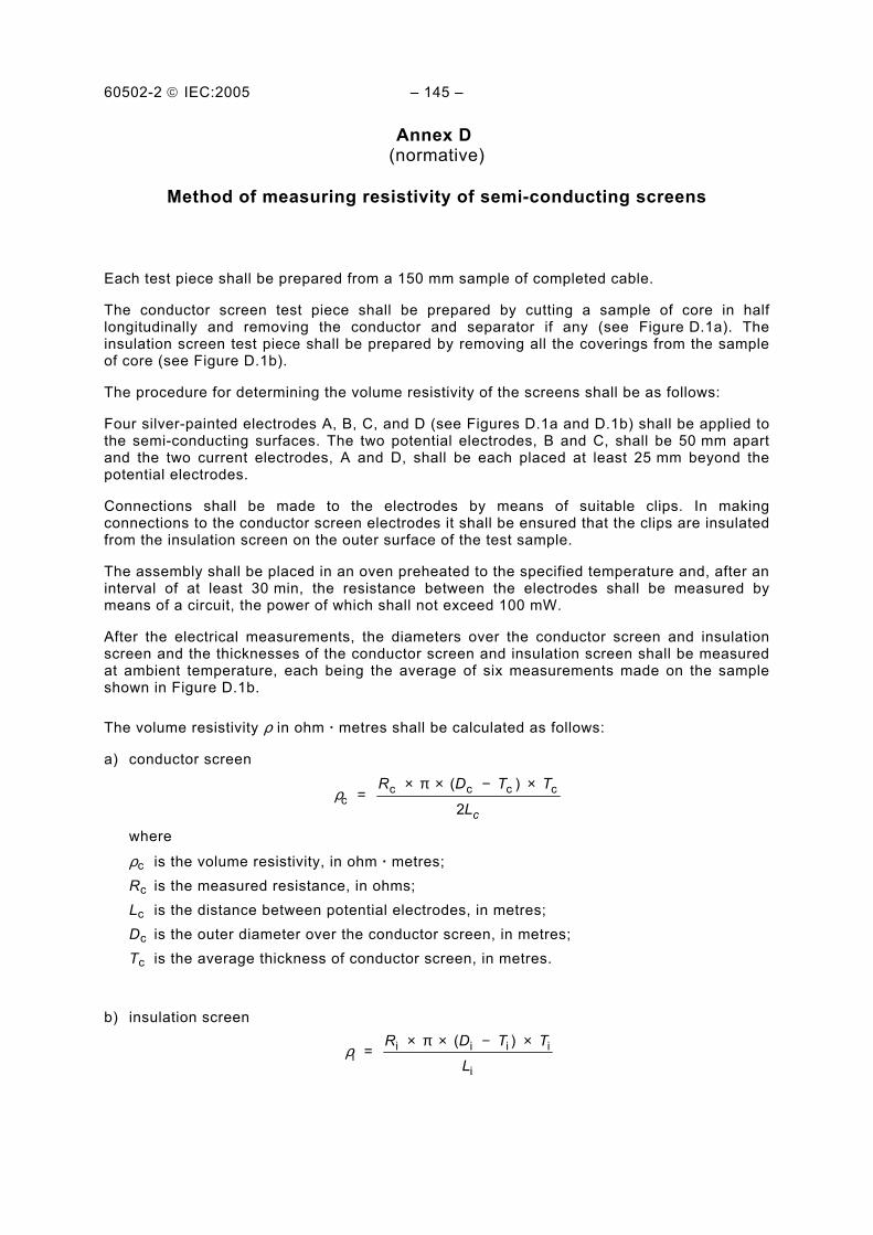
60502-2 IEC:2005 – 145 –
Annex D (normative)
Method of measuring resistivity of semi-conducting screens
Each test piece shall be prepared from a 150 mm sample of completed cable.
The conductor screen test piece shall be prepared by cutting a sample of core in half longitudinally and removing the conductor and separator if any (see Figure D.1a). The insulation screen test piece shall be prepared by removing all the coverings from the sample of core (see Figure D.1b).
The procedure for determining the volume resistivity of the screens shall be as follows:
Four silver-painted electrodes A, B, C, and D (see Figures D.1a and D.1b) shall be applied to the semi-conducting surfaces. The two potential electrodes, B and C, shall be 50 mm apart and the two current electrodes, A and D, shall be each placed at least 25 mm beyond the potential electrodes.
Connections shall be made to the electrodes by means of suitable clips. In making connections to the conductor screen electrodes it shall be ensured that the clips are insulated from the insulation screen on the outer surface of the test sample.
The assembly shall be placed in an oven preheated to the specified temperature and, after an interval of at least 30 min, the resistance between the electrodes shall be measured by means of a circuit, the power of which shall not exceed 100 mW.
After the electrical measurements, the diameters over the conductor screen and insulation screen and the thicknesses of the conductor screen and insulation screen shall be measured at ambient temperature, each being the average of six measurements made on the sample shown in Figure D.1b.
The volume resistivity ρ in ohm · metres shall be calculated as follows:
a) conductor screen
ρc = ( ) c c c cR D T T
Lc
× × − ×π
2
where
ρc is the volume resistivity, in ohm · metres; Rc is the measured resistance, in ohms; Lc is the distance between potential electrodes, in metres; Dc is the outer diameter over the conductor screen, in metres; Tc is the average thickness of conductor screen, in metres.
b) insulation screen
ρii
= ( ) i i i iR D T T
L
× × − ×π
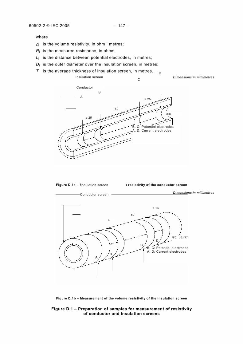
60502-2 IEC:2005 – 147 –
where
ρi is the volume resistivity, in ohm · metres; Ri is the measured resistance, in ohms; Li is the distance between potential electrodes, in metres; Di is the outer diameter over the insulation screen, in metres; Ti is the average thickness of insulation screen, in metres.
Dimensions in millimetres
Figure D.1a – Measurement of the volume resistivity of the conductor screen
Dimensions in millimetres
Figure D.1b – Measurement of the volume resistivity of the insulation screen
Figure D.1 – Preparation of samples for measurement of resistivity of conductor and insulation screens
B, C: Potential electrodes A, D: Current electrodes
B
50
≥ 25
≥ 25
D
C
A
Insulation screen
Conductor
IEC 252/97
Insulation screen
B, C: Potential electrodes A, D: Current electrodes
DC
BA
≥ 25
50
≥
Conductor screen
IEC 253/97
60502-2 IEC:2005 – 149 –
Annex E (normative)
Determination of hardness of HEPR insulations
E.1 Test piece
The test piece shall be a sample of completed cable with all the coverings, external to the HEPR insulation to be measured, carefully removed. Alternatively, a sample of insulated core may be used.
E.2 Test procedure
Tests shall be made in accordance with ISO 48 with exceptions as indicated below.
E.2.1 Surfaces of large radius of curvature
The test instrument, in accordance with ISO 48, shall be constructed so as to rest firmly on the HEPR insulation and permit the presser foot and indentor to make vertical contact with this surface. This is done in one of the following ways:
a) the instrument is fitted with feet moveable in universal joints so that they adjust themselves to the curved surface;
b) the base of the instrument is fitted with two parallel rods A and A' at a distance apart depending on the curvature of the surface (see Figure E.1).
These methods may be used on surfaces with radius of curvature down to 20 mm.
When the thickness of HEPR insulation tested is less than 4 mm, an instrument as described in the method in ISO 48 for thin and small test pieces shall be used.
E.2.2 Surfaces of small radius of curvature
On surfaces with too small a radius of curvature for the procedures described in E.2.1, the test piece shall be supported on the same rigid base as the test instrument, in such a way as to minimize bodily movement of the HEPR insulation when the indenting force increment is applied to the indentor and so that the indentor is vertically above the axis of the test piece. Suitable procedures are as follows:
a) by resting the test piece in a grove or trough in a metal jig (see Figure E.2a); b) by resting the ends of the conductor of the test piece in V-blocks (see Figure E.2b).
The smallest radius of curvature of the surface to be measured by these methods shall be at least 4 mm.
For smaller radii, an instrument as described in the method in ISO 48 for thin and small test pieces shall be used.

60502-2 IEC:2005 – 151 –
E.2.3 Conditioning and test temperature
The minimum time between manufacture, i.e. vulcanization and testing, shall be 16 h.
The test shall be carried out at a temperature of (20 ± 2) °C and the test pieces shall be maintained at this temperature for at least 3 h immediately before testing.
E.2.4 Number of measurements
One measurement shall be made at each of three or five different points distributed around the test piece. The median of the results shall be taken as the hardness of the test piece, reported to the nearest whole number in international rubber hardness degrees (IRHD).
Figure E.1 – Test on surfaces of large radius of curvature
Figure E.2a – Test piece groove Figure E.2b – Test piece in V-blocks
Figure E.2 – Test on surfaces of small radius of curvature
60502-2 IEC:2005 – 153 –
Annex F (normative)
Water penetration test
F.1 Test piece
A sample of completed cable at least 6 m in length which has not been subjected to any of the tests described in Clause 18 shall be subjected to a bending test described in 18.1.4 without the additional partial discharge test.
A 3 m length of cable shall be cut from the length which has been subjected to the bending test and placed horizontally. A ring approximately 50 mm wide shall be removed from the centre of the length. This ring shall comprise all the layers external to the insulation screen. Where the conductor is also claimed to contain a barrier, the ring shall comprise all layers external to the conductor.
If the cable contains intermittent barriers to longitudinal water penetration then the sample shall contain at least two of these barriers, the ring being removed from between the barriers. In this case, the average distance between the barriers in such cables should be stated and the length of the cable sample shall be determined accordingly.
The surfaces shall be cut so that the interfaces intended to be longitudinally watertight shall be readily exposed to the water. The interfaces not intended to be longitudinally watertight shall be sealed with a suitable material or the outer coverings removed.
Examples of these latter interfaces include:
– when only the conductor of the cable has a barrier; – the interface between the oversheath and the metallic sheath.
Arrange a suitable device (see Figure F.1) to allow a tube having a diameter of at least 10 mm to be placed vertically over the exposed ring and sealed to the surface of the oversheath. The seals where the cable exits the apparatus shall not exert mechanical stress on the cable.
NOTE The response of certain barriers to longitudinal penetration can be dependent on the composition of the water (e.g. pH, ion concentration). Normal tap water should be used for the test, unless otherwise specified.
F.2 Test
The tube is filled within 5 min with water at an ambient temperature of (20 ± 10) °C so that the height of the water in the tube is 1 m above the cable centre (see Figure F.1). The sample shall be allowed to stand for 24 h.
The sample shall then be subjected to 10 heating cycles by passing current through the conductor, until the conductor reaches a steady temperature 5 °C to 10 °C above the maximum conductor temperature in normal operation and which shall not reach 100 °C.
The heating cycle shall be of 8 h duration. The conductor temperature shall be maintained within the stated temperature limits for at least 2 h of each heating period. This shall be followed by at least 3 h of natural cooling.
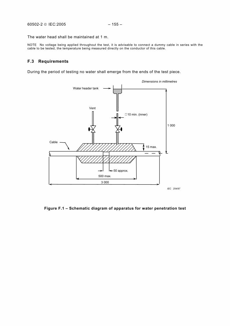
60502-2 IEC:2005 – 155 –
The water head shall be maintained at 1 m.
NOTE No voltage being applied throughout the test, it is advisable to connect a dummy cable in series with the cable to be tested, the temperature being measured directly on the conductor of this cable.
F.3 Requirements
During the period of testing no water shall emerge from the ends of the test piece.
Vent
1 000
3 000
Water header tank
50 approx.
500 max.
15 max.
∅ 10 min. (inner)
Cable
Dimensions in millimetres
IEC 254/97
Figure F.1 – Schematic diagram of apparatus for water penetration test
60502-2 IEC:2005 – 157 –
Bibliography
IEC 60287 (all parts), Electric cables – Calculation of the current rating
IEC 60502-1, Power cables with extruded insulation and their accessories for rated voltages from 1 kV (Um = 1,2 kV) up to 30 kV (Um = 36 kV) – Part 1: Cables for rated voltages of 1 kV (Um = 1,2 kV) and 3 kV (Um = 3,6 kV)
IEC 60853 (all parts), Calculation of the cyclic and emergency current rating of cables
___________


Standards Survey
The IEC would like to offer you the best quality standards possible. To make sure that wecontinue to meet your needs, your feedback is essential. Would you please take a minuteto answer the questions overleaf and fax them to us at +41 22 919 03 00 or mail them tothe address below. Thank you!
Customer Service Centre (CSC)
International Electrotechnical Commission3, rue de Varembé1211 Genève 20Switzerland
or
Fax to: IEC/CSC at +41 22 919 03 00
Thank you for your contribution to the standards-making process.
Non affrancareNo stamp required
Nicht frankierenNe pas affranchir
A Prioritaire
RÉPONSE PAYÉE
SUISSE
Customer Service Centre (CSC)International Electrotechnical Commission3, rue de Varembé1211 GENEVA 20Switzerland
Q1 Please report on ONE STANDARD andONE STANDARD ONLY . Enter the exactnumber of the standard: (e.g. 60601-1-1)
.............................................................
Q2 Please tell us in what capacity(ies) youbought the standard (tick all that apply).I am the/a:
purchasing agent R
librarian R
researcher R
design engineer R
safety engineer R
testing engineer R
marketing specialist R
other.....................................................
Q3 I work for/in/as a:(tick all that apply)
manufacturing R
consultant R
government R
test/certification facility R
public utility R
education R
military R
other.....................................................
Q4 This standard will be used for:(tick all that apply)
general reference R
product research R
product design/development R
specifications R
tenders R
quality assessment R
certification R
technical documentation R
thesis R
manufacturing R
other.....................................................
Q5 This standard meets my needs:(tick one)
not at all R
nearly R
fairly well R
exactly R
Q6 If you ticked NOT AT ALL in Question 5the reason is: (tick all that apply)
standard is out of date R
standard is incomplete R
standard is too academic R
standard is too superficial R
title is misleading R
I made the wrong choice R
other ....................................................
Q7 Please assess the standard in thefollowing categories, usingthe numbers:(1) unacceptable,(2) below average,(3) average,(4) above average,(5) exceptional,(6) not applicable
timeliness .............................................quality of writing....................................technical contents.................................logic of arrangement of contents ..........tables, charts, graphs, figures ...............other ....................................................
Q8 I read/use the: (tick one)
French text only R
English text only R
both English and French texts R
Q9 Please share any comment on anyaspect of the IEC that you would likeus to know:
............................................................
............................................................
............................................................
............................................................
............................................................
............................................................
............................................................
............................................................
............................................................
............................................................
............................................................
............................................................


ISBN 2-8318-7901-9
-:HSMINB=]\^UV\:ICS 29.060.20
Typeset and printed by the IEC Central Office GENEVA, SWITZERLAND