Internal Technical Standards
47
Ev. č. / Ev.-Nr. 3276 S5 ŠKODA AUTO a.s., tř. Václava Klementa 869, Mladá Boleslav II, 293 01 Mladá Boleslav, Czech Republic 1/47 Platnost od: 01.02.2020 Internal Technical Standards 1.21 HVAC Systems Updated on 2020-05-11 Prepared by Guaranteed by Approved by Pages Annexes Jač ek, PSU/3 Ing. Neděle, Slavík, Staněk ŠE-TS PSU/3 PS 47 Applies to delivery, installation and commissioning of HVAC equipment at ŠKODA AUTO Contents: A. Measurement and Regulation Part (M&R) ..................................................................................................................................................... 3 1. Standards, Regulations, Directives ................................................................................................................................................................. 3 2. Equipment Division .......................................................................................................................................................................................... 3 3. General Requirements for M&R System Design ............................................................................................................................................ 3 4. Type Schemes with Layout and Description of Required Peripheries .......................................................................................................... 7 5. Software – Implemented Design for Type Diagrams ................................................................................................................................... 13 B. Machinery Section ......................................................................................................................................................................................... 30 1. Supplier-Customer Relations ........................................................................................................................................................................ 30 2. Standards, Regulations, Guidelines, Legislation .......................................................................................................................................... 32 3. General Technical Regulations ..................................................................................................................................................................... 32 4 Measurement devices used: ......................................................................................................................................................................... 39
Transcript of Internal Technical Standards

Ev. č. / Ev.-Nr. 3276 S5 ŠKODA AUTO a.s., tř. Václava Klementa 869, Mladá Boleslav II, 293 01 Mladá Boleslav, Czech Republic 1/47Platnost od: 01.02.2020
Internal Technical Standards1.21 HVAC SystemsUpdated on 2020-05-11
Prepared by Guaranteed by Approved by Pages Annexes
Jaček, PSU/3Ing. Neděle, Slavík, Staněk ŠE-TS
PSU/3 PS 47
Applies to delivery, installation and commissioning of HVAC equipment at ŠKODA AUTO
Contents:
A. Measurement and Regulation Part (M&R) ..................................................................................................................................................... 3
1. Standards, Regulations, Directives ................................................................................................................................................................. 3
2. Equipment Division .......................................................................................................................................................................................... 3
3. General Requirements for M&R System Design ............................................................................................................................................ 3
4. Type Schemes with Layout and Description of Required Peripheries .......................................................................................................... 7
5. Software – Implemented Design for Type Diagrams ................................................................................................................................... 13
B. Machinery Section ......................................................................................................................................................................................... 30
1. Supplier-Customer Relations ........................................................................................................................................................................ 30
2. Standards, Regulations, Guidelines, Legislation .......................................................................................................................................... 32
3. General Technical Regulations ..................................................................................................................................................................... 32
4 Measurement devices used: ......................................................................................................................................................................... 39

Ev. č. / Ev.-Nr. 3276 S5 ŠKODA AUTO a.s., tř. Václava Klementa 869, Mladá Boleslav II, 293 01 Mladá Boleslav, Czech Republic 2/47Platnost od: 01.02.2020
Internal Technical Standards1.21 HVAC SystemsUpdated on 2020-05-11
The latest updated version of this ITS is available at the “http://cts.skoda-auto.com/” web site, the company is not obliged to notify their businesspartners on the ITS update.Therefore we strongly recommend that everybody checks the ITS regularly. These documents become valid on the date of their last update. Forthe contracts signed is decisive the validity of the ITS at the time of the order.Note: In case of any differences between the Czech, English or German language mutation of this ITS, the Czech version takes precedence.The Czech version is available at http://cts.skoda-auto.com/.
First release: 1993-01-11
Change number: Date: Note::
1. 1997-01-22 Pages 1, 22. 2002-02-01 Arial font, ŠKODA AUTO logotype3. 2007-07-01 Completely revised4. 2011-11-24 Completely revised5. 2012-02-28 Standards adjusted6. 2015-03-25 Completely revised7. 2016-06-27 Amendment of points 3.4.68. 2020-05-11 Completely revised

Ev. č. / Ev.-Nr. 3276 S5 ŠKODA AUTO a.s., tř. Václava Klementa 869, Mladá Boleslav II, 293 01 Mladá Boleslav, Czech Republic 3/47Platnost od: 01.02.2020
Internal Technical Standards1.21 HVAC SystemsUpdated on 2020-05-11
A. Measurement and Regulation Part (M&R)
1. Standards, Regulations, DirectivesAll electrical equipment, which also includes M&R equipment, must comply with the requirements stipulated by applicable acts, decrees,governmental regulations and technical standards.
2. Equipment DivisionFor the purposes of the present document, the HVAC equipment, which includes the M&R system design, is considered to be divided in two parts.
HVAC equipment up to 10,000 m3/h inclusiveHVAC equipment above 10,000 m3/h
2.1 HVAC equipment up to 10,000 m3/h inclusiveFor this type of equipment, autonomous M&R control units are allowed to be used. A connection of the aggregate failure and equipment operationsignals to the visualization system will be realized for every such system. The connection may be realized by ethernet communication module orusing outputs representing a circuit-opening potential-free contact for failure signalling, and a circuit-closing potential-free contact for operationsignalling. The failure output must ensure opening in the following equipment statuses:
- Fan electric motor failure (differential manostat or thermal protection – it may be used only if the motor is mounted on a common shaftwith the fan blades)
- Filter clogging (differential manostat)- Anti-freeze protection response (anti-freeze thermostat disconnects the equipment)
HVAC units serving a space with higher air quality requirements (precise air temperature or humidity monitoring etc.) and working with an air flowup to 10 000 m3/h need to be connected to the visualization system. The visualization will include all devices for ventilation and air conditioningof measuring centres, testing laboratories, charging stations and cafeterias. The connection of other HVAC equipment up to 10 000 m3/h to thevisualization system needs to be consulted with ŠE-TS – Energy Management. If there is an existing visualization system in the hall concerned,the signals should be connected to the existing system.Autonomous regulation must correspond to the equipment specified in Chapter 4 and to other requirements of this ITS; it is undesirable tosupplement the autonomous regulation by other regulators, such as PPK signals, emergency heating valves regulation, etc. – consultation ofrequirements with the ŠE-TS department – Energy Management, and PPB ŠA is necessary.
2.2 HVAC equipment above 10,000 m3/hFor equipment above 10,000 m3/h, free-programmable controllers provided by the following manufacturers will be used:
HONEYWELLSIEMENSSAIA
Each controller will be connected to the ŠKODA AUTO ethernet network – data socket must be provided (coordinated by the FIO department). Ifmore than one controller forms a part of the design documentation under preparation, they may be interconnected via their own communicationsystem during the project. In such a case, connecting only one of the controllers to the ethernet network will suffice. The controllers have to beequipped with the BACnet IP communication protocol.
3. General Requirements for M&R System DesignThe overall concept of major projects shall always be discussed with VS/1 and ŠE-TS (Ško-Energo – ES Dept., hereinafter referred toas "ŠE-TS")!
3.1 Controller Installation3.1.1 New Building or Overall Reconstruction of Existing BuildingAfter meeting with ŠE-TS, a control system supplied by one of the aforementioned manufacturers may be used that was approved during thismeeting.
3.1.2 Existing Building – Improvements, Additions to EquipmentAdditional controllers shall respect the existing topology of control substations (controllers) including the manufacturer!
3.2 Adding Components and Peripheries to Existing EquipmentIf it is considered to add more M&R elements to the HVAC equipment, the possibility of adding them to the existing control substation (if operational)shall be considered in the first place. A new substation will subsequently be installed if the existing control substation cannot be used.
3.3 Distribution Board and Controller NumberingController and M&R distribution board number will always be determined by ŠE-TS!
3.4 Installation of Control ValvesControl valves as per ITS 1.14 a 6.22 will be used for heating and cooling water control. Servo drives equipped with safety function (spring) –closes in the absence of voltage, will be used to install mixing valves in the hot-water system with a temperature gradient of 130/70°C!The control valves will always be installed in a supply line. A mixing valve for central heating system and a distributing valve for the cooling system.The control valves connected from hot-water line will always be of flange type, rated at nominal pressure PN16 and temperature 130°C.
3.5 Solution of Some Important Sequences

Ev. č. / Ev.-Nr. 3276 S5 ŠKODA AUTO a.s., tř. Václava Klementa 869, Mladá Boleslav II, 293 01 Mladá Boleslav, Czech Republic 4/47Platnost od: 01.02.2020
Internal Technical Standards1.21 HVAC SystemsUpdated on 2020-05-11
3.5.1 FloodingA flooding indicator switches off the HVAC equipment, closes a three-way mixing valve of the central heating system, possibly a three-waydistributing valve of the cooling system and emergency gates on central heating and cooling water supply line to the HVAC machine room. Servodrives on emergency gates are used with an emergency function (using a spring to close in absence of voltage). In case of drop in water levelsensed by flooding indicator, HVAC operation will be neither automatically recovered, nor emergency valves will be opened on medium supplyline to the machine room. Operation can only be recovered when the failure has been remedied and manual unlocking has been unlocked on thesubstation control panel.
3.5.2 Rotating RecuperatorRotating recuperator speed is controlled by a frequency converter within the range of 0-100%. A temperature sensor in the exhaust linedownstream of the recuperator reduces its speed at temperature of +5°C - danger of frost formation. For HVAC equipment designed to provideventilation for high humid areas (canteen, regeneration, etc.), the exhaust line will be additionally equipped with a humidity sensor.3.5.3 Plate Heat ExchangerAir flow through a plate heat exchanger can be controlled by a bypass (short-circuit) flap in the supply line. A temperature sensor in the exhaustline downstream of the plate heat exchanger will open the bypass flap when reaching the temperature of +5°C – danger of frost formation. ForHVAC equipment designed to provide ventilation for high humid areas (canteen, regeneration, etc.), the exhaust line will be additionally equippedwith a humidity sensor.
3.5.4 Anti-Freeze Thermostat and Temperature Sensor of Heater Return PipeA safety anti-freeze thermostat with a capillary tube of a sufficient length (1st stage of anti-freeze protection), mounted downstream of the heater,will switch off the HVAC unit at drop in temperature below +5°C, will close flaps in supply line and exhaust line, will fully open a three-way mixingvalve of the heater and will ensure pump operation. After warming through the heater, its heat output will be reduced, possibly three-way mixingvalve will be closed. Heater warming-through is sensed either by a clamp-on temperature sensor on piping or by a stem-type temperature sensordirectly in heating water pipeline – return pipe (2nd stage of anti-freeze protection). A decision temperature for switching off the HVAC equipmentis +10°C. It must be possible to reset the anti-freeze thermostat automatically from the station without the necessity of unlocking directly on thethermostat.
For outdoor-mounted HVAC equipment, in winter season – outdoor temperature =< +5°C, with HVAC unit switched off, a return pipe temperaturesensor will be controlled by the three-way mixing valve so as to reach a constant temperature of +30°C on return pipe from the heater. A circulatingpump will remain permanently in operation.
3.5.5 Servo Drives for Flaps - Supply and Exhaust Lines
3.5.5-1 Water Heating or CoolingServo drives for flaps on supply and exhaust lines will be provided with a safety function – a spring. These servo drives close HVAC piping inabsence of voltage by means of a mechanical spring. Flaps are opened according to the selected algorithm together with startup of HVAC unitand closed always with switching off. If operational switching off is involved, a short range of equipment can be set for cooling down heaterchamber. However, in case of an emergency shutdown of the HVAC unit, the flaps are closed immediately! These flaps should be mounted asclose as possible to the inlet of suction (exhaust) pipe to the building.
3.5.5-2 Electrical Heating or Cooling Unit with Direct EvaporatorServo drives for flaps on supply and exhaust lines need not be provided with a safety function – a spring. These servo drives close the HVACpiping only based on the signal sent by control substation (no danger of water elements freezing). Flaps are opened according to the selectedalgorithm together with startup of HVAC unit and closed always with delayed switching off.
3.5.6 Differential ManostatsThey will be installed on fans and filters. Opening of differential manostat on fan (supply or exhaust) will cause the HVAC unit to shut down. Ifelectrical heating is used for HVAC unit, the supply fan will be switched off with delay. Opening of differential manostat on filter will be signaled onthe control panel. The HVAC unit will be shut down with time delay – by the type of the space, from which the equipment sucks off. It is notnecessary to install the differential manostat for fan motor if the motor is mounted on a common shaft with fan blades. In this case, a failureindication provided only by thermal protection will be sufficient.
3.5.7 Cooling UnitsA cooling unit failure will be signaled in the MaR system – each cooling circuit separately. The MaR system will be provided with an option ofshutting down the cooling unit at outdoor temperature t=<5°C, which will be monitored for 24 hours. This mode does not apply to cooling equipmentdesigned to provide a partial humidity removal or for technology. Each cooling unit will be provided for year-round operation. If the cooling unit willbe designed as water-cooling unit, self-regulating heating cables will be applied to the piping conducted in the exterior. Their control will be ensuredby the control system depending on outdoor temperature. With temperature below +5°C, the cables will be attached to the power supply and willheat up the piping. With temperature above +5°C, the heating cables will be detached.
3.5.8 PumpsA pump will be protected in compliance with the documentation, data sheet and manufacturer's recommendation. For WILO pumps equipped withthe WSK terminals, the SK622 accessories will be used for its closing and protection.The pump will be protected against dry operation by an electrical motor load sensor Emotron M20. If this device evaluates that the load deviatesfrom the pre-set values, the pump will not be started and the HVAC equipment will indicate an error. In case when this protection is provided byintegrated electronics of the pump, Emotron is not installed.In case of change of pump type during implementation, all design parameters must be kept including electrical connection! If this is not possible,the change must be consulted with the M&R system designer.
3.5.9 Fire Dampers and Electrical Fire Alarm System (EFS)The M&R system senses the conditions of fire dampers. Closure of fire damper results in disconnection of the relevant HVAC unit. Each signalprovided by the fire damper will be sent to a terminal board in a transfer box of the EFS system, placed at the M&R distribution board. One digitalinput from the control substation will also be sent to the terminal board in the transfer box of the EFS system. A signal brought to this input will

Ev. č. / Ev.-Nr. 3276 S5 ŠKODA AUTO a.s., tř. Václava Klementa 869, Mladá Boleslav II, 293 01 Mladá Boleslav, Czech Republic 5/47Platnost od: 01.02.2020
Internal Technical Standards1.21 HVAC SystemsUpdated on 2020-05-11
result in disconnection of all HVAC equipment. In case of switching off the HVAC unit using the main switch or STOP pushbutton, the EFS systemmust not be put into operation.
3.5.10 Distribution BoardsM&R distribution boards will be marked "BA".Power distribution boards relevant to M&R distribution boards will be marked "RM".Distribution board serial numbers will be determined by the ŠE-TS - Energy Management department according to equipment marking on theindividual buildings. It must be in compliance with the marking of the relevant HVAC device.Distribution board boxes, if separate for power part and MaR part, must be of the same type and size. Box-type distribution boards must beequipped with pedestals.Distribution boards will be equipped with uniform locks of 1333 type; descriptions will be provided on engraved labels. Marking and point ofconnection of the distribution board will be fixed on distribution board door.Distribution boards installed in production halls or other facilities where they are exposed to a risk of damage by means of transportation (forklifts)etc. must be protected with steel barriers.Every distribution board for HVAC power supply will be equipped with an electrometer with data transfer to the EBI visualization, or Energis whereapplicable. If the HVAC is connected to the distribution board parallelly to another technology, energy consumption will be measured specificallyfor the output leading to the HVAC.The distribution board has to be located in an interior area of the object, or, shall external placement be necessary (such as on a roof), has to belocated in a separate cabinet outside the HVAC unit or in a separate protective cabinet providing the permissible operation temperature for controlpanels, regulators, and other MaR elements.
3.5.11 Cable ChannelsWe require placement of cable channels outside the HVAC service area, so that access to the unit chambers is unrestricted.
3.6 Electrical Safety and Control ElementsEach HVAC device can be switched off (service switch-off) using the switch located on the HVAC unit or in sight of direct view of a serviceemployee. This switch can directly cut off motor power supply or turn off electromagnetic opening elements in the distribution board.Each M&R distribution board will be equipped with a safety STOP pushbutton, located on the distribution board door. The STOP pushbutton ofXAL-K174E - SCHNEIDER type with a locking device can be used in enclosed, locked machine rooms... When the distribution boards are locatedin unlocked areas, the STOP pushbutton under glass of GW 42201 GEWISS type will be used. A yellow frame with an overlap of 5 cm should bemanufactured and placed under this box.
An actuator 0/AUT (off/automatic mode) used to control the HVAC equipment will be located on distribution board door in an enclosed machineroom. An actuator in a freely accessible area (HVAC equipment closing, fan speed changeover, etc.) will always be provided with a key of the 455type.
The 0/AUT switch on the distribution board will always be superior to an actuator in an open area! In the case of a service intervention on theHVAC equipment, the employee will first turn this 0/AUT switch to "0" position and then shut down the HVAC equipment (motors) in a safe mannerusing the switch located on the HVAC unit (or in direct sight).
3.7 Alarm System and Information Concerning Equipment StatusAll controllers (or a group of controllers in one distribution board) will be equipped with a graphic interface, located in distribution board door.
Distribution board door will be provided with the following indicator lamps:- distribution board live - white- HVAC unit operation - green- HVAC unit failure - yellow- pump operation - green
For multiple HVAC units controlled from one distribution board, operation and failure indicator lamps will be installed for each of them. The indicatorlamps will be connected to 24 VAC power supply.All indicator lamps will be used with LED light source. For controllers, where the digital output comprises of a triac, conversion relays (LED will notbe connected directly from controller digital output) will always be used for controlling the indicator lamps.FAILURE STATES NEED TO BE SIGNALLED WITH A CONTINUOUS SIGNAL, NOT WITH A FLASHING INDICATOR LAMP (Otherwise, aproprietary data point needs to be created for an aggregate failure with a constant status to be transferred to visualization.).
3.8 Peripheries – Use and Connection
3.8.1 Temperature Sensors in HVAC PipingThey will be used with a stem of an appropriate length. Sensors with an increased resistance in polluted air will be used upstream of filters on theside of supply and exhaust line (outdoor air and space exhaust air temperature).
3.8.2 Temperature Sensors in SpaceThis effect (environment specification is contained in the report concerning identification of external influences) will be taken into consideration indesigning a sensor type for plants with increased pollution or with the requirements for higher IP rating (humidity).
3.9 Connecting Peripheries to Controller- Temperature and pressure sensors will always be connected to their own controller analogue input.- Differential manostats – each one has its own controller digital input- Anti-freeze thermostat – its own controller digital input converted through a relay, directly shutting down fans. For a HVAC unit located
outdoors, having a large area of water heater or cooler, two anti-freeze thermostats with 6 m long capillary tube will be installed to coversufficiently the entire space, through which the supply air flows. The two anti-freeze thermostats will be connected in series. Thisperiphery will be connected neither through extension LON modules nor through signal converters (e.g. UDI 6). This provision shall notapply to control substations operating only with I/O LON modules. In this case, HVAC unit disconnection with closure of inlet and exhaustflaps must be designed without using the control substation.
Ev. č. / Ev.-Nr. 3276 S5 ŠKODA AUTO a.s., tř. Václava Klementa 869, Mladá Boleslav II, 293 01 Mladá Boleslav, Czech Republic 6/47Platnost od: 01.02.2020
Internal Technical Standards1.21 HVAC SystemsUpdated on 2020-05-11
- HVAC machine room flooding indicator – it should always be used when the HVAC machine room is located above the technology orthe potentially dangerous process or space. The indicator will be connected to its own digital input in the control substation. Emergencyvalves will be closed directly from the flooding indicator.
3.10 HVAC Equipment Operation Actuators Located in SpaceWhen using actuators located in ventilated or adjacent areas (i.e., not on the distribution board), these must be provided with an operationindicator! These actuators must be illegibly and permanently marked. We recommend that other types of actuators be used than the types usedfor the lighting system.

Ev. č. / Ev.-Nr. 3276 S5 ŠKODA AUTO a.s., tř. Václava Klementa 869, Mladá Boleslav II, 293 01 Mladá Boleslav, Czech Republic 7/47Platnost od: 01.02.2020
Internal Technical Standards1.21 HVAC SystemsUpdated on 2020-05-11
3.11 Protecting HVAC Equipment Against Water LeaksFor newly installed and also existing M&R systems used for HVAC equipment, which poses a risk of damage to the technology, buildings andother equipment due to HVAC leakage and of loss of production, the control system must be equipped with a sensor of the level of leakingwater, and there must be electrical stop valves installed on the supply line and return line in the water system for heating or cooling.An electronic device used to sense the water level shall be installed in the M&R distribution board. If there is a lack of space in the existingdistribution boards, the device can be installed in a separate box. The terminals of the device should be used to connect the sensing electrodes.The cable shall be installed together with other M&R cables for the HVAC equipment. If the device is located in a machine room with animpermeable floor, then the sensing electrodes should be installed in the lowest point of the machine room floor (gulley, tank under HVAC) - theplanner should determine a suitable point.A relay will be connected to the output contact of the electronic level sensor, the contacts of which will close the electrical valves on the supplyline and return line. The valve servo drives will be equipped with motors with a spring that will close the valve even in the case of power outage.The relay contact of the water level sensor will be used to bring the signal to the control system, which will shut down the HVAC equipment. Thecontrol system output will be used to signal an emergency status. If the system is connected to a superior visualization system, the status willalso be recorded in the control centre. For existing control systems, where a capacity reserve of inputs is not established prior toimplementation, the relay contact of the water level sensor will be used to disconnect the control voltage for HVAC control, which will shut downthe HVAC equipment. The flooding level will be signalled optically or in combination with an acoustic signal to a place where an operator ormaintenance staff is permanently present.
4. Type Schemes with Layout and Description of Required Peripheries
4.1 HVAC Equipment - Type 1
Sensors:- BT1 - Temperature - outdoor air – upstream of a flap in HVAC supply piping.- BT2 - Temperature - mixed air – in HVAC piping, downstream of supply-exhaust mixing.- BT3 - Temperature - heater return pipe – clamp on central heating return pipe from HVAC heater- BT4 - Temperature - air supplied to a space – in HVAC piping, on HVAC unit outlet or in piping- BT5 - Temperature – space- BT6 - Temperature - air exhausted from the space – in HVAC piping on unit exhaust line
Differential manostats:- SP1 - Supply fan – closes after reaching a differential pressure- SP2 - Exhaust fan - closes after reaching a differential pressure- SP3 - Filter in supply line – opens after reaching a preset differential pressure- SP4 - Filter in exhaust line - opens after reaching a preset differential pressure
Servo drives:- M4 - Three-way control valve for heater in HVAC piping – servo drive with proportional control- M5 - Flap in supply line – upstream of HVAC unit – servo drive with safety spring (closes in absence of voltage). Proportional control.- M6 - Flap in exhaust line – downstream of HVAC unit – servo drive with safety spring (closes in absence of voltage). Proportional
control.- M7 - MIX flap – servo drive with proportional control

Ev. č. / Ev.-Nr. 3276 S5 ŠKODA AUTO a.s., tř. Václava Klementa 869, Mladá Boleslav II, 293 01 Mladá Boleslav, Czech Republic 8/47Platnost od: 01.02.2020
Internal Technical Standards1.21 HVAC SystemsUpdated on 2020-05-11
- M11 - Three-way distributing valve for water cooler in HVAC piping – servo drive with proportional control
Anti-freeze thermostat:- ST1 - An anti-freeze thermostat with 6m long capillary tube evenly distributed over the hot-water exchanger will be used! It opens at
temperature =<+5°C.
Motors:- M1 - supply fan- M2 - exhaust fan- M3 - circulation pump for heating- M10 - circulation pump for cooling
4.2 HVAC Equipment - Type 2
Sensors:- BT1 - Temperature - outdoor air – upstream of a flap in HVAC supply piping.- BT2 - Temperature - mixed air – in HVAC piping, downstream of rotating recuperator in supply line.- BT3 - Temperature - heater return pipe – clamp on central heating return pipe from HVAC heater- BT4 - Temperature - air supplied to a space – in HVAC piping, on HVAC unit outlet or in piping- BT5 - Temperature – space- BT6 - Temperature - air exhausted from the space – in HVAC piping on unit exhaust line- BT7 - Air temperature - downstream of recuperator - in HVAC piping, downstream of rotating recuperator in exhaust line
Differential manostats:- SP1 - Supply fan – closes after reaching a differential pressure- SP2 - Exhaust fan - closes after reaching a differential pressure- SP3 - Filter in supply line – opens after reaching a preset differential pressure- SP4 - Filter in exhaust line - opens after reaching a preset differential pressure
Servo drives:- M4 - Three-way control valve for heater in HVAC piping – servo drive with proportional control- M5 - Flap in supply line – upstream of HVAC unit – servo drive with safety spring (closes in absence of voltage). Bang-bang control.- M6 - Flap in exhaust line – downstream of HVAC unit – servo drive with safety spring (closes in absence of voltage). Bang-bang
control.- M7 - MIX flap – servo drive with bang-bang control (rotating recuperator and short-circuit flap combination) – fast flooding function.- M 8,9 - Rotating recuperator drive with a frequency converter- M11 - Three-way distributing valve for water cooler in HVAC piping – servo drive with proportional control
Anti-freeze thermostat:- ST1 - An anti-freeze thermostat with 6m long capillary tube evenly distributed over the hot-water exchanger will be used! It opens at
temperature =<+5°C.

Ev. č. / Ev.-Nr. 3276 S5 ŠKODA AUTO a.s., tř. Václava Klementa 869, Mladá Boleslav II, 293 01 Mladá Boleslav, Czech Republic 9/47Platnost od: 01.02.2020
Internal Technical Standards1.21 HVAC SystemsUpdated on 2020-05-11
Motors:- M1 - supply fan- M2 - exhaust fan- M3 - circulation pump for heating- M10 - circulation pump for cooling
4.3 HVAC Equipment - Type 2.1 – High Humidity Areas
Sensors:- BT1 - Temperature - outdoor air – upstream of a flap in HVAC supply piping.- BT2 - Temperature - mixed air – in HVAC piping, downstream of rotating recuperator in supply line.- BT3 - Temperature - heater return pipe – clamp on central heating return pipe from HVAC heater- BT4 - Temperature - air supplied to a space – in HVAC piping, on HVAC unit outlet or in piping- BT5 - Temperature – space- BT6 - Temperature - air exhausted from the space – in HVAC piping on unit exhaust line- BT7 - Air temperature - downstream of recuperator - in HVAC piping, downstream of rotating recuperator in exhaust line- BH4 - Humidity - exhausted from the space – in HVAC piping, on unit exhaust line
Differential manostats:- SP1 - Supply fan – closes after reaching a differential pressure- SP2 - Exhaust fan - closes after reaching a differential pressure- SP3 - Filter in supply line – opens after reaching a preset differential pressure- SP4 - Filter in exhaust line - opens after reaching a preset differential pressure
Ev. č. / Ev.-Nr. 3276 S5 ŠKODA AUTO a.s., tř. Václava Klementa 869, Mladá Boleslav II, 293 01 Mladá Boleslav, Czech Republic 10/47Platnost od: 01.02.2020
Internal Technical Standards1.21 HVAC SystemsUpdated on 2020-05-11
Servo drives:- M4 - Three-way control valve for heater in HVAC piping – servo drive with proportional control- M5 - Flap in supply line – upstream of HVAC unit – servo drive with safety spring (closes in absence of voltage). Bang-bang control.- M6 - Flap in exhaust line – downstream of HVAC unit – servo drive with safety spring (closes in absence of voltage). Bang-bang
control.- M7 - MIX flap – servo drive with bang-bang control (rotating recuperator and short-circuit flap combination) – fast flooding function.- M 8,9 - Rotating recuperator drive with a frequency converter- M11 - Three-way distributing valve for water cooler in HVAC piping – servo drive with proportional control
Anti-freeze thermostat:- ST1 - An anti-freeze thermostat with 6m long capillary tube evenly distributed over the hot-water exchanger will be used! It opens at
temperature =<+5°C.
Motors:- M1 - supply fan- M2 - exhaust fan- M3 - circulation pump for heating- M10 - circulation pump for cooling
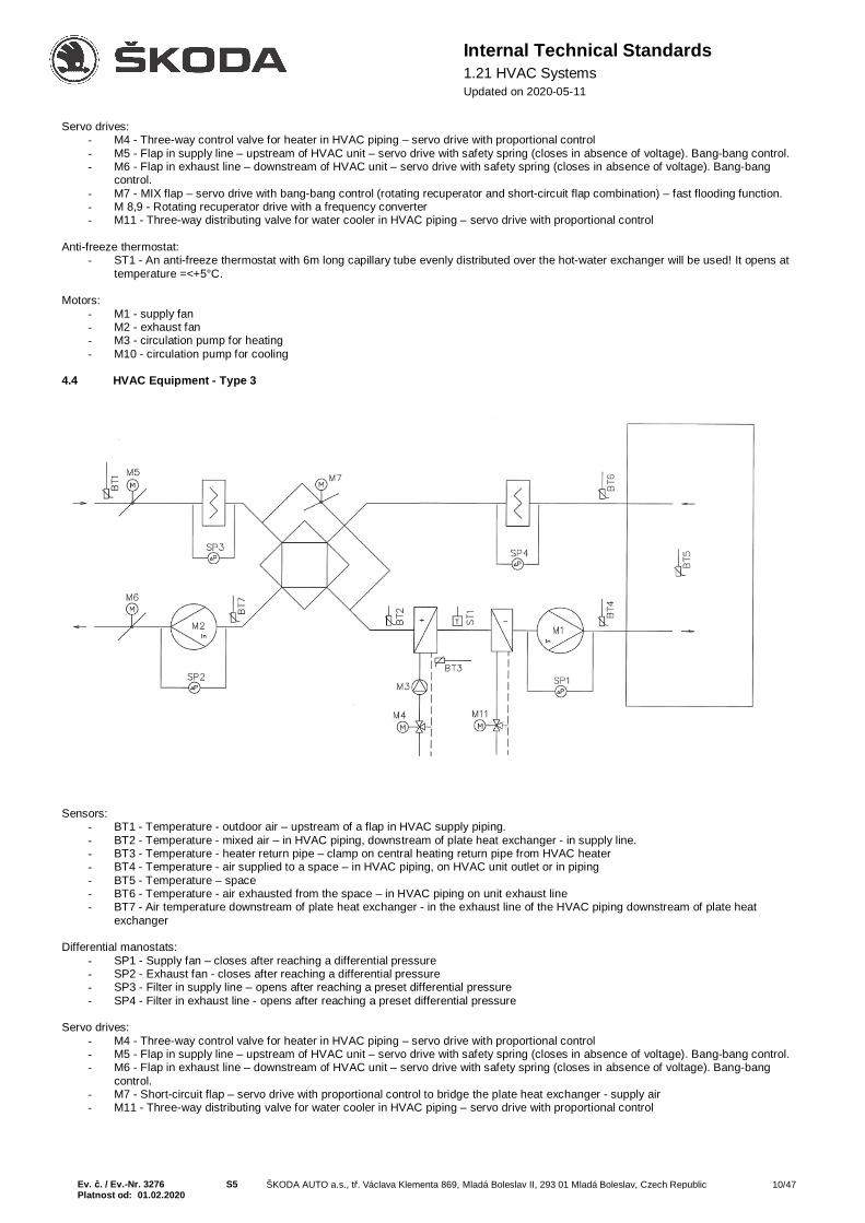
4.4 HVAC Equipment - Type 3
Sensors:- BT1 - Temperature - outdoor air – upstream of a flap in HVAC supply piping.- BT2 - Temperature - mixed air – in HVAC piping, downstream of plate heat exchanger - in supply line.- BT3 - Temperature - heater return pipe – clamp on central heating return pipe from HVAC heater- BT4 - Temperature - air supplied to a space – in HVAC piping, on HVAC unit outlet or in piping- BT5 - Temperature – space- BT6 - Temperature - air exhausted from the space – in HVAC piping on unit exhaust line- BT7 - Air temperature downstream of plate heat exchanger - in the exhaust line of the HVAC piping downstream of plate heat
exchanger
Differential manostats:- SP1 - Supply fan – closes after reaching a differential pressure- SP2 - Exhaust fan - closes after reaching a differential pressure- SP3 - Filter in supply line – opens after reaching a preset differential pressure- SP4 - Filter in exhaust line - opens after reaching a preset differential pressure
Servo drives:- M4 - Three-way control valve for heater in HVAC piping – servo drive with proportional control- M5 - Flap in supply line – upstream of HVAC unit – servo drive with safety spring (closes in absence of voltage). Bang-bang control.- M6 - Flap in exhaust line – downstream of HVAC unit – servo drive with safety spring (closes in absence of voltage). Bang-bang
control.- M7 - Short-circuit flap – servo drive with proportional control to bridge the plate heat exchanger - supply air- M11 - Three-way distributing valve for water cooler in HVAC piping – servo drive with proportional control

Ev. č. / Ev.-Nr. 3276 S5 ŠKODA AUTO a.s., tř. Václava Klementa 869, Mladá Boleslav II, 293 01 Mladá Boleslav, Czech Republic 11/47Platnost od: 01.02.2020
Internal Technical Standards1.21 HVAC SystemsUpdated on 2020-05-11
Motors:- M1 - supply fan- M2 - exhaust fan- M3 - circulation pump for heating- M10 - circulation pump for cooling
Anti-freeze thermostat:- ST1 - An anti-freeze thermostat with 6m long capillary tube evenly distributed over the hot-water exchanger will be used! It opens at
temperature =<+5°C.4.5 HVAC Equipment - Type 3.1 – High Humidity Areas
Sensors:- BT1 - Temperature - outdoor air – upstream of a flap in HVAC supply piping.- BT2 - Temperature - mixed air – in HVAC piping, downstream of plate heat exchanger - in supply line.- BT3 - Temperature - heater return pipe – clamp on central heating return pipe from HVAC heater- BT4 - Temperature - air supplied to a space – in HVAC piping, on HVAC unit outlet or in piping- BT5 - Temperature in the space - informative- BT6 - Temperature - air exhausted from the space – in HVAC piping on unit exhaust line- BT7 - Air temperature downstream of plate heat exchanger - in the exhaust line of the HVAC piping downstream of plate heat exchanger- BH4 - Humidity - exhausted from the space – in HVAC piping, on unit exhaust line
Differential manostats:- SP1 - Supply fan – closes after reaching a differential pressure- SP2 - Exhaust fan - closes after reaching a differential pressure- SP3 - Filter in supply line – opens after reaching a preset differential pressure- SP4 - Filter in exhaust line - opens after reaching a preset differential pressure

Ev. č. / Ev.-Nr. 3276 S5 ŠKODA AUTO a.s., tř. Václava Klementa 869, Mladá Boleslav II, 293 01 Mladá Boleslav, Czech Republic 12/47Platnost od: 01.02.2020
Internal Technical Standards1.21 HVAC SystemsUpdated on 2020-05-11
Servo drives:- M4 - Three-way control valve for heater in HVAC piping – servo drive with proportional control- M5 - Flap in supply line – upstream of HVAC unit – servo drive with safety spring (closes in absence of voltage). Bang-bang control.- M6 - Flap in exhaust line – downstream of HVAC unit – servo drive with safety spring (closes in absence of voltage). Bang-bang control.- M7 - Short-circuit flap – servo drive with proportional control to bridge the plate heat exchanger - supply air- M11 - Three-way distributing valve for water cooler in HVAC piping – servo drive with proportional control
Motors:- M1 - supply fan- M2 - exhaust fan- M3 - circulation pump for heating- M10 - circulation pump for cooling
Anti-freeze thermostat:- ST1 - An anti-freeze thermostat with 6m long capillary tube evenly distributed over the hot-water exchanger will be used! It opens at
temperature =<+5°C.
4.6 HVAC Equipment - Type 4 – High Humidity Areas
Sensors:- BT1 - Temperature - outdoor air – upstream of a flap in HVAC supply piping.- BT2 - Temperature - mixed air – in HVAC piping, downstream of supply-exhaust mixing.- BT3 - Temperature - heater return pipe – clamp on central heating return pipe from HVAC heater- BT4 - Temperature - air supplied to a space – in HVAC piping, on HVAC unit outlet or in piping- BT5 - Temperature – space- BT6 - Temperature - air exhausted from the space – in HVAC piping on unit exhaust line- BH1 - Humidity - outdoors- BH2 - Humidity of the air supplied to the space – in HVAC piping, on HVAC unit outlet or in piping- BH3 - Space humidity- BH4 - Humidity - exhausted from the space – in HVAC piping, on unit exhaust line
Differential manostats:- SP1 - Supply fan – closes after reaching a differential pressure- SP2 - Exhaust fan - closes after reaching a differential pressure- SP3 - Filter in supply line – opens after reaching a preset differential pressure- SP4 - Filter in exhaust line - opens after reaching a preset differential pressure- Servo drives:- M4 - Three-way control valve for heater in HVAC piping – servo drive with proportional control- M5 - Flap in supply line – upstream of HVAC unit – servo drive with safety spring (closes in absence of voltage). Proportional control.

Ev. č. / Ev.-Nr. 3276 S5 ŠKODA AUTO a.s., tř. Václava Klementa 869, Mladá Boleslav II, 293 01 Mladá Boleslav, Czech Republic 13/47Platnost od: 01.02.2020
Internal Technical Standards1.21 HVAC SystemsUpdated on 2020-05-11
- M6 - Flap in exhaust line – downstream of HVAC unit – servo drive with safety spring (closes in absence of voltage). Proportionalcontrol.
- M7 - MIX flap – servo drive with proportional control- M11 - Three-way distributing valve for water cooler in HVAC piping – servo drive with proportional control
Anti-freeze thermostat:- ST1 - An anti-freeze thermostat with 6m long capillary tube evenly distributed over the hot-water exchanger will be used! It opens at
temperature =<+5°C.
Motors:- M1 - supply fan- M2 - exhaust fan- M3 - circulation pump for heating- M10 - circulation pump for cooling
4.7 HVAC Equipment - Type 5 - Technology Exhaust
Differential manostats:- SP2 - Exhaust fan - closes after reaching a differential pressure- SP4 - Filter in exhaust line - opens after reaching a preset differential pressure
Servo drives:- M21 - Flap in the main exhaust line – a bang-bang servo drive with safety spring.- M22 - Flap in the bypass pipe leading back to the hall – a bang-bang servo drive with safety spring.
Motors:- M20 - exhaust fan
Control:- Controller in the space with 0/1 switch module and operation and failure signalling lamps, and the same in the distribution board for the
exhaust apparatus.
5. Software – Implemented Design for Type Diagrams
5.1 General Description of DDC Programming for HVAC1) The environment for the control of and orientation in access to data points must be a standard operating system and be functionally consistentwith the operating system and the service procedure of the equipment installed so far in the Mladá Boleslav plant of ŠKODA AUTO a.s. (Forexample, a standard environment delivered together with the Honeywell systems of the Eagle/Hawk series – Czech version.)
2) Control function (control sequence) of each controller is ensured by control SW that must be prepared in accordance with the project forparticular equipment function. The operation of each controller must be fully autonomous (island operation). This condition does not have to be

Ev. č. / Ev.-Nr. 3276 S5 ŠKODA AUTO a.s., tř. Václava Klementa 869, Mladá Boleslav II, 293 01 Mladá Boleslav, Czech Republic 14/47Platnost od: 01.02.2020
Internal Technical Standards1.21 HVAC SystemsUpdated on 2020-05-11
met in cases of applications making use of transfer of data points between controllers. However, in this case, maintenance and operating personnelmust be notified of the fact.Controllers can differ in the number of attachable HW I/O (inputs/outputs) and the station must further enable the operator to access the applicationSW, which means a possibility of monitoring current values and failure conditions, setting basic control parameters, program parameters and time-program parameters, etc. Access is possible by connecting an external control panel or an integrated control panel with LCD display
3) The controller name must identify a type of applied program related to connected process equipment. This name is important in loading theprogram into the controller or in accessing the controller from CMS (Central Monitoring System). The name will be unique in the entire system.Each of the points and their values and states must be marked according to the pattern provided in the Annex (Table 1 and Table 2) to thisdescription
Point name structure:
3_A_ZZT_M223_x_xxxxxxx = equipment identification (e.g., HVAC No. 3) - unique within the hall or room
x_A_xxxxxxx = point type (e.g., failure, measurement, ...)
M – Measurement (analogue values obtained primarily from temperature and pressure sensors, heatmeters, etc.)
P – Command (direct commands to actuators, which may be used for service purposes for manual controlof these elements – pumps, valves, etc.)
A – Alarm (all failures from digital inputs as well as those generated by the controller program)S – Status (mostly digital inputs - active element feedback)O – Control (parameters for controlling the individual circuits – on/off central heating, domestic hot water,
central heating mode control, pump and valve spinning, etc.)N – Setting (parameters for entering the required values – required temperatures, pressures, equithermal
curve setting, etc.)V – Results (parameters displaying final values from internal controller algorithms – final equithermal
temperature, etc.)H – operating Hours
x_x_ZZT_M22 = point description (for example, recuperator ZZT motor M22) – see Tables 1 and 2.
4) In those cases when individual controllers form a group of devices with common operating mode and devices are interconnected by acommunication line, or the controller is added into the existing group of devices interconnected by a communication line, common control ofequipment operating modes by means of common time programs should be taken into consideration in creating the application SW.
5) After completion of installation, the installed application must be saved in EPROM memory of DDC station, if provided.
6) Documentation for DDC station must include a listing of installed SW generated in programming environment and its backup on CD, togetherwith function description of control sequences used in application and specification of function description of important points and their operation.
7) Explanation of abbreviations in function description of HVAC control sequences.
Analogue input (AI)- (e.g. temperature, pressure, humidity measurements)Analogue output (AO)- (e.g. output 0 -10 V for valve drive control)Digital input (DI)- (e.g. pump, fan operation)Digital output (DO) - (e.g. pump, fan, horn control)Virtual analog (VA) - (e.g. required temperature)Virtual digital (VD)- (e.g. an auxiliary D.B. for pump spins in summer operation)
8) Annex:Names of items in the annex are assigned at random, with no relation to the examples described hereinafter in ITS, to make the example easierto understand.
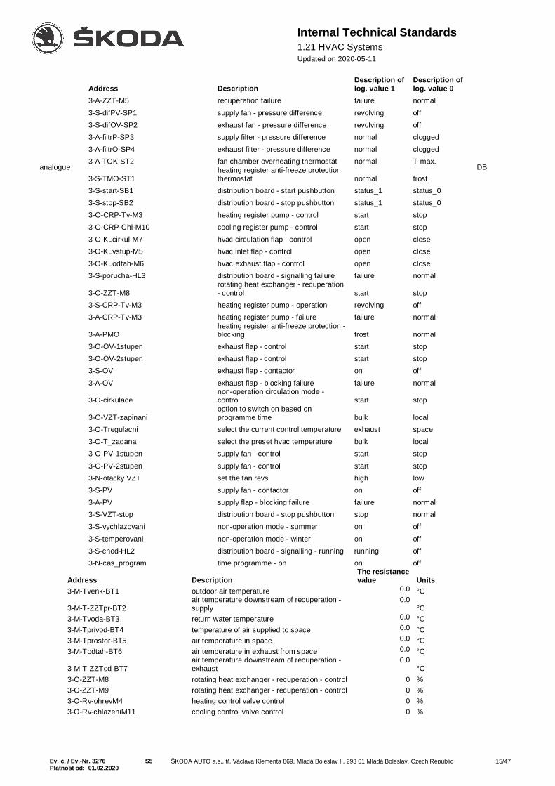
Tab.1 – digital DB
Ev. č. / Ev.-Nr. 3276 S5 ŠKODA AUTO a.s., tř. Václava Klementa 869, Mladá Boleslav II, 293 01 Mladá Boleslav, Czech Republic 15/47Platnost od: 01.02.2020
Internal Technical Standards1.21 HVAC SystemsUpdated on 2020-05-11
analogue DB
Address DescriptionThe resistancevalue Units
3-M-Tvenk-BT1 outdoor air temperature 0.0 °C
3-M-T-ZZTpr-BT2air temperature downstream of recuperation -supply
0.0°C
3-M-Tvoda-BT3 return water temperature 0.0 °C3-M-Tprivod-BT4 temperature of air supplied to space 0.0 °C3-M-Tprostor-BT5 air temperature in space 0.0 °C3-M-Todtah-BT6 air temperature in exhaust from space 0.0 °C
3-M-T-ZZTod-BT7air temperature downstream of recuperation -exhaust
0.0°C
3-O-ZZT-M8 rotating heat exchanger - recuperation - control 0 %3-O-ZZT-M9 rotating heat exchanger - recuperation - control 0 %3-O-Rv-ohrevM4 heating control valve control 0 %3-O-Rv-chlazeniM11 cooling control valve control 0 %
Address DescriptionDescription oflog. value 1
Description oflog. value 0
3-A-ZZT-M5 recuperation failure failure normal3-S-difPV-SP1 supply fan - pressure difference revolving off3-S-difOV-SP2 exhaust fan - pressure difference revolving off3-A-filtrP-SP3 supply filter - pressure difference normal clogged3-A-filtrO-SP4 exhaust filter - pressure difference normal clogged3-A-TOK-ST2 fan chamber overheating thermostat normal T-max.
3-S-TMO-ST1heating register anti-freeze protectionthermostat normal frost
3-S-start-SB1 distribution board - start pushbutton status_1 status_03-S-stop-SB2 distribution board - stop pushbutton status_1 status_03-O-CRP-Tv-M3 heating register pump - control start stop3-O-CRP-Chl-M10 cooling register pump - control start stop3-O-KLcirkul-M7 hvac circulation flap - control open close3-O-KLvstup-M5 hvac inlet flap - control open close3-O-KLodtah-M6 hvac exhaust flap - control open close3-S-porucha-HL3 distribution board - signalling failure failure normal
3-O-ZZT-M8rotating heat exchanger - recuperation- control start stop
3-S-CRP-Tv-M3 heating register pump - operation revolving off3-A-CRP-Tv-M3 heating register pump - failure failure normal
3-A-PMOheating register anti-freeze protection -blocking frost normal
3-O-OV-1stupen exhaust flap - control start stop3-O-OV-2stupen exhaust flap - control start stop3-S-OV exhaust flap - contactor on off3-A-OV exhaust flap - blocking failure failure normal
3-O-cirkulacenon-operation circulation mode -control start stop
3-O-VZT-zapinanioption to switch on based onprogramme time bulk local
3-O-Tregulacni select the current control temperature exhaust space3-O-T_zadana select the preset hvac temperature bulk local3-O-PV-1stupen supply fan - control start stop3-O-PV-2stupen supply fan - control start stop3-N-otacky VZT set the fan revs high low3-S-PV supply fan - contactor on off3-A-PV supply flap - blocking failure failure normal3-S-VZT-stop distribution board - stop pushbutton stop normal3-S-vychlazovani non-operation mode - summer on off3-S-temperovani non-operation mode - winter on off3-S-chod-HL2 distribution board - signalling - running running off3-N-cas_program time programme - on on off

Ev. č. / Ev.-Nr. 3276 S5 ŠKODA AUTO a.s., tř. Václava Klementa 869, Mladá Boleslav II, 293 01 Mladá Boleslav, Czech Republic 16/47Platnost od: 01.02.2020
Internal Technical Standards1.21 HVAC SystemsUpdated on 2020-05-11
3-V-T-prumerna air temperature in space 0.0 °C3-N-T-zadana setting - preset hvac temperature - local 0.0 °C3-N-Tmax output set the maximum output hvac temperature 0.0 °C3-N-Tmin output set the minimum output hvac temperature 0.0 °C3-V-T-regulacni current control temperature 0.0 °C
Other data points should be marked analogously to the above.
5.1.1 Marking Data Points in VisualizationWhen entering data points in the central visualization database, the DB title needs to be preceded by a building code and the equipment type inthe following format:
M06_vzt3_A_ZZT_M22
M06_xxxx_x_xxxxxxx = building identification (e.g. hall M6)
xxx_vztx_x_xxxxxxx = equipment type
vzt – hvac unit in spaceto – technology exhausth – Hoval hvac unitbm – motor brakesah – heating saharavrc – gate screenchl – coolingz – other equipment
5.2 Software for Schemes Shown
5.2.1 HVAC Equipment – Type 1
5.2.1-1 Control Sequence DescriptionTemperature is controlled based on temperature measurements in the space (BT5) or in the exhaust pipeline (BT6) by controlling the positions ofthe circulation flap, heating valve and cooling valve, with a limitation to the maximum and minimum output air temperatures.
1.1) Outdoor Temperature <5°C- Circulating pump for the heating system is permanently started regardless of position of valve opening even with HVAC equipment
switched off.- The temperature measured by sensor on heater return water is controlled to temperature set at the VD point (nominal value 15°C).
Temperature control is active even with the HVAC equipment switched off.- When starting the HVAC equipment, the required minimum temperature of outlet air is automatically increased to the value set in the
VD point (the nominal value is 30°C). Its value is gradually reduced to the operating value within 5 to 10 minutes of the HVAC equipmentstart. Outlet air limitation value is min=18°C and max=42°C - accessible in the VA points.
- The required temperature value for heating is set by the user or maintenance personnel in the VA points.
1.1.1) Outlet Air Heating Temperature Control- The controller is used to control the position of outdoor and mixing flaps. If the outlet air temperature (BT4) drops, the flaps are gradually
set to maximum circulating position (with respect to the requirement for hygiene minimum for ventilation, usually 10% of outdoor air)and then the heating valve is opened. If the temperature rises above the required value, the heating valve is first closed and then thecirculation system is closed.
- The outlet air temperature is derived from deviation of the required value of space or exhausted air. The space/exhaust control modewill be specified by the operating or maintenance personnel by means of d.b.VD.
1.2) Outdoor Temperature >10°C- The circulation pump for the heating system is started on the basis of a command for the heating valve to open while the HVAC is in
operation with the range period of 10 minutes after valve closure. Otherwise the pump is switched off.- The temperature of the water returning from the heater is not controlled.- Outlet air limitation value is min=18°C and max=42°C - accessible in the VA points.
1.2.1) Outlet Air Heating Temperature Control- Same as in Item 1.1.1
1.3) Outdoor Temperature >23°C- Outdoor air temperature (BT1) required to switch on the cooling mode can be selected by the operating or maintenance personnel by
means of d.b.VA- The circulation pump for the cooling system or a command to switch on the cooling apparatus is started on the basis of a command for
the cooling valve to open while the HVAC is in operation with the range period of 10 minutes after valve closure.- The required temperature value for cooling is set by the user or maintenance personnel in the VA points.- Outlet air limitation value for cooling is selected by the user or maintenance personnel in VA points and its nominal value is set at 17°C.
1.3.1) Outlet Air Cooling Temperature Control

Ev. č. / Ev.-Nr. 3276 S5 ŠKODA AUTO a.s., tř. Václava Klementa 869, Mladá Boleslav II, 293 01 Mladá Boleslav, Czech Republic 17/47Platnost od: 01.02.2020
Internal Technical Standards1.21 HVAC SystemsUpdated on 2020-05-11
- If the exhausted air temperature (BT6) is lower than the outdoor temperature (BT1), the controller is used to control the position ofoutdoor and mixing flaps. If the outlet air temperature rises, the flaps are gradually set to maximum circulating position (with respect tothe requirement for hygiene minimum for ventilation usually 10% of outdoor air) and then the cooling valve is opened. If the temperaturedrops below the required value, the cooling valve is first closed and then the circulation system is closed.
- If the exhausted air temperature (BT6) is greater than the outdoor temperature (BT1), the controller is used to control just the positionof the cooling mixing valve. The circulation mode is not used.
- The outlet air temperature is derived from deviation of the required value of space or exhausted air. The space/exhaust control modewill be specified by the operating or maintenance personnel by means of d.b.VD using the same point as for the heating mode.
1.3.2) Regulation of the HVAC outlet power- Shall the temperature of the ventilated space exceed the required limits, the HVAC fan output is set up using frequency convertors to
minimum value (hygiene standards for ventilated spaces have to be maintained). If the temperature of the ventilated space is below therequired limits or the temperature exceeds the maximum value set (standardly 26°C) and at the same time conditions for cooling thespace are created (HVAC is equipped with a cooler or the outside air temperature is at least 5°C lower than that of the area), the HVACpower output is set to maximum.
5.2.1-2 Description of Operating and Failure Statuses
2.1) Equipment Operation- The equipment is started on the basis of the position of HVAC control switch either in a permanent operation mode or on the basis of
time schedule set by the operating personnel through an access terminal of the DDC station.- Equipment operation is indicated once all conditions for equipment operation (pressure difference of fans, contactor operation, etc.)
have been fulfilled.
2.2) Critical Failure Statuses and Equipment Responses to Them- In the case of the below specified failures, the equipment is put out of operation, this status is indicated on the station terminal together
with a visual/audible alarm. For further operation of the equipment, unlocking should be made by switching over the d.b.VD, or by settingthe controller to the OFF position.
2.2.1) Anti-Freeze Protection on Air Side (ST1)- Anti-freeze protection contact opening results in immediate shutdown of the HVAC equipment. The inlet and outlet flaps will be closed.
Heating water mixing valve will be opened to the position of 100% opened for heating. The valve will remain open until the ST1 contactis closed. The equipment will be then shut down and heater return water minimum temperature will be maintained as per item 1.1. Theequipment will be restarted after the removal of failure cause and intervention of the operating or maintenance personnel (unlocking).
2.2.1) Anti-Freeze Protection on Water Side (BT3)- If the water temperature drops below 5°C, the HVAC equipment will be immediately put out of operation. Inlet and outlet flaps will be
closed. The heating water mixing valve will be opened to the position of 100% opened for heating. The failure status will be indicatedon the terminal. The valve will remain open until the measured temperature (BT3) rises above 20°C.. The equipment will be then shutdown and heater return water minimum temperature will be maintained as per item 1.1. The equipment will be restarted after the removalof failure cause and intervention of the operating or maintenance personnel (unlocking).
2.2.3) PPK or EFS- If the equipment is provided with the fire alarm system, the equipment must always be put out of operation if the contact of this alarm
system is opened. This status will be indicated on the terminal and the equipment will be locked after the elimination of failure causeand intervention of the operating or maintenance personnel (unlocking).
2.2.4) Fan Failure- If the contacts of fan pressure difference sensors are not closed within 1 minute after starting the equipment, or if the sensor contact
opens during equipment operation, the equipment is locked and put out of operation until the removal of failure cause and interventionof the operating or maintenance personnel (unlocking). The same procedure shall apply in the case when the failure will be indicatedby opening the motor thermal (current) protection, or in case of failed indication of motor contactor operation in the EMI.
2.3) Non-Critical Failure Statuses and Equipment Responses to Them- In the case of the below specified failures, the equipment is in operation, this status is just indicated on the station terminal together with
a visual/audible alarm.
2.3.1) Filter Clogging Failure- If the contact of the differential pressure sensor on filters is opened for 60 seconds, this failure status is indicated on the terminal. The
alarm system will be automatically switched off once the failure cause has been removed.
2.3.2) Pump Failure- In the case of pump failure, this status will be indicated on the terminal. The alarm system will be automatically switched off once the
failure cause has been removed.2.3.3) Cooling System Failure
- In the case of cooling system failure, this status will be indicated on the terminal. The alarm system will be automatically switched offonce the failure cause has been removed.
2.4) Pump Spinning- The system must be equipped with an automatic pump spinning system combined with mixing valve opening to prevent the pump
impeller from drying and getting stuck, and to prevent sediment deposits. This mode can be blocked by means of d.b.VD for the caseof discharging the heating or cooling circuit.The recommended closing frequency is once a week.
5.2.2 HVAC Equipment – Type 2

Ev. č. / Ev.-Nr. 3276 S5 ŠKODA AUTO a.s., tř. Václava Klementa 869, Mladá Boleslav II, 293 01 Mladá Boleslav, Czech Republic 18/47Platnost od: 01.02.2020
Internal Technical Standards1.21 HVAC SystemsUpdated on 2020-05-11
5.2.2-1 Control Sequence DescriptionTemperature is controlled based on temperature measurements in the space (BT5) or in the exhaust pipeline (BT6) by controlling therevolutions of the recuperation exchanger, heating valve and cooling valve, with a limitation to the maximum and minimum output airtemperatures.Regulation of HVAC air output in accordance with reaching the values required of regulatory quantities (temperature, humidity, CO2, …)
1.1) Outdoor Temperature <5°C- Circulating pump for the heating system is permanently started regardless of position of valve opening even with HVAC equipment
switched off.- The temperature measured by sensor on heater return water is controlled to temperature set at the VD point (nominal value 15°C).
Temperature control is active even with the HVAC equipment switched off.- When starting the HVAC equipment, the required minimum temperature of outlet air is automatically increased to the value set in the
VD point (the nominal value is 30°C). Its value is gradually reduced to the operating value within 5 to 10 minutes of the HVAC equipmentstart. Outlet air limitation value is min=17°C and max=42°C.
- The required temperature value for heating is set by the user or maintenance personnel in the VA points.
1.1.1) Outlet Air Heating Temperature Control- The controller is used to control the revolving speed of the recuperation exchanger speed. If the outlet air temperature (BT4) drops, the
revolutions are gradually increased up to the maximum and then the heating valve is opened. If the temperature rises above the requiredvalue, the heating valve is first closed and then the recuperation exchanger revolutions are gradually reduced.
- The outlet air temperature is derived from deviation of the required value of space or exhausted air. The space/exhaust control modewill be specified by the operating or maintenance personnel by means of d.b.VD.
1.2) Outdoor Temperature >10°C- The circulation pump for the heating system is started on the basis of a command for the heating valve to open while the HVAC is in
operation with the range period of 10 minutes after valve closure. Otherwise the pump is switched off.- The temperature of the water returning from the heater is not controlled.- Outlet air limitation value is min=18°C and max=42°C - accessible in the VA points.
1.2.1) Outlet Air Heating Temperature Control- Same as in Item 1.1.1
1.3) Outdoor Temperature >23°C- Outdoor air temperature (BT1) required to switch on the cooling mode can be selected by the operating or maintenance personnel by
means of d.b.VA- The circulation pump or a command to switch on the cooling apparatus is started on the basis of a command for the cooling valve to
open while the HVAC is in operation with the range period of 10 minutes after valve closure.- The required temperature value for cooling is set by the user or maintenance personnel in the VA points.- Outlet air limitation value for cooling is selected by the user or maintenance personnel in VA points and its nominal value is set at 17°C.
1.3.1) Outlet Air Cooling Temperature Control- If the exhausted air temperature (BT6) is lower than the outdoor temperature (BT1), the controller is used to control the recuperation
exchanger revolutions. If the outlet air temperature rises, the revolutions are gradually increased up to the maximum and then thecooling valve is opened. If the temperature drops below the required value, the cooling valve is first closed and then the recuperationexchanger revolutions are reduced.
- If the exhausted air temperature (BT6) is greater than the outdoor temperature (BT1), the controller is used to control just the positionof the cooling mixing valve. Recuperation is not used.
- The outlet air temperature is derived from deviation of the required value of space or exhausted air. The space/exhaust control modewill be specified by the operating or maintenance personnel by means of d.b.VD using the same point as for the heating mode.
1.3.2) Regulation of the HVAC outlet power- Shall the temperature of the ventilated space exceed the required limits, the HVAC fan output is set up using frequency convertors to
minimum value (hygiene standards for ventilated spaces have to be maintained). If the temperature of the ventilated space is below therequired limits or the temperature exceeds the maximum value set (standardly 26°C) and at the same time conditions for cooling thespace are created (HVAC is equipped with a cooler or the outside air temperature is at least 5°C lower than that of the area), the HVACpower output is set to maximum.
1.4) Fast Heating Mode, Space Minimum Temperature Control1.4.1) Fast Heating Mode
- A request for the fast heating mode is made by the operator by means of time programs.- In this mode, the equipment is started with the circulation flap open and the inlet and exhaust flaps closed. The system controls outlet
air temperature with relation to space temperature only by changing the open position of the heating mixing valve. The outlet airtemperature is limited in the same manner as in item 1.1.1.
- Termination of this mode is again set by time program.
1.4.2) Space Minimum Temperature Control- This mode is activated if outdoor temperature is <18°C and the equipment is in the stopped-by-time-program mode.- The minimum temperature of the ventilated space to be maintained is set by VA point. If the space temperature drops by 2°C below this
value, the equipment is started in the circulation mode. Air heated by water heater to the maximum temperature (i.e. 40°C) is broughtinto the space until the required temperature in the space is reached.
- The space minimum temperature control mode can be locked using a VD point.
5.2.2-2 Description of Operating and Failure Statuses

Ev. č. / Ev.-Nr. 3276 S5 ŠKODA AUTO a.s., tř. Václava Klementa 869, Mladá Boleslav II, 293 01 Mladá Boleslav, Czech Republic 19/47Platnost od: 01.02.2020
Internal Technical Standards1.21 HVAC SystemsUpdated on 2020-05-11
2.1) Equipment Operation- The equipment is started on the basis of the position of HVAC control switch either in a permanent operation mode or on the basis of
time schedule set by the operating personnel through an access terminal of the DDC station.- In the OFF position of the switch, none of the modes is active (space minimum temperature control, fast heating).- Equipment operation is indicated once all conditions for equipment operation (pressure difference of fans, contactor operation, etc.)
have been fulfilled.
2.2) Critical Failure Statuses and Equipment Responses to Them- In the case of the below specified failures, the equipment is put out of operation, this status is indicated on the station terminal together
with a visual/audible alarm. For further operation of the equipment, unlocking should be made by switching over the d.b.VD, or by settingthe controller to the OFF position.
2.2.1) Anti-Freeze Protection on Air Side (ST1)- Anti-freeze protection contact opening results in immediate shutdown of the HVAC equipment. The inlet and outlet flaps will be closed.
Heating water mixing valve will be opened to the position of 100% opened for heating. The valve will remain open until the ST1 contactis closed. The equipment will be then shut down and heater return water will be heated as per item 1.1.1. The equipment will be restartedafter the removal of failure cause and intervention of the operating or maintenance personnel (unlocking).
2.2.2) Anti-Freeze Protection on Water Side (BT3)- If the water temperature drops below 5°C, the HVAC equipment will be immediately put out of operation. The inlet and outlet flaps will
be closed. Heating water mixing valve will be opened to the position of 100% opened for heating. The failure status will be indicated onthe terminal. The valve will remain open until the measured temperature (BT3) rises above 20°C.. The equipment will be then shut downand heater return water will be heated as per item 1.1.1. The equipment will be restarted after the removal of failure cause andintervention of the operating or maintenance personnel (unlocking).
2.2.3) PPK or EFS- If the equipment is provided with the fire alarm system, the equipment must always be put out of operation if the contact of this alarm
system is opened. This status will be indicated on the terminal and the equipment will be locked after the elimination of failure causeand intervention of the operating or maintenance personnel (unlocking).
2.2.4) Fan Failure- If the contacts of fan pressure difference sensors are not closed within 1 minute after starting the equipment, or if the sensor contact
opens during equipment operation, the equipment is locked and put out of operation until the removal of failure cause and interventionof the operating or maintenance personnel (unlocking). The same procedure shall apply in the case when the failure will be indicatedby opening the motor thermal (current) protection, or in case of failed indication of motor contactor operation in the EMI.
2.3) Non-Critical Failure Statuses and Equipment Responses to Them
- In the case of the below specified failures, the equipment is in operation, this status is just indicated on the station terminal together witha visual/audible alarm.
2.3.1) Filter Clogging Failure- If the contact of the differential pressure sensor on filters is opened for 60 seconds, this failure status is indicated on the terminal. The
alarm system will be automatically switched off once the failure cause has been removed.
2.3.2) Pump Failure- In the case of pump failure, this status will be indicated on the terminal. The alarm system will be automatically switched off once the
failure cause has been removed.
2.3.3) Cooling System Failure- In the case of cooling system failure, this status will be indicated on the terminal. The alarm system will be automatically switched off
once the failure cause has been removed.
2.3.4) Recuperation Exchanger Failure- If a recuperation exchanger fault occurs (the report is dervied from the frequency changer terminals), this status is signalled on the
terminal. The alarm system will be automatically switched off once the failure cause has been removed.
2.4) Pump Spinning- The system must be equipped with an automatic pump spinning system combined with mixing valve opening to prevent the pump impeller fromdrying and getting stuck, and to prevent sediment deposits. This mode can be blocked by means of d.b.VD for the case of discharging the heatingor cooling circuit.
5.2.3-1 – HVAC Equipment – Type 2.1 – Areas With High Humidity
5.2.3-1 Control Sequence DescriptionTemperature is controlled based on temperature measurements in the space (BT5) or in the exhaust pipeline (BT6) by controlling the revolutionsof the recuperation exchanger, heating valve and cooling valve, with a limitation to the maximum and minimum output air temperatures. Applicationin areas with increased exhaust air humidity.Regulation of HVAC air output in accordance with reaching the values required of regulatory quantities (temperature, humidity, CO2, …)
1.1) Outdoor Temperature <5°C

Ev. č. / Ev.-Nr. 3276 S5 ŠKODA AUTO a.s., tř. Václava Klementa 869, Mladá Boleslav II, 293 01 Mladá Boleslav, Czech Republic 20/47Platnost od: 01.02.2020
Internal Technical Standards1.21 HVAC SystemsUpdated on 2020-05-11
- Circulating pump for the heating system is permanently started regardless of position of valve opening even with HVAC equipmentswitched off.
- The temperature measured by sensor on heater return water is controlled to temperature set at the VD point (nominal value 15°C).Temperature control is active even with the HVAC equipment switched off.
- When starting the HVAC equipment, the required minimum temperature of outlet air is automatically increased to the value set in theVD point (the nominal value is 30°C). Its value is gradually reduced to the operating value within 5 to 10 minutes of the HVAC equipmentstart. Outlet air limitation value is min=18°C and max=42°C - accessible in the VA points.
- The required temperature value for heating is set by the user or maintenance personnel in the VA points.
1.1.1) Outlet Air Heating Temperature Control- The controller is used to control the revolving speed of the recuperation exchanger speed. If the outlet air temperature (BT4) drops, the
revolutions are gradually increased up to the maximum and then the heating valve is opened. If the temperature rises above the requiredvalue, the heating valve is first closed and then the recuperation exchanger revolutions are gradually reduced.
- The outlet air temperature is derived from deviation of the required value of space or exhausted air. The space/exhaust control modewill be specified by the operating or maintenance personnel by means of d.b.VD.
1.1.2) Protection Against Frost deposits on Heat Exchanger- If, while the HVAC equipment is in operation, the air humidity sensor (BH4) located in the exhaust air line upstream of the recuperator,
registers relative humidity above 60%, the temperature downstream of the recuperator, as measured by the BT7 sensor, will bemaintained by reducing the recuperator revolutions so that the temperature is at least 5°C.
1.2) Outdoor Temperature >10°C- The circulation pump for the heating system is started on the basis of a command for the heating valve to open while the HVAC is in
operation with the range period of 10 minutes after valve closure. Otherwise the pump is switched off.- The temperature of the water returning from the heater is not controlled.- The temperature downstream of the recuperator is not controlled.- Outlet air limitation value is min=18°C and max=42°C - accessible in the VA points.
1.2.1) Outlet Air Heating Temperature Control- Same as in Item 1.1.1
1.3) Outdoor Temperature >23°C- Outdoor air temperature (BT1) required to switch on the cooling mode can be selected by the operating or maintenance personnel by
means of d.b.VA- The circulation pump or a command to switch on the cooling apparatus is started on the basis of a command for the cooling valve to
open while the HVAC is in operation with the range period of 10 minutes after valve closure.- The required temperature value for cooling is set by the user or maintenance personnel in the VA points.- Outlet air limitation value for cooling is selected by the user or maintenance personnel in VA points and its nominal value is set at 17°C.
1.3.1) Outlet Air Cooling Temperature Control- If the exhausted air temperature (BT6) is lower than the outdoor temperature (BT1), the controller is used to control the recuperation
exchanger revolutions. If the outlet air temperature rises, the revolutions are gradually increased up to the maximum and then thecooling valve is opened. If the temperature drops below the required value, the cooling valve is first closed and then the recuperationexchanger revolutions are reduced.
- If the exhausted air temperature (BT6) is greater than the outdoor temperature (BT1), the controller is used to control just the positionof the cooling mixing valve. Recuperation is not used.
- The outlet air temperature is derived from deviation of the required value of space or exhausted air. The space/exhaust control modewill be specified by the operating or maintenance personnel by means of d.b.VD using the same point as for the heating mode.
1.3.2) Regulation of the HVAC outlet power- Shall the temperature of the ventilated space exceed the required limits, the HVAC fan output is set up using frequency convertors to
minimum value (hygiene standards for ventilated spaces have to be maintained). If the temperature of the ventilated space is belowthe required limits or the temperature exceeds the maximum value set (standardly 26°C) and at the same time conditions for coolingthe space are created (HVAC is equipped with a cooler or the outside air temperature is at least 5°C lower than that of the area), theHVAC power output is set to maximum.
1.4) Fast Heating Mode, Space Heating
1.4.1) Fast Heating Mode- A request for the fast heating mode is made by the operator by means of time programs.- In this mode, the equipment is started with the circulation flap open and the inlet and exhaust flaps closed. The system controls outlet
air temperature with relation to space temperature only by changing the open position of the heating mixing valve. The outlet airtemperature is limited in the same manner as in item 1.1.1.
- Termination of this mode is again set by time program.
1.4.2) Space Minimum Temperature Control Mode- This mode is activated if outdoor temperature is <18°C and the equipment is in the stopped-by-time-program mode.- The minimum temperature of the ventilated space to be maintained is set by VA point. If the space temperature drops by 2°C below this
value, the equipment is started in the circulation mode. Air heated by water heater to the maximum temperature (i.e. 40°C) is broughtinto the space until the required temperature in the space is reached.
- The space minimum temperature control mode can be locked using a VD point.
5.2.3-2 Description of Operating and Failure Statuses
Ev. č. / Ev.-Nr. 3276 S5 ŠKODA AUTO a.s., tř. Václava Klementa 869, Mladá Boleslav II, 293 01 Mladá Boleslav, Czech Republic 21/47Platnost od: 01.02.2020
Internal Technical Standards1.21 HVAC SystemsUpdated on 2020-05-11
2.1) Equipment Operation- The equipment is started on the basis of the position of HVAC control switch either in a permanent operation mode or on the basis of
time schedule set by the operating personnel through an access terminal of the DDC station.- In the OFF position of the switch, none of the modes is active (space minimum temperature control, fast heating).- Equipment operation is indicated once all conditions for equipment operation (pressure difference of fans, contactor operation, etc.)
have been fulfilled.
2.2) Critical Failure Statuses and Equipment Responses to ThemIn the case of the below specified failures, the equipment is put out of operation, this status is indicated on the station terminal together with avisual/audible alarm. For further operation of the equipment, unlocking should be made by switching over the d.b.VD, or by setting the controllerto the OFF position.
2.2.1) Anti-Freeze Protection on Air Side (ST1)- Anti-freeze protection contact opening results in immediate shutdown of the HVAC equipment. The inlet and outlet flaps will be closed.
Heating water mixing valve will be opened to the position of 100% opened for heating. The valve will remain open until the ST1 contactis closed. The equipment will be then shut down and heater return water will be heated as per item 1.1.1. The equipment will be restartedafter the removal of failure cause and intervention of the operating or maintenance personnel (unlocking).
2.2.1) Anti-Freeze Protection on Water Side (BT3)- If the water temperature drops below 5°C, the HVAC equipment will be immediately put out of operation. The inlet and outlet flaps will
be closed. Heating water mixing valve will be opened to the position of 100% opened for heating. The failure status will be indicated onthe terminal. The valve will remain open until the measured temperature (BT3) rises above 20°C.. The equipment will be then shut downand heater return water will be heated as per item 1.1.1. The equipment will be restarted after the removal of failure cause andintervention of the operating or maintenance personnel (unlocking).
2.2.3) PPK or EFS- If the equipment is provided with the fire alarm system, the equipment must always be put out of operation if the contact of this alarm
system is opened. This status will be indicated on the terminal and the equipment will be locked after the elimination of failure causeand intervention of the operating or maintenance personnel (unlocking).
2.2.4) Fan Failure- If the contacts of fan pressure difference sensors are not closed within 1 minute after starting the equipment, or if the sensor contact
opens during equipment operation, the equipment is locked and put out of operation until the removal of failure cause and interventionof the operating or maintenance personnel (unlocking). The same procedure shall apply in the case when the failure will be indicatedby opening the motor thermal (current) protection, or in case of failed indication of motor contactor operation in the EMI.
2.3) Non-Critical Failure Statuses and Equipment Responses to Them- In the case of the below specified failures, the equipment is in operation, this status is just indicated on the station terminal together with
a visual/audible alarm.
2.3.1) Filter Clogging Failure- If the contact of the differential pressure sensor on filters is opened for 60 seconds, this failure status is indicated on the terminal. The
alarm system will be automatically switched off once the failure cause has been removed.
2.3.2) Pump Failure- In the case of pump failure, this status will be indicated on the terminal. The alarm system will be automatically switched off once the
failure cause has been removed.
2.3.3) Cooling System Failure- In the case of cooling system failure, this status will be indicated on the terminal. The alarm system will be automatically switched off
once the failure cause has been removed.
2.3.4) Recuperation Exchanger Failure- If a recuperation exchanger fault occurs (the report is dervied from the frequency changer terminals), this status is signalled on the
terminal. The alarm system will be automatically switched off once the failure cause has been removed.
2.4) Pump Spinning- The system must be equipped with an automatic pump spinning system combined with mixing valve opening to prevent the pump
impeller from drying and getting stuck, and to prevent sediment deposits. This mode can be blocked by means of d.b.VD for the caseof discharging the heating or cooling circuit.
5.2.4 HVAC Equipment – Type 3
5.2.4-1 Control Sequence DescriptionTemperature is controlled based on temperature measurements in the space (BT5) or in the exhaust pipeline (BT6) by controlling the positions ofthe heating valve and cooling valve by means of the plate recuperation heat exchanger, with a limitation to the maximum and minimum output airtemperatures.Regulation of HVAC air output in accordance with reaching the values required of regulatory quantities (temperature, humidity, CO2, …)
1.1) Outdoor Temperature <5°C- Circulating pump for the heating system is permanently started regardless of position of valve opening even with HVAC equipment
switched off.- The temperature measured by sensor on heater return water is controlled to temperature set at the VD point (nominal value 15°C).
Temperature control is active even with the HVAC equipment switched off.
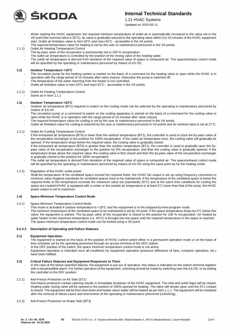
Ev. č. / Ev.-Nr. 3276 S5 ŠKODA AUTO a.s., tř. Václava Klementa 869, Mladá Boleslav II, 293 01 Mladá Boleslav, Czech Republic 22/47Platnost od: 01.02.2020
Internal Technical Standards1.21 HVAC SystemsUpdated on 2020-05-11
- When starting the HVAC equipment, the required minimum temperature of outlet air is automatically increased to the value set in theVD point (the nominal value is 30°C). Its value is gradually reduced to the operating value within 5 to 10 minutes of the HVAC equipmentstart. Outlet air limitation value is min=18°C and max=42°C - accessible in the VA points.
- The required temperature value for heating is set by the user or maintenance personnel in the VA points.1.1.1) Outlet Air Heating Temperature Control
- The by-pass valve of the recuperator is permanently set to 100 % recuperation.- The outlet air temperature is controlled by the position of the mixing valve of the heating water.- The outlet air temperature is derived from deviation of the required value of space or exhausted air. The space/exhaust control mode
will be specified by the operating or maintenance personnel by means of d.b.VD.
1.2) Outdoor Temperature >10°C- The circulation pump for the heating system is started on the basis of a command for the heating valve to open while the HVAC is in
operation with the range period of 10 minutes after valve closure. Otherwise the pump is switched off.- The temperature of the water returning from the heater is not controlled.- Outlet air limitation value is min=18°C and max=42°C - accessible in the VA points.
1.2.1) Outlet Air Heating Temperature Control- Same as in Item 1.1.1
1.3) Outdoor Temperature >23°C- Outdoor air temperature (BT1) required to switch on the cooling mode can be selected by the operating or maintenance personnel by
means of d.b.VA- The circulation pump or a command to switch on the cooling apparatus is started on the basis of a command for the cooling valve to
open while the HVAC is in operation with the range period of 10 minutes after valve closure.- The required temperature value for cooling is set by the user or maintenance personnel in the VA points.- Outlet air limitation value for cooling is selected by the user or maintenance personnel in VA points and its nominal value is set at 17°C.
1.3.1) Outlet Air Cooling Temperature Control- If the exhausted air temperature (BT6) is lower than the outdoor temperature (BT1), the controller is used to close the by-pass valve of
the recuperation exchanger to the position for 100% recuperation. If the outlet air temperature rises, the cooling valve will gradually beopened. If the temperature drops below the required value, the cooling valve is gradually closed.
- If the exhausted air temperature (BT6) is greater than the outdoor temperature (BT1), the controller is used to gradually open the by-pass valve of the recuperation exchanger to the position for 0% recuperation, and then the cooling valve is gradually opened. If thetemperature drops above the required value, the cooling valve is first closed and then the by-pass valve of the recuperation exchangeris gradually closed to the position for 100% recuperation.
- The outlet air temperature is derived from deviation of the required value of space or exhausted air. The space/exhaust control modewill be specified by the operating or maintenance personnel by means of d.b.VD using the same point as for the heating mode.
1.3.2) Regulation of the HVAC outlet power- Shall the temperature of the ventilated space exceed the required limits, the HVAC fan output is set up using frequency convertors to
minimum value (hygiene standards for ventilated spaces have to be maintained). If the temperature of the ventilated space is below therequired limits or the temperature exceeds the maximum value set (standardly 26°C) and at the same time conditions for cooling thespace are created (HVAC is equipped with a cooler or the outside air temperature is at least 5°C lower than that of the area), the HVACpower output is set to maximum.
1.4) Space Minimum Temperature Control Mode
1.4.1) Space Minimum Temperature Control Mode- This mode is activated if outdoor temperature is <18°C and the equipment is in the stopped-by-time-program mode.- The minimum temperature of the ventilated space to be maintained is set by VA point. If the space temperature drops by 2°C below this
value, the equipment is started. The by-pass valve of the recuperator is closed to the position for 100 % recuperation. Air heated bywater heater to the maximum temperature (i.e. 40°C) is brought into the space until the required temperature in the space is reached.
- The space minimum temperature control mode can be locked using a VD point.
5.2.4-2 Description of Operating and Failure Statuses
2.1) Equipment Operation- The equipment is started on the basis of the position of HVAC control switch either in a permanent operation mode or on the basis of
time schedule set by the operating personnel through an access terminal of the DDC station.- In the OFF position of the switch, the space minimum temperature control mode is not active.- Equipment operation is indicated once all conditions for equipment operation (pressure difference of fans, contactor operation, etc.)
have been fulfilled.
2.2) Critical Failure Statuses and Equipment Responses to Them- In the case of the below specified failures, the equipment is put out of operation, this status is indicated on the station terminal together
with a visual/audible alarm. For further operation of the equipment, unlocking should be made by switching over the d.b.VD, or by settingthe controller to the OFF position.
2.2.1) Anti-Freeze Protection on Air Side (ST1)- Anti-freeze protection contact opening results in immediate shutdown of the HVAC equipment. The inlet and outlet flaps will be closed.
Heating water mixing valve will be opened to the position of 100% opened for heating. The valve will remain open until the ST1 contactis closed. The equipment will be then shut down and heater return water will be heated as per item 1.1.1. The equipment will be restartedafter the removal of failure cause and intervention of the operating or maintenance personnel (unlocking).
2.2.2) Anti-Freeze Protection on Water Side (BT3)

Ev. č. / Ev.-Nr. 3276 S5 ŠKODA AUTO a.s., tř. Václava Klementa 869, Mladá Boleslav II, 293 01 Mladá Boleslav, Czech Republic 23/47Platnost od: 01.02.2020
Internal Technical Standards1.21 HVAC SystemsUpdated on 2020-05-11
- If the water temperature drops below 5°C, the HVAC equipment will be immediately put out of operation. The inlet and outlet flaps willbe closed. Heating water mixing valve will be opened to the position of 100% opened for heating. The failure status will be indicated onthe terminal. The valve will remain open until the measured temperature (BT3) rises above 20°C.. The equipment will be then shut downand heater return water will be heated as per item 1.1.1. The equipment will be restarted after the removal of failure cause andintervention of the operating or maintenance personnel (unlocking).
2.2.3) PPK or EFS- If the equipment is provided with the fire alarm system, the equipment must always be put out of operation if the contact of this alarm
system is opened. This status will be indicated on the terminal and the equipment will be locked after the elimination of failure causeand intervention of the operating or maintenance personnel (unlocking).
2.2.4) Fan Failure- If the contacts of fan pressure difference sensors are not closed within 1 minute after starting the equipment, or if the sensor contact
opens during equipment operation, the equipment is locked and put out of operation until the removal of failure cause and interventionof the operating or maintenance personnel (unlocking). The same procedure shall apply in the case when the failure will be indicatedby opening the motor thermal (current) protection, or in case of failed indication of motor contactor operation in the EMI.
2.3) Non-Critical Failure Statuses and Equipment Responses to Them- In the case of the below specified failures, the equipment is in operation, this status is just indicated on the station terminal together with
a visual/audible alarm.
2.3.1) Filter Clogging Failure- If the contact of the differential pressure sensor on filters is opened for 60 seconds, this failure status is indicated on the terminal. The
alarm system will be automatically switched off once the failure cause has been removed.
2.3.2) Pump Failure- In the case of pump failure, this status will be indicated on the terminal. The alarm system will be automatically switched off once the
failure cause has been removed.
2.3.3) Cooling System Failure- In the case of cooling system failure, this status will be indicated on the terminal. The alarm system will be automatically switched off
once the failure cause has been removed.
2.4) Pump Spinning- The system must be equipped with an automatic pump spinning system combined with mixing valve opening to prevent the pump
impeller from drying and getting stuck, and to prevent sediment deposits. This mode can be blocked by means of d.b.VD for the caseof discharging the heating or cooling circuit.
5.2.5 HVAC Equipment - Type 3.1 – High Humidity Areas
5.2.5-1 Control Sequence DescriptionTemperature is controlled based on temperature measurements in the space (BT5) or in the exhaust pipeline (BT6) by controlling the positions ofthe heating valve and cooling valve by means of the plate recuperation heat exchanger, with a limitation to the maximum and minimum output airtemperatures. Application in areas with increased exhaust air humidity.Regulation of HVAC air output in accordance with reaching the values required of regulatory quantities (temperature, humidity, CO2, …)
1.1) Outdoor Temperature <5°C- Circulating pump for the heating system is permanently started regardless of position of valve opening even with HVAC equipment
switched off.- The temperature measured by sensor on heater return water is controlled to temperature set at the VD point (nominal value 15°C).
Temperature control is active even with the HVAC equipment switched off.- When starting the HVAC equipment, the required minimum temperature of outlet air is automatically increased to the value set in the
VD point (the nominal value is 30°C). Its value is gradually reduced to the operating value within 5 to 10 minutes of the HVAC equipmentstart. Outlet air limitation value is min=18°C and max=42°C - accessible in the VA points.
- The required temperature value for heating is set by the user or maintenance personnel in the VA points.
1.1.1) Outlet Air Heating Temperature Control- The by-pass valve of the recuperator is permanently set to 100 % recuperation.- The outlet air temperature is controlled by the position of the mixing valve of the heating water.- The outlet air temperature is derived from deviation of the required value of space or exhausted air. The space/exhaust control mode
will be specified by the operating or maintenance personnel by means of d.b.VD.
1.1.2) Protection Against Frost deposits on Heat Exchanger- If, while the HVAC equipment is in operation, the air humidity sensor (BH4) located in the exhaust air line upstream of the recuperator,
registers relative humidity above 60%, the temperature downstream of the recuperator, as measured by the BT7 sensor, will bemaintained by opening the by-pass valve of the recuperator so that the temperature is at least 5°C.
1.2) Outdoor Temperature >10°C- The circulation pump for the heating system is started on the basis of a command for the heating valve to open while the HVAC is in
operation with the range period of 10 minutes after valve closure. Otherwise the pump is switched off.- The temperature of the water returning from the heater is not controlled.- The temperature downstream of the recuperator is not controlled.

Ev. č. / Ev.-Nr. 3276 S5 ŠKODA AUTO a.s., tř. Václava Klementa 869, Mladá Boleslav II, 293 01 Mladá Boleslav, Czech Republic 24/47Platnost od: 01.02.2020
Internal Technical Standards1.21 HVAC SystemsUpdated on 2020-05-11
- Outlet air limitation value is min=18°C and max=42°C - accessible in the VA points.
1.2.1) Outlet Air Heating Temperature Control- Same as in Item 1.1.1
1.3) Outdoor Temperature >23°C- Outdoor air temperature (BT1) required to switch on the cooling mode can be selected by the operating or maintenance personnel by
means of d.b.VA- The circulation pump or a command to switch on the cooling apparatus is started on the basis of a command for the cooling valve to
open while the HVAC is in operation with the range period of 10 minutes after valve closure.- The required temperature value for cooling is set by the user or maintenance personnel in the VA points.- Outlet air limitation value for cooling is selected by the user or maintenance personnel in VA points and its nominal value is set at 17°C.
1.3.1) Outlet Air Cooling Temperature Control- If the exhausted air temperature (BT6) is lower than the outdoor temperature (BT1), the controller is used to close the by-pass valve of
the recuperation exchanger to the position for 100% recuperation. If the outlet air temperature rises, the cooling valve will gradually beopened. If the temperature drops below the required value, the cooling valve is gradually closed.
- If the exhausted air temperature (BT6) is greater than the outdoor temperature (BT1), the controller is used to gradually open the by-pass valve of the recuperation exchanger to the position for 0% recuperation, and then the cooling valve is gradually opened. If thetemperature drops below the required value, the cooling valve is first closed and then the by-pass valve of the recuperation exchangeris gradually closed to the position for 100% recuperation.
- The outlet air temperature is derived from deviation of the required value of space or exhausted air. The space/exhaust control modewill be specified by the operating or maintenance personnel by means of d.b.VD using the same point as for the heating mode.
1.3.2) Regulation of the HVAC outlet power- Shall the temperature of the ventilated space exceed the required limits, the HVAC fan output is set up using frequency convertors to
minimum value (hygiene standards for ventilated spaces have to be maintained). If the temperature of the ventilated space is below therequired limits or the temperature exceeds the maximum value set (standardly 26°C) and at the same time conditions for cooling thespace are created (HVAC is equipped with a cooler or the outside air temperature is at least 5°C lower than that of the area), the HVACpower output is set to maximum.
1.4) Space Minimum Temperature Control Mode
1.4.1) Space Minimum Temperature Control Mode- This mode is activated if outdoor temperature is <18°C and the equipment is in the stopped-by-time-program mode.- The minimum temperature of the ventilated space to be maintained is set by VA point. If the space temperature drops by 2°C below this
value, the equipment is started. The by-pass valve of the recuperator is closed to the position for 100 % recuperation. Air heated bywater heater to the maximum temperature (i.e. 40°C) is brought into the space until the required temperature in the space is reached.
- The space minimum temperature control mode can be locked using a VD point.
5.2.5-2 Description of Operating and Failure Statuses
2.1) Equipment Operation- The equipment is started on the basis of the position of HVAC control switch either in a permanent operation mode or on the basis of
time schedule set by the operating personnel through an access terminal of the DDC station.- In the OFF position of the switch, the space minimum temperature control mode is not active.- Equipment operation is indicated once all conditions for equipment operation (pressure difference of fans, contactor operation, etc.)
have been fulfilled.
2.2) Critical Failure Statuses and Equipment Responses to Them- In the case of the below specified failures, the equipment is put out of operation, this status is indicated on the station terminal together
with a visual/audible alarm. For further operation of the equipment, unlocking should be made by switching over the d.b.VD, or by settingthe controller to the OFF position.
2.2.1) Anti-Freeze Protection on Air Side (ST1)- Anti-freeze protection contact opening results in immediate shutdown of the HVAC equipment. The inlet and outlet flaps will be closed.
Heating water mixing valve will be opened to the position of 100% opened for heating. The valve will remain open until the ST1 contactis closed. The equipment will be then shut down and heater return water will be heated as per item 1.1.1. The equipment will be restartedafter the removal of failure cause and intervention of the operating or maintenance personnel (unlocking).
2.2.2) Anti-Freeze Protection on Water Side (BT3)- If the water temperature drops below 5°C, the HVAC equipment will be immediately put out of operation. The inlet and outlet flaps will
be closed. Heating water mixing valve will be opened to the position of 100% opened for heating. The failure status will be indicated onthe terminal. The valve will remain open until the measured temperature (BT3) rises above 20°C.. The equipment will be then shut downand heater return water will be heated as per item 1.1.1. The equipment will be restarted after the removal of failure cause andintervention of the operating or maintenance personnel (unlocking).
2.2.3) PPK or EFS- If the equipment is provided with the fire alarm system, the equipment must always be put out of operation if the contact of this alarm
system is opened. This status will be indicated on the terminal and the equipment will be locked after the elimination of failure causeand intervention of the operating or maintenance personnel (unlocking).
2.2.4) Fan Failure- If the contacts of fan pressure difference sensors are not closed within 1 minute after starting the equipment, or if the sensor contact
opens during equipment operation, the equipment is locked and put out of operation until the removal of failure cause and intervention
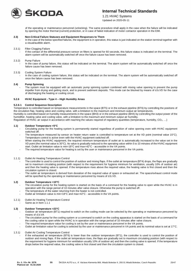
Ev. č. / Ev.-Nr. 3276 S5 ŠKODA AUTO a.s., tř. Václava Klementa 869, Mladá Boleslav II, 293 01 Mladá Boleslav, Czech Republic 25/47Platnost od: 01.02.2020
Internal Technical Standards1.21 HVAC SystemsUpdated on 2020-05-11
of the operating or maintenance personnel (unlocking). The same procedure shall apply in the case when the failure will be indicatedby opening the motor thermal (current) protection, or in case of failed indication of motor contactor operation in the EMI.
2.3) Non-Critical Failure Statuses and Equipment Responses to Them- In the case of the below specified failures, the equipment is in operation, this status is just indicated on the station terminal together with
a visual/audible alarm.
2.3.1) Filter Clogging Failure- If the contact of the differential pressure sensor on filters is opened for 60 seconds, this failure status is indicated on the terminal. The
alarm system will be automatically switched off once the failure cause has been removed.
2.3.2) Pump Failure- In the case of pump failure, this status will be indicated on the terminal. The alarm system will be automatically switched off once the
failure cause has been removed.
2.3.3) Cooling System Failure- In the case of cooling system failure, this status will be indicated on the terminal. The alarm system will be automatically switched off
once the failure cause has been removed.
2.4) Pump Spinning- The system must be equipped with an automatic pump spinning system combined with mixing valve opening to prevent the pump
impeller from drying and getting stuck, and to prevent sediment deposits. This mode can be blocked by means of d.b.VD for the caseof discharging the heating or cooling circuit.
5.2.6 HVAC Equipment - Type 4 – High Humidity Areas
5.2.6-1 Control Sequence DescriptionTemperature is controlled based on temperature measurements in the space (BT5) or in the exhaust pipeline (BT6) by controlling the positions ofthe circulation flap, heating valve and cooling valve, with a limitation to the maximum and minimum output air temperatures.Humidity is controlled based on humidity measurements in the space (BH3) or in the exhaust pipeline (BH4) by controlling the output power of thehumidifier, heating valve and cooling valve, with a limitation to the maximum and minimum output air humidity.Regulation of HVAC air output in accordance with reaching the values required of regulatory quantities (temperature, humidity, CO2, …)
1.1) Outdoor Temperature <5°C- Circulating pump for the heating system is permanently started regardless of position of valve opening even with HVAC equipment
switched off.- The temperature measured by sensor on heater return water is controlled to temperature set at the VD point (nominal value 15°C).
Temperature control is active even with the HVAC equipment switched off.- When starting the HVAC equipment, the required minimum temperature of outlet air is automatically increased to the value set in the
VD point (the nominal value is 30°C). Its value is gradually reduced to the operating value within 5 to 10 minutes of the HVAC equipmentstart. Outlet air limitation value is min=18°C and max=42°C - accessible in the VA points.
- The required temperature value for heating is set by the user or maintenance personnel in the VA points.
1.1.1) Outlet Air Heating Temperature Control- The controller is used to control the position of outdoor and mixing flaps. If the outlet air temperature (BT4) drops, the flaps are gradually
set to maximum circulating position (with respect to the requirement for hygiene minimum for ventilation, usually 10% of outdoor air)and then the heating valve is opened. If the temperature rises above the required value, the heating valve is first closed and then thecirculation system is closed.
- The outlet air temperature is derived from deviation of the required value of space or exhausted air. The space/exhaust control modewill be specified by the operating or maintenance personnel by means of d.b.VD.
1.2) Outdoor Temperature >10°C- The circulation pump for the heating system is started on the basis of a command for the heating valve to open while the HVAC is in
operation with the range period of 10 minutes after valve closure. Otherwise the pump is switched off.- The temperature of the water returning from the heater is not controlled.- Outlet air limitation value is min=18°C and max=42°C - accessible in the VA points.
1.2.1) Outlet Air Heating Temperature Control- Same as in Item 1.1.1
1.3) Outdoor Temperature >23°C- Outdoor air temperature (BT1) required to switch on the cooling mode can be selected by the operating or maintenance personnel by
means of d.b.VA- The circulation pump for the cooling system or a command to switch on the cooling apparatus is started on the basis of a command for
the cooling valve to open while the HVAC is in operation with the range period of 10 minutes after valve closure.- The required temperature value for cooling is set by the user or maintenance personnel in the VA points.- Outlet air limitation value for cooling is selected by the user or maintenance personnel in VA points and its nominal value is set at 17°C.
1.3.1) Outlet Air Cooling Temperature Control- If the exhausted air temperature (BT6) is lower than the outdoor temperature (BT1), the controller is used to control the position of
outdoor and mixing flaps. If the outlet air temperature rises, the flaps are gradually set to maximum circulating position (with respect tothe requirement for hygiene minimum for ventilation usually 10% of outdoor air) and then the cooling valve is opened. If the temperaturedrops below the required value, the cooling valve is first closed and then the circulation system is closed.

Ev. č. / Ev.-Nr. 3276 S5 ŠKODA AUTO a.s., tř. Václava Klementa 869, Mladá Boleslav II, 293 01 Mladá Boleslav, Czech Republic 26/47Platnost od: 01.02.2020
Internal Technical Standards1.21 HVAC SystemsUpdated on 2020-05-11
- If the exhausted air temperature (BT6) is greater than the outdoor temperature (BT1), the controller is used to control just the positionof the cooling mixing valve. The circulation mode is not used.
- The outlet air temperature is derived from deviation of the required value of space or exhausted air. The space/exhaust control modewill be specified by the operating or maintenance personnel by means of d.b.VD using the same point as for the heating mode.
1.3.2) Regulation of the HVAC outlet power- Shall the temperature of the ventilated space exceed the required limits, the HVAC fan output is set up using frequency convertors to
minimum value (hygiene standards for ventilated spaces have to be maintained). If the temperature of the ventilated space is below therequired limits or the temperature exceeds the maximum value set (standardly 26°C) and at the same time conditions for cooling thespace are created (HVAC is equipped with a cooler or the outside air temperature is at least 5°C lower than that of the area), the HVACpower output is set to maximum.
5.2.6-2 Description of Operating and Failure Statuses
2.1) Equipment Operation- The equipment is started on the basis of the position of HVAC control switch either in a permanent operation mode or on the basis of
time schedule set by the operating personnel through an access terminal of the DDC station.- Equipment operation is indicated once all conditions for equipment operation (pressure difference of fans, contactor operation, etc.)
have been fulfilled.
2.2) Critical Failure Statuses and Equipment Responses to Them- In the case of the below specified failures, the equipment is put out of operation, this status is indicated on the station terminal together
with a visual/audible alarm. For further operation of the equipment, unlocking should be made by switching over the d.b.VD, or by settingthe controller to the OFF position.
2.2.1) Anti-Freeze Protection on Air Side (ST1)- Anti-freeze protection contact opening results in immediate shutdown of the HVAC equipment. The inlet and outlet flaps will be closed.
Heating water mixing valve will be opened to the position of 100% opened for heating. The valve will remain open until the ST1 contactis closed. The equipment will then be shut down and heater return water minimum temperature will be maintained as per item 1.1. Theequipment will be restarted after the removal of failure cause and intervention of the operating or maintenance personnel (unlocking).
2.2.1) Anti-Freeze Protection on Water Side (BT3)- If the water temperature drops below 5°C, the HVAC equipment will be immediately put out of operation. Inlet and outlet flaps will be
closed. The heating water mixing valve will be opened to the position of 100% opened for heating. The failure status will be indicatedon the terminal. The valve will remain open until the measured temperature (BT3) rises above 20°C.. The equipment will be then shutdown and heater return water minimum temperature will be maintained as per item 1.1. The equipment will be restarted after the removalof failure cause and intervention of the operating or maintenance personnel (unlocking).
2.2.3) PPK or EFS- If the equipment is provided with the fire alarm system, the equipment must always be put out of operation if the contact of this alarm
system is opened. This status will be indicated on the terminal and the equipment will be locked after the elimination of failure causeand intervention of the operating or maintenance personnel (unlocking).
2.2.4) Fan Failure- If the contacts of fan pressure difference sensors are not closed within 1 minute after starting the equipment, or if the sensor contact
opens during equipment operation, the equipment is locked and put out of operation until the removal of failure cause and interventionof the operating or maintenance personnel (unlocking). The same procedure shall apply in the case when the failure will be indicatedby opening the motor thermal (current) protection, or in case of failed indication of motor contactor operation in the EMI.
2.3) Non-Critical Failure Statuses and Equipment Responses to Them- In the case of the below specified failures, the equipment is in operation, this status is just indicated on the station terminal together
with a visual/audible alarm.
2.3.1) Filter Clogging Failure- If the contact of the differential pressure sensor on filters is opened for 60 seconds, this failure status is indicated on the terminal. The
alarm system will be automatically switched off once the failure cause has been removed.
2.3.2) Pump Failure- In the case of pump failure, this status will be indicated on the terminal. The alarm system will be automatically switched off once the
failure cause has been removed.
2.3.3) Cooling System Failure- In the case of cooling system failure, this status will be indicated on the terminal. The alarm system will be automatically switched off
once the failure cause has been removed.
2.3.4) Humidifier Failure- In the case of humidifier failure, this status will be indicated on the terminal. The alarm system will be automatically switched off once
the failure cause has been removed.
2.4) Pump Spinning- The system must be equipped with an automatic pump spinning system combined with mixing valve opening to prevent the pump
impeller from drying and getting stuck, and to prevent sediment deposits. This mode can be blocked by means of d.b.VD for the caseof discharging the heating or cooling circuit.

Ev. č. / Ev.-Nr. 3276 S5 ŠKODA AUTO a.s., tř. Václava Klementa 869, Mladá Boleslav II, 293 01 Mladá Boleslav, Czech Republic 27/47Platnost od: 01.02.2020
Internal Technical Standards1.21 HVAC SystemsUpdated on 2020-05-11
The recommended closing frequency is once a week.
5.2.7 HVAC Equipment - Type 5 - Technology Exhaust
1) Control Sequence DescriptionControlling the technology exhaust equipment. The exhaust air leading from the equipment is connected to an exhaust pipe of the HVACequipment for space ventilation. The equipment control mechanism is functionally tied with the operation status of the HVAC equipment for spaceventilation (e.g. by means of C-Bus, LON communication or a contact signalling the operation or failure of the system). Servo-drives in the by-pass and the main pipelines must be equipped with a spring which opens the valves if there is a power outage of the technological exhaust,interrupted communication (information on the operation of the HVAC equipment for ventilation) or if there is a power outage or control failure ofthe technology exhaust equipment.
1.1) Main HVAC = Operation – Tech. Exhaust = Operation- The technology exhaust equipment fan is on- The by-pass valve is closed- The valve in the main pipeline is open
1.2) Main HVAC = Operation – Tech. Exhaust = OFF- The technology exhaust equipment fan is off- The by-pass valve is open- The valve in the main pipeline is open
1.3) Main HVAC = OFF – Tech. Exhaust = ON- The technology exhaust equipment fan is on- The by-pass valve is open- The valve in the main pipeline is closed
2) Description of Operating and Failure Statuses
2.1) Equipment Operation- The equipment is activated by the position of the switch controlling the technology exhaust.- A failure of the equipment is reported by a signal light on the controller in the room.
2.2) Critical Failure Statuses and Equipment Responses to Them- In the case of the below specified failures, the equipment is put out of operation, this status is indicated on the station terminal together
with a visual alarm. For further operation of the equipment, unlocking should be performed by switching the d.b.VD or by setting thecontroller in the distribution board to the OFF position.
2.2.1) Fan Failure- If the fan pressure difference sensor contacts are not closed within 1 minute after starting the equipment, or if the sensor contact opens
during equipment operation, the equipment is locked and put out of operation until the removal of failure cause and intervention of theoperating or maintenance personnel (unlocking). The same procedure shall apply in the case when the failure will be indicated byopening the motor thermal (current) protection, or in case of failed indication of motor contactor operation in the EMI.
2.3) Non-Critical Failure Statuses and Equipment Responses to Them- In the case of the below specified failures, the equipment is in operation, this status is just indicated on the station terminal together with
a visual/audible alarm.
2.3.1) Filter Clogging Failure- - If the contact of the differential pressure sensor on filters is opened for 60 seconds, this failure status is indicated on the terminal. The
alarm system will be automatically switched off once the failure cause has been removed.
6. Installing M&R DevicesInstallation of the M&R system must respect the following principles:
1. Cable routes should be made of steel cable ducts covered with lids after finishing the installation. These lids should be strapped to theducts to prevent their loosening. The strapping should be performed both in the horizontal and the vertical direction. The cable routesshould be made with straight ducts and shaped pieces! In the main route, the shaped pieces of the external bend should be fortifiedwith riveted metal sheets filling the space in the bend.
2. Supports and bearing frames should be dimensioned so that the cable route is sufficiently supported and the ducts do not sag.3. Free bushings on the distribution board should be fitted with seals! Cables should be sealed in the bushings.4. Ends of the ducts where the cables pass and cutouts for large amounts of cables should be equipped with a rubber band with steel
reinforcement designed for this purpose. Passages of one or two cables will be conducted through GEWISS rubber grommets for whichholes will be milled in the cable duct.
5. Passages of one or two cables into the HVAC units will be conducted through the GEWISS rubber grommets mounted on both sides.6. For reinforced plastic conduits and pipes, shaped pieces (elbows, couplers, covers, etc.) and a sufficient number of fasteners should
be used. At least two fasteners should be used for each straight section. The route should be sheltered along its entire length. Themaximum allowed length of unsheltered section at the end of the route in areas entering the device and in branches is 15 cm. Theseunsheltered sections may only be used if the entire route cannot be sheltered!
7. Cables inside the HVAC unit should be sheltered in flexible metal pipes attached to fasteners; it is forbidden to use plastic tubes,fasteners and boxes.
8. Each component of the field instrumentation must be machine described in agreement with project documentation or documentation ofthe real condition (motors, servo-drives, sensors, etc.)! Differential manostats, anti-freezing thermostat and the frequency convertermust be equipped with labels written by a machine which contain the adjusted values.

Ev. č. / Ev.-Nr. 3276 S5 ŠKODA AUTO a.s., tř. Václava Klementa 869, Mladá Boleslav II, 293 01 Mladá Boleslav, Czech Republic 28/47Platnost od: 01.02.2020
Internal Technical Standards1.21 HVAC SystemsUpdated on 2020-05-11
9. In the distribution board, each outgoing cable must be equipped with a machine-written label with the following data: type of the cable,from where, to where, description of the device in which it is terminated - e.g. indoor temperature sensor. These labels must be placedon the other end as well - for peripheries.
10. Shielding of the cables will be terminated at the terminals. Green spaghetti insulation must be pulled over the cable from the strippedsection to the terminal along the entire length of the shielding to protect the cables.
11. The M&R switchboard must be fitted with a C-class biased differential protection produced by DEHN, SALTEK or BETTERMANN.12. Each HVAC unit must be fitted with a service switch. This switch should be connected to the motor contactors (in low-input motors
directly to the power supply circuit); it will prevent starting the HVAC unit during service operations.13. Heavy-current cables and cables for M&R devices must be separated in independent routes.14. Heavy-current cables and the M&R cables will be separated in the switchboard, too. Special attention should be paid to separation of
cables when the SELV, PELV protection is used.15. Each M&R switchboard or each field of assembled switchboards must be fitted with a light that can be switched on in the distribution
board.
7. Content of Documentation Handed Over During Acceptance- As-built documentation in three copies including a list of operations and a cable chart, all in one copy on a CD.- A full-colour A3-size regulation chart laminated in a self-adhesive foil.- M&R system operation manual (SW description)- A list of protecting elements in the distribution boards (an identical list will be glued on the inside of the distribution board door in a
transparent folder)- A list of adjusted values (differential manostats, safety thermostat, heat protections, etc.) - identical values will be included in a machine-
written label glued directly on the particular periphery.- A data point identification sheet- A list of SW on a CD- A SW back-up on a CD

Ev. č. / Ev.-Nr. 3276 S5 ŠKODA AUTO a.s., tř. Václava Klementa 869, Mladá Boleslav II, 293 01 Mladá Boleslav, Czech Republic 29/47Platnost od: 01.02.2020
Internal Technical Standards1.21 HVAC SystemsUpdated on 2020-05-11
7.1 Specimen Full-Color Regulation Chart
7.2 Data Point Identification Sheet
Refer to a separate annex.

Ev. č. / Ev.-Nr. 3276 S5 ŠKODA AUTO a.s., tř. Václava Klementa 869, Mladá Boleslav II, 293 01 Mladá Boleslav, Czech Republic 30/47Platnost od: 01.02.2020
Internal Technical Standards1.21 HVAC SystemsUpdated on 2020-05-11
B. Machinery Section
1. Supplier-Customer Relations
1.1 BidWhen preparing its bid, the contractor is required to verify on site the actual condition of the requisite structural dimensions, installation openings,transport routes, etc. A precise schedule of work must be discussed with the PPB departments. Any changes made by the contractor betweenthe bid submission date and the final status do not justify any unit price increase. The submitted documentation must contain drawings ofequipment implementation, functional chart with a description of the device function and other necessary technical data including animplementation plan.The contractor shall preferentially offer and propose in the design plans the equipment and components listed in Annex 1!Components produced by other manufacturers or non-standard models may only be used with a consent from the ŠE-TS (Ško-Energo– TS department, hereinafter referred to as ŠE-TS)!
1.2 Planning DocumentationThe planner shall submit the technical documentation in the required extent by the deadline stipulated in the contract. All planning particulars arebased on valid regulations - Act No. 183/2006 Coll., the Building Act, Decree No. 499/2006 Coll., on documentation of construction sites, thePerformance and Fee Rules. The contractor shall submit the stipulated number of copies in a printed form and one version in a digital form inaccordance with the ITS 1.01.The planning documentation will be performed in line with technical drawing principles. The subject of the solution will be unambiguouslydetermined by the thickness and type of lines in the drawings. The drawings must be transparent and made in a scale allowing easy reading fromthe drawings.At the blow outlets air flow measurements will be carried out.
1.3 As-Built DocumentationThe scope and contents of the as-built documentation is determined by Decree No. 499/2006 Coll.The HVAC equipment supplier shall submit technical documentation reflecting the actual status in volume specified in the point 1.4.The documentation must include the following in particular:
- as-built drawings precisely showing the position of HVAC pipeline routes- drawings of technology parts with relevant cross-section views- charts describing the equipment functions and source data for calculations
Drawings of the equipment and pipe routes must be prepared according to the valid ČSN standards.
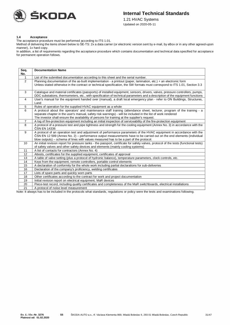
Ev. č. / Ev.-Nr. 3276 S5 ŠKODA AUTO a.s., tř. Václava Klementa 869, Mladá Boleslav II, 293 01 Mladá Boleslav, Czech Republic 31/47Platnost od: 01.02.2020
Internal Technical Standards1.21 HVAC SystemsUpdated on 2020-05-11
1.4 AcceptanceThe acceptance procedure must be performed according to ITS 1.01.Method of delivering the items shown below to ŠE-TS: 2x a data carrier (or electronic version sent by e-mail, by eBox or in any other agreed-uponmanner), 1x hard copy.In addition, a list of requirements regarding the acceptance procedure which contains documentation and technical data specified for acceptancefor permanent operation follows.
Seq.No.
Documentation Name
1 List of the submitted documentation according to this sheet and the serial number.2 Planning documentation of the as-built implementation - a printout (paper, lamination, etc.) + an electronic form
Unless stated otherwise in the contract or technical specification, the SW formats must correspond to ITS 1.01, Section 3.3
3 Catalogue and material certificates (passports) of installed equipment, sensors, drivers, valves, pressure controllers, pumps,DDC substations, thermometers, etc., with specification of technical parameters and a description of the equipment functions
4 User's manual for the equipment handed over (manual), a draft local emergency plan - refer to ON Buildings, Structures,Land
5 Rules of operation for the supplied HVAC equipment as a whole6 A protocol about the operators' and maintenance staff training (attendance sheet, lecturer, program of the training - a
separate chapter in the user's manual, safety risk warnings) - will be included in the list of work renderedThe investor shall ensure the availability of persons for training at the supplier's request.
7 A log of fire-protection equipment including an initial inspection of serviceability of the fire-protection equipment8 A protocol of a pressure test and pipe tightness and strength for the cooling equipment (Annex No. 3) in accordance with the
ČSN EN 143369 A protocol of an operation test and adjustment of performance parameters of the HVAC equipment in accordance with the
ČSN EN 12 599 (Annex No. 2) – performance output measurements have to be carried out on the end elements (individualblow outputs) – schema of lines with values measured has to be a part of the protocol.
10 An initial revision report for pressure tanks - the passport, certificate for safety valves, protocol of the tests (functional tests)of safety valves and other safety devices and elements (mainly cooling systems)
11 A list of contacts for contractors (Annex No. 4)12 Attests, certificates for the supplied equipment, certificates of approval13 A table of valve setting (plus a protocol of hydronic balance), temperature parameters, clock controls, etc.14 Keys from the equipment, remote controllers, portable control elements15 A declaration of conformity for the whole work including partial declarations for sub-deliveries16 Declaration of the company's proficiency, welding certificates17 Lists of spare parts and quickly worn parts18 Other certificates according to the contract for work and project documentation19 Initial revision report on electrical equipment, MaR devices20 Piece-test record, including quality certificates and completeness of the MaR switchboards, electrical installations21 A protocol of noise level measurement
Note: It always has to be included in the protocols what standards, regulations or policy were the tests and examinations following.

Ev. č. / Ev.-Nr. 3276 S5 ŠKODA AUTO a.s., tř. Václava Klementa 869, Mladá Boleslav II, 293 01 Mladá Boleslav, Czech Republic 32/47Platnost od: 01.02.2020
Internal Technical Standards1.21 HVAC SystemsUpdated on 2020-05-11
2. Standards, Regulations, Guidelines, LegislationAll the HVAC equipment must comply with requirements of the valid standards and regulations regarding occupational safety and requirementsof economical and ecological operation.
GR 201/2012 Coll. Air Protection ActGR 361/2007 Coll. Government regulation regarding protection against noise and vibrationsDecree No. 137/2004 Coll. Decree on hygienic requirements regarding catering and principles of personal and operational hygiene
during epidemiologically serious activitiesDecree No. 246/2001 Coll.
Act 73/2012 Coll.EP and Council Reg. No.1005/2009EP and Council Reg. No.517/2014
Decree No. 279/2009 Coll.
Decree that determines requirements for fire safety and performance of state fire supervision (Fire PreventionDecree)Act on substances that damage the ozone layer and on fluorinated greenhouse gasesEuropean Parliament and Council Regulation (EC) on substances that damage the ozone layerEuropean Parliament and Council Regulation (EC) on fluorinated greenhouse gases and on cancellingRegulation (EC) No. 842/2006
Decree on preventing emissions of regulated substances and fluorinated greenhouse gasesČSN 01 3452 Technical drawings - Installations - Heating and coolingČSN 12 0017 Methods of measuring and evaluating noise of HVAC equipment. General specifications.ČSN 12 2002 Ventilators. General safety requirements.ČSN 12 3061 Heating, ventilation and air-conditioning systems. Ventilators. Measurement regulations.ČSN 12 4000 Heating, ventilation and air-conditioning systems. Separators and filters. Common provisions.ČSN EN ISO 16890 1-4 Air filters for general ventilationČSN 12 5606 Steam air heaters. Measurement and assessment.ČSN 12 7001 Heating, ventilation and air-conditioning systems. Air-conditioning units. Series of basic parameters.ČSN 12 7040 Heating, ventilation and air-conditioning systems. Exhaustion of pollutants from machines and technical
equipment. General specifications.ČSN EN 1505 Ventilation of buildings - Metal-sheet pipeline and right-angle cross-section fittings - dimensionsČSN EN 1506 Ventilation of buildings - Metal-sheet pipeline and circular cross-section fittings - dimensionsČSN EN 1507 Ventilation of buildings - Metal-sheet pipeline and right-angle cross-section fittings - Requirements for rigidity
and tightnessČSN EN 12 220 Ventilation of buildings - Pipelines - Dimensions of circular flanges for general ventilationČSN EN 12 236 Ventilation of buildings - Brackets and pipeline seating - Requirements for rigidityČSN EN 12 237ČSN EN 12 599
Ventilation of buildings - Pipeline - Rigidity and tightness of metal-sheet pipeline of circular cross-sectionVentilation of buildings - Ventilation for buildings - Test procedures and measurement methods to hand over airconditioning and ventilation systems
ČSN EN 13 180 Ventilation of buildings - Pipeline - Dimensions and mechanical requirements for flexible pipesČSN EN 13 403 Ventilation of buildings - Non-metallic piping - HVAC piping made of insulating boards.ČSN EN 16 798-3 Energy efficiency of buildings - Ventilation of non-residential buildings - Basic requirements for ventilating and
air-conditioning systemsČSN EN 378 1-4 Cooling equipment and heat pumps - Safety and environmental requirementsČSN EN 16 798-17
ČSN EN 14 336
Energy performance of buildings - Ventilation for buildings - Part 17: Guidelines for inspection of ventilation andair conditioning systemsHeating systems in buildings - Installation and commissioning of water based heating systems
ČSN 73 0804 Fire safety of buildings - Manufacturing facilitiesČSN 73 0872 Fire safety of buildings. Protection of buildings against fire spreading through HVAC systemsČSN 73 0540 1-4 Heat protection of buildings
3. General Technical RegulationsThe HVAC equipment must be designed so that it satisfies all the required functions, air performance, temperatures and humidity parameters ofthe air and other requirements for this equipment. All components of the equipment must be designed to ensure a perfect operation, servicing andrepairs.All HVAC units have to be supplied as silicon-free version.Summer temperature for calculations to be proposed as te ≥ 32°C. Exterior cooling machines to be designed for 35°C.
3.1 General Requirements for HVAC System Design
3.1.1 Suction of Air and Exhaust of Outlet AirSuction of outdoor air must be implemented so that air is sucked from a hygienically clean environment. Suction apertures must be protectedagainst access of impurities, birds, snow and other foreign objects (e.g. netting, mesh).Exhaust of the outlet air must not bother or endanger the surrounding area in any way, and the applicable legal and hygienic regulations must beobserved. The exhaust aperture must be equipped with a shielding from wind, rain, etc. and the exhaust pipe must be directed above the roof ofthe building if possible. The exhaust current must never affect the suction of fresh air by any of the HVAC units.
3.1.2 Drive UnitA suitable model of ventilator driven by an electric motor should be used as a drive unit. The ventilator should ensure optimal air performance atthe minimum efficiency of 75% with regard to pressure losses and noise level of the equipment.Design the systems with ventilators directly coupled with an electric motor.For air flow V ≥ 3,000 m3/hr flow measurement on the fan has to be multi-point.
3.1.3 Air Filtration

Ev. č. / Ev.-Nr. 3276 S5 ŠKODA AUTO a.s., tř. Václava Klementa 869, Mladá Boleslav II, 293 01 Mladá Boleslav, Czech Republic 33/47Platnost od: 01.02.2020
Internal Technical Standards1.21 HVAC SystemsUpdated on 2020-05-11
Air that is treated by heat and is brought into the room must always be filtered. The filter type always depends on the air quality requirements.Freely accessible and easily removable filters which allow regular maintenance and cleaning should always be used. If the unit has its chamberspositioned on top of each other, it is necessary to ensure access to the top chambers (e.g. mobile steps with a platform, etc.).Suction equipment which sucks technological impurities must be equipped with efficient filtrating or separating units. Waste disposal proceduremust always be planned.HVAC units filtration chambers have to be equipped with pressure U-manometres labelled with the filter type and start and end pressure loss.
3.1.3.1 Technical ImplementationBasic requirements and joint resolutions for air filters are specified by ČSN EN ISO 16890.The use of a specific filter type is determined by a requirement for environment purity, spatial requirements and purity grade requirements withregard to the general separability. Tightness between the filter frame and the filter insert must correspond to the respective quality grade of theused filtration media. The filter insert must be inserted and attached in a way which prevents release of captured dust during vibrations and mustbe easily replaceable (slides, U-profiles). Hooks or springs should not be used if possible (minimizing of fouling the interior of the unit during filterreplacement). The general design of the filter and the inlet equipment to the filter cloth must ensure even supply of air throughout the entire profile..All filters should be equipped with directly displaying U-manometers and a label specifying the filter type and its initial and final pressure loss.
3.1.4 Heat Exchangers
3.1.4.1 ConnectionSleeves for the inlet and return pipe must be positioned on the highest and the lowest point of the exchanger for proper draining and deaeration.If such an arrangement is not possible, deaeration valves must be positioned in the highest point of the exchanger and a draining valve in thelowest point so that the water can be drained without any difficulty.Hot-water heaters must be connected to the piping of heating water by means of a flange connector. Connecting lines of hot water heaters andcoolers in the DN40 dimension and bigger have to be in flange joints.
3.1.4.2 Electrical HeatingElectric heaters can only be used in exceptional, economically justified cases and must be approved by the ŠE-TS department. Otherwise, heatingby warm and hot heating water is preferred.
3.1.4.3 Type LabelsEach heat exchanger must be equipped with a type label in a well visible and accessible area. The label must contain the following information:
- trade-mark or the name and the manufacturer's registered office- country of origin- type- year of production- serial number- weight- max. operation pressure or overpressure- parameters
3.1.4.4 Exchanger Material and Wave HeightPreference should be given to steel exchangers instead of copper ones. The wall thickness of a copper exchanger must be at least 0.8 mm.Wave and rib height for heater, cooler, and rotation exchanger have to be in the range between 2-2.5 mm.
3.1.4.5 Air HeatersSpecified limit values:
- operational overpressure pmax = 21bar = 2.1MPa- compression stage min. PN16 and on heating aggregates PN6 of the same pressure level or higher- pressure loss on the water side at the maximum flow of the heating medium pmin = 1kPa, pmax = 20kPa- pressure loss on the air side of all heaters in the series pmax = 200Pa- speed of air flow adjusted for the clear profile of the heater wmax = 6m/s- heating water temperature tmax = 130°C
3.1.4.6 Air CoolersRules for designing coolers are similar to the heater design rules. Pure non-aggressive water should be used as a coolant.Specified limit values:
- operational overpressure pmax = 10bar = 1MPa- compression stage PN10- pressure loss on the water side at the maximum flow of the cooling medium pmin = 1kPa, pmax = 30kPa- pressure loss on the air side of all coolers in the series pmax = 300Pa- speed of air flow adjusted for the clear profile of the cooler wmax = 4m/s- a drop eliminator must be fitted for speeds exceeding 3m/s
3.1.4.7 Recuperation Heat Exchangers (RHE)When building new buildings or reconstructing existing ones in accordance with the EU ecodesign legislation, HVAC units should be suppliedtogether with heat recuperation equipment (plate, rotating exchangers, heat tubes). However, it is always necessary to plan energy-efficientequipment in accordance with Decree No. 148/2007 Coll. (Decree on Energy Efficiency of Buildings).When financially justified, it is recommended that HVAC units containing the RHE units should be equipped with by-passes to reduce powerconsumption in the heating off-season.HVAC units equipped with a ZZT rotational exchanger should be designed in a way that uses the full flow profile of the exchanger.

Ev. č. / Ev.-Nr. 3276 S5 ŠKODA AUTO a.s., tř. Václava Klementa 869, Mladá Boleslav II, 293 01 Mladá Boleslav, Czech Republic 34/47Platnost od: 01.02.2020
Internal Technical Standards1.21 HVAC SystemsUpdated on 2020-05-11
3.1.5 Ventilators
3.1.5.1 BearingsThe service life of bearings must be at least 39,000 hours at maximum load. With lubricated bearings, the period between lubrications must be atleast 4,000 hours.
3.1.5.2 Surface ProtectionAll ventilator components exposed to corrosion risks, including the base frame, must be coated with a primer and upper paint coating. Paintscontaining metallic pigments may not be used for ventilators designed for use in explosion and fire prone environments.
3.1.5.3 Drive MotorsOnly air-cooled standardized motors with a shoulder or a flange may be used. The nominal output of the drive motor must be selected to accountfor the safety surcharge to the output of the ventilator's drive. Electromotor protection settings are determined by ITS M&R for the HVAC equipment.It is necessary to use electric motors with an increased efficiency in line with EU Commission Regulation No. 640/2009.Electric motors must be fitted with revolution frequency control. Revolutions must be controlled from the required quantity - the standard is the airvolume flow; it is not admissible that the motor revolutions be simply set to a constant speed.In HVAC units placed externally and internally in areas with high contamination of air (such as body shop, smeltery, engine assembly shop, etc.)have to have the frequency convertor placed in a way that it is protected from sunlight and contamination. In case of doubts, please turn to ŠE-TS.In ventilated rooms where the primary pollutant is CO2 (meeting rooms, conference halls etc.), the air flow control should be designed startingfrom the CO2 sensor. Maximum CO2 concentration permissible is 1200 ppm.
3.1.5.4 Type PlatesEach ventilator must be equipped with a metal-sheet type plate riveted or bolted to the body at a well visible and accessible point.The plate must contain the following information:
- manufacturer- type and size- volume flow- density- total pressure- input power- rated rpm- weight- serial number- year of production
The impeller rotation direction must be marked with an arrow on the ventilator.If the ventilator is equipped with a revision cap, it must include a warning sign reading: CAUTION! THE VENTILATOR MUST BE TURNED OFFAND THE IMPELLER MUST STOP TURNING BEFORE OPENING.
3.1.5.5 Connecting, Seating and Technical Implementation of VentilatorsThe ventilator flanges should be fitted with absorbing inserts with steel flanges and a textile lining to reduce the transfer of vibrations from theventilator to the suction and exhaust piping.The ventilator frame should be seated on the base frame via vibration separators.When ventilators driven by belt are used, the belt must be equipped with a cover. All rotating components must be equipped with protectivefeatures to prevent a person from touching them.If air containing liquids is to be sucked, the lowest area of the spiral chamber must be equipped with a drain sleeve.Roof ventilators must be made of non-corrosive materials and coated with a quality paint. The outer head must be designed to protect the ventilatedarea from weather influences. All HVAC units that suck air form the outdoor environment or exhaust air into the outdoor environment must beequipped with a shutting overpressure flap to eliminate access of cold air into the interior.
3.1.6 Forbidden SubstancesUsage of silicon and asbestos materials or other substances that damage surfaces of materials (lacquers etc.) is forbidden at ŠKODA AUTO a.s.
3.1.7 Signalling of Flooded Machine Room of HVAC EquipmentClosing electric valves coupled with a sensor (refer to the HVAC M&R) must be installed at the inlet and return pipes of the water heating orcooling register.
3.1.8 Speed Within Unit, External Pressure LossThe air flow speed inside the unit may not exceed 3 m/s.Where technically possible, external pressure loss in the HVAC system should be designed for maximum 400 Pa in order to minimize powerconsumption.
3.1.9 Room Ventilation ConceptA single HVAC unit may be used to ventilate multiple rooms only if the rooms have the same temperature mode, same type of use and similarheat gains and loads. Otherwise, a separate ventilation unit must be used for each of the rooms.
3.2 Air Ducts
3.2.1 General RequirementsAir ducts should satisfy requirements of economical operation of the whole equipment in terms of their shapes, dimensions and materials used.Air speed in the pipeline is to be selected with respect to the required air flow, economy with regard to the ventilator pressure, noise generated byair flow in the piping sections and the HVAC elements and, in the technological exhaust, the nature of the exhausted impurities.

Ev. č. / Ev.-Nr. 3276 S5 ŠKODA AUTO a.s., tř. Václava Klementa 869, Mladá Boleslav II, 293 01 Mladá Boleslav, Czech Republic 35/47Platnost od: 01.02.2020
Internal Technical Standards1.21 HVAC SystemsUpdated on 2020-05-11
Routing of the HVAC pipeline - effort should be made not to install them below skylights, windows and in other areas where it would reduce thedaylight coming through.In areas where the air mass is exhausted together with substances prone to condensing, separating and running along the inner walls of theHVAC pipeline, the lowest point should be equipped with a draining and catching system. It is also necessary to ensure such tightness of the pipeconnectors that eliminates dripping of these substances in the joints or connecting points. A solution for disposing of these captured substancesmust be included in the design plan.Pipes bringing in cool air (outdoor in winter, cooled in summer) must be equipped with thermal insulation to eliminate condensation.
3.2.2 Metal-Sheet Tubes and Shaped PiecesThe HVAC pipeline is made of galvanized or black sheet metal in a square or circular cross-section. Dimensions of the pipeline, its rigidity andtightness are determined by the applicable EN standards.
3.2.3 Piping Brackets, Anchoring MaterialAll brackets, support frames, pillars, etc. must be selected with regard to the static and dynamic carrying-capacity requirements. A static calculationof the suspension must be submitted upon request. The piping should be suspended in a way that allows individual sections to be removed. Thedistance between the brackets should be determined with regard to the minimum sag of the pipeline; however, not greater than 3 m. Attachmentand suspension of the pipeline onto the existing equipment must be consulted with the relevant department of ŠKODA AUTO a.s.Systems commonly available on the market, such as angle bars, collars, ropes, bars, threaded pipes, bolts and steel expanding plugs may beused for suspending the pipeline. The pipeline may be anchored in peripheral walls of buildings or suspended from roof frames in the halls androom ceilings by means of steel ropes or wall plugs. Exhaust pipes above the roof must be anchored in 3 directions. Anchoring ropes must beequipped with tightening elements and the ends must be attached with rope braces. Anchoring in the roof is to be handled by the constructionstaff. Attachment into building structures must be performed via a flexible rubber material. The HVAC pipeline must be separated from thesuspension material by means of a flexible cushioning material.A list of the suspension elements must be included in the planning documentation (a list of work performed).
3.2.4 Pipeline CoatingAll HVAC pipes that are made of sheet metal and are exposed to weather influences must be coated with weather-resistant protective paints orprotective surface materials (e.g. galvanizing). If chemically aggressive substances are to be exhausted, even the inner walls of the pipes mustbe coated.
3.2.5 Revision Cases and Doors, Inspection AperturesIf air containing large numbers of solid particles is to be exhausted, the pipeline must be equipped with inspection apertures or holes with revisioncaps, doors or lids for inspection of fouling and the cleaning of the pipeline. These are to be positioned 6m apart at well accessible places (thismainly applies to foundries, welding halls and mechanical halls with a higher concentration of aerosols).
3.2.6 Roof PassagesPassages of the HVAC piping through the roof are to be handled directly on site during pipeline assembly and installation and upon consultationwith ŠKODA AUTO a.s. The passage must be carefully sealed.
3.2.7 Plastic Pipes, Flexible HosesIn special cases when chemically and corrosively aggressive substances are to be exhausted, plastic pipes may be used.In cases where operational reasons do not allow usage of fixed connection between piping sections or due to the variability of distribution elements,flexible hoses may be used. The length, however, must be limited to the shortest possible extent.
3.2.8 Terminal and Regulating ElementsTerminal elements of the equipment, such as outlets, anemostats, grilles, blinds, heads, roofs and regulating elements, such as control and throttlevalves and slide-valves, should be selected with regard to a correct function of the entire equipment, mainly with regard to regulating the quantity,flow direction and air flow speed. Control elements in the pipeline must be easily accessible and the CLOSED - OPEN position must be marked.The operational position must be marked with a non-washable paint (the valve position after setting the air flow).In production halls, outlets should be planned with a motor-driven function to change from the summer to the winter mode and vice versa. Thissetting will be derived from the ratio of supply air temperature to the temperature of the ventilated area: if the area temperature is higher than thesupply air temperature, the outlet will be set to the cooling mode, whereas area temperature lower than the supply air temperature will cause theoutlet to be set to the heating mode, with the air blown perpendicularly downward.
Operating Controllable OutletsEvery outlet allowing the air distribution to be changed will be mounted with a servo drive (ref. type LM230A - BELIMO) – the Nm value dependson the outlet size
The servo drive will be connected to a 230V power supply. Power will be brought to the outlets from the M&R distribution board corresponding tothe HVAC equipment controlled! The number of cables going out from the M&R distribution board and their dimensions are determined by thenumber of air outlets and their distance from the distribution board.
3.2.9 Indicating Flow DirectionsAir ducts must be marked with a colour arrow showing the direction of the air mass flow according to the relevant key, which marks the type ofthe conveyed air mass.
Green arrow - supply of fresh ventilation airRed arrow - supply of treated air into the ventilated roomDark blue arrow - exhaust air from the ventilated roomBlack arrow - exhaust of deteriorated air into the atmosphere

Ev. č. / Ev.-Nr. 3276 S5 ŠKODA AUTO a.s., tř. Václava Klementa 869, Mladá Boleslav II, 293 01 Mladá Boleslav, Czech Republic 36/47Platnost od: 01.02.2020
Internal Technical Standards1.21 HVAC SystemsUpdated on 2020-05-11
3.2.10 Noise SilencersIf the ventilator does not meet required noise level requirements, it should be equipped with effective silencers.The silencers must be able to work under the following conditions:
- dusty and wet environment- Temperatures from -12 to 60°C- The material used must be non-flammable and wear resistant for air flow speeds up to 20m/s- The silencer must be equipped with a protective steel grill to eliminate falling of the silencing material on the air-flow side- The run-in edge of in-pipe silencers must be inclined or rounded, it may not be flat.
3.2.11 Fire PrecautionsSpecific fire precautions associated with the HVAC equipment must be consulted with the fire prevention department of ŠKODA AUTO a.s. in linewith the required fire safety class. Specific fire sections must be separated by fire dampers in the pipeline. In areas with a higher risk of fire (e.g.paint shops, run-in cylinders, first start, engine test rooms etc.), the pipeline must be equipped with open fog jets.Fire dampers must be freely accessible for revisions and servicingA log of fire dampers and the initial revision must be submitted as part of the acceptance procedure. The revision must meet the requirementsdefined by Regulation 246/2001 Coll. and ČSN 73 0872.A revision aperture must additionally be made on the pipe to allow the inspection of TROX fire dampers.3.2.12 List of Work Performed, BudgetSheet metal pipes and troughs, assembly sections and accessories must be supplied and installed together with cutouts, sleeves, flanges, frames,fixings, sealing material, welds, suspending and supporting frames and control elements. The quantity of pipes (equipment) must be in relation tothe surface area of the piping (m2) with regard to the relevant group, thickness of the sheets, materials and connecting flanges.
3.3 Implementation of HVAC Units and HVAC Machine Room
3.3.1 Unit Chamber LockingDoors of the HVAC units must be equipped with a lock, better still with a door-handle with a lock. If the manufacturer does not deliver door-handleswith locks (small units), the door may only be equipped with a lock; in addition, the door must be equipped with a handrail. If the technical designdoes not allow fitting a door-handle with a lock or a lock, the method of locking must be consulted with the ŠE-TS department.Each supplier of HVAC units must use one standardized key for his products.
3.3.2 Sight Glasses, Chamber Lighting and Lighting Around UnitsHVAC units with an air flow of 10,000 m3/h or higher must be equipped with sight-glasses in all doors and lighting in all chambers. The unit mustbe equipped with complete lighting of the chambers with the connection cables conducted into the distribution board of the unit. A switch forturning on and off the lighting will be installed and connected within the wiring operation.The service area of stand-alone units outside the machine-room (e.g. on the object's roof or steel frames) must be sufficiently lit with regard to thevalid legislative for the given nature of the work.For each HVAC unit, there must be one 32A/400V socket and min. 1 16A/230V socket available.
3.3.3 Unit and Tank CleaningFor a block- and modular-design HVAC unit, free chambers must be fitted before and behind both exchangers to facilitate cleaning of both rotaryand heat exchanger (cooler and heater). The free chamber has to be wide enough (min. 50 cm) to allow the maintenance worker to wash theexchanger freely and also to check the anti-freeze protection. Exceptions in cleaning exchangers in case of clean areas ventilation will benegotiated by the supplier with the ŠE-TS.Every HVAC unit above 10,000 m3/hr with wet clean must be equipped with retaining tanks under each of the chambers (to be included in theHVAC equipment) and a pipe connection to a collector sewage pipe terminated with a stop valve. Here, the HVAC unit is connected to the stopvalve and the polluted water is drained.Units positioned above areas that might be damaged in case of heating water failure in the unit must be fitted with a retaining container (galvanized,stainless steel, etc.) which would retain and conduct all water into the sewer system (the container must be connected to the sewer system). Thetank must cover the entire layout of the unit.The cleaning method must be described in the rules of operation. The cleaning agent connecting point must be available within a reasonabledistance of the HVAC unit (max. 50 m).
3.3.4 Water NodeThe water node must comply with the connection and implementation requirements according to ITS 6.22 Heating Equipment.The water node should be positioned in the interior area of the building as close to the unit as possible; however, it must be freely accessible forservicing. Its position above the ceiling is only possible if it is approved by the ŠE-TS department.. In such a case, there must be a tank placedunder the node to capture any leaks in order to prevent damage to the suspended ceiling.If the water node is to be installed outdoors, then it should preferably be placed in a separate case next to the HVAC unit. This solution will makeit possible to freely access the node and perform repairs if required. The node is not exposed to such a heat load from the unit heater and doesnot represent an inserted resistance on the air flow route through the unit.If the node cannot be placed inside the interior area of the building, it may be positioned in a free chamber of the unit (designed only for thisparticular node). Pipe passages into the free chamber of the unit must be carefully sealed. The piping and the fittings inside the chamber must besufficiently thermally insulated because of the M&R elements' and electrical elements' low thermal resistance. A connecting pipe which passesthrough an outdoor area must be sufficiently thermally insulated, wrapped in metal sheet and heating water circulation must be ensured to eliminatefreezing. The circulation should be ensured by means of a by-pass from the water node inside the free chamber of the HVAC unit. The by-passshould be designed in a small dimension which ensures a free flow necessary for elimination of freezing of the heating water inside the connectingpipe and should be equipped with a manual control valve. The valves of the water node inside the free chamber must be arranged in a way thatallows their servicing and maintenance; there must also be enough space for a potential repair. The designer must calculate with the water nodeas an inserted resistance on the air-flow side in his calculations. If the water node significantly restricted the flow profile in the unit, it must not beplaced inside the chamber.The free chamber for the water node must have its own door.Pumps should be controlled using a frequency converter. It is forbidden to control the pumps by throttling or a by-pass.
Ev. č. / Ev.-Nr. 3276 S5 ŠKODA AUTO a.s., tř. Václava Klementa 869, Mladá Boleslav II, 293 01 Mladá Boleslav, Czech Republic 37/47Platnost od: 01.02.2020
Internal Technical Standards1.21 HVAC SystemsUpdated on 2020-05-11
Based on space options, from the viewpoint of water exchanger maintenance of cooling or heating, there always has to be an option of removingthe exchanger from the unit for maintenance. That means proper placement of water nodes, optimally in a way that would leave in front of theechangers only a pipeline, which could be disconnected at the flange from a node placed outside the area intended for manipulation and removalof the exchanger.
3.3.5 HVAC Machine Room EquipmentThe floor in each HVAC machine room must be properly sloped and must be fitted with a floor drain in the lowest point of the floor. The floor mustbe impermeable and water-resistant (to prevent leakage into the building). In areas which are prone to direct flooding of the room below themachine-room, the problem must be resolved in a complex way (i.e. impenetrability of the floor, sewer system, water drainage outside the machineroom, emergency valve with a flood sensor, etc.).With larger HVAC machine rooms, the designer should consult with the ŠE-TS department whether a washbasin is installed. If the machine roomis fitted with a washbasin, the cold-water pipe for the washbasin must be equipped with a valve for connecting a hose.The lighting of machine rooms must comply with the valid legislation.The machine room or any other location where the HVAC unit is installed (such as roof) must be equipped with at least 1 socket 32A/400V and atleast 1 socket 16A/230V.For units equipped with a heat exchanger working with non-sticking substances (harmful pollutants), a pressurised-air pipe must be brought andterminated in the machine room or any other location where the HVAC unit is installed (such as roof) to facilitate exchanger cleaning.For units equipped with a heat exchanger working at a shop floor with sticking substances (such as oils), a water pipe must be brought andterminated in the machine room or any other location where the HVAC unit is installed (such as roof) to facilitate exchanger cleaning.Transportation routes and means of transportation must be provided to HVAC machine rooms or to areas with newly installed HVAC equipmentin order to facilitate the transportation of filters and replacement parts. Safe access must be provided for standalone units located outside themachine room (e.g. on the building roof, in built-in structures or on steel frames). Access using catwalk grids has to be provided to HVAC units(above 10,000 m3/hr) placed on roofs of objects. Units installed above suspended ceilings must also be easily accessible (stow-away or slide-outcovering plates etc.).Steel constructions for HVAC units in the height of 2m above the ground and higher must be equipped with a hoist mechanism with the loadbearing capacity of the heaviest spare part for the unit and sufficient unloading space.
3.4 Cooling Equipment
3.4.1 Methodological Instruction MP.1.913 Cooling Working AreasThe methodological instruction specifies rules for approving and installing HVAC equipment at workplaces of ŚKODA AUTO. Moreover, theinstruction defines conditions for using and ordering such equipment. The instruction is accessible at the employee portal on the Intranet pagesof the ŠE-TS department.
3.4.2 Planning Cooling and Air-Conditioning EquipmentPlan water-cooled machines only when their annual use exceeds 200 hrs/year.In constructing new objects or in reconstructions supply cooling machinery in accordance with the EU ecodesign legislation.When planning a source of cooling, use more operationally efficient equipment such as the technology of turbo-compressors with magneticbearings or "free cooling".The proposed temperatures of the cooling water may be set, for example, at 10/16°C or 12/18°C where the cooling source can be free coolingand the machine-driven compressor cooling needs not be used (e.g., all-year technology cooling, data centres). However, the plan must be basedon a financial calculation, with both operating expenses and capital expenses indicated for each of the variants.The minimum EER factors should be planned at 5 - 6 for water-cooled condensers and 3 - 3.5 for air cooling.If air-conditioning units are planned for small rooms or offices, it is forbidden to plan interior mobile units or window air-conditioning units.For groups of cooling machines, the units should be controlled using superior control systems that allow for remote diagnostics. Cooling deviceswith cooling power output 50kW and more must be equipped with a BACnet communication module and plugged to the central visualization EBL.Cooling units with inverters (compressor revolution control) should be planned wherever the use of this technology is justified - split units, unitswith direct coolant evaporation in HVAC units, heat pumps, etc.In case of water filling between an external cooling unit (dry cooler) and an internal unit, choose water not diluted by glycol as a cooling medium,and ensure that the cooling medium does not freeze during winter. Propylene glycol should be used only in justified cases. Ethylene glycol mustnot be proposed.Accumulation tanks (AN = akumulační nádrž) must be designed with revision windows, the size of which is covered by ITS 6.22 (Hot wateraccumulation tank). Design a by-pass around the AN for possible shutdowns.Cooling of low-voltage technical rooms is subject to ITS 5.30.
3.4.3 Condensate DrainingThe condensate from the cooling units should preferably be drained by gravity flow or potentially a condensate pump should be installed directlyby the equipment manufacturer as an integral component of the equipment. The objective is to minimize the number of transfer pumps as a sourceof high operational unreliability. There must be an easy-to-access odour valve installed on the condensate drainpipe.
3.4.4 CoolantsDo not at all use regulated coolants such as full-halogen CFCs (e.g., R11, R12).Do not buy any new equipment with regulated coolants with partially halogenated chlorine atoms HCFCs (e.g. R22) and with service mixtures withHCFCs (e.g., R401A, R401B).Upon supplying new cooling / air-conditioning devices, prefer devices or conceptions with the lowest GWP (Global Warming Potential).From 1st January 2020 it is forbidden to supply stationary cooling device containing fluorinated greenhouse gases with GWP 2,500 or higher, theoperation of which depends on these gases; the exception being devices for applications designed to cool products to temperatures lower than -50°C.
Ev. č. / Ev.-Nr. 3276 S5 ŠKODA AUTO a.s., tř. Václava Klementa 869, Mladá Boleslav II, 293 01 Mladá Boleslav, Czech Republic 38/47Platnost od: 01.02.2020
Internal Technical Standards1.21 HVAC SystemsUpdated on 2020-05-11
According to European Parliament and Council Regulation No. 517/2014, from 1st January 2020 it is forbidden to use fluorinated greenhousegases with a global warming potential of 2,500 or higher when servicing or maintaining cooling equipment with a substance volume of 40 tons ofCO2 equivalent or more (such as R404a or R507).From 1st January 2020 it is forbidden to supply single-split air-conditioning units containing less than 3kg of F-gases with GWP higher than 750.When buying new cooling/air-conditioning equipment, preference should be given to equipment or concepts with the lowest GWP value(representing a potential to cause climatic changes).Regularly check for leakage on cooling/air-conditioning equipment and document the same; it is mandatory to keep a log of air-conditioningequipment etc.; for more details, refer to ON.1.017 Air Protection.Use proper equipment marking, refer to the Annex no. 5, Sample of Cooling Device Label.
3.4.5 Cooling Machine FeaturesBelow are the minimum required features of cooling machines (above the standard of the machines):
- Removable covers and doors must be equipped with steel locks, holds (i.e. handrails, door-handles) for easy handling;- The cooling machine must be equipped with visual pressure gauges (minimum and maximum coolant pressure) and oil thermometer;- Continuously controllable ventilator operation (by means of frequency converters);- All cooling units must be supplied together with winter accessories (equipment for all-year operation) and protection of the compressor
in case of coolant leakage (coolant pressure monitoring). Outdoor cooling machines must be protected against winter conditions alreadyin the planning phase.
- Automated control allowing remote data transfer and cooling machine control;- If an anti-freeze mixture is used in the cooling circuit, then a glycol management system needs to be installed in line with the applicable
legislation (containment tanks etc.).
3.4.6 Disposal of cooling equipment- Shall be done in accordance with the applied legislation (in case the regained coolant with GWP 2,500 and higher is claimed to be
unusable, it automatically becomes dangerous waste)- Shall be entered in the job log- Shall be done in cooperation with the entity operating the equipment – ŠKO-ENERGO s.r.o. – and its contractual partners providing for
operation of the equipment (currently Lipraco s.r.o., Wahlbom PM-LUFT s.r.o., Tesyco GROUP a.s.)- The list list of admissible cooling equipment in the premises of ŠKODA AUTO a.s. is available on the portal of Škoda Auto a.s – link
file://skoda.vwg/data/.Apps/Global/B2E/Vyrobni_proces/Vystavba_a_provozni_technika/Energetika/Intranet_Evidence_chladicich_zarizeni.xlsx
Annex 1:
The contractor shall preferably offer and propose in the design plans the equipment and components listed below.
Components produced by other manufacturers or non-standard models may only be used with a consent from the PSU/3 departmentand ŠE-TS (Ško-Energo – TS department, hereinafter referred to as ŠE-TS)!
Large HVAC units V ≥ 10,000 m3/hr GEA, Fläkt Woods, PM-Luft, Robatherm, Trubel
Small HVAC units V < 10,000 m3/hr Atrea, Elektrodesign, GEA, Fläkt Woods, Multivac, Remak,Robatherm, Trubel, AZ Klima, Mandík
Cooling split systems Carrier, Daikin, Fuji, Fujitsu, Haier, LG, Midea, Mitsubishi, Samsung, Toshiba,(for FIO handled in accordance with ITS 5.30) York, Panasonic
Cooling machines (cool generators) Blue-Box, Carrier, Clivet, Daikin, Lennox, Trane, York, Baltimore, AircoilClimaveneta
Dry coolers Alfa Laval, Güntner, Refrion
Fire dampers Mandík, TROX, SCHAKO
HVAC moistening device Flair, Nordmann, Fläkt Woods

Ev. č. / Ev.-Nr. 3276 S5 ŠKODA AUTO a.s., tř. Václava Klementa 869, Mladá Boleslav II, 293 01 Mladá Boleslav, Czech Republic 39/47Platnost od: 01.02.2020
Internal Technical Standards1.21 HVAC SystemsUpdated on 2020-05-11
Annex 2:PROTOCOL ON OPERATION TEST AND ADJUSTMENT OF PERFORMANCE PARAMETERS OF HVAC EQUIPMENT
IN ACCORDANCE WITH ČSN EN 12 599
Identification Sheet (Annex 1) Total number of annexes: 5
PROJECT:
EQUIPMENT NAME:
Supplier (address):
Equipment description:
PLANNED AIR FLOW VALUES [m3/h]
supply exhaust circulating
Ventilator motor current load (plate)
supply A exhaust A
Documentation
4 Measurement devices used:
Type Manufacturer Year ofproduction
1.
2.
3.
Information on metrological verification of measurement devices:
1.
2.
3.
Measurement and adjustment description:
Test and adjustment performed by:
Business name:
Address:
Company ID No.:
Qualification:
Date Signature Stamp imprintGraphic Sheet (Annex 2) Total number of annexes: 5
EQUIPMENT FUNCTIONAL DIAGRAM(Single-line drawing of air ducts, ventilators, control valves and outlets. The marked measurement points are to be appended with designedvalues of the air flow in m3/h.)
Supply

Ev. č. / Ev.-Nr. 3276 S5 ŠKODA AUTO a.s., tř. Václava Klementa 869, Mladá Boleslav II, 293 01 Mladá Boleslav, Czech Republic 40/47Platnost od: 01.02.2020
Internal Technical Standards1.21 HVAC SystemsUpdated on 2020-05-11
Exhaust
Measurement points:Marking: *Sequence number: 1 through xx

Ev. č. / Ev.-Nr. 3276 S5 ŠKODA AUTO a.s., tř. Václava Klementa 869, Mladá Boleslav II, 293 01 Mladá Boleslav, Czech Republic 41/47Platnost od: 01.02.2020
Internal Technical Standards1.21 HVAC SystemsUpdated on 2020-05-11
Operation Test Sheet (Annex 3) Total number of annexes: 5
OPERATION TEST
Start date and time::
End date and time:
Outdoor temperatures: Outdoor relative humidity:
Indoor temperatures: Indoor relative humidity:
Person in charge (name):
TEST CRITERIA
· Functionality of the ON/OFF switching equipment:
· Temperature of rotary machine bearings:
· Ventilator motor (impeller) rotation direction:
· Ventilator operation:
· Measured electromotor current load:
Supplyfan
Exhaustfan
Rating plate value [A]Current value measured [A]Pre-set current protection [A]
· Vibration check:
· Clearness and tightness of air ducts and ventilation units:
· Controllability of control and distribution elements:
· Other agreed criteria (ventilator speed measurement, air-heater and air-cooler output measurement, monitoring of filter fouling, theirclassification and measurement of the initial pressure loss etc.):
Defects established:

Ev. č. / Ev.-Nr. 3276 S5 ŠKODA AUTO a.s., tř. Václava Klementa 869, Mladá Boleslav II, 293 01 Mladá Boleslav, Czech Republic 42/47Platnost od: 01.02.2020
Internal Technical Standards1.21 HVAC SystemsUpdated on 2020-05-11
Test evaluation:
Date Signature

Ev. č. / Ev.-Nr. 3276 S5 ŠKODA AUTO a.s., tř. Václava Klementa 869, Mladá Boleslav II, 293 01 Mladá Boleslav, Czech Republic 43/47Platnost od: 01.02.2020
Internal Technical Standards1.21 HVAC SystemsUpdated on 2020-05-11
Air Performance Measurement and Adjustment Sheet (Annex 4) Total number of annexes: 5
Table of measured and adjusted values - supply:
Sequencenumber of
measured pointDimension
[mm]Speed[m/s]
Air flow[m3/h] Evaluation
[%]Planned Measuredand adjusted
Table of measured and adjusted values - exhaust:
Sequencenumber of
measured pointDimension
[mm]Speed[m/s]
Air flow[m3/h] Evaluation
[%]Planned Measuredand adjusted
Evaluation keyFlow rate: Admissible air flow tolerance:Corresponds to plan +/- 5% 1) (heavy-duty operation)Increased by xxxxx % +/- 10% 1) (regular operation)Decreased by xxxxx % +/- 15% 1) (light operation)
1) Delete as appropriate

Ev. č. / Ev.-Nr. 3276 S5 ŠKODA AUTO a.s., tř. Václava Klementa 869, Mladá Boleslav II, 293 01 Mladá Boleslav, Czech Republic 44/47Platnost od: 01.02.2020
Internal Technical Standards1.21 HVAC SystemsUpdated on 2020-05-11
Final Evaluation Sheet (Annex 5) Total number of annexes: 5
CONCLUSION(A brief description of the test and adjustment of the performance parameters and their assessment.)
Prepared by Date Signature

Ev. č. / Ev.-Nr. 3276 S5 ŠKODA AUTO a.s., tř. Václava Klementa 869, Mladá Boleslav II, 293 01 Mladá Boleslav, Czech Republic 45/47Platnost od: 01.02.2020
Internal Technical Standards1.21 HVAC SystemsUpdated on 2020-05-11
Annex 3:Tightness Test Protocol
ČSN EN 14336
Tightness Test Certification1)
date / staff signature
1) Water heating systems are tested with water up to the highest allowed overpressure specified in the plan for the particular section of theequipment. The system should be filled with water, carefully deaerated, and the whole equipment (all connectors, heating bodies, valves, etc.)should be visually checked - no visual leaks may occur. The system should remain full of water for at least 6 hours, following which a newinspection needs to be performed.
The test result is considered successful if the inspection shows no leakage and there is no noticeable drop of water level inthe expansion container.
Contact
Service company that has installed the heating systemTelephoneAddressDate of heating system commissioning
System Flushing Protocol
System Flushing Certification 1)
date / staff signature
1) The flushing should be performed with removed throttle screens, water gauges, consumed heat gauges and other equipment whose foulingwith accumulated impurities might cause their damage.
Contact
Service company that has installed the heating system

Ev. č. / Ev.-Nr. 3276 S5 ŠKODA AUTO a.s., tř. Václava Klementa 869, Mladá Boleslav II, 293 01 Mladá Boleslav, Czech Republic 46/47Platnost od: 01.02.2020
Internal Technical Standards1.21 HVAC SystemsUpdated on 2020-05-11
TelephoneAddressDate of heating system commissioning
Annex 4
Contact details
Service company that has installed the HVAC systemTelephoneAddressDate of heating system commissioning
Service company that has installed the HVAC system electrical cabling and regulation elementsTelephoneAddressDate connected
Servicing firm for the HVAC equipmentTelephoneAddressDate of commissioning

Ev. č. / Ev.-Nr. 3276 S5 ŠKODA AUTO a.s., tř. Václava Klementa 869, Mladá Boleslav II, 293 01 Mladá Boleslav, Czech Republic 47/47Platnost od: 01.02.2020
Internal Technical Standards1.21 HVAC SystemsUpdated on 2020-05-11
Annex no. 5
Cooling Device Label Sample
Contains fluorinated greenhouse gases
Included in the Kyoto Protocol
coolant: Amount in kg / CO2 equivalent [t]
R 134a 0,5/0,715
filled: GWP: 1 430