Internal gear pump, Replaces: 04.07 fixed displacement · Internal gear pump, fixed displacement...
24
1/24 Information on available spare parts: www.boschrexroth.com/spc H7417_d Internal gear pump, fixed displacement Type PGH Frame size 4 and 5 Component series: 3X Maximum operating pressure 350 bar Maximum displacement volume 250 cm 3 RE 10227/12.10 Replaces: 04.07 Table of contents Contents Page Features 1 Ordering code single pumps 2 Function, section, symbol 3 Technical data 4 and 5 Characteristic curves On request Unit dimensions single pumps 6 to 11 Ports 12 Pump combinations 13 Unit dimensions pump combinations 14 to 18 Project planning information 19 to 22 Commissioning notes 23 Features – Fixed displacement – Low operating noise – Little flow pulsation – High efficiency also at low speed and viscosity due to seal- ing gap compensation – Suitable for broad viscosity and speed ranges – All frame sizes and sizes can be combined with each other in any form – Can be combined with internal gear pumps, vane pumps and axial piston pumps – Suitable for operation with HFC fluid (seal design "W") – Use: For fatigue-resistant drives with high power and high pres- sures with very large load cycle numbers, e.g. plastics pro- cessing machines, automated presses, foundry machines and other applications with accumulator charging operation.
Transcript of Internal gear pump, Replaces: 04.07 fixed displacement · Internal gear pump, fixed displacement...

1/24
Information on available spare parts: www.boschrexroth.com/spc
H7417_d
Internal gear pump, fixed displacement
Type PGH
Frame size 4 and 5Component series: 3XMaximum operating pressure 350 barMaximum displacement volume 250 cm3
RE 10227/12.10Replaces: 04.07
Table of contents
Contents PageFeatures 1Ordering code single pumps 2Function, section, symbol 3Technical data 4 and 5Characteristic curves On requestUnit dimensions single pumps 6 to 11Ports 12Pump combinations 13Unit dimensions pump combinations 14 to 18Project planning information 19 to 22Commissioning notes 23
Features
– Fixed displacement– Low operating noise– Little flow pulsation– High efficiency also at low speed and viscosity due to seal-
ing gap compensation– Suitable for broad viscosity and speed ranges– All frame sizes and sizes can be combined with each other
in any form– Can be combined with internal gear pumps, vane pumps
and axial piston pumps– Suitable for operation with HFC fluid (seal design "W")– Use: For fatigue-resistant drives with high power and high pres-
sures with very large load cycle numbers, e.g. plastics pro-cessing machines, automated presses, foundry machines and other applications with accumulator charging operation.
2/24 Bosch Rexroth AG Hydraulics PGH RE 10227/12.10
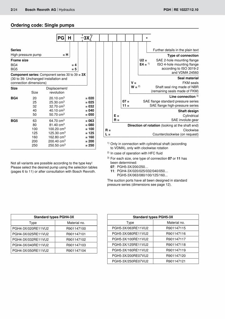
1) Only in connection with cylindrical shaft (according to VDMA), only with clockwise rotation
2) In case of operation with HFC fluid3) For each size, one type of connection 07 or 11 has
been determined: 07: PGH5-3X/200/250… 11: PGH4-3X/020/025/032/040/050… PGH5-3X/063/080/100/125/160...
The suction ports have all been designed in standard pressure series (dimensions see page 12).
Ordering code: Single pumps
SeriesHigh pressure pump = H
Frame sizeBG4 = 4 BG5 = 5Component series: Component series 30 to 39 = 3X (30 to 39: Unchanged installation and connection dimensions)Size
SizeDisplacement/
revolutionBG4 20
25 32 40 50
20.10 cm3 25.30 cm3 32.70 cm3 40.10 cm3
50.70 cm3
= 020 = 025 = 032 = 040 = 050
BG5 63 80 100 125 160 200 250
64.70 cm3
81.40 cm3
100.20 cm3
125.30 cm3
162.80 cm3
200.40 cm3
250.50 cm3
= 063 = 080 = 100 = 125 = 160 = 200 = 250
Further details in the plain textType of connection
U2 = SAE 2-hole mounting flange E4 = 1) ISO 4-hole mounting flange
according to ISO 3019-2 and VDMA 24560
Seal materialV = FKM seals W = 2) Shaft seal ring made of NBR
(remaining seals made of FKM)Line connection 3)
07 = SAE flange standard pressure series 11 = SAE flange high-pressure series
Shaft designE = Cylindrical R = SAE involute gear
Direction of rotation (looking at the shaft end)R = Clockwise L = Counterclockwise (on request)
PG H 3X *
Not all variants are possible according to the type key! Please select the desired pump using the selection tables (pages 6 to 11) or after consultation with Bosch Rexroth.
Standard types PGH4-3XType Material no.
PGH4-3X/020RE11VU2 R901147100PGH4-3X/025RE11VU2 R901147101PGH4-3X/032RE11VU2 R901147102PGH4-3X/040RE11VU2 R901147103PGH4-3X/050RE11VU2 R901147104
Standard types PGH5-3XType Material no.
PGH5-3X/063RE11VU2 R901147115PGH5-3X/080RE11VU2 R901147116PGH5-3X/100RE11VU2 R901147117PGH5-3X/125RE11VU2 R901147118PGH5-3X/160RE11VU2 R901147119PGH5-3X/200RE07VU2 R901147120PGH5-3X/250RE07VU2 R901147121

P
S
372714
6 6
58
S
P
12 7 7 12
1110119
M (measuring port)
Hydraulics Bosch Rexroth AGRE 10227/12.10 PGH 3/24
Function, section, symbol
Symbol
Suction and displacement procedureThe hydro-dynamically mounted pinion shaft (4) drives the toothed internal gear (5) in the direction of rotation shown.The tooth clearances opening in the suction area prime the fluid. The fluid is transported into the tooth clearances of pin-ion and internal gear, from the suction area (S) into the pres-sure area (P).There, the fluid is displaced from the closing tooth clearanc-es and delivered into the pressure port (P).Suction and discharge area are separated by the radial com-pensation elements (9 to 11) and the tooth engagement be-tween internal gear and pinion shaft.Axial compensationThe displacement chamber in the pressure area is axially sealed by axial washers (7).
A small compressive force component presses segment and segment support onto the tooth tips of pinion shaft and in-ternal gear and in this way provides for the separation of the pressure area from the suction area with automatic clearance adjustment.This is the prerequisite for constantly high volumetric efficien-cy during the entire operating time.The clearance adjustment of segment and segment support is made possible by the seal rolls located inbetween.
Hydro-dynamic and hydrostatic mountingThe pinion shaft (4) is accepted by hydro-dynamically lubri-cated radial sliding bearings (6).The internal gear (5) is mounted hydrostatically in the housing.GearingThe gearing with involute edges has a large meshing length for little flow and pressure pulsation and thus guarantees low-noise running.
The sides of the axial washers facing away from the dis-placement area are backed by a pressure field (12). These fields balance the axial washers vis-à-vis the displacement area, which results in a perfect sealing with low mechani-cal losses.
StructureHydraulic pumps of type PGH.-3X are gap-compensated in-ternal gear pumps with fixed displacement.They mainly consist of: Mounting flange (1), housing (2),
cover with through-drive (3), pinion shaft (4), internal gear (5), sliding bearings (6), axial washers (7) and stop pin (8) as well as the radial compensation consisting of seg-ment (9), segment support (10) and the seal rolls (11).
Radial compensationThe radial compensation elements consist of segment (9), segment support (10) and seal rolls (11).Segment (9) and segment support (10) are arranged in the pressure field so that the resulting compressive force is basi-cally accepted by the stop pin.

4/24 Bosch Rexroth AG Hydraulics PGH RE 10227/12.10
Technical Data (For applications outside these parameters, please consult us!)
generalDesign Internal gear pump, gap-compensated
Type of connection SAE 2-hole flange according to ISO 3019-1 or 4-hole flange according to VDMA 24560 and ISO 3019-2
Line connection Flange port
Shaft load Radial and axial forces (e.g. belt pulley) only after coordination
Direction of rotation (looking at the shaft end) Clockwise or counterclockwise (on request) – not bidirectional!
hydraulicHydraulic fluid HLP – mineral oil according to DIN 51524 part 2
HFC – water polymer solutions according to DIN EN ISO 12922 1) 2): Seal design WHEES – fluids according to DIN ISO 15380 1)
HFD-U – fluids according to VDMA 24317 1), DIN EN ISO 12922 1)
Please observe our specifications according to data sheet RE 90220 Other fluids on request!
Hydraulic fluid HLP fluid °C –10 to +80; for other temperatures please consult us!
temperature range Special fluid °C –10 to +50; for other temperatures please consult us!
Ambient temperature range °C –20 to +60
Viscosity range mm2/s 10 to 300 (to n = 1800 min-1)10 to 100 (to n = 3000 min-1)2000 admissible start viscosity (400 to 1800 min-1)
Max. admissible level of contamination of the hydraulic fluid cleanliness class according to ISO 4406 (c)
Class 20/18/15 3)
1) Attention! To these media, the limitations for special fluids apply2) Hydraulic fluid HFC: Input speed nmax = 2000 min-1
3) The cleanliness classes specified for the components must be adhered to in hydraulic systems. Efficient filtration prevents failures and simultaneously increases the service life of the components. For the selection of filters, see data sheets RE 50070, RE 50076, RE 50081, RE 50086 and RE 50088.

Hydraulics Bosch Rexroth AGRE 10227/12.10 PGH 5/24
Technical Data (For applications outside these parameters, please consult us!)
Frame size Frame size PGH4Size Size 20 25 32 40 50Weight m kg 14 14.5 15 16 17Speed range 1) nmin min-1 200 200 200 200 200
nmax min-1 3000 3000 3000 3000 3000Displacement V cm3 20.1 25.3 32.7 40.1 50.7Flow 2) qV l/min 28.9 36.3 46.9 57.6 72.8Moment of inertia (around drive axis) J kgm2 0.00037 0.00045 0.00055 0.00066 0.00081
Power consumption Pad kWMin. drive power necessary (with p ≈ 1 bar) 1.1 1.1 1.1 1.1 1.5Max. admissible drive power 35 44 56 61 76
Operating pressure, absolute – Input
p
bar
0.8 to 2 (shortly, upon start 0.6 bar)
Nominal pressure pN bar– Output, continuous HLP fluid 315 250
Special fluid 3) 220 175intermittent 4) pmax bar
HLP fluid 350 315Special fluid 3) 245 210
Frame size Frame size PGH5Size Size 63 80 100 125 160 200 250Weight m kg 42 43.5 45.5 48 52 55.5 60.5Speed range 1) nmin min-1 200 200 200 200 200 200 200
nmax min-1 3000 3000 3000 3000 3000 3000 3000Displacement V cm3 64.7 81.4 100.2 125.3 162.8 200.4 250.5Flow 2) qV l/min 92.8 116.9 143.8 179.8 233.7 287.7 359.6Moment of inertia (around drive axis) J kgm2 0.00237 0.00289 0.00329 0.00407 0.00506 0.00623 0.00760
Power consumption Pad kWMin. drive power necessary (with p ≈ 1 bar) 1.8 2.2 3 4 5.5 7.5 7.5Max. admissible drive power 96 103 129 161 134 140 134
Operating pressure, absolute – Input
p
bar
0.8 to 2 (shortly, upon start 0.6 bar)
Nominal pressure pN bar– Output, continuous HLP fluid 315 210 170 135
Special fluid 3) 220 145 115 90intermittent 4) pmax bar
HLP fluid 350 260 210 170Special fluid 3) 245 180 145 115
1) Hydraulic fluid HFC: Input speed nmax = 2000 min-1 2) Measured with n = 1450 min–1, p = 10 bar and = 30 mm2/s3) Attention! To these media, the limitations for special fluids apply4) Max 10 s, max. 50 % of the duty cycle

68,9 70
146
174
14,3
74,6
81,460
101,
6 h8
9,7
70 L2
L3
L1
12,5
5,4
25 j6 28
������
������
������
����
����
����
����
�
����
����
���������������
����
��
������
������
������ ������
������
����
��
����
��
����
����
����
������S
P
50,37
���������������8 h9
����
����
����
����
2)
6/24 Bosch Rexroth AG Hydraulics PGH RE 10227/12.10
Unit dimensions of frame size 4 (dimensions in mm [inch])
Material no. "L" counter- clockwiseType Size "R" clockwise L1 L2 L3 S 1) P 1)
PGH4-3X/020..E11VU2 R901147100 On request145 70.5 129
1" S 3/4" H[5.71] [2.78] [5.08]
PGH4-3X/025..E11VU2 R901147101 On request150 73 134
1 1/4" S 3/4" H[5.91] [2.87] [5.28]
PGH4-3X/032..E11VU2 R901147102 On request157 76.5 141
1 1/2" S 1" H[6.18] [3.01] [5.55]
PGH4-3X/040..E11VU2 R901147103 On request164 80 148
1 1/2" S 1" H[6.46] [3.15] [5.83]
PGH4-3X/050..E11VU2 R901147104 On request174 85 158
2" S 1" H[6.85] [3.35] [6.22]
Drive shaft cylindrical, SAE 2-hole mounting flange
1) S = Standard pressure series; H = High-pressure series; exact dimensions see table page 12
2) For multiple pumps, the combination part starts from here
The figure shows a pump with clockwise rotation, in case of pumps with counterclockwise rotation, the pressure port is on the opposite side!
PGH4-3X/... E...VU2R L

Drive shaft cylindrical, 4-hole mounting flange according to ISO 3019-2 and VDMA 24560
PGH4-3X/... RE...VE4
2)
Hydraulics Bosch Rexroth AGRE 10227/12.10 PGH 7/24
Unit dimensions of frame size 4 (dimensions in mm [inch])
Material no.Type Size "R" clockwise L1 L2 L3 S 1) P 1)
PGH4-3X/020RE11VE4 R901147105145 70.5 129
1" S 3/4" H[5.71] [2.78] [5.08]
PGH4-3X/025RE11VE4 R901147106150 73.0 134
1 1/4" S 3/4" H[5.91] [2.87] [5.28]
PGH4-3X/032RE11VE4 R901147107157 76.5 141
1 1/2" S 1" H[6.18] [3.01] [5.55]
PGH4-3X/040RE11VE4 R901147108164 80 148
1 1/2" S 1" H[6.46] [3.15] [5.83]
PGH4-3X/050RE11VE4 R901147109174 85 158
2" S 1" H[6.85] [3.35] [6.22]
1) S = Standard pressure series; H = High-pressure series; exact dimensions see table page 12
2) For multiple pumps, the combination part starts from here

S
38
9,7
46 L2L3
L1
12,5
5,4
68,9 70
146
174
14,3
74,6
81,4
������
������
����
����
����
����
�
������
����
����
����
������
������������
������
����
��
������
����
���
����
��������
P
50,37
101,
6 h8
83
8/24 Bosch Rexroth AG Hydraulics PGH RE 10227/12.10
Unit dimensions of frame size 4 (dimensions in mm [inch])
Material no. Type
Size
"R" clockwise
"L" counter-clockwise
L1
L2
L3
S 1)
P 1)
PGH4-3X/020..R11VU2 R901147110 On request145 70.5 129
1" S 3/4" H[5.71] [2.78] [5.08]
PGH4-3X/025..R11VU2 R901147111 On request150 73 134
1 1/4" S 3/4" H[5.91] [2.87] [5.28]
PGH4-3X/032..R11VU2 R901147112 On request157 76.5 141
1 1/2" S 1" H[6.18] [3.01] [5.55]
PGH4-3X/040..R11VU2 R901147113 On request164 80 148
1 1/2" S 1" H[6.46] [3.15] [5.83]
PGH4-3X/050..R11VU2 R901147114 On request174 85 158
2" S 1" H[6.85] [3.35] [6.22]
Drive shaft splined, SAE 2-hole mounting flange(central and back pump in pump combinations)
R LPGH4-3X/... R...VU2
1) S = Standard pressure series; H = High-pressure series; exact dimensions see table page 12
2) For pump combinations, the combination part starts from here
Shaft 25-4; SAE J744 JUL 88;Involute gearANSI B92.1a-1976,15T 16/32 DP 30°
2)
The figure shows a pump with clockwise rotation, in case of pumps with counterclockwise rotation, the pressure port is on the opposite side!

152,
4 h8
92 L2
L3L1
7,7
17
9
82
40 j6
������
������
������
����
����
���
������
������
������
��������������������������
����
��
������
����
����
��
S
P43
12 h9
99
116,
2
267
105,
3
22
228,6
68,4
105
������
������
������
������������������
������
�������
������
������
������
������
2)
Hydraulics Bosch Rexroth AGRE 10227/12.10 PGH 9/24
Unit dimensions of frame size 5 (dimensions in mm [inch])
Drive shaft cylindrical, SAE 2-hole mounting flange
R LPGH5-3X/... E...VU2
Material no.
Type Size "R" clockwise"L" counter-clockwise L1 L2 L3 S 1) P 1)
PGH5-3X/063..E11VU2 R901147115 On request210 105.5 194
2" S 1 1/4" H[8.27] [4.15] [7.64]
PGH5-3X/080..E11VU2 R901147116 On request218 109.5 202
2" S 1 1/4" H[8.58] [4.31] [7.95]
PGH5-3X/100..E11VU2 R901147117 On request227 114 211
2 1/2" S 1 1/2" H[8.94] [4.49] [8.31]
PGH5-3X/125..E11VU2 R901147118 On request239 120 223
2 1/2" S 1 1/2" H[9.41] [4.72] [8.78]
PGH5-3X/160..E11VU2 R901147119 On request257 129 241
3" S 2" H[10.12] [5.08] [9.49]
PGH5-3X/200..E07VU2 R901147120 On request275 138 259
3 1/2" S 2" S[10.83] [5.43] [10.20]
PGH5-3X/250..E07VU2 R901147121 On request299 150 283
3 1/2" S 2 1/2" S[11.77] [5.91] [11.14]
1) S = Standard pressure series; H = High-pressure series; exact dimensions see table page 12
2) For pump combinations, the combination part starts from here
The figure shows a pump with clockwise rotation, in case of pumps with counterclockwise rotation, the pressure port is on the opposite side!

68,4 ������
12 h9
99
116,
2
230
105,
3
200
105
43
17,5
������
������
�������������������
������
������
������
������
������
������
92 L2
L3
L1
7,7
18
82
40 j6
9
������
������
������
��������
�����
������
������
������
����������������������������
������
������
����
����
��
P
S
160
h8
2)
10/24 Bosch Rexroth AG Hydraulics PGH RE 10227/12.10
Unit dimensions of frame size 5 (dimensions in mm [inch])PGH5-3X/...RE...VE4
Drive shaft cylindrical, 4-hole mounting flange according to ISO 3019-2 and VDMA 24560
1) S = Standard pressure series; H = High-pressure series; exact dimensions see table page 12
2) For pump combinations, the combination part starts from here
Material no.
Type Size "R" clockwise L1 L2 L3 S 1) P 1)
PGH5-3X/063RE11VE4 R901147122210 105.5 194
2" S 1 1/4" H[8.27] [4.15] [7.64]
PGH5-3X/080RE11VE4 R901147123218 109.5 202
2" S 1 1/4" H[8.58] [4.31] [7.95]
PGH5-3X/100RE11VE4 R901147124227 114 211
2 1/2" S 1 1/2" H[8.94] [4.49] [8.31]
PGH5-3X/125RE11VE4 R901147125239 120 223
2 1/2" S 1 1/2" H[9.41] [4.72] [8.78]
PGH5-3X/160RE11VE4 R901147126257 129 241
3" S 2" H[10.12] [5.08] [9.49]
PGH5-3X/200RE07VE4 R901147127275 138 259
3 1/2" S 2" S[10.83] [5.43] [10.20]
PGH5-3X/250RE07VE4 R901147128299 150 283
3 1/2" S 2 1/2" S[11.77] [5.91] [11.14]

99
116,
2
213
105,
3
17,5
181
68,4
105
������
������
������
������
������
������
������
������11
3
127
h8
54
62
9
L2
L3
L1
7,7
17
������
������
������
������
������
����
����
����
������
�
������
S
P
2)
Hydraulics Bosch Rexroth AGRE 10227/12.10 PGH 11/24
Unit dimensions of frame size 5 (dimensions in mm [inch])R L
Shaft 38-4; SAE J 744 JUL 88; Involute gear ANSI B92.1a-1976, 17T 12/24 DP 30°
Material no.
Type Size "R" clockwise"L" counter-clockwise L1 L2 L3 S 1) P 1)
PGH5-3X/063..R11VU2 R901147129 On request219 114.5 203
2" S 1 1/4" H[8.62] [4.51] [7.99]
PGH5-3X/080..R11VU2 R901147130 On request227 118.5 211
2" S 1 1/4" H[8.94] [4.67] [8.31]
PGH5-3X/100..R11VU2 R901147131 On request236 123 220
2 1/2" S 1 1/2" H[9.29] [4.84] [8.66]
PGH5-3X/125..R11VU2 R901147132 On request248 129 232
2 1/2" S 1 1/2" H[9.76] [5.08] [9.13]
PGH5-3X/160..R11VU2 R901147133 On request266 138 250
3" S 2" H[10.47] [5.43] [9.84]
PGH5-3X/200..R07VU2 R901147134 On request284 147 268
3 1/2" S 2" S[11.18] [5.79] [10.55]
PGH5-3X/250..R07VU2 R901147135 On request308 159 292
3 1/2" S 2 1/2" S[12.13] [6.26] [11.50]
Drive shaft splined, SAE 2-hole mounting flange(central and back pump for pump combinations)
PGH5-3X/... R...VU2
1) S = Standard pressure series; H = High-pressure series; exact dimensions see table page 12
2) For pump combinations, the combination part starts from here
The figure shows a pump with clockwise rotation, in case of pumps with counterclockwise rotation, the pressure port is on the opposite side!

112
G1/420 M10; 18M8; 14
D4D3P1
P2
12/24 Bosch Rexroth AG Hydraulics PGH RE 10227/12.10
D2
D1S1
S2
Ports (dimensions in mm [inch])
Suction port "S" Pressure port "P"
Frame size Size
Porting pattern/ suction port S
D1 D2 S1 S2 Porting pattern/ pressure port P
D3 D4 P1 P2
4
020 1" 5000 PSI Ø25[Ø0.984]
M10; 18 52.4 [2.063]
26.2 [1.032]
3/4" 6000 PSI Ø19 [Ø0.748]
M10; 18 50.8 [2.000]
23.8 [0.937]
025 1 1/4" 4000 PSI Ø32 [Ø1.260]
M10; 18 58.7 [2.311]
30.2 [1.189]
3/4" 6000 PSI Ø19 [Ø0.748]
M10; 18 50.8 [2.000]
23.8 [0.937]
032 1 1/2" 3000 PSI Ø38 [Ø1.496]
M12; 21 69.9 [2.752]
35.7 [1.406]
1" 6000 PSI Ø25.4 [Ø1.000]
M12; 23 57.2 [2.252]
27.8 [1.094]
040 1 1/2" 3000 PSI Ø38 [Ø1.496]
M12; 21 69.9 [2.752]
35.7 [1.406]
1" 6000 PSI Ø25.4 [Ø1.000]
M12; 23 57.2 [2.252]
27.8 [1.094]
050 2" 3000 PSI Ø51 [Ø2.008]
M12; 21 77.8 [3.063]
42.9 [1.689]
1" 6000 PSI Ø25.4 [Ø1.000]
M12; 23 57.2 [2.252]
27.8 [1.094]
5
063 2" 3000 PSI Ø51 [Ø2.008]
M12; 21 77.8 [3.063]
42.9 [1.689]
1 1/4" 6000 PSI Ø32 [Ø1.260]
M12; 21 66.6 [2.622]
31.8 [1.252]
080 2" 3000 PSI Ø51 [Ø2.008]
M12; 21 77.8 [3.063]
42.9 [1.689]
1 1/4" 6000 PSI Ø32 [Ø1.260]
M12; 21 66.6 [2.622]
31.8 [1.252]
100 2 1/2" 2500 PSI Ø64 [2.520]
M12; 23 88.9 [3.500]
50.8 [2.000]
1 1/2" 6000 PSI Ø38 [Ø1.496]
M16; 30 79.3 [3.122]
36.5 [1.437]
125 2 1/2" 2500 PSI Ø64 [2.520]
M12; 23 88.9 [3.500]
50.8 [2.000]
1 1/2" 6000 PSI Ø38 [Ø1.496]
M16; 30 79.3 [3.122]
36.5 [1.437]
160 3" 2000 PSI Ø76 [Ø2.992]
M16; 30 106.4 [4.189]
61.9 [2.437]
2" 6000 PSI Ø51 [Ø2.008]
M20; 35 96.8 [3.811]
44.5 [1.752]
200 3 1/2" 500 PSI Ø89 [Ø3.504]
M16; 30 120.7 [4.752]
69.9 [2.752]
2" 3000 PSI Ø51 [Ø2.008]
M12; 23 77.8 [3.063]
42.9 [1.689]
250 3 1/2" 500 PSI Ø89 [Ø3.504]
M16; 30 120.7 [4.752]
69.9 [2.752]
2 1/2" 2500 PSI Ø64 [Ø2.520]
M12; 23 88.9 [3.500]
50.8 [2.000]
Measuring portPGH4-3X/... and PGH5-3X/... Transport thread PGH4-3X/... Transport thread PGH5-3X/...
Hydraulics Bosch Rexroth AGRE 10227/12.10 PGH 13/24
3X
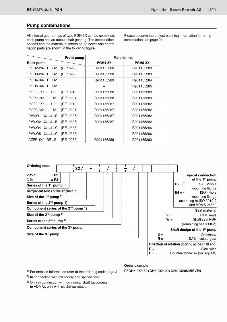
Front pump Material no.Back pump PGH4-3X PGH5-3XPGH2-2X/...R...U2 (RE10223) R901155288 R901155283PGH3-2X/...R...U2 (RE10223) R901155288 R901155283PGH4-3X/...R...U2 R901155289 R901155284PGH5-3X/...R...U2 – R901155285PGF2-2X/...J...U2 (RE10213) R901155288 R901155283PGP2-2X/...J...U2 (RE10231) R901155288 R901155283PGF3-3X/...J...U2 (RE10213) R901155287 R901155282PGP3-3X/...J...U2 (RE10231) R901155287 R901155282PVV/Q1-1X/...J…B (RE10335) R901155287 R901155282PVV/Q2-1X/...J…B (RE10335) R901155287 R901155282PVV/Q4-1X/...J…C (RE10335) – R901155286PVV/Q5-1X/...J…C (RE10335) – R901155286AZPF-1X/...RR...B (RE10089) R901155288 R901155283
Pump combinations
All internal gear pumps of type PGH-3X can be combined; each pump has an output shaft gearing. The combination options and the material numbers of the necessary combi-nation parts are shown in the following figure.
1) For detailed information refer to the ordering code page 22) In connection with cylindrical and splined shaft3) Only in connection with cylindrical shaft (according
to VDMA); only with clockwise rotation
Ordering code
Order example:P3GH5-3X/160+GH5-3X/100+GH4-3X/050REVE4
Please observe the project planning information for pump combinations on page 21.
Type of connection of the 1st pump
U2 = 2) SAE 2-hole mounting flange
E4 = 3) ISO 4-hole mounting flange
according to ISO 3019-2 and VDMA 24560
Seal materialV = FKM seals W = Shaft seal NBR
(remaining seals FKM)Shaft design of the 1st pump
E = Cylindrical R = SAE involute gear
Direction of rotation (looking at the shaft end)R = Clockwise L = Counterclockwise (on request)
2-fold = P23-fold = P3
Series of the 1st pump 1)
Component series of the 1st pump 1)
Size of the 1st pump 1)
Series of the 2nd pump 1)Component series of the 2nd pump 1)
Size of the 2nd pump 1)
Series of the 3rd pump 1)
Component series of the 3rd pump 1)
Size of the 3rd pump 1)

������
�������������������������
101,
6
212
P
S
70L1 L2
L3146
4 x
M12
������������
������
+0,
05+
0.02
������
����
����
��
L4S
14/24 Bosch Rexroth AG Hydraulics PGH RE 10227/12.10
Unit dimensions pump combinations (dimensions in mm [inch])
The dimensional drawings show the front pump and the combination part.
Combination part PGH5-3X+GF3-3X/VV1-1X/VV2-1X/K02Material no.: R901155282
PGH5-3X.. Size
PGH5-3X/..RE..U2PGH5-3X/..RE..E4
L1PGH5-3X/..RR..U2
L163 264 [10.39] 273 [10.75]
80 272 [10.71] 281 [11.06]
100 281 [11.06] 290 [11.42]
125 293 [11.54] 302 [11.89]
160 311 [12.24] 320 [12.60]
200 329 [12.95] 338 [13.31]
250 353 [13.90] 362 [14.25]
PGF3/PGP2Size
L2 L3
20 144.5 [5.69] 79.5 [3.13]
22 146.5 [5.77] 80.5 [3.17]
25 150.5 [5.93] 82.5 [3.25]
32 159.5 [6.28] 87 [3.43]
40 169.5 [6.67] 92 [3.62]
PVV..UMBFrame size L2 L3 (P) L4 (S)
1 156 [6.14] 133 [5.24] 63.5 [2.50]
2 163 [6.42] 38 [1.50] 120.5 [4.75]

130106,5
53,1
82,5
5
47 L3L1 L2
M10
PP
S
������������
������ ������
������
�������������������������
������
����
����
��
+0,
05+
0.01
S
Hydraulics Bosch Rexroth AGRE 10227/12.10 PGH 15/24
Unit dimensions pump combinations (dimensions in mm [inch])The dimensional drawings show the front pump and the combination part.
Combination part PGH5-3X+GH2/3-2X/GF2-2X/AZPF-1X/K01 Material no.: R901155283
PGH5-3X.. Size
PGH5-3X/..RE..U2PGH5-3X/..RE..E4
L1PGH5-3X/..RR..U2
L163 241 [9.49] 250 [9.84]
80 249 [9.80] 258 [10.16]
100 258 [10.16] 267 [10.51]
125 270 [10.63] 279 [10.98]
160 288 [11.34] 297 [11.69]
200 306 [12.05] 315 [12.40]
250 330 [12.99] 339 [13.35]
PGH2Size L2 L3005 110 [4.33] 54 [2.13]006 112.5 [4.43] 55.5 [2.19]008 116 [4.57] 57 [2.24]
PGH3Size L2 L3011 121.5 [4.78] 60 [2.36]013 126.5 [4.98] 62.5 [2.46]016 131.5 [5.18] 65 [2.56]
PGF2/PGP2Size L2 L3006 116 [4.567] 65 [2.559]008 119.5 [4.705] 67 [2.638]011 125 [4.921] 69.5 [2.736]013 130 [5.118] 72 [2.835]016 135 [5.315] 74.5 [2.933]019 141 [5.551] 77.5 [3.051]022 147 [5.787] 80.5 [3.169]
AZPFSize L2 L3004 85 [3.346] 40 [1.575]005 87.5 [3.445] 41 [1.614]008 91.5 [3.602] 43 [1.692]011 96.5 [3.799] 47 [1.850]014 101.5 [3.996] 47.5 [1.870]016 105 [4.134] 47.5 [1.870]019 110 [4.331] 47.5 [1.870]022 115.5 [4.547] 55 [2.165]

70 L3
212
101,
6
L1 L2
P
S
146
4 x
M12
������
������
������������������������
������
����
����
��
����
��
+0,
05+
0.02
������
S
X
View X
16/24 Bosch Rexroth AG Hydraulics PGH RE 10227/12.10
The dimensional drawings show the front pump and the combination part.
Combination part PGH5-3X+GH4-3X..R Material no.: R901155284
Unit dimensions pump combinations (dimensions in mm [inch])
PGH5-3X.. Size
PGH5-3X/..RE..U2PGH5-3X/..RE..E4
L1PGH5-3X/..RR..U2
L163 264 [10.39] 273 [10.75]
80 272 [10.71] 281 [11.06]
100 281 [11.06] 290 [11.42]
125 293 [11.54] 302 [11.89]
160 311 [12.24] 320 [12.60]
200 329 [12.95] 338 [13.31]
250 353 [13.90] 362 [14.25]
PGH4-3X…R..U2Size
L2 L320 145 [5.71] 70.5 [2.78]
25 150 [5.91] 73 [2.87]
32 157 [6.18] 76.5 [3.01]
40 164 [6.46] 80 [3.15]
50 174 [6.85] 85 [3.35]

127
70L1 L2
L3
P
S
������
M16
181213 ������
������
������
�������������������������
+0,
05+
0.02
S
������
����
����
��
X
View X
Hydraulics Bosch Rexroth AGRE 10227/12.10 PGH 17/24
The dimensional drawings show the front pump and the combination part. Combination part PGH5-3X+GH5-3X..R Material no.: R901155285
Unit dimensions pump combinations (dimensions in mm [inch])
PGH5-3X.. Size
PGH5-3X/..RE..U2PGH5-3X/..RE..E4
L1PGH5-3X/..RR..U2
L1
63 264 [10.39] 273 [10.75]
80 272 [10.71] 281 [11.06]
100 281 [11.06] 290 [11.42]
125 293 [11.54] 302 [11.89]
160 311 [12.24] 320 [12.60]
200 329 [12.95] 338 [13.31]
250 353 [13.90] 362 [14.25]
PGH5-3X…R..U2Size L2 L363 219 [8.62] 114.5 [4.51]
80 227 [8.94] 118.5 [4.67]
100 236 [9.29] 123 [4.84]
125 248 [9.76] 129 [5.08]
160 266 [10.47] 138 [5.43]
200 284 [11.18] 147 [5.79]
250 308 [12.13] 159 [6.26]

������M
16181
70
127
L2
L4
P
S
L1
������
������
���������������������
������
����
����
��
+0,
05+
0.02
S
P
L3
18/24 Bosch Rexroth AG Hydraulics PGH RE 10227/12.10
The dimensional drawings show the front pump and the combination part.
Combination part: PGH5-3X+VV4/5-1X..J Material no. R901155286
Unit dimensions pump combinations (dimensions in mm [inch])
PGH5-3X.. Size
PGH5-3X/..RE..U2PGH5-3X/..RE..E4
L1PGH5-3X/..RR..U2
L1
63 264 [10.39] 273 [10.75]
80 272 [10.71] 281 [11.06]
100 281 [11.06] 290 [11.42]
125 293 [11.54] 302 [11.89]
160 311 [12.24] 320 [12.60]
200 329 [12.95] 338 [13.31]
250 353 [13.90] 362 [14.25]
PVV..UMBFrame size L2 L3 (P) L4 (S)
4 186 [7.32] 38 [1.50] 126 [4.96]
5 216 [8.50] 43 [1.69] 153 [6.02]

Hydraulics Bosch Rexroth AGRE 10227/12.10 PGH 19/24
Project planning information
1. General notesThis project planning information refers to the specific proper-ties of the Rexroth PGH.-3X internal gear pump.Comprehensive general information and suggestions are contained in the hydraulics trainer, edition 3 "Project planning information and design of hydraulic systems", RE 00281.
1.1 Intended useRexroth internal gear pumps are intended for the setup of hy-draulic drive systems in the fields of machine and plant con-struction. During project planning, the basic principles of the EU Machinery Directive or comparable national regulations outside the EU have to be observed.The pumps must not be used in explosive environments in accordance with directive 94/9/EC (ATEX).
1.2 Technical dataThe system or machine manufacturer has to ensure compli-ance with the admissible technical data and operating condi-tions. The pump itself does not contain a device to prevent operation outside the admissible data.All mentioned technical features are average values and are applicable for the specified boundary conditions. In case of modifications to the boundary conditions (e.g. viscosity), the technical data may change as well. Tolerances correspond-ing to the relevant state-of-the-art are possible.Operating the pump outside of the admissible technical data (pages 4, 5) is possible to a certain extent, however, this re-quires the explicit written approval by Bosch Rexroth.
2. Hydraulic project planning
2.1 Bleeding option for commissioningFor Rexroth internal gear pumps PGH.-3X a manual, swit-chable or automatic bleeding option is to be provided for the initial commissioning or re-commissioning after mainte-nance and repair works. As bleeding point, the measurement port (M) available at the pump can be used. Otherwise, the bleeding point has to be put into the pressure line in front of the first valve or check valve. Bleeding may be effected with a maximum counter-pressure of 0.2 bar. Examples of bleedings circuits:1. Automatic bleeding via automatic bleeding valve2. Switchable bleeding3. Manually operated bleeding
2.2 Suction lineThe line cross-sections have to be dimensioned for the de-signed flows in a manner that an ideal suction speed of 0.6 to 1.2 m/s is achieved on average. The suction speed must not exceed a maximum value of 2 m/s. The suction cross-sections at the pump itself are dimen-sioned for the maximum flow and thus are a reference only. In case of continuous operation with speeds lower than the admissible maximum speed, the suction tube diameter is to be dimensioned smaller than the suction port of the pump in accordance with the actual suction speed. All in all, the suction line has to be designed in a way that the admissible inlet operating pressure is complied with (0.8 to 2 bar absolute)! Bends and a combination of the suction tubes of several pumps must be avoided. If suction filters have to be used, it has to be ensured on the system side that the lowest admissible inlet operating pressure is not exceed-ed even when the filter is contaminated. Please ensure air tightness of the transitions and dimen-sional stability of the suction hose as regards to the external air pressure. The suction tube immersion depth should be selected as large as possible. Depending on the internal reservoir pres-sure, the viscosity of the operating medium, and the flow ra-tios within the reservoir, no vortex must be formed even dur-ing maximum flow. Otherwise there is the risk of sucking in air.We recommend selecting suction tubes according to AB 23-03.
min
50
mm
Suction line
max. 0,2 bar
1. 2. 3.

20/24 Bosch Rexroth AG Hydraulics PGH RE 10227/12.10
Project planning information
2.3 Pressure lineWith pressure lines, sufficient bursting resistance of the tubes, hoses and connection elements has to be ensured. The cross-sections should be based on the maximum flow in order to avoid additional excessive load of the pump due to backpressure. In this connection, you must also consider the pipe losses across the entire pressure line length and other line resistances (e.g. bends, pressure filters).
2.4 Pressure limitationThe internal gear pump PGH is not equipped with devices for compliance with the maximum operating pressure. Setting and limiting the admissible operating pressure has to be en-sured on the system side.The pressure relief valves necessary for that purpose are to be designed considering the maximum flow and the existing pressure increase speed so that the admissible intermittent operating pressure is not exceeded.
2.5 Pressure holding functionIn the variable-speed drive, the pump can temporarily also be operated below the specified minimum speed, in the pressure holding function. The holding time and the related necessary speed result from the operating viscosity and the pressure level. For the design, please contact Bosch Rexroth's Tech-nical Sales. In the deactivated condition (speed = 0), a leakage flow flows through the pump back into the reservoir, depending on the load pressure. If this is to be securely prevented, a check valve has to be used. When using a check valve, please observe the information on bleeding in chapter 2.1.
3. Mechanical project planning
3.1 Installation and disassembly optionFor installing and disassembling the pump on or from the drive, accessibility has to be provided for on the system side by means of suitable lifting gear. Please consider especially the own weight of frame size PGH 5 (see "Technical Data", page 5).Screws of the property class 8.8 or 10.9 have to be provided for mounting purposes.
3.2 MountingOn the machine side, the screws have to be accessible in a way that the required tightening torque can be applied. The tightening torque is based on the operating conditions and in-volved elements of the screw connection and has to be speci-fied by the manufacturer in the power unit, machine or system project planning.
3.3 Reservoir In the reservoir construction or the selection of suitable stan-dard reservoirs, the following requirements are to be ob-served:– Selection of the largest reservoir volume possible, depend-
ing on the continuous or average flow, in order to allow for the separation of air bubbles by means of enough dwell time of the medium in the reservoir. In this connection, the air separation capability of the fluid used is also important.
– Provision of settling zones for the fluid in the reservoir in order to allow for air separation.
– Provision of guiding plates in order to allowing for the de-posit of contamination at the reservoir bottom outside the pump suction area.
– Large dimensioning of the reservoir surfaces depending on the heat output to be dissipated via the reservoir walls.
3.4 Required power unit functionsHydraulic power units should at least be equipped with the following features:– Reservoirs, the internal pressure of which corresponds to
the ambient pressure in accordance with the design, have to be equipped with ventilation filters for pressure compen-sation purposes.
– The fluid should be filled by means of filling connections only excluding filling with unfiltered fluid.
– Pollution or humidity must be prevented from getting into the system. When using the pump in a highly polluted environ-ment, the reservoir is to be pre-tensioned by means of air pressure for this. If cleansing of the external reservoir side is intended or to be expected during the period of use, res-ervoir fittings for tubes, lines, or hoses have to be selected, which ensure safe seal against external pressurization with water jet.
3.5 Place of installation and ambient conditionsWith places of installation from a geodetic height of more than 1000 m, the pump is to be arranged in or below the reser-voir or the reservoir is to be pre-tensioned by means of com-pressed air in order to comply with the admissible minimum inlet pressure. The suction line is to be selected short and with a large cross-section, bends should not be used.When installing the pump more than 10 m below the reservoir, the reduction of the inlet pressure to the maximum admissible value has to be ensured by means of additional measures.When operating the pump in salt-containing or corrosive envi-ronments or when pressurization with strongly abrasive sub-stances is possible, it has to be ensured on the system side that the shaft seal ring and the sealing area of the shaft do not make direct contact with the environment.

Hydraulics Bosch Rexroth AGRE 10227/12.10 PGH 21/24
Project planning information
3.6 Installation positions
IM B5
IM V1
IM B3 IM V2
Attention!Installation position motor at bottom and pump at top(e.g. IM V2) is not admissible!
• Apumpstagedrivetorqueiscalculatedasfollows:
T : Torque in Nmp : Operating pressure in bar
V : Displacement in cm3
η : Hydraulic-mechanical efficiency
4. Pump combinations•It has to be ensured with pump combinations that the
operating data admissible for the relevant pump type is complied with in every stage.
• Thecombinedpumpsmustallhavethesamedirectionof rotation.
• The pump with the largest torque, variable displacement pumps or pumps with intermittent load are to be provided as first stage in the pump combination.
• Themaximumthrough-drivetorquemustbecheckedbythe project planner for every application. This also applies to already existing (encoded) pump combinations.
Maximum admissible torques in Nm:
Type Drive torque Output torqueCylindrical shaft ..E Splined shaft ..R
PGH4 450 450 280PGH5 1100 1400 700
• Thetotalofthetorquesinapumpcombinationmustnotexceed the max. drive torque.
• Jointaspirationisnotpossible.• Forreasonsofstability,werecommendtheISO4-hole
mounting flange according to VDMA "E4" for combinations of three and more pumps
T =p • V • 0.0159η hydr.-mech.
• Beforeoperatingpumpcombinationswithdifferentmedi-ums, please consult Bosch Rexroth.
• Centralandbackpumpsmusthavetheshaftdesign"R" (splined).

22/24 Bosch Rexroth AG Hydraulics PGH RE 10227/12.10
5. Maintenance schedule and operational safetyFor safe operation and a long service life of the pump, a main-tenance schedule has to be developed for the power unit, the machine, or the system. The maintenance schedule has to ensure that the intended or admissible operating conditions of the pump are complied with during the period of use.
In particular, compliance with the following operating param-eters has to be ensured:– The required oil cleanliness– The operating temperature range– The level of the operating medium
Furthermore, the pump and the system have to be checked for modifications of the following parameters on a regular basis: – Vibrations– Noise– Temperature difference pump – fluid in the reservoir – Foam formation in the reservoir– Leak-proofness
Modifications of these parameters indicate wear of compo-nents (e.g. drive motor, coupling, pump, etc.). The cause has to be determined and remedied immediately. In order to achieve high operational safety of the pump in the machine or system, we recommend checking the param-eters mentioned above continuously and automatically and shutting the system down automatically in case of modifica-tions exceeding the usual fluctuations in the intended operat-ing range.Plastic components of drive couplings should be replaced reg-ularly, however, after 5 years at the latest. The corresponding information of the manufacturer is to be observed. For preventive maintenance of the pump, we recommend having the seals replaced after a maximum operating period of 5 years by an authorized Bosch Rexroth service company.
Project planning information
6. Accessories
6.1 SAE connection flanges We recommend selecting the SAE flanges for suction and pressure port according to AB 22-15 (with welded connec-tion) or AB 22-13 (with threaded connection).
6.2 Pump safety blockFor limiting the operating pressure and for the pump circula-tion at zero pressure, we recommend our pump safety blocks type DBA… according to RE 25890.Automatic bleeding upon commissioning is, however, not possible via DBA blocks. In this connection, we recommend a separate manual or automatic bleeding, e.g. via the pump's measurement port (see page 19)!
6.3 Other accessoriesTo install the Rexroth PGH.-3X internal gear pump on electric motors, we recommend selecting the pump mounting brack-ets according to AB 41-20 and torsionally flexible couplings according to AB 33-22.

Hydraulics Bosch Rexroth AGRE 10227/12.10 PGH 23/24
Commissioning notes
Preparation– Check whether the system has been installed carefully
and cleanly.– Only fill in hydraulic fluid in through a filter with the required
minimum retention rate.– Via suction or pressure pipe, fill the pump completely with
the hydraulic fluid.– Check the direction of rotation for compliance with the di-
rection of rotation according to the pump type.
Bleeding– Open the bleed port at the system or switch to circulation at
zero pressure, according to the system operating instruc-tions. During bleeding, discharge of enclosed air at zero pressure must be guaranteed.
– For bleeding the pump, switch the pump on and immedi-ately off again (jog mode). This process is to be repeated until complete bleeding of the pump is ensured.
– Close the manually opened bleed ports again.
Commissioning– If complete bleeding of the pump has been ensured, switch
on the motor. Let the pump run at zero pressure until the system is completely bled. For the bleeding of the system, the system operating instructions are to be observed.
– Commission the system according to the system operating instructions and load the pump.
– After some operating time, check the hydraulic fluid in the reservoir for bubble or foam formation at the surface.
Operation– Pay attention to changes in the noise characteristic during
operation. Due to heating of the operating medium, minor noise increases are normal. Considerable increase in the noise or random short-term changes in the noise may be an indication of the aspiration of air. If the suction tubes are too short or the operating medium filling levels are too low, air can also be sucked in via a vortex.
– Changes in operating speeds, temperatures, noise in-crease or power consumption are an indication of wear or damage at the system or the pump.
Re-commissioning– Check the pump and the system for leakage. Leaks are an
indication of leakage below the hydraulic fluid level. An in-creased hydraulic fluid level in the reservoir is an indication of leakage above the hydraulic fluid level.
– If the pump is arranged above the hydraulic fluid level, the pump may run empty due to leakage, e.g. a worn shaft seal. In this case, the system must be bled once again dur-ing re-commissioning. Provide for repair.
– After repair and maintenance works, you must bleed the system once again.
– If the system is intact, switch on the motor.
General– The pumps supplied by us have been tested for function
and performance. Modifications of any type at the pump are not permitted since this would result in the invalidation of warranty claims!
– Repairs may only be carried out by the manufacturer or their authorized dealers and agencies. Repairs carried out by the customer are not covered by a warranty.
Important notes– The pump may only be installed, maintained and repaired
by authorized, trained and instructed personnel!– The pump may only be operated within the admissible data
(see page 4 and 5)!– The pump may only be operated if it is in an unobjection-
able condition!– When carrying out any work on the pump, depressurize
the system!– Unauthorized conversions or modifications, which affect
safety and function are not permitted!– Protective devices (e.g. coupling protection) are to be at-
tached and/or existing protective devices must not be re-moved!
– Make sure that all mounting screws are always properly tightened! (Observe the prescribed tightening torque!)
– The generally valid safety and accident prevention regula-tions must imperatively be complied with!

Bosch Rexroth AG HydraulicsZum Eisengießer 197816 Lohr am Main, Germany Phone +49 (0) 93 52 / 18-0 Fax +49 (0) 93 52 / 18-23 [email protected] www.boschrexroth.de
© This document, as well as the data, specifications and other informa-tion set forth in it, are the exclusive property of Bosch Rexroth AG. It may not be reproduced or given to third parties without its consent.The data specified above only serve to describe the product. No state-ments concerning a certain condition or suitability for a certain applica-tion can be derived from our information. The information given does not release the user from the obligation of own judgment and verification. It must be remembered that our products are subject to a natural process of wear and aging.
24/24 Bosch Rexroth AG Hydraulics PGH RE 10223/10.05PGH RE 10227/12.10