Internal Combustion Engine - Bangladesh University of ...teacher.buet.ac.bd/ronin/ME 267-ICE.pdf ·...
24
Internal Combustion Engine 1/38 March 16, 2015 ME 267 Fundamentals of Mechanical Engineering Internal Combustion Engine
-
Upload
vuongxuyen -
Category
Documents
-
view
227 -
download
3
Transcript of Internal Combustion Engine - Bangladesh University of ...teacher.buet.ac.bd/ronin/ME 267-ICE.pdf ·...

Internal Combustion Engine
1/38 March 16, 2015
ME 267
Fundamentals of Mechanical Engineering
Internal Combustion Engine

Internal Combustion Engine
2/38 March 16, 2015
Internal Combustion Engine (ICE)
The Internal Combustion Engine is an engine in which the
combustion of fuel and an oxidizer (typically air) occurs
inside a ‘confined space’ called a combustion chamber.
This ‘exothermic’ reaction creates gases at high
temperature and pressure, which are permitted to expand
inside that confined chamber. Thrust produced by this
expanding gas drives the engine creating useful work.

Internal Combustion Engine
3/38 March 16, 2015
Classification of ICE

Internal Combustion Engine
4/38 March 16, 2015
Classification of ICE
Spark Ignition (SI) IC Engine
Inside the combustion chamber of this type of
engine, the mixture of fuel and air is ignited by a ‘spark
plug’ to initiate the exothermic combustion reaction.
Compression Ignition (CI) IC Engine
This type of IC Engine does not have spark plug.
Inside the combustion chamber of this engine, air is
compressed to a high enough pressure and temperature
that combustion occurs ‘spontaneously’ when fuel is
injected at the end of air-compression.
Internal Combustion Engine
5/38 March 16, 2015
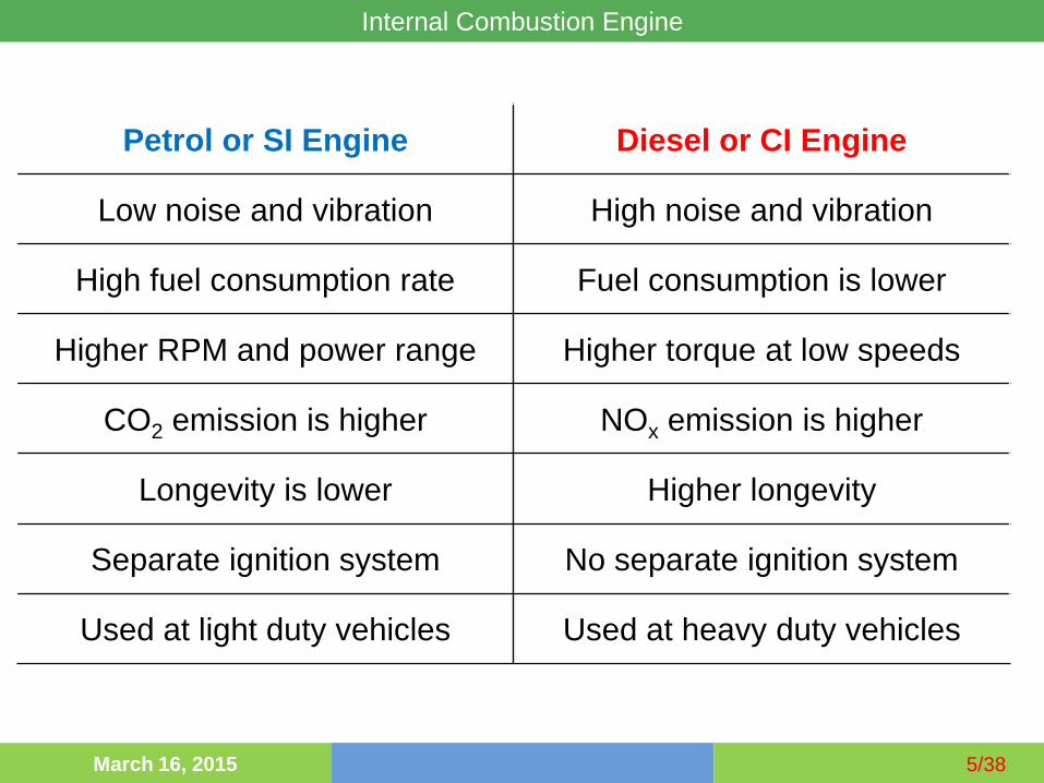
Petrol or SI Engine Diesel or CI Engine
Low noise and vibration High noise and vibration
High fuel consumption rate Fuel consumption is lower
Higher RPM and power range Higher torque at low speeds
CO2 emission is higher NOx emission is higher
Longevity is lower Higher longevity
Separate ignition system No separate ignition system
Used at light duty vehicles Used at heavy duty vehicles

Internal Combustion Engine
6/38 March 16, 2015
Engine Terminology

Internal Combustion Engine
7/38 March 16, 2015
Actual 4-stroke Engine P-V Diagram 1. Intake Stroke
2. Compression Stroke
3. Power Stroke
4. Exhaust Stroke

Internal Combustion Engine
8/38 March 16, 2015
Complexities in analysis of actual engine cycle
- Considering the composition change during combustion
- Calculation of friction loss, pressure and temp. gradients
- Heat loss from the cylinder
- Calculation of work required to charge and purge cylinder
Air-standard assumptions for simpler qualitative analysis
- Working fluid is only air which takes and rejects heat
- No intake and exhaust stroke
- No frictional and heat loss
Air-standard cycles
1. Otto or Petrol cycle & 2. Diesel cycle

Internal Combustion Engine
9/38 March 16, 2015
Air-standard OTTO Cycle (SI Engine)
a b

Internal Combustion Engine
10/38 March 16, 2015
Air-standard OTTO Cycle (SI Engine)
Process 1-2: Isentropic Compression.
Piston: BDC TDC
Process 2-3: Constant Volume Heat Addition.
Piston: at TDC
Process 3-4: Isentropic Expansion (Power Stroke)
Piston: TDC BDC
Process 4-1: Constant Volume Heat Rejection.
Piston: at BDC

Internal Combustion Engine
11/38 March 16, 2015
Air-standard OTTO Cycle (SI Engine)
In the p-v diagram
Area 1-2-a-b-1: Work input per unit mass during the compression
process.
Area 3-4-b-a-3: Work done per unit mass in the expansion process.
Area 3-4-1-2: Net Work Output.
In the T-s diagram
Area 2-3-a-b-2: Quantity of Heat added to unit mass of air from any
External Source.
Area 1-4-a-b-1: Quantity of Heat rejected to unit mass of air from any
External Source.
Area 1-2-3-4: Quantity of Net heat added to unit mass of air from any
External Source.

Internal Combustion Engine
12/38 March 16, 2015
Air-standard DIESEL Cycle (CI Engine)

Indicated Work
Given the cylinder pressure data over the operating
cycle of the engine one can calculate the work done
by the gas on the piston.
The indicated work per cycle is pdVWi
Compression
W<0
Power
W>0 Intake
W>0
Exhaust
W<0
WA > 0
WB < 0

Pi = Wi N / nR w/units: (kJ/cycle) (rev/s) / (rev/cycle)
where N – crankshaft speed in rev/s
nR – number of crank revolutions per cycle
= 2 for 4-stroke
= 1 for 2-stroke
Power can be increased by increasing:
• the engine size, Vd
• compression ratio, rc
• engine speed, N
Indicated Power

Mechanical Efficiency
Some of the power generated in the cylinder is used
to overcome engine friction. The friction power is
used to describe these losses:
Pf = Pi - Pb
Friction power can be measured by motoring the engine.
The mechanical efficiency is defined as:
m = Pb / Pi = 1- (Pf / Pi )
Mechanical efficiency depends on throttle position, engine
design, and engine speed. Typical values for car engines
at WOT are 90% @2000 RPM and 75% @ max speed.

Internal Combustion Engine
16/38 March 16, 2015
mean effective pressure
The MEP (mean effective pressure) is the theoretical
constant pressure that, if acted on the piston during the
power stroke, would produce the same net work as
actually developed in one cycle.
minmax VV
WnetMEP

Internal Combustion Engine
17/38 March 16, 2015
Otto cycle

Internal Combustion Engine
18/38 March 16, 2015

Internal Combustion Engine
19/38 March 16, 2015

Internal Combustion Engine
20/38 March 16, 2015
Diesel Cycle

Internal Combustion Engine
21/38 March 16, 2015

Internal Combustion Engine
22/38 March 16, 2015

Internal Combustion Engine
23/38 March 16, 2015
An ideal Diesel cycle with air as the working fluid has a
compression ratio of 18 and a cutoff ratio of 2. At the beginning
of the compression process, the working fluid is at 101.325
KPa, 27°C, and 1917 cm3. Utilizing the cold-air-standard
assumptions, determine- (a) the temperature and pressure of air
at the end of each process, (b) the net work output and the
thermal efficiency, and (c) the mean effective pressure.

Internal Combustion Engine
24/38 March 16, 2015