Interlocking Problem in Automatic Disassembly Planning and ...
22
University of Birmingham Interlocking Problem in Automatic Disassembly Planning and Two Solutions Lan, Feiying; Wang, Yongjing Wang; Pham, Duc; Liu, Jiayi; Huang, Jun; Ji, Chunqian; Su, Shizhong; Xu, Wenjun; Liu, Quan; Zhou, Zude Citation for published version (Harvard): Lan, F, Wang, YW, Pham, D, Liu, J, Huang, J, Ji, C, Su, S, Xu, W, Liu, Q & Zhou, Z 2019, Interlocking Problem in Automatic Disassembly Planning and Two Solutions. in Lecture Notes in Electrical Engineering: ICINCO 2018. vol. 613, pp. 193-213. Link to publication on Research at Birmingham portal General rights Unless a licence is specified above, all rights (including copyright and moral rights) in this document are retained by the authors and/or the copyright holders. The express permission of the copyright holder must be obtained for any use of this material other than for purposes permitted by law. • Users may freely distribute the URL that is used to identify this publication. • Users may download and/or print one copy of the publication from the University of Birmingham research portal for the purpose of private study or non-commercial research. • User may use extracts from the document in line with the concept of ‘fair dealing’ under the Copyright, Designs and Patents Act 1988 (?) • Users may not further distribute the material nor use it for the purposes of commercial gain. Where a licence is displayed above, please note the terms and conditions of the licence govern your use of this document. When citing, please reference the published version. Take down policy While the University of Birmingham exercises care and attention in making items available there are rare occasions when an item has been uploaded in error or has been deemed to be commercially or otherwise sensitive. If you believe that this is the case for this document, please contact [email protected] providing details and we will remove access to the work immediately and investigate. Download date: 10. Dec. 2021
Transcript of Interlocking Problem in Automatic Disassembly Planning and ...

University of Birmingham
Interlocking Problem in Automatic DisassemblyPlanning and Two SolutionsLan, Feiying; Wang, Yongjing Wang; Pham, Duc; Liu, Jiayi; Huang, Jun; Ji, Chunqian; Su,Shizhong; Xu, Wenjun; Liu, Quan; Zhou, Zude
Citation for published version (Harvard):Lan, F, Wang, YW, Pham, D, Liu, J, Huang, J, Ji, C, Su, S, Xu, W, Liu, Q & Zhou, Z 2019, Interlocking Problemin Automatic Disassembly Planning and Two Solutions. in Lecture Notes in Electrical Engineering: ICINCO 2018.vol. 613, pp. 193-213.
Link to publication on Research at Birmingham portal
General rightsUnless a licence is specified above, all rights (including copyright and moral rights) in this document are retained by the authors and/or thecopyright holders. The express permission of the copyright holder must be obtained for any use of this material other than for purposespermitted by law.
•Users may freely distribute the URL that is used to identify this publication.•Users may download and/or print one copy of the publication from the University of Birmingham research portal for the purpose of privatestudy or non-commercial research.•User may use extracts from the document in line with the concept of ‘fair dealing’ under the Copyright, Designs and Patents Act 1988 (?)•Users may not further distribute the material nor use it for the purposes of commercial gain.
Where a licence is displayed above, please note the terms and conditions of the licence govern your use of this document.
When citing, please reference the published version.
Take down policyWhile the University of Birmingham exercises care and attention in making items available there are rare occasions when an item has beenuploaded in error or has been deemed to be commercially or otherwise sensitive.
If you believe that this is the case for this document, please contact [email protected] providing details and we will remove access tothe work immediately and investigate.
Download date: 10. Dec. 2021

Interlocking Problem in AutomaticDisassembly Planning and Two Solutions
Feiying Lan1, Yongjing Wang1(&), Duc Truong Pham1, Jiayi Liu1,2,Jun Huang1, Chunqian Ji1, Shizhong Su1, Wenjun Xu2, Quan Liu2,
and Zude Zhou2
1 The University of Birmingham, Edgbaston, Birmingham B15 2TT, UK{fxl655,jxl1012}@student.bham.ac.uk,
{y.wang,d.t.pham,j.huang.1,c.ji,s.su.2}@bham.ac.uk2 Wuhan University of Technology, Wuhan 430070, China{xuwenjun,quanliu,zudezhou}@whut.edu.cn
Abstract. In remanufacturing, disassembly is the first step to dismantle theend-of-life products into components, which is labour-intensive due to thevariability of returned products. Compared to manual disassembly, roboticdisassembly is a promising technique to automate remanufacturing processes,which liberates the human labours from the repetitive disassembly operations.However, it requires predesigned disassembly sequences which are plannedmanually. Several planning methods have been proposed to remove removableparts sequentially. However, those methods can fail in the disassembly sequenceplanning task if the product has interlocked components. This paper firstexplains the interlocking problem and then proposes two solutions. One solutionis to identify subassemblies by using ‘separable pairs’. It complements con-ventional sequential disassembly planning methods and enables automaticdetection of subassemblies online. Another method is based on a divide-and-conquer disassembly strategy which allows subassemblies to be detected beforedisassembly. This approach generates disassembly sequence plans that arehierarchical to avoid interlocking problems and reduce computationalcomplexity.
Keywords: Remanufacturing � Disassembly planning � Dismantling roboticdisassembly � Divide-and-conquer strategy � Hierarchy analysis
1 Introduction
Remanufacturing is “the rebuilding of a product to specifications of the originalmanufactured product using a combination of reused, repaired and new parts” [6].Disassembly is an important feature that distinguishes remanufacturing from conven-tional manufacturing. It is labour intensive with complex operations involved, which iscarried out manually due to the variability in the condition of the returned products.
A study of the robotic disassembly of a PC [7] in the mid-1990s started the researchon automated disassembly systems. Afterwards, the successful attempts at dismantlingelectrical devices and automotive components [1, 2, 14] showed more encouraging
© Springer Nature Switzerland AG 2020O. Gusikhin and K. Madani (Eds.): ICINCO 2018, LNEE 613, pp. 193–213, 2020.https://doi.org/10.1007/978-3-030-31993-9_9

results. These experiments were mostly product-oriented and based on pre-programmed sequences. Compared with ‘automated disassembly with pre-programmed disassembly sequence, a key advance of ‘autonomous’ disassembly isthat machine can interpret product structure and plan the disassembly sequence.A popular approach is based on graphs [8, 13]. Many algorithms and rule-basedmethods have been used to calculate disassembly sequences, for example, the FuzzyReasoning Petri Net proposed by Zhao and Li [16]. However, a graph cannot begenerated exclusively by machine understanding. It requires human’s interpretation.
Smith et al. proposed a method to plan disassembly sequences based on fivematrices with several rules to represent an assembly [9, 11]. Tao et al. modified thematrices to enable partial/parallel disassembly [12]. However, the complexity of themathematical representation of an assembly is not reduced in this optimisation-focusedwork. Besides, it requires to distinguish fasteners and general parts due to their fuzzydefinitions. For example, it might be confused whether an object in press-fit componentshould be categorised as a fastener or a general part. Jin et al. [4, 5] proposed anothermatrix-based method in which the relationships of components were described by just amatrix.
The matrix-based methods work well on sequential disassembly tasks, but they failif the product has interlocked components. In this case, breaking an assembly intosubassemblies is required in disassembly plans. Based on an analysis of over 239mechanical products by the authors’ team, 23% of them contain interlocked compo-nents [3]. They cannot be correctly dealt with using conventional sequential disas-sembly planning methods.
This paper presents two solutions. One is to identify subassemblies by using‘separable pairs’ to complements conventional sequential disassembly planningmethods [15]. Another solution is based on a divide-and-conquer disassembly strategywhich is essentially a hierarchical rather than a sequential planning method to avoid theinterlocking problem.
Section 2 presents the mathematical representation of a product and explainsinterlocking problems. Section 3 presents the first solution, the use of ‘separable pairs’to find subassemblies. Section 4 gives a new mathematical representation of assembliesto be adopted in a divide-and-conquer strategy. Section 5 explains the strategy anddepicts the use of it for disassembly sequence planning. A case study is given in Sect. 6to demonstrate the use of the two proposed solutions.
2 Contact and Relation Matrices: Fundamental Tools
Jin et al. [4, 5] demonstrated a method based on the space interference matrix to findremovable components to generate feasible disassembly sequences. The key point ofthis method is to find removable components which have freedom in at least onedirection. By taking away removable components iteratively, the product can be dis-assembled step-by-step in a sequential way.
194 F. Lan et al.

Figure 1 shows an example product which contains interlocked components. If themethod is used to plan the disassembly sequences for this product, the first step is toremove f3 and f4. However, after this step, no component is removable for furtherdisassembly process. Figure 2 gives the space interference matrix of the exampleproduct after the removal of f3 and f4. This is a typical interlocking structure. Anassembly without removable part cannot be disassembled, hence, it requires to bedivided into subassemblies to break the interlock.
The first proposed solution finds subassemblies by using contact matrix and relationmatrix as fundamental tools, in which the contact conditions in an assembly in sixdirections (X+, X−, Y+, Y−, Z+, Z−) can be represented by the number 0 or 1. For theexample product, only four directions (X+, X−, Y+, Y−) is required for demonstrationsdue to its 2D representation, as shown in Eq. 1.
In the matrix, Cn represents components in an assembly. rij:xþ , rij:x�, rij:yþ , andrij:y� indicate the contact status of components in the corresponding columns and rowsby using two states: 0 for no contact and 1 for contact. For example, Eq. 2 is themathematical representation of the assembly in Fig. 1. The element in C1 row and C2
Fig. 1. An example product [10].
Fig. 2. Sequential disassembly method proposed by Jin et al. [4, 5].
Interlocking Problem in Automatic Disassembly Planning 195

column, r12:xþ r12:x�r12:yþ r12:y�, is 0001 because C2 contact C1 in Y− direction. C1 canbe removed from C2 in Y+ direction. Similarly, the element in C2 row and C1 column,r21:xþ r21:x�r21:yþ r21:y�, is 0010 because C1 contact C2 in Y+ direction, and hence C2
can be removed from C1 in Y− direction. It is worth noting that symmetry may not beobserved in rab:xþ rab:x�rab:yþ rab:y� and rba:xþ rba:x�rba:yþ rba:y� due to the requirementsof proper disassembly operations. For example, r61:xþ r61:x�r61:yþ r61:y� is 1110 whiler16:xþ r16:x�r16:yþ r16:y� is 1111, because removing f1 from C1 is a proper operation butthe reverse is not.
The general contact status of the components in an assembly is represented by therelation matrix (Fig. 3). In Sect. 3, the utility of the two matrices to allow a machine tounderstand subassemblies will be explained.
C1 . . . Cn
C ¼C1
..
.
Cn
r11:xþ r11:x�r11:yþ r11:y� � � � r1n:xþ r1n:x�r1n:yþ r1n:y�... . .
. ...
rn1:xþ rn1:x�rn1:yþ rn1:y� � � � rnn:xþ rnn:x�rnn:yþ rnn:y�
264
375 15½ � ð1Þ
[15] ð2Þ
3 Separability Check
3.1 Definition of Separability
The separability of an assembly is defined by whether it contains ‘separable pairs’, thepairs of contacting components that can be separated without effect on other contactingcomponents, which means it can be divided into subassemblies. For example, in Fig. 4
Fig. 3. Derivation of a relation matrix from a contact matrix [15].
196 F. Lan et al.

(a), the assembly consists of three components: A1, B1 and C1, and two pairs ofcontacting components: A1–B1 and B1–C1. If the contact relationships can be rep-resented as a line, and the component is represented by a node, then the model of theassembly in Fig. 4(a) can be abstracted to Fig. 4(b), which can also be represented byits relation matrix (R1), as shown in Fig. 4(c). Both pairs, A1–B1 and B1–C1, areseparable, as the separation of either pair would not affect the other.
However, the model shown in Fig. 5 has no ‘separable pair’, as the separation ofany pair (A2–B2, B2–C2 and A2–C2) could have effect on other pairs. For example,the separation of A2–B2 pair inevitably causes the detachment of A2 from C2. Thus, itindicates the assembly is interlocked so that it cannot be divided into subassemblies.Comparing Figs. 4(b) to 5(b), apparently, there is only one path between A1 and B1(A1–B1) in Fig. 4(b), while there are two paths between A2 and B2 (A2–B2, and A2–C2–B2) in Fig. 5(b). If there is only one path between two components, their inter-action is not coupled with other components. Hence, they are separable pairs. It is thesufficient condition of separable pairs that there exists only one path between the twocomponents in a pair, as shown in the pairs A1–B1 and B1–C1 in Fig. 4(b).
Fig. 4. An example of a product comprising separable pairs [15].
Fig. 5. An example of a product comprising inseparable pairs [15].
Interlocking Problem in Automatic Disassembly Planning 197

3.2 Separable Pairs Search Process
The node vectors are used to identify separable pairs as shown in Eq. 3, so that thenodes which connect to a given node can be calculated by multiplying the relationmatrix R1 with its node vector (Eqs. 4 to 6).
A1 ¼100
24
35;B1 ¼
010
24
35;C1 ¼
001
24
35 15½ � ð3Þ
R1:A1 ¼0 1 01 0 10 1 0
24
35 �
100
24
35 ¼
010
24
35 ¼ B1; 15½ � ð4Þ
R1:B1 ¼0 1 01 0 10 1 0
24
35 �
010
24
35 ¼
101
24
35 ¼ A1þC1; 15½ � ð5Þ
R1:C1 ¼0 1 01 0 10 1 0
24
35 �
001
24
35 ¼
010
24
35 ¼ B1 15½ � ð6Þ
This method can be used to identify adjacent components pairs. Besides, the pathbetween two nodes can be obtained by traversing of the graph. It is carried outmathematically by recursively multiplying the relation matrix by a node vector and itsadjacent node vectors until a destination is reached. Figure 6 shows the procedure ofsearching for separable pairs using a relation matrix.
Fig. 6. Separable pairs search process [15].
198 F. Lan et al.

The first step is to search for adjacent components pairs, two components incontact, using Eqs. 3 to 6.
The second step is to identify the pair in which there is only one route between thetwo components, as discussed in Sect. 3.1. We propose a recursive strategy by usingthe pseudo code in Algorithm 1.
Algorithm 1. Generate single-path pair list from adjacent pair list [15].Main function:Input: adjacent pair list (APL)Output: Single-path list (SPL)1 For every pair {X, Y} Є APL 2 counter = 03 searchPath(X,Y) ; 4 If counter = 15 add {X, Y} to SPL; 6 End if7 End for
searchPath(X,Y)8 Label X as discovered9 For every component k adjacent to X10 If k is not labelled as discovered11 If k = Y12 counter++;13 If counter >=214 break; 15 End if16 Else 17 Recursively call searchPath(k,Y) 18 End if19 End if19 Return counter20 End for
If all single-path pairs are obtained, their corresponding elements in the contactmatrix should be checked. If the elements are not 1111 (rab:xþ rab:x�rab:yþ rab:y� 6¼1111and rba:xþ rba:x�rba:yþ rba:y� 6¼1111), it indicates that one component has freedom in atleast one direction in relation to the other, and thus the pair is separable. Details areexplained using the discussed example in Fig. 1. If f3 and f4 are removed from theassembly, the node-line model of the assembly and its relation matrix are presented inFig. 7 and Eq. 7. By using Eqs. 3 and 4, eight adjacent pairs can be identified: C1–C2,C1–C5, C1–f1, C2–f1, C3–C4, C3–f2, C4–C5, and C5–f2.
Interlocking Problem in Automatic Disassembly Planning 199
R ¼
C1 C2 C3 C4 C5 f1 f2C1
C2
C3C4
C5
f1f2
0 1 0 1 0 1 01 0 1 0 0 0 00 1 0 1 0 0 01 0 1 0 1 0 00 0 0 1 0 1 11 0 0 0 1 0 10 0 0 0 1 1 0
2666666664
3777777775
15½ � ð7Þ
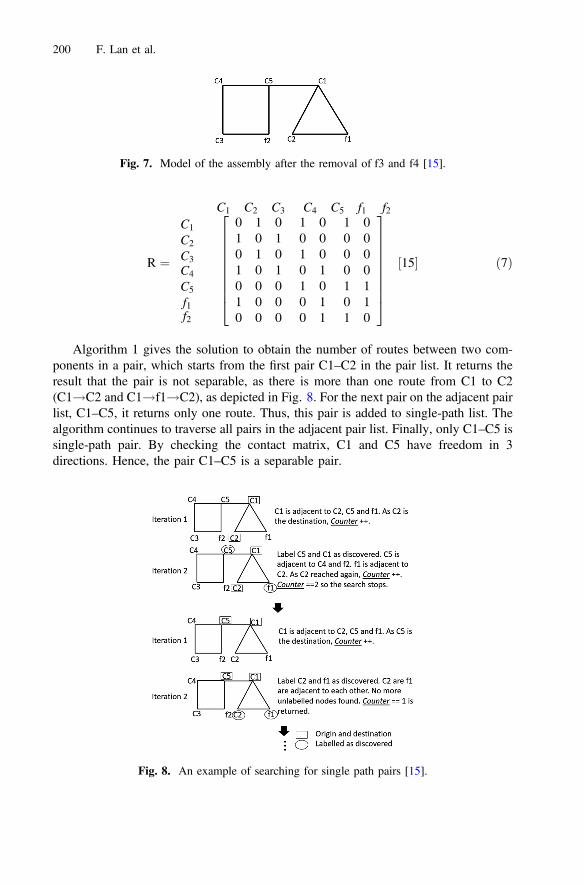
Algorithm 1 gives the solution to obtain the number of routes between two com-ponents in a pair, which starts from the first pair C1–C2 in the pair list. It returns theresult that the pair is not separable, as there is more than one route from C1 to C2(C1!C2 and C1!f1!C2), as depicted in Fig. 8. For the next pair on the adjacent pairlist, C1–C5, it returns only one route. Thus, this pair is added to single-path list. Thealgorithm continues to traverse all pairs in the adjacent pair list. Finally, only C1–C5 issingle-path pair. By checking the contact matrix, C1 and C5 have freedom in 3directions. Hence, the pair C1–C5 is a separable pair.
Fig. 7. Model of the assembly after the removal of f3 and f4 [15].
Fig. 8. An example of searching for single path pairs [15].
200 F. Lan et al.

It indicates that the separation of C1 and C5 would result in two subassemblies:C1–C2–f1 and C3–C4–C5–f2. For each subassembly, f1 and f2 are removablerespectively. The disassembly operations can carry on by applying conventionalsequential disassembly planning methods.
4 Set and Closure: Mathematical Representation
The section first introduces new mathematical tools, set and unary operator, to repre-sent a product and describe its space interference relations. The next part explains thedefinitions of closure which is used to detect subassemblies. They build the foundationof divide-and-conquer strategy.
4.1 Set
The Set of an AssemblyAn assembly of a product can be represented by a set A, which is a collection of thecomponents of the products. Each component Ei i ¼ 1; 2; 3; . . .nð Þ, the element of theset A, cannot be disassembled into smaller components (Eq. 8).
A ¼ E1;E2; . . .;Enf g ð8Þ
The Relation of Components in a SetSpace interferences of components in a set A can be described by using an interferencematrix I [5]. For example, the 2-dimensional space relation of a product in Fig. 9 canbe described in Eq. 9.
I ¼E1 E2 E3
E1E2E3
0000 1110 11101101 0000 00101101 0001 0000
24
35 ð9Þ
Fig. 9. An example to show the use of an interference matrix to describe the 2-dimensionalspace relations of a product.
Interlocking Problem in Automatic Disassembly Planning 201

The Interference Operator of a SetSet A and the interference matrix I describe the attributes of an assembly. For a setA ¼ E1;E2; . . .;Enf g and its interference matrix I, a unary operator Ud Eið Þ Ei 2 Að Þcan obtain the elements which have interference with Ei in direction d(d 2 xþ ; x�; yþ ; y�; zþ ; z�f g).
8Ei 2 A;Ud Eið Þ ¼ Eu;Ev; . . .;Ewf g�A; 1� u; v;w� n ð10Þ
Referring to Eq. 9 as an example, an unary operator can be used to find the elementswhich have space interference with E2 along x+ direction. The result (Eq. 11) indicatesthat E1f g has a space interference with E2 in x+ direction.
E2xþ ¼ E1 E2 E3
½1 0 0� ð11Þ
4.2 Subassembly and Closure
A subassembly is a collection of components that can be disassembled along a certaindirection d without affecting other components. For a given direction d, elements in asubassembly have interferences with one another, but they have no interferences withelements outside the subassembly. In other words, if an element has a space interfer-ence with another element, they both belong to the same subassembly (Eq. 12).
8Ei 2 S;Ud Eið Þ ¼ Eu;Ev; . . .;Ew� ��S ð12Þ
Where S ¼ Eu;Ev; . . .;Ewf g�A; 1� u; v;w� n. The subset S is defined to beclosed under the operator Ud in d direction, if the results of the operation on anyelement in S also belongs to S. Such feature is also called a closure. A closure indicatesthat the elements in the subset do not have interference with components outside thesubset, which is a sign that the subset builds a subassembly that can be removed indirection d.
Also, the subset S in a set A is equivalent to an element in A. The space interferenceoperator can be subjected to the subset S, too. For example, S�A;A ¼E1;E2;E3;E4; . . .;Enf g; S ¼ E1;E2;E3f g, then,
A ¼ S;E4; . . .;Enf g ð13Þ
The divide-and-conquer strategy to be presented in Sect. 5 is based on the detectionof subassemblies through the detection of closure in a set.
202 F. Lan et al.

5 Divide-and-Conquer Disassembly Strategy
The strategy is to divide a product into subassemblies iteratively until all subassembliesbecome individual components which cannot be divided anymore. This method allowsall subassemblies to be identified automatically during a disassembly planning, andhence the interlocking problem does not exist.
5.1 Subassembly Search Process
The search for subassemblies can use the algorithm given in Fig. 10. For example,referring to Fig. 11, after the disassembly of f3 and f4, the assembly is shown as inEq. 14 and the space interference relation is given in Eq. 15.
Fig. 10. Subassembly search process
Fig. 11. An assembly example after the disassembly of f3 and f4 (refer to Fig. 1).
Interlocking Problem in Automatic Disassembly Planning 203

A ¼ C1;C2;C3;C4;C5; f 1; f 2f g ð14Þ
ð15Þ
Identification of a subassembly starts with initialising a target subset S1 to be anempty set /. The subassembly search process adds the first element C1 to the subset S1,and hence S1 ¼ C1f g. Subject the interference operator to C1 along y+ direction toobtain:
Uyþ C1ð Þ ¼ f 1f g ð16Þ
The result f 1f g does not duplicate with the elements in S1, and thus f 1 is added toS1
S1 ¼ C1; f 1f g ð17Þ
Subject the interference operator to the new element f 1 again and yield:
Uyþ f 1ð Þ ¼ C1;C2f g ð18Þ
The new element C2 is added to S1 as in Eq. 19.
S1 ¼ C1; f 1;C2f g ð19Þ
Subject the operator to C2 and yield
Uyþ C2ð Þ ¼ C1; f 1f g�S1 ð20Þ
As C1and f 1 are already in S1, the result indicates that the current subset S1 isclosed.
S1�A; 8Ei 2 S1;Uyþ Eið Þ�S ð21Þ
Hence, the set A can be re-written and contain two elements: subset S1 and itscomplement CAS1.
204 F. Lan et al.

A ¼ S1;CAS1f g ð22Þ
Where CAS1 ¼ C3;C4;C5; f 2f g. The next step is to identify subassemblies in CAS1starting from the first element C3. Because the previous subset S1 can be disassembledalong y+ direction, the new search direction is y−.
Similarly, a subset S2 is initialised to be empty: S2 ¼ /, and the first element C3 isadded to S2. Hence, S2 ¼ C3f g.
Uy� C3ð Þ ¼ C4;C5; f 2f g ð23Þ
C4;C5; f 2 do not exist in S2 and are added.
S2 ¼ C3;C4;C5; f 2f g ¼ CAS1 ð24Þ
The subset S2 is equal to CAS1, which means the second subset has been found.The space interference of the rest of the elements are checked below:
Uy� C4ð Þ ¼ C5f g�S2 ð25Þ
Uy� C5ð Þ ¼ f 2f g�S2 ð26Þ
Uy� f 2ð Þ ¼ C3;C5f g�S2 ð27Þ
Hence, the subset S2 is closed under the interference operator. All the elementshave been traversed, which means
A ¼ S1; S2f g ð28Þ
5.2 Procedure of Divide-and-Conquer Strategy
This strategy analyses elements in set A in a hierarchical way following a proceduregiven in Fig. 13. The first operation is to divide A into subassemblies (Eq. 29)
A ¼ S1; S2; S3; . . .; Suf g ð29Þ
For each Si in A ¼ S1;S2; S3; . . .; Suf g, divide the subset Si into several sub-assemblies again, yields:
Si ¼ Si1; Si2; . . .; Siwf g ð30Þ
Repeat this operation iteratively, until all the subassemblies are components whichcannot be divided anymore. A diagram showing the hierarchy of the disassemblysequences is shown below.
Interlocking Problem in Automatic Disassembly Planning 205

For example, if there is a set A (Eq. 31) and its undisclosed hierarchy is in Fig. 14,the first step of using divide-and-conquer disassembly strategy is to divide A intosubsets, yielding Eqs. 32 and 33.
A ¼ E1;E2; . . .;E10f g ð31Þ
Fig. 12. Procedure of divide and conquer disassembly strategy.
Fig. 13. Hierarchy of disassembly sequences of a product.
Fig. 14. The hierarchy of the disassembly sequences.
206 F. Lan et al.

A ¼ S1; S2; S3; S4f g ð32Þ
S1 ¼ E1f gS2 ¼ E2;E3f gS3 ¼ E4;E5;E6f gS4 ¼ E7;E8;E9;E10f g
8>><>>:
ð33Þ
After generating the first layer of disassembly sequences as in Eq. 33, each subsetis checked. S1 has already been an element so the operation stops. S2, S3, and S4 can befurther divided.
S2 is divided into two subsets:
S2 ¼ S5; S6f g; S5 ¼ E2f gS6 ¼ E3f g
�ð34Þ
S5 and S6 cannot longer be divided.S3 and S4 are divided into subsets below:
S3 ¼ S7; S8f g; S7 ¼ E4;E5f gS8 ¼ E6f g
�ð35Þ
S4 ¼ S9; S10f g; S9 ¼ E7;E8f gS10 ¼ E9;E10f g
�ð36Þ
S7; S9 and S10 can be divided below:
S7 ¼ S11; S12f g; S11 ¼ E4f gS12 ¼ E5f g
�
S9 ¼ S13; S14f g; S13 ¼ E7f gS14 ¼ E8f g
�
S10 ¼ S15; S16f g; S15 ¼ E9f gS16 ¼ E10f g
� ð37Þ
Then, all the subsets contain only an element and the disassembly planning isfinished.
6 Case Study
This section demonstrates a case study of the disassembly of a piston used in a 4-strokeengine, as shown in Fig. 15, by using both ‘separable pairs’ method and divide-and-conquer strategy. B–C1–C2–D is an interlocked structure. Disassembly would requirebuilding two subassemblies: B–C1 and C2–D, so that C1 can be removed from B, andC2 can be taken away from D.
Interlocking Problem in Automatic Disassembly Planning 207

6.1 ‘Separable Pairs’ Method
The sequential disassembly plan as shown in Table 1 is obtained by using the con-ventional sequential disassembly method [4, 5] based on the space interference matrix(Appendix). As shown in Table 1, there is no removable part identified at iteration 7,and parts B, C1–2 and D are interlocked. The methods presented in Sect. 3 is used tofind a separable pair to divide the interlocking structure into subassemblies for normaldisassembly operations.
Fig. 15. Parts in a piston [15].
Table 1. Sequential disassembly plan generated using the method by Jin et al. [15].
Iteration Removable parts Remaining parts
1 A1-111110 B, C1–2, D, F, G, H2–5A2-111110E1-110111E2-111011H1-111101
2 F -110011 B, C1–2, D, G, H3–5H2 - 111101
3 H3 - 111101 B, C1–2, D, G, H4–54 H4 - 111101 B, C1–2, D, G, H55 H5 - 111101 B, C1–2, D, G6 G - 111101 B, C1–2, D7 None B, C1–2, D
208 F. Lan et al.

Equations 38 and 39 give the contact matrix and the relation matrix of the inter-locked structure B–C1–C2–D. By using the method presented in Eqs. 3 to 6, threeadjacent components pairs are identified: B–C1, B–D and C2–D. Then, the number ofroutes between two components in each adjacent components pair is calculated basedon Algorithm 1. The results show that all adjacent components pairs are single-pathpairs. However, by checking the contact matrix, only B–D pair is a separable pair asC12 and C43 in Eq. 38 are 111111, indicating that either B–C1 or C2–D has no freedomto separate. The separation of B and D forms two subassemblies, B–C1 and C2–D.Thus, the conventional sequential disassembly methods can carry on.
ð38Þ
R ¼
B C1 C2 DBC1C2D
0 11 0
0 10 0
0 01 0
0 11 0
264
375 15½ � ð39Þ
6.2 Divide-and-Conquer Strategy
By using the divide-and-conquer disassembly strategy proposed, the hierarchy of thepiston example can be generated as in Fig. 16. The disassembly sequences are gen-erated, given in Tables 2, 3 and 4 by using the space interference matrix (Appendix).
Fig. 16. Hierarchy analysis of piston example.
Interlocking Problem in Automatic Disassembly Planning 209

When it comes to step 7, the remaining subassemblies is {B, C1} and {D, C2}.Similarly, the disassembly sequences of these two subassemblies generated by divide-and-conquer strategy are shown in Tables 3 and 4. The interlocking problem does notexist using this method.
Table 2. Divide-and-conquer disassembly sequences of the example product.
Iteration Subassemblies Minimum units Remaining subassemblies
1 {A1},{A2},{E1},{E2},{H1},{B, C1–2, D, F, G, H2–5}
{A1},{A2},{E1},{E2},{H1}
{B, C1–2, D, F, G, H2–5}
2 {F},{H2},{B, C1–2, D, G, H3–5}
{F},{H2}
{B, C1–2, D, G, H3–5}
3 {H3},{B, C1–2, D, G, H4–5}
{H3} {B, C1–2, D, G, H4–5}
4 {H4},{B, C1–2, D, G, H5}
{H4} {B, C1–2, D, G, H5}
5 {H5},{B, C1–2, D, G}
{H5} {B, C1–2, D, G}
6 {G},{B, C1–2, D}
{G} {B, C1–2, D}
7 {B, C1},{D, C2}
/ {B, C1},{D, C2}
Table 3. Disassembly sequences of the subassembly {B, C1}.
Iteration Subassemblies Minimum units Remaining subassemblies8 {B},
{C1}{B},{C1}
/
Table 4. Disassembly sequences of the subassembly {D, C2}.
Iteration Subassemblies Minimum units Remaining subassemblies8 {D},
{C2}{D},{C2}
/
210 F. Lan et al.

7 Conclusion
Machine understanding of the structure of an assembly in three-dimensional space is anenabler of autonomous disassembly planning. Conventionally, due to the complexity ofspatial information, many disassembly planning methods are not suitable for thosecontaining interlocked components.
This paper presents two methods to deal with the interlocking problem. They aredesigned to work for all subassemblies containing interlocking components and theireffectiveness was demonstrated with a case study. One work is based on the search forseparable pairs, which can be used to identify subassemblies during a sequential dis-assembly planning. The other solution is based on a divide-and-conquer strategy toreplace the conventional sequential disassembly methods. It plans disassemblysequence through the detection of subassemblies instead of removable individualcomponents so that interlocked components can be detected automatically in eachinteraction, and thus interlocking problems can be avoided.
Acknowledgement. This research was supported by the EPSRC (Grant No. EP/N018524/1) andthe National Science Foundation of China (Grant No. 51775399).
Interlocking Problem in Automatic Disassembly Planning 211

Appendix
Space interference matrix 15:
212 F. Lan et al.

References
1. Barwood M, Li J, Pringle T, Rahimifard S (2015) Utilisation of reconfigurable recyclingsystems for improved material recovery from e-waste. Procedia CIRP 29:746–751. https://doi.org/10.1016/j.procir.2015.02.071
2. Gil P, Pomares J, Puente SVT, Diaz C, Candelas F, Torres F (2007) Flexible multi-sensorialsystem for automatic disassembly using cooperative robots. Int J Comput Integr Manuf 20(8):757–772. https://doi.org/10.1080/09511920601143169
3. Ji C, Pham DT, Su S, Huang J, Wang Y (2017) AUTOREMAN – D.1.1 - List of genericdisassembly task categories. Technical report, Autonomous Remanufacturing Laboratory,The University of Birmingham
4. Jin G, Li W, Wang S, Gao S (2015) A systematic selective disassembly approach for wasteelectrical and electronic equipment with case study on liquid crystal display televisions. ProcInst Mech Eng Part B J Eng Manuf 231:2261–2278. https://doi.org/10.1177/0954405415575476
5. Jin GQ, Li WD, Xia K (2013) Disassembly matrix for liquid crystal displays televisions.Procedia CIRP 11:357–362. https://doi.org/10.1016/j.procir.2013.07.015
6. Johnson MR, McCarthy IP (2014) Product recovery decisions within the context of extendedproducer responsibility. J Eng Tech Manag 34:9–28. https://doi.org/10.1016/j.jengtecman.2013.11.002
7. Kopacek P, Kronreif G (1996) Semi-automated robotic disassembling of personalcomputers. In: EFTA 1996 - IEEE conference on emerging technologies and factoryautomation, vol 2, pp 567–572. IEEE. https://doi.org/10.1109/ETFA.1996.573938
8. Li JR, Khoo LP, Tor SB (2002) A novel representation scheme for disassembly sequenceplanning. Int J Adv Manuf Technol 20(8):621–630. https://doi.org/10.1007/s001700200199
9. Smith S, Chen W-H (2009) Rule-based recursive selective disassembly sequence planningfor green design. Springer, London, pp 291–302. https://doi.org/10.1007/978-1-84882-762-2_27
10. Smith S, Hung P-Y (2015) A novel selective parallel disassembly planning method for greendesign. J Eng Des 26(10–12):283–301. https://doi.org/10.1080/09544828.2015.1045841
11. Smith S, Smith G, Chen W-H (2012) Disassembly sequence structure graphs: an optimalapproach for multiple-target selective disassembly sequence planning. Adv Eng Inform 26(2):306–316. https://doi.org/10.1016/j.aei.2011.11.003
12. Tao F, Bi L, Zuo Y, Nee AYC (2017) Partial/parallel disassembly sequence planning forcomplex products. J Manuf Sci Eng 140(1):011016. https://doi.org/10.1115/1.4037608
13. Torres F, Puente ST, Aracil R (2003) Disassembly planning based on precedence relationsamong assemblies. Int J Adv Manuf Technol 21(5):317–327. https://doi.org/10.1007/s001700300037
14. Vongbunyong S, Chen WH (2015) Disassembly automation. Springer, Cham. https://doi.org/10.1007/978-3-319-15183-0
15. Wang Y, Lan F, Pham D, Liu J, Huang, J, Ji C, Su S, Xu W, Liu Q, Zhou Z (2018)Automatic detection of subassemblies for disassembly sequence planning. In: Proceedings ofthe 15th international conference on informatics in control, automation and robotics - volume1: ICINCO, pp 94–100. https://doi.org/10.5220/0006906601040110. ISBN 978-989-758-321-6
16. Zhao S, Li Y (2010) Disassembly sequence decision making for products recycling andremanufacturing systems. In: 2010 International symposium on computational intelligenceand design, pp 44–48). IEEE. https://doi.org/10.1109/ISCID.2010.19
Interlocking Problem in Automatic Disassembly Planning 213