INTERIM TECHNOLOGY PERFORMANCE REPORT - … · INTERIM TECHNOLOGY PERFORMANCE REPORT DOE Award...
29
© 2013 Long Island Power Authority INTERIM TECHNOLOGY PERFORMANCE REPORT DOE Award Number: DE-OE0000220 Name of Recipient: Long Island Power Authority Project Title: Long Island Smart Energy Corridor Project Director/ Principal Investigator: Ming Mui Long Island Power Authority DUNS: 133551270 333 Earle Ovington Boulevard Suite 403 Uniondale, New York 11553-3645 516.719.9876 www.lipower.org Date Submitted: June 30, 2013 SUBMITTED TO: U.S DEPARTMENT OF ENERGY, OFFICE OF ELECTRICITY DELIVERY AND ENERGY RELIABILITY NATIONAL ENERGY TECHNOLOGY LABORATORY
Transcript of INTERIM TECHNOLOGY PERFORMANCE REPORT - … · INTERIM TECHNOLOGY PERFORMANCE REPORT DOE Award...

© 2013 Long Island Power Authority
INTERIM TECHNOLOGY PERFORMANCE REPORT
DOE Award Number: DE-OE0000220 Name of Recipient: Long Island Power Authority Project Title: Long Island Smart Energy Corridor Project Director/ Principal Investigator: Ming Mui Long Island Power Authority DUNS: 133551270 333 Earle Ovington Boulevard Suite 403 Uniondale, New York 11553-3645 516.719.9876 www.lipower.org Date Submitted: June 30, 2013
SUBMITTED TO: U.S DEPARTMENT OF ENERGY, OFFICE OF ELECTRICITY DELIVERY AND ENERGY RELIABILITY NATIONAL ENERGY TECHNOLOGY LABORATORY

RECIPIENT PROJECT TITLE DOE AWARD No. DATE OF REPORT REVISION HISTORY Long Island Power Authority Long Island Smart Energy Corridor DE-OE0000220 6/30/2013 Rev 0
INTERIM TECHNOLOGY PERFORMANCE REPORT Page i
TABLE OF CONTENTS
Scope ............................................................................................................................................. 1
Project Abstract .................................................................................................................................................... 1 Recipient Team Overview .................................................................................................................................. 2
Long Island Power Authority ...................................................................................................................... 2 Farmingdale State College ............................................................................................................................ 3 SUNY Stony Brook......................................................................................................................................... 3
Project Overview .................................................................................................................................................. 4 Technologies and Systems to be Demonstrated ............................................................................................ 6
AMI Assets ...................................................................................................................................................... 6 Customer Systems Assets ............................................................................................................................. 7 Electric Distribution and Substation Assets ............................................................................................... 8
DOE Smart Grid Functions and Energy Storage Apllications .................................................................... 8 Smart Grid Functions .................................................................................................................................... 8 Energy Storage Applications ........................................................................................................................ 9
Grid or Non‐Grid Connected Benefits ............................................................................................................ 9 Technical Approach for Achieving Interoperability and Cyber Security ............................................... 10 Interactions with Project Stakeholders .......................................................................................................... 12
AMI Testing Group Customer Outreach .................................................................................................. 14 Ongoing Customer Engagement ............................................................................................................... 15
Technical Approach ................................................................................................................. 17
Project Plan ......................................................................................................................................................... 17 Steps to Achieve Effective Deployment .................................................................................................... 17 Proposed Test Plan ...................................................................................................................................... 22
Data Collection and Benefits Analysis .......................................................................................................... 23
Results ........................................................................................................................................ 24
Operation of Smart Grid Technologies and Systems ................................................................................. 24 Energy Storage System Performance Parameters ........................................................................................ 24 Impact Metrics and Benefits Analysis ........................................................................................................... 24 Stakeholder Feedback ....................................................................................................................................... 24
Conclusions ............................................................................................................................... 25
Projections of Demonstration and Commercial-scale System Performance........................................... 25 Lessons Learned and Best Practices ................................................................................................................ 25
Contacts ...................................................................................................................................... 26
Appendices ................................................................................................................................ 27

LIPA – SGDP 110 Smart Corridor 6/30/2013 Interim Technology Performance Report Regional Demonstration
Page 1
SCOPE
PROJECT ABSTRACT
The Long Island Power Authority (“LIPA”) has teamed with Stony Brook University (“Stony Brook” or “SBU”) and Farmingdale State College (“Farmingdale” or “FSC”), two branches of the State University of New York (“SUNY”), to create a “Smart Energy Corridor.” The project, located along the Route 110 business corridor on Long Island, New York, is demonstrating the integration of a suite of Smart Grid technologies from substations to end-use loads. The Smart Energy Corridor Project includes the following key features:
TECHNOLOGY: Demonstration of a full range of smart energy technologies, including substations and distribution feeder automation, fiber and radio communications backbone, advanced metering infrastructure (“AMI”), meter data management (“MDM”) system (which LIPA will implement outside of this project), field tools automation, outage management system, customer-level energy management including automated energy management systems, and integration with distributed generation and plug-in hybrid electric vehicles.
MARKETING: A rigorous market test to identify the optimal combination of features to stimulate customer adoption and acceptance of Smart Grid technologies including alternative time-of-use and dynamic pricing plans, varying levels of information and analytical support, web-enabled data visualization options, and enhanced customer outreach efforts.
CYBER SECURITY: Testing of cyber security vulnerabilities in Smart Grid hardware, network, and application layers in order to develop policies, procedures, and technical controls to prevent or foil cyber-attacks and to harden the Smart Grid infrastructure.
RELIABILITY: Leveraging new Smart Grid-enabled data to increase system efficiency and reliability by developing enhanced load forecasting, phase balancing, and voltage control techniques designed to work hand-in-hand with the Smart Grid technologies.
OUTREACH: Public outreach and educational initiatives that are linked directly to the demonstration of Smart Grid technologies, tools, techniques, and system configurations. This includes creation of full-scale operating models demonstrating application of Smart Grid technologies in business and residential settings. These initiatives will increase understanding and acceptance of Smart Grid transformation by the general public, business, industry, and municipalities in the Long Island and greater New York region.
JOB CREATION: Training for the Smart Grid and clean energy jobs of the future at both Farmingdale and Stony Brook. Stony Brook will focus its “Cradle to Fortune 500” suite of economic development resources on the opportunities emerging from the project, helping to create new technologies, new businesses, and new jobs.
With the full support and encouragement of the New York State Governor, the Smart Energy Corridor is (1) validating Smart Grid technologies; (2) quantifying Smart Grid costs and benefits; and (3) validating Smart Grid applications at a scale that can be readily adapted and replicated in individual homes and businesses. On August 25, 2010 Governor David Paterson kicked off the New York State Smart Grid
LIPA – SGDP 110 Smart Corridor 6/30/2013 Interim Technology Performance Report Regional Demonstration
Page 2
Consortium to foster the development and deployment of new technology aimed at reducing the cost of electricity while increasing reliability. The favorable climate for Smart Grid in New York enhances the likelihood of success for the Smart Energy Corridor Project. The Smart Energy Corridor Project goes well beyond DOE’s goals for demonstration of Smart Grid technologies. Its community and economic development aspects will reach a widespread audience to further the public understanding and acceptance of Smart Grid technologies and their benefits.
RECIPIENT TEAM OVERVIEW
The Long Island Power Authority (“LIPA”) is the second largest public power utility in the United States, in terms of revenue. LIPA has teamed with two branches of the State University of New York (“SUNY”) through The Research Foundation of SUNY Stony Brook University (“Stony Brook”) and The Foundation of SUNY on Behalf of Farmingdale State College (“Farmingdale”) to deliver a demonstration of Smart Grid technology and benefits that have specific applicability to the greater New York and Northeast region, as well as significant benefits to the industry as a whole. LONG ISLAND POWER AUTHORITY The LIPA Service Area encompasses the bulk of Long Island in New York State, and is comprised of Nassau and Suffolk Counties and the Rockaway Peninsula of Queens County, an area of approximately 1,230 square miles, excluding areas served by three municipal utilities: the villages of Freeport, Greenport, and Rockville Centre. Suffolk County is the easternmost county within the Service Area and covers an area of approximately 911 square miles, followed by Nassau County with a 287 square mile area, and the Rockaway Peninsula with an area of approximately 32 square miles. The Service Area is bounded by the Atlantic Ocean on the south and east, by the Long Island Sound on the north, and by portions of New York City on the west.
LIPA’s Service Territory
Total number of customers:
Residential 1,124,170
Commercial 228,554
Peak load:
Summer 5,825 MW
Winter 3,759 MW
Total MWh sales (in a 24-hour period includes: residential & commercial and line losses)
113,951 MWH

LIPA – SGDP 110 Smart Corridor 6/30/2013 Interim Technology Performance Report Regional Demonstration
Page 3
Total number of substations providing distribution load 150
Total number of distribution feeders 903
Total miles of distribution line 13,715
Table 1 - LIPA’s Service Territory
FARMINGDALE STATE COLLEGE Farmingdale State College is the largest College of Applied Science and Technology in the 64-institution SUNY system. Farmingdale is located in the Route 110 Corridor. It offers a state-funded, campus-based business incubation facility, located at the Broadhollow Bioscience Park. The College’s four Schools, Engineering Technology, Arts and Sciences, Health Sciences, and Business, offer 25 baccalaureate degree programs and 10 associate degree programs, enrolling over 6,800 undergraduate students. The Engineering School offers bachelor degrees and associate degrees in many disciplines including Aeronautical Science, Architectural Engineering Technology, Construction Management Engineering Technology, Computer Engineering Technology, Electrical Engineering Technology, Mechanical Engineering Technology, Manufacturing Engineering Technology, Facility Management, Software Technology, and Automotive Technology. The College – and especially the School of Engineering Technology – has long been recognized as a leader in energy management and sustainability. The College established the first accredited Solar Energy Center in the Northeast in 2000, and Farmingdale State College is now creating a Green Building Institute that, in partnership with industry, municipalities, and educational institutions on Long Island, will promote sustainability through education and research in areas such as solar and wind energy, architecture and building design, green roofs and sustainable gardens, and energy efficiency audits and monitoring. Farmingdale State College is one of LIPA’s largest commercial customers in the Route 110 corridor. As part of the Smart Energy Corridor Project, the project will install AMI meters on the Residential Demonstration House and be offered the opportunity to participate in the new TOU rate. SUNY STONY BROOK
Stony Brook is also located within LIPA’s service territory. Stony Brook is SUNY's flagship research campus and collaborates with Brookhaven National Laboratory, which it now co-manages with Battelle for the US Department of Energy. Its growing research capacity is exemplified by its newest research facilities, the recently opened Advanced Energy Research and Technology Center (“AERTC”) and the New York State Center of Excellence in Wireless and Information Technology (“CEWIT”). The AERTC's mission is to deliver IT and nano-science and technology-based means of accelerating the transfer of alternative energy technologies from the laboratory to the marketplace. CEWIT is one of only two wireless and IT centers in the nation and a handful around the world. CEWIT's affiliated laboratories include the Center for Cyber Security, a National Security Agency-designated Center of Excellence, and

LIPA – SGDP 110 Smart Corridor 6/30/2013 Interim Technology Performance Report Regional Demonstration
Page 4
its affiliated labs including the Security, Programming Languages and Theory (“SPLAT”) Lab, specializing in Software Security, System and Network Security and Cryptography; the Network Security and Applied Cryptography Lab, the File Systems and Storage Lab. Another major CEWIT affiliate is the Center for Visual Computing. Stony Brook's management development and workforce training programs, offered through the College of Business, the School for Professional Development and the College of Engineering and Applied Sciences, assists 2,000 professionals a year. These programs range from the Executive MBA program through specialized master’s degree programs in business and engineering specialties, graduate certificate programs in management and technical areas, and non-credit programs, workshops, seminars, and distance learning offerings across information technology, engineering and basic and advanced management topics, customizable based on a needs assessment climate survey and deliverable on-campus or on-site. As SUNY's most successful technology transfer and economic development campus, Stony Brook will leverage its existing, comprehensive suite of "Cradle to Fortune 500" economic development programs to commercialize new technologies emerging from this project to strengthen established companies, created new ventures and retain and create new quality jobs.
PROJECT OVERVIEW
The LIPA Smart Grid Demonstration Project includes the installation of AMI, distribution automation and substation automation, as well as the installation of load control devices (approximately 100) and customer automation systems (up to 5). The AMI deployment will consist of the installation of 1,488 smart meters at residential locations and approximately 850 smart meters at commercial locations. The distribution automation work will involve the deployment of 24 smart switches on more than 18 circuits across three substations, as well as the installation of 51 automated capacitor bank controllers. The substation automation work will involve upgrading the five existing RTUs and installing 26 new digital meters across the three substations. The Long Island Smart Energy Corridor Project has seven objectives:
1. Demonstrate and validate how Smart Grid technologies can reduce customer costs for electricity and decrease peak loads and system demand;
2. Demonstrate how Smart Grid technologies can enhance reliability by reducing the frequency and duration of outages;
3. Demonstrate how distributed generation can be integrated with Smart Grid technologies to reduce system demand and defer utility investments;
4. Anticipate and address emerging cyber security concerns with Smart Grid technologies (especially AMI), while leveraging the potential for enhanced data collection and analysis enabled by smart devices;
5. Facilitate the development and commercialization of new Smart Grid technologies and tools;

LIPA – SGDP 110 Smart Corridor 6/30/2013 Interim Technology Performance Report Regional Demonstration
Page 5
6. Develop relevant curricula to train the workforce that will be needed for significant expansion of Smart Grid, renewable and photovoltaic hybrid electric vehicle (PHEV) technology deployment; and
7. Engage customers by performing outreach and informational activities, and by providing a platform for customer understanding, acceptance and use of Smart Grid technologies and dynamic pricing to reduce customer costs for energy and to reduce demand during system peak.
The Long Island Smart Energy Corridor Project will integrate advanced metering infrastructure (AMI) technology with the distribution automation system, implementation of advanced substation automation technologies, and other features to demonstrate how customers and utilities can work together to give residential, industrial and commercial customers more information and choices, enabling them to reduce their energy costs while reducing peak demand and increasing the utility’s ability to identify and respond to outages on an expedited basis. AMI will be installed at approximately 2,338 customer locations, of which 1,488 will be residential. A key component of this demonstration project is to evaluate the impact of a range of variables on customer behavior and consumption, including alternate tariff structures, provision of varying levels of information and analytical tools, a range of outreach and educational support and energy automation for a sample of participating customers. In addition, the Smart Energy Corridor will include demonstrations of how distributed generation (in this case, wind and solar at Farmingdale State College) can be integrated into a local distribution network with AMI technologies to serve customers while maintaining reliability. The Farmingdale State College portion of the project will include “live” residential and commercial models showing how intelligent devices can enable customers to understand and control their usage and respond to price signals, as well as integrating distributed renewable energy. Farmingdale will also develop a curriculum and training materials relating to AMI infrastructure, integration of distributed renewable generation and PHEV systems in order to provide for a trained workforce in the future. These items will not be discussed in Technology Performance Reports for the project since these items are largely for educational and public outreach purposes. However, generation data will be collected and reported as will attendance at training sessions. Stony Brook University will utilize its existing center of excellence relating to internet and computer security to provide research into cyber security as it relates to intelligent devices used for Smart Grid applications, focusing on AMI. In addition, Stony Brook will develop mechanisms to leverage the data available from smarter devices as part of a learning culture of continuous improvement. Stony Brook University will foster commercialization of new smart grid technologies and applications, with the intent of furthering economic development and job creation. Both Stony Brook and Farmingdale will engage in extensive public education and outreach.

LIPA – SGDP 110 Smart Corridor 6/30/2013 Interim Technology Performance Report Regional Demonstration
Page 6
TECHNOLOGIES AND SYSTEMS TO BE DEMONSTRATED
LIPA is deploying AMI, distribution automation and substation automation, as described below.1 In addition, Farmingdale State College will be installing small-scale wind generation (three (3) nominal 2.4 kW grid-connected monopole wind turbines), as well as a solar parking lot that will include PV as well as charging stations (100 kW solar panels over 42 parking spaces which includes 10 double pedestal EV charging stations). Farmingdale will also include a fuel cell and additional solar generation in its model to demonstrate residential smart grid applications. As noted above, the primary purpose of these installations is education and training, although the generation will be tracked and reported. AMI ASSETS 1,488 residential smart meters and 848 commercial meters have been deployed to date, with 2 additional commercial meters expected to be installed at customer sites by September 1, 2013. The smart meters will support the recording of 5-, 15-, 30-, and 60-minute interval lengths, 4 channels of data capable of measuring reactive energy quantities, net metering, time of use, perpetual calendar, interval demand values, kVA recording, power factor recording, outage detection reporting, power quality monitoring, and tamper detection. Additionally, a small sample of meters will have remote connection/disconnection capability that allows control of the switch status. The AMI system selected will utilize an RF mesh network with wireless carrier backhaul or fiber-optic to the three substations. The RF mesh network will be supplemented by wireless carrier enable meters for locations that are not near any AMI routers and collectors as the technology evolves. A field inventory system that was originally contemplated will not be installed. Initial deployment of AMI will use a Vendor Hosted AMI Head-End that will use a Cellular Backhaul (Verizon (EVDO)) that will communicate from the AMI Collector to AMI Hosted Head-End system. This AMI Head-End System may be transitioned to a LIPA facility. In that case, the Non-SGDP Fiber Communications Project will enable communications from the collectors to the Substation and then back to the AMI Head-End. The primary functions of the head end system include performing scheduled reads on billing cycle, provide outage information, detect tampering and provide various reporting tools. LIPA has implemented an e-Meter Meter Data Management System outside of the Smart Grid Demonstration Project. The e-Meter system will perform auto-provisioning, data validation, estimation, and create billing determinants.
1 The AMI and pilot OMS/DMS Integration (project simulation) is under review as a result of LIPA’s decision to deploy a full-
scale OMS/DMS outside of the project and a more recent decision to change OMS vendors and defer a full DMS deployment. In
any case, because this portion of the project was a simulation, none of the impact metrics to be reported relate to it.

LIPA – SGDP 110 Smart Corridor 6/30/2013 Interim Technology Performance Report Regional Demonstration
Page 7
Asset Summary:
1488 residential meters
850 commercial meters (809 installed to date)
[AMI and pilot OMS/DMS Integration (project simulation) – Under review.] Installed costs (to date):
$825,808 Note: 50% of the installed costs were funded by the DOE
CUSTOMER SYSTEMS ASSETS LIPA plans to deploy smart meters that can interface with customer communication networks for the eventual adoption of home area networks (“HAN”) by customers (in other words, LIPA will not purchase or offer a HAN as part of this project). While LIPA anticipates some customers will eventually purchase smart appliances, LIPA does not intend to deploy any of these products as part of this project or expect to know when customers purchase them. LIPA will provide a web-portal that will be available for all customers receiving AMI meters, excluding the control and test groups. Customers can enroll in the web-portal services and receive information related to energy usage, including consumption and cost data, and recommendations for better ways to manage their energy usage. LIPA will also deploy a mobile application for customer use. LIPA intends to deploy Direct Load Control (DLC) technology to 100 residential and 2 commercial customers as part of this project. Residential customers will have thermostats installed to control each zone in their house, as well as load control devices, as applicable, on other loads such as pool pumps. In addition, they will each receive two smart plugs. Two different configurations will be tested in the residential program. The first will include data collection and control through an installed “gateway” that will interface with the home devices via ZigBee. The gateway will utilize an internet connection to communicate with the utility. In the second configuration, the meter will replace the gateway and the meter communications system will serve as the communications path to the utility for data and control. Asset Summary:
Web-portal access for all commercial and residential customers (in project test group)
Limited number of In Home Displays (approximately 20), depending on customer preference
Mobile application (project)
Load control devices (approximately 30) Note: This portion of the project has not yet been installed.
Installed costs (to date):
$0

LIPA – SGDP 110 Smart Corridor 6/30/2013 Interim Technology Performance Report Regional Demonstration
Page 8
ELECTRIC DISTRIBUTION AND SUBSTATION ASSETS LIPA is deploying distribution automation and substation automation in the Route 110 Corridor. A pilot scale OMS/DMS system (project simulation) was to be deployed but is currently under review as noted above. Eighteen of the 32 feeders from three substations have been targeted for this project to become “smart feeders,” with additional switches being installed on certain other feeders as well. LIPA intends to enable automatic feeder switching and coordinated voltage management as part of this distribution automation implementation. LIPA expects to be able to improve reliability for customers and reduce distribution line-loses utilizing this new functionality. Asset Summary:
18 overhead switches to circuits fed from three substations, plus supervisory control for the six underground pad mounts monitoring analogs such as voltage, current, and phase angle.
49 two-way capacitor bank controllers over all of the circuits fed from the three substations. (2 remaining to be installed to date).
Upgrades to five substation RTUs to enable an increase in the quantity of data brought back
26 digital meters at substations (four at South Farmingdale and 22 at Ruland Road) Installed costs (to date):
$3,006,566 Note: 50% of the installed costs were funded by the DOE
DOE SMART GRID FUNCTIONS AND ENERGY STORAGE APLLICATIONS
SMART GRID FUNCTIONS
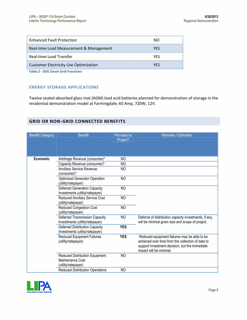
Function Provided by Project
Fault Current Limiting NO Wide Area Monitoring, Visualization, & Control NO Dynamic Capability Rating NO Power Flow Control NO Adaptive Protection NO Automated Feeder Switching YES Automated Islanding and Reconnection NO Automated Voltage & VAR Control YES Diagnosis & Notification of Equipment Condition YES
LIPA – SGDP 110 Smart Corridor 6/30/2013 Interim Technology Performance Report Regional Demonstration
Page 9
Enhanced Fault Protection NO Real-time Load Measurement & Management YES Real-time Load Transfer YES Customer Electricity Use Optimization YES Table 2 - DOE Smart Grid Functions
ENERGY STORAGE APPLICATIONS Twelve sealed absorbed glass mat (AGM) lead acid batteries planned for demonstration of storage in the residential demonstration model at Farmingdale; 60 Amp, 720W, 12V.
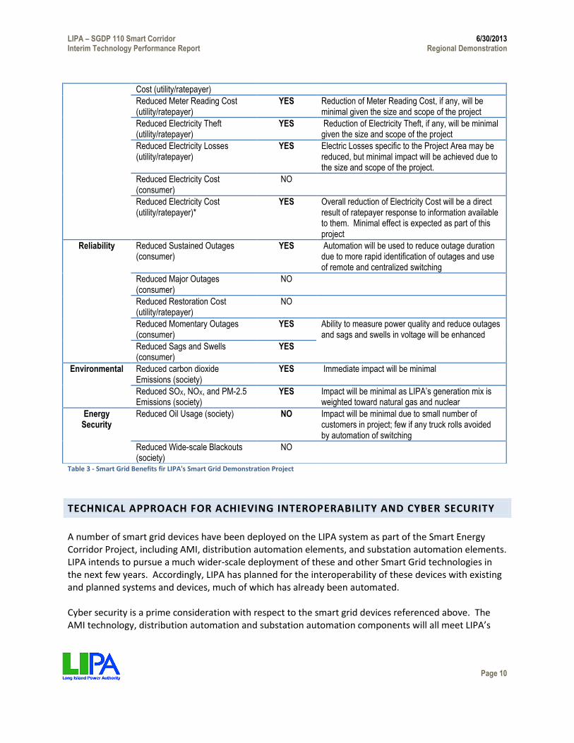
GRID OR NON‐GRID CONNECTED BENEFITS
Benefit Category Benefit Provided by Project?
Remarks / Estimates
Economic Arbitrage Revenue (consumer)* NO
Capacity Revenue (consumer)* NO
Ancillary Service Revenue (consumer)*
NO
Optimized Generator Operation (utility/ratepayer)
NO
Deferred Generation Capacity Investments (utility/ratepayer)
NO
Reduced Ancillary Service Cost (utility/ratepayer)
NO
Reduced Congestion Cost (utility/ratepayer)
NO
Deferred Transmission Capacity Investments (utility/ratepayer)
NO Deferral of distribution capacity investments, if any, will be minimal given size and scope of project.
Deferred Distribution Capacity Investments (utility/ratepayer)
YES
Reduced Equipment Failures (utility/ratepayer)
YES Reduced equipment failures may be able to be achieved over time from the collection of data to support investment decision, but the immediate impact will be minimal.
Reduced Distribution Equipment Maintenance Cost (utility/ratepayer)
NO
Reduced Distribution Operations NO
LIPA – SGDP 110 Smart Corridor 6/30/2013 Interim Technology Performance Report Regional Demonstration
Page 10
Table 3 - Smart Grid Benefits fir LIPA's Smart Grid Demonstration Project
TECHNICAL APPROACH FOR ACHIEVING INTEROPERABILITY AND CYBER SECURITY
A number of smart grid devices have been deployed on the LIPA system as part of the Smart Energy Corridor Project, including AMI, distribution automation elements, and substation automation elements. LIPA intends to pursue a much wider-scale deployment of these and other Smart Grid technologies in the next few years. Accordingly, LIPA has planned for the interoperability of these devices with existing and planned systems and devices, much of which has already been automated. Cyber security is a prime consideration with respect to the smart grid devices referenced above. The AMI technology, distribution automation and substation automation components will all meet LIPA’s
Cost (utility/ratepayer)
Reduced Meter Reading Cost (utility/ratepayer)
YES Reduction of Meter Reading Cost, if any, will be minimal given the size and scope of the project
Reduced Electricity Theft (utility/ratepayer)
YES Reduction of Electricity Theft, if any, will be minimal given the size and scope of the project
Reduced Electricity Losses (utility/ratepayer)
YES Electric Losses specific to the Project Area may be reduced, but minimal impact will be achieved due to the size and scope of the project.
Reduced Electricity Cost (consumer)
NO
Reduced Electricity Cost (utility/ratepayer)*
YES Overall reduction of Electricity Cost will be a direct result of ratepayer response to information available to them. Minimal effect is expected as part of this project
Reliability Reduced Sustained Outages (consumer)
YES Automation will be used to reduce outage duration due to more rapid identification of outages and use of remote and centralized switching
Reduced Major Outages (consumer)
NO
Reduced Restoration Cost (utility/ratepayer)
NO
Reduced Momentary Outages (consumer)
YES Ability to measure power quality and reduce outages and sags and swells in voltage will be enhanced
Reduced Sags and Swells (consumer)
YES
Environmental Reduced carbon dioxide Emissions (society)
YES Immediate impact will be minimal
Reduced SOX, NOX, and PM-2.5 Emissions (society)
YES Impact will be minimal as LIPA’s generation mix is weighted toward natural gas and nuclear
Energy Security
Reduced Oil Usage (society) NO Impact will be minimal due to small number of customers in project; few if any truck rolls avoided by automation of switching
Reduced Wide-scale Blackouts (society)
NO

LIPA – SGDP 110 Smart Corridor 6/30/2013 Interim Technology Performance Report Regional Demonstration
Page 11
minimum cyber security requirements. Stony Brook’s Center for Cyber Security, an NSA-designated Center of Excellence, will evaluate cyber security issues related to the AMI devices being employed as part of this demonstration program and will put forth recommendations to DOE and equipment vendors based on their testing. The National Institute of Standards and Technology (“NIST”) has begun an effort under the Energy Independence and Security Act of 2007 (EISA) to establish a smart grid interoperability framework and has required that new applications for grants comply with such resulting standards after promulgation. The ARRA added a requirement that “projects utilize open protocols and standards (including Internet-based protocols and standards) if available and appropriate.” The LIPA project satisfies these requirements with the existing systems automation that has been done as part of the implementation of a common information model that follows open standards being addressed by NIST. The American National Standards Institute has developed the ANSI C12 series electricity metering standards for use in the US and Canada. Federal, state, and local codes and/or public utility commissions turn ANSI standards into law by requiring their use. The C12 series includes a number of standards, including ANSI C12.22, Protocol Specification for Interfacing to Data Communications Networks. The ANSI C12.22 standards committee consists of utilities, vendors, and consultants. The AMI vendor electricity metering solutions selected satisfy appropriate C12 series standards, including C12.22. The ANSI accredited Standards Development Organization for C12 is the National Electrical Manufacturers Association (NEMA). NEMA is one of four designated stakeholders for smart grid interoperability standards development with NIST in EISA. The software applications that LIPA intends to use, including the AMI management systems, are based on the Open Systems Interconnection (“OSI”) Seven Layer Model of the International Organization for Standardization (“ISO”). The application programming interfaces are open and available for any third party system supplier to integrate with the applications. Each application is capable of running TCP/IP, HTTP, and SOAP protocols and standards. As an early adopter of distribution automation for its electrical system, LIPA has already seen the possibilities and benefits from a Smart Grid. Recognizing this and the future of electric utility operations and customer service in the industry, LIPA began preparing itself for the implementation of Smart Grid several years ago. As a participant in EPRI’s Intelligrid initiative, LIPA had a role in shaping the vision for Smart Grid, and became a major proponent of the adoption of standards for interoperability within the industry. Additionally, LIPA recognized the challenges of interoperability and began making preparations internally and with its service providers to meet those challenges. LIPA has taken a number of actions to establish methodology and standardization requirements to create the framework within which the Smart Grid Demonstration Project will be developed and deployed. Because of the need to assure the success of the Project and the future of LIPA in meeting its customers’ needs with Smart Grid investments, LIPA recognized that a critical component was to create a framework within which interoperability between the multiple domains in an electric system could be maintained. Accordingly, LIPA established a number of requirements to be applied to information systems’ projects that support this initiative including the following:

LIPA – SGDP 110 Smart Corridor 6/30/2013 Interim Technology Performance Report Regional Demonstration
Page 12
Technical Architecture and Approach;
An Enterprise Semantic Model and Approach; and
A System Development Life Cycle and Documentation. As LIPA begins the implementation of its 110 Corridor project, it will be following the guidelines published by the NIST in August and September 2010, NISTIR 7628. These guidelines provide a roadmap and vulnerability assessment strategy for identifying, among the seven domains of the Smart Grid environment, 49 different actors or devices within the Grid, the interfaces that are required between these devices, and provides 22 interface categories for which differing mitigation strategies and techniques must be developed. The following sections identify some of the primary components that will be addressed during the project. While the following sections refer to NERC CIP compliance standards, the full implementation will ultimately follow the NISTIR 7628 security requirements which total over 190 requirements having differing levels of impact.
INTERACTIONS WITH PROJECT STAKEHOLDERS
LIPA expects to have extensive interaction with customers in the project area. In addition, LIPA plans to engage in general customer education and outreach efforts in order to familiarize customers and public officials with the anticipated benefits of smart grid technologies. LIPA’s two sub-recipients, Farmingdale State College and Stony Brook University, will also engage in public outreach in coordination with LIPA, including though town hall meetings, public forums and other outlets. In addition, as described above, Farmingdale’s portion of the project includes development of “live” demonstration models to enable residential and business owners to gain a better understanding of AMI and other technologies as well as time of use pricing. Farmingdale will also conduct training programs and courses relating to smart grid and renewable energy, and Stony Brook will offer courses relating to cyber security and other areas. With respect to AMI, LIPA has developed a detailed marketing and outreach plan to engage customers in the project area. Because LIPA is assessing the impacts of several different factors, LIPA will be using different groups of customers, some of which will serve as control groups to isolate the impacts. The test groups and the control groups are described below. LIPA took a number of factors into consideration in determining the size of the groups in order to ensure that the results would be meaningful. To insure the ability to replicate the Smart Grid beyond the pilot area and ultimately throughout LIPA’s service territory, Load Research provided sample sizes for each customer segment that are representative of the entire Long Island population. Samples were designed by using the same model based statistical sampling techniques used for conducting load research studies. The Control Group (circuit 6U-876) consists of 200 residential and 107 commercial customers, totaling 307 customers. All customers will receive Smart Meters. This circuit serves as a control circuit for both Operations and Marketing and to which no system changes will occur. Customers in this group will receive communications pertaining to Smart Grid education and Smart meter deployment only and to ensure that they allow LIPA to install the Smart Meters. They will not receive special marketing communications or information on their usage, devices, or rate offerings. Otherwise these customers

LIPA – SGDP 110 Smart Corridor 6/30/2013 Interim Technology Performance Report Regional Demonstration
Page 13
will receive the same marketing communications as all other LIPA customers. Metering will be installed at the substation to measure three phase and power factor to capture aggregate feeder data per the project plan for that element of the Route 110 Corridor project. The Operations Test Group (circuit 6K-447) consists of 197 residential customers and 85 commercial customers, for a total of 282 customers. All customers will receive Smart Meters. System changes such as voltage fluctuations will occur on this circuit; however, customers will not be informed of these system changes. As with the Control Group, these customers will receive communications pertaining to Smart Grid education and Smart Meter deployment only. They will not receive information on their usage, devices, or rate offerings. These customers will receive the same marketing communications as all other LIPA customers. Metering will be installed at the substation to measure three phase and power factor to capture aggregate feeder data as per the project plan for that element of the Route 110 Corridor Project. The Marketing Group is a representative sample of the entire Long Island population, both residential, and commercial and will consist of 1,091 residential customers and 658 commercial customers, totaling 1,749 customers. The Marketing Group will receive marketing communications pertaining to Smart Grid education, Smart Meter deployment, usage information, devices, rate offerings, as well as a series of seasonal ongoing communications. The residential customers will also be segmented based on potential to save under the rate offerings. In addition, the impact of automated energy management devices will be tested for residential and commercial customers. This Direct Load Control (DLC) Group will receive a Smart Meter and will be provided with standard automation devices that receive signals from the meter to control high load devices, such as HVAC equipment and pool pumps without the need for direct customer intervention. These automated controls will be installed at 100 residential and 2 commercial customers. In order to conduct the marketing assessment, the Control group and Operations Control group circuits, in order to establish a random sample of the customers residing within the footprint, were removed from the population of customers that will receive targeted information regarding TOU rates and information regarding their smart meters. The AMI and TOU testing customers will receive marketing communications pertaining to Smart Grid education, Smart Meter deployment, usage information, devices, rate offerings, as well as a series of seasonal ongoing communications. The residential customers will also be segmented based on potential to save under the rate offerings. In addition to the actual meter, customers within the targeted segments will receive communications pertaining to the following offers: Residential:
Residential Smart Time of Use Rate
Cost guarantee
In Home Device
Web Tool
One year true-up

LIPA – SGDP 110 Smart Corridor 6/30/2013 Interim Technology Performance Report Regional Demonstration
Page 14
Commercial:
Commercial Smart Time of Use Rate
Web Tool
One year true-up
AMI TESTING GROUP CUSTOMER OUTREACH Phase 1– Smart Grid/Smart Meter Education: This phase will run throughout the demonstration phase of the project. It will focus on educating customers about Smart Grid and Smart Meters and the potential benefits for customers. Most customers are not familiar with or do not fully understand the Smart Grid and its benefits. The goal of these communication efforts is to minimize possible customer resistance to Smart Meter installation by educating the population within the Route 110 Corridor (other than the control groups) about Smart Grid and the potential benefits for customers. High level information about the benefits of time of use rates will be described, but not specifics about rate offerings or options. During this period, LIPA will address possible customer concerns surrounding this new technology, including security, health, privacy, and accuracy/ bill impact issues. The Education phase will provide customers with a level of understanding that allows them to feel comfortable with the installation of AMI Meters. Phase 1 also includes sustained Smart Grid education throughout the duration of the project to ensure consistent information is available for Route 110 Corridor customers. The success of Phase 1 is critical and will set the tone for the remainder of the pilot as well as ensure maximum customer participation. Proactive education is a key component in addressing customer concerns about the technology, time of use pricing, privacy, and load control programs. Phase 2 – Smart Meter Rollout The objective of the communications campaign around the overall meter deployment is to set customer expectations while addressing customer concerns. Communications will reinforce the benefits and address customer concerns as well as provide a process overview and timing of the rollout. Setting the customer’s expectations at this point will be critical to the success of actual meter deployment. The goal is to give customers an understanding of the process, the timeframe for deployment, and a means of providing feedback or obtaining additional information. Communications will be specific in addressing the how, what, when and why of the actual meter installation, and provide FAQs to take the mystery out
of the meter installation.
Resistance and negative exposure will be dealt with immediately. Tight monitoring of customer questions into the Call Center and walk-in offices will be done on a daily basis. Updates will be given to

LIPA – SGDP 110 Smart Corridor 6/30/2013 Interim Technology Performance Report Regional Demonstration
Page 15
Marketing which will be responsible for the management of customer issues that are uncovered throughout the program. Phase 3 – Tools & TOU Rate Option Enrollment: Immediately following the end of the summer season 2012, this phase will focus on ensuring that customers receive information on tools and are given necessary information to ensure that they know how to take advantage of the opportunities available to them. All customers will receive the appropriate rate information and the web tool. Residential customers will also receive an in home device. Delivery of the tools is necessary to allow LIPA to collect baseline consumption data from these customers that are not influenced by the addition of the tools. In addition, the provision of the tools is expected to pique customer interest and create greater interest in participating in time of use rates, which will be offered shortly thereafter. Rate Enrollment will take place after the summer 2012, once the baseline data has been gathered and analyzed. This analysis will permit development of customer specific enrollment packages. The packages will show comparisons between the customer’s current rate and the Smart Time of Use Rate. Recommendations for changes in electricity consumption behaviors will also be included. Phase 4 – TOU Rate Option Demonstration: On the customer’s one-year anniversary they will receive a cost comparison against what the participant would have paid if they had remained on their original rate versus the Smart Grid TOU rate and state if the customer incurred increased costs due to the TOU rate or not. For residential customers the “Cost Guarantee” will be invoked if it is demonstrated that the rate change actually resulted in an increase in their overall bill. Such customers will receive a bill credit. ONGOING CUSTOMER ENGAGEMENT In addition to those specific, phased messaging, customers will receive a series of communications at different intervals throughout the pilot regarding:
Seasonal Changes – Peak Cost Changes
Energy Savings Tips
Energy Efficiency Programs
Tips & Tricks (Web and IHD)
The purpose of these communications will be to continue to grow the targeted consumer’s knowledge about the Smart Grid, the benefits of the rate options, and how to optimize their savings opportunities on the rate options throughout the program.

LIPA – SGDP 110 Smart Corridor 6/30/2013 Interim Technology Performance Report Regional Demonstration
Page 16
During the implementation of the Route 110 Corridor Project there will be issues that arise from partners, employees, customers, and potentially community and the media. The front-line for questions and issues will be the CSRs at the Call Center. They will answer customer questions and resolve issues. The following process will be utilized for issues that the CSR’ need assistance to resolve:
Issues that are unable to be resolved by the CSRs from a community leader will be referred to the LIPA Government Relations Team
All others issue will be raised to designated Marketing representatives
An issues log will be maintained to ensure resolution and gather learnings. Baseline customer data will be collected through research that will be conducted during the marketing for Time of Use Rate Enrollment. Surveys will focus on demographic and firmographic information, including appliance or equipment inventories and type of home or business. Included with this survey will be questions around Customer Satisfaction with educational messaging. The process of meter deployment, Email and additional contact data will also be obtained. This information will be utilized during baseline data analysis to provide a deeper understanding of energy usage per customer as well as providing for recommendations as to how customers can reduce their costs by shifting their consumption. Additional research will be conducted at the customer’s one-year anniversary. Survey and/or Focus Groups will focus on the ability to shift energy usage, the modifications made, the success of the modifications, any challenges the customer faced, satisfaction with the rate and communications throughout the year.

LIPA – SGDP 110 Smart Corridor 6/30/2013 Interim Technology Performance Report Regional Demonstration
Page 17
TECHNICAL APPROACH
PROJECT PLAN
The overall plan is to deploy an AMI System, Distribution Automation Devices (ASUs, PMHs, and 2-way Cap Controllers) and Substation RTUs (3 phase monitoring). The implementation will involve the installation and configuration of the devices in the field, modes of communication to the devices, integration of the data received and exported to our PI System, Lodestar, CYME and other databases for analysis. Some of the lessons we have learned to make this a successful deployment are as follows being cognizant of the fact that the technology is changing and we are open to moving forward by exploring new options whether it be the type of communications for AMI meters or DA devices, to the data and control that can be attained by a new 2 way capacitor controller and to RTUs that give far more information in balancing loads and controlling levels of Voltage. There were 2 distinct AMI pilots that were deployed prior to this project which had several problems some of which include retrieving data from commercial accounts, exporting data from the Head-End System to create billing determinants and interfacing with the Home Area Network. Additionally, along the same lines we have gained much insight in pilot Residential TOU Rates and have a Modified Residential TOU Rate that fits more of the utility needs as well as less inconveniencing to the customer. STEPS TO ACHIEVE EFFECTIVE DEPLOYMENT MODEL OR SIMULATION DESIGN AND DEVELOPMENT This model is to be used to improve the ability of the utility supplying energy to its customers by making system improvements, reducing costs, improving power factor and delivering energy. The model will gather the data from the appropriate systems (PI Historian, MDM, AMI Head-End, Lodestar) capturing 3 phase voltage, current, kVar, KVA, power factor at the substation and distribution devices. It will also get the kWh delivered and received, voltage, kVar and power factor from the meter as well. This information will help in load balancing, feeder optimization, voltage optimization and forecasting. COMMUNICATIONS SYSTEM DESIGN AND DEVELOPMENT
AMI LIPA’s deployment of AMI uses additional available open protocols where appropriate to the functionality required. LIPA’s application will have the flexibility to use a number of additional open standards and protocols, including DNP3, ANSI C12.22, and ZigBee that work with the proposed systems in the distribution automation and AMI implementation. These protocols and standards are included in the ‘low hanging fruit’ identified in the NIST standards process.
The smart meters will communicate over a secure encrypted wireless link between the L&G Gridstream Network from the meter to the Hosted Landis & Gyr Head-end System Command Center and then routes the
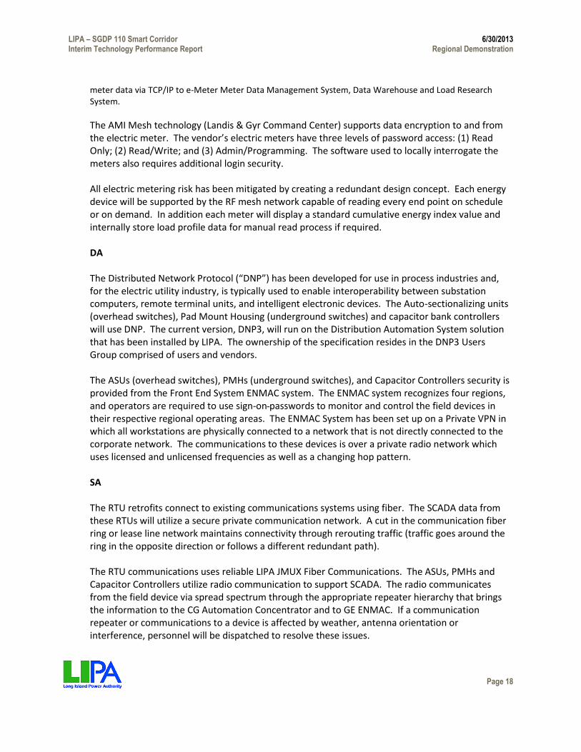
LIPA – SGDP 110 Smart Corridor 6/30/2013 Interim Technology Performance Report Regional Demonstration
Page 18
meter data via TCP/IP to e-Meter Meter Data Management System, Data Warehouse and Load Research System.
The AMI Mesh technology (Landis & Gyr Command Center) supports data encryption to and from the electric meter. The vendor’s electric meters have three levels of password access: (1) Read Only; (2) Read/Write; and (3) Admin/Programming. The software used to locally interrogate the meters also requires additional login security. All electric metering risk has been mitigated by creating a redundant design concept. Each energy device will be supported by the RF mesh network capable of reading every end point on schedule or on demand. In addition each meter will display a standard cumulative energy index value and internally store load profile data for manual read process if required. DA The Distributed Network Protocol (“DNP”) has been developed for use in process industries and, for the electric utility industry, is typically used to enable interoperability between substation computers, remote terminal units, and intelligent electronic devices. The Auto-sectionalizing units (overhead switches), Pad Mount Housing (underground switches) and capacitor bank controllers will use DNP. The current version, DNP3, will run on the Distribution Automation System solution that has been installed by LIPA. The ownership of the specification resides in the DNP3 Users Group comprised of users and vendors. The ASUs (overhead switches), PMHs (underground switches), and Capacitor Controllers security is provided from the Front End System ENMAC system. The ENMAC system recognizes four regions, and operators are required to use sign-on passwords to monitor and control the field devices in their respective regional operating areas. The ENMAC System has been set up on a Private VPN in which all workstations are physically connected to a network that is not directly connected to the corporate network. The communications to these devices is over a private radio network which uses licensed and unlicensed frequencies as well as a changing hop pattern. SA The RTU retrofits connect to existing communications systems using fiber. The SCADA data from these RTUs will utilize a secure private communication network. A cut in the communication fiber ring or lease line network maintains connectivity through rerouting traffic (traffic goes around the ring in the opposite direction or follows a different redundant path). The RTU communications uses reliable LIPA JMUX Fiber Communications. The ASUs, PMHs and Capacitor Controllers utilize radio communication to support SCADA. The radio communicates from the field device via spread spectrum through the appropriate repeater hierarchy that brings the information to the CG Automation Concentrator and to GE ENMAC. If a communication repeater or communications to a device is affected by weather, antenna orientation or interference, personnel will be dispatched to resolve these issues.

LIPA – SGDP 110 Smart Corridor 6/30/2013 Interim Technology Performance Report Regional Demonstration
Page 19
INTEROPERABILITY CONSIDERATIONS Interoperability is being accomplished in several ways. Data communication across the automation devices can be broken down into three distinct types of communications to the smart devices that will be used for this project, including a (1) Sonet JMUX network over fiber for non-TCP/IP applications; (2) DNP Protocol over unlicensed Spread Spectrum; and (3) secure encrypted wireless transmission. The retrofitted substation RTUs will use non-TCP/IP applications to carry data via Verizon leased-lines or Sonet / JMUX Fiber to the Energy Management System (EMS) Network or the Corporate Network. The Sonet JMUX network will use different channels of bandwidth that can be separated from each other. These channels are used in a point-to-point scheme. Because they do not rely on TCP/IP, their native communications protocols can be maintained from one end point to another. The ASUs, PMHs and capacitor controllers will be monitored and controlled using DNP Protocol over unlicensed Spread Spectrum radio communication utilizing frequency hopping. A CG Automation Concentrator distributes the data via Ethernet TCP/IP communications to and from the GE ENMAC distribution operation Control System. LIPA has already made investment to set up an Enterprise Data Management (EDM) policy, processes and program that is being used as a basis for all LIPA systems development and integration efforts going forward. The methodology includes a requirement that as part of any new systems development and implementation project certain work steps would be followed including the initial effort of assessing where data elements exist in LIPA’s semantic language framework in relationship to industry model standards (currently modeled to CIM, IEC 61850). All systems integration projects will be required to go through the modeling, development and implementation processes using LIPA standards that have been based on, and will continue to be shared will industry standards groups. DATA MANAGEMENT CONSIDERATIONS The meter data management system has standards-based, open architecture. The system architecture includes smart, flexible adapters to enterprise software applications and AMI and meter data collection systems. The databases store relationship, interval, event and other data for use by meter data management applications to manage the AMI systems and processes and for use by other applications throughout the enterprise. It provides two-way communication for meter data collection and other communications, such as load control or sending data to in-home displays. Communication processes include retrieving meter reads, sending configuration data to meters, issuing control commands to appliances or equipment linked to a variety of networks, sending price signals and other information over a network to in-home or in-premise devices. The communication systems supporting the smart grid devices will transfer data to the operating centers. Legacy systems such as GE ENMAC, GE HARRIS EMS, and OSI PI Historian data warehouse will interface with the Smart Grid devices or associated servers. The PI Historian system has an open architecture design to enable connectivity to enterprise systems supporting common modeling

LIPA – SGDP 110 Smart Corridor 6/30/2013 Interim Technology Performance Report Regional Demonstration
Page 20
techniques to better support the user population managing assets and system operation. This system not only requires security access but also resides on a separate network. The connection to the smart grid devices provides monitoring of system health for the distribution electric meters through use of unsolicited messages and response of control commands. Automated polling algorithms used to monitor the smart grid infrastructure devices can determine hardware failures and alert the operator alternative system solutions. The monitoring also provides an efficient and effective way to manage the maintenance / replacement of system assets for positive system reliability results.
CYBER SECURITY CONSIDERATIONS The deployment of the AMI can be broken up into two major areas such as security in the meter and security in the collector.
1) Security in the Meter Devices can be accessed locally via the optical port or remotely via the 900 MHz radio system. Access to the devices via the optical port requires an optical port password. A valid password is necessary to read data from or write data to the meter. The optical port password is set per the customer’s factory configuration and can only be changed by the utility using the meter vendor configuration software. Recommended policy for the utility is that passwords for meter access be disclosed on an as-needed basis.
2) Security in the Collectors The collector can be accessed locally via the optical port or remotely via the WAN. Access to the collector via the optical port requires an optical port password. A valid password is necessary to read data from or write data to the collector. The optical port password is set per the customer’s factory configuration and can only be changed by the utility using meter vendor’s configuration software. Recommended policy for the utility is that passwords for collector access be disclosed on an as-needed basis.
The substation RTUs use the existing General Electric SONET JMUX System is the transport mechanism between sites. The security layer rides over this transport mechanism. The JMUX uses individual dedicated channels of the SONET to isolate one path from another. For non-TCP/IP applications, such as bringing back RTU data these paths are not shared. The distribution automation devices use the LIPA 900MHz Spread Spectrum Communications Network to encapsulate DNP messages from the end-device (ASUs, PMHs and Capacitor Controllers) to the CG Concentrator and then passes the data to a private VPN Network that feeds information to/from the GE ENMAC. LIPA’s Information Security Policy is intended to ensure that the business benefits of sharing information and ideas are maximized while the information assets are protected from security risks. To control access to information assets according to business need, business risks and any legal or contractual requirements, LIPA will follow the NERC Critical Infrastructure Protection reliability standards CIP-002
LIPA – SGDP 110 Smart Corridor 6/30/2013 Interim Technology Performance Report Regional Demonstration
Page 21
and CIP-003 to identify those assets to which the NERC CIP standards apply. These standards require that LIPA will use a methodology that includes risk assessment to identify critical assets (002) and the critical cyber assets (003) that support those critical assets. All CCA data will reside within a secure physical and electronic perimeter as required in NERC CIP-005 and CIP-006. Employee awareness of security policies and the access to any CCA data will follow the requirements of NERC CIP-004. Management of the configuration of the firewalls and routers will be administered in compliance with NERC CIP-007. The following restrictions are in place at LIPA:
Access to LIPA’s information assets and services shall be controlled by the security requirements.
Information access rights to information assets and services shall be authorized, consistent with a user's job requirements and shall be modified when their job requirements change.
LIPA shall establish and maintain access controls that meet or exceed legal and regulatory requirements for the standards of due care.
Formal procedures shall be in place to control and review the allocation of access rights to information assets and services.
Access to information systems shall be controlled, and each user will maintain an individual user id and password.
Business owners are responsible for ensuring contractual controls are implemented by third party service providers when LIPA information assets are accessed, stored or processed at a third party site.
Users shall be made aware of their responsibilities for maintaining effective access controls, particularly regarding the use of identification and authentication mechanisms and the protection of both hard-copy and soft-copy information.
A clear desk and clear screen policy shall be implemented to reduce the risk of unauthorized access or damage to papers, media and information processing facilities.
The Smart Energy Corridor Project will include firewalls, routers, switches, access points, repeaters, radios, In-Home Displays/Gateways, internal network servers and clients on private networks will allow for the data to be transferred to the front-end systems as well as the internet. The use of DNP Protocol, Non-TCP/IP Applications and Data Encryption will support the smart grid cyber security standards. Stony Brook will test smart grid devices to determine their vulnerability to physical and cyber attacks. The results of these tests will be used to address cyber security concerns and will be reported to DOE and manufacturers, together with recommended solutions. The testing is described earlier in this narrative.
LIPA – SGDP 110 Smart Corridor 6/30/2013 Interim Technology Performance Report Regional Demonstration
Page 22
PROPOSED TEST PLAN There are 3 major areas that we are installing equipment to which supports the building of the Smart Grid in the 110 Corridor. The equipment for each of these areas will be procured, configured and tested prior to actual implementation. Below is a outline of the testing in each of the areas. ADVANCED METER INFRASTRUCTURE (AMI) There are 2 Hosted Systems (Test and Production) that Landis & Gyr has provided. The Test System is consists of the Hosted Server and Collector for communications to the meters within the company facility. The various AMI meter types (Landis & Gyr Focus RXR – residential and Landis & Gyr S4e RXR - commercial) that will be programmed and tested to communicate with the Test System. The testing will include communications (mesh network) to testing to the meter via routers and collectors, data flow to the MDMS (Meter Data Management System, connectivity to HANs (In Home Displays). This is in addition to the normal meter calibration/accuracy testing, meter firmware updates, programming of different rates and quantities measured in the meter and various alarming features. Meter Engineering and Shop personnel perform this on the Test System prior to implementation into the production environment. DISTRIBUTION AUTOMATION (DA) There are three distinct Distribution Automation devices that are being installed for the 110 Corridor that are ASUs, PMHs and Capacitor Bank Controllers. The ASUs and PMHs are devices that already exist on our distribution system. There are approximately 1000 of these devices on the system and the equipment is directly installed and tested when it is put into production. However, the configuration of how these devices communicate and integrate to the Distribution Automation System is performed in the DA Lab. There are three primary components of the Distribution Automation System that have to be configured which is the Radio Communication, CG Concentrator and GE ENMAC. There is a redundant test system which all configurations are tested for new devices prior to being deployed in the production environment. The Capacitor Bank Controller was a new device type that did not exist on the Distribution Automation System. The following had to be completed development of the DNP points to be retrieved from the device, configuration of the control parameters, type of communications, integration to ENMAC (device screen development and tele-control parameters), and CG Concentrator Configuration. Whenever a new device (CBC8000 Capacitor Bank Controller) is integrated we physically procure a sample device or its control unit which is then mounted and installed within our DA LAB. This allows for testing of the installation, configuration and control to be completed within the control system prior to implementation to the production environment. SUBSTATION AUTOMATION (SA) Substation Automation has installed Substation RTUs and Digital Meters that are tested when they are commissioned in the field. The commissioning includes communications to the Energy Management

LIPA – SGDP 110 Smart Corridor 6/30/2013 Interim Technology Performance Report Regional Demonstration
Page 23
System (EMS), testing of the inflow quantities being measured (such as Voltage, Current, kVar, kWh etc.) and connectivity of data flow to the PI Historian. In the event there are problems with the new equipment the old equipment is put back in place reducing the amount of any downtime.
DATA COLLECTION AND BENEFITS ANALYSIS
As stated previously the data gathered will be imported into the CYME Load Flow Analysis Tool to specifically perform the following: Feeder Loss Estimation Respond to DOE metric reporting requirement for yearly distribution feeder losses. Initially use spreadsheet analysis; later use CYME load flow analysis. Determine: 1) average feeder losses as percent of load; 2) total feeder cumulative MWH losses. This will use both Commercial and Residential AMI Data. Capacitor Control Optimization Use CYME load flow analyses to assess alternative capacitor control methods and settings, using present time-clock method and setting as a baseline. Uses AMI data availability as well as historical time clock and pager log database, to enable setting of capacitor banks on or off depending on day and hour simulated. Use CYME load flow analyses also to determine the automatic voltage settings to open and close the capacitor bank which will use data captured from the sensors at the capacitor bank location. TLM Enhancement Use AMI residential customer meter data to study customer load diversity (as a function of customer count, KW, KVAR, etc.) at the distribution transformer level. This will allow better sizing of the transformer. Customer Voltage Assessment Use AMI residential customer meter data to assess feeder voltage regulation. Develop report showing min/avg/max volts by transformer/customer/meter report. Enhance report later to include commercial customer AMI data, when available. Feeder Optimization (Phase Balance, Voltage Regulation) Build advanced CYME Corridor network model using the database incorporating feeder breaker, ASU, and capacitor bank metering points. Build CYME EPM (Energy Profile Manager) database to enable CYME Load Flow with Profiles (LFP) analyses. This will include information from SCADA and PI. 1) Feeder breaker amps and power factor for the annual peak day (7/18/13); 2) ASU amps and power factor for the annual peak day; 3) Capacitor bank amps and power factor for annual. Perform enhanced CYME Load Allocation. Assess feeder optimization using 24 hour and seasonal LFP analyses.

LIPA – SGDP 110 Smart Corridor 6/30/2013 Interim Technology Performance Report Regional Demonstration
Page 24
RESULTS
OPERATION OF SMART GRID TECHNOLOGIES AND SYSTEMS
Due to the devastation and subsequent restoration efforts resulting from Hurricane Sandy in late 2012, the
Operations and Demonstration phase of the project have not yet begun. Therefore, no results are being reported at
this time.
ENERGY STORAGE SYSTEM PERFORMANCE PARAMETERS
Due to the devastation and subsequent restoration efforts resulting from Hurricane Sandy in late 2012, the
Operations and Demonstration phase of the project have not yet begun. Therefore, no results are being reported at
this time.
IMPACT METRICS AND BENEFITS ANALYSIS
Due to the devastation and subsequent restoration efforts resulting from Hurricane Sandy in late 2012, the
Operations and Demonstration phase of the project have not yet begun. Therefore, no results are being reported at
this time.
STAKEHOLDER FEEDBACK
Due to the devastation and subsequent restoration efforts resulting from Hurricane Sandy in late 2012, the
Operations and Demonstration phase of the project have not yet begun. Therefore, no results are being reported at
this time.
LIPA – SGDP 110 Smart Corridor 6/30/2013 Interim Technology Performance Report Regional Demonstration
Page 25
CONCLUSIONS
PROJECTIONS OF DEMONSTRATION AND COMMERCIAL-SCALE SYSTEM PERFORMANCE
Due to the devastation and subsequent restoration efforts resulting from Hurricane Sandy in late 2012, the
Operations and Demonstration phase of the project have not yet begun. Therefore, no conclusions are being reported
at this time.
LESSONS LEARNED AND BEST PRACTICES
Due to the devastation and subsequent restoration efforts resulting from Hurricane Sandy in late 2012, the
Operations and Demonstration phase of the project have not yet begun. Therefore, no conclusions are being reported
at this time.

LIPA – SGDP 110 Smart Corridor 6/30/2013 Interim Technology Performance Report Regional Demonstration
Page 26
CONTACTS
DOE Project Manager: Thomas George U. S. DOE/NETL Morgantown Campus 3610 Collins Ferry Road PO Box 880 Morgantown, WV 26507-0880 [email protected] 304.285.4825
Principal Investigator: Ming Mui Long Island Power Authority 333 Earle Ovington Boulevard, Suite 403 Uniondale, New York 11553-3645 [email protected] 516.719.9229 National Grid: Sunil KAtwala 175 E. Old Country Road Hicksville, NY 11801 [email protected] 516.545.5366 Farmingdale State College: Dr. Kamal Shahrabi Dean, School of Engineering Technology Farmingdale State College (SUNY) 2650 Broadhollw Road, Lupton 104 Farmingdale, NY 11735
[email protected] 631.420.2256
Stony Brook University: Dr. Eugene Feinberg Department of Applied Mathematics and Statistics Stony Brook University Stony Brook, NY 11794-3600
[email protected] 631.632.7189

LIPA – SGDP 110 Smart Corridor 6/30/2013 Interim Technology Performance Report Regional Demonstration
Page 27
APPENDICES
Due to the devastation and subsequent restoration efforts resulting from Hurricane Sandy in late 2012, the
Operations and Demonstration phase of the project have not yet begun. Therefore, no appendices are being included
at this time.


