Intergranular Attack in Welded Stress-Corrosion Resistant...
15
Intergranular Attack in Welded Stress-Corrosion Resistant Stainless Steels Satisfactory stress corrosion resistance is obtained using arc welding and, depending on the base metal, Type 376/. or 309L stainless steel filler metals BY J. HONEYCOMBE AND T. C. GOOCH Introduction Although austenitic stainless steels have excellent corrosion resistance in a wide variety of media, they exhibit a high susceptibility to stress corrosion cracking (SCC) in hot aqueous envi- ronments containing chloride or hy- droxyl ions. Industrial interest has, therefore, been increasing in ferritic and duplex-structured stainless steels (containing 17-27% chromium with 0-5%Ni) which are resistant to stress corrosion cracking. Despite their resistance to SCC, the conventional ferritic stainless steels containing about 17%Cr possess several disadvan- tages; in particular, their welded joints may show excessive grain growth and embrittlement, and sensitivity to inter- granular corrosion.' Alloys have been recently devel- oped in an attempt to overcome these problems. In view of the wide range of potential applications of such alloys, an investigation was initiated at The Welding Institute to study their weld- ing behavior so that practical recom- mendations regarding optimum pro- cedures can be formulated. The pres- ent paper considers the effects of welding in causing susceptibility to intercrystalline attack of representa- tive materials. Materials The alloys studied were intended to cover the different microstructural Paper presented at the 58th AWS Annual Meeting held in Philadelphia, Pennsylvania, during April 25-29, 1977. j. HONEYCOMBE is Senior Research Met- allurgist and T. C. COOCH is Principal Research Metallurgist, The Welding Insti- tute, Abington, Cambridge, England. approaches to avoiding chloride- induced SCC. The materials were a conventional ferritic grade (AISI 430) to afford a base-line for comparison, a ferrite-martensite alloy, two ferrite- austenite steels, and a fully ferritic steel having extra low interstitial (ELI) element content.* The particular ma- terials employed and the available thicknesses are given in Table 1. Test Weld Preparation The processes employed were shielded metal arc (SMA), gas tungsten arc (GTA), gas metal arc (GMA), submerged arc (SA) and electron beam (EB). Apart from the autogenous GTA and EB welds, three types of commer- cially available filler metals were selected for study—a matching or near- matching alloy; an austenitic stainless steel (either 18/10/3Mo or 23/12/Mo, subsequently referred to as Types 316L or 309L-Mo respectively) as might be employed in practice;- and a nickel alloy, as in principle representing a weld metal of high resistance to chlo- ride-induced stress corrosion. The nominal compositions of the filler metals used are shown in Tables 2 and 3, with available deposit analyses. Butt welds were made in a restrain- ing jig as indicated in Tables 4 and 5, with interpass temperature being held at 150 C (302 F) maximum. No weld was given a postweld heat treatment. Transverse sections of all welds were *Material was tested as 2.5 mm (0.1 in.) thick sheet and 13 mm (0.5 in.) plate. It is understood from the material manufacturer that subsequent to carrying out the present tests on the thinner material, the composi- tion has been modified, although no details are available. The thicker material was supplied and tested after the reported composition change. examined metallographically. SMA Welds All the manual metal arc welds employed a 75 deg included angle, single V-groove preparation with a 1.5 mm (0.060 in.) root face and no root gap, and were made with an autoge- nous GTA root and argon back purging for better control of penetration. The welds in the ferritic-austenitic alloys were deposited using nomi- nally high and low energy inputs. t With the single phase 26%Cr-1%Mo, because of its tendency to grain growth, low energy inputs only were used. GTA Welds Joint preparation and root run were as used with the SMA welds. For the 26%Cr-1%Mo steel, the argon gas flow through the torch was kept high at approximately 25-30 l/min with back purging maintained at 6 l/min; 1 for the other steels, the torch flow rate was 10 l/min. GMA Welds The preparation used was a 70 deg single V-groove with a 3 mm (0.12 in.) root face and no root gap. Following welding from one side, the weld was back gouged and a sealing run inserted on the reverse side. The shielding gas for the two duplex alloys was argon-2%0 L . or argon depending on the filler, while for the 26%Cr-1%Mo it was either pure argon or argon-1%0,. The gas flow was kept high with argon back purging in all jEncrgy input defined as: (Volts X Amps X 60/speed (mm/min) X 1000) x kj/mm WELDING RESEARCH SUPPLEMENT I 339-s
Transcript of Intergranular Attack in Welded Stress-Corrosion Resistant...
Intergranular Attack in Welded Stress-Corrosion Resistant Stainless Steels
Satisfactory stress corrosion resistance is obtained using arc welding and, depending on the base metal,
Type 376/. or 309L stainless steel filler metals
BY J. HONEYCOMBE AND T. C. GOOCH
Introduction
Although austenitic stainless steels have excellent corrosion resistance in a wide variety of media, they exhibit a high susceptibility to stress corrosion cracking (SCC) in hot aqueous environments containing chloride or hy-droxyl ions. Industrial interest has, therefore, been increasing in ferritic and duplex-structured stainless steels (containing 17-27% chromium with 0-5%Ni) which are resistant to stress corrosion cracking. Despite their resistance to SCC, the conventional ferritic stainless steels containing about 17%Cr possess several disadvantages; in particular, their welded joints may show excessive grain growth and embritt lement, and sensitivity to intergranular corrosion.'
Alloys have been recently developed in an attempt to overcome these problems. In view of the wide range of potential applications of such alloys, an investigation was initiated at The Welding Institute to study their welding behavior so that practical recommendations regarding opt imum procedures can be formulated. The present paper considers the effects of welding in causing susceptibility to intercrystalline attack of representative materials.
Materials
The alloys studied were intended to cover the different microstructural
Paper presented at the 58th AWS Annual Meeting held in Philadelphia, Pennsylvania, during April 25-29, 1977.
j. HONEYCOMBE is Senior Research Metallurgist and T. C. COOCH is Principal Research Metallurgist, The Welding Institute, Abington, Cambridge, England.
approaches to avoiding chloride-induced SCC. The materials were a conventional ferritic grade (AISI 430) to afford a base-line for comparison, a ferrite-martensite alloy, two ferrite-austenite steels, and a fully ferritic steel having extra low interstitial (ELI) element content.* The particular materials employed and the available thicknesses are given in Table 1.
Test Weld Preparation
The processes employed were shielded metal arc (SMA), gas tungsten arc (GTA), gas metal arc (GMA), submerged arc (SA) and electron beam (EB). Apart from the autogenous GTA and EB welds, three types of commercially available filler metals were selected for study—a matching or near-matching alloy; an austenitic stainless steel (either 18/10/3Mo or 23/12/Mo, subsequently referred to as Types 316L or 309L-Mo respectively) as might be employed in practice;- and a nickel alloy, as in principle representing a weld metal of high resistance to chloride-induced stress corrosion. The nominal compositions of the filler metals used are shown in Tables 2 and 3, w i th available deposit analyses.
Butt welds were made in a restraining jig as indicated in Tables 4 and 5, wi th interpass temperature being held at 150 C (302 F) maximum. No weld was given a postweld heat treatment. Transverse sections of all welds were
*Material was tested as 2.5 mm (0.1 in.) thick sheet and 13 mm (0.5 in.) plate. It is understood from the material manufacturer that subsequent to carrying out the present tests on the thinner material, the composition has been modified, although no details are available. The thicker material was supplied and tested after the reported composition change.
examined metallographically.
SMA Welds
All the manual metal arc welds employed a 75 deg included angle, single V-groove preparation with a 1.5 mm (0.060 in.) root face and no root gap, and were made wi th an autogenous GTA root and argon back purging for better control of penetration.
The welds in the ferritic-austenitic alloys were deposited using nominally high and low energy inputs.t With the single phase 26%Cr-1%Mo, because of its tendency to grain growth, low energy inputs only were used.
GTA Welds
Joint preparation and root run were as used with the SMA welds. For the 26%Cr-1%Mo steel, the argon gas f low through the torch was kept high at approximately 25-30 l /min wi th back purging maintained at 6 l /min; 1 for the other steels, the torch f low rate was 10 l /min.
GMA Welds
The preparation used was a 70 deg single V-groove with a 3 mm (0.12 in.) root face and no root gap. Following welding from one side, the weld was back gouged and a sealing run inserted on the reverse side.
The shielding gas for the two duplex alloys was argon-2%0L. or argon depending on the filler, whi le for the 26%Cr-1%Mo it was either pure argon or argon-1%0,. The gas f low was kept high with argon back purging in all
jEncrgy input defined as: (Volts X Amps X 60/speed (mm/min) X 1000) x kj/mm
W E L D I N G RESEARCH SUPPLEMENT I 339-s
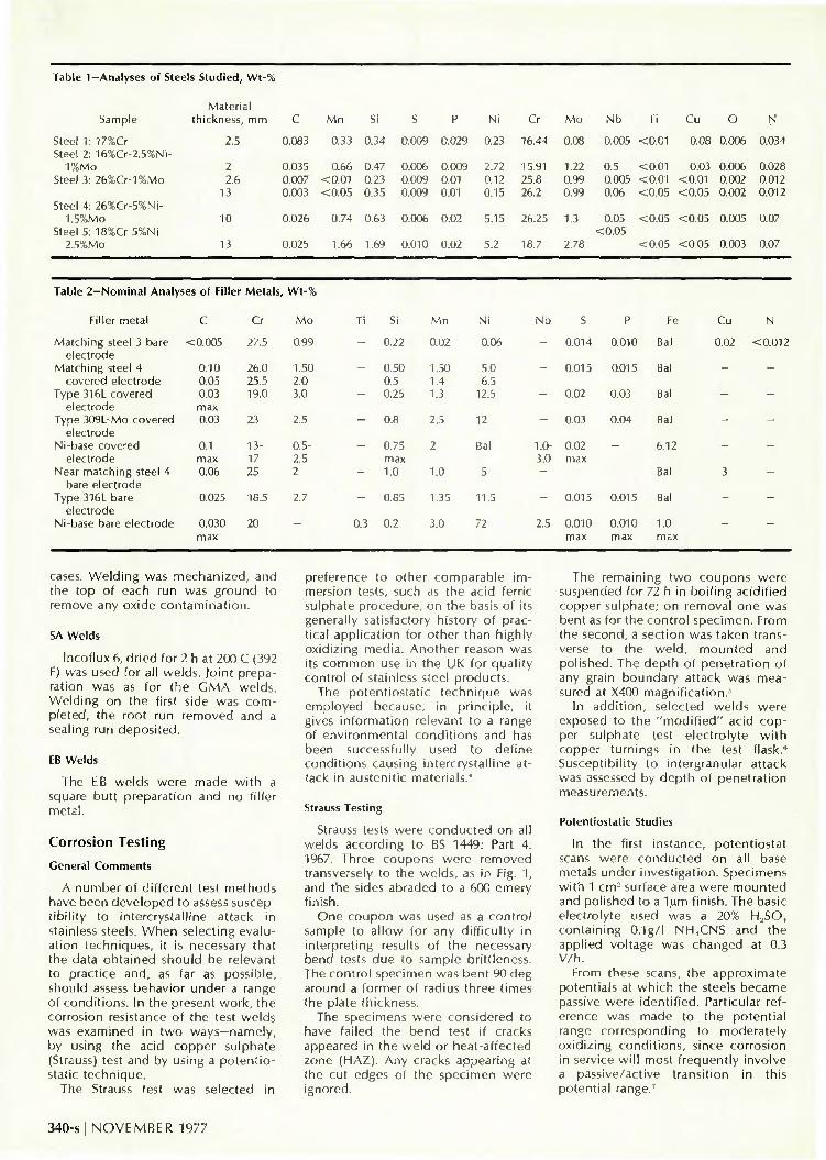
Table 1-Analyses of Steels Studied, Wt-%
Sample
Steel 1: 17%Cr Steel 2: 16%Cr-2.5%Ni-
1%Mo Steel 3: 26%Cr-1%Mo
Steel 4: 26%Cr-5%Ni-1.5%Mo
Steel 5: 18%Cr-5%Ni-2.5%Mo
Material thickness, mm
2.5
2 2.6
13
10
13
C
0.083
0.035 0.007 0.003
0.026
0.025
Mn Si S P Ni Cr Mo
0.33 0.34 0.009 0.029 0.23 16.44 0.08
Nb Ti Cu O N
0.005 <0.01 0.08 0.006 0.034
0.66 0.47 0.006 0.009 2.72 15.91 1.22 0.5 <0.01 0.03 0.006 0.028 0.007 <0.01 0.23 0.009 0.01 0.003 <0.05 0.35 0.009 0.01
0.74 0.63 0.006 0.02
1.66 1.69 0.010 0.02
0.12 25.8 0.15 26.2
0.99 0.005 <0.01 <0.01 0.002 0.012 0.99 0.06 <0.05 <0.05 0.002 0.012
5.15 26.25 1.3
5.2 18.7
0.05 <0.05 <0.05 0.005 0.07 <0.05
2.78 <0.05 <0.05 0.003 0.07
Table 2-Nominal Analyses of Filler Metals, Wt-%
Filler metal C Cr Mo
Matching steel 3 bare <0.005 27.5 0.99 electrode
Matching steel 4 0.10 26.0 1.50 covered electrode 0.05 25.5 2.0
Type 316L covered 0.03 19.0 3.0 electrode max
Type 309L-Mo covered 0.03 23 2.5 electrode
Ni-base covered 0.1 13- 0.5-electrode max 17 2.5
Near matching steel 4 0.06 25 2 bare electrode
Type 316L bare 0.025 18.5 2.7 electrode
Ni-base bare electrode 0.030 20 max
Ti
-
—
-
-
-
-
-
0.3
Si
0.22
0.50 0.5 0.25
0.8
0.75 max 1.0
0.85
0.2
Mn
0.02
1.50 1.4 1.3
2.5
2
1.0
1.35
3.0
Ni
0.06
5.0 6.5
12.5
12
Bal
5
11.5
72
Nb S P Fe
- 0.014 0.010 Bal
-
-
-
1.0-3.0
-
-
2.5
0.015
0.02
0.03
0.02 max
-
0.015
0.010 max
0.015
0.03
0.04
—
-
0.015
0.010 max
Bal
Bal
Bal
6.12
Bal
Bal
1.0 max
Cu N
0.02 <0.012
cases. W e l d i n g was m e c h a n i z e d , a n d t h e t o p o f each run was g r o u n d t o r emove any o x i d e c o n t a m i n a t i o n .
SA Welds
Incoflux 6, dried for 2 h at 200 C (392 F) was used for all welds. Joint preparation was as for the GMA welds. Welding on the first side was completed, the root run removed and a sealing run deposited.
EB Welds
The EB welds were made wi th a square butt preparation and no filler metal.
Corrosion Testing
General Comments
A number of different test methods have been developed to assess susceptibil ity to intercrystalline attack in stainless steels. When selecting evaluation techniques, it is necessary that the data obtained should be relevant to practice and, as far as possible, should assess behavior under a range of conditions. In the present work, the corrosion resistance of the test welds was examined in two ways—namely, by using the acid copper sulphate (Strauss) test and by using a potent io-static technique.
The Strauss test was selected in
preference to other comparable immersion tests, such as the acid ferric sulphate procedure, on the basis of its generally satisfactory history of practical application for other than highly oxidizing media. Another reason was its common use in the UK for quality control of stainless steel products.
The potentiostatic technique was employed because, in principle, it gives information relevant to a range of environmental condit ions and has been successfully used to define conditions causing intercrystalline attack in austenitic materials.'
Strauss Testing
Strauss tests were conducted on all welds according to BS 1449: Part 4: 1967. Three coupons were removed transversely to the welds, as in Fig. 1, and the sides abraded to a 600 emery finish.
One coupon was used as a control sample to allow for any difficulty in interpreting results of the necessary bend tests due to sample brittleness. The control specimen was bent 90 deg around a former of radius three times the plate thickness.
The specimens were considered to have failed the bend test if cracks appeared in the weld or heat-affected zone (HAZ). Any cracks appearing at the cut edges of the specimen were ignored.
The remaining two coupons were suspended for 72 h in boi l ing acidified copper sulphate; on removal one was bent as for the control specimen. From the second, a section was taken transverse to the weld, mounted and polished. The depth of penetration of any grain boundary attack was measured at X400 magnification."'
In addit ion, selected welds were exposed to the "mod i f i ed " acid copper sulphate test electrolyte w i th copper turnings in the test flask." Susceptibility to intergranular attack was assessed by depth of penetration measurements.
Potentiostatic Studies
In the first instance, potentiostat scans were conducted on all base metals under investigation. Specimens with 1 cm2 surface area were mounted and polished to a 1,um finish. The basic electrolyte used was a 20% H,SO, containing O.lg/I NH..CNS and the applied voltage was changed at 0.3 V /h .
From these scans, the approximate potentials at which the steels became passive were identif ied. Particular reference was made to the potential range corresponding to moderately oxidizing conditions, since corrosion in service wi l l most frequently involve a passive/active transition in this potential range.7
340-s I NOVEMBER 1977

Table 3—Deposit Analys
Consumable
Matching steel 3 bare electrode
Matching steel 4 covered electrode
Type 316L covered electrode
Type 309L-Mo covered electrode
Nickel-base covered electrode
Near matching steel 4 bare electrode
Type 316L bare electrode
Nickel-base bare electrode
:es, Wt-%'
Base metal
Steel 3 Steel 3 Steel 3
Steel 4
Steel 4
Steel 3 Steel 5
Steel 3 Steel 4 Steel 5
Steel 4 Steel 4 Steel 4
Steel 4 Steel 5 Steel 4 Steel 5
Steel 3 Steel 4 Steel 4 Steel 5
•'
Process
GTA G M A " "
SA
SMA
SMA
SMA SMA
SMA SMA SMA
GTA GMA
SA
GMA GMA
SA SA
SA GTA
SA SA
C
0.006 < 0.026
0.04
0.08
0.05
0.02 0.02
0.04 0.04 0.04
0.05 0.05 0.06
0.02 0.02 0.04 0.04
0.03 0.03 0.04 0.04
Cr
28.2 27.1 26.1
26.9
21.0
24.4 22.9
13.8 16.3 15.6
26.5 24.7 26.2
19.7 18.8 20.5 18.2
22.0 20.9 22.1 21.3
M o
0.90 0.98 1.01
1.46
2.62
2.36 2.7
1.13 0.90 1.12
2.31 2.2 2.14
2.59 2.81 2.38 2.75
0.29 0.09 0.50 0.60
Ti
< 0 . 0 5 < 0 . 0 5 < 0 . 0 5
< 0.05
< 0.01
0.01 0.05
< 0.05 < 0 . 0 5 < 0 . 0 5
< 0.01 < 0 . 0 1 < 0.05
< 0.01 < 0.01
0.01 0.02
0.14 0.36 0.09 0.17
Al
N D ND
< 0.05
< 0.05
< 0.05
0.05 0.05
< 0.05 < 0.05 < 0.05
< 0.05 < 0.05 < 0.05
< 0.05 < 0.05 < 0.05 < 0.05
0.08 < 0.05
0.10 0.07
Si
0.20 0.22 0.31
0.98
0.22
0.63 0.89
0.27 0.25 0.39
0.39 0.38 0.48
0.77 0.83 0.78 1.01
0.56 0.41 0.67 0.84
Mn
< 0.05 < 0.05
0.05
0.76
1.28
1.36 1.68
2.23 1.57 1.96
0.86 0.83 0.81
1.26 1.40 1.38 1.59
2.43 2.94 2.28 2.92
Ni
0.07 0.14 0.13
5.14
1 1.0
10.0 11.1
70.4 63.1 63.2
5.1 4.7 5.35
10.8 11.0 10.7 11.0
55.0 66.9
Bal 59.2
Nb
0.06 0.07
< 0 . 0 5
< 0.05
< 0.01
< 0.05 < 0.05
2.28 1.82 2.09
< 0.01 < 0.01 < 0.01
< 0.01 < 0 . 0 1 < 0.01 < 0.01
1.80 2.36 1.72 1.95
S
0.009 0.006 0.007
0.012
0.015
0.013 0.013
ND ND ND
0.016 0.017 0.015
0.012 0.012 o.ori 0.012
ND ND
0.012 ND
P
0.011 0.016 0.016
0.030
0.016
0.026 0.020
ND ND ND
0.026 0.025 0.026
0.014 0.014 0.016 0.017
ND ND
0.020 ND
Fe
Bal Bal Bal
Bal
Bal
Bal Bal
9.6 15.4 15.4
Bal Bal Bal
Bal Bal Bal Bal
17.6 5.9
26.1 14.7
Cu
0.05 < 0 . 0 5 < 0 . 0 5
< 0.05
0.03
0.05 0.06
0.13 0.09 0.11
1.4 1.32 1.04
0.02 0.03 0.03 0.05
0.05 0.06 0.1 0.07
' "ND = nol dele ""Ar shielding.
The critical potentials below which corrosion occurred were more precisely defined for the various weld areas by a controlled potential etching procedure.7 The polished specimens were exposed to the electrolyte at a potential slightly more positive than the passivation potential indicated by the scans, and examined at X500 magnification for any sign of corrosion. If none had taken place, the potential was lowered by 0.01 V intervals, the specimen being repolished before each change, until attack was first observed.
The nature of the attack was identified and the potential below which preferential intercrystalline weld metal or HAZ attack occurred was noted. Preliminary assessment was based on a 20 min exposure period; critical potentials were then more closely defined using 16 hr and 64 hr periods.
Additional studies were carried out in the basic electrolyte wi th 3% NaCI additions. This was for two reasons: First, trials in 20% H,SO, + 0.1 g/l NH4CNS indicated the passive fi lm formed on the experimental steels to be kinetically stable, and the effect of chloride ions in promoting passive film breakdown was examined. Second, intergranular attack in service has been associated with chloride media;s it
Table 4—Conditions for GTA Ri
Steel no.
1 2 3
'"25.4 mm = I inch
Volts, V
11 10 12
ins in Thin Sheet Samples
Currents, A
120 100 100
Travel speed,
m m / m i n
190 190 125
Input energy,
k j / m m " "
0.4 0.3 0.5
was, therefore, desirable to examine the role of chloride ions in inducing preferential grain boundary corrosion in the materials studied.
Results
Metallographic Observations
Steel 1: AISI 430 (17%Cr). The base metal was fully ferritic containing bands of chromium carbide particles. After autogenous GTA welding, both the weld metal and the HAZ exhibited duplex structures wi th martensite along the grain boundaries and on certain planes throughout the grains—Fig. 2.
The grain size of the weld metal was about ASTM 1. Close to the fusion boundary where transformation to austenite had occurred during welding, the HAZ exhibited a smaller grain
size closer to that of the base metal. In the low temperature HAZ, the structure reverted to single-phase ferrite wi th a grain size (ASTM 5) only slightly larger than the base metal (ASTM 6).
5tee/ 2: Ferrite-Martensite (16%Cr/ 2.7%Ni/1%Mo/0.5%Nb). The base metal showed a fine, banded ferrite-martensite structure, containing Nb(C,N) particles—Fig. 3. In the weld metal and high temperature HAZ of autogenous GTA welds, transformation occurred to a fully ferritic structure of ASTM 3-4 grain size, wi th Nb(C,N) precipitation at grain boundaries and throughout the grains. Niobium carbide eutectics were apparent in the HAZ.
Steel 3: Ferritic ELI (26%Cr/1%Mo). The base metal was fully ferritic—Fig. 4. In both thicknesses examined, the grain size was variable, giving a banded appearance; in the 13 mm (0.5
W E L D I N G RESEARCH SUPPLEMENT I 341-s

Table 5-
Weld no.
1
2 3 4
5
6 7
8
9 11 12
2
3 4 5 6 7
8
9 10
11 12 13
14 15
1 2 3 4 5 6 7
8 9
10 11 12 13
""One l/m ""25.4 mm
-Welding I
Process
SMA
SMA SMA GMA
GMA
GMA GTA
GTA
GTA SA EB
SMA
SMA SMA SMA SMA GMA
GMA
GMA SA
SA SA GTA
GTA EB
SMA SMA SMA SMA SMA SMA GMA
GMA SA SA GTA GTA EB
Parameters for Plate Samples
Filler metal and diameter,
mm
Type 309L-MO 3.25
Type 316L 3.25 Ni-base 3.25 Matching composi
t ion 1.6 Matching composi
t ion 1.6 Ni-base 1.2 Matching composi
t ion 2.3 Matching composi
tion 2.3 Ni-base 1.6 Ni-base 1.6
-
Matching composit ion 3.25
Type 316L 4 Type 316L 3.25 Ni-base 4 Ni-base 3.25 Near matching
composit ion Type 316L 1.2
Ni-base 1.2 Near matching
composition 1.6 Type 316L 1.2 Ni-base 1.6 Near matching
composit ion 1.6 Ni-base 1.6
-
Type 309L-MO 4 Type 309L-MO 3.25 Type 316L 4 Type 316L 3.25 Ni-base 4 Ni-base 3.25 Type 316L 1.2
Ni-base 1.2 Type 316L 1.2 Ni-base 1.6 Type 316L 1.2 Ni-base 1.6
-in = 2.1 cu fl/hr. = 1 inch.
"'Excluding autogenous GTA root runs.
Shielding gas" '
or flux
Steel 3,
---Argon 30 l /min
Argon + 1 % 0 , 30 l /min
Argon 25 l /min Argon 20 l /min
Argon 25 l /min
Argon 30 l /min Inco flux 6
-
Current, A
26%Cr/1%Mo 90
85 80
250
250
220 140
220
145 270
45 x 1 0 "
Steel 4, 26%Cr/5%Ni/1.5%Mo
-
----Argon + 2%02
25 l /min Argon + 2%Oz
25 l /min Argon 25 l /m in Inco Flux 6
Inco Flux 6 Inco Flux 6 Argon 10 l /min
Argon 10 l /m in
-
80
130 85
130 80
220
230
230 280
210 300 145
140 40 X 10- '
Steel 5, 18%Cr/5%Ni/2.7%Mo
------Argon + 2%0 2
27 l /min Argon 25 l /min Inco flux 6 Inco flux 6 Argon 10 l /m in Argon 10 l /min
-
160 85
145 80
130 75
230
230 210 310 140 140
36 X 10"*
Voltage, V
25
25 25 24
24
26 11
11
11 28
140 x 10:'
24
24 25 25 25 27
22
22 27
31 30 11
11 140 X 103
24 24 25 24 25 25 22
22 31 26 11 11
140 X 10;*
Speed, m m / m i n " "
200
180 165 360
360
430 100
125
95 400
1125
200
200 180 200 200 310
280
280 360
360 360 95
95 1250
200 180 250 180 200 130 280
280 360 400 95
100 1000
Input energy,
k j / m m " "
0.7
0.7 0.7 1.0
1.0
0.8 0.9
1.1
1.0 1.1 0.3
0.6
1.2 0.7 1.2 0.6 1.2
1.2
1.2 1.2
1.1 1.5 1.0
1.0 0.3
1.1 0.7 0.8 0.6 1.0 0.9 1.5
1.1 1.1 1.2 1.0 0.9 0.3
No. of passes"''
10
10 10 7
8
6 20
1.3
14 5 1
5
3 5 3 5 4
3
3 4
3 3
13
I I 1
5 8 6 7 6 8 5
5 3 3
12 14
1
in.) thick plate, grains of up to 0.5 mm (0.02 in.) width and 50 mm (1.97 in.) length were observed.
On welding, considerable HAZ grain growth occurred. Wi th the sheet material, the peak grain size in the HAZ was about ASTM 2, although that of the weld metal was considerably larger. In the heavier gauge plate, HAZ grain sizes of about ASTM 0 were developed. Some subgrain structure was noted adjacent to the fusion boundary, particularly wi th nonmatching composit ion consumables.
Matching composition weld metals showed pronounced epitaxial growth, regardless of process. Ferrite contents of welds made with austenitic stainless steel consumables were quite high. With nickel-base weld metal and all processes, some small hot cracks were found, especially initiating from the fusion boundary. Weld metal cracking was also observed in the matching composition filler SA weld, while HAZ cracking was noted in the GMA weld made using a high nickel consumable, the cracks propagating along large
grains into base metal outside the grain-coarsened region.
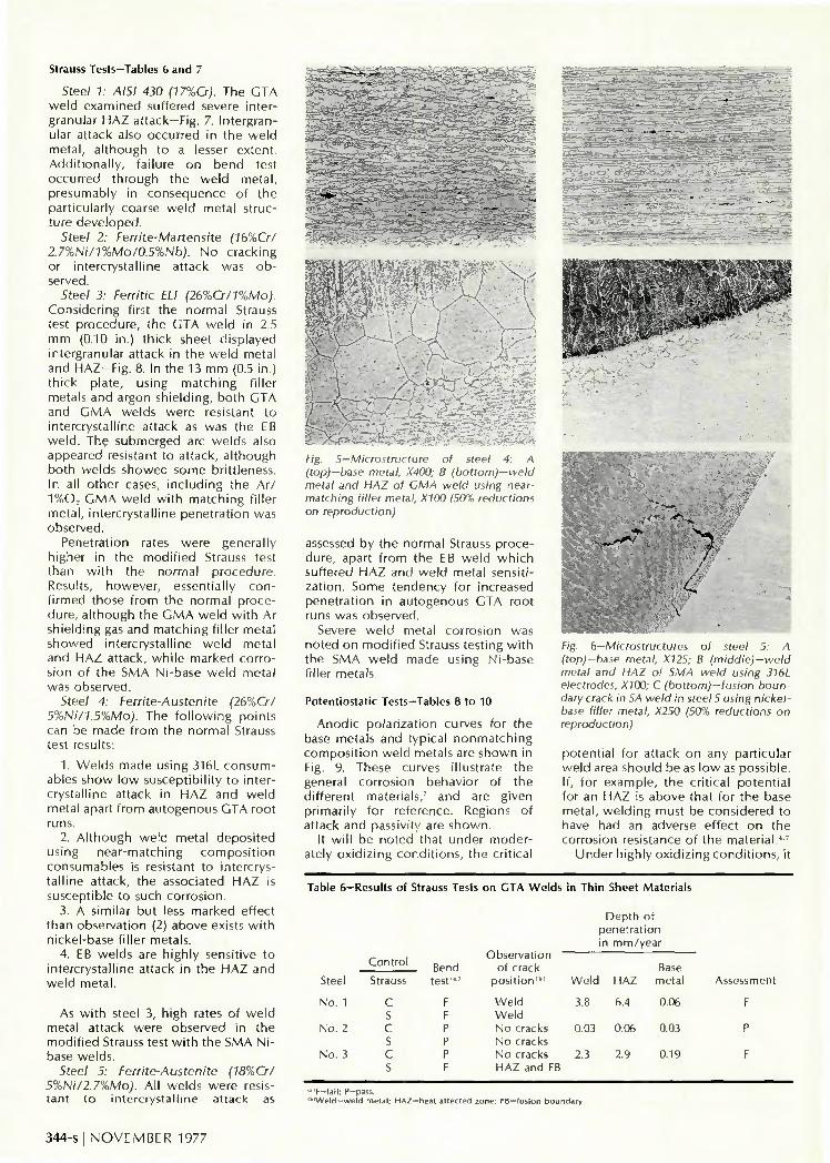
Steel 4: Ferrite-Austenite (26%Cr/ 5%Ni/1.5%Mo). This duplex alloy contained 20-30% austenite-Fig. 5. The matrix ferrite grain size was quite small (ca ASTM 6), wi th the primary austenite banded by rolling. Secondary austenite produced during final solution treatment had formed mainly at ferrite grain boundaries, although not always parallel to the rolling plane.
On heating during welding, transformation to ferrite occurred in the
342-s I NOVEMBER 1977

Fig. 7—Strauss test sample geometry, specimen bent as indicated
S t e ,;••'• '*••*. ->
, , . : . . . - . A . v £ £ ? . * - * * * * - • • S * - W . - - . .»».«.-, _ . , - . h— —»— -*_*--__ «5 »^&i ' : ' - - -,-.>.=u— „.
^ "V: :': v. •-•^.sSk
Fig. 2—Microstructures of steel 1: A (top)-base metal, X320; B (middle)-weld metal and high temperature HAZ, X200; C (bottom)-Low temperature HAZ, X200 (50% reductions on reproduction)
HAZ, wi th associated grain growth. On cooling, austenite reformed at grain boundaries and to a lesser extent within the grains. Carbide and nitride
Fig. 3—Microstructure of steel 2: A (top)-base metal, X630; B (bottom)-weld metal and high temperature HAZ, X600 (50% reductions on reproduction)
decoration of subgrain boundaries was evident, wi th a precipitate-depleted area around grain boundaries. As assessed visually, repeated thermal cycling in a multipass weld slightly increased the total austenite content, wi thout affecting the peak grain size.
The matching or near-matching composition weld metals showed a coarse, columnar structure wi th epitaxial growth from the HAZ. Some intergranular austenite was observed, the austenite being least in the autogenous GTA and EB weld metals. Welds made wi th Type 316L filler metals showed increased ferrite contents, wi th austenite and ferrite tending to form in a parallel lath-like structure. Using nickel-base filler metals, a
Fig. 4—Microstructure of steel 3: A (top)-base metal, 13 mm plate, X100; B (middle)—weld metal and HAZ of CTA weld in 13 mm plate with matching composition filler metal, X50; C (bottom)-HAZ cracking in CMA weld in steel 3, using nickel-base filler metal, X80 (50% reductions on reproduction)
sharply defined fusion boundary was apparent, wi th little correspondence between HAZ grain size and weld metal solidification structure.
Wi th all processes, nickel-base weld metals showed small hot cracks adjacent to the fusion boundary. In addit ion, some weld metal solidification cracking was observed in the matching composition SMA and SA welds.
Steel 5: Ferrite-Austenite (18%Cr/ 5%Ni/2.7%Mo). Microstructural observations were essentially the same as for steel 4 with respect to transformation behavior during welding and weld metal characteristics—Fig. 6. The base metal of steel 5 contained more austenite (ca 40%); compared wi th steel 4, the HAZ structures showed finer grain sizes and higher austenite contents, while the transformed HAZ's were narrower. Weld metal cracking was noted wi th nickel-base filler metals.
W E L D I N G RESEARCH SUPPLEME NT I 343-s
Strauss Tests—Tables 6 and 7
Steel 1: AISI 430 (17%Cr). The GTA w e l d e x a m i n e d suf fered severe in ter granu lar H A Z attack—Fig. 7. I n t e rg ran ular a t tack also occu r red in t h e w e l d me ta l , a l t h o u g h to a lesser ex ten t . A d d i t i o n a l l y , fa i lu re o n b e n d test o c c u r r e d t h r o u g h the w e l d m e t a l , p resumab ly in c o n s e q u e n c e o f t h e par t i cu la r l y coarse w e l d meta l s t ruct u r e d e v e l o p e d .
Steel 2: Ferrite-Martensite (IbXCrl 2.7%Ni/l%Mo/0.5%Nb). N o c rack ing or in te rc rys ta l l i ne at tack was o b served.
Steel 3: Ferritic ELI (26%Cr/l%Mo). Cons ide r i ng first the n o r m a l Strauss test p r o c e d u r e , t he G T A w e l d in 2.5 m m (0.10 in.) th i ck sheet d i sp layed in te rgranu la r a t tack in t he w e l d meta l and H A Z - F i g . 8. In t he 13 m m (0.5 in.) t h i ck p la te , us ing m a t c h i n g f i l ler meta ls and a rgon sh ie ld i ng , b o t h G T A and G M A w e l d s w e r e resistant to in te rc rys ta l l i ne at tack as was the EB w e l d . The submerged arc w e l d s also appeared resistant to a t tack , a l t h o u g h b o t h w e l d s s h o w e d s o m e br i t t leness. In all o t he r cases, i n c l u d i n g the A r / 1%0_, G M A w e l d w i t h m a t c h i n g f i l ler me ta l , i n te rc rys ta l l i ne p e n e t r a t i o n was obse rved .
Penet ra t ion rates w e r e genera l l y h igher in t he m o d i f i e d Strauss test t h a n w i t h t h e n o r m a l p r o c e d u r e . Results, h o w e v e r , essent ia l ly c o n f i rmed those f r o m t h e n o r m a l p r o c e du re , a l t h o u g h t h e G M A w e l d w i t h Ar sh ie l d i ng gas and m a t c h i n g f i l ler meta l s h o w e d in te rc rys ta l l i ne w e l d meta l and H A Z at tack , w h i l e m a r k e d c o r r o s ion o f t h e S M A N i -base w e l d meta l was obse rved .
Steel 4: Ferrite-Austenite (26%Cr/ 5%Ni/1.5%Mo). The f o l l o w i n g p o i n t s can be m a d e f r o m the n o r m a l Strauss test results:
1. W e l d s m a d e us ing 316L c o n s u m ables s h o w l o w suscep t ib i l i t y to in te r c rys ta l l ine at tack in H A Z a n d w e l d meta l apart f r o m a u t o g e n o u s GTA roo t runs.
2. A l t h o u g h w e l d meta l d e p o s i t e d us ing n e a r - m a t c h i n g c o m p o s i t i o n consumab les is resistant to in te rc rysta l l i ne a t tack , t he associated H A Z is suscept ib le to such c o r r o s i o n .
3. A s imi la r bu t less m a r k e d e f fec t t han obse rva t i on (2) above exists w i t h n icke l -base f i l ler meta ls .
4. EB w e l d s are h igh l y sensi t ive to in te rc rys ta l l i ne at tack in t h e H A Z a n d w e l d meta l .
As w i t h steel 3, h igh rates of w e l d meta l a t tack we re observed in t he m o d i f i e d Strauss test w i t h t he SMA N i -base w e l d s .
Steel 5: Ferrite-Austenite (18%Cr/ 5%Ni/2.7%Mo). A l l w e l d s w e r e resistan t t o in te rc rys ta l l i ne at tack as
V
AQM^A
, y - .-' r
—- - - -"V -M-.-r^r;v_S./"='-
•AAity-Fig. 5—Microstructure of steel 4: A (top)-base metal, X400; B (bottom)-weld metal and HAZ of GMA weld using near-matching filler metal, X100 (50% reductions on reproduction)
assessed by t h e no rma l Strauss p r o c e du re , apart f r o m the EB w e l d w h i c h suf fered H A Z and w e l d me ta l sens i t i -za t i on . Some t e n d e n c y fo r increased pene t ra t i on in a u t o g e n o u s GTA roo t runs was obse rved .
Severe w e l d meta l co r ros i on was n o t e d o n m o d i f i e d Strauss tes t ing w i t h t he SMA w e l d m a d e us ing N i -base f i l ler meta ls .
Potentiostatic Tests-Tables 8 to 10
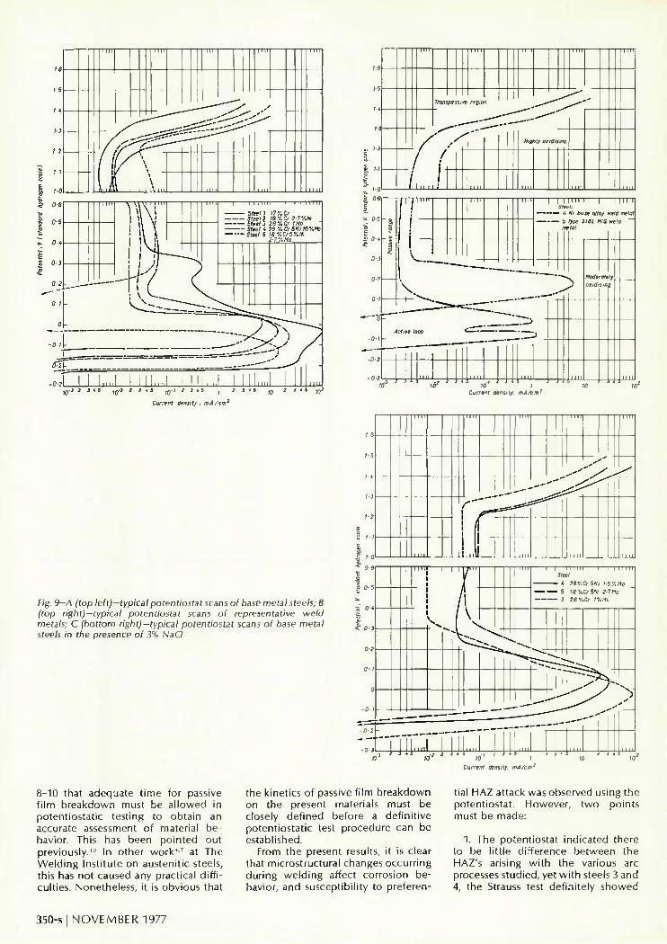
A n o d i c p o l a r i z a t i o n curves fo r t h e base meta ls and typ ica l n o n m a t c h i n g c o m p o s i t i o n w e l d meta ls are s h o w n in Fig. 9. These curves i l lus t ra te t he general co r ros ion behav io r o f t h e d i f fe ren t mater ia ls,7 and are g iven p r imar i l y for re fe rence. Regions of a t tack a n d passiv i ty are s h o w n .
It w i l l be n o t e d that unde r m o d e r ately o x i d i z i n g c o n d i t i o n s , the c r i t i ca l
Fig. 6-Microstructures of steel 5: A (top)-base metal, X125; B (middle)-weld metal and HAZ of SMA weld using 316L electrodes, X100; C (bottom)—fusion boundary crack in SA weld in steel 5 using nickel-base filler metal, X250 (50% reductions on reproduction)
po ten t i a l for a t tack o n any par t i cu la r w e l d area shou ld be as l o w as poss ib le . If, fo r e x a m p l e , the c r i t i ca l p o t e n t i a l for an H A Z is above that fo r t he base me ta l , w e l d i n g must be cons ide red to have had an adverse e f fec t o n t he co r ros ion resistance o f t he m a t e r i a l . ' 7
U n d e r h igh l y o x i d i z i n g c o n d i t i o n s , it
Table 6—Results of Strauss Tests on GTA Welds in Thin Sheet Materials
Steel
No. 1
No. 2
No. 3
Control
Strauss
C S C S c s
Bend test""
F F P P P F
Observation of crack
pos i t ion" "
Weld Weld No cracks No cracks No cracks HAZ and FB
Depth of penetration in mm/year
Weld HAZ
3.8 6.4
0.03 0.06
2.3 2.9
Base metal
0.06
0.03
0.19
Assessment
F
P
F
I-,F—fall; P-pass. ""Weld—weld metal; HAZ—heal affected zone; FB — fusion boundary.
344-s I N O V E M B E R 1 9 7 7

Table 7—Results of Strauss Tests for Plate Samples
Strauss test results Modi f ied Strauss
test results '"
Weld no. Process
SMA
2 SMA
3 SMA
4 GMA argon
GMA 5 argon
+ 1 % 0 2
6 GMA argon
7 GTA
8 GTA
9 GTA
10
11
12
SA
SA
SMA
SMA
SMA
SMA
SMA
SMA
GMA
GMA
Filler metal
Type 309L-MO
Type 316L
Ni-base
Matching composit ion
Matching composit ion
Ni-base
Matching composit ion
Matching composit ion
Ni-base
Matching composit ion
Ni-base
HAZ" " grain Control
Send Observations
of crack (ASTM) Strauss test"" posit ion
Steel 3, 26%Cr/1%Mo.
C P No cracks
Depth of penetration
mm/year
Depth of penetration,
mm/year
Matching composit ion
Matching composit ion
Type 316L
Type 316L
Ni-base
Ni-base
Near matching composit ion
Type 316L
2
2
2
1
> 1
> 1
1 and 2
1
1 and 2
1
1
> 1
1
3
1
1
1
3; 1 in TIG root
1
> 1
S
C
S
C
S
C
S
c s c s c s c s c s c s c s c s
c s c s c s c s c s c s c s c s
F
p
F
F
F
P
P
P
F
F
F
P
P
P
P
F
F
F
F
P
P
P
P
Fusion boundary
No cracks
Fusion boundary
No cracks
Fusion boundary
No cracks
No cracks
No cracks
HAZ and FB
Fusion boundary
Fusion boundary
No cracks
No cracks
No cracks
No cracks
HAZ and FB
HAZ and FB
Weld
Weld
Small tear in FB
Small tear in FB
No cracks
No cracks
Steel 4, 26%Cr/5%Ni/1.5%M
F Small crack defect
F
F
P
F
F
F
P
P
P
P
P
F
F
P
P
Weld
Weld
No cracks
Fusion boundary
Fusion boundary
Weld crack
No cracks
No cracks
No cracks
No cracks
No cracks
HAZ and FB
HAZ and FB
No cracks
No cracks
Weld metal HAZ'
0.03 1.3
Base Assess-metal ment
0.09
Weld Base Assess-metal HAZ" " metal ment " "
0.09
0.03
1.12 0.12
0.95 0.16
0.03 0.09 0.16
0.12 1.2
0.79 0.4
0.16
0.16
0.49 0.32 0.12
0.15 0.32 0.12
0.06 1.7 0.07
0.12 0.38 0.09
0.2 0.32 0.16
0.09 0.06 0.06
0.06 0.12 0.06
0.03 (1.12 0.32 0.06
(b)) 0.09 (1.74 0.29
(b)) 0.09 (0.47 0.22
(b»
0.1
0.09
0.06 0.15 0.06
0.03 0.03 0.03
0.06
0.03
1.3
0.12
0.06
0.03
0.09 • 1.8 0.63 F
(1.4)""
0.18 2.3 0.36 F
18.8 0.1 0.27 F
2.28 1.62 0.38 F
ND ND ND ND
1.35 0.95 0.9 F
0.1 0.95 0.95 P
0.09 0.47 0.57 P
ND ND ND ND
ND ND ND ND
0.19 0.45 0.27 P
0.18 0.09 1.2 P
0.63 (1.08)""
2.0 (5.2)""
0.18 (1.4)""
0.18 (0.9)""
2.07
0.72
0.57
1.99
1.35
1.17
0.27
0.09
0.27
1.62
0.54
P
P
F
F
F
15.93 0.54 0.1c
0.26 2.19 1.42
0.28 0.72 0.26 P
(Cont inued on next page)
is des i rab le tha t t he c r i t i ca l p o t e n t i a l for b r e a k d o w n o f passiv i ty be as h igh as poss ib le . Few service m e d i a o the r
t han n i t r i c ac id are su f f i c i en t l y h igh l y o x i d i z i n g fo r co r ros ion to o c c u r at t he " t o p " of t he passive range. Preferent ia l
in te rc rys ta l l i ne at tack in p rac t i ce is p r e d o m i n a n t l y associated w i t h the mode ra te l y o x i d i z i n g reg ime, and at-
WELDING RESEARCH SUPPLEMENT I 345-s
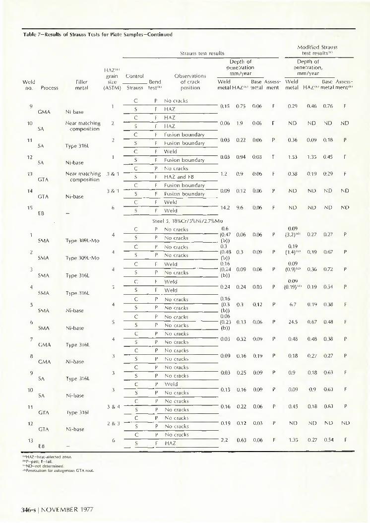
Table 7—Results of Strauss 1
Weld Filler no. Process metal
rests for Plate
HAZ"" grain size
(ASTM)
Samples—Contini
Control Rend
Strauss test11"
led
Strauss test
Observations of crack posit ion
results
Depth of penetration
mm/year
Weld Base metal HAZ'* ' metal
Assessment
Modi f ied Strauss test results"'1
Depth of penetration,
mm/year
Weld Base Assess-metal HAZ"*' metal ment " "
P No cracks
10
11
12
13
14
IS
GMA
SA
SA
SA
GTA
GTA
I B
SMA
SMA
SMA
SMA
SMA
SMA
ro
11
12
13
SA
SA
GTA
GTA
Ni-base
Near matching composit ion
Type 316L
Ni-base
Near matching composit ion
Ni-base
3 & 1
3 & 1
Type 309L-MO
Type 309L-MO
Type 3I6L
Type 316L
Ni-base
Ni-base
GMA Type 316L
GMA Ni-base
Type 316L
Ni-base
Type 316L
Ni-base
3 & 4
2 & 3
s c S
c S
c s c s c s c s
c s c s ( s c s c s c s c s c s c s c s c s c s c s
F
I
F
F
F
F
F
P
F
F
F
F
F
Stee
P
P
P
P
F
P
F
F
P
P
P
P
P
P
P
P
P
P
P
P
P
P
P
P
P
F
HAZ
HAZ
HAZ
Fusion boundary
Fusion boundary
Weld
Fusion boundary
No cracks
HAZ and FB
Fusion boundary
Fusion boundary
Weld
Weld
:l 5, 18%Cr/5%Ni/2.7%M
No cracks
No cracks
No cracks
No cracks
Weld
No cracks
We ld
Weld
No cracks
No cracks
No cracks
No cracks
No cracks
No cracks
No cracks
No cracks
No cracks
No cracks
Weld
No cracks
No cracks
No cracks
No cracks
No cracks
No cracks
HAZ
0.15 0.75 0.06 F 0.29 0.46 0.76 F
0.06 1.9 0.06 F ND ND ND ND
0.03 0.22 0.06 P 0.36 0.09 0.18 P
0.03 0.94 0.03 F 1.53 1.35 0.45 F
1.2 0.9 0.06 F 0.38 0.19 0.29 F
0.09 0.12 0.06 P ND ND ND ND
14.2 9.6 0.06 F ND ND ND ND
0.6 (0.47 (b)) 0.3 (0.48 (b)) 0.16 (0.24 (b))
0.24
0.16 (0.3 (b)) 0.06 (0.23 (b))
0.03
0.09
0.03
0.15
0.16
0.19
2.2
0.06
0.3
0.09
0.24
0.3
0.13
0.32
0.16
0.25
0.16
0.22
0.12
0.63
0.06
0.09
0.06
0.03
0.12
0.06
0.09
0.19
0.09
0.09
0.06
0.03
0.06
P
P
P
P
P
P
P
P
P
P
P
P
F
0.09 (3.2)"" 0.27 0.27 P
0.19 (1.4)"" 0.19 0.67 P
0.09 (0.9)"" 0.36 0.72 P
0.09 (0.19)"" 0.19 0.54 P
6.7 0.19 0.38 F
24.5 0.67 0.48 F
0.48 0.48 0.38 P
0.18 0.27 0.27 P
0.9 0.18 0.63 F
0.09 0.9 0.63 F
0.45 0.18 0.63 P
ND ND ND ND
1.35 0.27 0.54 F
•'HAZ-heat-affected zone. tt'P-pass; F-fail. "ND-not determined. "'Penetration for autogenous GTA root.
346-s I NOVEMBER 1977
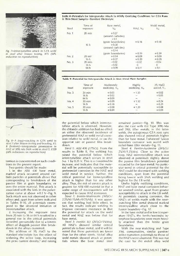
Table 8—Potentials for Intergranular Attack in Mildly Oxidizing Conditions for GTA Runs in Thin Sheet Samples—Standard Electrolyte
"5a--.i:- *® Fig. 7—Intercrystalline attack in CTA weld in steel alter Strauss testing, X75 (50% reduction on reproduction)
Fig. 8-A (top)-cracking in GTA weld in steel 3 after Strauss testing and bending, X5; B (bottom)-intergranular penetration in HAZ of 309L-Mo SMA weld in steel 3, X320 (50% reductions on reproduction)
tention is concentrated on such conditions in the present report.
Two points should be made: 1. In the AISI 430 base metal,
marked attack occurred around carbide particles at potentials above that corresponding to breakdown of the passive f i lm at grain boundaries, or over the entire material. This attack is associated wi th the kink in the polarization curve at above 4-0.3 V—Fig. 9. Such attack was not observed in other alloys and, apart from where indicated in Tables 8-10, all potentials correspond to the observed init iation of intercrystalline attack.
2. Increasing the exposure t ime from 20 min to 16 or 64 h resulted in a general rise in the critical potentials recorded, presumably due to a kinetic effect of sluggish passive fi lm breakdown in the alloys examined.
The addition of 3% NaCI to the standard electrolyte has the effect of widening the active loop, increasing the peak current density,9 and raising
Steel
No. 1
No. 2
No. 3
Table 9-Potcn
Steel
No. 3
No. 4
No. 5
Time of exposure
20 min
16 h
20 min 16 h
20 min 16 h 64 h
tial for Intergranu
Time of exposure
20 min 16 h 64 h 20 min 16 h 20 min 16 h
Base metal,
v„ + 0.27
(around carbides) + 0.1
(grain boundaries) + 0.38
(around carbides) + 0.14
(grain boundaries) + 0.14 + 0.27 -0.02 -0.02 + 0.09
lar Atfack in Base Metal
Moderately oxidizing, V,,
+ 0.03 + 0.03 + 0.09 + 0.09 + 0.18 + 0.08 + 0.09
HAZ, V„
+ 0.18
+ 0.39 + 0.09 + 0.20 -0.02
0 + 0.11
Plate Samples
Highly oxidizing, V n
+ 1.33
-—
+ 1.32
-+ 1.30
—
Weld metal,
v„
+ 0.18
+ 0.39 + 0.09 + 0.20 -0.04
0 + 0.1
3% NaCI added, VH
+ 0.02 + 0.05
-+ 0.24 + 0.29 + 0.08 + 0.09
the potential below which intercrystalline attack is observed. However, the chloride addit ion has had no effect on either the observed incidence of preferential HAZ or weld metal corrosion relative to weld metal, or on the apparent rate of passive fi lm breakdown.
Steel 7; A/5/ 430 (17%Cr). From the results in Table 8, the welding has raised the potential below which intercrystalline attack occurs in steel No. 1 by 0.25 V. This is a considerable increase, and indicates that the material wi l l be potentially susceptible to preferential corrosion in the HAZ and weld metal in service. Further, the critical potential for intercrystalline attack is higher than for any other alloy. Thus, the risk of service attack is greatest for AISI 430 material in that a wider range of environments wi l l be expected to cause HAZ corrosion.
Steel 2: Ferrite-Martensite (16%Cr/ 2.5%Ni/17oMo/0.5%Nb). It was apparent that welding had little effect. In fact, the results indicate welding to improve corrosion resistance in that the potential for attack on the weld metal and HAZ was below that for base metal.
Steel 3: Ferritic ELI (2670Cr/17oMo). All HAZ's showed similar critical potentials to base metal, and it wi l l be noted that these potentials are lower than for the other steels. Nickel alloy weld metals showed attack at potentials where the base metal steel
remained passive—Fig. 10. This was also the case wi th the Type 309L-Mo and 316L filler metals; in the latter welds, the autogenous GTA root runs also showed critical potentials higher than for base metal. Enhanced fusion boundary corrosion was noted wi th nickel-base filler metals—Fig. 11.
5tee/ 4: Ferrite-Austenite (26%G7 5%Ni/1.5%Mo). Close to the active loop, HAZ intercrystalline attack was observed at potentials slightly above the passive fi lm breakdown potential recorded for the base metal. No particular trend in critical potential for the HAZ could be discerned wi th welding conditions, apart from the potential being lowest wi th SMA welding and highest for the EB weld.
Under highly oxidizing conditions, HAZ and base metal corrosion behavior seemed similar, apart from greater susceptibility to attack in the EB weld. At potentials causing corrosion, the HAZ's of welds made wi th the near-matching filler metal showed marked intercrystalline attack close to the fusion boundary—Fig. 12.
In the base metal and in low temperature HAZ's, the ferrite/austenite interphase boundaries were more heavily attacked than the ferrite grain boundaries.
With the near-matching and Type 316L consumables, similar passive/ active transition potentials to those of the HAZ's were observed. This was not the case for the nickel alloy weld
W E L D I N G RESEARCH SUPPLEMENT I 347-s

Table 10—Potentials for Intergranular Attack in Plate Samples
Weld no.
1
2
3
4
5
6
7
8
9
10
11 12
Process
SMA
SMA
SMA
GMA argon GMA
A + 1 % 0 . GMA argon GTA
GTA
GTA
SA
SA EB
Filler metal
Type 309L-MO
Type 316L
Ni-base
Matching composit ion
Matching composit ion
Ni-base
Matching composit ion
Matching composit ion
Ni-base
Matching composit ion
Ni-base
SMA
2
3
4
5
6
7
SMA
SMA
SMA
SMA
SMA
GMA
Matching composit ion
Type316L
Type 316L
Ni-base
Ni-base
Matching composit ion
Time of exposure HAZ"
Steel 3, 26%Cr/1%Mo
20 min +0.04 16 h +0.04
20 min +0.03 16 h +0.03
20 min +0.04" 16 h +0.04 r
20 min -0 .1 16 h +0.03
20 min +0.03 16 h ND
20 min -0.02 16 h +0.02'
20 min 0.01 16 h 0
20 min 0 16 h 0.04 64 h 0.06
20 min -0.02 ND
20 min 0.02 16 h 0.06
20 min 0.01c' 20 min -0.03
Steel 4, 26%Cr/5%Ni/1.5%Mo
Matching composit ion 20 min +0.13 16 h +0.19
20 min +0.11 16 h +0.16
20 min +0.14 16 h +0.22
20 min +0.13 16 h +0.19
20 min +0.12 16 h +0.19
20 min +0.11 16 h +0.21
20 min +0.13 16 h +0.21
Standard electrolyte V „ 3% NaCI added, V„
WM« HAZ" W M "
+ 0.13b
+ 0.15 + 0.14"
0.18" 0.38e
0.38'' 0
+ 0.05 + 0.05 ND
+ 0.31 + 0.36
0.01 0 0.01 0.04 0.06
+ 0.28 ND 0.02 0.01
+ 0.30 -0.03
+ 0.12 + 0.19
+ 0.11 + 0.20 + 0.12 + 0.21
+ 0.13 + 0.19 + 0.39 + 0.40 + 0.39 + 0.38 + 0.13 + 0.20
+ 0.05 ND
+ 0.08 ND
+ 0.04 ND
+ 0.03 ND
+ 0.01 + 0.05 + 0.02 + 0.05
0 + 0.06 + 0.03 ND ND
+ 0.08 + 0.05 + 0.05 ND
+ 0.08 + 0.02
+ 0.18 + 0.25
+ 0.19 + 0.26 + 0.32 + 0.39
+ 0.29 + 0.38 + 0.26 ND
+ 0.27 ND
+ 0.23 + 0.33
(Cont inued on
•I-0.20 ND
+ 0.23 ND
+ 0.56 ND
+ 0.03 ND
+ 0.02 + 0.05 + 0.43 + 0.50
0 + 0.06 + 0.03 ND ND
+ 0.42 + 0.47 + 0.06
ND + 0.45 + 0.02
+ 0.19 + 0.25
(0.27)"" + 0.18 + 0.25 + 0.32 + 0.38
( + 0.40)"" + 0.30 + 0.32 + 0.56 + 0.60 + 0.56 + 0.62 + 0.22 + 0.31
next page)
meta ls , w h i c h we re cons i s ten t l y at tacked at a b o u t 200 m V h igher t h a n t h e o thers . There was some p r o p e n s i t y f o r m o r e rap id at tack t o o c c u r at t he fus ion bounda r ies o f w e l d s m a d e using n o n m a t c h i n g c o n s u m a b l e s than e l sewhere in t he samples e x a m i n e d and fo r a u t o g e n o u s GTA roo t runs also to s h o w an increase in co r ros i on rate.
5tee/ 5; Ferrite-Austenite (78%Cr/ 57oNi/2.77oMo). Observations made are largely similar to those for steel 4. Under moderately oxidizing conditions, the critical potentials for attack on the HAZ's, or stainless steel weld metals, were above the potential obtained for base metals, wi th autogenous GTA root runs tending to corrode more rapidly.
The EB weld showed greatest susceptibil ity to attack. Again, the corrosion characteristics of nickel alloy weld metals differ from those of the base metal. Ferrite/austenite interface attack was less marked than wi th steel 4, wi th attack on the austenite phase being more apparent.
Discussion
Welding Characteristics
Overall, the base metals studied are similar to austenitic stainless steels with regard to carrying out the welding operation per se. Some lack of fusion defects was observed in the test welds, especially at low heat inputs. However, the fusion and penetration characteristics of the materials examined were comparable to those of austenitic stainless alloys. Consequently, conventional stainless steel welding techniques can be considered to be directly applicable to the present alloys.
From the welding viewpoint, the greatest difference between the present materials and common austenitic grades is the increased risk of weld metal cracking in the former case. Cracking was found wi th both matching and nickel-base filler metals, the morphology generally indicating the cracks to have formed during solidif ication. In nickel-alloy weld deposits,
cracks apparently initiating at the fusion boundary were frequently observed.
Typical crack lengths were of the order 0.5-1.0 mm (0.02 to 0.04 in.). While the cracks may not be of practical significance, this observation does mean that careful consideration must be given to the use of nickel alloy filler metals for the stress corrosion resistant stainless steels examined. There was no evidence that such cracking was dependent on welding conditions. Also, it would appear to stem from the formation of a region having a crack-sensitive composit ion as a result of di lut ion of the filler metal by a low-nickel base metal.
In the fully ferritic steel 3, weld metal cracks in submerged arc welds made using matching composit ion filler metals appeared to have formed by cleavage at low temperature. It is well established that the toughness of fully ferritic stainless steels is highly dependent on material purity/1 and some pick-up of interstitial elements
348-sl N O V E M B E R 1977

Table 10-Potentials for Intergranular Attack in Plate Samples-Continued
Weld no.
8
9
10
11
12
13
14
15
1
2
3
4
5
6
7
8 9
10
11
12
13
Process
GMA
GMA
SA
SA
SA
GTA
GTA
EB
SMA
SMA
SMA
SMA
SMA
SMA
GMA
GMA SA
SA
GTA
GTA
EB
Filler metal
Type 316L
Ni-base
Matching composi t ion
Type 316L
Ni-base
Matching composi t ion
Ni-base
Steel 5,
Type 309L-Mo
Type 309L-MO
Type 316L
Type 316L
Ni-base
Ni-base
Type 316L
Ni-base Type 316L
Ni-base
Type 316L
Ni-base
—
Time of exposure
20 min 16 h
20 min 16 h
20 min 16 h
20 min 16 h
20 min 16 h
20 min 16 h
20 min 16 h
20 min
18%Cr/5%Ni/2.7%Mo
20 min 16 h
20 min 16 h
20 min 16 h
20 min
20 min 16 h
20 min 16 h
20 min 16 h
20 min 20 min
16 h 20 min
16 h 20 min
16 h 20 min
16 h 20 min
16 h
M d l l U d t U eifc
HAZ"
+ 0.12 + 0.28 + 0.12 + 0.29 + 0.14 + 0.35 + 0.16 + 0.23 + 0.12 + 0.27 + 0.09 + 0.25 + 0.09 + 0.35 + 0.26
+ 0.13 0.13
+ 0.14 + 0.18 + 0.13 + 0.16 + 0.13 + 0.18 + 0.18 ND
+ 0.14 + 0.15 + 0.12 + 0.19 + 0.14 + 0.12 + 0.20 + 0.12
ND + 0.10 N D
+ 0.12 ND
+ 0.30 + 0.45
cuoiy ie v H W M "
+ 0.14 + 0.19 + 0.31 + 0.30 + 0.14 + 0.19 + 0.18 + 0.23 + 0.35 + 0.30 + 0.09 + 0.30 + 0.32 + 0.40 + 0.65
+ 0.14 0.14
+ 0.17 + 0.19 + 0.16 + 0.17 + 0.17 + 0.17 + 0.38 + 0.38 + 0.37 + 0.39 + 0.17 + 0.20 + 0.36 + 0.17 + 0.17 + 0.29 ND
+ 0.12 N D
+ 0.27 ND
+ 0.60 + 0.63
J/O I N d C I <J
HAZ"
+ 0.31 + 0.34 + 0.23 ND
+ 0.22 + 0.33 + 0.30 + 0.31 + 0.23 + 0.34 + 0.16 + 0.28 + 0.27 + 0.33 + 0.26
+ 0.22 + 0.28 + 0.22 + 0.27 + 0.25 + 0.31 + 0.26 + 0.31 + 0.28 ND
+ 0.26 ND
+ 0.20 + 0.25 + 0.28 + 0.22 + 0.26 + 0.30 + 0.26 + 0.21 + 0.24 + 0.33 + 0.26 + 0.38 + 0.50
uueu, v || W M "
+ 0.30 + 0.33 + 0.54 + 0.55 + 0.24 + 0.31 + 0.33 + 0.33 + 0.59 + 0.69 + 0.18 + 0.30 + 0.44 + 0.45 + 0.45
+ 0.22 + 0.28 + 0.22 + 0.27 + 0.25 + 0.32 + 0.23 + 0.31 + 0.56 ND
+ 0.56 + 0.63 + 0.23 + 0.27 + 0.42 + 0.24 + 0.28 + 0.44 + 0.48 + 0.24 + 0.27 + 0.48 + 0.51 + 0.38 + 0.58
"HAZ-heat-affected zone; WM-weld metal "Attack below this potential on both autogenous GTA and bulk weld metal. •Attack most apparent at fusion boundary.
"Critical potential for GTA root runs.
during submerged arc welding must be anticipated, with consequent decreased capacity for accepting welding strains wi thout cracking. Such an effect of contamination is consistent wi th results of other workers. Unless special consumables can be developed, the submerged arc process cannot be recommended for this material.
Steel 3 also showed HAZ cracking. As in the submerged arc weld metal the cracks appeared brittle, and to have formed at low temperature.
Evaluation of Corrosion Test Methods
Susceptibility to intercrystalline attack was found wi th the Strauss test. In principle, the method appears as applicable to the present alloys as it is to austenitic steels. In a number of instances, test welds showed poor bend ductil ity. However, discrimina
t ion between different weld areas was successfully obtained by the use of metallographic examination to define the depth of penetration during exposure to the acid copper sulphate. At the same time, it may be noted that intergranular attack in the Strauss test electrolyte takes place only in areas heated too close to the solidus temperature during welding. Hence, attack is extremely localized and, in an HAZ, may arise over only a few grain diameters from the fusion boundary. Careful examination is necessary to locate and measure such intergranular penetration. Moreover, the procedure cannot be regarded as a straightforward standard test method, as is the normal procedure called for in BS 1449: Part 4. 1967.
In ascribing a "pass" or " fa i l " assessment to the welds tested by the Strauss method, consideration is given both to the observed bend behavior, and to
the rates of penetration recorded. It wi l l be noted that, especially with the modif ied procedure, appreciable attack could take place on base metal and that the rate of such attack showed considerable variation—Table 7. This has to be borne in mind when deciding whether or not a welding operation has significantly increased the risk of intercrystalline corrosion.
The practical application of data generated from a standard test procedure such as the Strauss test wi l l depend on the view taken of the relevance of the test to anticipated service conditions. In this regard, reference wi l l probably be made to whether or not a history exists of intercrystalline attack in welded austenitic alloys.
In principle, it is advantageous to employ a test method capable of giving information pertinent to as wide a range of environments as possible. However, it is clear from Tables
W E L D I N G RESEARCH SUPPLEMENT I 349-s
!
/>->>--—
I \{/\ J \ \,
"^x* -—— ^'yA-'^-''A
"._ •*
oe
o-a
0 <
0 3
0 2
0 1
0
- 0 ,
. i i i
11 'ML
i i rr-1
i 1 Jl
AT ? — • _ — —
• •
• Steel 1 • Steel 2
17% Cr 16'/.Cr 2-7'ANi
Steel i 26 "/. Cr 5/V; K V.Mo Steel 5 18 '/.CrS'/.Ni
2-7V.M0
-^"—-~i>—~
. J\A~~
i in..,.! ! IH....I : ' ...I i III.„J u n ,-J 2 J 4! ,„-2 2 1 «5 ,„•> J 3 45 JO ' 3 t $ to2
Current density , mA/cm2
Fig. 9—A (top left)—typical potentiostat scans of base metal steels; B (top right)—typical potentiostat scans of representative weld metals; C (bottom right)—typical potentiostat scans of base metal steels in the presence of 3% NaCI
1
1
/
Tronspa ss i ve region
1 111
^ < ^ " ___ — • " _ ' _ C ^ - ^ " '
-̂ V" i ( In i
1 1
Highly oxidising
l l l l
""
i- 0-5
0-3
0-1
-0-2
St a
S,
i i ! 1
11 MM
i \
'
l l l l ! 1 '
* -——**
—^s-^-:=i.^r._ Active loop C— ,.
r*J ' A 2
1 1 1 HI Steel. • 4 Ni ba
1
se alloy
i n i " veld metal
• 5 Type 316L MIG weld metal
J Moderate oxidism
ty 7
Current density, mA/cm2
1 111
/
1 i, nil
„ - - - '
= = ~ ^
11 n
' - ' ^ ^ i |
m i
OS
OS
ot
0-3
02
0-1
0
0-1
11
/I
:i;:^>.-
l l l l 1 : 1 1 1 II Steel
I I 11
5 IS V.Cr 5 * 2-7Mo 3 26'/.Cr t'/.Mo
^̂ "̂ *
— ̂
1
i ^ ^ . ̂
III....I ' •,-* ' .
1
Current density. mA/cm2
8-10 that adequate time for passive f i lm breakdown must be allowed in potentiostatic testing to obtain an accurate assessment of material behavior. This has been pointed out previously."1 In other w o r k " at The Welding Institute on austenitic steels, this has not caused any practical diff iculties. Nonetheless, it is obvious that
the kinetics of passive fi lm breakdown on the present materials must be closely defined before a definitive potentiostatic test procedure can be established.
From the present results, it is clear that microstructural changes occurring during welding affect corrosion behavior, and susceptibility to preferen
tial HAZ attack was observed using the potentiostat. However, two points must be made:
1. The potentiostat indicated there to be little difference between the HAZ's arising wi th the various arc processes studied, yet w i th steels 3 and 4, the Strauss test definitely showed
350-s I NOVEMBER 1977

Fig. 10—Preferential attack on nickel-base SMA weld metal following exposure to + 0.2V,, for 76 hours: steel 3, 13 mm (0.5 in.) thick base metal and autogenous GTA root run, unattacked, X5 (50% reduction on reproduction)
welding procedure to influence susceptibil ity to intercrystalline attack.
2. Wi th nickel-base weld metals, the critical potentials for intercrystalline HAZ attack lay wi th in the potential range, causing weld metal corrosion; hence, under moderately oxidizing conditions, environments causing HAZ penetration should also cause weld metal attack.
This was not the case, since negligible weld metal attack was found on Strauss test samples which were susceptible to HAZ corrosion (although weld metal corrosion was observed wi th the modif ied Strauss procedure). It must, therefore, be concluded that the potentiostatic technique for evaluating sensitivity to intergranular attack as developed for plain 18%Cr/10%Ni type austenitic steels7 is insufficiently sensitive to give a definit ive assessment of susceptibility with the present steels.
At least wi th steels 3 and 4 the critical potentials for base metal or HAZ attack close to the active loop were higher wi th longer exposure. This was not the case with nickel-base weld metals, which showed consistent breakdown potentials. This latter behavior is similar to that found previously for austenitic steels.7 Thus, there seems no reason to doubt the applicability of the potentiostatic test procedure to nickel-base weld metals.
The relative merits of the potentiostat and Strauss test have been considered elsewhere.'" Essentially, they measure slightly different parameters. The potentiostat determines whether or not susceptibility to intercrystalline corrosion exists, and if so, over what potential range such corrosion can occur. On the other hand, the Strauss tests gives an indication of the rate of attack associated wi th any susceptibility that may exist. For the present, particular attention should be paid to the Strauss test, pending development of a potentiostatic test procedure in which full allowance is made for passive f i lm breakdown.
Fig. 11—Preferential fusion boundary attack in weld in Fig. 10, following exposure for 20 min at + 0.04V,,, X200 (50% reduction on reproduction)
Comparison of Materials
The salient feature of the data in Tables 8-10 is that steels 2-5 suffer less susceptibility to intergranular attack on welding than does steel 1. This was found by both the potentiostat and Strauss tests, and indicates that these recently developed alloys wil l be less sensitive to local loss of corrosion resistance when used in welded fabrications than wi l l the traditional AISI 430 material. Steels 2-5 wil l also show advantages in improved general corrosion resistance over AISI 430, although differences between them must be anticipated in some service media.
From the corrosion tests carried out, three observations in particular can be made:
1. Under the conditions of tests employed, corrosion resistance is least affected by welding wi th steels 2 and 5. No appreciable sensitization to intercrystalline attack was observed in the arc welds studied, only the electron beam weld in steel 5 failing the Strauss test.
2. Both steels 3 and 4 can be welded wi thout inducing susceptibility to preferential intergranular attack in the HAZ or weld metal, but attention to welding procedure is required.
3. The corrosion resistance of the nickel-base weld metals studied is not identical to that of the base metals. These weld metals have narrower passive ranges; they can be expected to suffer preferential attack in some environmental conditions, especially those corresponding to potentials close to the active loop.
Steel 2 is stablized with niobium, and it would seem that this approach is effective in avoiding intercrystalline attack, at least in the thin section size examined. It is probable that intercrystalline corrosion in the materials examined arises as a result of chromium carbide (and nitride) precipitation and local chromium depletion, in an analogous manner to that in austenitic stainless steels."1,1 Indeed, a number of workers have studied the effect of traditional stabilizing elements.'°' ia
The present data support this view
Fig. 12-HAZ of CTA weld in steel 4 with near-matching filler metal showing precipitation and attack at grain boundaries, X320 (50% reduction on reproduction)
insofar as the potential range over which intercrystalline attack was observed—and the range corresponds to that in which attack on low chromium regions wil l occur. On this basis, the relatively good behavior of steels 4 and 5 can be directly ascribed to the relatively large ferrite/austenite interphase boundary area; chromium carbide and nitride precipitation wil l occur at the interphase boundaries as well as at grain boundaries and the density of precipitation and resultant chromium depletion wil l be reduced.
Susceptibility to intergranular attack in steels 4 and 5 was associated wi th a coarse predominantly ferritic structure. The greater tendency of steel 4 to transform to ferrite during the welding cycle is presumably largely responsible for the greater sensitivity of this alloy to a welding operation.
In this context, intercrystalline attack has been reported in steel 5 (and to a lesser extent in steel 4) under saline conditions." Subsequent to such attack being observed, more nitrogen has been added to steel 5 to reduce its ferrite-forming tendency. From the present results on current production analysis material, this compositional modification has been successful in avoiding susceptibility to intercrystalline attack, at least in multipass arc welds in the section size examined.
In steel 4, satisfactory joint corrosion resistance was obtained wi th the SMA and GMA processes and a Type 316L stainless steel filler metal. However, the use of a near matching filler metal consistently gave reduced HAZ corrosion resistance. It has been noted elsewhere that the choice of filler metal can influence HAZ corrosion resistance in stress corrosion resistant stainless alloys.1" The effect apparently arises because of diffusion of deleterious elements, especially interstitial elements, from the weid metal to a predominantly ferritic HAZ during the welding operation. On this basis, the problem can be ameliorated in steel 4 by attention to consumable composit ion. It may be possible to improve
WELDING RESEARCH SUPPLEMENT I 351-s

matters by promoting austenite formation in the HAZ, either by control l ing the cooling rate or by using a postweld heat treatment.
The tendency to form ferrite in steel 4 was highest in autogenous GTA root runs and on EB welding; increased susceptibility to intercrystalline attack was observed in both these situations. Electron beam welding would seem to be of l imited application to this alloy, unless postweld heat treatment can be applied. Wi th autogenous GTA runs it would be recommended that a sealing run be employed, or that the root run should not be exposed to aggressive conditions.
The cause of failure of the GTA weld in thin gauge steel 3 is not clear, although an earlier footnote regarding material composition should be noted. There is ample evidence from the results of other recent investigations on steel 3 that stringent control of welding procedure is essential to avoid any contamination.3141" Hence, most satisfactory results were presently obtained wi th 13 mm (0.5 in.) thick plate using gas shielded arc or electron beam welding, with matching composition filler metal in the former case.
Other workers have found failure on Strauss testing welds in this alloy made using Type 316 stainless steel and nickel-base filler metals in material thicknesses of several millimeters. There seems litt le doubt that the alloy is highly sensitive to HAZ "contaminat ion" from nonmatching composit ion weld metal, and control of contamination rather than the final microstructure would appear to be the more important factor in maintaining corrosion resistance on welding.
Practical Implications
The steels examined in this paper were developed to have corrosion resistance equivalent to that of common austenitic grades. Especially wi th steel 3, it is likely that each wi l l offer specific advantages'in resisting attack in some media.17 However, in the first instance, they wil l probably be specified for applications where the stress corrosion resistance of austenitic alloys has proven inadequate. Particularly wi th the duplex materials, austenitic stainless steel filler metals have commonly been recommended on the basis of weldment corrosion and mechanical properties.2-'s
Dilut ion from base metals increases the ferrite contpnt typically to about 25%.18 However, because such weld metal contains austenite as the major phase, it is possible that a continuous path for SCC propagation may exist through the deposit. Hence, it has been considered desirable to employ nickel alloy filler metals, on the basis
that the high nickel content wi l l render the weld metal immune to chloride-induced SCC.
This use of nickel-base weld metal must be questioned on the basis of two sets of reasons:
1. The weld metal corrosion resistance is not necessarily equivalent to that of base metal; in many situations, this wi l l not matter since both weld and base metal wi l l be sensibly passive. However, a risk of preferential weld metal corrosion in some media must be accepted. The use of molybdenum-containing nickel consumables may improve matters, in view of the effect of this element in promoting passivity under moderately oxidizing conditions.1"
2. The use of nickel-base weld metals increases the risk of weld metal cracking, and in this regard the nickel-base weld metals do not confer immunity from SCC.
It has been found that, because of di lut ion, a zone can be formed at the fusion boundary which is fully austenitic. However, this zone contains substantially less than the 40% nickel generally considered necessary to avoid SCC, and tests have shown that SCC along this zone can occur.16-20
At the present state of the overall test program, it is premature to make definitive welding recommendations for the alloys under investigation. However, on the basis of the corrosion tests carried out, the fol lowing comments can be made: Each steel can be welded to give satisfactory results, but it would appear that steel 5 is least affected by a welding operation. The near-matching filler metal used for steel 4 was not employed wi th steel 5 so that the effect of this particular consumable on the HAZ behavior of the latter alloy was not established. Nonetheless, nonmatching consumables were employed wi th no apparent effect, indicating that steel 5 offers considerable flexibility regarding choice of welding procedure.
The single pass EB weld showed some loss of properties in the section size studied. A similar effect may occur in principle wi th arc welding if a mul t i pass procedure is not employed to give structural refinement in the HAZ. Thus, it wi l l be necessary in future work to evaluate the effect of higher input energy welding conditions as may be used in practice to obtain increased deposition rates.
The results obtained indicate that steel 4 wi l l be most satisfactorily welded using austenitic stainless steel filler metals and any multipass arc process. However, attention must be given to the possible adverse behavior of an autogenous GTA root run. It has
been demonstrated by other workers that steel 3 can be welded in thicknesses of up to 12 mm (0.47 in.), wi th satisfactory results.3151"-21 However, it is clear that stringent attention must be paid to avoiding contamination during welding, and, indeed, a close parallel can be drawn between steel 3 and t i tanium. Thus, gas shielded arc or electron beam welding must be regarded as essential for this alloy.
At the present t ime, the commercial future of steel 2 is uncertain. However, accepting that only thin section material was studied, the high resistance to intercrystalline attack shown after welding is noteworthy. Consequently, there would appear to be scope for development of stress corrosion resistant alloys based on a ferrite-marten-site structure.
Conclusion
A study was carried out on recently developed stress corrosion resistant stainless steels to examine the effect of welding on intergranular corrosion resistance. This was done wi th particular reference to moderately oxidizing environmental conditions. The materials examined were AISI 430 (steel 1, included for comparative purposes), a ferritic-martensitic steel (steel 2), an extra low interstitial fully ferritic alloy (steel 3), and two ferritic-austen-itic: materials (steels 4 and 5). The fo l lowing conclusions were reached:
1. All the new alloys examined showed advantages over conventional AISI 430 material wi th respect to corrosion resistance after welding.
2. Steel 2 containing 16%Cr/2.5%Ni/ 1%Mo/0.5%Nb showed no susceptibility to intergranular corrosion after GTA welding, although only thin gauge sheet was examined.
3. Opt imum results on steel 3 containing 26%Cr/1 %Mo were obtained with gas shielded arc or electron beam welding, where contamination of the weld area was minimal. In both steels 3 and 4, choice of consumable could influence HAZ behavior.
4. The behavior of steel 4 containing 26%Cr/5%Ni/1.5%Mo was broadly comparable wi th that of steel 5. Some reduction in bend ducti l i ty and corrosion resistance was noted in a number of welds examined, but satisfactory results were obtained using the SMA and GMA processes wi th Type 316L stainless steel filler metals.
5. Steel 5 containing 18%Cr/5%Ni/ 2.7%Mo was little affected by welding under the conditions employed. Corrosion resistance similar to that of base metal was obtained using Type 316L or 309L-Mo stainless steel filler metals and a range of arc processes. Electron beam welding caused some loss of
352-sl NOVEMBER 1977

b e n d d u c t i l i t y , and i n d u c e d suscep t i b i l i t y to in te rc rys ta l l i ne at tack.
6. The co r ros i on behav io r o f the n icke l a l loy w e l d meta ls s t u d i e d was no t i den t i ca l t o tha t o f t he base meta ls . In many e n v i r o n m e n t a l c o n d i t i o n s t he d i f f e rence w i l l no t be s ign i f i can t , bu t a risk o f p re fe ren t ia l w e l d m e t a l c o r r o sion in m o d e r a t e l y o x i d i z i n g m e d i a w i t h n icke l a l l oy f i l le r meta ls mus t be cons ide red .
7. W e l d meta l c rack ing was f o u n d w i t h steels 3-5. This was par t i cu la r l y n o t e d w i t h n i cke l -base f i l ler meta ls , i n i t i a t i ng at the fus ion b o u n d a r y . In a d d i t i o n , steel 3 s h o w e d some suscept i b i l i t y to b r i t t l e H A Z c rack ing .
Ac/cnow/edgements
The au thors t h a n k the i r co l leagues at The W e l d i n g Ins t i t u te fo r the i r adv ice and expe r imen ta l assistance. Thanks are also g iven to t h e Research M e m b e r C o m p a n i e s of The W e l d i n g Ins t i tu te w h o s u p p l i e d mate r ia l for e x a m i n a t i o n .
References
1. Castro, R., and de Cadenet, J. J., The Welding Metallurgy of Stainless and Heat Resisting Steels, Cambridge University Press, Cambridge, 1974.
2. Blom, U., and Helmer, C , "The Corrosion Resistance of SANDVIK 3RE60 Versus
Austenitic Chromium-N icke l Steels and Ferritic Chromium Steels," SANDVIK Report 71-0201 33-11E, 1971.
3. Matejka, W. A., and Knoth, R. J., "A High Purity Approach to High Chromium Ferritic Stainless Steels," /. Testing and Evaluation, 3 (3), May 1975, pp. 199-207.
4. Gooch, T. C , and Wi l l ingham, D. C , Weld Decay In Austenitic Stainless Steels, The Welding Institute, Abington, Cambridge, 1975.
5. Polgary, S., "Resistance to Intercrystalline Corrosion in Stainless Steel Weld Metal , " Svetsaren (English Edit ion), 8 (1-2), 1972, pp. 2-12.
6. ASTM Standard A262-70, Modi f ied Practice E.
7. Gooch, T. G., "Corrosion of AISI Type 304 Austenitic Stainless Steel," Brit. Weld, j., 15 (7), July 1968, pp. 345-357.
8. Henrikson, S., and Knutsson, L., "Corrosion Tests In Baltic Seawater On Heat Exchanger Tubes of Various Metal l ic Materials," Br. Corros. j., 10 (3), 1975, pp. 128-135.
9. Riggs, O. L., Jr., "Effects of Hydrogen Halides on Anodic Polarisation of Stainless Steel," Corrosion, 19, (5), May 1963, pp. 180t-185t.
10. Gooch, T. G., "We ld Decay: The Assessment of Susceptibil ity," Weld ing Institute Research Bulletin, 10 (11), Nos. 1969, pp. 287-292.
11. Rarey, C. R., and Aronson, A. H., "Pitt ing Corrosion of Sensitised Ferritic Stainless Steel," Corrosion, 28 (7), July 1972, pp. 255-258.
12. Hodges, R. I., "Intergranular Corrosion In High Purity Ferritic Stainless Steels,"
Corrosion, 27 (3), March 1971, pp. 119-127 and Ibid., 27 (4), April 1971, pp. 164-167.
13. Bond, A. P., "Mechanisms of Intergranular Corrosion in Ferritic Stainless Steels," Trans. Met. Soc, AIME 245, Oct. 1969, pp. 2127-2134.
14. Steigerwald, R. F., " N e w Molybdenum Stainless Steels For Corrosion Resistance: A Review of Recent Developments," Mat. Pert, 13 (9), Sept. 1974, pp. 9-16.
15. Wright, R. N., "Mechanical Behaviour and Weldabi l i ty of a High Chromium Ferritic Stainless Steel As a Function of Purity," Welding journal, 50 (10), Oct. 1971, Res. Suppl., pp. 434-s to 440-s.
16. Lowrie, R„ "Weld ing E-Brite 26-1 to Other Alloys," Weld ing Journal, 52 (11), Nov. 1973, Res. Suppl., 500-s to 506-s.
17. Di l lon, C P., "Use of Low Interstitial 26Cr-1Mo Stainless Steel in Chemical Plants," Mat. Pert., 14 (8), Aug. 1975, pp. 36-37.
18. Carlen, J, C , "Fabrication Plant in SANDVIK 3RE60," SANDVIK Report No. 71 0201 52-31 E.
19. Shaw, D., and Edwards, M., "A Transistorised Potentiostat System for Corrosion Studies," Corrosion Science, 5 (6), June 1965.
20. Nordin, S., "Observations Regarding Stress Corrosion Phenomena in an Auste-no-Ferritic Stainless Steel," Uddeholm Steel Research Report, Achema-Congress, Frank-furt-am-Main, 1973.
21. Dorschu, K. E., "Weldabi l i ty of a New Ferritic Stainless Steel," Welding journal, 50 (9), Sept. 1971, Res. Suppl., pp. 410-s to 418-
WRC Bulletin 229 August 1977
(1) Dynamic Fracture-Resistance Testing and Methods for Structural Analysis
by E. A. Lange
The potent ia l fo r the in i t i a t ion of f as t f r ac tu re can be p red ic ted by the recent ly developed techno logy of l inear elast ic f r ac tu re mechan ics (LEFM) wh ich has p roduced the basis for an ana ly t ica l app roach to f rac tu re res is tance and s t ruc tu ra l in tegr i ty . To m a k e f r ac tu re mechan i cs a v iab le eng inee r i ng des ign too l , emp i r i ca l cor re la t ions between pract ica l d y n a m i c tes t resul ts a n d the basic pa rame te rs are needed. In th is paper the a t t r i bu tes and l im i ta t i ons of the Charpy , Drop Weight -N i l Duct i l i ty T rans i t i on T e m p e r a t u r e , Drop Weight Tear, a n d Dynamic Tear tes ts are d iscussed w i t h respect to p rov id i ng i n f o r m a t i o n usefu l in s t ruc tu ra l in tegr i ty analyses.
(2) Junction Stresses for a Conical Section Joining Cylinders of Different Diameter Subject to Internal Pressure
by W. J. Graff
The conica l t r ans i t i on sect ion of a cy l indr ica l pressure vessel was i n s t r u m e n t e d inside and ou ts ide w i th electr ic res is tance s t ra in gages, and f r o m the l ong i t ud ina l a n d c i r c u m f e r e n t i a l s t ra ins measured exper imenta l l y , the co r respond ing stresses were d e t e r m i n e d . The resul ts were c o m p a r e d w i th ca lcu la ted stresses f r o m the theory of shel ls. The exper imen ta l l y d e t e r m i n e d st resses exceeded code m e m b r a n e stresses in the i m m e d i a t e v ic in i ty of t he j unc t i ons .
Pub l ica t ion of th is paper was sponsored by t he We ld ing Research Counc i l .
The pr ice of WRC Bul le t in 2 2 9 is $ 7 . 5 0 per copy. Orders shou ld be sen t w i t h p a y m e n t to t he We ld ing Research Counc i l , Un i ted Eng ineer ing Center , 345 East 4 7 t h Street , New York , NY 10017 .
W E L D I N G R E S E A R C H S U P P L E M E N T I 353 -s