![A-BEAM S...EN ISO 5817 Welding. Fusion-welded joints in steel, nickel, titanium and their alloys. [11] EN 17760-1 Welding. Welding of reinforcing steel. Part 1: Load-bearing welded](https://static.fdocuments.net/doc/165x107/5fda3e822907c8417b043b87/a-beam-s-en-iso-5817-welding-fusion-welded-joints-in-steel-nickel-titanium.jpg)
Interfacial Investigation of Explosion-Welded Titanium ...
9
Interfacial Investigation of Explosion-Welded Titanium/ Steel Bimetallic Plates Qiaoling Chu, Xiongwei Tong, Shuai Xu, Min Zhang, Jihong Li, FuXue Yan, and Cheng Yan (Submitted November 9, 2019; in revised form December 12, 2019; published online December 23, 2019) Commercial pure titanium and low carbon steel were explosive welded. The interfacial structures were examined using a combined microstructural analysis and nanoindentation tests. The interface has a wavy morphology with an isolated mixing zone where a mixing of elemental titanium (Ti) and iron (Fe) occurs. Constituents in the mixing zone vary even under the same explosive welding conditions; for example, some are dominated by Fe 2 Ti intermetallics, whereas some consists of Fe 2 Ti and FeTi intermetallics. The nanoindentation tests and fracture observation confirm the brittle nature of the Fe-Ti intermetallics that formed in the mixing zone. The FeTi phase ( 20.3 GPa) showed higher hardness than the Fe 2 Ti phase ( 14.2 GPa). Simple approaches to estimate the cooling rate at the Ti/steel interface are proposed, and the calculated rate is 2.1 3 10 7 K/s. Such a high cooling rate combined with the chemical compositions results in the formation of the nanoscaled Fe 2 Ti structure in the mixing zone. Keywords explosive welding, intermetallics, microstructure, nanoindentation 1. Introduction Developments in advanced technologies are required for new materials to achieve superior properties, such as corrosion and wear resistance for industrial application (Ref 1-3). Titanium-to-steel joining has a high economic and technical interest for many industries. Because of the formation of brittle Fe-Ti intermetallics and thermal-stress mismatching, these metals are difficult to join through fusion welding (Ref 4, 5) and some solid-state joining methods (Ref 6-8). Explosive welding is a common technique to bond virtually any combination of metals (Ref 9-12). Upon detonating the explosive, a fly plate is accelerated across a stand-off distance and collides with the base plate. At the collision point, the pressure (up to 10 GPa) normally exceeds the material yield strength, which results in the materials behaving like a fluid and forming a mixing zone (Ref 13-16). Process parameters, including the collision angle (b) and collision point velocity (V c ), are critical factors that affect the bonding quality (Ref 17). Similar combinations [Fe/Fe (Ref 18), Ti/Ti (Ref 19)] and dissimilar combinations (Al/Fe (Ref 20), Ti/Fe (Ref 21), Ti/Al (Ref 22), Ni/Fe (Ref 23), Cu/Fe (Ref 24), Al/Mg (Ref 25)) have been explosive cladded. Because of the severe rapid collision during explosive welding, the formation of structures at the interface, especially in the mixing zone, is far from equilibrium. Nishida et al. (Ref 26) observed Ti 2 Ni, TiNi, icosahedral quasicrystals and an amorphous phase in the Ti/Ni mixing zone. These products were concluded to be the trace of melting and subsequent rapid solidification of thin layers along the contact surface of both the parent materials. Fan et al. (Ref 27) demonstrated that a loss of crystalline structure at the bonding interface was driven by lattice collapse during the high-strain-rate impact process and then followed by inter-diffusion reactions at temperatures below the melting point. Song et al. (Ref 28) identified the formation of FeTi and metastable Fe 9.64 Ti 0.36 phases in the Ti/ steel mixing zone. Bataev et al. observed the formation of metallic glasses at the interface of austenitic stainless steel and niobium (Ref 29), and the precipitation of decagonal qua- sicrystals and metastable Ni 2 Al 9 crystals at the interface of the explosion-welded Al/Ni plate (Ref 30). Scanning electron microscopy (SEM) and transmission electron microscopy (TEM) were used to characterize the microstructures at the explosive interface. No investigation, however, revealed the mechanical properties of the individual structure at the interface. Compared with conventional mechanical tests, nanoindentation has demonstrated to be a powerful tool for mechanical characterization at a small scale (Ref 31, 32). Our previous study investigated the Ti/steel bimetallic plate quan- titatively via nanoindentation tests (Ref 33). The Fe-Ti intermetallics that formed at the Ti/steel interface presented high hardness. These resultant complex microstructures (espe- cially the brittle intermetallics) most probably determine the overall mechanical properties of the cladded structures (Ref 34- 36). Although the phenomenon of interfacial structure has been reported widely (Ref 26-29, 33), only a few studies have been devoted to probe the formation mechanism of these brittle structures at the interfaces of explosion-welded materials. Recently, Bataev et al. (Ref 37) investigated metastable phases at the explosion-welded alloy interface. Heating and cooling rates at the interfaces between the Qiaoling Chu, College of Materials Science and Engineering, XiÕan University of Technology, XiÕan 710048, China; and School of Chemistry, Physics and Mechanical Engineering, Science and Engineering Faculty, Queensland University of Technology (QUT), Brisbane, QLD 4001, Australia; Xiongwei Tong, Shuai Xu, Min Zhang, Jihong Li, and FuXue Yan, College of Materials Science and Engineering, XiÕan University of Technology, XiÕan 710048, China; and Cheng Yan, School of Chemistry, Physics and Mechanical Engineering, Science and Engineering Faculty, Queensland University of Technology (QUT), Brisbane, QLD 4001, Australia. Contact e-mails: [email protected] and [email protected]. JMEPEG (2020) 29:78–86 ÓASM International https://doi.org/10.1007/s11665-019-04535-9 1059-9495/$19.00 78—Volume 29(1) January 2020 Journal of Materials Engineering and Performance
Transcript of Interfacial Investigation of Explosion-Welded Titanium ...

Interfacial Investigation of Explosion-Welded Titanium/Steel Bimetallic Plates
Qiaoling Chu, Xiongwei Tong, Shuai Xu, Min Zhang, Jihong Li, FuXue Yan, and Cheng Yan
(Submitted November 9, 2019; in revised form December 12, 2019; published online December 23, 2019)
Commercial pure titanium and low carbon steel were explosive welded. The interfacial structures wereexamined using a combined microstructural analysis and nanoindentation tests. The interface has a wavymorphology with an isolated mixing zone where a mixing of elemental titanium (Ti) and iron (Fe) occurs.Constituents in the mixing zone vary even under the same explosive welding conditions; for example, someare dominated by Fe2Ti intermetallics, whereas some consists of Fe2Ti and FeTi intermetallics. Thenanoindentation tests and fracture observation confirm the brittle nature of the Fe-Ti intermetallics thatformed in the mixing zone. The FeTi phase (� 20.3 GPa) showed higher hardness than the Fe2Ti phase(� 14.2 GPa). Simple approaches to estimate the cooling rate at the Ti/steel interface are proposed, and thecalculated rate is 2.1 3 107 K/s. Such a high cooling rate combined with the chemical compositions resultsin the formation of the nanoscaled Fe2Ti structure in the mixing zone.
Keywords explosive welding, intermetallics, microstructure,nanoindentation
1. Introduction
Developments in advanced technologies are required fornew materials to achieve superior properties, such as corrosionand wear resistance for industrial application (Ref 1-3).Titanium-to-steel joining has a high economic and technicalinterest for many industries. Because of the formation of brittleFe-Ti intermetallics and thermal-stress mismatching, thesemetals are difficult to join through fusion welding (Ref 4, 5)and some solid-state joining methods (Ref 6-8). Explosivewelding is a common technique to bond virtually anycombination of metals (Ref 9-12). Upon detonating theexplosive, a fly plate is accelerated across a stand-off distanceand collides with the base plate. At the collision point, thepressure (up to 10 GPa) normally exceeds the material yieldstrength, which results in the materials behaving like a fluid andforming a mixing zone (Ref 13-16). Process parameters,including the collision angle (b) and collision point velocity(Vc), are critical factors that affect the bonding quality (Ref 17).Similar combinations [Fe/Fe (Ref 18), Ti/Ti (Ref 19)] anddissimilar combinations (Al/Fe (Ref 20), Ti/Fe (Ref 21), Ti/Al
(Ref 22), Ni/Fe (Ref 23), Cu/Fe (Ref 24), Al/Mg (Ref 25)) havebeen explosive cladded.
Because of the severe rapid collision during explosivewelding, the formation of structures at the interface, especiallyin the mixing zone, is far from equilibrium. Nishida et al. (Ref26) observed Ti2Ni, TiNi, icosahedral quasicrystals and anamorphous phase in the Ti/Ni mixing zone. These productswere concluded to be the trace of melting and subsequent rapidsolidification of thin layers along the contact surface of both theparent materials. Fan et al. (Ref 27) demonstrated that a loss ofcrystalline structure at the bonding interface was driven bylattice collapse during the high-strain-rate impact process andthen followed by inter-diffusion reactions at temperaturesbelow the melting point. Song et al. (Ref 28) identified theformation of FeTi and metastable Fe9.64Ti0.36 phases in the Ti/steel mixing zone. Bataev et al. observed the formation ofmetallic glasses at the interface of austenitic stainless steel andniobium (Ref 29), and the precipitation of decagonal qua-sicrystals and metastable Ni2Al9 crystals at the interface of theexplosion-welded Al/Ni plate (Ref 30). Scanning electronmicroscopy (SEM) and transmission electron microscopy(TEM) were used to characterize the microstructures at theexplosive interface. No investigation, however, revealed themechanical properties of the individual structure at theinterface. Compared with conventional mechanical tests,nanoindentation has demonstrated to be a powerful tool formechanical characterization at a small scale (Ref 31, 32). Ourprevious study investigated the Ti/steel bimetallic plate quan-titatively via nanoindentation tests (Ref 33). The Fe-Tiintermetallics that formed at the Ti/steel interface presentedhigh hardness. These resultant complex microstructures (espe-cially the brittle intermetallics) most probably determine theoverall mechanical properties of the cladded structures (Ref 34-36). Although the phenomenon of interfacial structure has beenreported widely (Ref 26-29, 33), only a few studies have beendevoted to probe the formation mechanism of these brittlestructures at the interfaces of explosion-welded materials.
Recently, Bataev et al. (Ref 37) investigatedmetastable phases at the explosion-welded alloy interface.Heating and cooling rates at the interfaces between the
Qiaoling Chu, College of Materials Science and Engineering, Xi�anUniversity of Technology, Xi�an 710048, China; and School ofChemistry, Physics and Mechanical Engineering, Science andEngineering Faculty, Queensland University of Technology (QUT),Brisbane, QLD 4001, Australia; Xiongwei Tong, Shuai Xu,Min Zhang, Jihong Li, and FuXue Yan, College of MaterialsScience and Engineering, Xi�an University of Technology, Xi�an710048, China; and Cheng Yan, School of Chemistry, Physics andMechanical Engineering, Science and Engineering Faculty,Queensland University of Technology (QUT), Brisbane, QLD 4001,Australia. Contact e-mails: [email protected] [email protected].
JMEPEG (2020) 29:78–86 �ASM Internationalhttps://doi.org/10.1007/s11665-019-04535-9 1059-9495/$19.00
78—Volume 29(1) January 2020 Journal of Materials Engineering and Performance
explosion-welded materials were proposed, and the solidifica-tion conditions of these phases were analyzed via the coolingrates. These results provided insight into the investigation of theinterfacial structures of the explosion-welded alloys.
A combination of two factors, namely, the material compo-sition and its temperature histories, determines the formation ofcomplex structures (metastable phases, nanosized grains andquasicrystals). Our previous work (Ref 33) has simulated thetemperature field distributions at the interfacial regions duringexplosive welding. In this work, the formation mechanism ofthe interfacial structures at the interfaces of the explosion-welded Ti/steel bimetallic plate was investigated via thoroughanalysis of the temperature history (especially the cooling rate),microstructure (SEM and TEM) and mechanical properties(nanoindentation and tensile tests). The results could provide abetter understanding of the structure–property relationship inthe explosion-welded Ti/steel bimetallic structure.
2. Experimental Procedure
A commercial pure Ti plate (Grade 1, thickness � 2 mm)was explosive welded to a low-carbon-steel plate (S235,thickness � 14 mm) in a parallel stand-off configuration, asshown in Fig. 1. The low-carbon-steel substrate was used as aload-bearing component, whereas the thin commercial pure Tilayer was used to protect the steel in a corrosive environment.The chemical compositions of the base metals are listed inTable 1. The Ti plate consists mainly of an a-Ti structure withan ultimate strength of 460 MPa. The steel plate consistsmainly of pearlite and ferrite structures, with an ultimatestrength of 360 MPa. The explosive material was an ammo-nium-nitrate-fuel–oil mixture with a density of 0.92 g/cm3. Theexplosive detonation velocity was 2850 m/s, and the impactangle was 15�. The stand-off distance was 20 mm, and theexplosive thickness was 20 mm. Specimens for microstructureanalysis were prepared from the central part of the joint in aplane parallel to the detonation direction and normal to theexplosive interface. Mechanical polishing using grindingpapers down to 1200 gird was carried out followed by diamondpolishing using 9, 3 and 1 lm diamond slurries. The deforma-tion zone in the surface from previous steps was removed usinga 0.04-lm colloidal-silica suspension. A JOEL 7001F SEMwith EBSD detector was used to characterize the microstructure
at the explosive interface. TEM observations were carried outusing a JEOL 2100 microscopy at 200 kV. The TEM sampleswere prepared using a FEI Quanta 200 3D dual beam focusedion beam (FIB). X-ray diffraction (XRD) patterns werecollected on the cross sections and the fracture surfaces (aftertensile tests) using a Rigaku-binary diffractometer (RigakuSmartLab) with a Cu target. Patterns were collected with a stepsize of 0.05�. Nanoindentation was conducted using aBerkovich indenter (Hysitron Triboindenter TL-950) with aload-control mode. A maximum load of 3 mN with a constantloading rate of 400 lN/s was set. Fused quartz with a knownYoung�s modulus (69.6 GPa) and hardness (9.25 GPa) wascalibrated for the tip area function. An array with 80 indents(8 9 10) was set on the sample. The measured hardness of eachphase was averaged from at least three indentations. Specimensfor the standard flat tensile tests were extracted from the centralpart of the bimetallic plate with the longitudinal axis parallel tothe explosive welding direction, as shown in Fig. 2. Tensiletests were carried out at room temperature at a crosshead speedof 1 mm/min, and the fracture morphology was observed bySEM.
3. Results
3.1 Microstructures
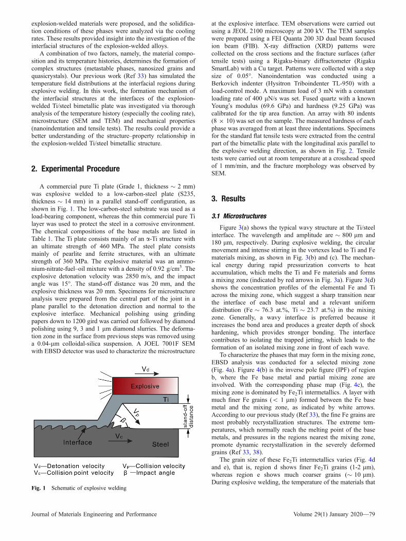
Figure 3(a) shows the typical wavy structure at the Ti/steelinterface. The wavelength and amplitude are � 800 lm and180 lm, respectively. During explosive welding, the circularmovement and intense stirring in the vortexes lead to Ti and Fematerials mixing, as shown in Fig. 3(b) and (c). The mechan-ical energy during rapid pressurization converts to heataccumulation, which melts the Ti and Fe materials and formsa mixing zone (indicated by red arrows in Fig. 3a). Figure 3(d)shows the concentration profiles of the elemental Fe and Tiacross the mixing zone, which suggest a sharp transition nearthe interface of each base metal and a relevant uniformdistribution (Fe � 76.3 at.%, Ti � 23.7 at.%) in the mixingzone. Generally, a wavy interface is preferred because itincreases the bond area and produces a greater depth of shockhardening, which provides stronger bonding. The interfacecontributes to isolating the trapped jetting, which leads to theformation of an isolated mixing zone in front of each wave.
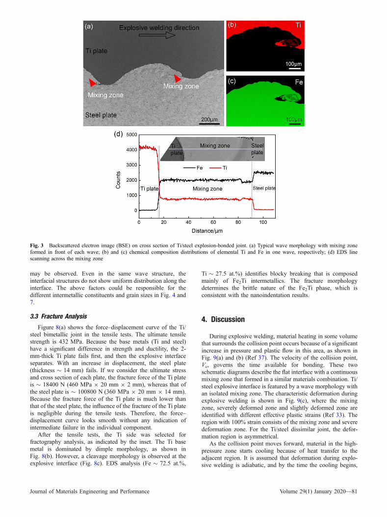
To characterize the phases that may form in the mixing zone,EBSD analysis was conducted for a selected mixing zone(Fig. 4a). Figure 4(b) is the inverse pole figure (IPF) of regionb, where the Fe base metal and partial mixing zone areinvolved. With the corresponding phase map (Fig. 4c), themixing zone is dominated by Fe2Ti intermetallics. A layer withmuch finer Fe grains (< 1 lm) formed between the Fe basemetal and the mixing zone, as indicated by white arrows.According to our previous study (Ref 33), the fine Fe grains aremost probably recrystallization structures. The extreme tem-peratures, which normally reach the melting point of the basemetals, and pressures in the regions nearest the mixing zone,promote dynamic recrystallization in the severely deformedgrains (Ref 33, 38).
The grain size of these Fe2Ti intermetallics varies (Fig. 4dand e), that is, region d shows finer Fe2Ti grains (1-2 lm),whereas region e shows much coarser grains (� 10 lm).During explosive welding, the temperature of the materials that
Fig. 1 Schematic of explosive welding
Journal of Materials Engineering and Performance Volume 29(1) January 2020—79

surround the collision point could reach the melting point.Region d close to the Fe and Ti base metals experiences ahigher cooling rate than region e (in the center of the mixingzone), which could suppress grain growth to some extent. TheFe2Ti grain size presented here is much coarser than thatobserved in our previous work (Ref 33) for the CP-Ti/Q345bimetallic plate. The cracks in this selected mixing zone implythe brittle nature of these Fe2Ti intermetallics.
To determine the microstructure distributions in the mixingzone, TEM lamella were prepared by FIB, shown in Fig. 5(a)and (b). Figure 5(c) and (d) presents the TEM bright-fieldcontrast images and corresponding diffraction patterns. FeTiintermetallics with a maximum grain size of � 200 nm aredistributed among the Fe2Ti matrix grains in Fig. 5(c). Somenanoscaled Fe2Ti grains (identified by TEM-EDS analysis) arevisible, as indicated by red arrows in Fig. 5(e). NanoscaledFeTi intermetallics are visible here, whereas they are notpresent in the EBSD phase map in 4c, most likely because ofthe lower-resolution EBSD method. Some researchers havereported amorphous phases that formed at the Ti/steel interface(Ref 39, 40). However, these phases are not observed here. Fe-Ti alloys do not have high glass-formation abilities. Even neareutectic compositions, Fe-Ti amorphous phases are rarelyobtained under rapid cooling experiments (Ref 41, 42). Minoradditions of alloying elements in titanium and steel couldenhance the glass-formation abilities and promote glass forma-tion (Ref 43). The alloy content in the base metals (low carbonsteel and commercial pure titanium in Table 1) is relatively low,which may be responsible for the absence of amorphous phasesin the mixing zone.
The XRD pattern on the Ti/steel cross sections confirms thepresence of Fe2Ti and FeTi intermetallic phases, as shown inFig. 6(a). After tensile tests, the Ti side and steel side are
separated. Figure 6(b) is obtained on the fracture surfaces (atthe Ti side) after the tensile tests, which also identifies similarphase constituents.
3.2 Nanoindentation
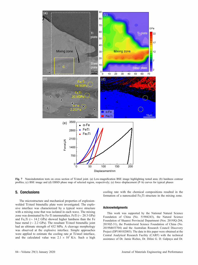
A grid with 80 points, as outlined by a dashed whiterectangle in Fig. 7(a), was subjected to nanoindentation tests.Figure 7(b) shows the corresponding hardness contour profiles.Most of the mixing zone presents a uniform hardness contour(9-13 GPa), whereas the region near the Fe base metal showshigher hardness (indicated by a red contour in Fig. 7b), from 17to 22 GPa. With the EDS analysis, this region consists mainlyof FeTi intermetallics (Fe � 57.2 at.%, Ti � 42.8 at.%),whereas the remaining region consists of Fe2Ti intermetallics(Fe � 23.3 at.%, Ti � 76.7 at.%). Figure 7(c) and (d) displaysrepresentative Berkovich impressions (marked by a yellowrectangle in Fig. 7a) and an EBSD phase map, respectively.FeTi and a-Fe have similar crystalline parameters, which makeit difficult to distinguish them under a EBSD detector.Therefore, only the crystal lattice of the a-Fe phase is inputfor EBSD analysis. The region with higher hardness is darkgray, whereas the other region is light gray. As shown inFig. 7(c), the FeTi (� 20.3 GPa) and Fe2Ti (� 14.2 GPa) havesmaller indents than the Fe base metal (� 2.2 GPa). The force–displacement (P–h) curves for these typical phases are plottedin Fig. 6(e). The maximal indenter displacement with a peakload of 3 mN is 81.7 and 97.8 nm in the FeTi and Fe2Ti phases,respectively.
In practice, particularly when large workpieces are joined,collision parameters may change during welding because of thegap variability or inhomogeneity of the explosives. Thus,within the same explosion-welded plate, different structures
Fig. 2 Illustration of tensile sample used to examine the mechanical properties of the Ti/steel bimetallic plate. (a) Location of fabricated tensilesample; (b) dimensions of tensile sample; (c) schematic of tensile tests
Table 1 Chemical compositions of applied materials (wt.%)
C Si Mn Ti Cu Fe V O N H
Ti (grade 1) 0.10 ... ... Bal. ... 0.25 ... 0.20 0.03 0.015Steel (S235) 0.12 0.30 0.50 ... ... Bal. ... ... ... ...
80—Volume 29(1) January 2020 Journal of Materials Engineering and Performance
may be observed. Even in the same wave structure, theinterfacial structures do not show uniform distribution along theinterface. The above factors could be responsible for thedifferent intermetallic constituents and grain sizes in Fig. 4 and7.
3.3 Fracture Analysis
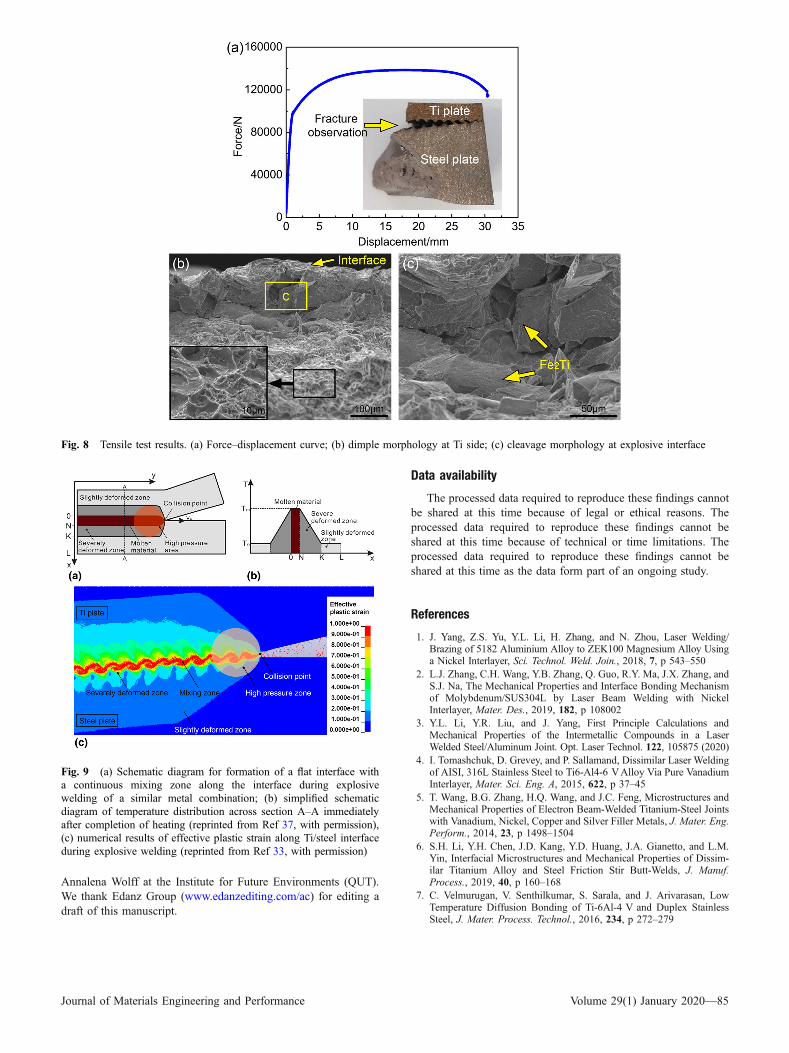
Figure 8(a) shows the force–displacement curve of the Ti/steel bimetallic joint in the tensile tests. The ultimate tensilestrength is 432 MPa. Because the base metals (Ti and steel)have a significant difference in strength and ductility, the 2-mm-thick Ti plate fails first, and then the explosive interfaceseparates. With an increase in displacement, the steel plate(thickness � 14 mm) fails. If we consider the ultimate stressand cross section of each plate, the fracture force of the Ti plateis � 18400 N (460 MPa 9 20 mm 9 2 mm), whereas that ofthe steel plate is � 100800 N (360 MPa 9 20 mm 9 14 mm).Because the fracture force of the Ti plate is much lower thanthat of the steel plate, the influence of the fracture of the Ti plateis negligible during the tensile tests. Therefore, the force–displacement curve looks smooth without any indication ofintermediate failure in the individual component.
After the tensile tests, the Ti side was selected forfractography analysis, as indicated by the inset. The Ti basemetal is dominated by dimple morphology, as shown inFig. 8(b). However, a cleavage morphology is observed at theexplosive interface (Fig. 8c). EDS analysis (Fe � 72.5 at.%,
Ti � 27.5 at.%) identifies blocky breaking that is composedmainly of Fe2Ti intermetallics. The fracture morphologydetermines the brittle nature of the Fe2Ti phase, which isconsistent with the nanoindentation results.
4. Discussion
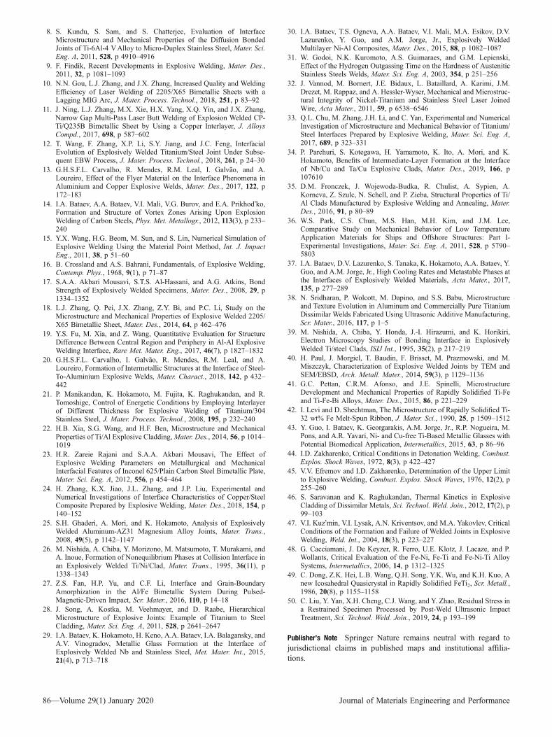
During explosive welding, material heating in some volumethat surrounds the collision point occurs because of a significantincrease in pressure and plastic flow in this area, as shown inFig. 9(a) and (b) (Ref 37). The velocity of the collision point,Vc, governs the time available for bonding. These twoschematic diagrams describe the flat interface with a continuousmixing zone that formed in a similar materials combination. Ti/steel explosive interface is featured by a wave morphology withan isolated mixing zone. The characteristic deformation duringexplosive welding is shown in Fig. 9(c), where the mixingzone, severely deformed zone and slightly deformed zone areidentified with different effective plastic strains (Ref 33). Theregion with 100% strain consists of the mixing zone and severedeformation zone. For the Ti/steel dissimilar joint, the defor-mation region is asymmetrical.
As the collision point moves forward, material in the high-pressure zone starts cooling because of heat transfer to theadjacent region. It is assumed that deformation during explo-sive welding is adiabatic, and by the time the cooling begins,
Fig. 3 Backscattered electron image (BSE) on cross section of Ti/steel explosion-bonded joint. (a) Typical wave morphology with mixing zoneformed in front of each wave; (b) and (c) chemical composition distributions of elemental Ti and Fe in one wave, respectively; (d) EDS linescanning across the mixing zone
Journal of Materials Engineering and Performance Volume 29(1) January 2020—81
the deformation process has ended. In (Ref 44, 45), thesolidification time (ts) of the molten metal must be lower thanthe time needed for a positive pressure (tp) at the interface. Theexpressions that are proposed to estimate tp and ts are obtainedfrom (Ref 44, 45):
tp ¼ 0:5þ0:66qfly � V 2
c
Gfly
� �� �� dflyVc
ts ¼Q2
4p � cfly � kfly � qfly � T2mfly
ðEq 1Þ
Q ¼ 6:8 � 10�2 � V 2c � qfly � dfly �
dbasedfly þ dbase
� sin2 b2
� �ðEq 2Þ
where, qfly, Gfly, Vc, dfly, cfly, kfly and Tmfly are the density, shearmodulus, collision point velocity, thickness, specific heat,thermal conductivity and melting point of the fly plate,respectively; Q is the heat released at the interface; dbase isthe thickness of the base plate and b is the collision angle.
qfly is 4.5 kg/m3, Gfly is 55 GPa, Vc is 2850 m/s, dfly is2 mm, dbase is 14 mm, kfly is 15 Wm�1 k�1, cfly is523 J kg�1 K�1, Tmfly is 1670 �C and b is 15�.
The calculated tp and ts for the Ti/steel joint are 0.81 and0.09 ls, respectively. The above criterion is reliable for jointsthat are welded by ammonium-nitrate-fuel–oil explosion. Theabove expressions are developed for similar materials welding,where the formation of intermetallic phases usually does notoccur. Because intermetallics are formed at the Ti/steelinterface, one may suggest a consideration of the physicalproperties of these phases to obtain a more accurate solidifi-cation time. However, information on the physical properties ofthese intermetallics (FeTi and Fe2Ti) is limited. Furthermore,the mixing zone is not fully homogeneous. Therefore, anaccurate analysis of the solidification time when considering theintermetallics in the mixing zone cannot be made. Results inRef 46, 47 suggest that these two equations are suitable fordissimilar materials welding when the interfacial mixing zone isthin. If the interfacial mixing zone is thick, Eq 2 will be invalid.In this study, the Fe-Ti intermetallics that formed at the Ti/steelinterface are isolated (mixing zone in Fig. 3). The ts (90 ns) thatis calculated here is similar to that reported in Ref 19, whichproves the applicability of Eq 2 in a Ti/steel dissimilar joint.Therefore, Eq 2 can be adapted to estimate the solidificationtime (ts). These two expressions indicate that an increase in fly-
Fig. 4 EBSD results of mixing zone. (a) BSE image that indicates regions selected for EBSD analysis; (b), (d) and (e) EBSD IPFs in region b,d and e, respectively; (c) EBSD phase map in region b
82—Volume 29(1) January 2020 Journal of Materials Engineering and Performance
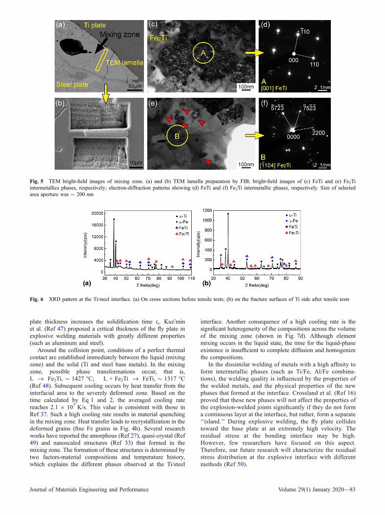
plate thickness increases the solidification time ts. Kuz�minet al. (Ref 47) proposed a critical thickness of the fly plate inexplosive welding materials with greatly different properties(such as aluminum and steel).
Around the collision point, conditions of a perfect thermalcontact are established immediately between the liquid (mixingzone) and the solid (Ti and steel base metals). In the mixingzone, possible phase transformations occur, that is,L fi Fe2Ti, � 1427 �C; L + Fe2Ti fi FeTi, � 1317 �C(Ref 48). Subsequent cooling occurs by heat transfer from theinterfacial area to the severely deformed zone. Based on thetime calculated by Eq 1 and 2, the averaged cooling ratereaches 2.1 9 107 K/s. This value is consistent with those inRef 37. Such a high cooling rate results in material quenchingin the mixing zone. Heat transfer leads to recrystallization in thedeformed grains (fine Fe grains in Fig. 4b). Several researchworks have reported the amorphous (Ref 27), quasi-crystal (Ref49) and nanoscaled structures (Ref 33) that formed in themixing zone. The formation of these structures is determined bytwo factors-material compositions and temperature history,which explains the different phases observed at the Ti/steel
interface. Another consequence of a high cooling rate is thesignificant heterogeneity of the compositions across the volumeof the mixing zone (shown in Fig. 7d). Although elementmixing occurs in the liquid state, the time for the liquid-phaseexistence is insufficient to complete diffusion and homogenizethe compositions.
In the dissimilar welding of metals with a high affinity toform intermetallic phases (such as Ti/Fe, Al/Fe combina-tions), the welding quality is influenced by the properties ofthe welded metals, and the physical properties of the newphases that formed at the interface. Crossland et al. (Ref 16)proved that these new phases will not affect the properties ofthe explosion-welded joints significantly if they do not forma continuous layer at the interface, but rather, form a separate‘‘island.’’ During explosive welding, the fly plate collidestoward the base plate at an extremely high velocity. Theresidual stress at the bonding interface may be high.However, few researchers have focused on this aspect.Therefore, our future research will characterize the residualstress distribution at the explosive interface with differentmethods (Ref 50).
Fig. 5 TEM bright-field images of mixing zone. (a) and (b) TEM lamella preparation by FIB; bright-field images of (c) FeTi and (e) Fe2Tiintermetallics phases, respectively; electron-diffraction patterns showing (d) FeTi and (f) Fe2Ti intermetallic phases, respectively. Size of selectedarea aperture was � 200 nm
Fig. 6 XRD pattern at the Ti/steel interface. (a) On cross sections before tensile tests; (b) on the fracture surfaces of Ti side after tensile tests
Journal of Materials Engineering and Performance Volume 29(1) January 2020—83
5. Conclusions
The microstructure and mechanical properties of explosion-welded Ti/steel bimetallic plate were investigated. The explo-sive interface was characterized by a typical wave structurewith a mixing zone that was isolated in each wave. The mixingzone was dominated by Fe-Ti intermetallics. FeTi (� 20.3 GPa)and Fe2Ti (� 14.2 GPa) showed higher hardness than the Febase metal (� 2.2 GPa). The resultant Ti/steel bimetallic jointhad an ultimate strength of 432 MPa. A cleavage morphologywas observed at the explosive interface. Simple approacheswere applied to estimate the cooling rate at Ti/steel interface,and the calculated value was 2.1 9 107 K/s. Such a high
cooling rate with the chemical compositions resulted in theformation of a nanoscaled Fe2Ti structure in the mixing zone.
Acknowledgments
This work was supported by the National Natural ScienceFoundation of China (No. 51904243), the Natural ScienceFoundation of Shaanxi Provincial Department (Nos. 2019JQ-284,2019JZ-31), the Postdoctoral Science Foundation of China (No.2019M653704) and the Australian Research Council DiscoveryProject (DP180102003). The data in this paper were obtained at theCentral Analytical Research Facility (CARF) with the technicalassistance of Dr. Jamie Riches, Dr. Dilini G. D. Galpaya and Dr.
Fig. 7 Nanoindentation tests on cross section of Ti/steel joint. (a) Low-magnification BSE image highlighting tested area; (b) hardness contourprofiles; (c) BSE image and (d) EBSD phase map of selected region, respectively; (e) force–displacement (P–h) curves for typical phases
84—Volume 29(1) January 2020 Journal of Materials Engineering and Performance
Annalena Wolff at the Institute for Future Environments (QUT).We thank Edanz Group (www.edanzediting.com/ac) for editing adraft of this manuscript.
Data availability
The processed data required to reproduce these findings cannotbe shared at this time because of legal or ethical reasons. Theprocessed data required to reproduce these findings cannot beshared at this time because of technical or time limitations. Theprocessed data required to reproduce these findings cannot beshared at this time as the data form part of an ongoing study.
References
1. J. Yang, Z.S. Yu, Y.L. Li, H. Zhang, and N. Zhou, Laser Welding/Brazing of 5182 Aluminium Alloy to ZEK100 Magnesium Alloy Usinga Nickel Interlayer, Sci. Technol. Weld. Join., 2018, 7, p 543–550
2. L.J. Zhang, C.H. Wang, Y.B. Zhang, Q. Guo, R.Y. Ma, J.X. Zhang, andS.J. Na, The Mechanical Properties and Interface Bonding Mechanismof Molybdenum/SUS304L by Laser Beam Welding with NickelInterlayer, Mater. Des., 2019, 182, p 108002
3. Y.L. Li, Y.R. Liu, and J. Yang, First Principle Calculations andMechanical Properties of the Intermetallic Compounds in a LaserWelded Steel/Aluminum Joint. Opt. Laser Technol. 122, 105875 (2020)
4. I. Tomashchuk, D. Grevey, and P. Sallamand, Dissimilar Laser Weldingof AISI, 316L Stainless Steel to Ti6-Al4-6 VAlloy Via Pure VanadiumInterlayer, Mater. Sci. Eng. A, 2015, 622, p 37–45
5. T. Wang, B.G. Zhang, H.Q. Wang, and J.C. Feng, Microstructures andMechanical Properties of Electron Beam-Welded Titanium-Steel Jointswith Vanadium, Nickel, Copper and Silver Filler Metals, J. Mater. Eng.Perform., 2014, 23, p 1498–1504
6. S.H. Li, Y.H. Chen, J.D. Kang, Y.D. Huang, J.A. Gianetto, and L.M.Yin, Interfacial Microstructures and Mechanical Properties of Dissim-ilar Titanium Alloy and Steel Friction Stir Butt-Welds, J. Manuf.Process., 2019, 40, p 160–168
7. C. Velmurugan, V. Senthilkumar, S. Sarala, and J. Arivarasan, LowTemperature Diffusion Bonding of Ti-6Al-4 V and Duplex StainlessSteel, J. Mater. Process. Technol., 2016, 234, p 272–279
Fig. 8 Tensile test results. (a) Force–displacement curve; (b) dimple morphology at Ti side; (c) cleavage morphology at explosive interface
Fig. 9 (a) Schematic diagram for formation of a flat interface witha continuous mixing zone along the interface during explosivewelding of a similar metal combination; (b) simplified schematicdiagram of temperature distribution across section A–A immediatelyafter completion of heating (reprinted from Ref 37, with permission),(c) numerical results of effective plastic strain along Ti/steel interfaceduring explosive welding (reprinted from Ref 33, with permission)
Journal of Materials Engineering and Performance Volume 29(1) January 2020—85
8. S. Kundu, S. Sam, and S. Chatterjee, Evaluation of InterfaceMicrostructure and Mechanical Properties of the Diffusion BondedJoints of Ti-6Al-4 VAlloy to Micro-Duplex Stainless Steel, Mater. Sci.Eng. A, 2011, 528, p 4910–4916
9. F. Findik, Recent Developments in Explosive Welding, Mater. Des.,2011, 32, p 1081–1093
10. N.N. Gou, L.J. Zhang, and J.X. Zhang, Increased Quality and WeldingEfficiency of Laser Welding of 2205/X65 Bimetallic Sheets with aLagging MIG Arc, J. Mater. Process. Technol., 2018, 251, p 83–92
11. J. Ning, L.J. Zhang, M.X. Xie, H.X. Yang, X.Q. Yin, and J.X. Zhang,Narrow Gap Multi-Pass Laser Butt Welding of Explosion Welded CP-Ti/Q235B Bimetallic Sheet by Using a Copper Interlayer, J. AlloysCompd., 2017, 698, p 587–602
12. T. Wang, F. Zhang, X.P. Li, S.Y. Jiang, and J.C. Feng, InterfacialEvolution of Explosively Welded Titanium/Steel Joint Under Subse-quent EBW Process, J. Mater. Process. Technol., 2018, 261, p 24–30
13. G.H.S.F.L. Carvalho, R. Mendes, R.M. Leal, I. Galvao, and A.Loureiro, Effect of the Flyer Material on the Interface Phenomena inAluminium and Copper Explosive Welds, Mater. Des., 2017, 122, p172–183
14. I.A. Bataev, A.A. Bataev, V.I. Mali, V.G. Burov, and E.A. Prikhod�ko,Formation and Structure of Vortex Zones Arising Upon ExplosionWelding of Carbon Steels, Phys. Met. Metallogr., 2012, 113(3), p 233–240
15. Y.X. Wang, H.G. Beom, M. Sun, and S. Lin, Numerical Simulation ofExplosive Welding Using the Material Point Method, Int. J. ImpactEng., 2011, 38, p 51–60
16. B. Crossland and A.S. Bahrani, Fundamentals, of Explosive Welding,Contemp. Phys., 1968, 9(1), p 71–87
17. S.A.A. Akbari Mousavi, S.T.S. Al-Hassani, and A.G. Atkins, BondStrength of Explosively Welded Specimens, Mater. Des., 2008, 29, p1334–1352
18. L.J. Zhang, Q. Pei, J.X. Zhang, Z.Y. Bi, and P.C. Li, Study on theMicrostructure and Mechanical Properties of Explosive Welded 2205/X65 Bimetallic Sheet, Mater. Des., 2014, 64, p 462–476
19. Y.S. Fu, M. Xia, and Z. Wang, Quantitative Evaluation for StructureDifference Between Central Region and Periphery in Al-Al ExplosiveWelding Interface, Rare Met. Mater. Eng., 2017, 46(7), p 1827–1832
20. G.H.S.F.L. Carvalho, I. Galvao, R. Mendes, R.M. Leal, and A.Loureiro, Formation of Intermetallic Structures at the Interface of Steel-To-Aluminium Explosive Welds, Mater. Charact., 2018, 142, p 432–442
21. P. Manikandan, K. Hokamoto, M. Fujita, K. Raghukandan, and R.Tomoshige, Control of Energetic Conditions by Employing Interlayerof Different Thickness for Explosive Welding of Titanium/304Stainless Steel, J. Mater. Process. Technol., 2008, 195, p 232–240
22. H.B. Xia, S.G. Wang, and H.F. Ben, Microstructure and MechanicalProperties of Ti/Al Explosive Cladding,Mater. Des., 2014, 56, p 1014–1019
23. H.R. Zareie Rajani and S.A.A. Akbari Mousavi, The Effect ofExplosive Welding Parameters on Metallurgical and MechanicalInterfacial Features of Inconel 625/Plain Carbon Steel Bimetallic Plate,Mater. Sci. Eng. A, 2012, 556, p 454–464
24. H. Zhang, K.X. Jiao, J.L. Zhang, and J.P. Liu, Experimental andNumerical Investigations of Interface Characteristics of Copper/SteelComposite Prepared by Explosive Welding, Mater. Des., 2018, 154, p140–152
25. S.H. Ghaderi, A. Mori, and K. Hokamoto, Analysis of ExplosivelyWelded Aluminum-AZ31 Magnesium Alloy Joints, Mater. Trans.,2008, 49(5), p 1142–1147
26. M. Nishida, A. Chiba, Y. Morizono, M. Matsumoto, T. Murakami, andA. Inoue, Formation of Nonequilibrium Phases at Collision Interface inan Explosively Welded Ti/Ni/Clad, Mater. Trans., 1995, 36(11), p1338–1343
27. Z.S. Fan, H.P. Yu, and C.F. Li, Interface and Grain-BoundaryAmorphization in the Al/Fe Bimetallic System During Pulsed-Magnetic-Driven Impact, Scr. Mater., 2016, 110, p 14–18
28. J. Song, A. Kostka, M. Veehmayer, and D. Raabe, HierarchicalMicrostructure of Explosive Joints: Example of Titanium to SteelCladding, Mater. Sci. Eng. A, 2011, 528, p 2641–2647
29. I.A. Bataev, K. Hokamoto, H. Keno, A.A. Bataev, I.A. Balagansky, andA.V. Vinogradov, Metallic Glass Formation at the Interface ofExplosively Welded Nb and Stainless Steel, Met. Mater. Int., 2015,21(4), p 713–718
30. I.A. Bataev, T.S. Ogneva, A.A. Bataev, V.I. Mali, M.A. Esikov, D.V.Lazurenko, Y. Guo, and A.M. Jorge, Jr., Explosively WeldedMultilayer Ni-Al Composites, Mater. Des., 2015, 88, p 1082–1087
31. W. Godoi, N.K. Kuromoto, A.S. Guimaraes, and G.M. Lepienski,Effect of the Hydrogen Outgassing Time on the Hardness of AusteniticStainless Steels Welds, Mater. Sci. Eng. A, 2003, 354, p 251–256
32. J. Vannod, M. Bornert, J.E. Bidaux, L. Bataillard, A. Karimi, J.M.Drezet, M. Rappaz, and A. Hessler-Wyser, Mechanical and Microstruc-tural Integrity of Nickel-Titanium and Stainless Steel Laser JoinedWire, Acta Mater., 2011, 59, p 6538–6546
33. Q.L. Chu, M. Zhang, J.H. Li, and C. Yan, Experimental and NumericalInvestigation of Microstructure and Mechanical Behavior of Titanium/Steel Interfaces Prepared by Explosive Welding, Mater. Sci. Eng. A,2017, 689, p 323–331
34. P. Parchuri, S. Kotegawa, H. Yamamoto, K. Ito, A. Mori, and K.Hokamoto, Benefits of Intermediate-Layer Formation at the Interfaceof Nb/Cu and Ta/Cu Explosive Clads, Mater. Des., 2019, 166, p107610
35. D.M. Fronczek, J. Wojewoda-Budka, R. Chulist, A. Sypien, A.Korneva, Z. Szulc, N. Schell, and P. Zieba, Structural Properties of Ti/Al Clads Manufactured by Explosive Welding and Annealing, Mater.Des., 2016, 91, p 80–89
36. W.S. Park, C.S. Chun, M.S. Han, M.H. Kim, and J.M. Lee,Comparative Study on Mechanical Behavior of Low TemperatureApplication Materials for Ships and Offshore Structures: Part I-Experimental Investigations, Mater. Sci. Eng. A, 2011, 528, p 5790–5803
37. I.A. Bataev, D.V. Lazurenko, S. Tanaka, K. Hokamoto, A.A. Bataev, Y.Guo, and A.M. Jorge, Jr., High Cooling Rates and Metastable Phases atthe Interfaces of Explosively Welded Materials, Acta Mater., 2017,135, p 277–289
38. N. Sridharan, P. Wolcott, M. Dapino, and S.S. Babu, Microstructureand Texture Evolution in Aluminum and Commercially Pure TitaniumDissimilar Welds Fabricated Using Ultrasonic Additive Manufacturing,Scr. Mater., 2016, 117, p 1–5
39. M. Nishida, A. Chiba, Y. Honda, J.-I. Hirazumi, and K. Horikiri,Electron Microscopy Studies of Bonding Interface in ExplosivelyWelded Ti/steel Clads, ISIJ Int., 1995, 35(2), p 217–219
40. H. Paul, J. Morgiel, T. Baudin, F. Brisset, M. Prazmowski, and M.Miszczyk, Characterization of Explosive Welded Joints by TEM andSEM/EBSD, Arch. Metall. Mater., 2014, 59(3), p 1129–1136
41. G.C. Pettan, C.R.M. Afonso, and J.E. Spinelli, MicrostructureDevelopment and Mechanical Properties of Rapidly Solidified Ti-Feand Ti-Fe-Bi Alloys, Mater. Des., 2015, 86, p 221–229
42. I. Levi and D. Shechtman, The Microstructure of Rapidly Solidified Ti-32 wt% Fe Melt-Spun Ribbon, J. Mater. Sci., 1990, 25, p 1509–1512
43. Y. Guo, I. Bataev, K. Georgarakis, A.M. Jorge, Jr., R.P. Nogueira, M.Pons, and A.R. Yavari, Ni- and Cu-free Ti-Based Metallic Glasses withPotential Biomedical Application, Intermetallics, 2015, 63, p 86–96
44. I.D. Zakharenko, Critical Conditions in Detonation Welding, Combust.Explos. Shock Waves, 1972, 8(3), p 422–427
45. V.V. Efremov and I.D. Zakharenko, Determination of the Upper Limitto Explosive Welding, Combust. Explos. Shock Waves, 1976, 12(2), p255–260
46. S. Saravanan and K. Raghukandan, Thermal Kinetics in ExplosiveCladding of Dissimilar Metals, Sci. Technol. Weld. Join., 2012, 17(2), p99–103
47. V.I. Kuz�min, V.I. Lysak, A.N. Kriventsov, and M.A. Yakovlev, CriticalConditions of the Formation and Failure of Welded Joints in ExplosiveWelding, Weld. Int., 2004, 18(3), p 223–227
48. G. Cacciamani, J. De Keyzer, R. Ferro, U.E. Klotz, J. Lacaze, and P.Wollants, Critical Evaluation of the Fe-Ni, Fe-Ti and Fe-Ni-Ti AlloySystems, Intermetallics, 2006, 14, p 1312–1325
49. C. Dong, Z.K. Hei, L.B. Wang, Q.H. Song, Y.K. Wu, and K.H. Kuo, Anew Icosahedral Quasicrystal in Rapidly Solidified FeTi2, Scr. Metall.,1986, 20(8), p 1155–1158
50. C. Liu, Y. Yan, X.H. Cheng, C.J. Wang, and Y. Zhao, Residual Stress ina Restrained Specimen Processed by Post-Weld Ultrasonic ImpactTreatment, Sci. Technol. Weld. Join., 2019, 24, p 193–199
Publisher’s Note Springer Nature remains neutral with regard tojurisdictional claims in published maps and institutional affilia-tions.
86—Volume 29(1) January 2020 Journal of Materials Engineering and Performance


![1 Interfacial Rheology System. 2 Background of Interfacial Rheology Interfacial Shear Stress Interfacial Shear Viscosity = [ ]](https://static.fdocuments.net/doc/165x107/56649d1f5503460f949f3d29/1-interfacial-rheology-system-2-background-of-interfacial-rheology-interfacial.jpg)