INTERCOOLER UPGRADE INSTALLATION...
18
865 Jarvis Drive Morgan Hill, CA 95037 Tel: (408) 779-8584 Fax: (408) 779-8674 INTERCOOLER UPGRADE INSTALLATION INSTRUCTIONS PART NUMBER D330-0026 APPLICATION: 2016-17 F87 M2 Congratulations for being selective enough to use a Dinan Intercooler Upgrade Kit. We have spent many hours developing this kit to assure that you will receive maximum performance and durability with minimum difficulty in installation. Please take the time to read these instructions and call us if you have any difficulties during the installation. Familiarity with BMW recommended procedures is required to install this kit. These documents are available at http://www.bmwtechinfo.com/ DO NOT WORK ON VEHICLES SUPPORTED BY A JACK ONLY. USE SECURE JACK STANDS! ________________________________________________________________ PARTS LIST Qty Part # Description 1 D333-0026 Intercooler Assembly 1 D332-0074 Diffuser; Undercar 1 D333-0028 Hardware Kit ________________________________________________________________ REMOVE THE STOCK INTERCOOLER: 1. Remove the front bumper per BMW recommended procedure. 2. With the bumper removed, remove the lower cross piece. Remove this lower support and set it aside. This will be reinstalled.
Transcript of INTERCOOLER UPGRADE INSTALLATION...
865 Jarvis Drive Morgan Hill, CA 95037 Tel: (408) 779-8584 Fax: (408) 779-8674
INTERCOOLER UPGRADE
INSTALLATION INSTRUCTIONS
PART NUMBER D330-0026
APPLICATION: 2016-17 F87 M2
Congratulations for being selective enough to use a Dinan Intercooler Upgrade Kit. We
have spent many hours developing this kit to assure that you will receive maximum
performance and durability with minimum difficulty in installation. Please take the time
to read these instructions and call us if you have any difficulties during the installation.
Familiarity with BMW recommended procedures is required to install this kit. These
documents are available at http://www.bmwtechinfo.com/
DO NOT WORK ON VEHICLES SUPPORTED BY A JACK ONLY. USE SECURE
JACK STANDS!
________________________________________________________________
PARTS LIST
Qty Part # Description
1 D333-0026 Intercooler Assembly
1 D332-0074 Diffuser; Undercar
1 D333-0028 Hardware Kit
________________________________________________________________
REMOVE THE STOCK INTERCOOLER:
1. Remove the front bumper per BMW recommended procedure.
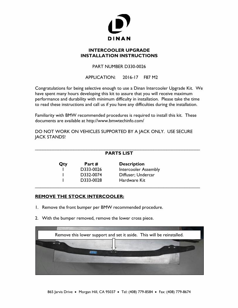
2. With the bumper removed, remove the lower cross piece.
Remove this lower support and set it aside. This will be reinstalled.
INS330-0026 Page 2 of 18 Rev. 12/19/16
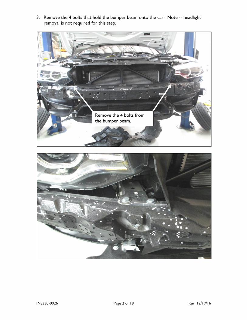
3. Remove the 4 bolts that hold the bumper beam onto the car. Note -- headlight
removal is not required for this step.
Remove the 4 bolts from
the bumper beam.
INS330-0026 Page 3 of 18 Rev. 12/19/16
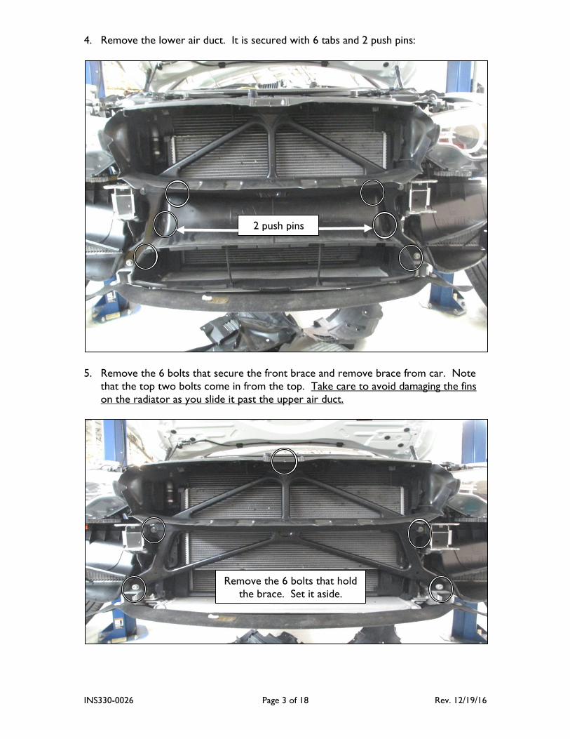
4. Remove the lower air duct. It is secured with 6 tabs and 2 push pins:
5. Remove the 6 bolts that secure the front brace and remove brace from car. Note
that the top two bolts come in from the top. Take care to avoid damaging the fins
on the radiator as you slide it past the upper air duct.
2 push pins
Remove the 6 bolts that hold
the brace. Set it aside.
INS330-0026 Page 4 of 18 Rev. 12/19/16
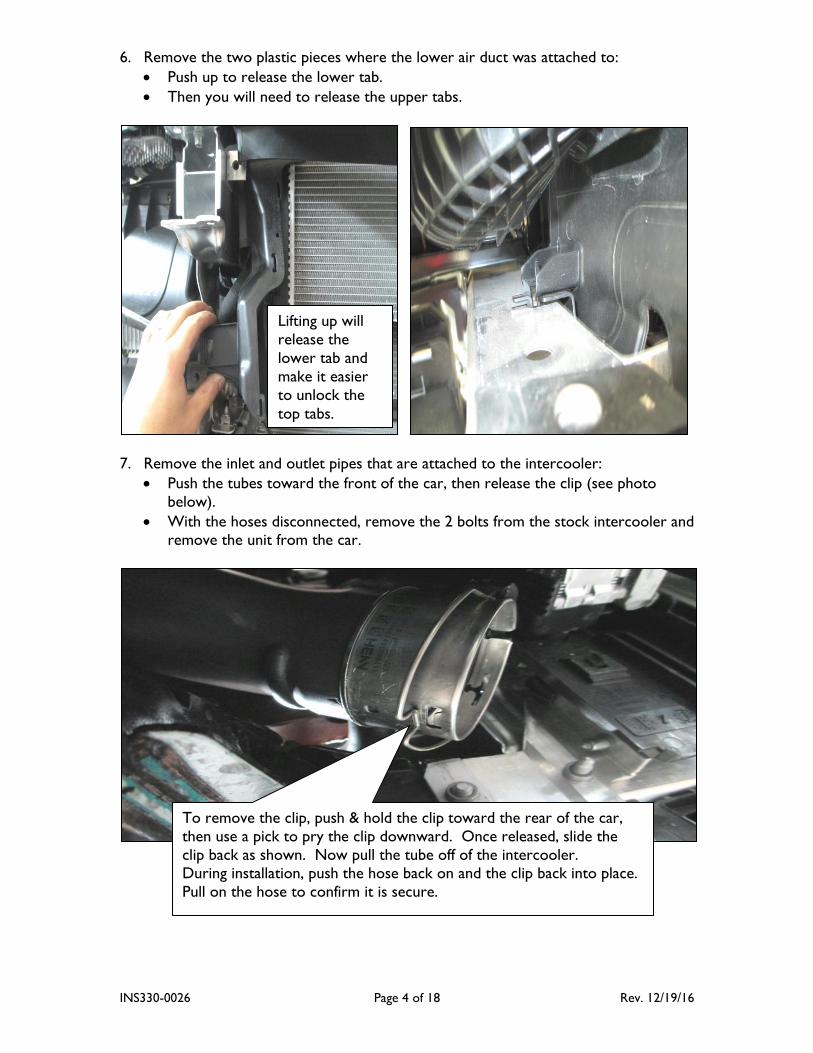
6. Remove the two plastic pieces where the lower air duct was attached to:
Push up to release the lower tab.
Then you will need to release the upper tabs.
7. Remove the inlet and outlet pipes that are attached to the intercooler:
Push the tubes toward the front of the car, then release the clip (see photo
below).
With the hoses disconnected, remove the 2 bolts from the stock intercooler and remove the unit from the car.
Lifting up will
release the
lower tab and
make it easier
to unlock the
top tabs.
To remove the clip, push & hold the clip toward the rear of the car,
then use a pick to pry the clip downward. Once released, slide the
clip back as shown. Now pull the tube off of the intercooler. During installation, push the hose back on and the clip back into place.
Pull on the hose to confirm it is secure.
INS330-0026 Page 5 of 18 Rev. 12/19/16
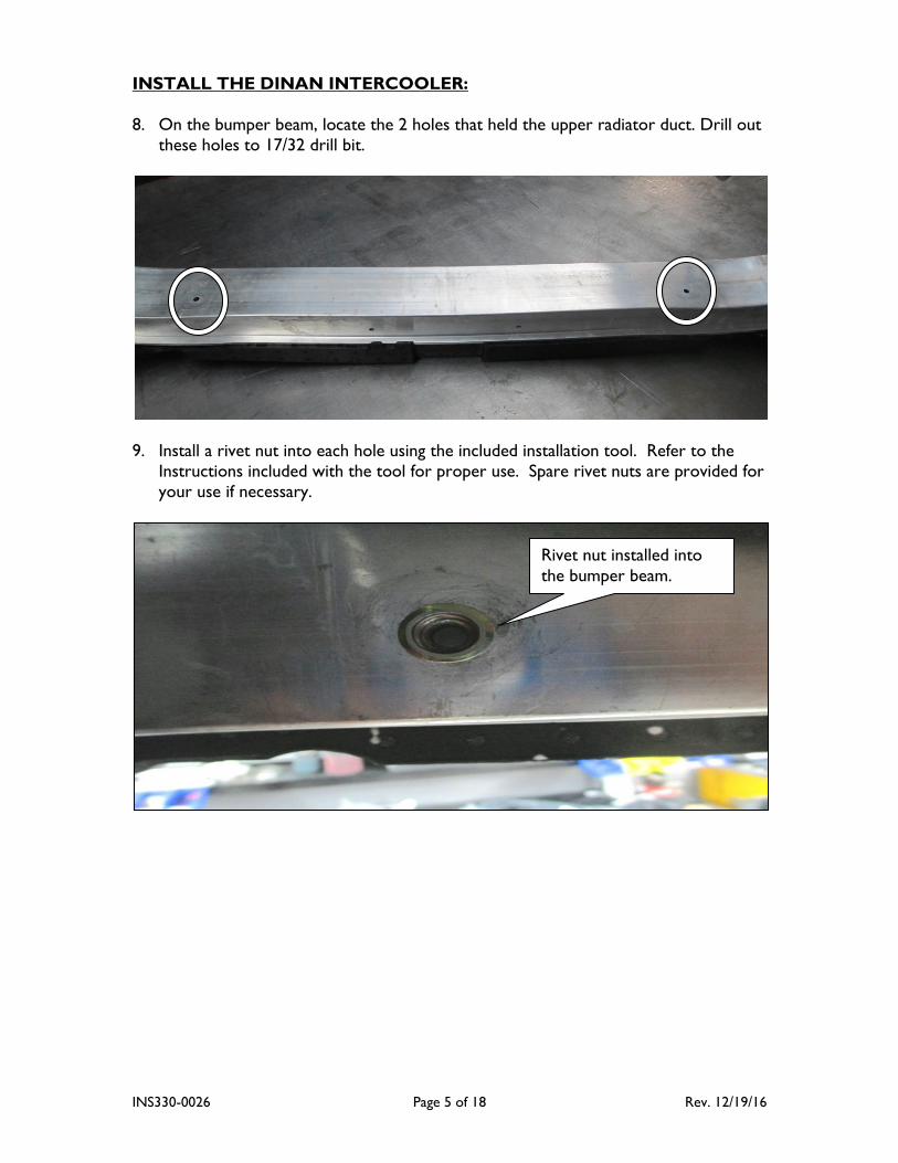
INSTALL THE DINAN INTERCOOLER:
8. On the bumper beam, locate the 2 holes that held the upper radiator duct. Drill out
these holes to 17/32 drill bit.
9. Install a rivet nut into each hole using the included installation tool. Refer to the
Instructions included with the tool for proper use. Spare rivet nuts are provided for
your use if necessary.
Rivet nut installed into
the bumper beam.
INS330-0026 Page 6 of 18 Rev. 12/19/16
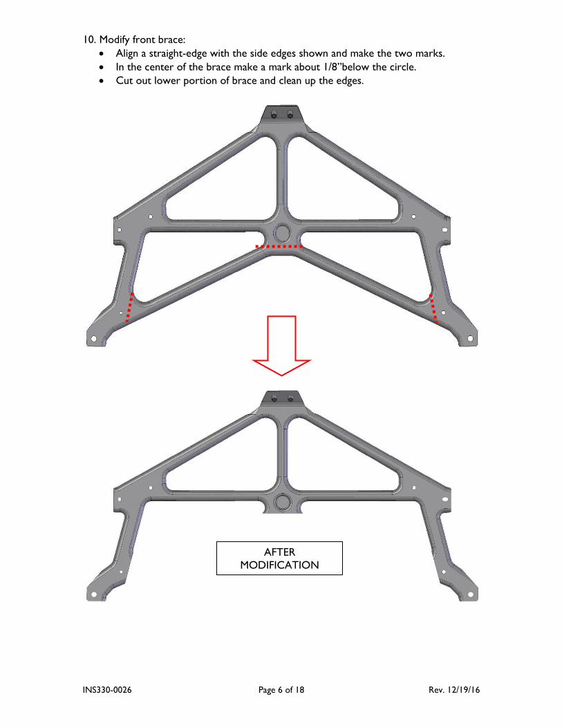
10. Modify front brace:
Align a straight-edge with the side edges shown and make the two marks.
In the center of the brace make a mark about 1/8”below the circle.
Cut out lower portion of brace and clean up the edges.
AFTER
MODIFICATION
INS330-0026 Page 7 of 18 Rev. 12/19/16
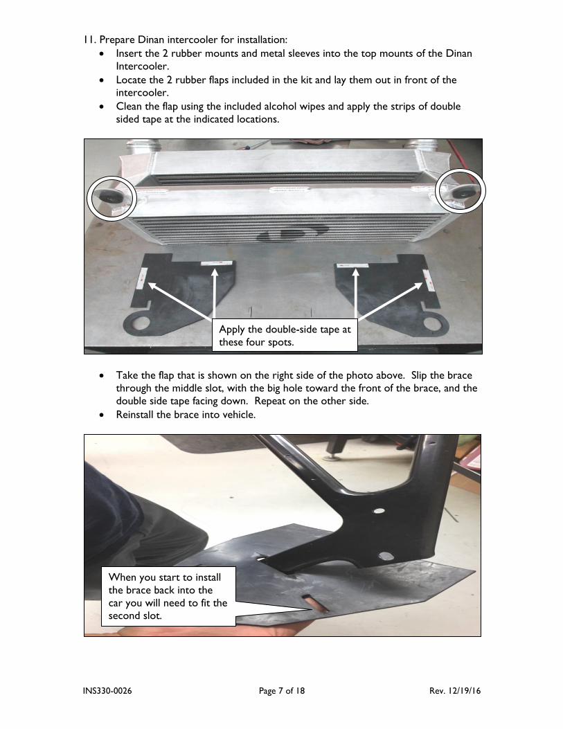
11. Prepare Dinan intercooler for installation:
Insert the 2 rubber mounts and metal sleeves into the top mounts of the Dinan
Intercooler.
Locate the 2 rubber flaps included in the kit and lay them out in front of the intercooler.
Clean the flap using the included alcohol wipes and apply the strips of double
sided tape at the indicated locations.
Take the flap that is shown on the right side of the photo above. Slip the brace
through the middle slot, with the big hole toward the front of the brace, and the
double side tape facing down. Repeat on the other side.
Reinstall the brace into vehicle.
Apply the double-side tape at
these four spots.
When you start to install
the brace back into the
car you will need to fit the second slot.
INS330-0026 Page 8 of 18 Rev. 12/19/16
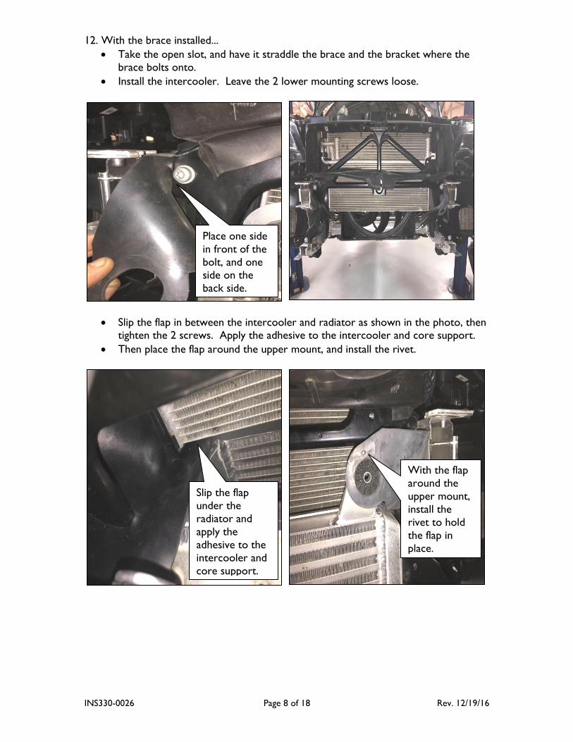
12. With the brace installed...
Take the open slot, and have it straddle the brace and the bracket where the
brace bolts onto.
Install the intercooler. Leave the 2 lower mounting screws loose.
Slip the flap in between the intercooler and radiator as shown in the photo, then tighten the 2 screws. Apply the adhesive to the intercooler and core support.
Then place the flap around the upper mount, and install the rivet.
Place one side
in front of the
bolt, and one side on the
back side.
Slip the flap
under the
radiator and
apply the
adhesive to the
intercooler and
core support.
With the flap
around the
upper mount,
install the
rivet to hold
the flap in
place.
INS330-0026 Page 9 of 18 Rev. 12/19/16
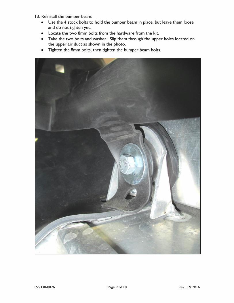
13. Reinstall the bumper beam:
Use the 4 stock bolts to hold the bumper beam in place, but leave them loose
and do not tighten yet.
Locate the two 8mm bolts from the hardware from the kit.
Take the two bolts and washer. Slip them through the upper holes located on
the upper air duct as shown in the photo.
Tighten the 8mm bolts, then tighten the bumper beam bolts.
INS330-0026 Page 10 of 18 Rev. 12/19/16
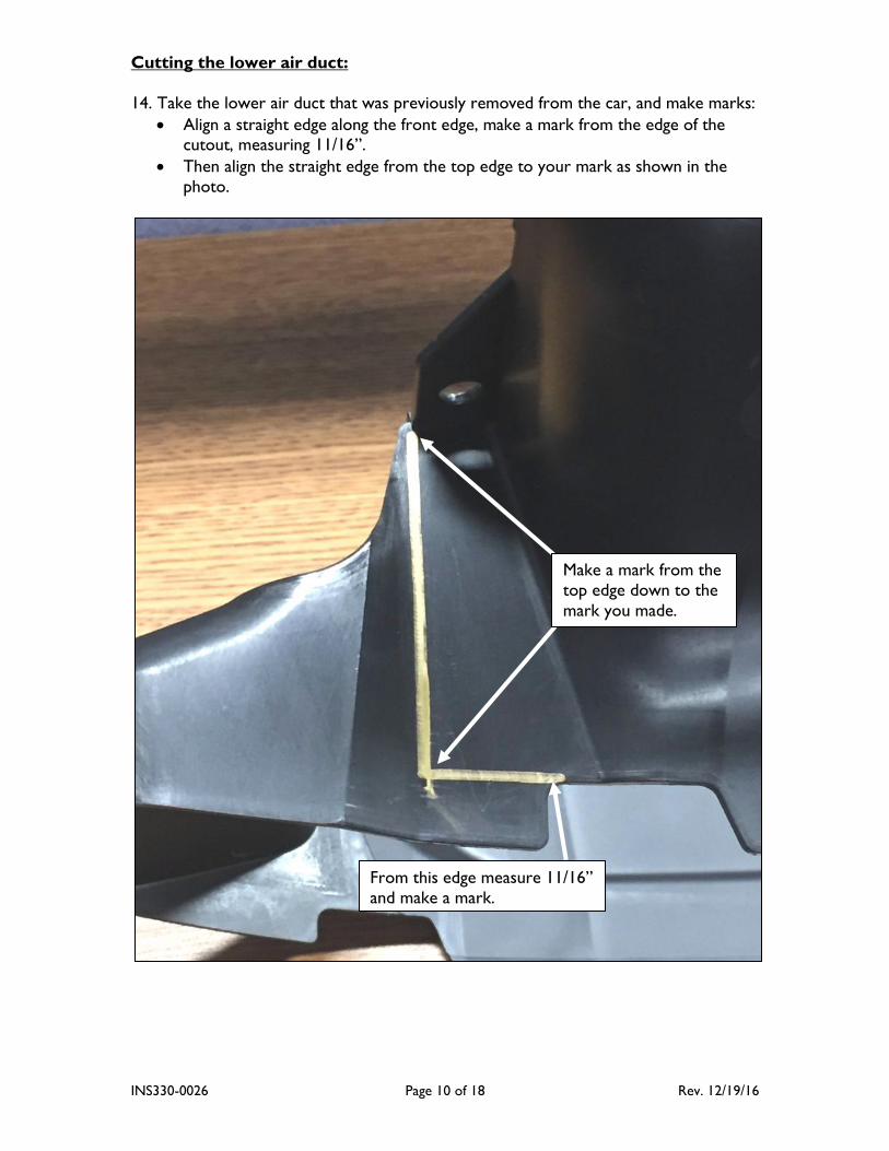
Cutting the lower air duct:
14. Take the lower air duct that was previously removed from the car, and make marks:
Align a straight edge along the front edge, make a mark from the edge of the cutout, measuring 11/16”.
Then align the straight edge from the top edge to your mark as shown in the
photo.
From this edge measure 11/16”
and make a mark.
Make a mark from the
top edge down to the
mark you made.
INS330-0026 Page 11 of 18 Rev. 12/19/16
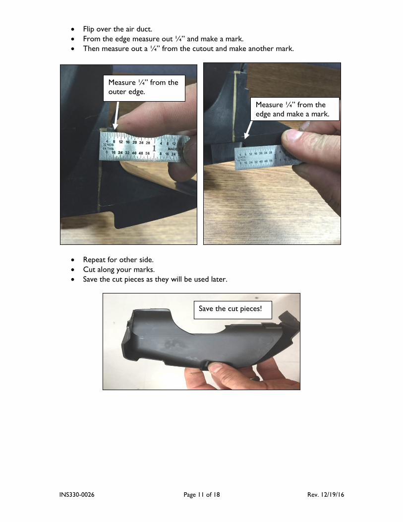
Flip over the air duct.
From the edge measure out ¼” and make a mark.
Then measure out a ¼” from the cutout and make another mark.
Repeat for other side.
Cut along your marks.
Save the cut pieces as they will be used later.
Measure ¼” from the
edge and make a mark.
Measure ¼” from the
outer edge.
Save the cut pieces!
INS330-0026 Page 12 of 18 Rev. 12/19/16
Trimming the grill:
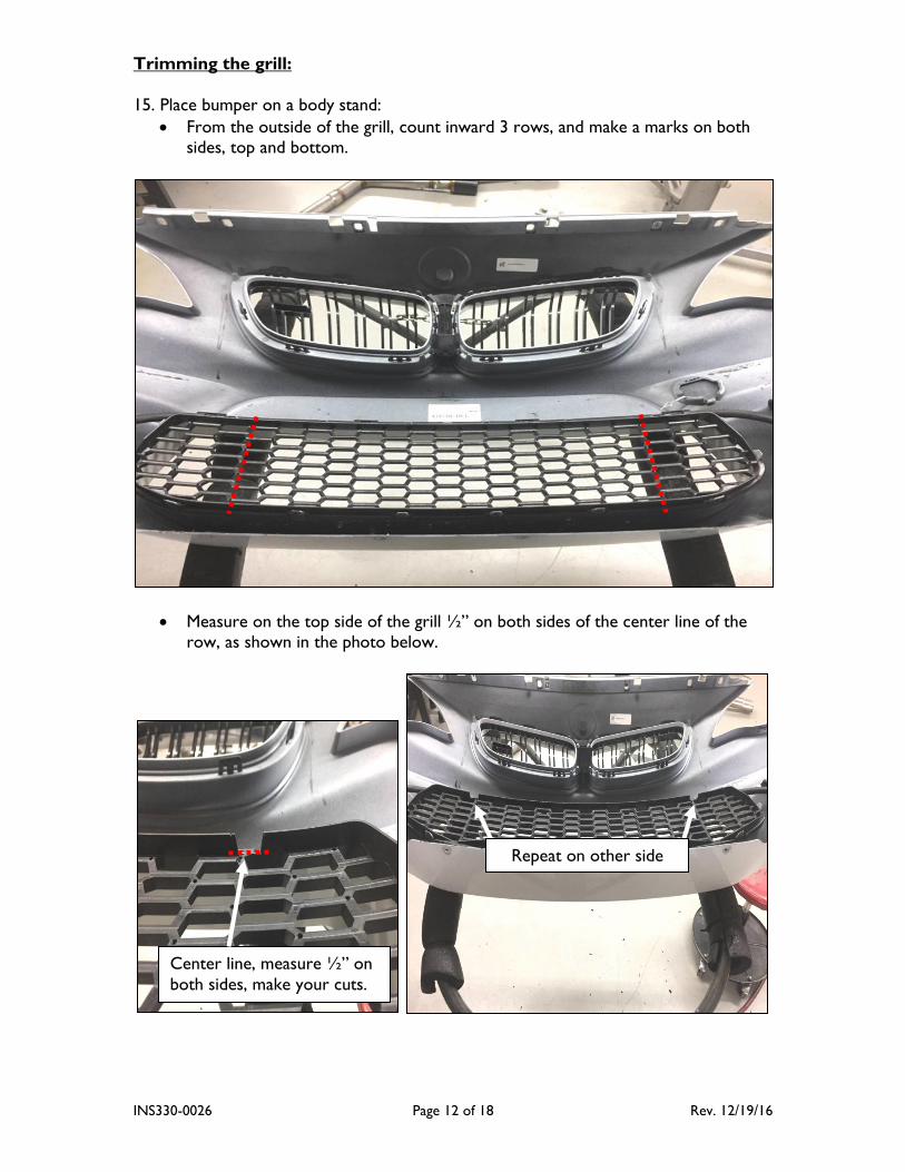
15. Place bumper on a body stand:
From the outside of the grill, count inward 3 rows, and make a marks on both sides, top and bottom.
Measure on the top side of the grill ½” on both sides of the center line of the
row, as shown in the photo below.
Center line, measure ½” on
both sides, make your cuts.
Repeat on other side
INS330-0026 Page 13 of 18 Rev. 12/19/16
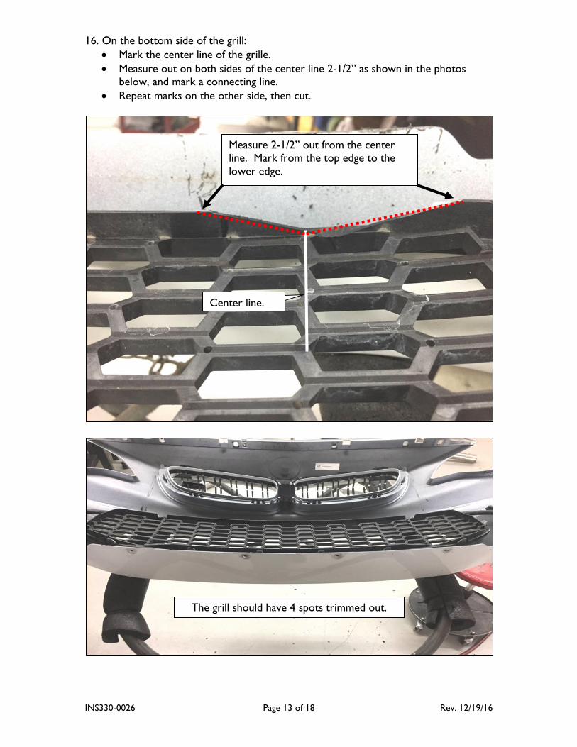
16. On the bottom side of the grill:
Mark the center line of the grille.
Measure out on both sides of the center line 2-1/2” as shown in the photos
below, and mark a connecting line.
Repeat marks on the other side, then cut.
The grill should have 4 spots trimmed out.
Center line.
Measure 2-1/2” out from the center
line. Mark from the top edge to the
lower edge.
INS330-0026 Page 14 of 18 Rev. 12/19/16
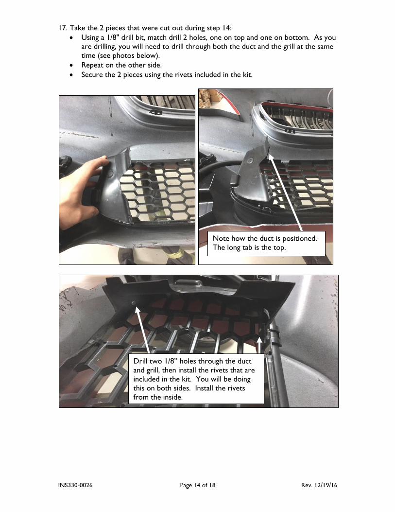
17. Take the 2 pieces that were cut out during step 14:
Using a 1/8" drill bit, match drill 2 holes, one on top and one on bottom. As you
are drilling, you will need to drill through both the duct and the grill at the same
time (see photos below).
Repeat on the other side.
Secure the 2 pieces using the rivets included in the kit.
Note how the duct is positioned.
The long tab is the top.
Drill two 1/8” holes through the duct
and grill, then install the rivets that are
included in the kit. You will be doing
this on both sides. Install the rivets
from the inside.
INS330-0026 Page 15 of 18 Rev. 12/19/16
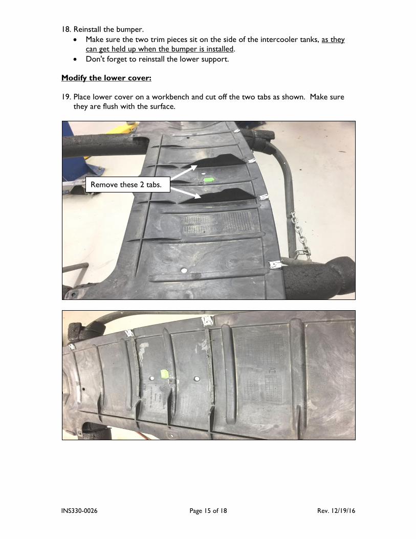
18. Reinstall the bumper.
Make sure the two trim pieces sit on the side of the intercooler tanks, as they
can get held up when the bumper is installed.
Don't forget to reinstall the lower support.
Modify the lower cover:
19. Place lower cover on a workbench and cut off the two tabs as shown. Make sure
they are flush with the surface.
Remove these 2 tabs.
INS330-0026 Page 16 of 18 Rev. 12/19/16
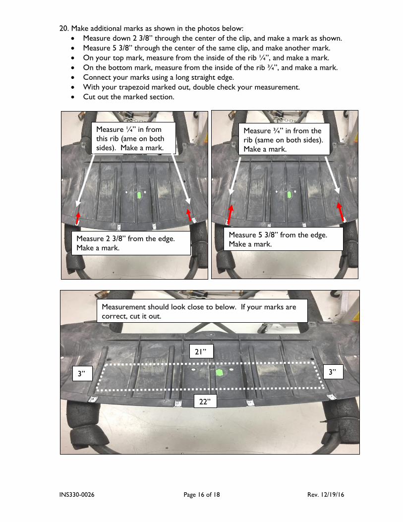
20. Make additional marks as shown in the photos below:
Measure down 2 3/8” through the center of the clip, and make a mark as shown.
Measure 5 3/8” through the center of the same clip, and make another mark.
On your top mark, measure from the inside of the rib ¼”, and make a mark.
On the bottom mark, measure from the inside of the rib ¾”, and make a mark.
Connect your marks using a long straight edge.
With your trapezoid marked out, double check your measurement.
Cut out the marked section.
Measure 2 3/8” from the edge.
Make a mark.
Measure ¼” in from
this rib (ame on both
sides). Make a mark.
Measure 5 3/8” from the edge.
Make a mark.
Measure ¾” in from the
rib (same on both sides).
Make a mark.
22”
21”
3” 3”
Measurement should look close to below. If your marks are
correct, cut it out.
INS330-0026 Page 17 of 18 Rev. 12/19/16
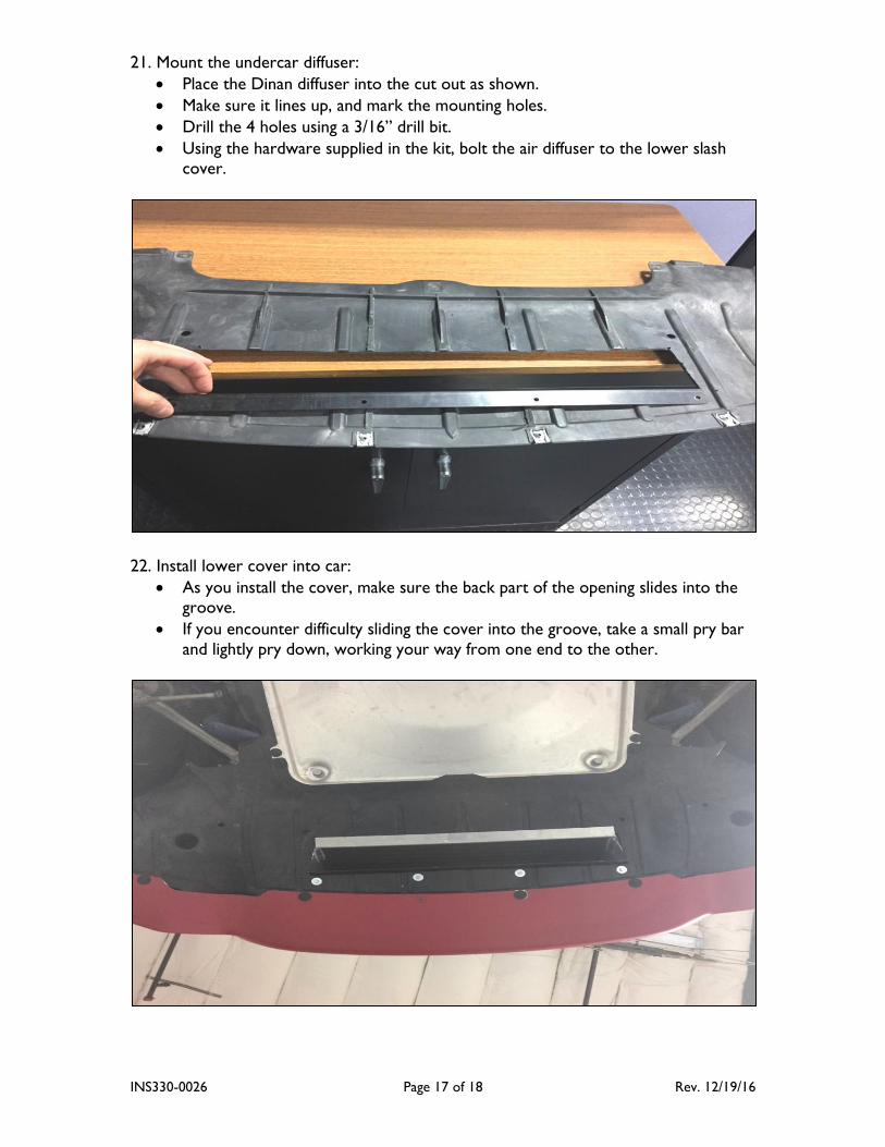
21. Mount the undercar diffuser:
Place the Dinan diffuser into the cut out as shown.
Make sure it lines up, and mark the mounting holes.
Drill the 4 holes using a 3/16” drill bit.
Using the hardware supplied in the kit, bolt the air diffuser to the lower slash cover.
22. Install lower cover into car:
As you install the cover, make sure the back part of the opening slides into the groove.
If you encounter difficulty sliding the cover into the groove, take a small pry bar
and lightly pry down, working your way from one end to the other.

INS330-0026 Page 18 of 18 Rev. 12/19/16
23. For best performance, please also install the appropriate DINANTronics ECU and
software.
24. Using a scan tool or equivalent, clear fault memory after installation is complete.
25. Happy Motoring!