Interconnection Requirements for Power Generators - 35 KV ... · 35 kV and Below Interconnection...
50
35 kV and Below INTERCONNECTION REQUIREMENTS FOR POWER GENERATORS May 2010
Transcript of Interconnection Requirements for Power Generators - 35 KV ... · 35 kV and Below Interconnection...

35 kV and Below
INTERCONNECTION REQUIREMENTS
FOR
POWER GENERATORS
May 2010
35 kV and Below Interconnection Requirements for Power Generators
Revision Date: May 2010
2
Table of Contents
1. Introduction 5 1.1 Scope 5 1.2 Copyright and Reprint 6 1.3 Disclaimer 6 1.4 Project Responsibilities 7
2. General Requirements 7 2.1 Point-of-Interconnection Considerations 7 2.2 Operating Voltage, Rotation and Frequency 8 2.3 Safety 9 2.4 Substation Grounding 10 2.5 Insulation Coordination 10 2.6 Station Service and Start-up Power 10 2.7 Isolating and Synchronizing 10
2.7.1 Isolation 10 2.7.2 Synchronization 11
2.8 Certification of the Power Generator’s Facility 11
3. Performance Requirements 11 3.1 Electrical Disturbances 11 3.2 Power Quality 12
3.2.1 Power Parameter Information System 12 3.2.2 Voltage Fluctuations and Flicker 12 3.2.3 Voltage and Current Harmonics 13 3.2.4 Phase Current and Phase Voltage Unbalance 14
3.3 Switchgear 14 3.4 Generators 14
3.4.1 Reactive Power Requirements 14 3.4.2 Excitation Equipment 16 3.4.3 Speed Governors 17 3.4.4 Voltage and Frequency Operation During Disturbances 17 3.4.5 Contingencies 18
3.5 Generator Transformers 18 3.6 Distribution Lines 19
3.6.1 Primary Voltage Distribution Line 20 3.6.2 Insulation 20 3.6.3 Primary Phase Conductors 20 3.6.4 BC Hydro Service Connection to Point-of-Interconnection (POI) 20 3.6.5 PG Private Line 20
4. Protection Requirements 21 4.1 General Requirements 21
4.1.1 Sensitivity and Coordination 21 4.1.2 Generator Distribution Line Protection 22 4.1.3 Equipment Rating 22

35 kV and Below Interconnection Requirements for Power Generators
Revision Date: May 2010
3
4.2 Service Entrance Protection 23 4.2.1 Protection with Relays and Circuit Breaker 24 4.2.2 Protection with Fuses and Loadbreak Switch 26
4.3 Off-Nominal Voltage Operation 26 4.4 Off-Nominal Frequency Operation 27 4.5 Electromagnetic Interference and Surge Withstand 27 4.6 Batteries / Chargers / DC Supplies 28
5. System Operating Requirements 28 5.1 Generation Shedding 28 5.2 Generation Islanding 28
5.2.1 Synchronous Generators 29 5.2.2 Induction Generators 29
6. Control and Telecommunications Requirements 29 6.1 General 29 6.2 Operations Control and Telecommunications Facilities 30 6.3 Telecommunications Media 30 6.4 Operating Data/Status Telemetering 30
7. REVENUE METERING 32
8. Commissioning Requirements 33 8.1 General 33 8.2 Commissioning Test 34 8.3 Protection Equipment 34 8.4 Telecommunications Equipment 34 8.5 Operating, Measurement and Control Systems 34 8.6 Apparatus 35 8.7 Generator(s) 35
9. Maintenance Requirements 35 9.1 General 35 9.2 Preventive Maintenance 35 9.3 Protection and Telecommunications Equipment 35
10. Regulatory and Reliability Requirements 36 10.1 WECC Reliability Requirements 36
35 kV and Below Interconnection Requirements for Power Generators
Revision Date: May 2010
4
Appendices
APPENDIX A Definitions 37
APPENDIX B CODES AND STANDARDS 38
APPENDIX C Protection COORDINATION Example 40
APPENDIX D POWER PARAMETER INFORMATION SYSTEM 41 D.1 General Description 41 D.2 Power Parameter Information System Requirements 41 D.3 Commissioning 41 D.4 Operation and Maintenance 41 D.5 PPIS Reference Drawings 42
APPENDIX E Data Requirements 44 E.1 Submission Requirements 44
APPENDIX F Declaration of CompatibIlity 46 F.1 Requirements for “Declaration of Compatibility – Load” 47 F.2 Requirements for “Declaration of Compatibility – Generator (1st Synchronization)”48 F.3 Requirements for “Declaration of Compatibility – Generator (Operating)” 49
APPENDIX G Permissible Voltage Dips - BorderLine of IRRITATION Curve 50
Tables
Table 1: Interrupting Ratings 22
Table 2: Response to Abnormal Voltages 27
Table 3: Off-Nominal Frequency Minimum Performance 27
Table 4: Generator Operating Data/Status Telemetry Summary 31
Figures
Figure 1: Entrance Protection One-Line 23

35 kV and Below Interconnection Requirements for Power Generators
Revision Date: May 2010
5
1. INTRODUCTION 1.1 Scope This document was prepared by BC Hydro (BCH) to guide generator owners and proponents in connecting generators to the BCH distribution system at 35 kV and below. It applies to all generators, whether utility or non-utility owned, and these generating plants are referred to as a Power Generator (PG).
The revisions from the February 2008 version to this February 2010 version are:
SECTION NUMBER
SECTION TITLE REVISION
1.1 Scope Scope of document extended to induction and inverter-based
generator technologies.
6.0 Operating Data/Status Telemetering
Compliance with current BC Hydro Engineering Standards.
8.0. Commissioning Requirements
Added requirement for 72-hour continuous commissioning test.
Appendix B
Codes and Standards Updated list of applicable standards.
Appendix D
Power Parameter Information System
Compliance with current BC Hydro Engineering Standards.
Appendix F.3 Declaration of Compatibility
Item 11 is replaced by 72-hour continuous test verification and conformity.
This document states the minimum technical requirements the Power Generator must meet and identifies expected system conditions the PG facilities could encounter while connected to the BCH system. Power Generator is defined as a resource that produces electricity and is connected and synchronized to the BCH system. The Power Generator may consume some or all of the generated electricity on site and/or it may sell some or all of the generated electricity.
These requirements will ensure that the PG’s equipment:
(a) is compatible with the BCH system, and that the interconnection is safe for BCH employees and agents, for BCH customers and for the general public, at all times,
(b) maintains a high standard of quality and reliability of electricity supply to BCH customers,
(c) meets BC Hydro operating, revenue metering and protection requirements, and

35 kV and Below Interconnection Requirements for Power Generators
Revision Date: May 2010
6
(d) is consistent with the required regulatory agencies and authorities, such as the British Columbia Utilities Commission (BCUC) and the Western Electricity Coordinating Council (WECC).
The two types of PGs connecting to the BCH distribution system are:
(a) Plants that export electricity to the BCH network by selling electricity to BCH or the market.
(b) Self-generation load displacement plants. These are BCH electricity customers with self-owned generation operating in parallel with the BCH supply, but no export to BCH across the BCH revenue meter. Examples are high technology companies that develop and test products.
This document applies to all induction (or asynchronous) and synchronous generators interconnected either directly or via inverters (or static power converters) to the BC Hydro distribution system at 35 kV and below. The document is geared to Power Generator plants rated > 500 kVA, up to a maximum of about 17 MVA, and interconnected at primary distribution voltage.
Some of the requirements in this document may also apply to:
(a) Inverter-based systems (solar PV systems, fuel cells) or systems which use an induction generator with a static power converter (wind turbines, regenerative dynamometers) or a permanent magnet generator with a static power converter (combustion micro-turbines).
This document does not apply to:
(a) Projects under the BC Hydro Net Metering Tariff (“BC Clean” to 50 kW). These projects have interconnection requirements specific to the Net Metering Tariff.
Web: http://www.bchydro.com/planning_regulatory/acquiring_power/net_metering.html
(b) Power Generators with closed-transition (make-before-break) transfer to/from BCH with a connected duration of up to 20 seconds. Requirements for these projects are specified in the BCH document: "Interconnection Requirements for Closed-transition Transfer of Standby Generators”.
Web: http://www.bchydro.com/planning_regulatory/acquiring_power/generator_interconnections.html
1.2 Copyright and Reprint Copyright © 2008 by BC Hydro.
Reprint Provisions:
(a) Copying all or any part of this document is permitted provided credit is given to BC Hydro and provided the copies of this document or parts thereof are not sold for profit.
(b) This document may be stored in any type of electronic retrieval system provided BC Hydro is clearly indicated as the source and provided no profit accrues from such storage.
1.3 Disclaimer This document is not intended as a design specification or as an instruction manual for the PG and this document shall not be used by the PG for those purposes. Persons using information included in this
35 kV and Below Interconnection Requirements for Power Generators
Revision Date: May 2010
7
guide do so at no risk to BC Hydro, and they rely solely upon themselves to ensure that their use of all or any part of this guide is appropriate in the particular circumstances.
The PG, its employees or agents must recognize that they are, at all times, solely responsible for the plant design, construction and operation. Neither BC Hydro nor any of their employees or agents shall be nor become the agents of the PG in any manner howsoever arising.
BC Hydro’s review of the specifications and detailed plans shall not be construed as confirming or endorsing the design or as warranting the safety, durability or reliability of the PG’s facilities. BC Hydro, by reason of such review or lack of review, shall be responsible for neither the strength, adequacy of design or capacity of equipment built pursuant to such specifications, nor shall BC Hydro, or any of their employees or agents, be responsible for any injury to the public or workers resulting from the failure of the PG facilities.
In general, the advice by BC Hydro, any of its employees or agents, that the PG’s plant design or equipment meets certain limited requirements of BC Hydro does not mean, expressly or by implication, that all or any of the requirements of the law or other good engineering practices have been met by the PG in its plant, and such judgement shall not be construed by the PG or others as an endorsement of the design or as a warranty, by BCH, or any of its employees.
The information contained in this document is subject to change and may be revised at any time. BCH should be consulted in case of doubt on the current applicability of any item.
1.4 Project Responsibilities The PG owns and is responsible for the design, installation, operation, and maintenance of all equipment, station and distribution line facilities from the Point-of-Interconnection (POI) to the PG facility, unless otherwise agreed to in writing. The PG is responsible for obtaining all regulatory approvals, including environmental assessment approvals, if necessary, for the construction and operation of its facilities. The PG facilities shall be designed, constructed, operated and maintained in compliance with the applicable statutes, regulations, by-laws and codes.
The PG is also responsible for submitting all specifications of its facilities and detailed plans to BCH for review prior to receiving permission to connect to BCH.
2. GENERAL REQUIREMENTS 2.1 Point-of-Interconnection Considerations The physical Point-of-Interconnection (POI) is determined after agreement between BC Hydro and the PG. This point is the wire ownership boundary between BC Hydro and the PG, and is the BCH side of the BCH service conductor/cable termination on the PG entrance disconnect switch.
Interconnection of generation projects into the BCH distribution system falls into one of two categories, as follows:
(a) The PG connects to a distribution circuit with BC Hydro load customers connected to the line. The PG owns and maintains the primary line from the POI to the PG site. This is the most common connection where the BC Hydro service voltage is primary voltage, i.e. from 4.16 kV to 35 kV. Alternatively, a PG might connect to a customer’s load bus at 600 V or less, where the BC Hydro service voltage is primary voltage or is secondary voltage at 600 V or less. Or
(b) The PG is connected via an express primary distribution line to a BC Hydro distribution substation bus,

35 kV and Below Interconnection Requirements for Power Generators
Revision Date: May 2010
8
i.e. no BCH load customers on the line. The PG owns and maintains the dedicated line, except BC Hydro owns and maintains the dedicated line where located on public road allowance, or is an overbuild of a BC Hydro line. Express circuit connection is rare, and the wire gauge for those parts of the express line owned by BC Hydro (if any) will not be greater than BC Hydro standard primary trunk line conductor, 336 kCM ASC.
2.2 Operating Voltage, Rotation and Frequency The BCH system operates at 60 Hz with an A-B-C counterclockwise phase rotation. BC Hydro's primary distribution system is a three-phase four-wire multi-grounded common neutral system, except 3-wire ungrounded in some limited locations.
The primary distribution voltages are:
(a) 2,400/4,160 V GRD Y,
(b) 7,200/12,470 V GRD Y,
(c) 14,400/24,940 V GRD Y,
(d) 19,920/34,500 V GRD Y currently used only in some rural locations in the Northern Region, stepped up from 14.4/25 kV in the field.
Standard distribution secondary voltages are 1-phase 120/240 V, 3-phase 3-wire 240 V (discouraged) and 3-phase 4-wire 120/208 V and 347/600 V. Older voltages are 3-phase 3-wire 480 V.
The LV bus at BCH distribution substations is generally regulated by station transformer automatic load tap changing (LTC), with a set point of about 124 V (7.44/12.89 kV or 14.88/25.77 kV), or by 3-phase 300/400 A feeder position voltage regulators or bus regulators, with a setpoint of 122-123 V. (120.0 V on a secondary basis is equivalent to BCH nominal primary voltages of 7.2/12.47 kV and 14.4/25.0 kV). Typical regulator bandwidth is +/- 1.5 V, and typical time delay varies from 30-70 seconds.
Steady-State Voltage BCH delivers electricity to consumer service entrances at a voltage according to CSA Standard CAN3-C235-83, “Preferred Voltage Levels for AC Systems, 0 to 50,000 V”, which defines steady-state voltage variation limits at consumer service entrances up to 1000 V as follows:
Variation From Nominal Voltage (on 120 Volt Base)
Normal Operating Extreme Operating
Range Range
Voltage at 1-Phase
120/240 V Service Entrance 110/220 - 125/250 V 106/212 - 127/254 V
The 2 ranges above do not apply under abnormal or fault conditions or temporary conditions such as magnetizing inrush currents and motor starting. Voltages outside the normal range but within the extreme range are corrected on a planned basis.
BCH Line Voltage Regulators
BCH uses automatic step voltage regulators in voltage-limited distribution feeders. Very long rural lines may have up to four line voltage regulators in series beyond the distribution substation. Introduction of a large PG (say 1 MVA and up) in a long rural feeder often results in both the real kW flow and reactive kvar

35 kV and Below Interconnection Requirements for Power Generators
Revision Date: May 2010
9
flow changing directions daily or seasonally in the BCH feeder. Line voltage regulators subjected to reverse power flow require controls and voltage sensing for reverse power tap changing. However, the regulator reference voltage is always the BCH distribution substation source bus voltage so the regulator always alters the feeder voltage profile with respect to the BCH source.
2.3 Safety Generators connected in parallel with the BCH distribution system must conform to the Canadian Electrical Code Part 1 (CSA C22.1-02) and BC Amendments where applicable. Section 84 covers the Interconnection of Electric Power Production Sources.
At the Point-of-Interconnection to the BCH System, the PG shall provide an isolating disconnect switch that physically and visibly isolates the BCH system from the PG. This applies whether the BCH service voltage is primary voltage or secondary voltage.
Safety and operating procedures for the isolating device shall be in compliance with the WorkSafeBC and the PG’s safety guidelines. Terms and conditions covering the control and operation of the disconnect device at the POI are covered by the BCH Local Operating Order prepared by the BCH Area Control Centre for signature by the PG.
BC Hydro Service Voltage at Primary Voltage
For BCH service voltage at primary voltage (4.16 kV to 35 kV), the PG disconnect device must be:
(a) rated for the voltage and current requirements of the particular development,
(b) gang operated,
(c) able to make and break the PG transformer magnetizing current,
(d) operable and accessible under all weather conditions in the area,
(e) be labeled with a BCH switch number,
(f) lockable in both the open and closed positions by a standard BCH padlock,
(g) key interlocked with the PG’s entrance breaker, where the BCH service voltage is primary voltage and the PG disconnect device is close to the PG’s powerhouse switchyard. Disconnecting interlocks shall be in accordance with the latest Canadian Electrical Code requirements, and
(h) installed with the hinge on the PG side and shall comply with CSA Standard C22.2 No. 193-M1983 (R2000), “High Voltage Full-Load Interrupter Switches”.
BC Hydro Service Voltage at Secondary Voltage
For BCH service voltage at secondary voltage (120 V to 600 V), the PG disconnect device must:
(a) be adequately rated to break the connected generation/load,
(b) be located within five meters (horizontal) of the POI, unless otherwise approved by BCH,
(c) provide a direct, visible means to verify contact operation,
(d) allow simultaneous disconnection of all ungrounded conductors of the circuit,
(e) plainly indicate whether the switch is in the “open” or “closed” position,
(f) be lockable in the “open” position by a standard BCH padlock,

35 kV and Below Interconnection Requirements for Power Generators
Revision Date: May 2010
10
(g) be capable of being energized from both sides,
(h) be readily accessible to BCH operating personnel,
(i) be externally operable without exposing the operator to contact with live parts,
(j) be capable of being closed without risk to the operator when there is a fault on the system,
(k) be labeled with a BCH switch number, and
(l) meet all applicable CSA Part II standards and all applicable codes.
2.4 Substation Grounding The equipment and station should be grounded in accordance with the latest Canadian Electrical Code. Ground conductor size, ground potential rise and step and touch potential calculations should be based on ultimate line-to-ground short circuit currents as specified by BCH for high voltage faults, unless exceeded by the PG’s low voltage short circuit currents.
2.5 Insulation Coordination Voltage stresses, such as lightning or switching surges, and temporary overvoltages may affect equipment duty. In general, PG stations with equipment operated at distribution primary voltage, as well as all PG transformers, should be protected against lightning and switching surges. Typically this includes station shielding against direct lightning strokes and surge arresters on all wound devices. Surge arresters are applied as close as possible to the equipment to be protected. Where they are applied, BCH revenue metering equipment should be located close enough to the arrester to be effectively protected.
Voltage ratings are as follows:
BCH System Voltage Arrester Rating
12.47kV 9 kV
25.0 kV 18 kV
34.5 kV 27 kV
2.6 Station Service and Start-up Power Power that is provided for local use at the PG site to operate lighting, heat and auxiliary equipment is the responsibility of the PG, but is normally provided from the BCH distribution system. The PG station service requirements, including voltage and reactive requirements, should not impose operating restrictions on the BCH system.
2.7 Isolating and Synchronizing
2.7.1 Isolation The PG shall not energize a de-energized BCH line unless the energization is specifically approved by BCH. If, for any reason, the PG is disconnected from the BCH system (fault conditions, line switching, etc.), PG re-synchronization to the live BCH distribution system is specified in the Distribution Operating Order (DOO).

35 kV and Below Interconnection Requirements for Power Generators
Revision Date: May 2010
11
2.7.2 Synchronization Induction generators do not require synchronization since there is no generated voltage prior to connecting to BCH. The generator speed is brought to within 0.5% of its rated value. These units may be started as induction motors using power from the BCH system provided that these units do not cause unacceptable voltage flicker on startup or on connect/disconnect.
For synchronous generators, an approved automatic synchronization device must be provided in all cases where the plant is to be operated unattended. Automatic synchronization shall be supervised by a synchronizing check relay, IEEE device 25. This assures the unit is not connected to the energized power system out of synchronization. If the plant is attended, the generator may be equipped with a manual synchronization device with relay supervision. The operator on site must have sufficient training to perform the function safely.
Synchronization controls should satisfy the following conditions for synchronous generators:
Aggregate Rating of Generators (kVA)
Frequency Difference
(Hz)
Voltage Difference (%)
Phase Angle Difference (degrees)
0-500 0.3 10 20 >500 – 1500 0.2 5 15 >1500 0.1 3 10
The BCH Area Control Centre will generally require the PG to contact the Control Centre before synchronization to the BC Hydro system can occur, as per the Local Operating Order.
2.8 Certification of the Power Generator’s Facility For PGs interconnected at primary voltage, a Professional Engineer, licensed in the Province of British Columbia, must declare that the PG’s facility has been designed, constructed and tested in accordance with the requirements stated in this document, project specific requirements as stated by BC Hydro, and prudent utility practice.
3. PERFORMANCE REQUIREMENTS The following performance requirements can be satisfied by various methods. It is the responsibility of the PG to provide the appropriate documentation and/or test reports to demonstrate compliance.
3.1 Electrical Disturbances The PG’s equipment should be designed, constructed, operated and maintained in conformance with this document, applicable laws/regulations, and standards to minimize the impact of the following:
(a) electric disturbances that produce abnormal power flows,
(b) overvoltages during ground faults,
(c) audible noise, radio, television and telephone interference, and
(c) other disturbances that might degrade the reliability of the interconnected BCH System.
35 kV and Below Interconnection Requirements for Power Generators
Revision Date: May 2010
12
3.2 Power Quality The operation of the PG's generator(s) should not degrade the quality of electricity in the BCH system.
3.2.1 Power Parameter Information System For PG plant ratings ≥ 1.0 MVA, BC Hydro requires a Power Parameter Information System (PPIS) to ensure power quality is maintained for on-line, off-line, steady and dynamic states. The PPIS is capable of high-speed sampling to capture information such as harmonics, and voltage and current levels. The information captured will allow BC Hydro and PG staff to assess the condition of electricity generating from the PG's facility.
BC Hydro will provide the system's requirements, including approved measurement devices (e.g. Power Measurement ION 7650) to the PG. The PG will supply, install and commission the PPIS at the PG's expense. If requested, BCH will perform these services at the PG's cost.
See Appendix D for details on the PPIS.
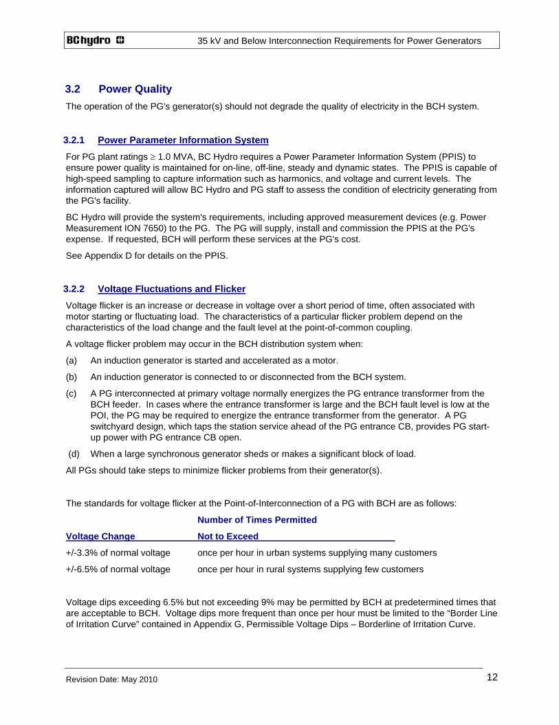
3.2.2 Voltage Fluctuations and Flicker Voltage flicker is an increase or decrease in voltage over a short period of time, often associated with motor starting or fluctuating load. The characteristics of a particular flicker problem depend on the characteristics of the load change and the fault level at the point-of-common coupling.
A voltage flicker problem may occur in the BCH distribution system when:
(a) An induction generator is started and accelerated as a motor.
(b) An induction generator is connected to or disconnected from the BCH system.
(c) A PG interconnected at primary voltage normally energizes the PG entrance transformer from the BCH feeder. In cases where the entrance transformer is large and the BCH fault level is low at the POI, the PG may be required to energize the entrance transformer from the generator. A PG switchyard design, which taps the station service ahead of the PG entrance CB, provides PG start-up power with PG entrance CB open.
(d) When a large synchronous generator sheds or makes a significant block of load.
All PGs should take steps to minimize flicker problems from their generator(s).
The standards for voltage flicker at the Point-of-Interconnection of a PG with BCH are as follows:
Number of Times Permitted
Voltage Change Not to Exceed
+/-3.3% of normal voltage once per hour in urban systems supplying many customers
+/-6.5% of normal voltage once per hour in rural systems supplying few customers
Voltage dips exceeding 6.5% but not exceeding 9% may be permitted by BCH at predetermined times that are acceptable to BCH. Voltage dips more frequent than once per hour must be limited to the “Border Line of Irritation Curve” contained in Appendix G, Permissible Voltage Dips – Borderline of Irritation Curve.

35 kV and Below Interconnection Requirements for Power Generators
Revision Date: May 2010
13
3.2.3 Voltage and Current Harmonics Harmonics can cause telecommunication interference and thermal heating in transformers. They can disable solid state equipment and create resonant overvoltages. In order to protect equipment from damage, harmonics must be managed and mitigated.
The harmonic content of the voltage and current waveforms produced by the PG should be restricted to levels which will not cause interference or equipment operating problems for BCH, its customers or telephone communication circuits. Generator auxiliary equipment, such as variable speed motor drives, are more likely to introduce harmonics into the distribution system than synchronous generators.
Single frequency and total harmonic distortion measurements may be conducted at the Point-of-Interconnection, PG site, or other locations on the BCH system to determine whether the PG’s equipment is the source of excessive harmonics.
The introduction of harmonics in the BCH system shall not exceed the following:
(a) In order to compare levels of harmonic distortion in a power system, the Total Harmonic Distortion (THD) is used, defined as the ratio of the RMS value of the harmonic to the RMS value of the fundamental voltage or current.
BCH follows the IEEE Standard 519-1992, "IEEE Recommended Practices and Requirements for Harmonic Control in Electric Power Systems". Section 10 describes the current distortion limits that apply to individual consumers of electrical energy. Table 10.3 lists the current distortion limits for distribution systems 120 V through 69,000 V.
Consumers with power generation equipment must limit Total Demand Distortion (TDD) to 5.0% at the point of common coupling (within an industrial plant, the point between the non-linear load and other loads). TDD is harmonic current distortion in % of maximum demand load current over 15 or 30 minutes.
Section 11 in IEEE 519 describes the quality of electrical power that the utility should provide the consumer. Table 11.1 lists a maximum total harmonic voltage distortion of 5.0% at the point of common coupling for systems 69 kV and below, with individual harmonic voltage distortion not to exceed 3.0%.
(b) Harmonic-caused telephone interference problems have limited correlation with I•T products. This guide imposes no design limits on the calculated I•T values. I•T denotes the inductive influence expressed as the product of the rms value of the current waveform (I) and the telephone influence factor (TIF) of the current waveform (T). TIF was developed to account for the frequency response characteristics of the coupling between the powerline and the telephone lines, the telephone system, and the human ear.
Telephone interference is, in many cases, caused by residual (zero sequence) harmonic currents. Also, indirect harmonic telephone interference may be caused by the interaction of non-residual harmonic currents with the supply system equipment. Since the indirect interference is impossible to predict in most cases, applying I•T limits, balanced or residual, serves little useful purpose.
Although no design limits are imposed, harmonic-telephone interference can be checked using measurement techniques. Telephone interference due to harmonics involves three major factors: the existence of the source of interference, the coupling between the source and telephone cable, and the susceptibility of telephone equipment. The I•T product only addresses the problem of the source of interference. The complexity of harmonic-telephone interference makes it impossible to accurately calculate the interference level with all three factors included. However, telephone interference measurements can be performed on any telephone set vulnerable to generator-induced harmonics, using indices adopted by the telecommunication industry. These measurements are the noise to ground and cable balance.

35 kV and Below Interconnection Requirements for Power Generators
Revision Date: May 2010
14
3.2.4 Phase Current and Phase Voltage Unbalance Most distribution feeders supply mainly single-phase loads and consequently all three phases are never equally loaded. Phase current unbalance of 10-20% and phase voltage unbalance up to 2-3% are considered "normal" supply conditions for distribution feeders.
Voltage unbalance in % is defined as
100 X (max deviation of any of the 3-phase voltages from average phase voltage)
(average phase voltage)
ANSI Standard C84.1-1995, Electric Power Systems and Equipment - Voltage Ratings (60 Hertz), recommends that the utility supply be designed and operated so that voltage unbalance does not exceed 3% at the utility revenue meter under no-load conditions. The voltage measurements are phase-to-phase, not phase-to-neutral.
The unbalance impact of PGs connected to 1-phase primary distribution limits the kVA rating of generation connected to the BCH 1-phase primary distribution lines. Single-phase generators must not adversely unbalance the three-phase system. A single-phase generator should not cause voltage unbalance on the distribution feeder in excess of two per cent.
Unbalanced phase voltages and currents can affect protective relay coordination and cause high neutral currents and thermal overloading of transformers. Of particular concern is negative sequence voltage and the resulting effect, particularly on rotating generators and motors connected to the system.
To protect BCH and customer equipment, the 3-phase PG’s contribution at the Point-of-Interconnection should not cause a voltage unbalance greater than 1% or a current unbalance greater than 5%. However, if the existing unbalance at the Point-of-Interconnection is shown to be already quite high, the PG’s contribution may cause the unbalance to exceed the specified amount. This will be considered case-by-case.
3.3 Switchgear Circuit breakers, disconnect switches, and all other current carrying equipment connected to BC Hydro’s distribution system shall be capable of carrying normal and emergency load currents without damage.
All PG entrance interrupting equipment (circuit breaker, recloser or fuses) shall have an interrupting rating equal to that in Table 1, Section 4.1.3. The circuit breaker should have this capability without the use of intentional time delay in clearing, fault reduction schemes, etc. Application should be in accordance with ANSI/IEEE C37 Standards. BCH will determine the existing and ‘ultimate’ fault duty at the POI.
The circuit breaker should be capable of performing all other required switching duties such as but not limited to: capacitive current switching, load current switching, and out-of-step switching. The circuit breaker should perform all required duties without creating transient overvoltages that could damage BCH equipment.
The PG entrance circuit breaker must have a rated interrupting time of 8 cycles or less.
3.4 Generators The generators should be designed in accordance with applicable standards and as specified below.
3.4.1 Reactive Power Requirements
Induction Generators

35 kV and Below Interconnection Requirements for Power Generators
Revision Date: May 2010
15
PGs using induction generators typically do not exceed the following plant ratings:
(a) approximately 200 kVA where the BCH primary service voltage is 1-phase 14.4 kV or 1-phase 19.9 kV,
(b) approximately 500 kVA where the BCH primary service voltage is 3-phase 25 kV or 3-phase 34.5 kV.
The maximum acceptable plant rating connecting to the 7.2/12.5 kV primary system will be determined case-by-case.
Induction generators have no inherent capability to control reactive power. Induction generators rated 35 kW and up shall provide shunt capacitor compensation to maintain generator output power factor at 90% or better at full rated power. If the selected shunt capacitor ratings exceed the limit for self-excitation of the generator, provision must be made to switch out the capacitors on sudden loss of load such as by a capacitor overvoltage relay or series resistor, to prevent sustained self-excitation and unpredictable voltage and frequency excursions.
Synchronous Generators Synchronous generators rated 500 kVA and up should be able to operate continuously at any power factor between 90% lagging (generating vars, overexcited) and 90% leading (absorbing vars, underexcited).
A PG at certain locations in the BCH distribution system may require a power factor rating of +/-0.80 in order to maintain the generator bus voltage within an acceptable range, considering the 8760-hour variation between feeder load and PG MW output. Determination of generator power factor rating depends on the PG MVA rating compared to the BCH feeder's annual maximum/minimum load, the length of the feeder and the PG location, and whether the generator is connected to an express or non-express feeder.
Synchronous Generators Rated 1.0 MVA & Up Synchronous generators rated 1.0 MVA and up will generally be required to operate year-round on voltage control, e.g. the PG control system maintains a stable generator bus voltage within +/-5% of rated voltage and sets excitation limits.
Where a synchronous generator rated 1.0 MVA and up cannot maintain a stable generator bus voltage at any time of the year, or for certain times of the year, BCH will accept a power factor control mode. The voltage/ power factor regulator must be capable of controlling the power factor of the generator between +0.90 and -0.90. BCH will determine the actual setpoint between these limits. In power factor control mode, the voltage regulator must have a voltage override that causes it to reduce excitation if the voltage at the POI exceeds an upper limit specified by BCH. The normal upper limit is 105 per cent of nominal; however, the voltage regulator must have provision to adjust this upper limit to between 100 per cent and 110 per cent of nominal. The voltage regulator must also have provision for a time delay between sensing an excursion of the upper voltage and initiating control action. The power factor control equipment must have provision to allow for the adjustment of this time delay between 0 and 180 seconds. BCH will specify the required time delay.
When operating at rated terminal voltage and within the generating unit’s complete range of output power, each generator shall be able to operate continuously in a range from an over-excited (lagging) power factor of 90% to an under-excited (leading) power factor of 90%. Under all ambient conditions, each generator must be able to operate continuously at its maximum power output and at rated field current and at any terminal voltage level within plus 10% and minus 10% of rated terminal voltage.
Synchronous Generators Rated > 10.0 MVA

35 kV and Below Interconnection Requirements for Power Generators
Revision Date: May 2010
16
If the BCH system operator does not have direct control over the generator's voltage regulator via supervisory control, the PG's operator must be able to respond and implement a BCH new Mvar output or voltage reference set point within 5 minutes.
The generator and its auxiliary equipment must be capable of operating for periods of at least 30 seconds at any generator terminal voltage level between 0.70 pu and 1.20 pu with the main circuit breaker open to allow the open circuit saturation test to be conducted.
With the generator initially operating at any point within its capability curve and at any terminal voltage level within +10% and -10% of nameplate, and without operator intervention, the generator must be able to withstand, for at least 30 minutes, a system disturbance that results in the generator terminal voltage dropping to 90% of the generator's rated terminal voltage.
With the generator initially operating at any point within its capability curve and at any terminal voltage level within +10% and -10% of nameplate, and without operator intervention, the generator must be able to withstand, for at least 30 minutes, a system disturbance that results in the generator terminal voltage rising to 110% of the generator's rated terminal voltage.
3.4.2 Excitation Equipment Synchronous generator excitation equipment shall follow industry best practice and applicable industry standards. Excitation equipment includes the exciter, automatic voltage regulator and over-excitation limiter.
For generator ratings 10.0 MVA and up, the excitation system should be a high initial response type as defined by IEEE Standard 421.4, capable of attaining 95% of the difference between the available ceiling voltage and rated load field voltage in 0.1 second or less. Ceiling voltage, defined as the maximum exciter voltage attainable under initial conditions of generator rated MVA, rated power factor, rated terminal voltage and rated speed, shall be greater than 3.0 pu. Negative ceiling voltage capability should also be provided. The excitation system shall be capable of producing the field current required for continuous operation at generator rated MVA, rated power factor, 1.10 pu terminal voltage and rated speed (“Excitation System Rated Current”). It shall also be capable of providing 1.6 times the excitation system rated current for 30 seconds (“exciter overload current rating”).
The PG shall provide a copy of all excitation system controls, limiters, and protective equipment settings to BC Hydro.
Excitation System Limiters For generator ratings 5.0 MVA and up, the excitation system must be equipped with limiters that are well coordinated with the generator protective relays. The limiter settings must not restrict the generator’s operating range (terminal voltage and Mvar limits) to less than 100% of the continuous capability of the equipment (i.e., the limiters must not overly protect the generating unit’s components at the expense of system security). The limiters must control the exciter output to avoid unnecessary operation of the generator’s protective relays in the event of any sudden abnormal system condition. In such a case, the AVR may to attempt to exceed the generator Mvar limits in its efforts to maintain the pre-set voltage reference point. Limiters should be of the non-windup type. The output of each limiter should immediately return to zero upon the elimination of the cause of the overload. Limiters should not switch the excitation system from automatic to manual voltage control.
Voltage Regulator For generator ratings 1.0 MVA and up, the generator exciter shall be equipped and operated with an automatic voltage regulator (AVR) set to control the generator terminal voltage. Under steady state
35 kV and Below Interconnection Requirements for Power Generators
Revision Date: May 2010
17
conditions, the AVR for generators rated 5.0 MVA and up shall be capable of automatically maintaining the generator terminal voltage, without hunting, to within plus or minus 0.1% of any set point within an operating range between plus 20% and minus 30% of the rated terminal voltage of the generator. This control range is for testing purposes only and is not meant to require that the generator and excitation equipment have the capability to operate for any significant length of time at these terminal voltage levels. Hydro-electric generators may undergo large speed changes during a sudden load change. The voltage regulators for these generators must maintain a linear characteristic with voltage variations restricted to less than 5% when machine speed varies from minimum to maximum anticipated value.
Induction Generator Resonance and Self-Excitation The PG owner should consider resonance in the design of the generation facility, as certain resonance can cause damage to electrical equipment, including the PG electrical equipment. Engineering analysis by the PG should be a part of the design process to evaluate the existence of, and to eliminate the harmful effects of ferroresonance in the PG transformer, and resonance with other customers' equipment due to the addition of shunt capacitor banks to the BCH distribution system. The adverse effects of self-excitation of the induction generator during island conditions must be assessed and mitigated. The intent is to detect and eliminate any self-excited condition. An engineering analysis of resonance and the assessment of the self-excitation effects of induction generators may be required by the PG.
3.4.3 Speed Governors Synchronous generators rated < 1.0 MVA require a speed governor - typically a hydraulic flyball with no remote signal.
Synchronous generators rated 1.0 MVA and up require a digital governor package on their prime movers. The frequency of the electric system is controlled by all synchronous generator governor systems that connect to the electric system. Governors must be operated unrestrained to regulate system frequency and to provide added system stability. Such governor systems respond automatically to changes in system frequency to prevent further deviation.
Governors should be capable of operating in droop or isochronous mode as required. Governors in droop mode shall be set to provide a 5% droop characteristic, i.e. if the generator were isolated from the interconnected system and its loading were raised from zero to 100% of its rated MW output, the generator frequency should drop by 5% (from 60 Hz to 57 Hz). The governor shall not have a deadband of more than 0.056 Hz.
The performance requirements for the governor system for operation in BCH should generally be in accordance with Section 4 of IEEE Standard 125 "IEEE Recommended Practice for Preparation of Equipment Specifications for Speed Governing of Hydraulic Turbines Intended to Drive Electric Generators" and with Section 4 of IEEE Standard 122 "IEEE Recommended Practice for Functional and Performance Characteristics of Control Systems for Steam Turbine-Generator Units.” Similar performance requirements shall apply to all types of prime movers (including reciprocating combustion engines and gas turbines).
3.4.4 Voltage and Frequency Operation During Disturbances Power system disturbances caused by system events such as faults and forced equipment outages expose connected generators to oscillations in voltage and frequency. It is important that larger synchronous generators remain in service for dynamic oscillations that are stable and damped. Over/under voltage and over/under frequency relays are installed to protect the generators and BCH customer loads from extended off-nominal operation. The required settings and time delays for these

35 kV and Below Interconnection Requirements for Power Generators
Revision Date: May 2010
18
relays are presented in the ‘Protection Requirements’, Sections 4.3 and 4.4.
Frequency Each synchronous generator rated 1.0 MVA and up must be capable of continuous operation at 59.5 to 60.5 Hz and limited time operation for larger deviations from normal frequency. Also, when system frequency declines, loads are automatically interrupted in discrete steps, with most of the interruptions between 59.5 and 57.5 Hz. Load shedding within the BCH system attempts to stabilize the system by balancing the generation and load.
Over/under frequency relays are normally installed to protect the generators from extended off-nominal operation. Larger synchronous generators shall remain connected to the system during frequency excursions. To ensure that the generator is not tripped prematurely, BCH will specify the minimum required time delays for setting the PG over/under frequency protection relays.
Voltage Each synchronous generator rated 1.0 MVA and up is to be capable of continuous operation from 0.90 to 1.10 pu of rated voltage. The clearing times for protection purposes are in Table 2, Section 4.3.
The nominal voltage levels available for connecting to BCH will depend on the location of the PG facility. Normal operating voltages on the BCH distribution system can vary by up to +/-10% of nominal voltage levels. The normal voltage level may vary over a wider range at certain locations, and larger variations will occur during abnormal or emergency conditions.
3.4.5 Contingencies The PG should adequately design and protect the generating plant against the impact of switching operations and contingencies in the BCH system. Some examples are as follows:
(a) Load rejection on the generating plant will cause overspeed and overvoltages in the PG facility. The amount of overspeed and overvoltage will be a function of the electro-mechanical parameters of the interconnected system and that of the generating plant.
(b) Self-excitation can occur where an islanded distribution/transmission system, left connected to the PG facility, represents a capacitive load in excess of the synchronous generator capability to absorb it. The PG facility may be damaged by the resulting overvoltage if the generator is not quickly disconnected from the distribution system. Where BCH substation or feeder shunt capacitors exist, BCH will assess the risk to its own and PG equipment due to voltage transients and resonance arising from capacitor bank switching.
(c) Acceleration of the generator during faults on nearby BCH distribution feeders could cause the generator to slip out of synchronism with the BCH system.
3.5 Generator Transformers A generator transformer is a step-up transformer that transforms generated voltage to a higher voltage for connection to a BCH distribution feeder. The transformer connection selected will affect BCH protective systems in terms of ground fault contribution, harmonic current flow and the use of single-phase or three-phase protection devices. PGs must submit their transformer connection proposal to BCH for approval before placing an order for purchase.
BCH recommends that PG transformers have off-load taps on the primary side with a minimum range of 2 x 2.5% above and below nominal voltage.
35 kV and Below Interconnection Requirements for Power Generators
Revision Date: May 2010
19
BCH will define the interconnection voltage and connection type for the PG transformer. The preferred transformer connection is grounded-wye on the BCH side and delta on the generator side. This connection offers more advantages than disadvantages. An exception to this connection method may be granted in some cases, e.g. a BCH load customer wishes to operate generation in parallel with the BCH supply system where a customer entrance transformer already exists. A common primary service connection to these customer load substations is HV delta/ LV grounded wye. One difficulty with this connection is PG detection of a SLG fault in the BCH feeder, when customer generation is in parallel with the BCH supply. Remedies to protect L-N connected customer equipment, surge arresters and BCH equipment from temporary or permanent L-N overvoltage upon opening of the BCH feeder CB are:
(a) PG installs a 3-phase grounding transformer, with CT(s), on the HV delta side. The grounding transformer is connected to the high voltage terminals of the entrance transformer without an isolating device. The grounding transformer shall be in the same zone of protection as the transformer, or
(b) PG installs a 59N ground fault overvoltage relay (zero sequence voltage relay) to the HV side via 3 VT’s wired with grounded-wye primary and broken delta secondary. However, this alternative has a risk that the generator can still supply an ungrounded system with damaging L-N overvoltages if the BCH protection clears the fault but the fault extinguishes before the PG’s protection operates.
To qualify as effectively grounded, the ratio of the zero sequence reactance to the positive sequence reactance (Xzero/Xpositive), as seen looking into the PG facility at the POI from the BC Hydro system with the generator operating, shall be equal to or less than 3.0, and the ratio of the zero sequence resistance to the positive sequence reactance (Rzero/Xpositive) not greater than one. For the purpose of calculating this ratio, the PG should use the generator’s direct axis transient reactance.
Although grounded-wye on the BCH side and delta on the generator side has a number of advantages for both BCH and the PG, the following points must be considered:
(a) Zero sequence currents originating in the BCH system will cause circulating currents in the delta winding of the transformer and their magnitude should be considered when determining transformer rating.
(b) The ground fault relays for the PG’s entrance CB must be connected to CT's on the BCH side of the transformer, since zero sequence current flows only in the primary side circuit.
(c) A line-ground fault near the PG results in a reduction in ground current to the BCH ground over-current relay. BCH may require the PG to install a neutral reactor between transformer primary star point and earth, to recover ground return current to the BCH ground overcurrent relay. This requires that the PG entrance transformer windings be insulated for line-to-line voltage at the neutral. The incoming BCH neutral conductor is connected to the earth side of this neutral reactor, and the reactor typically has an ohmic value of 1.0-1.5 times PG transformer zero sequence reactance. Impedance grounding also lowers transformer inrush current at the generator transformer. BCH does not accept resistor grounding because it marginally increases system losses, results in higher overvoltage on unfaulted phases and heat must be dissipated when ground current flows.
(d) If a ground fault occurs on the PG side of the transformer when the generator is not operating, no fault current flows on either side of the transformer and ground fault relays will not detect the fault. The remedy is voltage sensing relays on the PG side of the transformer.
3.6 Distribution Lines

35 kV and Below Interconnection Requirements for Power Generators
Revision Date: May 2010
20
3.6.1 Primary Voltage Distribution Line B.C. Hydro's primary overhead distribution is a three-phase four-wire multi-grounded common neutral radial system, but 3-wire ungrounded primary distribution exists in some limited locations.
BCH distribution feeders have a nominal current rating of 300 A. Feeder annual peak load may be > 300 A in urban areas (current-limited feeders), but is typically < 200 A in rural areas (voltage-limited feeders).
Urban feeders typically have 3-phase gang-operated line switches, fused 1-phase primary laterals and may have fixed and/or switched shunt capacitors. Rural feeders typically have fused 1-phase primary laterals and may have 3-phase gang-operated line switches, reclosers, sectionalizers, mainline fuses, voltage regulators, faulted circuit indicators and fixed and/or switched shunt capacitors.
3.6.2 Insulation BCH recommends that the BIL of the PG’s entrance equipment and transformer be compatible with the BIL of the BCH system, namely:
(a) 65 kV BIL on the 4.16 kV system,
(b) 95 kV BIL on the 12.5 kV system,
(c) 125 kV BIL on the 25 kV system,
(d) 150 kV BIL on the 34.5 kV system.
3.6.3 Primary Phase Conductors Primary phase conductors are generally selected to minimize long-term line losses and enhance line voltage regulation. Standard trunkline conductors are 336 kCM ASC and 266.8 kCM ACSR, with a 1/0 ACSR common neutral conductor.
3.6.4 BC Hydro Service Connection to Point-of-Interconnection (POI) BCH normally installs one span of O/H or U/G service conductor/ cable to a customer disconnect switch or mainswitch, whether connected at primary or secondary voltage. The POI is the BCH side of the BCH service termination on the customer switch. Terms and conditions covering the control and operation of this disconnect device are covered by the BCH Local Operating Order prepared by the BCH Area Control Centre for signature by the PG operator.
See Section 2.3 for PG entrance switch specifications.
3.6.5 PG Private Line A PG connecting to a BC Hydro distribution feeder through a line tap may require protection equipment at the BC Hydro side of the POI to maintain service reliability for the load customers. This line tap is normally privately owned and maintained. This Section defines the private line minimum reliability requirements and protection equipment requirements at the POI.
The private line shall cause little or no degradation in the target service reliability for the existing customers. The maximum allowable additional number of outages caused by faults on the private line is 5% of the target number of outages for the connected feeder.

35 kV and Below Interconnection Requirements for Power Generators
Revision Date: May 2010
21
The target reliability for the connected feeder can be classified as High, Medium, or Low based on the customer segment ranking for the specific feeder. Each rank has an acceptable number of outages. The target reliability is determined annually. The expected outage rate of the private line is determined from the connected feeder’s outage statistics, normalized to the length of the private line, along with other characteristics of the existing feeder. Different protection equipment may be required at POI based on PG ratings, expected private line reliability and target reliability for the connected feeder.
1) A fuse is acceptable at the POI if the fuse coordinates with feeder protection and can carry the PG output current.
2) For PGs that cannot be connected through a fused connection, a) if BC Hydro estimates the private line reliability will degrade the target service reliability for
existing customers, automatic line separation protection equipment (such as a recloser) is required at the POI.
b) if BC Hydro estimates the private line reliability will not degrade the target service reliability for existing customers, a solid link or solid blade can be used at the POI. If after PG is in service, the private line performance does not meet the requirement, a) will apply.
4. PROTECTION REQUIREMENTS 4.1 General Requirements BCH employs overcurrent and overvoltage (arresters) devices in the primary distribution system. The two main types of overcurrent devices used are line fuses and line reclosers. Overcurrent devices, when properly coordinated, reduce outages caused by temporary faults and minimize the number of customers affected by a permanent fault.
Surge arresters may be used to protect distribution lines from overvoltages caused by lightning surges, line-to-ground faults and switching operations.
Overall distribution feeder protection is provided by a circuit breaker or a recloser in the feeder position at the BCH distribution substation.
4.1.1 Sensitivity and Coordination The PG shall provide protection with adequate sensitivity to detect and clear all electrical faults on its premises, and coordinate with other BCH protection systems, considering present to ultimate fault levels. This protection is referred to as 'Entrance Protection'. In terms of this document, coordination is defined as either:
(a) fully selective clearing - the PG’s protection should clear all faults in the PG's installation before other relaying on BCH initiates tripping for such faults, or
(b) simultaneous clearing - the PG's protection should clear all faults in the PG's installation simultaneously with the clearing of such faults by BCH protection.
Alternative a) will apply for PG installations, unless protection requirements on the BCH system dictate that alternative b) must be used.

35 kV and Below Interconnection Requirements for Power Generators
Revision Date: May 2010
22
4.1.2 Generator Distribution Line Protection Since the PG contributes to faults on the BCH system, the PG shall provide equipment to clear phase and ground faults on the BCH distribution line. This protection is generally referred to as ‘Distribution Line Protection.’ Required fault clearing times will be specified by BCH.
The generation facility must be able to detect the following situations in the BCH feeder and isolate itself from the distribution system:
(a) a short circuit between any phase(s) and ground,
(b) a short circuit between phase(s), or
(c) loss of any phase(s).
Single-phasing of the three-phase primary service to a PG can occur due to broken conductors and/or protective equipment operation and the PG shall take measures to protect its plant.
The PG shall provide breaker failure protection for plants rated 1 MVA and up, via:
(a) CB auxiliary switch scheme, or
(b) current-based scheme, or
(c) remote back-up coverage via other relaying within the PG plant.
4.1.3 Equipment Rating The PG's equipment shall be rated to carry and interrupt the fault levels that are or will be available at the PG’s location - this includes the ultimate fault currents specified by BCH. The PG's equipment includes all its station and distribution facilities, including but not limited to all protection equipment forming the entrance and distribution line protection: current transformers, potential transformers, secondary cabling, dc system/battery charger, switchboard wiring and protective relays. If the equipment supplied is not designed for the ultimate fault duty, the PG assumes the responsibility for upgrading when necessary to accommodate changes to the system and the PG is responsible for contacting BCH to ensure their equipment is suitably rated. Ultimate fault levels are:
Table 1: Interrupting Ratings
Circuit Breakers & Reclosers
Fuses Fuses
Type of 3-Phase Service
Symmetrical MVA Asymmetrical rms Amperes
Symmetric rms Amperes
4.16 kV, 4-Wire 50 12,000 7,500
12.5 kV, 4-Wire 250 20,000* 11,500*
25 kV, 4-Wire 500 20,000* 11,500*
34.5 kV, 4-wire 300** 9,000 5,000
* where fuses are permitted and installed on outdoor pole top installations, the PG may install 12,000 A asymmetric cutouts (8,000 A symmetric),
** BC Hydro 35 kV distribution is stepped up from 25 kV in the field.

35 kV and Below Interconnection Requirements for Power Generators
Revision Date: May 2010
23
4.2 Service Entrance Protection The PG’s entrance circuit breaker shall be included in the entrance protection zone. That is, the relays shall connect to CTs on the BCH side of the circuit breaker, as shown in Figure 1.
BCH REVENUEMETERING
BC HYDRO PRIMARY DISTRIBUTION
PG MANUALGROUP OPERATEDLOAD-BREAKDISCONNECT SWITCH
K
ENTRANCEPROTECTION
SA
Figure 1: Entrance Protection One-Line
See Section 7.0 for revenue metering equipment locations.
BCH can provide the following feeder information:
(a) feeder maximum and minimum fault levels at the proposed POI,
(b) feeder annual maximum/ minimum load and feeder capacity,
(c) line and substation voltage regulator setpoint, bandwidth and time delay ,
(d) details on the setting and sequence of operation for substation feeder breakers, line reclosers and line fuses,
(e) feeder reliability records.
The following additional general requirements should be noted:
(a) Quality protection for BCH customer loads is required for all generating plants, i.e. under/over voltage and under/over frequency.
(b) Distribution feeders operate with varying unbalanced phase current. The PG’s equipment may be subjected to negative sequence current due to negative sequence unbalance in the distribution system. The PG is therefore encouraged to provide negative sequence (current unbalance)

35 kV and Below Interconnection Requirements for Power Generators
Revision Date: May 2010
24
protection (46) for generators.
(c) During emergencies or during abnormal operating situations on the BCH system, the PG may experience undervoltage or overvoltage conditions. PGs are encouraged to provide timed undervoltage tripping (27) and overvoltage (59) tripping to protect their equipment.
(d) BCH substation feeder circuit breakers are automatically reclosed in some locations and no auto reclose in other locations. Supervisory control of feeder breakers from the BCTC Area Control Centre is available in some cases. Additionally, automatic reclosers are common out in the feeder in rural areas. Line reclosing by BCH could connect an islanded PG to the BCH system when the two systems are out of synchronism. Out-of-phase switching can result in inrush currents up to 10 times the generator current rating. PGs shall provide generator protection for the possibility of an out-of-synchronism reclose from BCH line reclosers, automatic reclosing breakers and supervisory reclose of feeder breakers. Alternatively, BCH voltage supervision with synchronism check may be implemented at BCH line reclosers in the feeder. At BCH substations, feeder auto-reclose and manual close may have voltage supervision and synchronism check to prevent out-of-phase closing.
(e) Rural feeders may have fuses, reclosers and/or sectionalizers in the 3-phase mainline. The generator shall also be protected against possible single phasing on the feeder, which can occur in both rural and urban feeders.
(f) The primary and secondary side PG protection devices should withstand the maximum transformer inrush current during energization.
(g) When the PG installs surge arresters, they shall be installed as close as possible to the equipment they are protecting.
(h) Care should be taken in designing preventative and corrective interlock systems that all emergencies and contingencies can be dealt with.
4.2.1 Protection with Relays and Circuit Breaker PG plants rated 1.0 MVA and up must provide an entrance circuit breaker (CB) or recloser for protection tripping. An exception may be granted in certain cases, such as where a generator is added to an existing customer load facility which already has a main transformer and entrance fuses. The CB shall have an interrupting rating equal to or higher than the ultimate fault duty determined by BCH. The circuit breaker must also be capable of tripping the capacitive load of the incoming line and out-of-phase opening.
Current Transformers (a) BCH requires that the current transformers for entrance protection be connected between the PG
entrance disconnect switch and entrance CB, as in Figure 1. These CTs and associated protection relays trip the PG entrance CB for BCH feeder faults, and protect the entrance transformer for internal faults. If a draw-out type circuit breaker is used and the gang-operated disconnect switch is omitted, the relay CTs can be located on the PG side of the PG’s entrance circuit breaker.
(b) Current transformers shall have mechanical and thermal ratings adequate for the expected fault duty. For low ratio CT's, special designs may have to be ordered to achieve an adequate mechanical rating.
(c) Where current transformers and relays are used to provide overcurrent protection in conjunction with fuses, the fuses must limit the prospective short-circuit current to the mechanical rating of the current transformer.
(d) The current transformers shall be adequately rated to operate the relays and the breaker trip coil if an ac trip scheme is adopted, i.e. must perform adequately for all faults, including 3-phase faults. The success of the ac trip scheme depends primarily on the capability of the CT to provide enough energy transfer to the trip mechanism of the breaker when primary fault current is flowing under all

35 kV and Below Interconnection Requirements for Power Generators
Revision Date: May 2010
25
practical conditions. Saturation of the CT, with high impedance secondary circuits, can be experienced not only due to the dc component of the fault current, but also due to a high magnitude of ac symmetrical fault current. The secondary current through the trip coil under such conditions cannot always be assumed to be able to activate the breaker trip mechanism.
Relays BCH does not require the PG’s service entrance protective relays to be tested and approved by BCH, provided that the relays meet the minimum requirements specified in IEEE C37.90, “Standard for Relays and Relay Systems Associated with Electrical Power Apparatus”, latest edition. BCH reserves the right to require that the protective relays be tested for acceptability by an independent test facility. Utility grade, rather than industrial grade, protective relays are required for plants rated 1.0 MVA and up.
(a) The overcurrent relays may be arranged as three-phase relays or as two-phase relays and one ground relay. The latter arrangement is older equipment, while modern relays are typically 3-phase micro-processor based. A minimum time clearance of 0.4 seconds between the characteristics of the PG’s relay and the BCH feeder relay for maximum fault current at the PG’s installation shall be maintained.
(b) Differential relay protection alone on the PG’s main breaker is not acceptable. It must be accompanied with overcurrent protection.
(c) A large PG may introduce power swings resulting in out-of-step conditions for certain faults or contingencies in the BCH transmission system. If BCH determines that the swing centre is in the PG plant, the PG must detect and trip for out-of-step conditions and the applicable PG circuit breakers are rated for out-of-step switching.
(d) A set of test switches is required in each set of protection to provide isolation from current transformers, potential transformers and trip buses and to facilitate ac injection tests. A set of protection test switches is not required where this facility is built in to the relays.
Relays with self-diagnostic features provide information on the integrity of the protection scheme and should be used whenever possible. The protection scheme must be designed by a qualified engineer or a competent technical person to ensure the self-diagnostic feature is integrated into the overall protection scheme for the safe and reliable operation of the distribution system. Depending on the scheme and its design, where relays with the self-diagnostic feature do not trip the appropriate breaker(s), sufficient redundant or backup protection must be provided for the distribution system. The malfunctioning relay must also send a signal to notify operating personnel to investigate the malfunction.
Circuit Breakers Circuit breaker selection considers continuous current, voltage, fault interruption and out-of-phase switching, interrupting time, capacitive switching current, low temperature operations and proximity to transformers.
The PG entrance circuit breaker should have a rated interrupting time of 8 cycles or less. Circuit breakers may be equipped with either an ac trip coil or dc voltage shunt trip coil. If the latter is applicable the PG shall be responsible for adequate maintenance of its battery supply. If a stored energy voltage trip scheme is applied, such as a capacitor trip, the voltage supply for charging the capacitors will come from the source side of its associated circuit breaker.
See Section 4.6 for requirements to provide a secure breaker tripping power source.
An approved single shot recloser may be acceptable as a circuit interrupter.
35 kV and Below Interconnection Requirements for Power Generators
Revision Date: May 2010
26
4.2.2 Protection with Fuses and Loadbreak Switch Fuses are generally acceptable for entrance protection for PG plants rated less than 1.0 MVA.
Fuse Size Fuses shall have time-current characteristics that will coordinate with BCH service or line fuses.
BCH service fuses up to 100 A type T may be installed ahead of the primary service cable for an underground (U/G) dip connection. For an overhead connection, BCH service fuses up to 100 A type T may be installed on the branch tap or primary service ahead of the PG’s disconnect switch. For PG installations where the BCH line or service fuses do not exist, PG entrance fuses may have time-current characteristics up to 100 T.
It is not feasible to prepare a table of fuse sizes for each PG transformer size, but the following criteria serve as a guide:
(a) The fuse should be sized as small as possible and conform with the latest Canadian Electric Code and the BC Amendments.
(b) It should withstand magnetizing inrush current. This varies from 8 to 12 times the rated current of oil filled transformers for 0.1 to 0.2 seconds. The transformer design greatly affects the magnitude of the maximum inrush current.
(c) The fuse is to coordinate with the short time loading curve and the damage curve for the transformer.
(d) As a rule-of-thumb, the continuous current rating is 150-200% of transformer nominal current rating.
(e) It should coordinate with BCH fuses.
(f) For faults in the distribution feeder, generator protection should coordinate with the PG entrance fuses.
(g) The fuses must blow and clear all faults in the transformer and cables connecting the transformer to the generator breakers, before the BCH protection device trips.
4.3 Off-Nominal Voltage Operation The PG should operate its generation facility in such manner that the voltage levels on the BCH distribution system are in the same range as if the PG was not connected. The PG must install necessary relays to trip the circuit breaker when the voltage is outside predetermined limits.
For PG plant ratings 1.0 MVA and up, voltage-sensing VTs shall be phase to ground on all 3 phases on the HV side of the entrance transformer. Under-voltage relays shall be adjustable and shall have a settable time delay to prevent unnecessary tripping of the generator on external faults. Over-voltage relays shall be adjustable. The PG facility must cease to energize the BCH system within the clearing times indicated in the following table. “Clearing time” is the period of time between the start of the abnormal condition and the moment the interconnection device ceases to energize the BCH system, i.e. relay operating time plus CB operating time. The over-under-voltage protective relay settings in Table 2 are expressed in per cent of nominal BCH service voltage or nominal generator bus voltage.

35 kV and Below Interconnection Requirements for Power Generators
Revision Date: May 2010
27
Table 2: Response to Abnormal Voltages
% of Nominal Voltage Clearing Time
V < 50% 0.16 sec
50% < V < 90% 2.0 sec
90% < V <106% Normal Operation
106% < V < 120% 1.0 sec
V >= 120% 0.16 sec
Under/overvoltage trip settings and timing will be determined case-by-case for PG plants rated less than 1.0 MVA.
4.4 Off-Nominal Frequency Operation During off-nominal frequency excursions, synchronous generating units rated 1.0 MVA and up that are not susceptible to damage for the frequency ranges listed in Table 3 (e.g. typical hydro units), must remain on-line beyond the listed minimum requirements. Those units susceptible to damage will follow the minimum criteria in Table 3. Frequency relays must have a dropout time no greater than 2 cycles and shall be solid state or microprocessor technology. Relays with inverse time vs. frequency operating characteristics are not acceptable.
For generators rated 1.0 MVA and up, the frequency sensing is on the high-voltage side of the PG entrance transformer. Table 3: Off-Nominal Frequency Minimum Performance
Underfrequency Limit Overfrequency Limit Minimum Time
60.0-59.5 Hz 60.0-60.5 Hz Continuous
59.4-58.5 Hz 60.6-61.5 Hz 3 minutes
58.4-57.9 Hz 61.6-61.7 Hz 30 seconds
57.8-57.4 Hz 7.5 seconds
57.3-56.9 Hz 45 cycles
56.8-56.5 Hz 7.2 cycles
Less than 56.4 Hz Greater than 61.7 Hz Instantaneous
Under/overfrequency trip settings and timing will be determined case-by-case for PG plants with synchronous generators rated less than 1.0 MVA.
4.5 Electromagnetic Interference and Surge Withstand The influence of electromagnetic interference (EMI) must not result in a change in state or misoperation of the interconnection facility.

35 kV and Below Interconnection Requirements for Power Generators
Revision Date: May 2010
28
The interconnection facility must have the capability to withstand voltage and current surges in accordance with the environments described in IEEE/ANSI C62.41 or C37.90.1.
4.6 Batteries / Chargers / DC Supplies PG plants rated 1.0 MVA and up must ensure that the continuous dc supply voltage rating of any relay or its associated power supply is not exceeded due to sustained overvoltages on the dc supply bus. Common examples of conditions resulting in high, sustained overvoltages are:
(a) battery chargers at the equalize setting,
(b) battery chargers connected to the dc supply bus without the station batteries (not a recommended practice),
(c) battery chargers set in the constant current charging mode.
If there is any possibility that the dc rating of a relay will be exceeded, then a passive voltage regulator of suitable rating should be applied to each relay to limit the dc voltage to within the relay’s dc rating. Dual station batteries are not required for power protection and control equipment. A single dc supply is acceptable.
DC system requirements for PGs are as follows:
(a) Protection systems that are intended to back each other up will be supplied from dc circuits which are physically separated and separately protected. Also, power circuit breaker control circuits are to be supplied from dedicated and independently protected dc circuits.
(b) One undervoltage relay (set at least 5 V dc above the minimum acceptable voltage to operate the circuit breaker and associated protection and control circuitry) will be provided. The setting should be adjustable in case the dc requirements change, for example if equipment is added or replaced at a later date. Operation of this relay is to shut down the generator and open the HV circuit breaker to disconnect the PG from the BCH when the battery voltage dips to an unacceptably low level. A time delay is recommended for this trip initiation to override temporary voltage dips. This time delay shall not exceed 1 minute. This undervoltage tripping function is not required if the PG’s generating facility is manned 24 hours a day.
(c) One undervoltage relay, with time delay, to provide an alarm for battery charger failure or loss of ac supply. The voltage setting and time delay should be coordinated with the undervoltage tripping function described above.
5. SYSTEM OPERATING REQUIREMENTS 5.1 Generation Shedding Each generator or group of generators greater than or equal to 10 MVA is required to provide generation shedding equivalent to the amount of Wholesale Transmission Service (WTS) requested.
5.2 Generation Islanding Islanding is a condition where the power system splits into isolated load and generation following operation of a transmission CB, substation bus or feeder CB, distribution line recloser or line fuses . Generally, the “island” does not have a stable load to generation balance. PG islanding of BCH customer load may also result in voltage flicker, increased harmonic generation or miscoordination of protective devices if a fault

35 kV and Below Interconnection Requirements for Power Generators
Revision Date: May 2010
29
occurs during islanding. However, it is possible that, under unique situations, generator controls can establish a new equilibrium in the island. The island could be part or all of a distribution feeder, BCH distribution substation or a transmission line.
BC Hydro typically does not transfer trip from line reclosers or the substation feeder CB to the PG entrance protection.
To avoid the risk of damaging BCH customer equipment due to abnormal voltage or frequency during islanding, the PG should promptly automatically disconnect from the feeder when the PG becomes isolated from the BCH system. The intent of quality protection (over/under voltage and over/under frequency relays) is to initiate this PG disconnection.
The Local Operating Order specifies the return of PG parallel operation when BCH recovers from a feeder outage. For planned islanding, refer to “BC Hydro DISTRIBUTION POWER GENERATOR ISLANDING GUIDELINES”, June 2006.
5.2.1 Synchronous Generators Small PGs typically have limited turbine/generator control. However, the probability of an isolated system continuing to operate increases as the amount of isolated load approaches the capacity of the grid-connected generation.
5.2.2 Induction Generators An induction generator that has become separated from the BCH distribution system may be connected to an amount of shunt capacitance that will sustain self-excitation. Also, resonance may occur between the magnetizing inductance of the generator and the connected capacitance to produce damaging overvoltages.
Lightly loaded induction generators can produce an overvoltage of 2 pu or more on separation from the utility. Fast tripping of the generator by overvoltage protection may be required. In other cases, a slow rise in voltage but an instantaneous increase in frequency may occur if the isolated load is less than generator output. The slip will decrease instantaneously as the load suddenly drops, yielding a higher frequency and momentary increase in load as motors speed up. As motors reach their new speed the voltage rises. The voltage and frequency will continue to increase until the load has absorbed the entire generator output. For this case, tripping by fast overfrequency relays may be required.
6. CONTROL AND TELECOMMUNICATIONS REQUIREMENTS 6.1 General Control and telecommunications facilities, including those related to protective relaying, may be required at the PG premises and within the BCH system for safe and efficient operation of the power system and for the safety of personnel. This may include the upgrade of other BCH facilities.
All facilities and equipment defined in the following sub-sections must meet BCH approval to ensure that applicable standards and other considerations, such as functionality, proven reliability, and the availability of maintenance spares, are met. In some cases specific equipment may be defined in order to ensure compatibility with existing equipment such as Supervisory Control and Data Acquisition (SCADA) and other data monitoring master systems located at Area Control Centres and at the monitoring location.

35 kV and Below Interconnection Requirements for Power Generators
Revision Date: May 2010
30
6.2 Operations Control and Telecommunications Facilities Telecommunications facilities reporting to the BCTC System Control Centre (SCC) and/or regional Area Control Centres (ACC), and its backup Control Centre, may be required at the PG's premises for the operation of the power system within acceptable parameter limits. Facilities may include:
(a) digital and/or analog telemetering equipment,
(b) voice telecommunications for operating,
(c) data telecommunications for access to remote control and telemetry equipment,
(d) telecommunications media for the above, and
(e) suitable battery/charger systems for the above.
In most cases, a single analog business telephone dial-up line may be used to interrogate the main revenue meter, backup revenue meter, PPIS (Power Parameter Information System) equipment and provide telephone service. Exceptions are determined by BC Hydro. This is achieved by sharing a central line using a balanced telephone line-sharing device. A separate communication media is used for PG operating data/status to the BCTC Area Control Centre (Table 4 below).
6.3 Telecommunications Media Telecommunications media alternatives between the PG and BCH, and within BCH, for operating data/status may include dedicated or leased metallic wire line circuits, powerline carrier, microwave radio, fibre-optics and UHF/VHF radio. When two-way telecommunications media is required, full duplex (4 wire or equivalent) circuits will generally be used (except for standard voice telephone circuits on wire line, where 2 wire circuits are used).
Whenever metallic pairs are used, appropriate telecommunications entrance protection must be provided since the PG station ground potential can rise to hazardous levels above remote ground potential during a power system fault. Telecommunications entrance protection provides safety to personnel, prevents damage to equipment, and allows continuous use of the telecommunications media and the attached equipment during and after power system faults. This equipment should be designed to meet public carrier and BC Hydro safety and protective requirements.
6.4 Operating Data/Status Telemetering BC Hydro requires telemetering equipment for PG plants rated 1.0 MVA and up. Some or all of this data may need to be supplied continuously or via dial-up from the BCTC Area Control Centre or System Control Centre. The specific requirements depend on the size of the plant and other generation in the area. Telemetry information requirements are as follows:
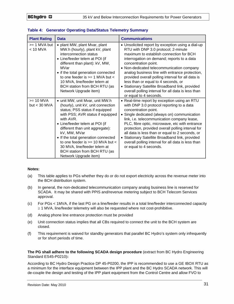
35 kV and Below Interconnection Requirements for Power Generators
Revision Date: May 2010
31
Table 4: Generator Operating Data/Status Telemetry Summary
Plant Rating Data Communications >= 1 MVA but < 10 MVA
• plant MW, plant Mvar, plant MW.h (hourly), plant kV, plant interconnection status
• Line/feeder telem at POI (if different than plant): kV, MW, MVar
• if the total generation connected to one feeder is >= 1 MVA but < 10 MVA, line/feeder telem at BCH station from BCH RTU (as Network Upgrade item)
• Unsolicited report by exception using a dial-up RTU with DNP 3.0 protocol; 2-minute maximum to establish connection for BCH interrogation on demand; reports to a data concentration point.
• Non-dedicated telecommunication company analog business line with entrance protection, provided overall polling interval for all data is less than or equal to 4 seconds, or
• Stationary Satellite Broadband link, provided overall polling interval for all data is less than or equal to 4 seconds.
>= 10 MVA but < 30 MVA
• unit MW, unit Mvar, unit MW.h (hourly), unit kV, unit connection status; PSS status if equipped with PSS; AVR status if equipped with AVR.
• Line/feeder telem at POI (if different than unit aggregate): kV, MW, MVar
• If the total generation connected to one feeder is >= 10 MVA but < 30 MVA, line/feeder telem at BCH station from BCH RTU (as Network Upgrade item)
• Real-time report by exception using an RTU with DNP 3.0 protocol reporting to a data concentration point.
• Single dedicated (always on) communication link, i.e. telecommunication company lease, PLC, fibre optic, microwave, etc with entrance protection, provided overall polling interval for all data is less than or equal to 2 seconds, or
• Stationary Satellite Broadband link, provided overall polling interval for all data is less than or equal to 4 seconds.
Notes:
(a) This table applies to PGs whether they do or do not export electricity across the revenue meter into the BCH distribution system.
(b) In general, the non-dedicated telecommunication company analog business line is reserved for SCADA. It may be shared with PPIS and/revenue metering subject to BCH Telecom Services approval.
(c) For PGs < 1MVA, if the last PG on a line/feeder results in a total line/feeder interconnected capacity ≥ 1 MVA, line/feeder telemetry will also be requested where not cost-prohibitive.
(d) Analog phone line entrance protection must be provided
(e) Unit connection status implies that all CBs required to connect the unit to the BCH system are closed.
(f) This requirement is waived for standby generators that parallel BC Hydro’s system only infrequently or for short periods of time.
The PG shall adhere to the following SCADA design procedure (extract from BC Hydro Engineering Standard ES45-P0210):
According to BC Hydro Design Practice DP 45-P0200, the IPP is recommended to use a GE IBOX RTU as a minimum for the interface equipment between the IPP plant and the BC Hydro SCADA network. This will de-couple the design and testing of the IPP plant equipment from the Control Centre and allow FVO to
35 kV and Below Interconnection Requirements for Power Generators
Revision Date: May 2010
32
prepare and precommission new RTU database with a test IBOX setup by the BC Hydro SCADA designer. The IPP SCADA designer shall follow Step 3b but with more Telecommunication options including dial-up, satellite and cellular data. The IPP SCADA shall discuss at the beginning of the project cycle with the BC Hydro SCADA designer to determine the technical details of the IBOX and submit technical information and IBOX configuration to enable the BC Hydro SCADA designer to complete the design at the Data Collection Point and pre-commission with FVO. If the IPP belongs to one of the BC Hydro pre-defined IPP type with a standardized DNP point list, a sample IBOX Configuration can be requested from the BC Hydro SCADA team for the IPP’s reference. After the project is in service, BC Hydro P&C SCADA designer will archive the RTU configuration according to BC Hydro Engineering Standards.
Step 3b. External consultant or IPP adding a new GE RTU.
At the beginning of the project cycle with a minimum of three months before the in service date, send the P&C scope document to the BC Hydro SCADA designer and request the following information needed to set up a new RTU in the BC Hydro system: DNP address, IP address, Data Collection Point, GE firmware version, GE BOOTROM version and GE Config Pro version. The network address assignment shall be made according to Design Practice DP 45-Q0022. The external consultant shall also request all the RTU drawing numbers from BC Hydro except for the R27 drawing number which will be reserved by the BC Hydro SCADA designer during archiving of the RTU configuration.
The external consultant shall submit to the BC Hydro SCADA designer the station LAN design architecture for review during the conceptual design phase of the project. The external consultant shall consult with the BC Hydro Telecommunications Department to ascertain whether direct RS232 connection or leased line dedicated modem connection will be used for the station involved. Based on that result, the external consultant shall request the BC Hydro SCADA designer to reserve either a direct connect RS232 port or a four wire modem port at the Data Collection Point (DCP).
The external consultant is responsible for all hardware design, RTU drawings, installation, testing and commissioning. The BC Hydro SCADA designer will be responsible for supplying the modem or the RS 232 connection at the DCP. The external consultant shall prepare a preliminary but tested version of the RTU Configuration and a preliminary version of the Point Assignment, and send them to the BC Hydro SCADA designer, together with all RTU drawings, P&C drawings and DNP point lists of all LAN devices, at least ten weeks before the in service date. The external consultant shall burn-in test the RTU configuration with the new RTU for a minimum of 72 hours before submitting it to BC Hydro. The BC Hydro SCADA designer will review the RTU Configuratoin, manage changes as required and perform pre-commissioning with FVO and put the final version of the RTU Configuration on a BC Hydro standard format CD for the Field and the consultant’s record. The external consultant, together with the Field crew and Station Manager, shall prepare the Alarm Change Request and submit to FVO for acceptance prior to commissioning. Commissioning will be the responsibility of the Field Services technicians, FVO and the external design consultant. After the project is in service, BC Hydro P&C SCADA designer will archive the RTU configuration according to BC Hydro Engineering Standards.
7. REVENUE METERING The Point-of-Delivery/Receipt (PODR) is the power custody transfer point and is typically located at, or near, the Point-of-Interconnection (POI) to the distribution system. The revenue metering is located at the Point-of-Metering (POM). Subject to approval by BC Hydro, the POM may be on either the BC Hydro side of the power transformer(s) or the PG side of the power transformer(s). When there are multiple power transformers, the POM is generally on the BC Hydro side of the power transformers to avoid multiple POMs. Where the POM is on the BC Hydro side of the power transformer(s), it shall be on the PG side of the service entrance disconnect device. Where the POM is on the PG side of the power transformer, a disconnect device shall not be installed between the power transformer and the POM. This is to insure that no-load losses are correctly registered whenever the power transformer is energized. If the POM is not located at the PODR, a loss compensation calculation is applied to account for the losses between the POM and the PODR.

35 kV and Below Interconnection Requirements for Power Generators
Revision Date: May 2010
33
Where two or more PG generation sites share one power line to connect to the BCH system at the same POI, an additional POM located at the POI will be required. For details about this “n+1 metering scheme”, refer to
Web: http://www.bchydro.com/youraccount/content/forms.jsp
Requirements for Remotely Read Load Profile Revenue Metering This document contains the requirements for remotely read load profile revenue metering. A main meter and a backup meter record the power delivered by BC Hydro to the Power Generator and the power received by BC Hydro from the Power Generator during each 30-minute time period. The revenue metering is read remotely by telephone.
Web: http://www.bchydro.com/youraccount/content/forms.jsp
Requirements for Manually Read Primary Service Voltage Revenue Metering This document contains the requirements for manually read BC Hydro distribution system primary service voltage class revenue metering. The meter records the power delivered by BC Hydro to the Power Generator and the power received by BC Hydro from the Power Generator.
Web: http://www.bchydro.com/youraccount/content/forms.jsp
Requirement for (Manually Read) Secondary (Voltage) Metering Installations (750 V and Less) This "stand alone" document contains the requirements for manually read secondary voltage revenue metering.
Web: http://www.bchydro.com/youraccount/content/forms.jsp
8. COMMISSIONING REQUIREMENTS 8.1 General The PG has full responsibility for the inspection, testing, and calibration of its equipment, up to the Point-of-Interconnection, consistent with the Interconnection Agreement. Commissioning must be performed by competent personnel. BCH shall be advised 10 days in advance of testing and may send a representative to witness tests.
PG plants that sell electricity to BC Hydro shall comply with the three Declarations of Compatibility defined in Appendix F prior to loading, synchronizing and operating. These declarations refer to key aspects where BCH must be confident of the correct operation, setting, calibration and/or installation of equipment. This may include, but is not limited to, generator performance, protective relaying, telecommunications, revenue metering, and shall confirm the compatibility of the PG’s equipment and controls with BC Hydro’s systems where applicable.
Commissioning tests confirm the safe, reliable and effective operation of all equipment in the PG’s facility under normal and abnormal conditions.
A BC Hydro Field Coordinator will be assigned to installations which sell electricity. To ensure compatibility, BCH personnel may:
(a) witness any part of the commissioning test,
(b) request additional testing and

35 kV and Below Interconnection Requirements for Power Generators
Revision Date: May 2010
34
(c) conduct their own testing.
Deficiencies identified during commissioning must be corrected before the interconnection is approved for operation. A copy of the commissioning reports signed and sealed by the Engineer of Record for the testing shall be submitted to BCH upon request.
8.2 Commissioning Test The PG commissioning shall include a continuous-operation test. The test will require the PG to operate for at least 72 hours in parallel with the BCH system in order to ensure operability of the PG and the distribution system protections.
The 72-hour continuous test shall be performed with a minimum PG capacity factor (generation output) specified by BCH, which shall not be less than 20% of the PG rated capacity.
8.3 Protection Equipment Commissioning of protection equipment should include but not be limited to:
(a) ratio, phase and polarity testing of current transformers and potential transformers,
(b) calibration checks of each protective relay by injecting the appropriate ac quantities,
(c) functional testing of the protective relays to circuit breakers and telecommunications equipment. Testing shall include minimum operating point verification for relays,
(d) load tests of protective relays immediately after initial energization, and
(e) verification of the transformer neutral reactor's ohmic value and correct connection, where applicable.
The settings applied to selected relays will be as determined or reviewed by BCH.
8.4 Telecommunications Equipment Functional end-to-end testing of telemetry, protection, alarms, voice, etc equipment is required.
8.5 Operating, Measurement and Control Systems Synchronization, governor, excitation, voltage regulator shall be proven, including generator load rejection tests at various generator output loads to 100%.
The ratio, phase and polarity of non-protection instrument transformers shall also be tested.
Revenue metering must be tested in accordance with Measurement Canada and BC Hydro requirements.
BC Hydro may witness the commissioning of the Power Parameter Information System (PPIS). Commissioning involves download and testing of the device configuration, check of instrument transform connections, UPS function test, and confirmation of dial-up connection and download of data.

35 kV and Below Interconnection Requirements for Power Generators
Revision Date: May 2010
35
8.6 Apparatus Commissioning of station apparatus equipment shall be performed in accordance with the Canadian Electrical Association's "Commissioning Guide for Electric Apparatus" or equivalent. Commissioning should include but not be limited to:
(a) power factor test of high voltage equipment at 10 kV to ensure insulation adequacy,
(b) timing and resistance test of main and/or generator circuit breaker(s),
(c) integrity checks of auxiliary switches, and
(g) continuity checks on control, power and protection cabling to equipment.
8.7 Generator(s) Generators rated 10 MVA and up require in-service testing and model validation to satisfy Western Electricity Coordinating Council (WECC) requirements.
9. MAINTENANCE REQUIREMENTS
9.1 General The PG has full responsibility for the maintenance of its equipment, up to the Point-of-Interconnection, consistent with the Interconnection Agreement. Maintenance must be performed by competent personnel.
Equipment used to control, generate, protect, and transmit electricity to BC Hydro shall be maintained such that the reliability of BC Hydro’s system is not adversely affected. BCH reserves the right to inspect and test the equipment given reasonable notice. The PG must perform necessary maintenance requested by BCH within a reasonable period.
9.2 Preventive Maintenance For PG plants rated 1.0 MVA and up, the PG should provide a plan to BCH for a preventive maintenance program for the electrical equipment. Maintenance should be based on time or on other factors, including performance levels or reliability, following the manufacturers' recommendations and/or accepted electric utility preventive maintenance practices.
9.3 Protection and Telecommunications Equipment Periodic maintenance of protection equipment shall include but not be limited to calibration testing of all protective relays and function testing to circuit breakers and telecommunications equipment at intervals of not more than 2 years.
Telecommunications equipment should be tested every 2 years.
Facilities to provide isolation from current transformers, potential transformers and trip buses and to allow ac injection tests should be provided.

35 kV and Below Interconnection Requirements for Power Generators
Revision Date: May 2010
36
10. REGULATORY AND RELIABILITY REQUIREMENTS All PGs connected to the BCH system must comply with all existing and future regulatory and reliability requirements imposed by various authorities, such as the British Columbia Utilities Commission (BCUC), and the Western Electricity Coordinating Council (WECC).
The authorities having jurisdiction over Power Generators connected to the BC Hydro system may change from time to time and the regulatory and reliability requirements may change from time to time. It is the responsibility of each PG to ensure it complies with current regulatory and reliability requirements. Any cost associated to comply with these authorities is the responsibility of the Power Generator.
10.1 WECC Reliability Requirements To ensure the safe and reliable operation of the western interconnected system, the Western Electricity Coordinating Council (WECC) provides reliability guidelines to which certain PGs connected to BCH must adhere. Certain PGs connecting to the BCH system will be required to formally agree to participate in the WECC’s Reliability Management System (RMS). PGs operating generators connected to the BCH system will be required to enter into a "Generator/Transmission Operator RMS Agreement", a model of which appears in Appendix B of the WECC RMS document entitled, "RMS Agreement to be entered into between the WECC and non-FERC-jurisdictional Transmission Operators within the WECC (includes the Generator Agreement).”

35 kV and Below Interconnection Requirements for Power Generators
Revision Date: May 2010
37
APPENDIX A DEFINITIONS
Area Control Centre (ACC) – Each ACC is responsible for the control and operation of an exclusive area of responsibility. BCH has four ACCs controlling four sections of the BCH grid system.
BCTC – British Columbia Transmission Corporation
BCH System – Encompasses the transmission lines, substations and distribution system operated by BC Hydro and BCTC.
British Columbia Utilities Commission (BCUC) – The BCUC is an independent provincial agency set up to regulate energy utilities in the province that distribute and sell electricity and gas.
Distribution – Electrical system operated at 35 kV and below.
Generation Site – the geographical location of the Power Generator(s) equipment. This may be near or far from the Point-of-Interconnection.
Interconnection Agreement (IA) – A legal document stating the contractual obligations between the PG and BCH. The document covers, but is not limited to, issues relating to facility ownership, operation, dispute mechanisms, and technical requirements. The Project Interconnection Requirements are an appendix to the IA.
Islanding - the condition when a portion of the BC Hydro system is energized by one or more PG facilities and that portion of the system is separated electrically from the rest of the BC Hydro system.
Point-of-Interconnection (POI) – The physical location in the Distribution system of the change of line ownership between BCH and the PG. The typical location is the BCH side of the BCH service termination on the PG entrance disconnect switch and is specified in the Interconnection Agreement.
Power Generator (PG) – A resource to produce electricity that is connected and synchronized to the BCH system. The Power Generator may consume all or some of the generated electricity on site or it may sell the generated electricity.
Primary Service – A BC Hydro service voltage of 4.16 kV, 12.5 kV, 25.0 kV or 34.5 kV
Secondary Service – A BC Hydro service voltage of 1-phase 120/240 V, or 3-phase 4-wire 120/208 V or 347/600 V
System Control Centre (SCC) – SCC dispatches generation and performs major system operating functions.
Transmission – Electrical system operated at 69 kV and above.
Western Electricity Coordinating Council (WECC) – Provides regional electric service reliability through: development of planning and operating reliability criteria and policies; the monitoring of compliance with these criteria and policies; the facilitation of a regional transmission planning process; and, the coordination of system operation through security centers. The territory of operation includes the western part of the continental United States, Canada, and Mexico. Some WECC requirements apply for individual synchronous generators rated 10.0 MA and up.
WECC Guidelines (http://www.wecc.biz/main.html)

35 kV and Below Interconnection Requirements for Power Generators
Revision Date: May 2010
38
APPENDIX B CODES AND STANDARDS
1. BC Hydro Requirements for Primary Substations Supplied at 12.0 kV and 25.0 kV
2. CSA Std C22.1, Canadian Electric Code Part I (Electrical Installation Code) and CSA Std C22.2, Canadian Electric Code Part II (Electrical Equipment) and CSA Std C22.3, Canadian Electric Code Part III (Electricity Distribution and Transmission Systems).
3. CSA Std C22.2 No. 31- M89 (R2000) Switchgear Assemblies. 4. CSA StdC22.2 No. 193-M1983 (R2000) High-Voltage Full-Load Interrupter Switches. 5. CSA Std CAN3 C235 83 (R2000) Preferred Voltage Levels for AC Systems 0 to 50,000V. 6. C37.04-1999 IEEE Standard Rating Structure for AC High-Voltage Circuit Breakers Rated on a
Symmetrical Current Basis (ANSI/DoD). 7. C37.06-1997 American National Standard for Switchgear--AC High-Voltage Circuit Breakers Rated
on a Symmetrical Current Basis--Preferred Ratings and Related Required Capabilities. 8. C37.09-1999 IEEE Standard Test Procedure for AC High-Voltage Circuit Breakers Rated on a
Symmetrical Current Basis (ANSI/DoD). 9. C37.010-1999 IEEE Application Guide for AC High-Voltage Circuit Breakers Rated on a Symmetrical
Current Basis. 10. C37.011-1994 IEEE Application Guide for Transient Recovery Voltage for AC High-Voltage Circuit
Breakers Rated on a Symmetrical Current Basis. 11. C37.013-1997 IEEE Standard for AC High-Voltage Generator Circuit Breaker Rated on a
Symmetrical Current Basis. 12. C37.1 ANSI/IEEE Standard Definitions, Specifications and Analysis of Systems Used for Supervisory
Control, Data Acquisition and Automatic Control. 13. C37.11-1997 IEEE Standard Requirements for Electrical Control for High-Voltage Circuit Breakers
Rated on A Symmetrical Current Basis. 14. C37.13-1990 (R1995) IEEE Standard for Low-Voltage AC Power Circuit Breakers Used in
Enclosures. 15. C37.16-1997 American National Standard for Switchgear - Low-Voltage Power Circuit Breakers and
AC Power Circuit Protectors-- Preferred Ratings, Related Requirements, and Application Recommendations.
16. C37.2 IEEE Standard Electrical Power System Device Function Numbers. 17. C37.20.1 ANSI/IEEE Standard for Metal-Enclosed Low-Voltage Power Circuit Breakers Switchgear. 18. C37.20.2-1999 IEEE Standard for Metal-Clad and Station-Type Cubicle Switchgear. 19. C37.20.3 ANSI/IEEE Standard for Metal-Enclosed Interrupter Switchgear. 20. C37.30-1997 IEEE Standard Requirements for High-Voltage Switches. 21. C37.51 ANSI Standard Conformance Test Procedure for Metal Enclosed Low-Voltage AC Power
Circuit-Breaker Switchgear Assemblies. 22. C37.52 ANSI Standard Test Procedures for Low-Voltage AC Power Circuit Protectors Used in
C37.58 ANSI Standard Conformance Test Procedures for Indoor AC Medium-Voltage Switches for Use in Metal-Enclosed Switchgear.
23. C37.90-1989 ANSI/IEEE Surge Withstand And Fast Transient Tests. 24. C37.90 ANSI/IEEE Standard for Relays and Relay Systems Associated with Electric Power
Apparatus. 25. C37.90.1-1989 (R1994) IEEE Standard Surge Withstand Capability (SWC) Tests for Protective
Relays and Relay Systems. 26. C37.90.2-1995 IEEE Standard Withstand Capability of Relay Systems to Radiated Electromagnetic
Interference from Transceivers.

35 kV and Below Interconnection Requirements for Power Generators
Revision Date: May 2010
39
27. C57.12 IEEE Standard General Requirements for Liquid Immersed Distribution, Power and Regulating Transformers.
28. C57.13-1993 IEEE Standard Requirements for Instrument Transformers. 29. C57.13.1 IEEE Guide for Field Testing of Relaying Current Transformers. 30. C57.13.2 IEEE Standard Conformance Test Procedures for Instrument Transformers. 31. C57.98-1993 IEEE Guide for Transformer Impulse Tests. 32. C57.116 ANSI/IEEE – Guide for Transformers Directly Connected to Generators. 33. C62.92.4-1991 IEEE Guide for the Application of Neutral Grounding in Electrical Utility Systems, Part
IV – Distribution. 34. C84.1-1995 ANSI Standard for Electric Power Systems and Equipment Ratings (60 Hertz). 35. IEEE Std C62.23-1995 Application Guide for Surge Protection of Electric Generating Plants. 36. IEEE Std 80 – Guide for Safety in AC Substation Grounding. 37. IEEE Std 81 – Guide for Measuring Earth Resistivity, Ground Impedance, and Earth Surface
Potentials of a Ground System. 38. IEEE Std. 100-2000 IEEE Standard Dictionary of Electrical and Electronics Terms. 39. IEEE Std. 125 – Recommended Practice for Preparation of Equipment Specifications for Speed
Governing of Hydraulic Turbines Intended to Drive Electric Generators. 40. IEEE Std 242-1986 Recommended Practice for Protection and Coordination of Industrial and
Commercial Power Systems. 41. IEEE Std 315-1975 (Reaffirmed 1993) ANSI Y32.3-1975 (Reaffirmed 1989) CSA Z99-1975 Graphic
Symbols for Electrical and Electronics Diagrams (including Reference Designation Letters). 42. IEEE Std 421-1 – IIEE Standard Definitions for Excitation Systems for Synchronous Machines. 43. IEEE Std 421-2 – Guide for the Identification, Testing and Evaluation of the Dynamic Performance of
Excitation Control Systems. 44. IEEE Std. 421-4 – Guide for the Preparation of Excitation System Specifications. 45. IEEE Std. 493-1900 IEEE Recommended Practice for Design of Reliable Industrial and Commercial
Power Systems (IEEE Gold Book). Chapter 9 deals specifically with voltage sag analysis and methods of reporting sag characteristics graphically and statistically.
46. IEEE Std 519-1992 IEEE Recommended Practice and Requirements for Harmonic Control in Electric Power Systems.
47. IEEE Std 1109 – Guide for the Interconnection of User-Owned Substations of Electric Utilities 48. IEEE Std 1159-1995 IEEE Recommended Practice for Monitoring Electric Power Quality. 49. IEEE Std 1547-2003 (R2008) IEEE Standard for Interconnecting Distributed Resources with Electric
Power Systems 50. IEEE Std 1547.1-2005 IEEE Standard Conformance Test Procedures for Equipment Interconnecting
Distributed Resources with Electric Power Systems. 51. IEEE Std 1547.2-2008 Application Guide for IEEE 1547, Standard for Interconnecting Distributed
Resources with Electric Power Systems. 52. IEEE Std 1547.3-2007 IEEE Guide for Monitoring, Information Exchange, and Control of Distributed
Resources Interconnected with Electric Power Systems. 53. CSA C22.3 No. 9-2008 Interconnection of Distributed Resources and Electricity Supply Systems. 54. CSA C22.2 No. 257-2006 Interconnecting Inverter-Based Micro-Distributed Resources to Distribution
Systems.

35 kV and Below Interconnection Requirements for Power Generators
Revision Date: May 2010
40
APPENDIX C PROTECTION COORDINATION EXAMPLE
Figure C1 shows the typical overcurrent coordination between the PG entrance protection and BC Hydro equipment, for a BC Hydro primary service with and without fuses.
35 kV and Below Interconnection Requirements for Power Generators
Revision Date: May 2010
41
APPENDIX D POWER PARAMETER INFORMATION SYSTEM
D.1 General Description
For PG plants rated 1.0 MVA and up, Power Parameter Information System (PPIS) equipment is required at the point of interconnection to monitor the individual power-line electrical parameters and generating system stability in real time on demand (machine system dynamics, kW, kvar, kV, kVA, PF, Hz, Harmonics, Flicker, Transients, Min, Max, Events, Outages, etc.) powered by an un-interruptible power supply (UPS) for a minimum of 8 hours of PPIS operation during power outages. BC Hydro will provide the system's requirements including approved measurement devices (e.g. ION 7650) to the PG. The independent PPIS monitor connects to protection grade 3-phase CT and VT windings. The PPIS monitor, telephone modem, test blocks, UPS, secondary wiring, etc. are mounted in a cubicle separate from the revenue metering cubicle. The monitor will be remotely accessed via a shared phone line. The PPIS system data may be linked to other data acquisition device.. An acceptable software package for PPIS remote access shall be supplied by the PG for free use by BC Hydro prior to commissioning. The PG shall supply and install the PPIS and BCH will verify the installation including the remote access function.
D.2 Power Parameter Information System Requirements
The PPIS consists of a multi-profile power meter with local display unit; protection grade voltage transformers (VT, 120V secondary) and current transformers (CT, 5A secondary); FT-1 type test blocks or alternatively, revenue type blocks; analogue business telephone line with facility entrance protection; telephone modem (set at 9600 Baud); RS232 modem cable; and an un-interruptible power supply (UPS). These components are interconnected to provide power parameter information via either the local display unit or remote access with application software acceptable by BC Hydro.
The full three-phase VTs and CTs (including optional transformer neutral CT when required) installed at the PG site are the input source to the power meter. The VT and CT test blocks are for testing and maintenance purposes, while the telephone modem provides remote access, and the UPS ensures minimum of 4 hours of PPIS operation during power outage. The PPIS system is preferably installed indoors in the control cubicle with front mounted local display unit, but may be located within the backup revenue metering cabinet if necessary.
D.3 Commissioning
The PPIS system shall be commissioned by the PG prior to generator operation. It shall be checked, tested and recorded for correct wiring, phasing, voltage and current levels, as well as functional tests for local and remote access by BC Hydro. PPIS configuration, programming, settings and recordings tasks are to be done by BC Hydro technical personnel.
D.4 Operation and Maintenance
BC Hydro will connect to PPIS on-line and/or periodic download the captured information. This system requires very low maintenance, however BC Hydro requires access to the system on site for inspection, testing and calibration purposes.

35 kV and Below Interconnection Requirements for Power Generators
Revision Date: May 2010
42
D.5 PPIS Reference Drawings

35 kV and Below Interconnection Requirements for Power Generators
Revision Date: May 2010
43
35 kV and Below Interconnection Requirements for Power Generators
Revision Date: May 2010 44
APPENDIX E DATA REQUIREMENTS
The following outlines data required at various stages for planning, design and commissioning the PG’s project. This data is required by BCH to ensure suitable steps are taken to interconnect the PG to the BCH system.
E.1 Submission Requirements
Wherever possible, all documents shall be provided in both paper and electronic form.
The preferred format for reports and other documents is Word for Microsoft Office 2003 and for data, drawing indexes and the like is Excel for Microsoft Office 2003.
The preferred formats for drawings are: (i) Auto-CADD *.DXF format, (ii) Intergraph MicroStation *.DGN format, or (iii) Portable Document Format (PDF).
Unless legibility will be a problem, all drawings must be submitted on either, ‘A’-size (8.5” x 11”; 21.6cm x 27.9cm), or 'B'-size, sheets (11” x 17”; 27.9 cm x 43.2 cm).
The Interconnection Application forms are available at: http://www.bchydro.com/interconnections/ For interconnection at primary voltage, items (a) through (c) are required for the BCH preliminary interconnection study. Larger PG projects on a weak BCH system may require more additional generator, exciter and speed governor data for the preliminary study:
(a) A map at a scale no greater than 50,000:1, preferably on B-size (43 cm X 28 cm paper), showing the proposed location of the generating station and existing BCH distribution line.
(b) Generating station electrical one-line diagram showing:
• the connections of all substation equipment with voltage levels and equipment ratings, with legend,
• all circuit breakers with applicable relay functions, plus fuses with fuse type and rating, from the POI to the generator(s),
• key interlock scheme where applicable, and
• the location of the revenue metering equipment.
(c) Generating station site plan showing the location of the generating plant and the proposed terminal pole or service manhole with the routing of aerial line or underground cables on private property to the generating station.
(d) Completed “Generator Equipment Statement”, “Service Entrance Equipment Statement”, “Application – Service Voltage 4 kV to 35 kV” or “Application – Service Voltage 120 V to 600 V”. These forms shall be signed and sealed by a registered B.C. Professional Engineer. The forms can be obtained at http://www.bchydro.com/info/ipp/ipp992.html.
(e) Protective device coordination study showing coordination between the generating plant and BCH protective devices. A standard size 4-½ x 5 cycle log-log graph shall be used for the coordination study. The plant’s service entrance protective device settings must be compatible and coordinate with BCH protective equipment. A simplified coordination graph is shown in Figure C1. The consultant normally enhances this sample and to produce a TC protection coordination graph for 3-phase faults and a separate TC graph for ground faults, each TC graph showing:
• PG transformer inrush current and damage curve,
• 4 vertical lines representing maximum and minimum short-circuit current contribution from the 2 sources for faults at the first BCH upstream protection device and the HV side of the PG

35 kV and Below Interconnection Requirements for Power Generators
Revision Date: May 2010 45
transformer, i.e. min generator contribution (fault at BCH protection device), max generator contribution (fault at PG terminal), min & max BCH contributions (fault at PG terminal),
• generator CB overcurrent curves,
• T-C curves for the nearest BCH upstream protection device, i.e. fuses or line recloser or BCH substation CB, including instantaneous setting where enabled.
35 kV and Below Interconnection Requirements for Power Generators
Revision Date: May 2010 46
APPENDIX F DECLARATION OF COMPATIBILITY
PG plants that sell electricity shall comply with the various levels of Declarations of Compatibility as listed below. These declarations refer to key aspects where BCH must be confident of the correct operation, setting, calibration and/or installation of equipment.
Each declaration must be signed by BC Hydro and the Power Generator agreeing that the PG’s Interconnection is compatible with the BC Hydro system and is capable of receiving electricity, generating electricity for commissioning purposes, or full commercial generating electricity. A copy of each declaration will be sent to the appropriate ACC in preparation for connection of Power Generator facilities to the BC Hydro Distribution system.
This may include, but is not limited to, generator performance, protective relaying, telecommunications, revenue metering, and shall confirm the compatibility of the PG’s equipment and controls with BC Hydro’s systems where applicable.
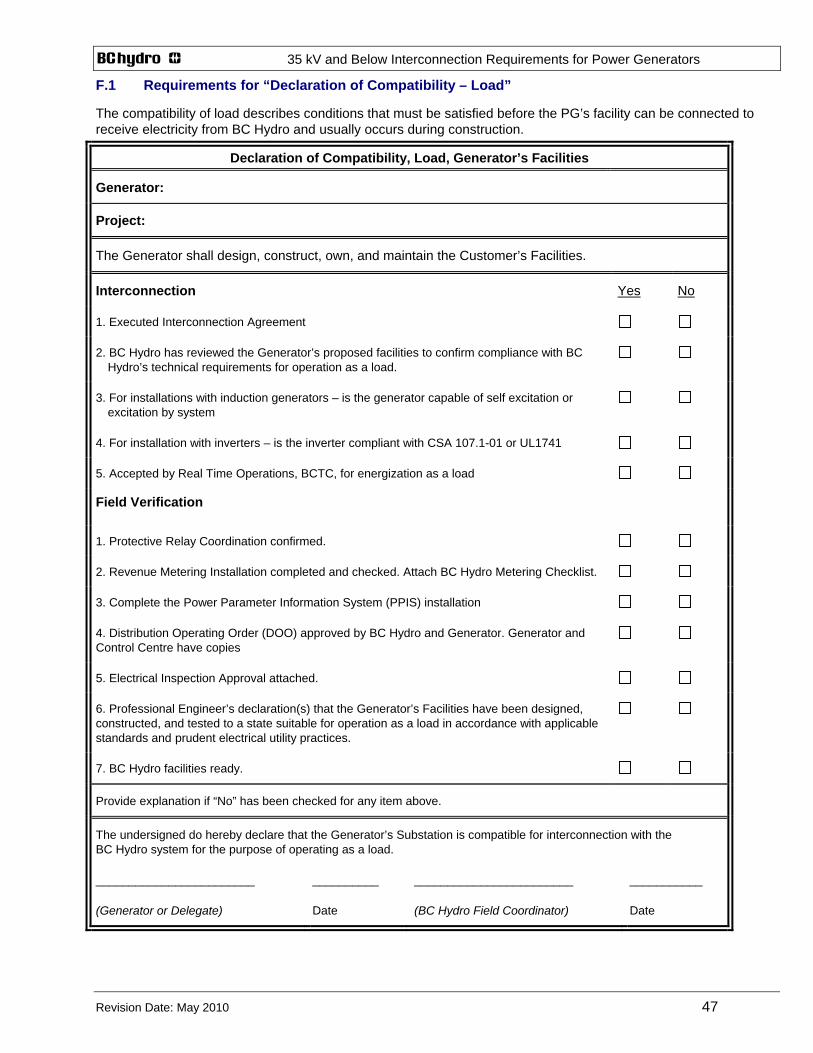
35 kV and Below Interconnection Requirements for Power Generators
Revision Date: May 2010 47
F.1 Requirements for “Declaration of Compatibility – Load”
The compatibility of load describes conditions that must be satisfied before the PG’s facility can be connected to receive electricity from BC Hydro and usually occurs during construction.
Declaration of Compatibility, Load, Generator’s Facilities
Generator:
Project:
The Generator shall design, construct, own, and maintain the Customer’s Facilities.
Interconnection Yes No
1. Executed Interconnection Agreement
2. BC Hydro has reviewed the Generator’s proposed facilities to confirm compliance with BC Hydro’s technical requirements for operation as a load.
3. For installations with induction generators – is the generator capable of self excitation or excitation by system
4. For installation with inverters – is the inverter compliant with CSA 107.1-01 or UL1741
5. Accepted by Real Time Operations, BCTC, for energization as a load
Field Verification
1. Protective Relay Coordination confirmed.
2. Revenue Metering Installation completed and checked. Attach BC Hydro Metering Checklist.
3. Complete the Power Parameter Information System (PPIS) installation
4. Distribution Operating Order (DOO) approved by BC Hydro and Generator. Generator and Control Centre have copies
5. Electrical Inspection Approval attached.
6. Professional Engineer’s declaration(s) that the Generator’s Facilities have been designed, constructed, and tested to a state suitable for operation as a load in accordance with applicable standards and prudent electrical utility practices.
7. BC Hydro facilities ready.
Provide explanation if “No” has been checked for any item above.
The undersigned do hereby declare that the Generator’s Substation is compatible for interconnection with the BC Hydro system for the purpose of operating as a load.
________________________
(Generator or Delegate)
__________
Date
________________________
(BC Hydro Field Coordinator)
___________
Date

35 kV and Below Interconnection Requirements for Power Generators
Revision Date: May 2010 48
F.2 Requirements for “Declaration of Compatibility – Generator (1st Synchronization)” The compatibility of generation (1st Synchronization) describes conditions that must be satisfied before the PG’s facility can be connected to generate electricity for the purposes of testing and commissioning the facility or its components.
Declaration of Compatibility, Generator (1st Synchronization), Generator’s Facilities
Generator:
Project:
The Generator shall design, construct, own, and maintain the Customer’s Facilities.
Interconnection Yes No
1. Executed Interconnection Agreement
2. BC Hydro has reviewed the Generator’s proposed facilities to confirm compliance with BC Hydro’s technical requirements for generator commissioning.
3. For installations with induction generators – is the generator capable of self excitation or excitation by system
4. For installation with inverters – is the inverter compliant with CSA 107.1-01 or UL1741
5. Accepted by Real Time Operations, BCTC, for energization for generator commissioning.
Field Verification 1. Protective Relay Coordination confirmed.
2. Revenue Metering Installation completed and checked. Attach BC Hydro Metering Checklist.
3. Complete the Power Parameter Information System (PPIS) requirement
4. Distribution Operating Order (DOO) approved by BC Hydro and the Generator. Generator and Control Centre have copies.
5. Electrical Inspection Approval attached (provided by BC Safety Authority or by an independent Professional Engineer registered in BC).
6. Professional Engineer’s declaration(s) that the Generator’s Facilities have been designed, constructed, and tested to a state suitable for commissioning (1st synchronization) in accordance with applicable standards and prudent electrical utility practices.
7. BC Hydro facilities ready.
8. Telemetry requirements complete
9. BCTC Operations approval to energize for generator commissioning received.
Provide explanation if “No” has been checked for any item above.
The undersigned do hereby declare that the Generator’s Substation is compatible for interconnection with the BC Hydro system for the purpose of generator commissioning.
________________________
(Generator or Delegate)
__________
Date
________________________
(BC Hydro Field Coordinator)
___________
Date

35 kV and Below Interconnection Requirements for Power Generators
Revision Date: May 2010 49
F.3 Requirements for “Declaration of Compatibility – Generator (Operating)”
The compatibility of generation (operating) describes conditions that must be satisfied before the PG’s facility can be connected to commercially generate electricity
Declaration of Compatibility, Generator (Operating), Generator’s Facilities
Generator:
Project:
The Generator shall design, construct, own, and maintain the Customer’s Facilities.
Interconnection Yes No
1. Executed Interconnection Agreement
2. BC Hydro has reviewed the Generator’s proposed facilities to confirm compliance with BC Hydro’s technical requirements for generator operation.
3. Accepted by Real Time Operations, BCTC, for energization for generator operation.
Field Verification
1. Protective Relay Coordination confirmed.
2. Revenue Metering Installation completed and checked. Attach BC Hydro Metering Checklist.
3. Distribution Operating Order (DOO) approved by BC Hydro and Generator. Generator and Control Centre have copies.
4. Completed the Power Parameter Information System (PPIS) requirements before the generator’s 72-hour continuous test.
5. Electrical Inspection Approval attached (provided by BC Safety Authority or by an independent Professional Engineer registered in BC).
6. Professional Engineer’s declaration(s) that the Generator’s Facilities have been designed, constructed, and tested to a state suitable for operation as generator in accordance with applicable standards and prudent electrical utility practices.
7. BC Hydro facilities ready.
8. Telemetry requirements complete.
9. BCTC Operations approval to energize for generator commissioning received.
10. WECC tests complete (synchronous generators 10 MVA and up)
11. Continuous 72-hour commissioning test successfully completed.
Provide explanation if “No” has been checked for any item above.
The undersigned do hereby declare that the Generator’s Substation is compatible for interconnection with the BC Hydro system for the purpose of generator operation.
________________________
(Generator or Delegate)
__________
Date
________________________
(BC Hydro Field Coordinator)
___________
Date

35 kV and Below Interconnection Requirements for Power Generators
Revision Date: May 2010 50
APPENDIX G PERMISSIBLE VOLTAGE DIPS - BORDERLINE OF IRRITATION CURVE