INTERCONEXION GENERACION FOTOVOLTAICA CON LA …€¦ · 1 interconexion generacion fotovoltaica...
16
1 INTERCONEXION GENERACION FOTOVOLTAICA CON LA RED DE DISTRIBUCION: CASO ESPECIAL GREEN CORNER JUNIO 2007 SUBDIRECCION DE DISTRIBUCION Y COMERCIALIZACION
Transcript of INTERCONEXION GENERACION FOTOVOLTAICA CON LA …€¦ · 1 interconexion generacion fotovoltaica...
1
INTERCONEXION GENERACION FOTOVOLTAICA CON LA RED DE DISTRIBUCION: CASO ESPECIAL
GREEN CORNER
JUNIO 2007
SUBDIRECCION DE DISTRIBUCION Y COMERCIALIZACION
2
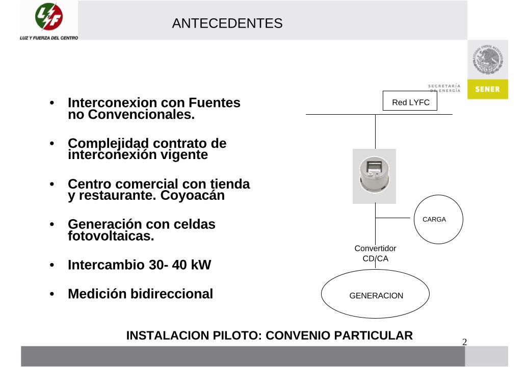
ANTECEDENTES
• Interconexion con Fuentes no Convencionales.
• Complejidad contrato de interconexión vigente
• Centro comercial con tienda y restaurante. Coyoacán
• Generación con celdas fotovoltaicas.
• Intercambio 30- 40 kW
• Medición bidireccional
CARGA
GENERACION
INSTALACION PILOTO: CONVENIO PARTICULAR
Convertidor CD/CA
Red LYFC
3
CONVENIO DE COLABORACION IIE LFC
• IIE estudia factibilidad de interconectar sistemas fotovoltaicospequeños para obtener información que sustente la normatividad aplicable.
• Solicita a LFC facilidades para conectar el servicio de The GreenCorner: trifásico, capacidad generación 30 kWp
• LFC atiende solicitud de interconexión con medición bidireccional. Green Corner hace trámite de Solicitud de Servicio
• Green Corner gestiona ante CRE permiso de intercambio de electricidad
• Green Corner paga a LFC sobre consumo neto• Diseño eléctrico cumple con los requisitos de seguridad requeridos
por LFC, revisado por IIE• IIE informa a LFC sobre comportamiento del sistema y las
mediciones correspondientes.
4
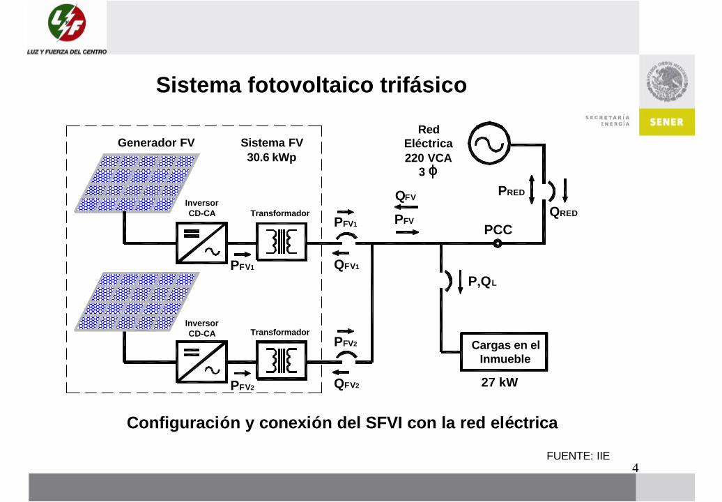
Sistema fotovoltaico trifásico
Configuración y conexión del SFVI con la red eléctrica
Generador FV Sistema FV30.6 kWp
TransformadorInversor CD-CA
Cargas en el Inmueble
27 kW
3
Red Eléctrica 220 VCA
TransformadorInversor CD-CA
PCC
O
PFV
PFV2
PFV1
QFV
P,QL
QRED
PRED
PFV1
QFV1
QFV2
PFV2
FUENTE: IIE
5
• Description• Utility Interactive Renewable Energy• Utility interactive, three-phase inverter, with models ranging from 30 kW to 225 kW. Multiple inverters may be
paralleled for larger power installations . • Designed for cost-effectiveness, high performance, easy installation, and reliability. • Advanced MPPT technology maximizes PV array output (not for use with batteries). • Revolutionaryswitching technology utilizes insulated gate bi-polar transistors (IGBT), greatly reducing power losses
during the conversion process. • Meets all applicable UL, IEEE, and NEC codes. • Listed by the CEC in California and by NYSERDA in New York. • Automatic operation includes start-up, shut-down, self-diagnosis, and fault detection.• Features• Efficient design, with over 95% peak efficiency for the inverter, and overall efficiency including transformer losses, in
excess of 93%. • Digital Signal Processor (DSP) based controls with self-diagnostics and LCD for display of operating status. • Inverter shut off and reset toggle switch.
• Over- and under-voltage and frequency protection, shutting down the inverter in compliance with UL1741.
• Anti-islanding protection - prevents back-feeding inverter-generated power to thegrid in the event of a utility outage.
• User definable power tracking matches the inverter to the array, as well as adjustable delay periods to customizesystem shut-down sequences.
FUENTE: XANTREX
ESPECIFICACIONES INVERSORES
6
ESPECIFICACIONES INVERSORES
• PV30 Electrical Specifications
• Continuous Power Rating 30 kW• Nominal AC Voltage 208 VAC Three-
phase, +10% / -12%• Nominal AC Frequency 60 Hz +0.5 Hz
/ -0.7 Hz• Line Power Factor >0.99 Above 20%
rated power• Maximum AC Line Current 94 amps
AC• AC Current Distortion <5% THD
at rated power• Max. Open Circuit Voltage 600 VDC• Power Tracking Window Range 330 to
600 VDC Max. • DC Input Current 100 amps DC CEC
Efficiency 92% (208V and 480V)• Peak Inverter
Efficiency >95% Standby Tare Losses <30 watts
• General Specifications
• Temperature Range: Ambient -4° F to 122° F (-20° C to 50° C)
• Storage -40° F to 122° F (-40° C to 50° C)
• Enclosure EnvironmentalRating NEMA3R
• Enclosure Galvaneal folded steelenclosure
• Weight 260 lb (118 kg) Dimensions (H x W x D) 54 x 36 x 19" (137 x 91 x 48 cm)
• Altitude 6,600' (2,012 m)• Relative Humidity 0 to 95% non-
condensing• Array Configuration Monopole,
negative or positive grounded
FUENTE: XANTREX
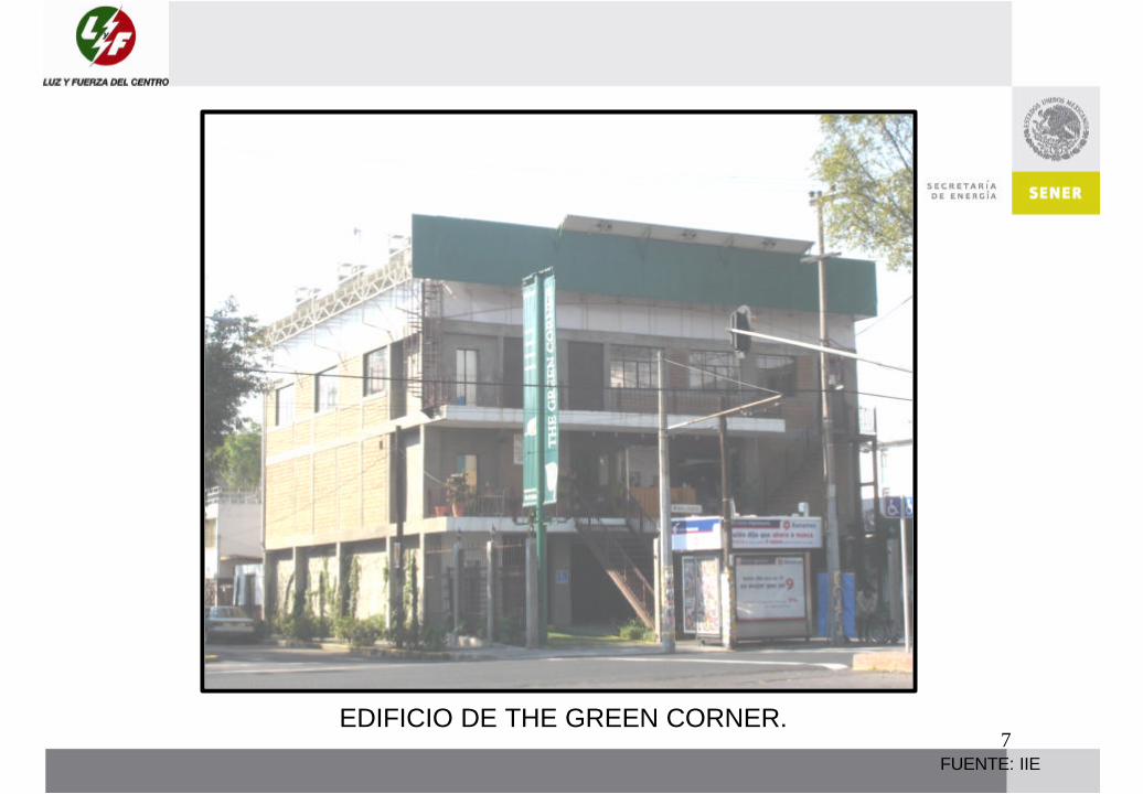
7EDIFICIO DE THE GREEN CORNER.
FUENTE: IIE
8
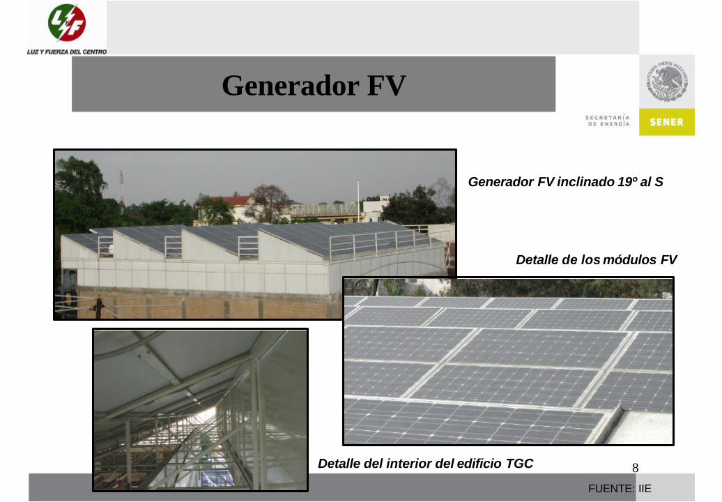
Generador FV
Generador FV inclinado 19º al S
Detalle del interior del edificio TGC
Detalle de los módulos FV
FUENTE: IIE

9
Inversores e Interfaz con la red
Transformadores de AislamientoDelta-Estrella
FUENTE: IIE
10
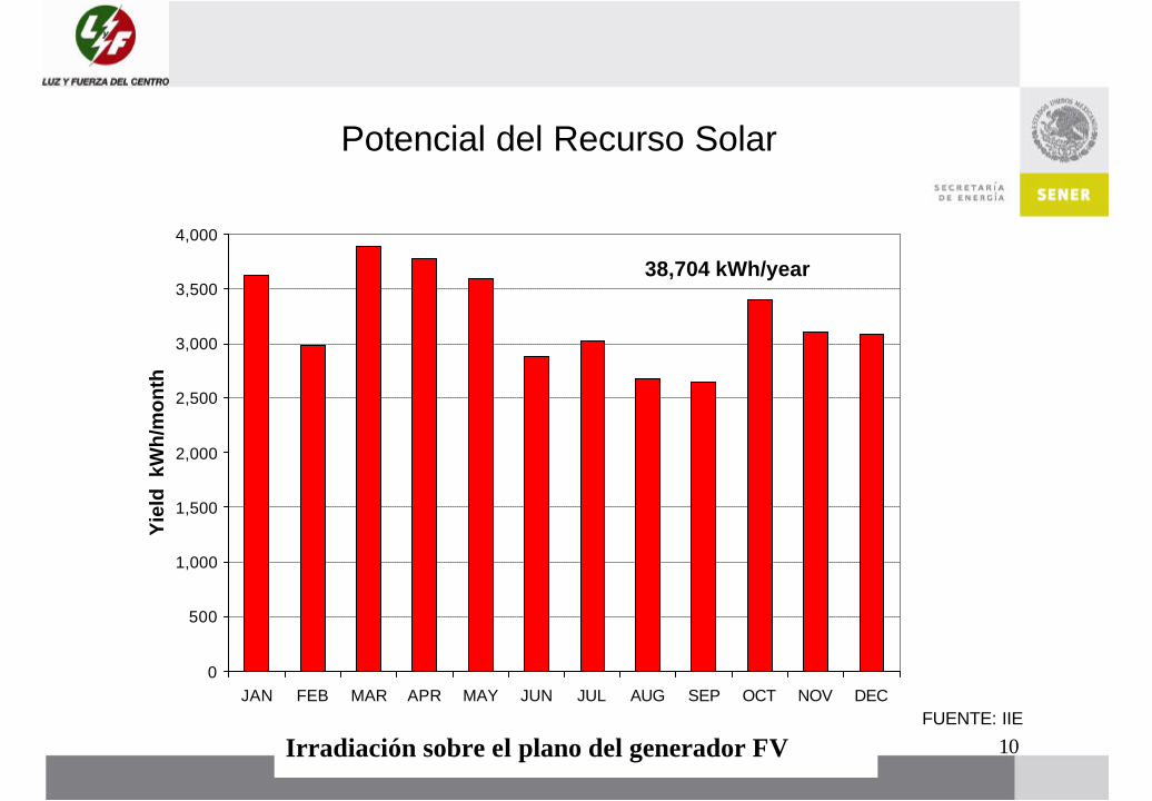
0
500
1,000
1,500
2,000
2,500
3,000
3,500
4,000
JAN FEB MAR APR MAY JUN JUL AUG SEP OCT NOV DEC
Month
Yie
ld k
Wh
/mo
nth
38,704 kWh/year
Irradiación sobre el plano del generador FV
Potencial del Recurso Solar
FUENTE: IIE

11
Reducción de la demanda de la red por la generación FV
FUENTE: IIE
-5
0
5
10
15
20
25
1 2 3 4 5 6 7 8 9 10 11 12 13 14 15 16 17 18 19 20 21 22 23 24
Hora
Pot
enci
a R
eal (
kW
)
-30
-20
-10
0
10
20
30
Tem
pera
tura
Am
b. (
°C)
Demanda sin FV Generación FV Demanda con FV Temperatura Amb.

12
Flujos de potencia activa y reactiva
FUENTE: IIE
-10
-5
0
5
10
15
20
1 2 3 4 5 6 7 8 9 10 11 12 13 14 15 16 17 18 19 20 21 22 23 24
Hora
Po
ten
cia
Rea
l y R
eact
iva
(kW
, kV
AR
)
-50
-25
0
25
50
75
100
Fac
tor
de
Po
ten
cia
(%)
Potencia Real PCC Potencia Reactiva PCC Factor de potencia
13FUENTE: IIE
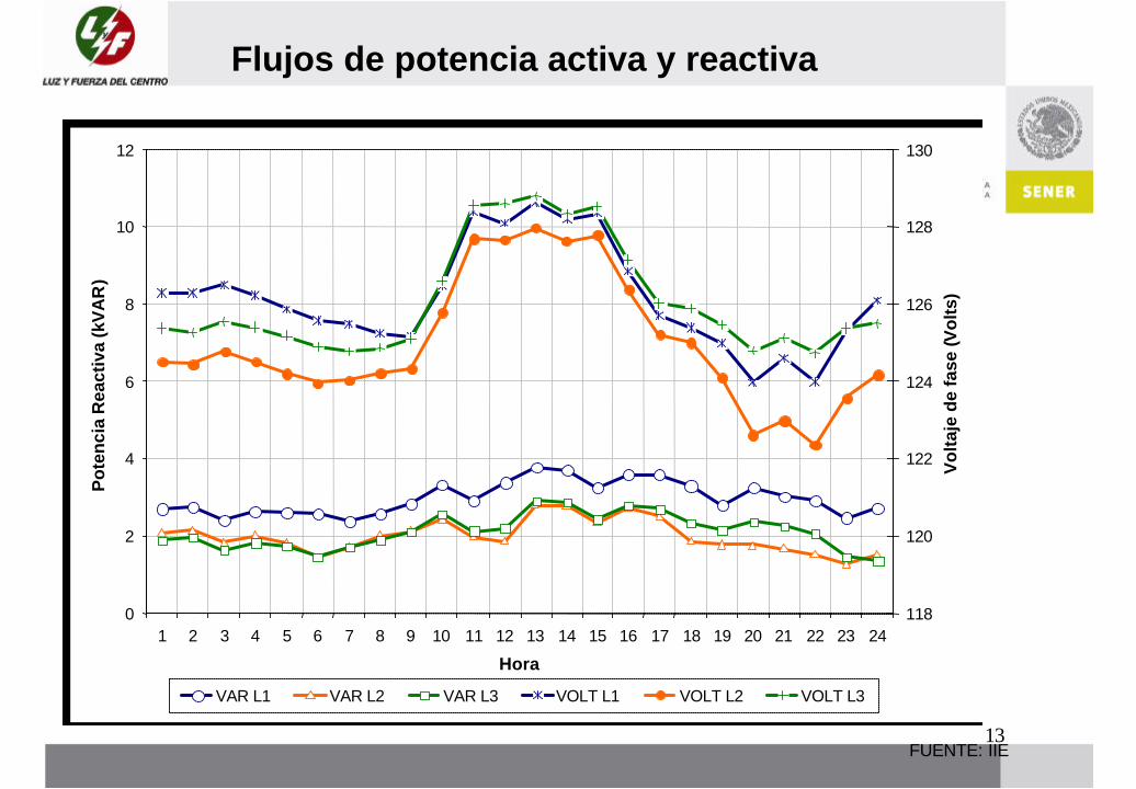
Flujos de potencia activa y reactiva
0
2
4
6
8
10
12
1 2 3 4 5 6 7 8 9 10 11 12 13 14 15 16 17 18 19 20 21 22 23 24
Hora
Po
ten
cia
Rea
ctiv
a (k
VA
R)
118
120
122
124
126
128
130
Vo
ltaj
e d
e fa
se (V
olt
s)
VAR L1 VAR L2 VAR L3 VOLT L1 VOLT L2 VOLT L3

14
RESUMEN DE DATOS GENERACION Y CONSUMO
• Producción SFVI es de 110.9 kWh/día.
• Consumo promedio en TGC es de 255.6 kWh/día (ver patrón de demanda).
• El 74.3% de la energía producida se consume directamente en TGC (91 kWh/día).
• El 25.7 % de la energía producida se vierte a la red eléctrica como excedente.
FUENTE: IIE

15
CONCLUSIONES
• Los resultados de operación desde el punto de vista de Luz y Fuerza del Centro son satisfactorios.
• Es necesario evaluar la cuestión de energía activa y reactiva.
• De igual forma la medición en el punto de intercambio debe hacerse con equipo que mida no solo de manera bidireccional, también debe medirse energía activa y reactiva.
16