INTERACTIVE SUPPORT SYSTEM USING HUMANOID ROBOT...
13
INTERACTIVE SUPPORT SYSTEM USING HUMANOID ROBOT FOR REHABILITATION OF GROSS MOTRICITY IN CHILDREN Piedad A. Semblantes, Pilatasig Marco Universidad de las Fuerzas Armadas ESPE, Sangolquí, Ecuador {pasemblantes,mapilatagsig}@espe.edu.ec Abstract.The present work is based on the implementation of a human-robot HRI inter- action system to support the sessions of gross motor rehabilitation in infants. The pro- posal is formed by a humanoid robot, which indicates the exercise of recovery that the child must imitate through movements of their extremities. At the same time, the mech- anism visually and auditorily motivates the child to ensure that the proposed exercises are carried out in a correct manner and thus assess the child's progress in therapy. A Field- Programmable Gate Array (FPGA) is used for the architecture of the system, which is responsible for controlling the robot as well as the validation algorithm and an auxiliary processor for the acquisition and processing of the information taken from the sensors in real time. For the validation of the exercises proposed in the therapy, the system proposes an algorithm based on classifiers. The algorithm is based on the comparison of patterns of the exercises performed by the humanoid in contrast to the acquired movements of inertial measurement sensors subject to the user. Keywords: Humanoid Robot, FPGA, DTW, Rehabilitation Systems, Gross Motricity, Children. Palabras clave: Robot humanoide, Matriz de puertas programables FPGA, Alineamiento temporal dinámico DTW, Sistemas de rehabilitación, Motricidad Gruesa, Niños. 1 Introduction According to the World Health Organization, (WHO) more than 1 billion people, or 15% of the world's population, have some kind of disability. In a more isolated case and depending on the type of limitation, children with disabilities usually have difficul- ties in carrying out daily activities, low educational performance, fewer economic op- portunities, and a higher rate of poverty in adulthood compared to healthy individuals. [1]. At the local level and according to records from the National Institute of Statistics and Census (INEC) of Ecuador, there is a growing demand in health centers in the area of physiotherapy, reporting in recent years a rate of four million treatments performed
Transcript of INTERACTIVE SUPPORT SYSTEM USING HUMANOID ROBOT...
INTERACTIVE SUPPORT SYSTEM USING
HUMANOID ROBOT FOR REHABILITATION OF
GROSS MOTRICITY IN CHILDREN
Piedad A. Semblantes, Pilatasig Marco
Universidad de las Fuerzas Armadas ESPE, Sangolquí, Ecuador
{pasemblantes,mapilatagsig}@espe.edu.ec
Abstract.The present work is based on the implementation of a human-robot HRI inter-
action system to support the sessions of gross motor rehabilitation in infants. The pro-
posal is formed by a humanoid robot, which indicates the exercise of recovery that the
child must imitate through movements of their extremities. At the same time, the mech-
anism visually and auditorily motivates the child to ensure that the proposed exercises
are carried out in a correct manner and thus assess the child's progress in therapy. A Field-
Programmable Gate Array (FPGA) is used for the architecture of the system, which is
responsible for controlling the robot as well as the validation algorithm and an auxiliary
processor for the acquisition and processing of the information taken from the sensors in
real time. For the validation of the exercises proposed in the therapy, the system proposes
an algorithm based on classifiers. The algorithm is based on the comparison of patterns
of the exercises performed by the humanoid in contrast to the acquired movements of
inertial measurement sensors subject to the user.
Keywords: Humanoid Robot, FPGA, DTW, Rehabilitation Systems, Gross
Motricity, Children.
Palabras clave: Robot humanoide, Matriz de puertas programables FPGA,
Alineamiento temporal dinámico DTW, Sistemas de rehabilitación, Motricidad Gruesa,
Niños.
1 Introduction
According to the World Health Organization, (WHO) more than 1 billion people, or
15% of the world's population, have some kind of disability. In a more isolated case
and depending on the type of limitation, children with disabilities usually have difficul-
ties in carrying out daily activities, low educational performance, fewer economic op-
portunities, and a higher rate of poverty in adulthood compared to healthy individuals.
[1]. At the local level and according to records from the National Institute of Statistics
and Census (INEC) of Ecuador, there is a growing demand in health centers in the area
of physiotherapy, reporting in recent years a rate of four million treatments performed
2
along the region [2][3]. The need for therapy in people who have suffered an injury or
illness causes a substantial increase in patients going to health centers, which requires
a considerable investment of time and money. Another kind of problem is the rehabili-
tation of children, due to the emotional state of their age. In these cases, traditional
rehabilitation sessions are often presented as unsuccessful and tedious therapies, be-
cause these processes tend to be routine and boring, causing children not accostum to
them and therefore slow down their recovery [4]. For this reason, the use of new meth-
ods based on emerging, innovative, and motivating technologies in the traditional re-
habilitation of children, promotes better results in their recovery. In this way, new meth-
ods to treat motor problems caused by cerebral palsy, brain injury or stroke have been
effective.Virtual interfaces have been developed, which can be manipulated by means
of innovative technological instruments such as gloves or robotic arms, thus forming
systems capable of providing support in the recovery of motor disabilities and attracting
the attention and curiosity of children [5] [6] [7].
On the other hand, robotics has been solving problems in different areas, both industrial
and consumer. In this context, robotic prototypes aimed to physical assistance in an
invasive way (prosthesis or exoskeletons) or social assistance in a non-invasive way
(robots for guidance, supervision, and diagnostic of therapy) merge engineering with
health areas [8]. In this context, the non-invasive robotic prototypes do not intend to
apply forces on the extremities of children, but rather emphasize attracting the attention
of the child, either by guiding or replicating the movements of the robot as he/she would
be with other children. In this case, [9], [10], and [11] propose humanoid robotic mech-
anisms to support the treatment of children with autism. In the same way, works dedi-
cated to treating motor problems have been developed. For example, [12] presents a
robot developed to rehabilitate the upper limbs by sequelae left by stroke (CVA). The
work presents a technique of non-invasive therapy, in which the robot does not come
into contact with the patient. The autonomy of the robot provides monitoring and re-
cording of activities, besides encouraging the patient of the exercise routine of their
recovery program. In conclusion, the programs of motor rehabilitation in children have
proven, through exhaustive studies, to be very useful in the recovery of their functions
and the improvement of their quality of life [13].
Therefore, this work proposes a novel alternative which provides support to the te-
dious rehabilitation sessions for minors, in order to present a game environment where
the patient interacts physically with a humanoid robot, which motivates and guides the
child in the execution of the therapy. Through a series of movements which the robot
executes as guide exercises, it is intended to rehabilitate and strengthen the locomotor
system coordinated by the cerebral cortex and secondary structures that modulate it, the
same ones that have been affected by injuries left, either by a brain accident, illness or
damage by physical activities. To achieve this, the proposed system carries out a vali-
dation algorithm for the exercises performed by the child, taking into account the tech-
niques of pattern identification given by the DTW algorithm (dynamic temporal align-
ment). The purpose of this algorithm is to measure the homogeneity of the sequences
obtained from a set of electronic armbands arranged in such a way in the injured ex-
tremities of the minor (3 SPACE SENSOR) versus the pre-recorded pattern sequence
3
in the humanoid robot (BIOLOID ROBOT). Finally, several experimental results are
shown to validate the proposed system.
2 System Structure
The developed system is based on a human-robot interaction (HRI) architecture, where
the patient interacts directly with a humanoid robot. The rehabilitation proposal is based
on the comparison between the therapeutic movements made by the robot versus the
movements replicated by the patient. These activities are detected through the use of
inertial measure sensors, which are located on the affected limbs which are to be reha-
bilitated in the child. On the other hand, the guiding movements which the robot exe-
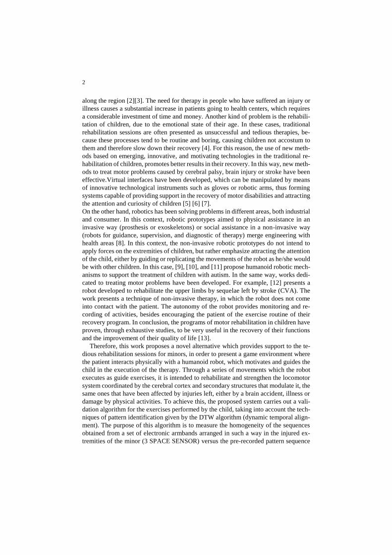
cutes are achieved through control criteria based on inverse kinematics. The Fig. 1
shows the scheme of the developed system. The proposal includes a rehabilitation strat-
egy that can be used both in upper and lower extremities, where the progress of the
therapy will be assessed by degrees of difficulty (moderate and mild) based on the ini-
tial medical diagnosis. Additionally, the system provides feedback through audio out-
puts which motivate and guide the child during the execution of the treatment.
Fig. 1. Structure of the System for Thick Motricity Rehabilitation
The interaction of the patient with the rehabilitation robotic system is based on the in-
formation acquired from the inertial measure sensors (IMU). On the other hand, the
movements of the robot are in function to the previous diagnosis of the therapist, who
evaluates the child and designates the exercises that must be carried out in the therapy.
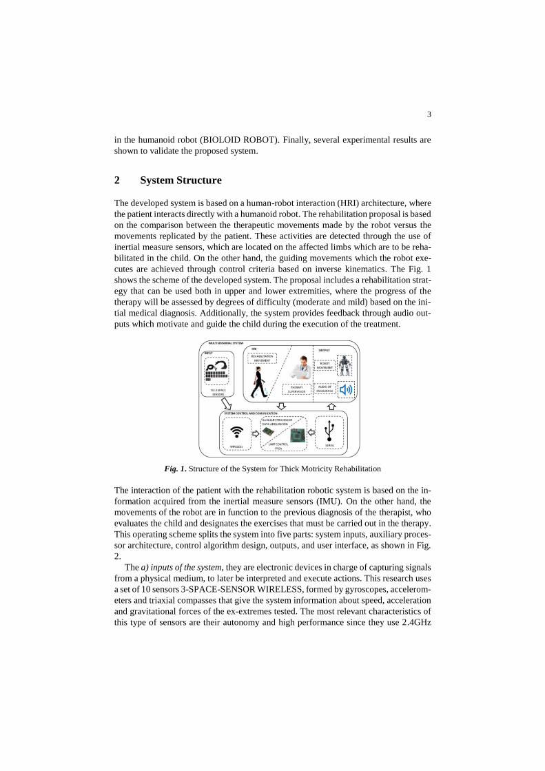
This operating scheme splits the system into five parts: system inputs, auxiliary proces-
sor architecture, control algorithm design, outputs, and user interface, as shown in Fig.
2.
The a) inputs of the system, they are electronic devices in charge of capturing signals
from a physical medium, to later be interpreted and execute actions. This research uses
a set of 10 sensors 3-SPACE-SENSOR WIRELESS, formed by gyroscopes, accelerom-
eters and triaxial compasses that give the system information about speed, acceleration
and gravitational forces of the ex-extremes tested. The most relevant characteristics of
this type of sensors are their autonomy and high performance since they use 2.4GHz
4
wireless communication, providing the system with low latency and high precision at
the time of data capture in real time.
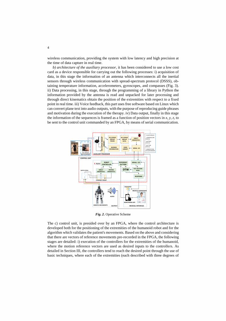
b) architecture of the auxiliary processor, it has been considered to use a low cost
card as a device responsible for carrying out the following processes: i) acquisition of
data, in this stage the information of an antenna which interconnects all the inertial
sensors through wireless communication with spread-spectrum protocol (DSSS), ob-
taining temperature information, accelerometers, gyroscopes, and compasses (Fig. 3).
ii) Data processing, in this stage, through the programming of a library in Python the
information provided by the antenna is read and unpacked for later processing and
through direct kinematics obtain the position of the extremities with respect to a fixed
point in real time. iii) Voice feedback, this part uses free software based on Linux which
can convert plane text into audio outputs, with the purpose of reproducing guide phrases
and motivation during the execution of the therapy. iv) Data output, finally in this stage
the information of the sequences is framed as a function of position vectors in x, y, z, to
be sent to the control unit commanded by an FPGA, by means of serial communication.
- EULER ANGLES
- TEMPERATURE STATUS
- BATTERY STATUS
- BUTTON STATUS
- ORIENTATION AS QUATERNION
INVOKED INFORMATION
YEI 3 SPACE MOCAP FRAME
YEI 3 SPACE MOCAP
DATA
VOICE LIBRARY
DIRECT KINEMATICS
SERIAL I/O
AUXILIARY PROCESSOR
YE
I 3 S
PA
CE
MO
CA
P
LIB
RA
RY
reference pattern
SERIAL I/O
TEST PATTERN READ
REFERENCE PATTERN
DTWDIRECT KINEMATICS
INVERSE KINEMATICS
ROBOT CONTROLLER
RX
TX
DYNAMIXEL LIBRARY
RESPONSE
CONTROL UNIT
OUTPUT MEDICAL INTERFACE
AUDIO
ROBOTIC MOVEMENTS
DATA BASE
MEDICAL SUPERVISION
MONITORING APP
SWITCH SERIAL
``
YEI 3 SPACE
MOCAP SENSOR
INPUT
Fig. 2. Operative Scheme
The c) control unit, is presided over by an FPGA, where the control architecture is
developed both for the positioning of the extremities of the humanoid robot and for the
algorithm which validates the patient's movements. Based on the above and considering
that there are vectors of reference movements pre-recorded in the FPGA, the following
stages are detailed: i) execution of the controllers for the extremities of the humanoid,
where the motion reference vectors are used as desired inputs to the controllers. As
detailed in Section III, the controllers tend to reach the desired point through the use of
basic techniques, where each of the extremities (each described with three degrees of
5
freedom) must generate repeatable movements for the child. The FPGA includes inter-
nal libraries that command the chain of intelligent servomotors, as well as read posi-
tioning information to validate the execution and provide errors that will be corrected
by the control strategy. On the other hand, the reference vectors are used by the DTW
algorithm (an algorithm for each extremity) with the objective of ii) compare them with
the vectors generated by the patient, after a session is finished or when the application
has reached a timeout. Finally, iii) the FPGA can reply to serial communication com-
mands, with the purpose of providing responses of the comparison of patterns, validat-
ing or not the successful execution of the session. Likewise, these responses are sent
forcibly to the auxiliary preprocessor in order to generate sonorous commands that en-
courage the patient.
BIA
S, S
CA
LE, N
OR
MA
LIZA
TIO
N,
ERR
OR
CO
MP
ENSA
TIO
N
KALMAN FILTER
FINAL ORIENTATION
USB 2.0INTERFACE
NON-VOLATILE CALIBRATION & PERFORMANCE SETINGS
USB MOUSE & JOYSTICK EMULATION
2.4 Ghz DSSSWIRELESS INTERFACE
PROCESSOR
LIPO BATTERY WIRELESS MODULE & ANTENA
USB 2.0HOST SYSTEM
TSS WIRELESS 2.4 Ghz DSSS
TEMPERATURE SENSOR
3-AXIS ACCELEROMETER
3-AXIS RATE GYRO
3-AXISCOMPASS
RASPBERRY PI
Fig. 3. Acquisition of data with 3-SPACE sensors
The elements used as d) outputs for this system are described below: i) the humanoid
robot reproduces a series of movements by positioning its dynamixel motors, these
movements are generated by the FPGA and are in function of the initial requirements
of the therapist when evaluating the patient. ii) Audio, it is used to guide and to encour-
age the patient while it develops the exercises of rehabilitation, these phrases are gen-
erated by the auxiliary processor and reproduced by a speaker located on the robot hu-
manoid.
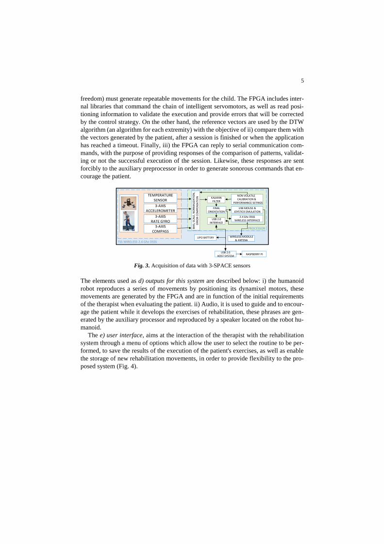
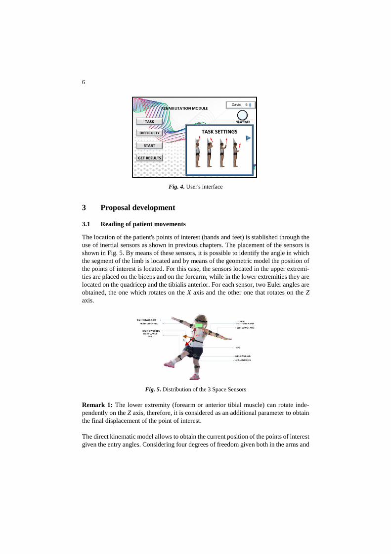
The e) user interface, aims at the interaction of the therapist with the rehabilitation
system through a menu of options which allow the user to select the routine to be per-
formed, to save the results of the execution of the patient's exercises, as well as enable
the storage of new rehabilitation movements, in order to provide flexibility to the pro-
posed system (Fig. 4).
6
PUSH
NEW TASK
TASK SETTINGS
David, 6
Fig. 4. User's interface
3 Proposal development
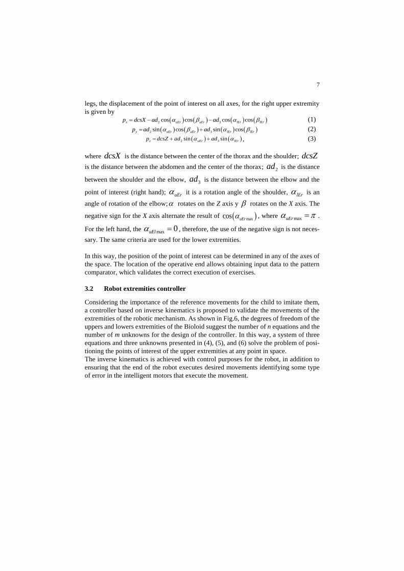
3.1 Reading of patient movements
The location of the patient's points of interest (hands and feet) is stablished through the
use of inertial sensors as shown in previous chapters. The placement of the sensors is
shown in Fig. 5. By means of these sensors, it is possible to identify the angle in which
the segment of the limb is located and by means of the geometric model the position of
the points of interest is located. For this case, the sensors located in the upper extremi-
ties are placed on the biceps and on the forearm; while in the lower extremities they are
located on the quadricep and the tibialis anterior. For each sensor, two Euler angles are
obtained, the one which rotates on the X axis and the other one that rotates on the Z
axis.
Fig. 5. Distribution of the 3 Space Sensors
Remark 1: The lower extremity (forearm or anterior tibial muscle) can rotate inde-
pendently on the Z axis, therefore, it is considered as an additional parameter to obtain
the final displacement of the point of interest.
The direct kinematic model allows to obtain the current position of the points of interest
given the entry angles. Considering four degrees of freedom given both in the arms and
Z
Y
X
7
legs, the displacement of the point of interest on all axes, for the right upper extremity
is given by
2 3cos cos cos cosx uEr uEr lEr lErp dcsX ad ad (1)
2 3sin cos sin cosy uEr uEr lEr lErp ad ad (2)
2 3sin sinz uEr lErp dcsZ ad ad , (3)
where dcsX is the distance between the center of the thorax and the shoulder; dcsZ
is the distance between the abdomen and the center of the thorax; 2ad is the distance
between the shoulder and the elbow, 3ad is the distance between the elbow and the
point of interest (right hand); uEr it is a rotation angle of the shoulder, lEr is an
angle of rotation of the elbow; rotates on the Z axis y rotates on the X axis. The
negative sign for the X axis alternate the result of maxcos uEr , where maxuEr .
For the left hand, the max 0uEl , therefore, the use of the negative sign is not neces-
sary. The same criteria are used for the lower extremities.
In this way, the position of the point of interest can be determined in any of the axes of
the space. The location of the operative end allows obtaining input data to the pattern
comparator, which validates the correct execution of exercises.
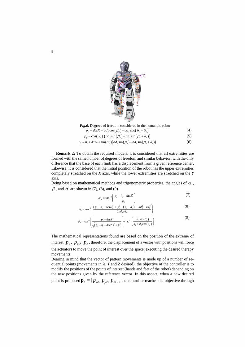
3.2 Robot extremities controller
Considering the importance of the reference movements for the child to imitate them,
a controller based on inverse kinematics is proposed to validate the movements of the
extremities of the robotic mechanism. As shown in Fig.6, the degrees of freedom of the
uppers and lowers extremities of the Bioloid suggest the number of n equations and the
number of m unknowns for the design of the controller. In this way, a system of three
equations and three unknowns presented in (4), (5), and (6) solve the problem of posi-
tioning the points of interest of the upper extremities at any point in space.
The inverse kinematics is achieved with control purposes for the robot, in addition to
ensuring that the end of the robot executes desired movements identifying some type
of error in the intelligent motors that execute the movement.
8
Fig.6. Degrees of freedom considered in the humanoid robot
2 3cos cosx a a ap dcsX ad ad (4)
2 3cos . sin siny a a a ap ad ad (5)
2 3sin sin sinz c a a a ap h dcsZ ad ad (6)
Remark 2: To obtain the required models, it is considered that all extremities are
formed with the same number of degrees of freedom and similar behavior, with the only
difference that the base of each limb has a displacement from a given reference center.
Likewise, it is considered that the initial position of the robot has the upper extremities
completely stretched on the X axis, while the lower extremities are stretched on the Y
axis.
Being based on mathematical methods and trigonometric properties, the angles of ,
, and are shown in (7), (8), and (9).
1tan z ca
y
p h dcsZ
p
(7)
2 22 2 2
2 31
2 3
cos2
z c y x x
a
p h dcsZ p p d ad ad
ad ad
(8)
31 1
2 22 3
sintan tan
cos
axa
az c y
dp dscX
d dp h dscZ p
(9)
The mathematical representations found are based on the position of the extreme of
interest xp , yp y zp , therefore, the displacement of a vector with positions will force
the actuators to move the point of interest over the space, executing the desired therapy
movements.
Bearing in mind that the vector of pattern movements is made up of a number of se-
quential points (movements in X, Y and Z desired), the objective of the controller is to
modify the positions of the points of interest (hands and feet of the robot) depending on
the new positions given by the reference vector. In this aspect, when a new desired
point is proposed [ , , ]xd yd zdp p pdp , the controller reaches the objective through
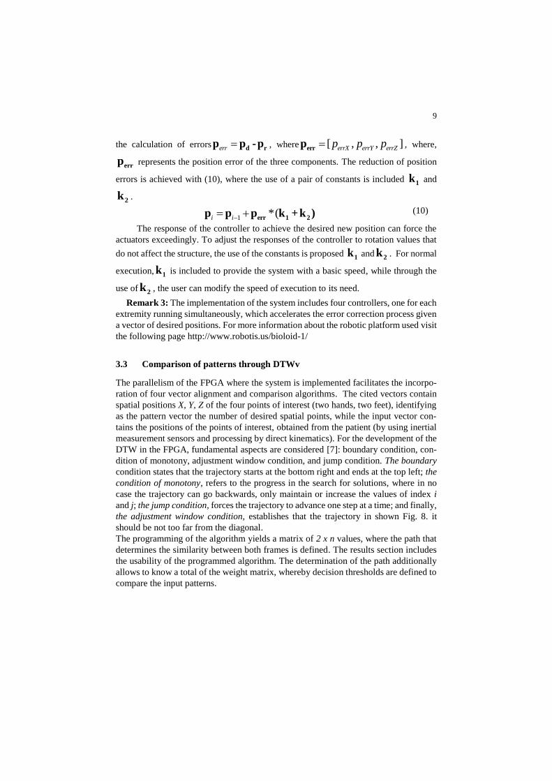
9
the calculation of errors err d rp p -p , where [ , , ]errX errY errZp p p
errp , where,
errp represents the position error of the three components. The reduction of position
errors is achieved with (10), where the use of a pair of constants is included 1k and
2k .
1 *(i i err 1 2
p p p k +k ) (10)
The response of the controller to achieve the desired new position can force the
actuators exceedingly. To adjust the responses of the controller to rotation values that
do not affect the structure, the use of the constants is proposed 1k and 2k . For normal
execution, 1k is included to provide the system with a basic speed, while through the
use of 2k , the user can modify the speed of execution to its need.
Remark 3: The implementation of the system includes four controllers, one for each
extremity running simultaneously, which accelerates the error correction process given
a vector of desired positions. For more information about the robotic platform used visit
the following page http://www.robotis.us/bioloid-1/
3.3 Comparison of patterns through DTWv
The parallelism of the FPGA where the system is implemented facilitates the incorpo-
ration of four vector alignment and comparison algorithms. The cited vectors contain
spatial positions X, Y, Z of the four points of interest (two hands, two feet), identifying
as the pattern vector the number of desired spatial points, while the input vector con-
tains the positions of the points of interest, obtained from the patient (by using inertial
measurement sensors and processing by direct kinematics). For the development of the
DTW in the FPGA, fundamental aspects are considered [7]: boundary condition, con-
dition of monotony, adjustment window condition, and jump condition. The boundary
condition states that the trajectory starts at the bottom right and ends at the top left; the
condition of monotony, refers to the progress in the search for solutions, where in no
case the trajectory can go backwards, only maintain or increase the values of index i
and j; the jump condition, forces the trajectory to advance one step at a time; and finally,
the adjustment window condition, establishes that the trajectory in shown Fig. 8. it
should be not too far from the diagonal.
The programming of the algorithm yields a matrix of 2 x n values, where the path that
determines the similarity between both frames is defined. The results section includes
the usability of the programmed algorithm. The determination of the path additionally
allows to know a total of the weight matrix, whereby decision thresholds are defined to
compare the input patterns.
10
4 Results
The results of the proposal are split into three parts, starting with the test of data acqui-
sition on the patient's movements through direct kinematics and the use of inertial sen-
sors. On the other hand, the second group of results presents the correct execution of
reference movements by the robotic mechanism, validating the proposed controller. Fi-
nally, the alignment of the movement vectors is presented to determine the coincidences
between the movements executed by the robot (reference movements) and the move-
ments of the child.
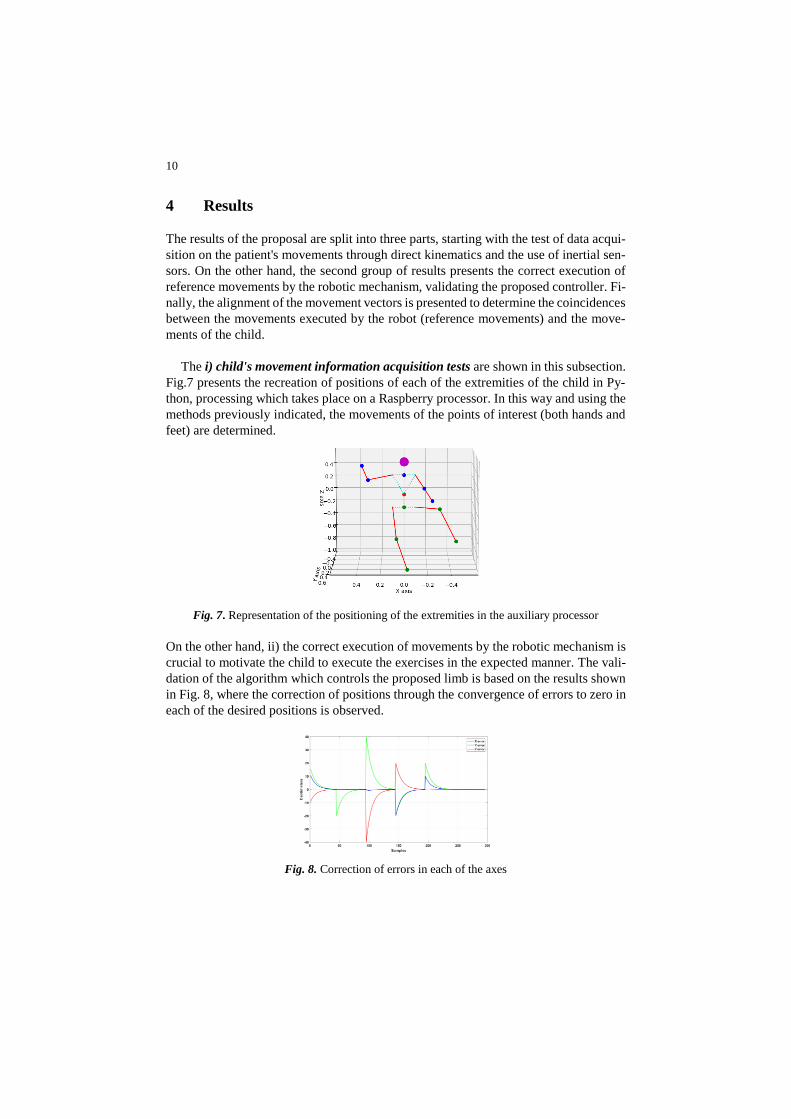
The i) child's movement information acquisition tests are shown in this subsection.
Fig.7 presents the recreation of positions of each of the extremities of the child in Py-
thon, processing which takes place on a Raspberry processor. In this way and using the
methods previously indicated, the movements of the points of interest (both hands and
feet) are determined.
Fig. 7. Representation of the positioning of the extremities in the auxiliary processor
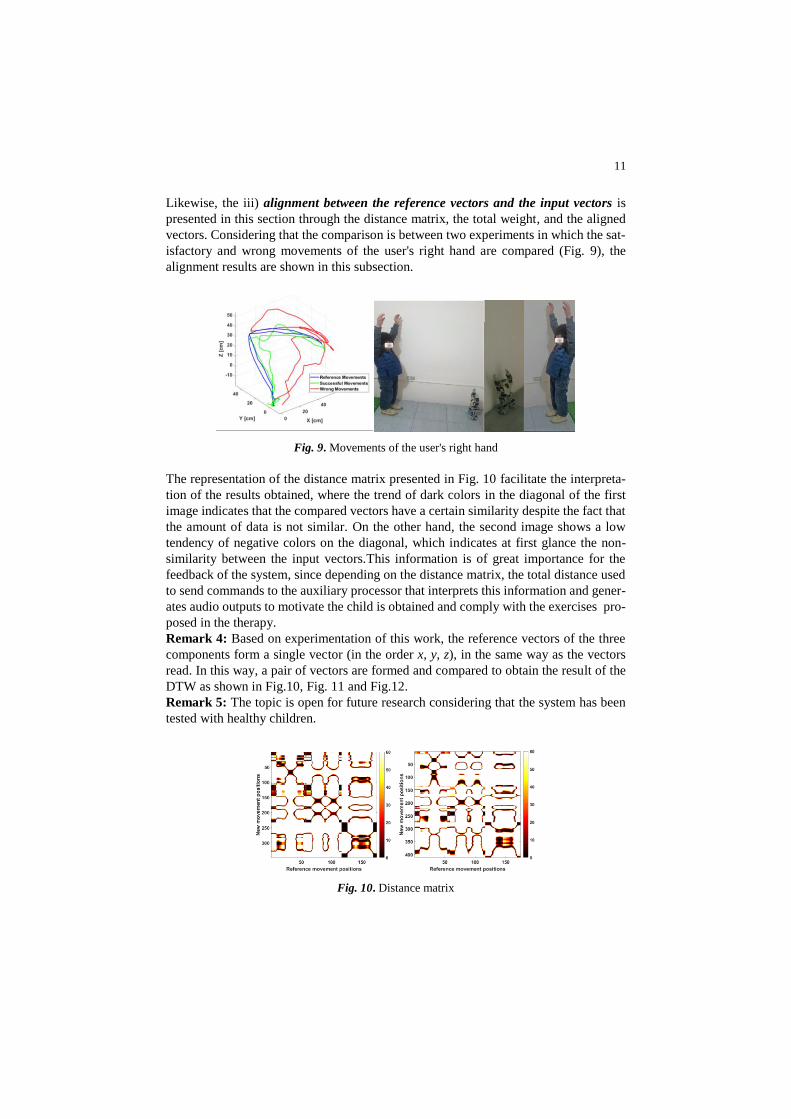
On the other hand, ii) the correct execution of movements by the robotic mechanism is
crucial to motivate the child to execute the exercises in the expected manner. The vali-
dation of the algorithm which controls the proposed limb is based on the results shown
in Fig. 8, where the correction of positions through the convergence of errors to zero in
each of the desired positions is observed.
Fig. 8. Correction of errors in each of the axes
11
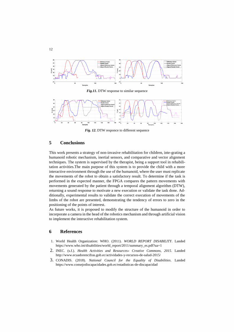
Likewise, the iii) alignment between the reference vectors and the input vectors is
presented in this section through the distance matrix, the total weight, and the aligned
vectors. Considering that the comparison is between two experiments in which the sat-
isfactory and wrong movements of the user's right hand are compared (Fig. 9), the
alignment results are shown in this subsection.
Fig. 9. Movements of the user's right hand
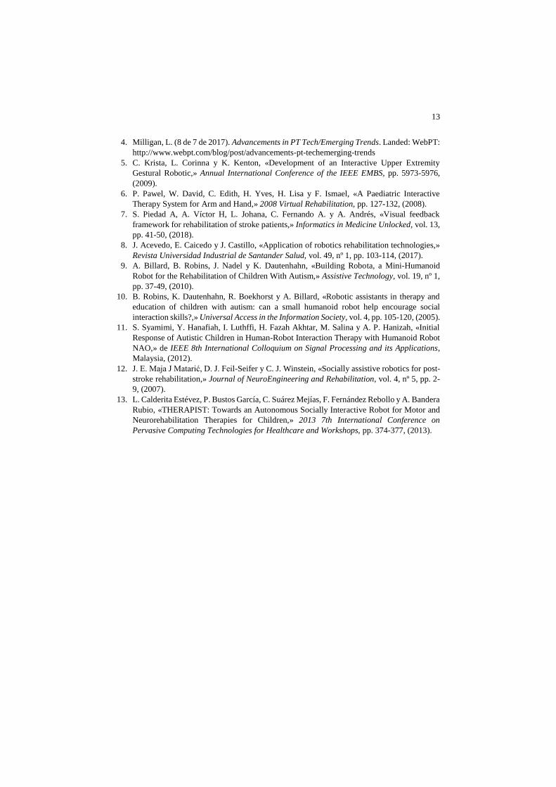
The representation of the distance matrix presented in Fig. 10 facilitate the interpreta-
tion of the results obtained, where the trend of dark colors in the diagonal of the first
image indicates that the compared vectors have a certain similarity despite the fact that
the amount of data is not similar. On the other hand, the second image shows a low
tendency of negative colors on the diagonal, which indicates at first glance the non-
similarity between the input vectors.This information is of great importance for the
feedback of the system, since depending on the distance matrix, the total distance used
to send commands to the auxiliary processor that interprets this information and gener-
ates audio outputs to motivate the child is obtained and comply with the exercises pro-
posed in the therapy.
Remark 4: Based on experimentation of this work, the reference vectors of the three
components form a single vector (in the order x, y, z), in the same way as the vectors
read. In this way, a pair of vectors are formed and compared to obtain the result of the
DTW as shown in Fig.10, Fig. 11 and Fig.12.
Remark 5: The topic is open for future research considering that the system has been
tested with healthy children.
Fig. 10. Distance matrix
12
Fig.11. DTW response to similar sequence
Fig. 12. DTW responce to different sequence
5 Conclusions
This work presents a strategy of non-invasive rehabilitation for children, inte-grating a
humanoid robotic mechanism, inertial sensors, and comparative and vector alignment
techniques. The system is supervised by the therapist, being a support tool in rehabili-
tation activities.The main purpose of this system is to provide the child with a more
interactive environment through the use of the humanoid, where the user must replicate
the movements of the robot to obtain a satisfactory result. To determine if the task is
performed in the expected manner, the FPGA compares the pattern movements with
movements generated by the patient through a temporal alignment algorithm (DTW),
returning a sound response to motivate a new execution or validate the task done. Ad-
ditionally, experimental results to validate the correct execution of movements of the
limbs of the robot are presented, demonstrating the tendency of errors to zero in the
positioning of the points of interest.
As future works, it is proposed to modify the structure of the humanoid in order to
incorporate a camera in the head of the robotics mechanism and through artificial vision
to implement the interactive rehabilitation system.
6 References
1. World Health Organization: WHO. (2011). WORLD REPORT DISABILITY. Landed
https://www.who.int/disabilities/world_report/2011/summary_es.pdf?ua=1
2. INEC. (s.f.). Health Activities and Resources» Creative Commons, 2015. Landed
http://www.ecuadorencifras.gob.ec/actividades-y-recursos-de-salud-2015/ 3. CONADIS. (2018). National Council for the Equality of Disabilities. Landed
https://www.consejodiscapacidades.gob.ec/estadisticas-de-discapacidad
13
4. Milligan, L. (8 de 7 de 2017). Advancements in PT Tech/Emerging Trends. Landed: WebPT:
http://www.webpt.com/blog/post/advancements-pt-techemerging-trends
5. C. Krista, L. Corinna y K. Kenton, «Development of an Interactive Upper Extremity
Gestural Robotic,» Annual International Conference of the IEEE EMBS, pp. 5973-5976,
(2009).
6. P. Pawel, W. David, C. Edith, H. Yves, H. Lisa y F. Ismael, «A Paediatric Interactive
Therapy System for Arm and Hand,» 2008 Virtual Rehabilitation, pp. 127-132, (2008).
7. S. Piedad A, A. Víctor H, L. Johana, C. Fernando A. y A. Andrés, «Visual feedback
framework for rehabilitation of stroke patients,» Informatics in Medicine Unlocked, vol. 13,
pp. 41-50, (2018).
8. J. Acevedo, E. Caicedo y J. Castillo, «Application of robotics rehabilitation technologies,»
Revista Universidad Industrial de Santander Salud, vol. 49, nº 1, pp. 103-114, (2017).
9. A. Billard, B. Robins, J. Nadel y K. Dautenhahn, «Building Robota, a Mini-Humanoid
Robot for the Rehabilitation of Children With Autism,» Assistive Technology, vol. 19, nº 1,
pp. 37-49, (2010).
10. B. Robins, K. Dautenhahn, R. Boekhorst y A. Billard, «Robotic assistants in therapy and
education of children with autism: can a small humanoid robot help encourage social
interaction skills?,» Universal Access in the Information Society, vol. 4, pp. 105-120, (2005).
11. S. Syamimi, Y. Hanafiah, I. Luthffi, H. Fazah Akhtar, M. Salina y A. P. Hanizah, «Initial
Response of Autistic Children in Human-Robot Interaction Therapy with Humanoid Robot
NAO,» de IEEE 8th International Colloquium on Signal Processing and its Applications,
Malaysia, (2012).
12. J. E. Maja J Matarić, D. J. Feil-Seifer y C. J. Winstein, «Socially assistive robotics for post-
stroke rehabilitation,» Journal of NeuroEngineering and Rehabilitation, vol. 4, nº 5, pp. 2-
9, (2007).
13. L. Calderita Estévez, P. Bustos García, C. Suárez Mejías, F. Fernández Rebollo y A. Bandera
Rubio, «THERAPIST: Towards an Autonomous Socially Interactive Robot for Motor and
Neurorehabilitation Therapies for Children,» 2013 7th International Conference on
Pervasive Computing Technologies for Healthcare and Workshops, pp. 374-377, (2013).