Intelligent valve control and monitoring - Val · PDF fileIntelligent valve control and...
14
Intelligent valve control and monitoring DVC-PL-001-03 - Intelligent Valve Controller
-
Upload
hoangxuyen -
Category
Documents
-
view
224 -
download
2
Transcript of Intelligent valve control and monitoring - Val · PDF fileIntelligent valve control and...

Intelligent valve control and monitoring
DVC-PL-001-03 - Intelligent Valve Controller

Intelligent Valve Controller
1
Val Controls® A/S Intelligent valve control based on the latest know-how concerning digital technology for advanced valve control, monitoring and testing suited for pneumatic and hydraulic actuators. Our key task is to assist valve and actuator manufactures in finding the optimal solution for control, monitoring or testing of their products. We discover the best solutions for hazardous areas and harsh environments combined with cost reduction potentials. Index Introduction .................................................................................................................................... 2
Models ............................................................................................................................................ 3
Application...................................................................................................................................... 4
SIL .................................................................................................................................................. 5
Configuration .................................................................................................................................. 6
Diagnostic ...................................................................................................................................... 7
Power unit controller ...................................................................................................................... 8
Hardware features ......................................................................................................................... 9
Software features ......................................................................................................................... 10
Model selector .............................................................................................................................. 11
Intelligent Valve Controller
2
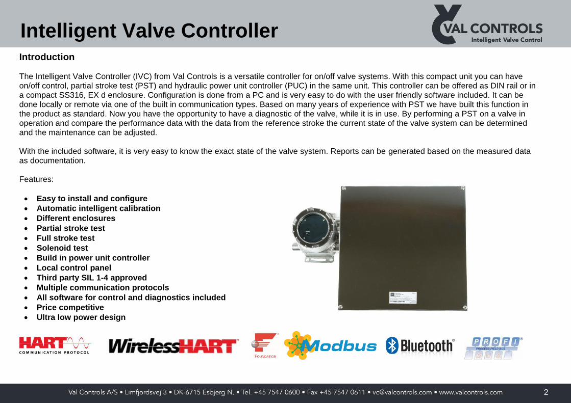
Introduction The Intelligent Valve Controller (IVC) from Val Controls is a versatile controller for on/off valve systems. With this compact unit you can have on/off control, partial stroke test (PST) and hydraulic power unit controller (PUC) in the same unit. This controller can be offered as DIN rail or in a compact SS316, EX d enclosure. Configuration is done from a PC and is very easy to do with the user friendly software included. It can be done locally or remote via one of the built in communication types. Based on many years of experience with PST we have built this function in the product as standard. Now you have the opportunity to have a diagnostic of the valve, while it is in use. By performing a PST on a valve in operation and compare the performance data with the data from the reference stroke the current state of the valve system can be determined and the maintenance can be adjusted. With the included software, it is very easy to know the exact state of the valve system. Reports can be generated based on the measured data as documentation. Features:
Easy to install and configure
Automatic intelligent calibration
Different enclosures
Partial stroke test
Full stroke test
Solenoid test
Build in power unit controller
Local control panel
Third party SIL 1-4 approved
Multiple communication protocols
All software for control and diagnostics included
Price competitive
Ultra low power design

Intelligent Valve Controller
3
Models The Val Controls Intelligent Valve Controller comes in different models. Each model can be configured after customer requirements.
Flameproof This Flameproof is an IVC with a build in non-contact transmitter. It can be used for controlling and diagnosing on/off valve systems. The switchbox model is designed around a SS316 flameproof enclosure with Direct mounting. As an option limit switches can be mounted in the enclosure.
IVC24-F
Advanced and advanced flameproof This model is for customers with very high demands for performance and connection possibilities. This unit is very flexible and can be configured to almost any customers needs and can be easily expanded, e.g. with a backup battery or other advanced features. The Advanced Flameproof model is designed around a SS316 flameproof enclosure. It offers the same features as the Advanced model, but is very compact in the stainless steel enclosure.
IVC24-A
IVC24-AF

Intelligent Valve Controller
4
Application
The IVC can be connected to a valve system as shown on the figure to the right. This setup allows the IVC to de-energize the solenoid valve, but can never interrupt an ESD. The “Operational” and “Fail position” buttons on the local control panel is for controlling the valve. The “Start test” button is for starting a PST and then the “Test in progress” lamp will turn on. After the test the result is shown to the user by the “Pass” and “Fail” lamp. Further analysis of the measured data is then carried out on a PC.
24 VDC ESD
Position sensor
Solenoid valve
Communication
T
Actuator
Valve
PASS
FAIL
TEST IN PROGRESS
ESD SOV
Local control panel
OPERATIONAL
FAIL POSITION
START TEST

Intelligent Valve Controller
5
SIL
The IVC is designed to be used in safety instrument systems for partial stroke testing of emergency shut-down valves with no negative impact on the safety function. The IVC does not adversely affect the execution of the safety function. There exist two types of SIL circuits, which both are optional.
IVC with SIL expansion card This solution makes it easy to retrofit the IVC as no extra wiring is required. The unit is powered through the ESD line, which means that the IVC will lose power during an ESD.
Emergency shutdown controller
Emergencyshutdown
solenoid operated valve
Intelligent Valve Controller
ESD SOV (+)
ESD SOV (-)
ESD 24 VDC (+)
ESD 24 VDC (-)
24 VDC (+)
24 VDC (-)
IVC with SIL expansion card + extra 24 VDC When using an external power supply then the IVC can measure performance data in case of an ESD. This is beneficial as data from ESDs can be used to verify the status of the valve system.
Emergency shutdown controller
Emergencyshutdown
solenoid operated valve
Power supply
Intelligent Valve Controller
ESD SOV (+)
ESD SOV (-)
ESD 24 VDC (+)
ESD 24 VDC (-)
24 VDC (+)
24 VDC (-)

Intelligent Valve Controller
6
Configuration
Setup of the unit is done from a PC by Val Controls – Configurator software. The digital in- and outputs connected to the local control panel can be set and easily adapted to the current system. All settings and limits for the tests can be set, such as valve travel for the PST.

Intelligent Valve Controller
7
Diagnostic
A partial stroke test can be initiated from the local control panel or through a communication protocol. The unit stores the measurements from the last 10 tests of each type along with the data from the references. These data can be retrieved through a communication protocol to the control room for analysis and report generation. The reference partial stroke test is used to auto generate limits for errors and warning. These can be changed in the configuration.

Intelligent Valve Controller
8
Power unit controller
The power unit controller can control a hydraulic pump to keep the pressure in the system within a specified range by monitoring the pressure in the system. Furthermore is the temperature of the oil, the level in the tank, and a safety relay monitored as safety functions to avoid damaging the system. The signals are used to determine when to turn the pump off, no matter what the pressure is. All inputs are optional.
Power output
Digital output (24VDC)
Safety timer Pressure input
High limit
Low limit
4-20 mA input
Switches (NO/NC) Level input
Low limit alarm
4-20 mA input
Switches (NO/NC)
Safety relay
Digital input (NO/NC)
Alarm Temperature input
High limit alarm
Low limit alarm
4-20 mA input
Switches (NO/NC) Control modes
Auto
Always on
Always off
Manual
Power supply
Communication
Hydraulic system
Pump
Pressure
Level
Temperature
ReturnSupply

Intelligent Valve Controller
9
Hardware features Model A – Advanced AF – Advanced Flameproof F – Flameproof Analogue input
4-20mA sensors ●/5 ●/1
Position feedback
- Position sensor - 3-wire potentiometer ●
- Position loop - 4-20mA ● ●
Analogue output
Advanced 4-20mA transmitter loop ● ●
Transmitter (Non-contact) ●
Digital inputs
Digital inputs internal powered ●/4 ●/3
Power supply to unit 24VDC 24VDC
Digital outputs
Digital outputs ●/6 ●/3
Max power consumption per output 48W @24VDC 48W @24VDC
Limit switches ○
Digital outputs – Emergency Shutdown Controller (SIL)
Digital outputs ●/2 ●/1
Monitoring of power consumption ● ●
ESD detection ● ●
Max power consumption per output 48W @24VDC 48W @24VDC
Watch
Internal watch with battery backup ○ ●
Communication
HART v.7 ○ ○ Modbus RTU – RS-485 ○ ○ Foundation Fieldbus H1 ○ ○ Profibus DP/DPV1 Other communication protocols on request ○ ○
Wireless communication Bluetooth V2.0 ○ ○ Wireless HART ○ ○
Design
Temperature -40 to 85˚C -40 to 85˚C -20 to 55˚C
IP IP20 IP66/68 IP66/67
DIN-rail mounting EN 50022 ●
Flameproof - Ex-d IIC T6 – ATEX and IECEx ●
Flameproof - Ex-d IIC T6 – ATEX and IECEx with direct mounting ●
Limit switch
SPDT V3 Mechanical - 10 A @ 125 / 250 VAC, 0.5 A @ 125 VDC ○
SPDT Reed Type Proximity - Volts 500 VAC/ DC (Max.), Current 3 A (Max.), ○
V3 Namur Type Inductive Proximity - On I <1mA, Off I >3mA, 8 VDC Nominal ○
Standard = ● Extra option = ○

Intelligent Valve Controller
10
Software features
The IVC range comes with the following software functions. Model A – Advanced AF – Advanced Flameproof F – Flameproof Functions
Automatic intelligent calibration ● ●
Manual calibration ● ●
Valve action – Direct/reverse ● ●
Spring Return or Double Acting actuator ● ●
Performance data, partial stoke test, full stroke test and solenoid test ● ● Installation, control, monitoring and diagnostic using IVC PC suite ● ● Manual control of valves and actuator ● ●
Error handling ● ●
Local control panel functions ● ●
- Manuel open/close – Operational/fail position ● ●
- Initiate test ● ●
- Test in progress indicator ● ●
- Open/Close indicator ● ●
- Pass/fail indicator ● ●
Advanced logging of performance and events ● ●
Power unit control
Output for starting pump unit ●
Motor safety relay ●
Max running time ●
Pressure monitoring
- 4-20mA pressure transmitter ●
- 2 x pressure switches – for on/off function ●
Level monitoring - low
- 4-20mA level transmitter ●
- Level switch ●
Temperature monitoring – high/low
- 4-20mA temperature transmitter ●
- Temperature switch ●
Standard = ● Extra option = ○

Intelligent Valve Controller
11
Model selector The selector can be used for selecting the correct part number needed. Product name Type Communication 1 Communication 2 Expansion card 1 Expansion card 2 Expansion card 3 - Software features - Limit switch
IVC24 - A - B1 B2 C1 C2 C3 D E
A Type
F Flameproof ○ ○ ● ● ○
A Advanced ○ ○ ● ○
AF Advanced Flameproof ○ ○ ● ○
AFL Advanced Flameproof - Local Control Panel
○ ○ ● ○
B1 Communication 1
0 None
2 HART – Transmitter loop
3 Modbus RTU
4 Foundation Fieldbus H1
5 Wireless HART
7 Foundation Fieldbus H1 + 4-20mA transmitter loop
8 Profibus DP
9 Profibus DPV1
B2 Communication 2
0 None
1 Bluetooth
C1 Expansion card 1
1 Watch with battery
C2 Expansion card 2
0 None
3 Emergency Shutdown Controller (SIL)
4 Emergency Shutdown Controller (SIL) + extra 24VDC power supply
C3 Expansion card 3
0 None
D Software features
- None
E Limit switch
1 2 x SPDT V3 Mechanical
2 2 x SPDT Reed Type Proximity
3 2 x V3 Namur Type Inductive Proximity
Standard = ● Extra option = ○
Model example: Advanced version with Modbus and emergency shutdown controller – IVC24-A-30130

Intelligent Valve Controller
12
Model selector – IVC24-F The selector can be used for selecting the correct part number needed. Product name Type Communication 1 Communication 2 Power supply - - Limit switch
IVC24 - A - B1 B2 C E
A Type
F Flameproof ○
B1 Communication 1
0 None
1 HART – Control loop
2 HART – Transmitter loop
3 Modbus RTU
4 Foundation Fieldbus
5 Wireless HART
7 Foundation Fieldbus H1 + 4-20mA transmitter loop
8 Profibus DP
9 Profibus DPV1
B2 Communication 2
0 None
1 Bluetooth
C Power supply
3 Emergency Shutdown Controller (SIL)
4 Emergency Shutdown Controller (SIL) + extra 24VDC power supply
D Limit switch
0 None
1 2 x SPDT V3 Mechanical
2 2 x SPDT Reed Type Proximity
3 2 x V3 Namur Type Inductive Proximity
4 2 x P&F NCN4-12GM35-NO
E Enclosure
S SS316
L SS316L
F Conduit entries
1 6 x M20x1,5
G Indicator
0 None
1 90° red closed/green open
Standard = ● Extra option = ○
Model example: Advanced version with Modbus and emergency shutdown controller – IVC24-A-30130

Val Controls A/S • Limfjordsvej 3 • DK-6715 Esbjerg N. • Tel. +45 7547 0600 • Fax +45 7547 0611 • [email protected] • www.valcontrols.com
CO
PSØ
A/S
, Oct
.200
8
For further information: www.valcontrols.com
P R O F I