Intelligent Unibus SCSI Host Adapter User's · PDF fileCDU-720n22 Intelligent Unibus SCSI Host...
102
CDU-720n22 Intelligent Unibus SCSI Host Adapter User's Manual CMD Technology, Inc. 1 Vanderbilt Irvil,1.e, CA 92718 (714) 454-Q800 MAN-000720-000 Rev. 2.2 July 1993
Transcript of Intelligent Unibus SCSI Host Adapter User's · PDF fileCDU-720n22 Intelligent Unibus SCSI Host...

CDU-720n22 Intelligent Unibus SCSI Host Adapter User's Manual
CMD Technology, Inc. 1 Vanderbilt Irvil,1.e, CA 92718 (714) 454-Q800
MAN-000720-000 Rev. 2.2
July 1993

Copyright
Disclaimer
FCC Notioe
Warranty
This manual is copyrighted and all rights are reserved. No portion of this document may be copied, photocopied, reproduced, translated, or reduced to any electronic medium or machine readable form without prior written consent from CMD Technology, Inc. (CMD).
CMD, CMD Technology, CDU-720 and CDU-722 are all trademarks of CMD Technology, Inc. All other product and company names are trademarks and registered trademarks of other manufacturers.
Copyright CO CMD Technology, Inc. May 1992. All rights reserved.
CMD reserves the right to make changes to this manual and the equipment described herein without notice. CMD has made all reasonable efforts to insure that the information in this manual is accurate and complete. However, CMD shall not be liable for any technical or editorial errors or omissions made herein or for incidental, special, or consequential damage of whatsoever nature resulting from the furnishing of this manual, or operation and performance of equipment in connection with this manual.
Class A Computing Device: This equipment has been tested and found to comply with the limits for a Class A digital device pursuant to Part 15 of the FCC Rules. These limits are designed to provide reasonable protection against harmful interference when the equipment is operated in a commercial environment. This equipment generates, uses, and can radiate radio frequency energy and, if not installed and used in accordance with the instruction manual, may cause harmful interference to radio communications. Operation of this equipment in a residential area is likely to cause harmful interference in which case the user will be required to correct the interference at his own expense.
BASIC WARRANTY - In the absence of any optional warranty or continuing provisions by formal agreement, CMD warrants its products in accordance with the schedules listed below. Purchaser hereafter mentioned refers at all times to the customer who purchased CMD product(s).
HOST ADAPTER WARRANTY - CMD warrants Host Adapter products of its manufacture to be free from defect in material and workmanship for a period of one year from the date of shipment. During this period, if the customer experiences difficulties with a CMD Host Adapter and is unable to resolve the problem via phone with CMD Technical Support, a Return Material Authorization (RMA) will be issued. FollOWing receipt of an RMA, the Purchaser is responsible for returning the product to CMD, freight prepaid. CMD, upon verification of warranty, will repair. or replace at its option the Host Adapter in question, and will then return the product to the Purchaser, freight prepaid.
CABLE WARRANTY - All CMD provided cables are warranted for ninety (90) days from the time of shipment. Questionable cables should be returned to CMD, freight prepaid, where they will be repaired or replaced by CMD at its option and returned to the Purchaser, freight prepaid.
GENERAL TERMS - The above warranties shall not apply to expendable components such as fuses, bulbs, and the like, nor to connectors, adapters, and other items not a part of the basic product. CMD shall have no obligation to make repairs or to cause replacement required through normal wear and tear or necessitated in whole or in part by catastrophe, fault or negligence of the user, improper or unauthorized use of the product, or use of the product in such a manner for which it was not designed, or by causes external to the product, such as, but not limited to, power failure or air conditioning. CMD's sole obligation hereunder shall be to repair or replace any defective product, and, unless stated, pay return transportation costs within the United States of America for such replacement. Purchaser shall provide labor for removal of the defective product, shipping charges for return to CMD and installation of its replacement. On-site services are not a part of this warranty. Above warranties are subject to change without notice.
RETURNED MATERIAL - Warranty claims must be received by CMD within the applicable warranty period. A replaced product, or part thereof, shall become the property of CMD and shall be returned to CMD at Purchaser's expense. All returned material must be accompanied by a Return Materials Authorization (RMA) number assigned by CMD. For RMA numbers call CMD at (714) 454-0800.
THE EXPRESSED WARRANTIES SET FORTH IN THIS AGREEMENT ARE IN LIEU OF ALL OTHER WARRANTIES, EXPRFSSED OR IMPUED, INCLUDING WITHOUT LTh1ITATION,

Return and
ANY WARRANTIES OF MERCHANTABILITY OR FI1NESS FOR A PARTICULAR PURPOSE, AND ALL SUCH OTHER WARRANTIES ARE HEREBY DISCLAIMED AND EXCLUDED BY CMD. THESE STANDARD EXPRESS WAR.RANTIES ARE IN LIEU OF ALL OBLIGATIONS OR LIABIUTIES ON THE PART OF CMD FOR DAMAGES, INCLUDING BUT NOT LIMITED TO SPECIAL, INDIRECT OR CONSEQUENTIAL DAMAGES ARISING OUT OF OR IN CONNECTION WITH THE USE OR PERFORMANCE OF THE PRODUCf.
Repair Policy WARRANTY PERIOD The following warranty period is from the date of shipment: CMD Host Adapter one year Cable 90 days Drive manufacturers warranty
RETURN FOR CREDIT The allowable period of return for credit from the date of shipment is as follows CMD Host Adapter less than 30 ~ys Cable less than 30 days Drive not applicable
RETURN FOR REPAIR CMD Host Adapter
In-Warranty (Less than 1 year) • CMD offers a 15working day turnarou.nd repair sennce at the cost of p'arts only. Defective
boards will be repaired and returned to the customer within 15 working days from the date of return to CMD.
• CMD also offers two in-warranty 24 hour expediting services: 24 Hour Turnaround Loaner Service: Under this policy, CMD will ship a loaner in 24 hou.rs during regular working days to the customer for a charge of $100.00 per loaner. Upon receiving the loaner, customer must return the defective board to CMD within seven (7) days for repair. CMD will repair the defective board and return the board to the customer. Customer must then return the loaner in seven (7) days after the receipt of the repaired board. Approval for loan~r service is based on credit verification. 24 Hour Turnaround Swap Service: In the case that the defective board is within the first six (6) months of the warranty, CMD, at its own option, offers a 24 hour turnaround swap service. CMD will ship the same model of the board to customer within 24 hours during working days in exchange for the defective board. CMD will swap with a new board if board is not functional upon arrival. For all other cases, swap will occur with either a new or refurbished board for a charge of $200.00. CMD does not offer swap services for boards that are purchased more than six months from the date of shipment. Customer is responsible for returning the def~tive board to CMD within seven (7) days after receipt of the swapped board.
• The remaining warranty period shall apply to the repaired or swapped board. Out-of-Warranty (more than 1 year) •. CMD offers a 15 working day turnaround repair service at a rate of $300.00 plus parts and
freight for all out-of-warranty host adapter boards. Qefective boards will be repaired and returned to customer within 15 working days starting with date of reh,1rn to CMD.
• CMD also offers an Out-ofWarranty 24 Hour Turnaround Loaner Service: Under this policy, CMD will ship the samem<.XJelloaner in the 24 hour time frame of working days to customer for an additional charge of $100.00 plus freight per loaner. The loaner is for use by the customer during the period that the defective board is being repaired. Customer is responsible for returning the defective board to CMD within seven days after the receipt of loaner and returning the loaner in seven (7) days once the defective board is repaired and received. The approval of the loaner service is at CMD's option and based upon customer credit verification.
• CMD will extend warranty for a period of six (6) months on any out of- warranty repaired board.
Cable In-Warranty (90 days) - free swap. Out-of-Warranty (90 days) - not applicable.

Drive In-Warranty (per manufacturer) - manufacturer charge only. Out-of-Warranty (per manufacturer) - manufacturer charge plus 5100 CMD handling.
RETURN FOR UPGRADE/ UPDATE CMD Host Adapter
In-Warranty (less than 1 year) • CMD offers a 15 working day turnaround different function upgrade seroice for boards that can
be upgraded to a higher function; and a free 15 working day turnaround BCa Field Upgrade for all its boards. CMO will upgrade the hardware of its board to a higher function for a charge of the difference of list prices of the original and upgraded functions. CMO will also update its board to its latest firmware release at no charge to the customer. Boards will be upgraded/updated and returned to the customer within 15 working days from the date of return to CMO.
• CMO also offers 24 hour turnaround loaner service as stated in "RETURN FOR REP AIR." • The remaining warranty period shall apply to the updated board. For upgraded boards,
CMD will extend warranty for a period of six months. Out-of-Warranty (More than 1 year) • CMD offers a 15 working day turnaround different function upgrade seroice for boards that can
be upgraded to a higher function at a charge of the difference of list prices of two functions. CMD also offers a free 15 working day turnaround BCa Field Upgrade for all its boards. Boards will be upgraded/updated and returned to customer within 15 working days from the date of return to CMD.
• CMO also offers 24 hours turnaround Loaner Sennce as stated in "RETURN FOR REP AIR." • There will be no warranty extension for same function firmware update. For different func
tion Hardware upgrade, CMD will extend warranty for a period of six (6) months. Drive-same as in RETURN FOR REP AIR.
SHIPPING CHARGES The following shipping charges apply to all REPAIR, SWAP, LOANER,~d UPGRADE UNITS.
In-Warranty • Domestic - freight from CMD to customer is to be paid by CMD; freight from customer to
CMD is to be paid by customer. . • Intemational- all fees are to be paid by cUstomer (including custom duty and broker fees). Out-of Warranty • Domestic - all fees are to be paid by customer. • Intemational- all fees are to be paid by customer (including custom duty and broker fees).
GENERAL CONDmONS All goods returned to CMD including returns for credit, swap returns, loaner returns, and evaluation returns shall remain in good. condition. Any damage or alteration done by the customer will result in a rejection or additional charge to the customer.
Customer must consult CMD Technical Support for authorization of CMD not functional upon arrival boards and swap requests. CMD Sales personnel must be consulted for authorization of returned goods for credit and/ or evaluation.

Preface
The CDU-720j722 Rev 2.2 contains the following changes to the previo~s mqnual:
• The explanation of differential SCSI bus termination on page 3-14 has been expanded and cla~ified.
Preface vii

viii Preface

Table of Contents
1 Introduction 1-1 How to Use this Manual 1-1 Conventions 1-2
2 Features and Specifications 2-1
Features 2-1 LED Indicators 2-3
Special Features 2-4 Multi-Hosting 2-4 Partitioning 2-4 Tape Monitor Utility 2-4 SCSlformat ON-LINE 2-5 Hardware Shadowing 2-5 SCSI Library Manager 2-6 Generic SCSI Adapter 2-6
Specifica tions 2-7
3 Installation 3-1 Determining CSR Address 3-1 Hardware Configuration 3-3
CSR Address Selection 3-3 Disk Auto Boot Selection 3-7 DMA Burst Length and Dwell Tlnle 3-7 Sync/ Async Mode Selection 3-8 Single-ended or Differential Mode Selection 3-9 Power ON/OFF Protection 3-9 Tape Fast Search Option 3-10
Table of Contents ix

Tape Monitor Utility and SCSIformat ON-LINE 3-10 Installation 3-11
SCSI Host Adapter ID Selection 3-11 SCSI ID for Target Devices 3-11 CDU-720 Mounting Slot Selection 3-11 Non-Processor Grant Signal 3-12 SCSI'Bus Termination 3-14 SCSI Bus Terminator Power 3-14 Installation Procedures 3-15
4 Setup 4-1
On-Board Utility 4-1 Accessing the Utility Through the PDP System 4-1 Changing LUN Offset 4-5 Formatting the Drive 4-6 Qualifying the Drive 4-6 Manually Replacing Bad Sectors 4-7 Additional Utilities 4-8 Completing Utility Fun~ons 4-15 Unit Numbering For Devices 4-16
Multi-Hosting Configuration 4-19 Partitioning Configuration 4-21 Hardware Shadowing Configuration 4-24
Configuration Instructions 4-24 Detecting Sha~owing Errors Using VMS 4-26
VMS Configuration 4-27 ULTRIXConfiguration 4-28
CDU-720/T 4-28 CDU-720/M 4-29 CDU-720/TM 4-30
5 SCSI Basics 5-1
SCSI Glossary 5-1 SCSI Commands 5-2 SCSI Status 5-3 SCSI Messages 5-4 SCSI Single-Ended Signals 5-4 SCSI Differential Signals 5-6
x Table of Contents

Appendices
A Supported Devices and Operating Systems A-1 SCSI Devices A-I
Magnetic disk drives supported by CDU-720/M and CDU-720/TM A-I Erasable Optical disk drives supported by CDU-720/M and CDU-720/TM A-2 Erasable Optical disk cartridge manufa<;turers A-2 CD ROM disk drives supported by CDU-720/M and CDU-720/TM A-2
WORM drives supported by CDU-720/M and CDU-720/TM A-2 Tape drives supported by CDU-720/T and CDU-720/TM A-2 Jukeboxes supported by CDU-720/TMJ A-3
Operating Systems A-3
B Troubleshooting 8-1 VMS Analyze/Error Utility B-I
Cables B-3 LED Indicators B-3 CMD Technical Support B-4
C Jumper Settings C-1 Pin Assignments C-I CSR Address Selections C-4
D VMS SYSGEN Connect Statement 0-1
Table of Contents xi

xii Table of Contents

List of Figures
2 Features and Specifications 2-1: CDU-720 LED Indicators 2-3
2-2: CDU-722 LED Indicators 2-3
3 Installation 3-1: Example of SYSGEN Utility 3-3
3-2: Jumper block locations (Hardware Rev. B) 3-6
3-3: Urubus Wl!e Wrap Side of Backplane 3-12
3-4: CDU-720 cable connection 3-15
3-5: SCSI ID and Cabling 3-16
4 Setup 4-1: PDP Main Menu 4-2
4-2: CDU-720 RS-232 Port 4-4
4-3: SCSI Host Adapter Utility 4-4
4-4: Utility Sub-menu 4-8
4-5: Current configuration, default 4-9
4-6: Configuration change 4-10
4-7: SCSI host adapter ID change 4-12
4-8: Disk and Tape Configuration Change 4-13
4-9: Current configuration 4-21
4-10: Configuration change 4-22
4-11: Partitioning example 4-22
4-12: Current configuration 4-23
4-13: Hardware Shadowing example 4-25
4-14: Current configuration 4-26
List of Figures xiii

5 SCSI Basics 5-1: SCSI device connector
Appendices
C Jumper Settings C";1: RS-232 Port COI1nector J4
D VMS SYSGEN Connect Statement 0-1: SYSGEN Config Fil~ 0-2: Unibus Address
xw UstofF~ures
C-1
D-2 0-3

List of Tables
2 Features and Specifications 2-1: CDU-720 Models 2-2 2-2: LED Indicators 2-3 2-3: Special Feature Support List 2-4 2-4: Controller Specifications 2-7 2-5: CSR Addesses 2-8
3 Installation 3-1: CDU-720 /M CSR Addresses (IC P72009A in U102) 3-4 3-2: CDU-720/T CSR Addresses (IC P72010A in U102) 3-4 3-3: CDU~720 /TM Disk CSR Addresses (IC P72008A in U102) 3-5 3-4: CDU-720 /TM Tape CSR Addresses (IC P72008A in U102) 3-5 3-5: Disk Auto Boot Selection 3-7 3-6: DMA Burst Length 3-7 3-7: DMA Dwell Tune 3-8 3-8: Sync/ Async Mode Selection 3-8 3-9: Single-ended or Differential Mode Selection 3-9 3-10: Power ON/OFF Protection 3-9 3-11: Tape Fast Search Option 3-10 3-12: Tape Monitor Utility and SCSIformat ON-LINE Options 3-10 3-13: Device ID Selection 3-11 3-14: Terminator Power Option 3-14
4 Setup 4-1: CSR Addresses Plus 2 Configurations 4-2
4-2: Default for Unit Numbers 4-17
4-3: Host Adapter ID Selection 4-19
List of Tables xv

5 SCSI Basics 5-1: SCSI Commands (MSCP)
5-2: SCSI Commands (TMSCP)
5-3: SCSI Status 5-4: SCSI Messages
5-5: Single-Ended Connector Pin Assignments 01)
5-6: Differential Connector Pin Assignments 02)
Appendices
A Supported Devices and Operating Systems A-1: Operating Systems Supported by CDU-720/722
C Jumper Settings C-1: Pin Assignments for Utility/Front Panel Interface
C-2: Host Adapter ID Selections
C-3: CDU-720 Pin Assignments
C-4: CDU-720/M CSR Addresses (IC P72009A in U102)
C-5: CDU-720/T CSR Addresses (IC P720010A i+t U102) C-6: CDU-720/TM Disk CSR Addresses (Ie P72008A in U102)
C-7: CDU-720/TM Tape CSR Addresses (IC P72008A in U102)
xvi List of Tables
5-2
5-3 5-3 5-4
5-5
5--6
A-3
C-2
C-3
C-3
C-4 C-5 C-6
C-6

1 Introduction
This User's Guide explains the basics of your CDU-720TM. It includes information on setting up and configuring the system and the CDU-720 for use.
How to Use this Manual
This guide has five chapters and four appendices. Each chapter explains a different aspect of preparing your CDU-720 for use. You m~y refer to the appendices for further configuration and troubleshooting information. The following descriptions summarize each section.
Chapter 1: Introduction explains the purpose of this guide and details the conventions used.
Chapter 2: CDU-720 Features describes the CDU-720 and details its features, special features, and specifications.
Chapter 3: Installation describes hardware configuration and installation procedures for the CDU-720.
Chapter 4: Setup describes setting up and configuring the CDU-720 and yow system for use; this chapter includes Multi-hosting, Partitioning, Shadowing, VMS4!), and UL~ set up and configurations.
Chapter 5: SCSI Basics lists a glossary on SCSI terms, SCSI status and command codes for the CDU-720.
Appendix A: Supported Devices and Operating Systems lists the SCSI devices and operating systems compatible with the CDU-720.
Introduction 1-1

CDU-720
Appendix B: Troubleshooting gives some troubleshooting guidelines for the CDU-720.
Appendix C: Jumper Settings lists the jumpers settings, pin assignments, and the CSR addresses for the present revision of the CDU-720.
Appendix D: VMS SYSGEN Connect Statement describes the proper use of the VMS SYSGEN Connect Statement.
Conventions
The following conventions are used in the CDU-720 User's Guide.
Keycaps-Charaeters in square brackets represent keys on your keyboard. For example, "Press [ENTER]" means press the [ENTER] key. When two or more keys are joined by a plus sign (+), press those keys at the same time.
Commands--Italics text represents a command that can be used on a system, such show dev duo
NOTE Sometimes italics will be used for emphasis; ~t this t4ne no action is necessary; for example, do not remove jumper shunt W13.
Entering Text or Commands on Screen-Text or commands that must be entered on screen will be in italics and bold as show dev du; be sure to enter the text or commanq. and press [ENTER].
1-2 Introduction

2 Features and Specifications
The CDU-720 is an intelligent quad-wide Unibus™ syncronous/ asyncronous SCSI host adapter which is fully compatible with the DE~ Mass Storage . Control Protocol (MSCP) and the DEC Tape Mass Storage Control Protocol (TMSCP). This chapter details its features, special features, and specifications.
Features
The CDU-720 can be used with the PDP@-ll/84, PDP-11/70, PDP-11/44, PDP-11/34, PDP-11/24, V ~ 11/730, VAX 11/750, VAX 11/780, VAX 8250, VAX 8350, VAX 8550, VAX 8600, VAX 8800 and other DEC computers with a Unibus. It supports RS~, RSTS@, VMS,~, ULTRIX, DSM-11@, and other operating systems which use the DU/fU drivers.
The CDU-720 supports virtual (infinite) data buffer, command queuing, standard SCSI bus arbitration, disconnect and reconnect, and SCSI common command set CCS). Up to seven single-ended SCSI target devices (magnetic disk and tape) can be connected to CDU-720 with SCSI bus data transfer rate up to 4.8-MB/sec in syncronous mode and 3-MB/sec in asyncronous mode.
Features and Specifications 2-1

CDU-720
The CDU-720 supports a variety of SCSI devices including magnetic disk, magnetic tape and optical disk drives. Table 2-1 lists the different models.
Table 2-1 CDU-720 Models
CDU-720/M supports disk drives only COU-720/T
CDU-720/TM
CDU-720/TMJ CDU-720/TMP
CDU-720/TMS
CDU-722
supports tape drives only
supports disk and tape drives simultaneously
supports disk and tape drives and jukeboxes simultaneously
supports disk and tape drives and pass-through mode supports disk and tape drives and hardware shadowing
contains the CDU-720 models with differential channel at J2.
NOTE Unless otherwise specified, the CDU-720 will represent all other variations and the CDU-720/TM will represent the CDU-720/TMJ, CDU-720/TMP, and CDU·720/TMS throughout this manual.
The CDU-720/M and CDU-720/TM has an on-board utility for you to configure and format drives, scan bad blocks and replace them automatically. The CDU-720/M and CDU-720/TM contains a selectable ~ootstrap option which can boot up the system on power up or reset.
The CDU-720/T and CDU-720jTM have an On-Board Utility for you to boot up the system or exercise the tape drives. The Logical Unit Number (LUN) is stored in an onboard non-volatile RAM (NOVRAM). The CDU-720 SCSI host adapter provides you with a 10 pin connector G4) for the On-Board RS-232 Utility. See Appendix C for pin assignments.
The CDU-722 consists of CDU-720 and on-board differential SCSI drivers and receivers. You can select either single-ended mode, Jl or differential mode, J2.
2-2 Features and Specifications
CDU-720
LED Indicators
The CDU-720 has three LED modules and the CDU-722 has four LED modules in the front of the board. (see Figure 2-1 for CDU-720 and Figure 2-2 for CDU-722).
Jl J4
Rgure 2-1: COU-720 LED Indicators
COU-722
Jl J4 J2
Rgure 2-2: COU-722 LED Indicators
Table 2-2 lists the LED indicators for CDU-720 and CDU-722.
Table 2-2 LED Indicators
LED Color Location
051 Green right
052 Green third left
053 Red second left
DS4 Green first left
Indication
Differential SCSI mode selected.
Single-ended SCSI mode selected.
Error condition occurred.
Power-up OK and activity indicator. Upon power up, this LED is turned on when the CDU-720 succeeds in the self-diagnostic testing. During normal controller operation, this LED is blinking to show controller activity.
Features and Specifications 2-3

CDU-720
Special Features
The CMD CDU-720 controller provides special features, such as multi-hostin~ partitioning, hardware shadowing, Tape Monitor Utility{TMU), on-line formatting (FMT), SCSI Library Manager (SLM), and Generic SCSI Adapter (GSA). Table 2-3 lists the special features.
Table 2-3 Special Feature Support Ust
Model Multi-hosting Partitioning TMU FMT Shadowing SLM GSA
IT Yes No Yes No No No No 1M Yes Yes No Yes No No No ITM Yes Yes Yes Yes No No No ITMS Yes No Yes Yes Yes No No
ITMJ Yes Yes Yes Yes No Yes No ITMP Yes No Yes No No No Yes
Multi-Hosting
CMD's multi-host solution can support disk, tape, and optical devices including jukeboxes. It gives you the ability to completely share an array of disks and tapes between multiple VAX systems running VAX cluster software. Multi-hosting configuration instructions are given in Chapter 4. Refer to Appendix A for supported disk and tape devices.
Partitioning
CDU-720 gives you"the ability to partition devic~s. Partitioning makes one physical device appear as two or four equal sized logical devices. Partitioning is used for operating systems that do not support large devices such as RT-l1. Partitioning configuration instructions are given in Chapter 4.
Tape Monitor Utility
The Tape Monitor UtilityTM (TMU) is an application software that works exclusively with CMD SCSI host adapters as an optional feature for VAX/VMS systems.
This Tape Monitor UtilityTM displays the tape drive vendor identification, drive firmware revision, the remaining tape capacity, percentage/number of rewrites during writes or percentage/number of ECC reays during reads (see manufacturer's documentation for returns whether percentages or numbers),
2-4 Features and Specifications

c.;uu-/~u
and current tape operations such as read, write, write file mark, space, rewind, etc. You can install multiple COU-720's and tape drives in one site and observe all tape activity from any VAX terminal locally or across the network without any additional add-in hardware. You can also open a file to log all the information during unattended backup.
To install the Tape Monitor Utility, follow the instructions given in the accompanying CMD Tape Monitor Utility User's Manual part number MAN-oOOTMU-QOO and install jumper shunt as given in Chapter 3, subsection "Tape Monitor Utility at:td SCSIformat ON-LINE."
SCSlformat ON-LINE
The SCSIformat ON-LINE (FMT) is an application software that works exclusively with CMD SCSI host adapters as an optional feature for VAX/VMS systems. This SCSIformat ON-LINE allows you to format the disk drives without interfering with the other devices on the SCSI bus. T·o install SCSIformat ON-LINE follow the instructions given in the accompanying SCSIformat ON-LINE User's Manual and install jumper shunt as given in Chapter 3, subsection "Tape Monitor Utility and SCSIformat ON-LINE."
Hardware Shadowing
The Super Shadow COU-720/TMS is a hardware variation of the CDU-720/TM. Installation and setup ofCMD shadowing host adapters are simplified with the CMD On-Board Utilities. This easy to use menu-driven utility allows you to quickly configure virtually any combination of disk shadow sets. See Chapter 4 for Hardware Shadowing Configuration.
The hardware disk shadowing on DEC computers enables simultaneous writing of data to two shadow set members. This provides an exact real-time duplicate data set that can be later retrieved by the user if data on primary disk becomes unaccessible.
The access performance benefits are derived from the ability to read data from a particular disk in the shadow set that responds faster. By adapting specific host adapter resident firmware algorithms, CDU-720/TMS provides incredible performance benefits with disk access time reduced 1000/0 or more during reads.
The hardware-based shadowing technique also results in far less VMS overhead and much higher data availability than software solutions.
Features and Specifications 2-5
CDU-720
You can now configure complete SCSI drive failure tolerant subsystems built around Super Shadow host adapters. When used in conjunction with other CMD exclusive features like Multi-Host capability, subsystem data availability can be increased substantially.
SCSI Library Manager
The SCSI Library Manager (SLM) is an optional application software that works exclusively with CMD SCSI host adapter CDU-720/TMJ for VAX/VMS systems.
This SCSI Library Manager was designed to work with multiple jukeboxes as well as a single jukebox with from one to five erasable optical or WORM drives installed. With just a few menu-driven keystrokes SLM controls all basic operations like inserting, removing and flipping erasable or WORM cartridges from the drive unit.
In addition to giving you complete control of jukebox functions, SLM also has a build-in callable user interface allowing you to customize SLM to your needs. This is especially useful for applications to support file management.
Generic SCSI Adapter
The Generic SCSI Adapter (GSA) is an application software that works exclusively with CMD SCSI host adapter CDU-720/TMP for VAX/VMS systems.
This Generic SCSI Adapter allows you to send the generic SCSI commands to the disk or tape driyes through the standard DEC DU driver. The GSA itself is a simple and straightforward callable user interface providing an easier way for you to communicate with the device directly.
2-6 Features and Specifications

(';UU-/~U
Specifications
Table 2-4 lists the controller specifications for the enU-720.
Table 2-4 Controller Specifications
Emulation Bus Interface Interrupt Vector Command Queuing Data Buffer Capacity Bootstrap Defect Management Software Supported Multiple-Hosting
Formatting
Partitioning Shadowing
Optional Software
LED Indicators Peripheral Interface SCSI Transfer Rate:
SCSI Bus Parity Devices Supported
System Performance
SCSI Driver/Receiver
SCSI Cable Length
Operating Temperature Relative Humidity Power Requirement
MSCP (DU driver) / TMSCP (TU driver) Standard Unibus Software programmable Commands with optimized seek Virtual data buffer (infinite size) Auto bootstrap or utility bootstrap Dynamic defect management All standard DEC operating systems Support multiple-hosting for disks, optical drives and tapes. On board format and bad block replacement (ISO standard for optical erasable disk format) 2 or 4 equally divided partitions for disk drives Any two disk drives of equal size on the bus can form a shadow set (for /TMS version only) Tape Monitor Utility (TMU) . SCSIformat ON-LINE (FMT) ; SCSI Library Manager (SLM for /TMJ only) Generic SCSI Adapter (GSA for /TMP only) Self test, error conditions . ' Small Computer System Interface (SCSI) 4.8-MB/ sec in Synchronous mode 3.0-MB I sec in Asynchronous mode Odd parity Up to 7 SCSI devices CDU-720/M disk drives COU-720/T tape drives CDU-720/TM diSk and tape drives (default = 4 disks/3 tapes) Support disconnect/ reconnect capability and multiple-host configuration COU-72O-Single-ended COU-722-Single-ended or differential Single-ended, up to 20-feet (6-meters) Differential, up to SO-feet (2S-meters) 5° C to SOo C 10% to 900/0, Non-condensing SVDC,2SA
Features and Specifications 2-7

- CDU-720
Table 2-5 lists the CSR addresses for the CDU-720. For complete CSR addresses, see Chapter 3 and Appendix C.
Table 2-5 CSR Addesses
CDU-720/M (Disk only) IC P72009A (U102)
CDU-720/T (Tape only) IC P72010A (U102)
CDU-720/TM IC P72008A (U102)
2-8 Features and Specifications
772150,760334,760354,760374,760340,760344, 760350, 760360, and up to 29 CSR addresses
774500,760404,760444,760504,760544,760410, 760450, 760454, and up to 31 CSR addresses
772150,760334,760354,760374,760340,760344, 760350, disable disk 774500,760404,760444,760504,760544,760410, 760450, disable tape

3 Installation
This chapter instructs you on configuring the COU-720 and installing it into the system. Follow the instructions in this chapter in the order presented.
Determining eSR Address
Before you install the CDU-720 SCSI host adapter under the VMS operating system you must determine the Control and Status Register (CSR) address for the CDU-720.
For the CDU-720/M or CDU-720/T, only one CSR address is required. For the CDU-720 /TM, two CSR addresses ate required. The following procedure shows one method of determining the new CSR address for the CDU-720.
WARNING Do not install the new CDU-720 in the system at this time.
1 Boot the VMS system and log into the system manager account.
2 At the DCL $ prompt, enter me sysgen.
3 At the prompt sysgen, enter showlconfig. The Sysgen Utility will display all the device controllers installed in the system and their corresponding CSR addresses and vectors. Make a note of this list.
4 At the prompt sysgen, enter config. This will give you the device prompt.
Installation 3-1

CDU-720
5 At the prompt device, enter the following for your CDU-720 model.
For CDU-720/M For COU-720/T For CDU-720/TM
where
enter UDA, X enter TU81, Y enter UDA, X and TU81, Y
X is the number of installed UDA type controllers plus 1 (for the new one being added). _ Y is the number of installed TU81 type controllers plus 1 (for the new one being added).
NOTE Enter all devices on the Q-bus, not just the new device being added at present.
6 At the prompt device, enter [CTRL] + Z. The Sysgen Utility will display the CSR addresses for all the controllers. Make sure that no other vectors or CSR addresses have changed; if they have, make the appropriate changes to the devices.
The VMS mnemonic for MSCP disk controllers are PUA, PUB, PUC, etc. The VMS mnemonic for TMSCP tape controllers are PTA, PTB, PTC,etc. For other mnemonics, refer to VMS system manager's guide.
Use the corresponding CSR address to configure the CSR jumper settings of the CDU-720 (see "CSR Address Selection").
7 At the prompt SYSGEN, enter [CTRL] + Z to exit the SYSGEN Utility.
NOTE VMS will automatically program the CDU-720's interrupt vector register to match the vector assigned by the system. The vectors of OHVll or other controllers might change when the CDU-720 is added to the system; see manufacturer s documentation to configure vectors and device CSR addresses if hardware selectable.
3-2 Installation
The example in Figure 3-1 explains the Sysgen Utility procedure for installing the CDU-720/TM in VMS system. In this example, the CSR addresses of PUB and PTB should be used to configure the CSR jumpers of the CDU-720/TM. In the example, notice the CSR and vector changes for the OHVl1.

$MCSYSGEN SYSGEN> SHOW /CONFIG
System CSR and VECTOR on 2-JUN-1989 04:10:43.30
Name: PUA Units:1 Nexus:O (UBA) CSR:772150 Vector:774 Name: PTA Units:1 Nexus:O (UBA) CSR:774500 Vector:260 Name: TXA Units:16 Nexus:O (UBA) CSR:760440 Vector:300
SYSGEN> CONFIG DEVICE> UDA,2 DEVICE> TU81,2 DEVICE> DHV11,1 DEVICE> "Z
Device: UDA Device: TU81 Device:UDA Device: TU81 Device: DHV11
SYSGEN> "Z $
Name:PUA Name: PTA Name: PUB Name: PTB Name:TXA
Figure 3-1: Example of SYSGEN Utility
Hardware Configuration
CSR: 772150 Vector:l54 CSR: 774500 Vector:260 CSR: 760334* Vector:300* CSR: 760404* Vector:304: * CSR: 760500 Vector:310*
CDU-720
Vector2:0 Vector2:0 Vector2:304
Support: Y Support: Y Support: Y Support: Y Support: Y
Normally, you do not need to change the factory jumper settings of the CDU-720 except for the CSR address jumper SW1 as shown in the following subsections.
eSR Address Selection
The CDU-720 jumpers allow you to select different CSR addresses. If you require other CSR addresses than listed, consult CMD Technology.
Installation 3-3

CDU-720
The CDU-720/M (with the IC P72009A in UI02) supports 29 disk CSR addresses. Only eight disk CSR jumper settings are shown in Table 3-1. Refer to Appendix C for the other CSR jumper settings.
WARNING Be sure to wear anti-static wrist straps or equivalent to protect the COU-720 from electro-static damage.
Table 3-1 CDU-7201M eSR Addresses (Ie P72009A In U102)
Address PDP-11 W11 W12 W13 W14 W15
1 17772150 (F) 1-2 IN 1-2 IN 1-2 IN 1-2 IN 1-2 IN 2 17760334 1-2 IN 1-2 IN 2-3 IN 1-2 IN 1-2 IN 3 17760354 1-2 IN 2-3 IN 1-2 IN 1-2 IN 1-2 IN 4 17760374 1-2 IN 2-3 IN 2-3 IN 1-2 IN 1-2 IN 5 17760340 2-3 IN 1-2 IN 1-2 IN 1-2 IN 1-2 IN 6 17760344 2-3 IN 1-2 IN 2-3 IN 1-2 IN 1-2 IN 7 17760350 2-3 IN 2-3 IN 1-2 IN 1-2 IN 1-2 IN 8 17760360 2-3 IN 2-3 IN 2-3 IN 1-2 IN 1-2 IN
Table 3-2 lists the tape CSR addresses supported by the CnU-720/T with the IC P720010A in UI02; IC P72010A in UI02 supports up tp,"31 CSR addresses and are shown in Appendix C.
Table 3-2 CDU-720rr eSR Addresses (Ie P72010A In U102)
Address PDP-11 W12 W13 W14 W15 W16
1 17774500 (F) 1-2 IN 1-2 IN 1-2 IN 1-2 IN 1-2 IN 2 17760404 1-2 IN 1-2 IN 1-2 IN 1-2 IN 2-3 IN 3 17760444 1-2 IN 1-2 IN 1-2 IN 2-3 IN 1-2 IN 4 17760504 1-2 IN 1-2 IN 1-2 IN 2-3 IN 2-3 IN
5 17760544 1-2 IN 1-2 IN 2-3 IN 1-2 IN 1-2 IN 6 17760410 1-2 IN 1-2 IN 2-3 IN 1-2 IN 2-3 IN 7 17760450 1-2 IN 1-2 IN 2-3 IN 2-3 IN 1-2 IN
8 17760454 1-2 IN 1-2 IN 2-3 IN 2-3 IN 2-3 IN
3-4 Installation

c..;UU-l2U
Table 3-3 lists eight disk and Table 3-4 eight tape CSR addresses supported by the CDU-720/TM with the Ie P72008A in UI02.
Table 3-3 CDU-720ITM Disk eSR Addresses (Ie P72008A In U102)
Address PDP-II WII W12 W13
1 17772150 (F) 1-2 IN 1-2 IN 1-2 IN
2 17760334 1-2 IN 1-2 IN 2-3 IN
3 17760354 1-2 IN 2-3 IN 1-2 IN
4 17760374 1-2 IN 2-3 IN 2-3 IN
5 17760340 2-3 IN 1-2 IN 1-2 IN
6 17760344 2-3 IN 1-2 IN 2-3 IN
7 17760350 2-3 IN 2-3 IN 1-2 IN
8 Disable Disk 2-3 IN 2-3 IN 2-3 IN
Table 3-4 CDU-720ITM Tape eSR Addresses (Ie P72008A in U102)
Address PDP-II W14 W15 W16
1 17774500 (F) 1-2 IN 1-2 IN 1-2 IN
2 17760404 1-2 IN 1-2 IN 2-3 IN
3 17760444 1-2 IN 2-3 IN 1-2 IN
4 17760504 1-2 IN 2-3 IN 2-3 IN
5 17760544 2-3 IN 1-2 IN 1-2 IN
6 17760410 2-3 IN 1-2 IN 2-3 IN
7 17760450 2 .. 3 IN 2-3 IN 1-2 IN
8 Disable Tape 2-3 IN 2-3 IN 2-3 IN
Please refer to Figure 3-2 for jumper locations.
Installation 3-5

CDU-720
o ~ 0 0 0 ~ ;' 0 ~ [J 0 n ~ oID;O II ~g~~ :m ~ ~ c3 ~ ~ C~ jj .. C28= U ~U 0 ~ 0 ~ • a ~ @ ij :::.. ~ D ~ . HaD Dc!oD~D~ffi~F=n0
'---"-- <SO ~::~ ~ Q:!} ",.~U:n ~~ ~ _ ~(J /&, gJog~g.UU' I~
~ ~ . D~! OQ n n n ~ ~c ~. @=~~~~~ ~ L _ ~ ""' ~ ~mJ~~ ~ W··U U II n* n- n~~~~~· ~
~ 0 ~ ~ ~ ~ ~~:~C398 bJ ~ I L [IIJI r~ r-C7 r-c.
'---"-
...... - ~ LJ,.U ~ ~ ~ U~W ~ ~ ~~OD D~a' . Rgure 3-2: Jumper block locations (Rev. B)
3-6 Installation

GDU-720
Disk Auto Boot Selection
Disk Auto Boot Selection is used for the PDP-II disk processors only. The CDU-720/M or CDU-720/TM may be set to provide an auto-bootstrap at 773000 or 771000 on power up or whenever the '~oot" switch is pressed. The CDU-72 0 1M will auto-boot only if the controller CSR is set to the standard address, 772150. Disk drive 0 will be bootstrapped. Table 3-5 lists Disk Auto Boot Selections.
Table 3-5 Disk Auto Boot Selection
W5
W5
WID
WID
2-3 IN 1-2 IN 1-2 IN 2-3 il'J
Note that (F) means factory setting.
Auto-Bootstrap enabled Auto-Bootstrap disabled (F)
Auto-Bootstrap address = 773000 Auto-Bootstrap address = 771000 (F)
If there is an existing bootstrap ROM at 773000, you must set the CDU-720 auto-bootstrap address at 771000. To boot the CDU-720, type 771000G from ODT instead of the normal 773000G.
DMA Burst Length and Dwell Time
The Burst Length determines how many words the CDU-720 transfers by DMA during each NPR. The Dwell time is the time the CDU-720 waits before it requests for another NPR. Table 3-6 lists the selections.
Table 3-6
W8
2-3 IN 1-2 IN 1-2 IN
DMA Burst Length
. W9
2-3 IN 2-3 IN 1-2 IN
Note that (F) means factory setting.
Words per NPR
1 Word per NPR (F for IT & ITM) 2 Words per NPR 4 Words per NPR (F for 1M)
Installation 3-7

You can select the period of the Dwell Time by changing the jumper shunts listed in Table 3-7.
Table 3-7
W7
W7
DMA Dwell Time
1-2 IN 2-3 IN
Note that (F) means factory setting.
4 micro second DMA dwell time (F for 1M) 2 micro second DMA dwell time (F for IT & ITM)
NOTE If the CDU;..720 is installed in a VAX B1 Unibus (VAX 8350, 8750, etc.), the setting must be one word per NPR and two micro second dwell time. Data compare errors will occur on the VAX BI Unibus if the throughput is set to more than the BI Urubus adapter can handle. On the PDP-11 and Non-BI VAX (VAX-730, 750, 780, and others) Urubus you may set the controller to four words per NPR and four micro second Dwell time.
SyndAsync Mode Selection
The CDU-720 comes standard in synchronous (sync.) mode. Most SCSI devices support to sync. mode. In sYI:lc. mode, CDU ... 720 will automatically communicate with each SCSI device connected to find out whether the sync. mode is supported by the device.
In async. mode, CDU-720 will communicate with the SCSI device asynchronously even if the SCSI device supports sync. mode. Most of the sync. SCSI devices ?lIso support async. mode.
You can change the CDU-720 to async. mode using the jumpers listed in Table 3-8; these jumpers control the overall sync./async. mode selection and will override the On-Board Utility sync. mode set-up.
Table 3-8
W6-6
W6-6
W6-7
W6-7
Sync/Async Mode Selection
IN OUT IN OUT
Tape sync. mode disabled
Tape sync. mode enabled (F)
Disk sync. mode disabled Disk sync. mode enabled (F)
Note that (F) means factory setting.
3-8 Installation

CDU-720
Single-ended or Differential Mode Selection
The CDU-722 SCSI port comes with both single-ended and differential SCSI drivers and receivers. A jumper W2 is available for users to select the channel. When a jumper shunt is installed in W2 pin 1-3 location, single-ended SCSI drivers and receivers are enabled and DS2 green LED will be ON. Note that single-ended SCSI devices should be connected to the Jl connector. When a jumper shunt is installed in W20, W21, W22 pin 2-3 location, the differential drivers and receivers are enabled and DS1 green LED will be ON. Note that differential SCSI devices should be connected to the J2 connector. The factory setting is W20, W21, W22 1-2 IN (single-ended enabled) ..
Table 3-9 Single-ended or Differential Mode Selection
W20,W21,W22 W20, W21, W22
1-2 IN 2-3 IN
Note that (F) means factory setting.
Power ON/OFF Protection
Differential channel enabled Single-ended channel enabled (F)
Circuits are added (from hardware revision B and up) to protect the SCSI bus from glitching when you tum ON or OFF the power to the CDU-720. To enable the protection circuit of the single-ended SCSI port, install jumper shunt W20, W21 pin 2-3. To enable the protection circuit of the differential SCSI port, install jumper shunt W20, W21 pin 1-2.
Normally, the power ON/OFF protection selection is jumpered to match the SCSI mode selected.
Table 3-10
W20,W21
W20,W21
Power ON/OFF Protection
1-2 IN
2-3 IN
Differential SCSI Circuit Power Protection enabled Single-ended SCSI Circuit Power Protection enabled (F)
Note that (F) means factory setting.
Installation 3-9

Tape Fast Search Option
This option is supported only by the CDU-720/T or CDU-720/TM. When set to the Tape Fast Search mode, the CDU-720/T or CDU-720/TM will enable high speed forward and reverse filemark search. VMS may use this mode if you do not attempt a standalone boot or run other programs that require the controller to keep track of the number of data records between filemarks. In VMS standalone boot application, this option needs to be disabled. For the ISM-II operating system, this jumper shunt has to be installed. CMD recommends you use this option for ULTRIX and UNIX systems. Table 3-11 lists the jumper settings.
Table 3-11 Tape Fast Search Option
W6-4
W6-4
IN OUT
Note that (F) means factory setting.
Enable tape fast search option Norma! operation (F)
Tape Monitor Utility and SCSlformat ON-LINE
As explained in Chapter 2, the Tape Monitor Utility will allow you to monitor tape devices on the SCSI bus; and theSCSIformat ON-LINE will allow you to format SCSI devices through the CDU-720 and the software provided. To enable these features you must install the Tape Monitor ytility and SCSIformat ON-LINE as explained in their respective User's Manuals and install jUmper shunt in WI0-7 as shown in Table 3-12. For any operating system other than VMS, this jumper must not be installed.
WARNING Do not insert this jumper shunt if the TMU or FMT application . software is not installed. The factory setting of W6-5 is in OUT position (disabled).
Table 3-12 Tape Monitor Utility and SCSlformat ON-UNE Options
W6-S IN Tape Monitor Utility enabled (IT, ITM) Disk SCSIformat ON-LINE enabled (1M, ITM)
W6-S OUT Tape Monitor Utility disabled (F) Disk SCSIformat ON-LINE disabled (F)
Note that (F) means factory setting.
3-10 Installation

vL.)U-/~tJ
Installation
This section gives you instructions for installing the CDU-720 into a system. Remember to tum off the power of the system and SCSI devices while installing the SCSI cable and terininator.
SCSI Host Adapter 10 Selection
Each device on the SCSI bus requires a unique SCSI identification address (0-7). SCSI ID 7 has the highest priority on the bus and SCSI ID 0 has the lowest priority. The CDU-720 SCSI Host Adapter is factory configured to SC$I ID 7. Do not change this setting unless you are setting a multi-hosting configuration (see Multi-hosting in Chapter 4).
SCSI I D for Target Devices
Each SCSI device (initiator or target) on the SCSI bus requires a unique SCSI ID number. Since the CDU-720 has been set to SCSI ID 7 (initiator), target devices must be configured from SCSI ID 0 to 6. For the CDU-720jTM, if you have more than four disks drives or three tapes drives you must use the On-Board Utility to change the configuration; otherwise, do not change the configuration. See Table 3-13 for SCSI Device ID Selections~
Table 3-13 Device 10 Selection
Model
CDU-720/M CDU-720/T CDU-720/TM
Device Support
up to 7 disk drives up to 7 tape drives up to 7 disk/tape drives combined 4 'disk drives & 3 tape drives (F)
Note that (F) means factory setting.
CDU-720 Mounting Slot Selection
Target SCSI ID
SCSI ID = 0 to 6
SCSI ID = 0 to 6
SCSI ID = 0 to 3 disks (F) SCSI ID = 4 to 6 tapes (F)
The CDU-720 can be installed in any priority on the standard PDP-11 Unibus SPC backplane. The CDU-720 is a DMA device and requires the Nonprocessor Grant (NPG) jumper on the SPC card slot in which the controller is being installed be removed. It is recommended that the CDU-720 be placed in front of other devices on the Urubus except when there is an Ethernet controller which should go first. The CDU-720 should be inserted into C, D, E, F sockets of a Unibus slot.
Installation 3-11

Non-Processor Grant Signal
The Non-Processor Grant Signal (NPG) signal jumper is located at pins CAl to CBI on the Unibus backplane. Figure 3-3 is a DOll-OK nine-slot backplane seen from the rear. To locate the NPG jumper follow these instructions:
1 From the rear of the backplane locate the card slot in which the board is to be installed. Each card slot is four pins wide.
2 Locate the C socket and then locate the pins CAl and CBl. Remove the jumper wire betw~en the two pins as shown in Figure 3-3.
Unibus IN Unibus OUT
2 A, · - B •
C • • -D -E • • - F •
G • • ·H •
I • • • J •
K • •
• L • M • •
-N • o • •
- p • Q • •
-R •
Typical Socket
2 3 456 789
Rgure 3-3: Unibus Wire Wrap Side of Backplane
3-12 Installation
A
B
c
D
E
F
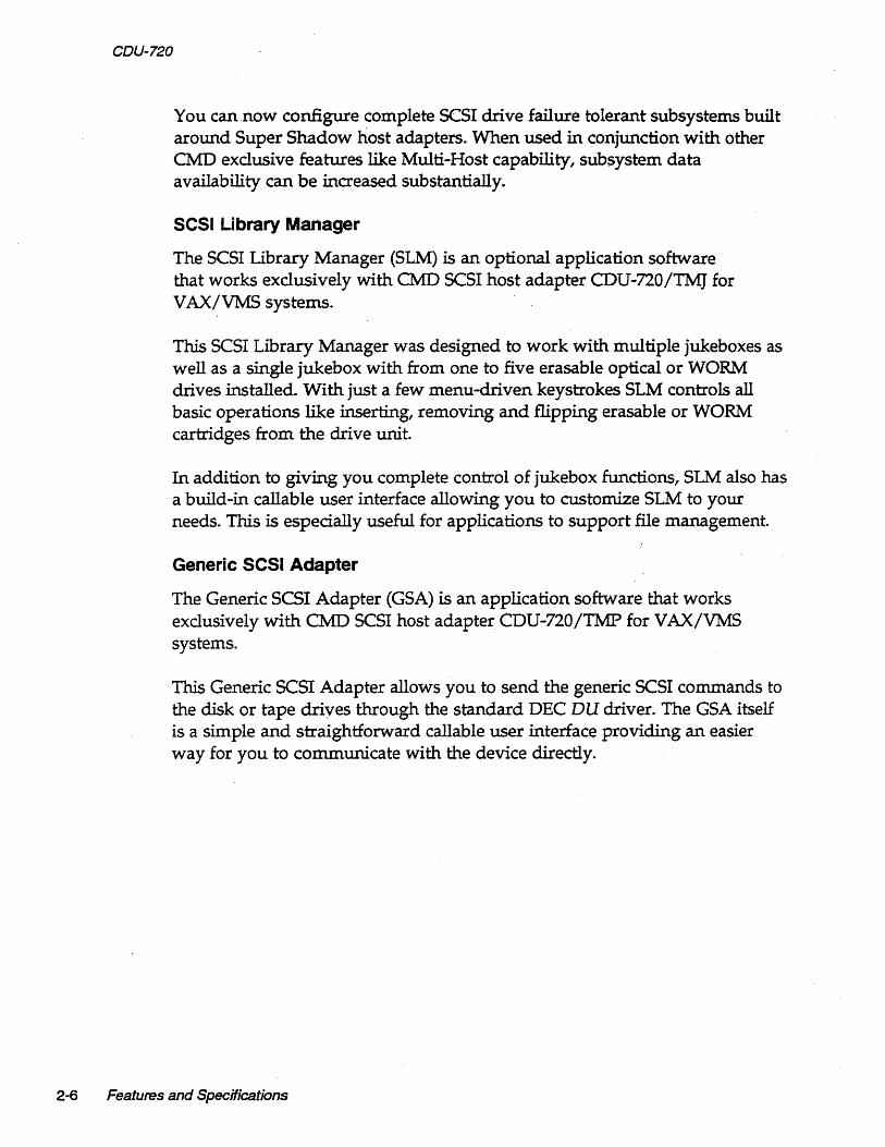
SCSI Bus Cabling
Single-ended-· The CDU-720 provides a 50-pin connector 01) to interface with external singel-ended SCSI devices.
• When the CDU-720 and the SCSI devices are installed in the same cabinet which meets EMI/RFI shielding requirements, a 2S-signal twisted-pair cable must be used for connecting the CDU-720 01) and the SCSI devices.
• When the CDU-720 and the SCSI devices are installed in separated cabinets, the shi~lded SCSI cable should be used to meet FCC requirements.
• A minimum conductor size of 2B-AWG must be used to minimize noise effects and ensure proper distribution of optional terminator power.
• The maximum cable length is 6.0-meters or 20-feet in single-ended channel.
Differential-The CDU-720 also provides a 50-pin connector 02) to interface with external differential SCSI devices.
• When the CDU-720 and the external SCSI devices are installed in the same cabinet which meets EMI/RFI shielding req~ements, a 2S-signal twisted-pair cable must be used for connecting the CDU-720 02) and the external SCSI devices. '
• When the CDU-720 and the external SCSI devices are installed in separated cabinets, the shielded SCSI cable should be used to meet FCC requirements. A 2S-signal twisted-pair cable must be used to eliminate the crosstalk between adjacent signals causing spurious pulses on differential signals which will occur even at slow data transfer rates and short cable distances. Each pair should be connected to the same signal, one wire to the positive and the other wire to the negative signal.
• Cables should conSist of conductors of 26-AWG or 2B-AWG. • The maximum cable length is 2S-meters or BO-feet in differential
channel.
Installation 3-13

CDU-720
SCSI Bus Termination
The CDU-720 can be installed in any position of the SCSI cable. If the CDU-720 is installed in either end of SCSI cable, on-board terminators should remain on board. If the CDU-720 is in the middle of the SCSI bus, on-board terminators should be removed.
Single-ended-The SCSI bus signals should be terminated with 220-ohms to +5-volts and 330-ohms to ground at each end of the cable. The CDU-720 provides on-board removable terminators (RN9, RNlO, and RN14), which are next to the SCSI connector Jl.
Differential-Every differential signal pair should be terminated with 330-ohms resistor between the negative signal and +5-volts, 330-ohms between the positive signal and ground, and l50-ohms between the positive and the negative signal at each end of the SCSI cable. Insert 330-ohm resistors at RNl, RN2, RN6 and RN7. Insert ISO-ohm resistors at RN3, RN4, RN5 and RN8. The resistor slots are located next to the connector J2.
SCSI Bus Terminator Power
Any SCSI terminator (on-drive or external) needs to be powered by at least one SCSI device, otherwise the SCSI signals will be pulled down. Typically an initiator (SCSI host adapter) provides the power to the on-board terminator, external SCSI terminator and on-drive terminator when the drive is powered off. Anytime an external SCSI terminator (instead of the on-drive SCSI terminator) is used, the SCSI terminator power option of the CDU-720 has to be enabled, i.e. install jumper shunt at WI or W3.
A minimum conductor size of 28-AWG shall be employed to minimize noise effects and ensure proper distribution of optional terminator power. The CDU-720 and CDU-722 supplies terminator power to the TERMPWR pin (Jl, pin 26; J2, pin 25 and 26), through a fuse, a diode and jumper block W2 for differential and W3 for single.-ended (see Table 3-14).
Table 3-14
W2
W2
W3
W3
Terminator Power Option
IN OUT IN
OUT
Differential SCSI terminator power enabled (F)
Differential SCSI terminator power disabled Single-ended SCSI tenninator power enabled (F)
Single-ended SCSI tenninator power disabled
Note that (F) means factory setting.
3-14 Installation

Installation Procedures
1 Determine the CSR address for the CDU-720 as explained in "Determining CSR Address."
WARNING Be sure to wear anti-static wrist straps or equivalent to protect the CDU-720 from electro-static damage.
2 Configure the hardware as explained in "Hardware Configuration."
3 Set the CDU-720 and Device SCSI !D's as explained in "SCSI Host Adapter ID Selection" and "SCSI Device ID Selection."
4 Choose a proper slot to place the CDU-720; and install it into that slot (see "CDU-720 Mounting Slot Selection").
5 Connect SCSI cable to J1 for single-ended or J2 for differential of the CDU-720 using cable specifications given in "SCSI Bus Cabling," see Figure 3-4.
WARNING In order to prevent accidental grounding or ~isconnection of terminator power, make sure that the pin 1 mark of SCSI cable matches with the pin 1 mark of SCSI device's connector before turning on the power.
Single-ended
CDU-720
Pin 1
Intemal Coble ----·o.::vt strtpe designates pin 1
Rgure 3-4: COlJ.720 cable connection
Installation 3-15

c.;UU-/~U
6 Continue SCSI cabling to connect up to seven SCSI devices to the CDU-720. See the example in Figure 3-5.
Host
J1 or J2 ID=7 T
SCSI device DUAO
SCSI device DUA1
SCSI Bus Cable
Figure 3-5: SCSI 10 and Cabling
T shows termination of SCSI bus
SCSI device DUA2
SCSI SCSI SCSI device device device DUA3 DUM DUAS
7 Terminate the SCSI bus at each physical end; see IIstSI Bus Termination."
If TERMPWR is needed for the bus, place jumper shunt on WI or W3 as explained in JlSCSI Bus Terminator Power" (see the example in Figure 3-5).
8 Power up the system and execute On-Board Utility to scan for the SCSI devices and assure that all devices are seen and functioning properly (see Chapter 4 for On-Board Utility).
9 Boot the system and test with the operating system.
3-16 Installation

4 Setup
This chapter will assist you in setting up the CDU-720 and your system for use.
On-Board Utility
The CDU-720 SCSI host adapter comes with a general purpose On-Board Utility for all systems. The On-Board Utility can test the sy?tem slot, SCSI cable, and SCSI devices connected to the CDU-720. Accessing the Utility can be done through PDP system or the RS-232 Port. Be sure to" complete utility functions, explained at the end of this chapter.
Accessing the Utility Through the PDP System
The On-Board Utility Program can be accessed by means of an ODT command for PDP systems. One example is shown with the SCSI host adapter set to the first disk CSR address.
NOTE Accessing the Utility from the PDP system insures that the host recognizes the CDU-710.
PDP-11124 Systems
Follow these instructions for using the Disk Utility with PDP-ll/24 Systems.
1 Halt the processor.
2 Hit the Boot Switch.
Setup 4-1

4-2 Setup
3 Enter CSR address plus 2 (in Octal), a slash, and 123456. See Table 4-1 for CSR Address Plus 2 configurations. Other CSR addresses can be found in Chapter 3 or Appendix C (see the example below).
Table 4-1 CSR Addresses Plus 2 Configurations
DISK: TAPE:
CSRAddress CSR Addr. Plus 2 CSRAddress CSR Addr. Plus 2
17772150 17772152 17774500 17774502 17760334 17760336 17760404 17760406 17760354 17760356 17760444 17760446 17760374 17760376 17760504 17760506 17760340 17760342 17760544 17760546 17760344 17760346 17760410 17760412 17760350 17760352 17760450 17760452 17760360 17760362 17760454 17760456
4 Enter CSR address plus 2 (in Octal), a slash, and 100 to load the utility to the system memory.
5 Enter 5000G.
EXAMPLE For steps 3 to 5 with CSR 17772150, enter the following:
7721521005400 123456 [ENTER]
7721521 100 [ENTER]
5000G . [ENTER]
The Utility program will begin executing as shown in Figure 4-1.
MAIN MENU
1 = BOOT DRIVE 2 = CONFIGURE LUN OFFSET 3 = FORMAT DRIVE 4 = QUALIFY DRIVE 5 = MANUAL REPLACE BAD SECTORS
CSR=n2150
6 = TEST DRIVE (READ, WRITE, AND VERIFY) 7 = ADDITIONAL SCSI COMMANDS
SELECT OPTION:
Rgure 4-1: PDP Main Menu

NOTE If the message appears "CONTROLLER NOT PRESENT," make sure CSR address is correct.
6 From the PDP Main Menu select option 1 or 7. 1 will boot the drive and 7 will bring you to the SCSI Host Adapter Utility.
PDP-11134 Systems
Follow these instructions for using the Disk Utility with PDP-11/34 Systems.
1 Enter ODT mode.
2 From the terminal, enter the following commands and press [ENTER]
after each command:
L YYYWY D 123456
L YYYWY DI00
Where yyyyyy = the last six digits of the CSR address plus 2 (see Table 4-1)
3 Enter the following commands and press [ENTER] after each command; the Utility program will the begin executing as shown in Figure 4-1:
L 5000 S
EXAMPLE For steps 2 and 3 with CSR address 17772150, enter:
L 772152 [ENTER]
D 123456 [ENTER]
L 772152 [ENTER]
D 100 [ENTER]
L 5000 S
Setup 4-3

COU-72U
4-4 Setup
Accessing the Utility Through the RS-232 Port
To access the utility from the RS-232 port, follow the instructions below.
1 Connect a terminal to the CDU-720's RS-232 port (10 pin connector). See Figure 4-2.
To Terminal
Figure 4-2: CDU-720 RS-232 Port
PIn 1
RS-232 Coble PIn 1
J2
2 Set the terminal baud rate to 9600 (8-bit data, I-stop bit, no parity) jump scroll.
3 Halt the system's CPU, reset the system, and hit carriage return on the terminal. The SCSI Host Adapter Utility will display as shown in Figure 4-3.
SCSI HOST ADAPTER UTILITY (REV. VYYXZZJ
x = UTILITY EXIT
[DISK] 1 = LOGICAL UNIT NUMBER OFFSET 2 = FORMAT DRIVE 3 = QUALIFY DRIVE 4 = MANUALLY REPLACE BAD BLOCKS 5 = ADDITIONAL UTILITIES
SELECT OPTION ?
Figure 4-3: SCSI Host Adapter Utility
[TAPE] 6 = LOGICAL UNIT NUMBER OFFSET 7 = ADDITIONAL UTILITIES

Once the SCSI Host Adapter Utility shows up, you can key in the number to select the desired option. Press [CTRL] + C at any time to return to the main menu.
4 Refer the next subsections for configurations. When completed, unplug the terminal, reset the system, and boot. DO NOT use the On-Board Utility while the system is running.
NOTE The following sections will illustrate the On-Board Utility from the RS-232 Port. There may be some variation in the Mairi Menu and the SCSI Host Adapter Utility Menu. If you are accessing from the Main Menu, simply chose the correct number for each option.
Changing LUN Offset
When a system has a HSC or in a VAX. cluster it will be necessary to change the LUN (Logical Unit Number) offset. Each MSCP drive requires a different Unit Number so that the unit numbers are not duplicated. If there are no other MSCP controllers in the system, the LUN offset can be 0.
If there exists another MSCP controller with four drives (0 to 3) in a VAX cluster configuration, then the L UN offset should be four or above. In the case that LUN offset is equal to 10, SCSI ID ° will be DUBIO and SCSI ID 1 will be DUBll. The drives will show up as such DUAO, DUAl, DUA2, DUA3, DUBIO, DUBll (see section, "SCSI ID for Target Drives" in Chapter 3 for explanation).
Follow these procedures to configure L UN offset.
1 Select option 1 from the SCSI Host Adapter Utility for disk drives; 6 for tape drives.
2 Enter the new value for LUN offset at the statement LUN OFFSET IS 0, ENTER NEW VALUE:
3 At the statement SAVE NEW VALUE (Y or N)? enter Y.
4 The monitor will display FORMAT CO:MPLETE when finished executing.
Setup 4-5

CUU-12U
4-6 Setup
Formatting the Drive
This section details formatting a drive. The COU-720 issues Format Unit Command to the selected SCSI disk drive and requests it to map out the defects on the Manufacture Defect List (MDL). Remember formatting a drive will rewrite all the sectors of that drive.
CMD recommends that you format all new drives. To format a drive, follow the steps below:
1 Select option 2 from the SCSI Host Adapter Utility.
2 Enter the device number from 0 to 6 in the statement DEVICE NUMBER?
<0 TO 6> DEV X.
3 Answer Y to the question FORMAT DRIVE X, ARE YOU SURE? if you want to continue.
4 At the statement WARNING DATA WILL BE DESTROYED, ARE YOU SURE?
enter Y if you want to continue.
5 The monitor displays WAIT while the drive is executing the format process.
6 The monitor will display COMPLETE when finished executing.
Qualifying the Drive
After formatting the device, CMD recommends you qualify devices by running this procedure at lease once without errors detected. The qualify program writes different patterns to the drive arid then verifies the data. If there are any bad sectors, the sectors will automatically be replaced and the statement XX XXXXXXXX BAD BLOCK REPLACED will appear. Follow the instructions below for qualifying a drive.
1 Select option 3 from the SCSI Host Adapter Utility.
2 Enter the device number at the statement DEVICE NUMBER? DEV <0 TO 6>
DEVX.
3 At the statement, READY TO TEST DEVICE X, ARE YOU SURE enter Y if you want to continue.

4 At the statement ...... WILL DESTROY DATA ON TIllS DEVICE, ARE YOU SURE?
enter Y if you want to continue.
5 The monitor will display QUALIFY STARTED <SEQUENTIAL WRITE & READ>!
<HIT <Break> TO ABORT>.
6 The monitor will display TESTING LOOP COUNT & BLOCK NUMBER:
7 Press [BREAK] to exit back to the SCSI Host Adapter Utility after you are sa tisfied with the qualifying process.
Manually Replacing Bad Sectors
This option allows you to replace bad sectors manually. The controller supports dynamic defect management which replaces defective sectors on-line so there is no need to manually replace bad sectors. However, if you wish to replace bad sectors manually follow these instructions; remember that any data in the sector will be lost:
1 Select option 4 from the SCSI Host Adapter Utility.
2 Enter the device number at the statement: DEVICE NUMBER ? DEV <0 TO 6>
DEVX:
3 Enter the logical block number in HEX at the statement
READY TO TEST DEVICE X,
ENTER THE BAD BLOCK NUMBER <:HEX> : xxxxx
4 The monitor will display -BAD BLOCK REPLACED- when finished executing.
Setup 4-7

lJLlV-It::U
4-8 Setup
Additional Utilities
To access additional utilities for disk drives, select option 5 from the main menu. To access additional utilities for tape drives, select option 7 from the main menu. The additional utilities menu will display as shown in Figure 4-4.
ADDITIONAL UTILlT1ES (REV. VYYXZZ) SN = 1278
D = DISPLAY SCSI DEVICE AND SET UP CONFIGURATION S = SEND SCSI COMMAND TO THE DEVICE T = TEST SCSI DEVICE R = FORMAT RCT BLOCK
SELECT OPTION ?
Figure 4-4: Utility Sub-menu
Displaying SCSI Device and Setting Up Configuration
Selection '0' can be used to change the controller default configurations such as those listed below:
• reset to default • number of disk and tape devices supported • SCSI reset enable/ disable • SCSI disconnect enable/ disable • sync/ async mode selection • tape buffer mode enable / disable • prevent medium removal enable/disable • disk write with verify enable/disable • remote density mode enable/ disable • default tape enable/disable • reconfigure device • autoboot start from floppy enable/ disable • write protect from controller jumper setting • truncate disk size for volume shadowing • eject removable disk cartridge after dismount
This utility can also scan/display the SCSI devices attached to the CDU-720 . . The CDU-720/TM will be shown as an example in the following display. To display SCSI devices and set up configuration follow the procedures below:

1 Select option D at the sub-menu (Figure 4-4), the following current configuration is displayed as shown in Figure 4-5.
NOTE
DEVO DUO, SCSI ID 0, LUN ° Disconnect ON, Sync Mode ON, Prevent Medium Removal ON, Write WNerify OFF
DEV1 DU1, SCSI ID 1, LUN 0 Disconnect ON, Sync Mode ON, Prevent Medium Removal ON, Write WNerify OFF
DEV2 DU2, SCSI ID 2, LUN 0 Disconnect ON, Sync Mode ON, Prevent Medium Removal ON, Write WNerify OFF
DEV3 DU3, SCSI ID 3, LUN 0 Disconnect ON, Sync Mode ON, Prevent Medium Removal ON, Write WNerify OFF
DEV4 MUO, SCSI ID 4, LUN 0 Disconnect ON, Sync Mode ON, Buffer Mode ON
DEV5 MU1, SCSIID 5, LUN 0 Disconnect ON, Sync Mode ON, Buffer Mode ON
DEV6 MU2, SCSI ID 6, LUN 0 Disconnect ON, Sync Mode ON, Buffer Mode ON
DEV7 SCSIID 7, HOST ADAPTER SCSI Reset ON, Density Mode ON, Default Tape OFF Boot Floppy OFF, Jumper Write Protect OFF, Eject Disk O~, Truncate Size OFF
Figure 4-5: Current configuration, default
If Truncate Size is toggled, JJTruncate Mode ON" will display under each disk device options and at the bottom when configuration is displayed.
Setup 4-9

VI.JV-,.r..v
4-10 Setup
2 To change the configuration, enter Yat the statement CHANGE
CONFIGURATION? rt IN) The menu shown in Figure 4-6 will display.
NOTE See subsection, "Unit Numbering" before trying to reconfigure devices.
R = Toggle SCSI Reset D = Toggle Disconnect S = Toggle Sync/ Async C = Reconfigure Device U = Toggle Default Tape (Tape Only) A = Autoboot Start From Floppy Drive
M = Toggle Density Mode B = Toggle Bufferrrruncate Mode (TapeJDisk) W = Toggle Write WNerify (Disk only) P = Toggle Prevent Medium Removal (Disk only)
N = Write Protect from Controller Jumper Setting V = Truncate Disk Size for Volume Shadowing E = Eject Disk after Dismount L = ReservelRelease Disk Option T = Reset All Device Modes to Default Z = Reset Controller to Default Configurtation
Figure 4-6: Configuration change
The following list is an explanation of the selections in Figure 4-6.
R = Toggle SCSI reset-Choosing this option will toggle the controller's ability to issue SCSI resets. This should be turned off when multi-hosting is desired.
D = Toggle Disconnect-This option allows you to enable or disable disconnect for each device. If enabled the controller will indicate its ability to disc<;>nnect during the SCSI identify message.
S = Toggle SyndAsync-This option allows you to configure each device for synchronous or asynchronous operations. If synchronous is selected, the controller will attempt a synchronous message exchange with the device. If the device accepts the message ~x~ge, they will transfer data synchronously, otherwise they will transfer asynchronously.
C = Reconfigure Device--This option allows you to reconfigure the device at any time.
M = Toggle Density Mode-This option allows you to configure the controller for remote density selection. If enabled, remote density selection may take place. If enabled, the controller reports itself as a 'TUBI.' If disabled, it reports itself as a 'TKSO.'

B = Toggle Bufferfrruncate Mode (Tape!Disk)-For tape devices, this option allows the controller to configure each individual tape device for write caching. If enabled, the tape device will send command complete message and good status to the controller once the data as been transferred to the tape device's internal buffers. If disabled, such message and status will be sent when the data is actually written to the tape. For disk devices, you may toggle truncate disk size, see "V = Truncate Disk Size for Volume Shadowing" for explanation.
W = Toggle Write WNerify-This option will allow the SCSI command Write with Verify to be issued for MSCP write with verify modifier. When set to OFF (which is the default), the normal write command will be issued.
P = Prevent Medium Removal-This option is for removable disk drives only. When set to ON, a "Prevent Medium Removal" will be issued to a drive when it is mounted by VMS. This will disable the eject media push-button in front of the drive. An "Allow Medium Removal" will be issued when the drive is dismounted by VMS and the pushbutton will be enabled. This features can be disabled and the media can be ejected at anytime.
U = Toggle Default Tape-This option allows you ,to force the presence of a tape unit to the operating system even if one does not exist. This is needed for some operating systems when the controller is connected to devices with a long self test procedure after power-up. If it is disabled, only units connected to the controller are seen by the operating system.
A = Autoboot" Start From Floppy Drive-This option allows you to set the system to boot directly from the first floppy drive; if no floppy drive is present, the system will begin to boot from the first device.
N = Write Protect from Controller Jumper Setting-This option is not available at the present time. Default is OFF.
v = Truncate Disk Size for Volume Shadowing-This option allows the size of the disk to be truncated to multiples of 126 blocks to allow VMS volume shadowing copy process to reach higher performance. The message "** WARNING ** Truncate Size ON/OFF will be toggled, Are you sure?" will display before truncate switch can be toggled. If this feature is used on a disk that contains valid data, the data must be removed and later restored after turning this feature ON.
Setup 4-11

4-12 Setup
E = Eject Disk after Dismount-This option allows you to specify whether the removable disk cartridges will eject from the drive after dismount.
L = ReservelRelease Disk Option-This option is to let the MSCP ON-LINE exclusive use modifier to be operable.
T = Reset all Device Modes to Default-These modes are---disconnect, synchronous, Prevent Medium Removal, Write with Verify, and Buffer modes, etc.
Z = Reset Controller to Default Configuration-This option allows the you to set the controller to its factory default configuration. This will set the CDU-720/TM to support four disk drives, three tape drives; the CDU-720/M to support seven disk drives; CDU-720/T to support seven tape drives; disconnect, SCSI reset, synchronous communication, buffer mode, prevent medium removal and density selection enabled; write with verify, write protect disabled, reserve/release disk disabled, and default tape disabled. Use this feature ALWAYS before you reconfigure the board.
3 To reconfigure the device select option C and the screen will prompt you to answer the next series of questions as shown in F:igure 4-7.
4 Enter the number of disk and/or tapes. Default configuration is four disks, and three tapes; it is not necessary to configure if running less
Number of Disks? (0-7) 4 DUO to be Reconfigured ? (YIN) N DU1 to be Reconfigured? (YIN) N DU2 to be Reconfigured ? (YIN) N DU3 to be Reconfigured? (YIN) N
Number of Tapes? (0-3) 3 MUO to be Reconfigured ? (YIN) N MU1 to be Reconfigured? (YIN) N MU2 to be Reconfigured ? (YIN) N
Rgure 4-7: SCSI ha.t adapter 10 change
than four disks and three tapes.

NOTE If zero is selected for the number of disks or tapes disable the corresponding CSR address as shown in Tables 3-1 to 3-4 (Chapter 3). Do not use 0 disk and/or 0 tape configuration in the above setup.
Answer Y or N to reconfigure each of the disks or tapes. If you answer Y, the screen will prompt you with these questions:
(DUX SCSI ID? <0-7> J l_D_U_X_L_U_N_?_<_O-_3_> ___ -__________________________________ _
Rgure 4-8: Disk and Tape Configuration Change
NOTE This LUN is SCSI LUN; it is normally O. This is used only for devices that support multiple LUNs.
5 When you have completed these instructions the display will show your current configuration and prompt you again with the question CHANGE
CONFIGURATION? ('fIN). Enter N; this will cause the CDU-720 to scan the SCSI bus.
The utility will display your current configuration with manufacturer's name, model number, and firmware revisions for each device. Record this information for future use.
Sending SCSI Commands To The Device
Selection '5' can be used to send SCSI commands to the selected disk/tape drives directly.
This option is used to send a 6-, 10-, or 12-byte command to a SCSI device. Follow these procedures to send SCSI commands to the device:
1 Enter S from the /I Additional Utilities" Menu. (Be sure you have correctly selected either 5 from the SCSI Host Adapter Utility for disk drives, or 7 for tape drives.)
2 At the question DEVICE NUMBER? DEV <0-6> DEV enter the device number.
Setup 4-13

4-14 Setup
3 Enter the command sequence at the statement
READY TO TEST DEVICE X EDIT CDB <HEX> ........ <E.5C> TO TERMINATE EDITING .........
BYTE 0000= 00
If a 6- or 10-byte command is used, press [ESC] to terminate command editing. If a 12-byte command is used, command editing is terminated automatically.
4 At the statement WRITE DATA TO THE DEVICE? <Y OR N> enter N to immediately send the command if SCSI command does not require a data out phase.
Or enter Y to send data to the device after the command phase if SCSI command requires a data out phase. Enter the data and enter [ESC] to terminate editing. The statement SAVE EDITED DATA IN BUFFER ?
<Y OR N> will appear. Enter Y to save data in the buffer; or enter N to erase edited data after the command is sent.
Testing SCSI Device
Selection 'T' can be used to read only, write and read selected disk drive, and/ or write and read selected tape drive continuously. This is a diagnostic tool to help with installation and testing. Follow the procedures below to test the SCSI device.
1 Enter T from the /I Additional Utilities" menu. (Be sure you have correctly selected either 5 from the SCSI Host Adapter Utility for disk drives, or 7 for tape drives.)
2 At the question DEVICE NUMBER ? DEV <0-6> DEV enter the device number.
3 When testing for disk devices, at the statement READY TO TEST DEVICE X,
00 YOU WANT TO READ ONLY? <Y OR N> enter Y to read only.
Enter Nto write and read. The question ARE YOU SURE? will display. Enter Y to write and read to the device.
WARNING Nwill destroy all data on the device.
When testing for tape devices, the statement ARE YOU SURE? will display. Enter Y to test the device.

4 At the statement, IS THIS FOR DUAL HOSTS QUALIFICATION TE5TI <Y IN>, enter Y. Enter N for single host qualification.
The test will continue until you abort. Allow the test to continue for a few minutes for new devices and ten minutes for suspected bad devices. Press [BREAK] or [CTAl] + C to abort and exit back to the SCSI Host Adapter Utility.
Formatting ReT Block
Selection 'R' can be used to format the RCT blocks of the disk drive selected. This command writes zeros in the last logical block of the device. If you try to skip the formatting process and directly use the drive, you must use this option to eliminate "unrecoverable bad RCT block." However, CMD recommends you format the drive. To format the RCT block follow these instructions:
1 Select R from the /I Additional Utilities." (Be sure you have previously selected 5 from the SCSI Host Adapter Utility for disk drives.)
2 Enter device number at the statement: DEVICE NUMBER? DEV <0-6> DEV.
If device is off-line the following statement will appear, DEVICE OFFLINE,
RESELECT OR PROCEED? (RIP). Enter R to reselect or P to proceed.
3 FORMAT COMPLETE will display when RCT block has been formatted.
Completing Utility Functions
The following procedures should be completed when you have accessed the On-Board Utility through the RS-232 port. .
1 Use the On-Board Utility to verify SCSI cable and SCSI devices connected to the CDU-720 after installing the CDU-720 in the Unibus slot.
2 After verifying the SCSI connections, disconnect RS-232 cable from the back panel, and reset the system.
NOTE If the terminal is connected, this may cause the OnBoard Utility to be invoked during system operation and will take control of the Host Adapter from VMS.
Setup 4-15

vLlU-/~U
4-16 Setup
The following procedures should be completed when you have accessed the On-Board Utility through the Virtual Console of the LSI or VAX systems.
1 Use the On-Board Utility to verify the Unibus slot seating, SCSI cable, and SCSI devices connected to the CDU-720 after installing the CDU-720 in the Unibus slot.
2 After verifying the SCSI connections, reset the system.
Unit Numbering For Devices
This section explains configuring unit numbers. Unit numbers may be changed by using the "Configure LUN Offset" from the main menu. If you used the 'D' option from the II Additional Utilities" menu, the terminal will display the MU and/or DU numbers as shown in Table 4-2, factory default settings for unit numbers.

Table 4-2 Default for Unit Numbers
CDU-720rr SCSIID On-Board Utility Operating System Unit No.
0 MUD 0
1 MUI 1
2 MU2 2
3 MU3 3
4 MU4 4
S MUS S
6 MU6 6
CDU-7201M SCSIID On-Board Utility Operating System Unit No.
0 DUO 0
1 DUI 1
2 DU2 2
3 DU3 3
4 DU4 4
S DUS S
6 DU6 6
CDU-720trM SCSIID On-Board Utility Operat;ing System Unit No.
0 DUO 0
1 DUI 1
2 DU2 2
3 DU3 3
4 MUD 0
5 MUI 1
6 MU2 2
An example on the next page is given for each type of controller to show how the unit numbers can be determined. Refer to Figure 4-5 if necessary.
COU-7201T-Tape drives must be configured starting from SCSI ID 0 to properly use the information from Table 4-2. MUO will be unit number 0; this is with LUN offset set to O. Setting the LUN offset to 10 will change the MU number to 10 (ie., MU10), making the unit number 10.
COU-720/M-Disk drives must be configured starting from SCSI ID 0 to properly use the information from Table 4-2. DUO will be unit number o. This is with LUN offset set to O. Setting the LUN offset to 10 will change the DU number to 10 (ie., DU10), making the unit number 10.
Setup 4-17

4-18 Setup
CDU-7201TM-Default is four disk drives and three tape as shown in Table 4-2. If you have more than four disk drives or three tape drives, follow these guidelines-disk drives must start at SCSI ID 0 and tape drives must start after the last disk drive's SCSI ID number and reconfigure the CDU-720/TM (see subsection, "Displaying SCSI Devices and Setting Up Configuration"). Note the example below: .
SCSI ID 0 disk SCSI ID 1 disk SCSI ID 2 disk SCSI ID 3 disk SCSI ID 4 disk
SCSI ID 5 tape SCSI ID 6 tape
SCSI ID 7 is initiator (CDU-720 /TM)
The MU and DU numbers are the unit numbers mapped back to the operating system. If the CDU-720 /TM is configured following these guidelines, you can apply this formula to determine the unit number mapped back to the operating system:
SCSI ID of the disk drive + the LUN offset for disk = unit number for disk
SCSI ID of tape drive number of disk drives
+ LUN offset for tapes = unit number for tape

Multi-Hosting Configuration
The following is a list of software requirements for multi-hosting; refer to Appendix A for supported multi-hosting devices:
• VMS version 5.3 or above • VAX cluster software must be running on both systems with at least
one of the DEC's interconnects operational • Tape drives can only be mounted to one system at a time • Allocation classes must be the same for all systems when installing
disk drives (value must not equal 0).
Using VMS and the CDU-720/M or CDU-720/TM, you can multi-host by following the instructions below:
1 Configure the CDU-720 to SCSI ID 7 for the first computer; configure the CDU-720 to SCSI ID 6 for the second computer. If you need to alter the Host Adapter SCSI ID change the jumper settings as shown in Table 4-3.
Table 4-3 Host Adapter 10 Selection
W6-1 W6-2 W6-3 Initiator ID
IN IN IN Host adapter ID ::; 7 highest priority (F)
IN IN OUT Host adapter ID = 6
IN OUT IN Host adapter ID = 5
IN OUT OUT Host adapter ID = 4
OUT IN IN Host adapter ID = 3
OUT IN OUT Host adapter ID = 2
OUT OUT IN Host adapter ID = 1
OUT OUT OUT Host adapter ID = 0, lowest priority
Note that (F) means factory setting.
Setup 4-19

4-20 Setup
2 From the Additional Utilities Menu in the On-Board Utility, follow these instructions:
a Select option D to display current configuration. b Answer Y to the statement CHANGE CONFIGURATION? rt IN) The
menu shown in Figure 4-5 will display. c Select Z to reset configuration back to default. d Answer Y to reconfigure the adapter.
NOTE If you ever reconfigure the board, you must reset the configuration to default using selection Z.
e Select R to toggle SCSI reset. Then set the SCSI reset to OFF. Do this for all SCSI host adapters to be multi-hosted.
f Answer Yto reconfigure the adapter. 9 Select C to reconfigure the device. Then configure the CDU-720 for
exact number of disks and tapes. This will inhibit scanning of other host adapters (see Figure 4-S).
h If other MSCP disks are in the cluster, follow the rules in the subsection "Changing LUN Offset" in liOn-Board Utility" so that each device has a unique unit number. Exit out of the On-Board Utility.
NOTE In a multi-hosting system the physical disk device name must be identical on both systems.
3 Terminate both physical ends of the SCSI bus.
Single-ended-If the CDU-720 is at either end of the SCSI bus, remove on-board terminators, RN9, RNIO, RN14, and use a pass-through terminator as close to the board as possible. If the CDU-720 is in the middle of the SCSI bus, RN9, RNIO and RN14 terminators must be removed, do not use pass through terminators.
Differential-If the CDU-720 is at either end of the SCSI bus, remove on-board terminators, RNl, RN2, RN3, RN4, RNS, RN6, RN7, RN8 and use a pass-through terminator as close to the board as possible. If the CDU-720 is in the middle of the SCSI bus, RNl, RN2, RN3, RN4, RNS, RN6, RN7, and RN8 terminators must be removed, do not use pass through terminators.

In the event that one system becomes inoperable with only two nodes in the VAX cluster, a quorum disk must be used to count as a vote; this keeps the other system running. Refer to VMS V AXcluster manual order number AA-LA27 A-TE to set up a quorum disk and a VAX cluster.
NOTE When running cluster _config.com on a system with only Ethernet as a computer interconnect, answer Yes for the question, JlWILL THIS BE A SA1ELLITE NODE?"
Partitioning Configuration
You may partition a device into two or four sections under VMS or ill TRIX using the CDU-720/M or CDU-720/TM. To partition a device, follow the instructions below.
1 Configure the SCSI devices as explained in the section JlDisplaying SCSI Device and Setting Up Configuration."
2 Select D from JI Additional Utilities." The current configuration will display all physical devices as shown in the example in Figure 4-9:
DEVO DUO, SCSI ID 0, LUN 0 Disconnect ON, Sync Mode ON, Prevent Medium Removal ON, Write WNerify OFF
DEV1 DU1, SCSI ID 1, LUN 0 Disconnect ON, Sync Mode ON, Prevent Medium Removal ON, Write WNerify OFF
DEV2 DU2, SCSIID 2, LUN 0 Disconnect ON, Sync Mode ON, Prevent Medium Removal ON, Write WNerify OFF
DEV3 DU3, SCSIID 3, LUN 0 Disconnect ON, Sync Mode ON, Prevent Medium Removal ON, Write WNerify OFF
DEV4 MUO, SCSIID 4, LUN 0 Disconnect ON, Sync Mode ON, Buffer Mode ON
DEV5 MU1, SCSIID 5, LUN 0 Disconnect ON, Sync Mode ON, Buffer Mode ON
DEV6 MU2, SCSI ID 6, LUN 0 Disconnect ON, Sync Mode ON, Buffer Mode ON
DEV7 SCSI ID 7, HOST ADAPTER SCSI Reset ON, Density Mode ON, Default Tape OFF Boot Floppy OFF, Jumper Write Protect OFF, Eject Disk ON, Truncate Size OFF
Rgure 4-9: Current configuration
Setup 4-21

c.;uu-/;.c.u
4-22 Setup
3 Answer Y to the question that appears on the screen: CHANGE
CONFIGURATION \f /N)? Figure 4-10 will display:
R = Toggle SCSI Reset D = Toggle Disconnect S = Toggle Sync/ Async C = Reconfigure Device U = Toggle Default Tape (Tape Only) A = Autoboot Start From Floppy Drive
M = Toggle Density Mode B = Toggle BufferlTruncate Mode (TapelDisk) W = Toggle Write WNerify (Disk only) P = Toggle Prevent Medium Removal (Disk only)
N = Write Protect from Controller Jumper Setting V = Truncate Disk Size Jor Volume Shadowing E = Eject Disk after Dismount T = Reset All Device Modes to Default Z = Reset Controller to Default Configurtation
Figure 4-10: Configuration change
4 Select Z to reset configuration back to default. Answer Y to reconfigure the adapter. This step is IMPERATIVE!
NOTE If you ever reconfigure the board, you must reset the configuration to default using selection Z.
5 Select Option C. Answer Y to the devices to be partitioned as shown in the example in Figure 4-11:
Number of Disks? (0-7) 4 [total number of logical disks} DUO to be Reconfigured? (YIN) Y DUO SCSI ID? (0-7) 0 DUO LUN ? (0-3) 0 Number of Partitions ? (NONE, 2,4) 2 [N is the default] DU2 to be Reconfigured ? (YIN) Y DU2 SCSI ID ? (0-7) 1 DU2 LUN ? (0-3) 1 Number of Partitions ? (NONE, 2, 4) 2 [N is the default1-
Number of Tapes? (0-3) 3 MUO to be Reconfigured? (YIN) N MU1 to be Reconfigured? (YIN) N MU2 to be Reconfigured? (YIN) N
Figure 4-11: Partitioning example

CDU-720
After you have completed configuration, the system will display device configuration as shown in the example in Figure 4-12:
DEVO DUO, SCSIID 0, LUN 0 MICROP 1598-15MD1063303S1125 Disconnect ON, Sync Mode ON, Prevent Medium Removal ON, Write WNerify OFF
DEV1 DU1, SCSI ID 0, LUN 0 MICROP 1598-15MD1063303S1125 Disconnect ON, Sync Mode ON, Prevent Medium Removal ON, Write WNerify OFF
DEV2 DU2, SCSI ID 1. LUN 0 MICROP 1588-15MB10368101C09 Disconnect ON, Sync Mode ON, Prevent Medium Removal ON, Write WNerify OFF
DEV3 DU3, SCSI ID 1, LUN 0 MICROP 1588-15MB10368101C09 Disconnect ON, Sync Mode ON, Prevent Medium Removal ON, Write WNerify OFF
DEV4 MUO, SCSI 10 4, LUN 0 Disconnect ON, Sync Mode ON, Buffer Mode ON
DEV5 MU1, SCSI 10 5, LUN 0 Disconnect ON, Sync Mode ON, Buffer Mode ON
DEV6 MU2, SCSI 10 6, LUN 0 Disconnect ON, Sync Mode ON, Buffer Mode ON
DEV7 SCSI ID 7, HOST ADAPTER SCSI Reset ON, Density Mode ON, Default Tape OFF Boot Floppy OFF, Jumper Write Protect OFF, Eject Disk,ON, Truncate Size OFF
Figure 4-12: Current configuration
6 Format ReT block for each partition of each device. See "Formatting ReT Block" in "Additional Utilities."
7 Exit out of the On-Board Utility.
NOTE The system considers each partition as a device even though the location (LUN) is the same.
SetuD 4-23

CDU-720
Hardware Shadowing Configuration
A.-~A. Setuo
This section explains how to configure the CDU-720/TMS and SCSI drives into shadow sets. A maximum of three shadow sets can be formed with each controller. For the purpose of this explanation, four disk drives will be divided into two shadow sets with three remaining tape drives as shown below:
DUO = SCSI ID 0 DSO = SCSI ID 1 DUI = SCSI ID 2 DSI = SCSI ID 3 MUO = SCSI ID 4 MUI = SCSI ID 5 MU2 = SCSI ID 6
Primary Shadow drive of DUO Primary Shadow drive of DUI
Configuration Instructions
Follow the instructions below for configuring shadow sets.
1 Select 5 from the SCSI Host Adapter Utility.
2 Select D from the /I Additional Utilities" to display cUrrent configuration.
3 Answer Y to the question: CHANGE CONFIGURATION? \i IN). The menu shown in Figure 4-5 will display.
4 Select Z to reset configuration back to default. Answer Y to reconfigure the adapter. This step is IMPERATIVE!
NOTE If you ever reconfigure the board, you must reset the configuration to default using selection Z and then reconfigure.

5 Select C to reconfigure the device; see Figure 4-13 for instructions.
Number of Disks (including shadow units)? (0 - 7) 4 Number of Shadow sets? (0 - 2) 2
DUO to be Reconfigured? (YIN) Y DUO SCSI ID ? (0 - 7) 0 DUO LUN ? (0 - 3) 0
Shadow units exist? (YIN) Y OSO SCSI 10 ? (0 - 7) 1 DSO LUN ? (0-3) 0 DU 1 to be Reconfigured ? (YIN) Y OU1 SCSI ID ? (0 - 7) 2 DU1 LUN ? (0 - 3) 0
Shadow units exist? (YIN) Y DS1 SCSI 10 ? (0 - 7) 3 DS1 LUN ? (0-3) 0
Number of Tapes? (0-3) 3 MUO to be Reconfigured? (YIN) Y MUO SCSI ID ? (0 - 7) 4 MUO LUN ? (0 - 3) 0 MU1 to be Reconfigured? (YIN) Y MU 1 SCS I I D ? (0 - 7) 5 MU1 LUN ? (0 - 3) 0 MU2 to be Reconfigured? (YIN) Y MU2 SCSI ID ? (0 - 7) 6 MU2 LUN ? (0 - 3) 0
Figure 4-13: Hardware Shadowing example
CDU-720
Setup 4-25

CDU-720
4-26 SetuD
6 After you have completed configuration, the system will display device configuration as shown in the example in Figure 4-14:
DEVO DUO, SCSI ID a, LUN a Disconnect ON, Sync Mode ON, Prevent Medium Removal ON, Write WNerify OFF
DEV1 DU1, SCSI ID 2, LUN a Disconnect ON, Sync Mode ON, Prevent Medium Removal ON, Write WNerify OFF
DEV2 DSO, SCSI ID 1, LUN a Disconnect ON: Sync Mode ON, Prevent Medium Removal ON, Write WNerify OFF
DEV3 DS1, SCSI ID 3, LUN a Disconnect ON, Sync Mode ON, Prevent Medium Removal ON, Write WNerify OFF
DEV4 MUD, SCSI ID 4, LUN a Disconnect ON, Sync Mode ON, Buffer Mode ON
DEV5 MU1, SCSIID 5, LUN a Disconnect ON, Sync Mode ON, Buffer Mode ON
DEV6 MU2, SCSI ID 6, LUN 0 Disconnect ON, Sync Mode ON, Buffer Mode ON
DEV7 SCSI ID 7, HOST ADAPTER SCSI Reset ON, Density Mode ON, Default Tape OFF Boot Floppy OFF, Jumper Write Protect OFF, Eject Disk ON, Truncate Size OFF
Figure 4-14: Current configuration
7 Then answer N to the question: CHANGE CONFIGURATION? (YIN) and exit out of the On-Board Utility.
Detecting Shadowing Errors Using VMS
The following instructions will help you detect shadowing errors and shadowing drive failure.
1 At the system prompt, enter show dev duo
2 Check the error count for shadowed disk drives.
3 If errors are detected, follow the instructions given in Appendix C, "Troubleshooting," to view IIController Dependent Information."

CDU-720
Look for information describing which drive has failed such as given below:
/ID x/ /LUNx/ /PORx/
Where: x is the variable used to represent the ID, LUN, and Port of the failed disk drive.
4 Back up the remaining good shadow set member.
5 Shut down the system.
6 Replace the drive.
7 Enter the On-Board Utility and follow these instructions: a Select option D. The current configuration will display. b Answer Y to the question: 00 YOU WANT TO CLEAR SHADOW FAILED
STATUS? <YIN> c Answer N to the question: CHANGE CONFIGURA!ION <YIN>
d Exit On-Board Utility.
8 Boot the system.
9 Initialize the specified shadow set in VMS.
10 Restore the backup copy to the specified shadow set.
11 Put the specified drives back on-line by mounting them to VMS.
VMS Configuration
If you followed procedures in "Determining CSR Address" in Chapter 3, VMS software will automatically configure new devices added. NO other configuration is required. If VMS does not, run Auto Configure as shown in AppendixD.
Setup 4-27

CDU-720
UL TRIX Configuration
4-28 Setup
VAX and DEC systems uSing ULTRIX software must be manually configured to access the CDU-720 boards.
First, examine current configuration file to determine which controllers and devices are already connected to the system. Then refer to the respective sections for configuration procedures for the CDU-720/T, COU-720/M, CDU-720/TM.
CDU-720rr
Edit the configuration file by performing the following instructions for the COU-720fT. Note, the CDU-720/T must be configured with a higher klesiu number, higher uq number, and higher tms number than any other kIesiu controller in the configuration file.
1 Make sure the following two lines are in the configuration file:
adapter uba& at nexus?
Where ? = the system will fill in this variable (simply enter'this ? ). & = the node ID of the Unibus adapter.
2 Connect the controller to the node on the Unibus by entering the following line:
controller klesiu1} at uba&
Where 1} = the variable number that represents the COU-720/T. & = same number used in step 1.
3 Tell ULTRIX what the name of the controller will be:
controller uq# at kIesiu1} csr XXXXXXXX vector uqintr
Where 1} = the same number used in step 2. # = the variable used to represent the controller. XXXXXXXX = CSR address.

CDU-720
4 Name the tape drives and list drive unit by entering the following line:
tape tmsO at uq# drivea tape tmsl at uq# drive~
Where # = the same number used to represent the controller in step 3. a = the MU number in the On-Board Utility displays this configuration. ~ = the MU number in the On-Board Utility displays this configuration different than a.
CDU-7201M
Edit the configuration file by performing the following instructions for the CDU-720/M. Note the CDU-720/M must be installed with a higher node ID number, higher klesib number, higher ra number, and higher uq number than any other kdb and klesib controller in the configuration file.
1 Make sure the following two lines are in the configuration file:
adapter uba& at nexus?
Where ? = the system will fill in this variable (simply enter this ?). & = the node ID of the Unibus adapter.
2 Connect the controller Unibus by entering the following line:
controller udat} at uba&
Where t} = the variable number that represents the CDU-720/M. & = the same number used in step 1.
3 Tell ULTRIX what the name of the controller will be:
controller uq# at uda1} CST XXXXXXXX vector uqintr
Where # = the variable used to represent the controller. t} = the variable used in Step 2. XXXXXXXX = CSR address.
Setup 4-29

CDU-720
4-30 Setup
4 Name the tape drives and list drive unit by entering the following line:
disk raO at uq# drivea. disk ral at uq# drive~
Where # = the same number used to represent the controller in step 3. a. = the DU number in the On-Board Utility displays this configuration. ~ = the DU number in the On-Board Utility displays this configuration different than a..
CDU-7201TM
Edit the configuration file by performing the following instructions for the CDU-720/TM. Note the CDU-720/TM must be configured with a higher klesiu number, higher uq number, and higher tms numbers than any other klesiu controller; and a higher uda number, higher uq number, and higher ra number than any other uba controller in the configuration file.
1 Make sure the following two lines are in the configur~tion file:
adapter uba& at nexus?
Where ? = the system will fill in this variable (simply enter this? ). & = the node ID of the Unibus adapter.
2 Connect the controller the Unibus by entering the following line:
contro ller klesiuf> at uba& controller uda# at uba&
Where t} = the variable number that represents the CDU-720/TM. & = the same number used in step 1.

CDU-720
3 Tell UL TRIX what the name of the controller for the different functions will be:
controller uqV' at klesiui} CST XXXXXXXX vector uqintr controller uql1 at udal CST XXXXXXXX vector uqintr
Where V' = variable used to represent the controller . .6. = variable used to represent the controller (unique fromV' above). i} = the same number used in step 3 representing the controller. # = the same number used in step 3 representing the controller. XXXXXXXX = CSR address.
4 Name the tape drives and list drive unit by entering the following line:
tape tmsO at uq V' drivea. tape tmsl at uqV' drivef3 disk raO at uq.6. drivea. disk ral at uql1 drive~
Where V' = the same number used to represent the controll~r in step 4 . .6. = variable used to represent the controller (unique from V' above). a. = the MU number in the On-Board Utility displays this configuration. ~ = the DU number in the On-Board Utility displays this configuration.,
Setup 4-31

CDU-720
4-32 Setup

5 SCSI Basics
This chapt~.r consists of a SCSI glo~sary, SCSI commands ~ed by the CDU-720 for MSCP and TMSCP emulation, SCSI status codes, SCSI messages, SCSI single-ended and differential signals.
SCSI Glossary
The following is a glossary of frequently used SCSI terms. ;
Connect-The function that occurs when an initiator selects a target to start an operation.
Disconnect-The function that occurs when a target release control of the SCSI bus, allowing it to go to the BUS FREE phase.
Initiator-A SCSI device (usually a host system) that requests an operation to be performed by another SCSI device.
LUN-Logic Unit Number.
Peripheral device-A peripheral that can be attached to a SCSI device (e.g., magnetic disk, magnetic tape, or optical disk).
Reconnect -The function that occurs when a target selects an initiator to continue an operation after a disconnect.
SCSI address--The octal representation of the unique address (0-7) assigned to an SCSI device. This address would normally be assigned and set in the SCSI device during system installation.
SCSI Basics 5-1

CDU-720
SCSI ID-The bit-significant representation of the SCSI address referring to one of the signal lines DB (7-0).
SCSI device-A host computer adapter or a peripheral controller or an intelligent peripheral that can be attached to the SCSI bus.
Target-A SCSI device that performs an operation requested by an initiator.
SCSI Commands
SCSI commands used by the CDU-720/TM for MSCP emulation "are listed in Table 5-1.
Table 5-1
Code
OOh
01h
03h
04h
07h
OBh
OAh
OBh 12h 1Sh
16h 17h
1Ah
1Bh 1Eh
25h
2Bh
2Ah
2Bh 3Eh
3Fh
SCSI Commands (MSCP)
Command Name
Test Unit Ready
Rezero Unit
Request Sense
Format Unit (1)
Reassign Block
Read
Write
Seek
Inquiry
Mode Select
Reserve Unit
Release Unit
Mode Sense
Start/Stop Unit
" Prevent/Allow Medium Removal
Read Capacity
Extended Read
Extended Write
Extended Seek
Read Long (2) Write Long(2)
(1 )The Format Unit command is used by the On-Board Utility only.
(2)These commands are used if the drives support them.
5-2 SCSI Basics

CDU-720
SCSI commands used by the CDU-720/TM for TMSCP emulation are listed in Table 5-2.
Table 5-2
Code
OOh 01h
03h
08h
OAh
IOh
Ilh
12h ISh
16h
17h I9h
IAh
IBh
IEh
SCSI Status
SCSI Commands (TMSCP)
Command Name
Test Unit Ready
Rewind
Request Sense
Read
Write
Write Filemarks
Space
Inquiry
Mode Select
Reserve Unit
Release Unit
Erase
Mode Sense
Load/Unload
Prevent/ Allow M~dium Removal
The SCSI status codes used by CDU-720 are listed in Table 5-3.
Table 5-3
Code
OOh
02h 08h
IOh
I8h
SCSI Status
Status Name
Good
Check Condition
Busy
Intermediate/Good
Reservation Conflict
SCSI Basics 5-3

CDU-720
SCSI Messages
The SCSI Messages used by CDU-720 are listed in Table 5-4.
Table 5-4
Code
OOh
Olh
02h
03h
04h
OSh
06h
07h
08h
09h
80-FFh
SCSI Messages
Message Name
Command Complete
Extended Message
Save Data Pointer
Restore Pointer
Disconnect
Initiator Detected Error
Abort
Message Reject
No Operation
Message Parity Error
Identify
SCSI Single-Ended Signals
This section illustrates the CDU-720 and CDU-722 pin assignments for the single-ended channel connector Jl.
Figure 5-1 illustrates the pin locations of the CDU-720 SCSI device connector Jl and the CDU-722 connectors Jl and J2.
49 1
D~~~~~~~ziZ~~~~~~~~{£ a 00 2
Rgure 5-1: SCSI device connector
5-4 SCSI Basics

CDU-720
Table 5-5 shows the CDU-720 and CDU-722 single-ended SCSI connector pin assignments for JI.
Table 5-5 Single-Ended Connector Pin Assignments (J1)
Signal Pin Number
~B~ 2 -DB(I) 4
~~~ 6
-OB(3) 8
~~~ 10 -DB(5) 12
-DB(6) 14
-DB(7) 16
~~~ 18
GROUND 20
GROUND n GROUND 24
TERMPWR 26
GROUND 28
GROUND 30
-ATN 32
GROUND M
-BSY 36
-ACK 38
-RST 40
-MSG 42
~R « ~/D % -REQ 48
~/O 50
NOTE All odd pins except pin 25 are connected to ground. Pin 25 is left open. The minus sign next to the signal indicates active low.
SCSI Basics 5-5

CDU-720
SCSI Differential Signals
This section illustrates the differential signals for the CDU-722 connector and pin assignments for J2. Table 5-6 shows the differential SCSI connector pin assignments (see Figure 5-1 for pin locations).
Table 5-6 Differential Connector Pin Assignments (J2)
Signal Pin Number Signal Pin Number
GROUND 1 GROUND 2
+OB(O) 3 -OB(O) 4
+OB(I) 5 -OB(I) 6
+OB(2) 7 -OB(2) 8
+OB(3) 9 -OB(3) 10
+OB(4) 11 -OB(4) 12
+OB(5) 13 -OB(5) 14
+OB(6) 15 -OB(6) 16
+OB(7) 17 -OB(7) 18
+OB(P) 19 -OB(P) 20
OIFFSENS 21 GROUND 22
GROUND 23 GROUND ·24
TERMPWR 25 TERMPWR 26
GROUND 27 GROUND 28
+ATN 29 -ATN 30
GROUND 31 GROUND 32
+BSY 33 -BSY 34
+ACK 35 -ACK 36
+RST 37 -RST 38
+MSG 39 -MSG 40
+SEL 41 -SEL 42
+C/O 43 -C/O 44
+REQ 45 -REQ 46
+1/0 47 -I/O 48
GROUND 49 GROUND 50
NOTE Shield ground is optional on some cables.
5-6 SCSI Basics

Appendix A Supported Devices and Operating Systems
SCSI Devices
The followi?g subsections list devices supported by the CDU-720. Contact CMD Technical Support for correct firmware revision for the drives listed; devices marked by the following symbols are qualified as follows:
italics bold bolded italics
indicates new qualified device . indicates device supports multi. -hosting indicates new qualified device supporting multi-hosting.
Magnetic disk drives supported by CDU-7201M and CDU-720ITM
5EAGATE
CONNER CITOH DEC FUJITSU
-- HITACHI
HP
mM MAXTOR WCROPOLIS QUANTUM TEAC
WREN VI, SWIFI' (3-1/2-inch) 5ABRE 8-inch, WREN VII, WREN VIII, ELITE I & n (5400 RPM) CP-3100, CP3200 )1)-3042, )1)3082 RZ23,RZ24,RZ56,RZ57 M22465A Series, M2263SA, M22495A, M22665A DK515C Series, DK516C 975485/D series, C2233, C2234, C2235, C3010, C3009, C3007 320-MB, 3-1/2-inch XT -40005 Series, XT .. 80005 Series 1588-15, 1598 ProDrive 405/805 FD235HS (3-1/2-inch FLOPPY, DEC RX23 compatible) FD55GS (51/4-INCH FLOPPY, DEC RX33 compatible)
More disk drives will be qualified soon.
Supported Devices and Operating Systems A-1

CDU-720
Erasable Optical disk drives supported by CDU-7201M and CDU-720fTM
MAXOPITCS SONY RICOH
Tahiti 1, Tahiti 2 SMO-D501, SMO-D502, SMO-E501 RO-5030E, RO-5030E2
Erasable Optical disk cartridge manufacturers
SONY, RICOH, MAXOPTICS, POO, 3M.
CD ROM disk drives sopported by CDU-7201M and CDU-720fTM
DEC
LMS TOSHIBA
RRD40 , RRD42
CM210, CM212 XN.l3200 series
WORM drives supported by CDU-7201M and CDU-720fTM
1 With Ten X Technology Optical Conversion Unit All WORM drives supported by the optical conversion unit.
2 With LASERDRIVE interface LASERDRIVE Model 800 series
Tape drives supported by CDU-720rr and CDU-720rrM'
1 8-mm helical scan tape drives EXJ\B)1l.E EDCB-8200,E~8500
2 4-mm DAT drives (Digital Audio Tape) Archive Python 4520 OAT GIGATREND 1200 series DAT HP 35450A OAT, 35470A, 35480A SONY SDT-1OOO OAT WangDat 1300 OAT, 2600 OAT, 3200 DAT Wangtek 6130 series OAT
3 VIiS helical scan tape drives Digidata Metrum
4 IBM -3480 compatible 18-track cartridge tape drives ASPEN System 480 FUJITSU M2480 series, 2680 LMS Independence Storage Tech 4280 series (model Summit) Cipher T480
A-2 Supported Devices and Operating Systems
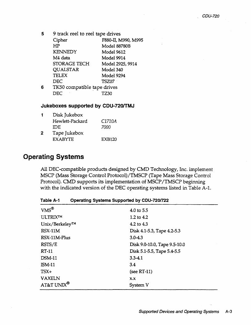
5 9 track reel to reel tape drives Cipher F880-IT,~990,~995
rIP ~odel88780B
KENNEDY ~ode19612
~4 data ~odel 9914 STORAGE TECH ~ode12925, 9914 QUALSTAR ~odel340
TELEX ~odel 9294 DEC TSZ07-
6 TK50 compatible ~ape drives DEC TZ30
Jukeboxes supported by CDU-72orrMJ
1 Disk Jukebox Hewlett-Packard IDE
2 Tape Jukebox EXABYTE
Operating Systems
C1710A 7000
EXB120
CDU-720
All DEC-compatible products designed by CMD Technology, Inc. implement MSCP (Mass Storage Control Protocol)/TMSCP (Tape Mass Storage Control Protocol). CMD supports its implementation of MSCP ITMSCP beginning with the indicated version of the DEC operating systems listed in Table A-I.
Table A-1 Ope~ting Systems Supported by CDU-720n22
VMS® 4.0 to 5.5
ULTRIxrM 1.2 to 4.2
Unix/BerkeleyTM
RSX-11~
RSX-11~-Plus
RSTS/E
RT-l1
DS~-11
IS~-11
TSX+
VAXELN
AT&T~
4.2 to 4.3
Disk 4.1-5.3, Tape 4.2-5.3
3.0-4.3
Disk 9.0-10.0, Tape 9.5-10.0
Disk 5.1-5.5, Tape 5.4-5.5
3.3-4.1
3.4
(see RT-ll)
x.x System V
Supported Devices and Operating Systems A-3

CDU-720
A-4 Supported Devices and Operating Systems

Appendix B Troubleshooting
VMS Analyze/Error Utility
The CDU-720 logs controller dependent information in ERRLOG.SYS file. You can use the VMS ANALYZE/ERROR Utility to open the file ERRLOG.SYS and display the error messages for troubleshooting. By including option switches such as /SINCE=DATE and /INCLUDE=MUBO, you may define the time reference and device. To enter the ANALYZE/ERROR Utility, log onto the system and enter the following command:
anal errl since=[time1Iinclude=[device1
Some examples are shown by the following: To view all errors that VMS has logged, enter:
analerr .
To view the errors only on tape devices, enter:
anal errlinc = tapes
To view the errors that have occured only on one tape unit (MUBO), enter;
anal errlinc=mubo anal errlinc=(ptb,mubo)
To view the MUBO errors that oeeured on April 20, 1990 sinee 14:22 (02:22 PM), enter:
analerrlsince=2O-Apr-1989:14:22linc=tnub0
Troubleshooting 8-1

CDU-720
One example of the error log message is shown in below:
BEGINING OF INTERVENING ENTRIES
ERROR SEQUENCE 9. LOGGED ON SID 0200SF78 ERL$LOG~SSAGE ENTRY 20-APR-1989 10:21:55.41
KA750 REV# 120. UCODE REV# 95. I/O SUB-SYSTEM, UNIT _MUAO: :rvfESSAGE TYPE 0002
MSLG$L_CMD_REF 99730004 MSLG$W _SEQ.NUM 0001
00
TAPE MSCP :rvfESSAGE
SEQUENCE #1.
CONTROLLER ERROR MSLG$B_FLAGS MSLG$W _EVENT 00E8 DATA ERROR
UNRECOVERABLEECCERROR
00340000 03090000
UNIQUE IENTIFIER,' 000000340000 TAPE CLASS DEVICE TKSOP
CONTROLLER SOFTWARE VERSION #1.
CONTROLLER HARDWARE VERSION #1.
8-2 Troubleshooting

CDU-720
Controller Dependent Information: Listed below is the controller dependent information for the CDU-720.
LONGWORD 1.
LONGWORD2.
LONGWORD3.
LONGWORD4.
LONGWORD5.
LONGWORD6.
LONGWORD7.
LONGWORD8.
LONGWORD9.
LONGWORD10
;COMMENTS; ;SCSI COM1v1AND, 6 BYTES
00000008 ;COM1v1AND BYTE 3 TO 0 1 .... 1 ;(LEFf TO RIGHT, BYTE 3,2,1,0)
00000050 ;BYTE 7 TO 6 OONT CARE ;COM1v1AND BYTE 5 TO 4
IP ... I ;EXTENDED SENSE, 26 BYTES 00030070 ;SENSE DATA BYfE 3 TO 0
IP ... I ;(LEFf TO RIGHT, BYTE 3,2,1,0) 12000000 ;SENSE DATA BYTE 7 TO 4
1 .... 1; 00000000 ;SENSE DATA BYTE 11 TO 8
1 .... 1; 00000000 ;SENSE DATA BYTE 15 TO 12
1 .... 1; 10000000 ;SENSE DATA BYTE 19 TO 16
1 .... 1; 04000000 ;SENSE DATA BYTE 23 TO 20
1 .... 1; 0000E202 ;SENSE DATA BYTE 26 TO 24
l.b .. I; 00000000 ;(RESERVED)
1 .... 1;
Refer to the SCSI tape drive manual for a description of the error reported by the tape drive or call CMD for more detailed information.
Cables
If the system does not recognize the CDU-720 or devices connected, check the cable connections. Make sure pin 1 on the cable is aligned with pin 1 on the SCSI device or CDU-720. Make sure pins are NOT bent.
LED Indicators
When the Red LED is lit, turn system /I OFF" and reboot. If the Red LED is still lit, call CMD technical support at (800) 426-3832 or (714) 454-0800.
Troubleshooting 8-3

CDU-720 -
CMD Technical Support
Having a CMD board entitles you to responsive technical support. Before you call CMD Technical Support, please gather the information listed below that pertains to your configuration. Make a note of any on-screen messages when a problem occurs and have this manual close by.
CMD CMD product model number and serial number. Firmware Rev. of CMD board as shown on Eprom on the
CDU-720 with a blue CMD logo and copyright label. Listing of jumper settings on the board. Distributor company and contact.
SCSI SCSI devices model numbers and firmware Rev. as shown in the On-Board Utility.
Settings of SCSI ID numbers of all devices.
Computer Computer model. Operating System version. Complete listing of other. controllers in computer backplane. Specify multi-hosting or clustering.
Problem Describe exact nature of problem. Specify detailed error messages. Specify any recent modification to the system. Is this a new installation? Does the problem occur consistently? Does the problem occur when you ~o not use the board? Does the problem occur with another system (if available)?
You may contact CMD Technical Support from 8:30 AM to 5:30 PM, Pacific Standard Time, Monday through Friday, excluding major holidays, at
8-4 Troubleshooting
(714) 454-0800 or (800) 426-3832 or (714) 455-1656 FAX

Appendix C Jumper Settings
This chapter lists the jumper settings and CSR addresses for the CDU-720.
Pin Assignments
Figure C-l shows the physical pin number assignments of the RS-232 port for accessing the On-Board Utility. Connector J4 pin assignments are listed in Table C-1 shown when you are facing the 10 pin connector from the controller's top edge.
NOTE For CMD's On-Board RS-232 Utility, only pin 3, 8 and grounds are used.
9
Q~~ D 10 2
Rgure C-1: R5-232 Port connector J4
Jumper Settings C-1

CDU-720
Table C-1
Pin 1 2
3 4
5 6 7 8 9
10
Pin Assignments for Utility
RS-232 Port No connect Ground TXD, transmit data for RS-232 application. Ground (use pin 2) No connect No connect No conne~t RXD, receive data for RS-232 application. Ground (use pin 2) No connect
Table C-2 lists the Host Adapter ID selections; Table C-3 lists all the other jumper selections for the CDU-720.
Table C-2 Host Adapter 10 Selections
W6-1 W6-2 W6-3 Initiator ID IN IN IN Host adapter ID .~" 7, highest priority (F)
IN IN OUT Host adapter ID = 6 IN OUT IN Host adapter ID = 5 IN OUT OUT Host adapter ID = 4 OUT IN IN Host adapter ID = 3 OUT IN OUT Host adapter ID = 2 OUT OUT IN Host adapter ID = 1 OUT OUT OUT Host adapter ID = 0, lowest priority
Note (F) means factory setting.
C-2 Jumper Settings

CDU-720
Table <:-3 CDU-720n22 Pin Assignments
WI W2 W2 W3
W3 W4 WS
WS W6-4 W6-4 W6-5
W6-S
W6-6
W6-6 W6-7 W6-7 W7 W7 W9
2-3 IN 2-3 IN 1-2 IN WI0 WI0 W17, W18,W19 W20,W21,W22
W20,W21,W22
IN OUT IN OUT 1-2 IN 1-2 IN
2-3 IN IN OUT IN
OUT
IN OUT IN OUT 1-2 IN 2-3 IN W8
2-3 IN 1-2 IN 1-2 IN 1-2 IN 2-3 IN
1-2 IN
2-3 IN
Note (F) means factory setting.
Reserved (F) Differential SCSI terminator power enabled (F)
Differential SCSI terminator power disabled Single-ended SCSI terminator power enabled (F)
Single-ended SCSI terminator power disabled Reserved (F)
Auto-Boot disabled for CDU-720/M, /TM (F) Reserved for CDU-720/T (F)
Auto-Boot enabled for CDU-720/M, /TM Enable tape fast search option Norma! operation (F)
Tape Monitor Utility enabled (/T, /TM) Disk SCSIformat ON-LINE enabled (/M, /TM)
Tape Monitor Utility disabled (F) Disk SCSIformat ON-LINE disabled (F)
Tape sync. mode disabled Tape sync. mode enabled (F)
Disk sync. mode disabled Disk sync. mode enabled (F)
4 us DMA dwell time for CDU-720/M (F)
2 us DMA dwell time for CDU-720/T, /TM (F)
1 Word per DMA burst CDU-720/T, /TM (F)
2 Word per DMA burst 4 Word per DMA burst CDU-720/M (F)
Bootstrap address = 77300O-CDU-720/M, /TM Bootstrap address = 77100O-CDU-720/M, /TM (F) Reserved (F)
Differential channel enabled; differential SCSI multiple-host protection circuit enabled (F) Single-ended channel enabled; single-ended SCSI multiple-host protection circuit enabled
Jumper Settings C-3

CDU-720
eSR Address Selections
Table C-4lists the 29 disk CSR addresses supported by the CDU-720/M with the IC P72009A in UI02.
Table C-4 CDU-72OJM CSR Addresses (lC P72009A In U102)
Address PDP-II WII WI2 WI3 WI4 WI5 1 17772150 1-2 IN 1-2 IN 1-2 IN 1-2 IN 1-2 IN
2 17760334 1-2 IN 1-2 IN 2-3 IN 1-2 IN 1-2 IN 3· 17760354 1-2 IN 2-3 IN 1-2 IN 1-2 IN 1-2 IN
4 17760374 1-2 IN 2-3 IN 2-3 IN 1-2 IN 1-2 IN
5 17760340 2-3 IN 1-2 IN 1-2 IN 1-2 IN 1-2 IN
6 17760344 2-3 IN 1-2 IN 2-3 IN 1-2 IN 1-2 IN
7 17760350 2-3 IN 2-3 IN 1-2 IN 1-2 IN 1-2 IN
8 17760360 2-3 IN 2-3 IN 2-3 IN 1-2 IN 1-2 IN
9 17760364 1-2 IN 1-2 IN 1-2 IN 2-3 IN 1-2 IN
10 17760370 1-2 IN 1-2 IN 2-3 IN 2-3 IN 1-2 IN
11 17760400 1-2 IN 2-3 IN 1-2 IN 2-3 IN 1-2 IN
12 17760404 1-2 IN 2-3 IN 2-3 IN 2-3 IN 1-2 IN·
13 17760410 2-3 IN 1-2 IN 1-2 IN 2:-3 IN 1-2 IN
14 17760414 2-3 IN 1-2 IN 2-3 IN 2-3 IN 1-2 IN
15 17760420 2-3 IN 2-3 IN 1-2 IN 2-3 IN 1-2 IN
16 17760424 2-3 IN 2-3 IN 2-3 IN 2-3 IN 1-2 IN
17 17760430 1-2 IN 1-2 IN 1-2 IN 1-2 IN 2-3 IN
18 17760434 1-2 IN 1-2 IN 2-3 IN 1-2 IN 2-3 IN
19 17760440 1-2 IN 2-3 IN 1-2 IN 1-2 IN 2-3 IN
20 17760444 1-2 IN 2-3 IN 2-3 IN 1-2 IN 2-3 IN
21 17760450 2-3 IN 1-2 IN 1-2 IN 1-2 IN 2-3 IN
22 17760454 2-3 IN 1-2 IN 2-3 IN 1-2 IN 2-3 IN
23 17760460 2-3 IN 2-3 IN 1-2 IN 1-2 IN 2-3 IN
24 17760464 2-3 IN 2-3 IN 2-3 IN 1-2 IN 2-3 IN
25 17760470 1-2 IN 1-2 IN 1-2 IN 2-3 IN 2-3 IN
26 17760474 1-2 IN 1-2 IN 2-3 IN 2-3 IN 2-3 IN
27 17760500 1-2 IN 2-3 IN 1-2 IN 2-3 IN 2-3 IN
28 17760504 1-2 IN 2-3 IN 2-3 IN 2-3 IN 2-3 IN
29 17760510 2-3 IN 1-2 IN 1-2 IN 2-3 IN 2-3 IN
C-4 Jumper Settings
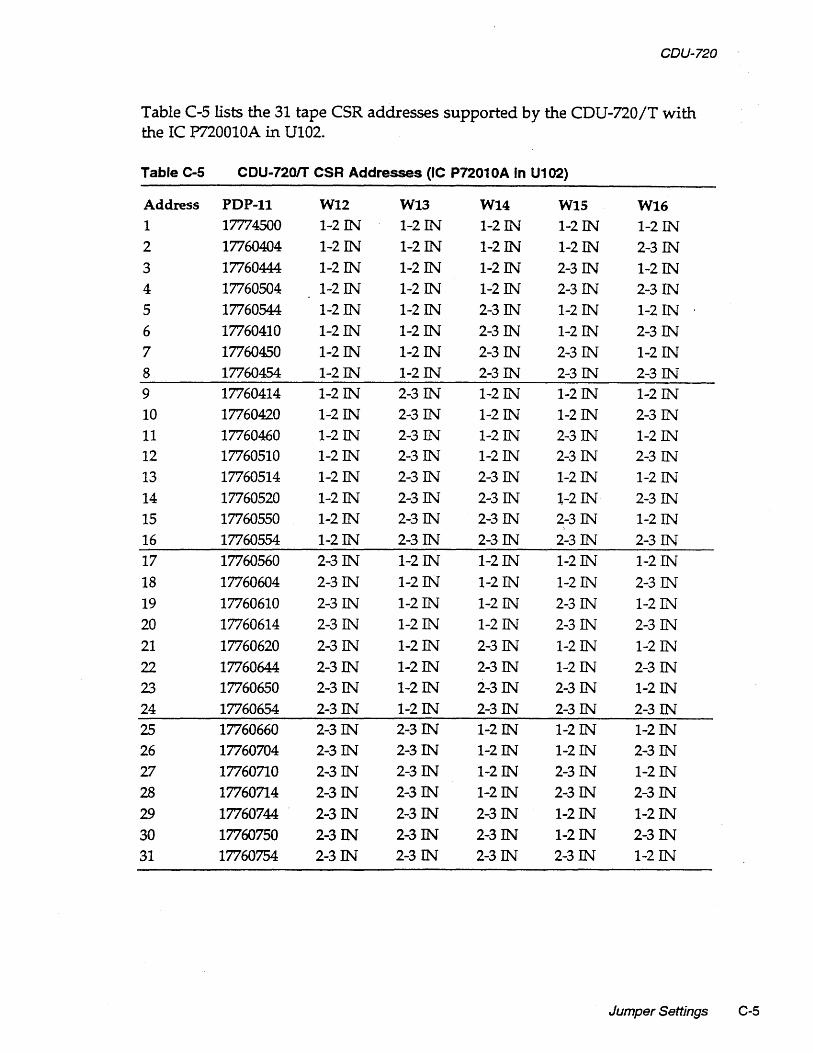
CDU-720
Table C-S lists the 31 tape CSR addresses supported by the CDU-720fT with the IC P720010A in U102.
Table C-5 CDU-7201T CSR Addresses (IC P72010A In U102)
Address PDP-II WI2 WI3 WI4 WI5 WI6 1 17774500 1-2 IN 1-2 IN 1-2 IN 1-2 IN 1-2 IN 2 17760404 1-2 IN 1-2 IN 1-2 IN 1-2 IN 2-3 IN
3 17760444 1-2 IN 1-2 IN 1-2 IN 2-3 IN 1-2 IN 4 17760504 1-2 IN 1-2 IN 1-2 IN 2-3 IN 2-3 IN
5 17760544 1-2 IN 1-2 IN 2-3 IN 1-2 IN 1-2 IN
6 17760410 1-2 IN 1-2 IN 2-3 IN 1-2 IN 2-3 IN
7 17760450 1-2 IN 1-2 IN 2-3 IN 2-3 IN 1-2 IN 8 17760454 1-2 IN 1-2 IN 2-3 IN 2-3 IN 2-3 IN 9 17760414 1-2 IN 2-3 IN 1-2 IN 1-2 IN 1-2 IN 10 17760420 1~2IN 2-3 IN 1-2 IN 1-2 IN 2-3 IN 11 17760460 1-2 IN 2-3 IN 1-2 IN 2-3 IN 1-2 IN 12 17760510 1-2 IN 2-3 IN 1-2 IN 2-3 IN 2-3 IN
13 17760514 1-2 IN 2-3 IN 2-3 IN 1-2 IN 1-2 IN
14 17760520 1-2 IN 2-3 IN 2-3 IN 1-2 IN 2-3 IN
15 17760550 1-2 IN 2-3 IN 2-3 IN 2-3 IN 1-2 IN
16 17760554 1-2 IN 2-3 IN 2-3 IN 2-3 IN 2-3 IN
17 17760560 2-3 IN 1-2 IN 1-2 IN 1-2 IN 1-2 IN
18 17760604 2-3 IN 1-2 IN 1-2 IN 1-2 IN 2-3 IN
19 17760610 2-3 IN 1-2 IN 1-2 IN 2-3 IN 1-2 IN
20 17760614 2-3 IN 1-2 IN 1-2 IN 2-3 IN 2-3 IN
21 17760620 2-3 IN 1-2 IN 2-3 IN 1-2 IN 1-2 IN
22 17760644 2-3 IN 1-2 IN 2-3 IN 1-2 IN 2-3 IN
23 17760650 2-3 IN 1-2 IN 2-3 IN 2-3 IN 1-2 IN
24 17760654 2-3 IN 1-2 IN 2-3 IN 2-3 IN 2-3 IN
25 17760660 2-3 IN 2-3 IN 1-2 IN 1-2 IN 1-2 IN
26 17760704 2-3 IN 2-3 IN 1-2 IN 1-2 IN 2-3 IN
27 17760710 2-3 IN 2-3 IN 1-2 IN 2-3 IN 1-2 IN
28 17760714 2-3 IN 2-3 IN 1-2 IN 2-3 IN 2-3 IN
29 17760744 2-3 IN 2-3 IN 2-3 IN 1-2 IN 1-2 IN
30 17760750 2-3 IN 2-3 IN 2-3 IN 1-2 IN 2-3 IN
31 17760754 2-3 IN 2-3 IN 2-3 IN 2-3 IN 1-2 IN
Jumper Settings C-5

CDU-720
Tables C-6 and C-7listthe eight disk and tape CSR addresses supported by the CDU-720/TM with the IC P720008A in UI02.
Table C-6 CDU .. 720ITM Disk CSR Addresses OC P72008A In U102}
Address PDP-II WII WI2 WI3 1 17772150 (F) 1~2W 1-2W 1-2W 2 17760334 1-2W 1-2 IN 2-3W
3 17760354 1-2W 2-3 IN 1-2W
4 1776031.4 1-2W 2-3 IN 2-3W
5 17760340 2-3 IN 1-2 IN 1-2 IN
6 17760344 2-3 IN 1-2 IN 2-3 IN
7 17760350 2-3 IN 2-3 IN 1-2 IN
8 Disab Ie Disk 2-3 IN 2-3 IN 2-3 IN
Table C-7 CDU-720ITM Tape CSR Addresses (IC P72008A in U102)
Address PDP-II WI4 WI5 WI6 1 17774500 (F) 1-2 IN 1-2 IN 1-2 IN
2 17760404 1-2 IN 1-2 IN 2-3 IN 3 17760444 1-2 IN 2-3 IN 1-2 IN
4 17760504 1-2 IN 2-3 IN 2-3 IN
5 17760544 2-3 IN 1-2 IN 1-2 IN
6 17760410 2-3 IN 1-2 IN 2-3 IN
7 17760450 2-3 IN 2-3 IN 1-2 IN
8 Disable Tape 2-3 IN 2-3 IN 2-3 IN
C-6 Jumper Settings

Appendix D VMS SYSGEN Connect Statement
To properly use the CONNECT statement in the SYSGEN Utility of VMS 5.0 and newer versions, the following rules must be followed.
1 Run the SYSGEN Utility, from either terminal mode or through a command file by entering at the system prompt MC SYSGEN.
It is recommended that you use SYCONFIG.COM if an automatic command file is used. :
2 Issue the CONNECT statement to connect the controller by entering the following line at the SYSGEN prompt:
CONNECT aaaaIADAPTER=bbbICSR=% Occccccccl VECTOR=%OdddJDRIVER=eeDRIVER
Where: aaaa-the designation of the controller (no:) such as PTBO. bbb-the adapter number which can be found from the SYSGEN utility
SHOW/CONFIG (the NEXUS number) in decimal. ccccccce-the CSR of the controller being added on the specified NEXUS
preceeded by %0 (letter 0) in octal. ddd-the VECTOR of the controller being added on the specified NEXUS preceeded by %0 (letter 0) in octal. ee -the name of the driver for the controller being connected.
VMS SYSGEN CONNECT Statement 0-1

CDU-720
3 Issue the next CONNECT statement to connect the drive by entering the following line at the SYSGEN prompt:
CONNECI' ffffINOADAPTERlSYSIDHIGH=%Xggggl SYSIDLOW= %XhhhhhhhhlDRIVER=iiDRIVER
Where: ~ ffff-the designation of the drive (no :) such as MUBO.
gggg-the SYSIDHIGH number which is 8000 plus the NEXUS number. hhhhhhhh-the SYSIDLOW number which can be obtained after the
controller is connected by using the SYSGEN utility SHOW/UNIBUS. The newly attached controller will be seen at the CSR address previously specified followed by the SYSIDLOW number seen in (hhhhhhhh).
[EXAMPLE] you may wish to connect a tape drive to a Micro VAX 3300. This tape drive is the third MU: device to be added to the Q-bus. The AUTOCONNECT recommended CSR for this device will not be used but the CSR of 760444 will be used instead with a VECTOR of 340 on DBO.
3 View the configuration files by entering the following line at the system prompt:
MCSYSGEN SHOWICONFIG
The screen displays the configuration as shown in Figure D-l:
System eSR and Vectors on 11-JAN-1990 10:43:47.59 Name: PUA Units: 1 Nexus:O (USA) eSR: 772150 Vector1 : 774 .. . Name: PTA Units: 1 Nexus:O (USA) eSR: 774500 Vector1 : 260 .. . Name: PUS Units: 1 Nexus:O (USA) eSR: 760334 Vector1 : 300 .. . Name: TXA Units: 8 Nexus:O (USA) eSR: 760500 Vector1 : 310 .. .
Rgure 0-1: SYSGEN Conflg Rle
Note the Nexus number 0 for the specified bus.
D-2 VMS SYSGEN Connect Statement

4 Edit the configuration file to connect the devices by entering the following line at the SYSGEN prompt:
CONNECT PTCO/ADAPTER=UBO/CSR=%07604441 VECTOR=% 034O/DRIVER=PUDRIVER
5 Find the address for the Q-bus by entering SHOW/UNIBUS
Figure 0-2 shows the address:
Address 760444 (8002A924) responds with value 0020 (hex).
Figure 0-2: Unibus Address
6 Note the SYSIDLOW value.
CDU-720
7 Calculate the SYSIDHIGH value by adding 8000 to th.e NEXUS a (which is 8000) and enter the following lines at the SYSGEN prompt
CONNECT MUCO/NOADAPTERlSYSIDillGH=%X8000/ SYSIDL0 W=%X8002A9241DRIVER=Tl!DRIVER
*EXIT* (CONTROL Z to exit)
VMS SYSGEN CONNECT Statement 0-3

CDU-720
0-4 VMS SYSGEN Connect Statement
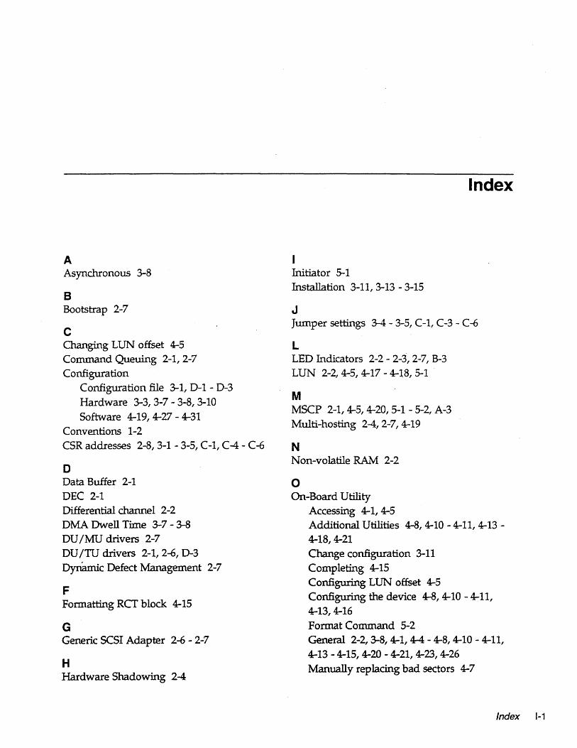
A Asynchronous 3-8
B Bootstrap 2-7
c Changing LUN offset 4-5 Command Queuing 2-1,2-7 Configuration
Configuration file 3-1, D-1 - D-3 Hardware 3-3,3-7 - 3-8,3-10 Software 4-19,4-27 - 4-31
Conventions 1-2 CSR addresses 2-8,3-1 - 3-5, C-1, C-4 - C-6
D Data Buffer 2-1 DEC 2-1 Differential channel 2-2 DMA Dwell Time 3-7 - 3-8 DU /MU drivers 2-7 DU /TU drivers 2-1, 2-6, D-3 Dynamic Defect Management 2-7
F Formatting RCT block 4-15
G Generic SCSI Adapter 2-6 - 2-7
H Hardware Shadowmg 2-4
Index
Wtiator 5-1 Installation 3-11,3-13 - 3-15
J Jumper settings 3-4 - 3-5, C-1, C-3 - C-6
L LED Indicators 2-2 - 2-3, 2-7, B-3 LUN 2-2,4-5,4-17 - 4-l8, 5-1 '
M MSCP 2-1,4-5,4-20,5-1 - 5-2, A-3 Multi-hosting 2-4, 2-7, 4-19
N Non-volatile RAM 2-2
o On-Board Utility
Accessing 4-1, 4-5 Additional Utilities 4-8,4-10 - 4-11,4-13 -4-18,4-21 Change configuration 3-11 Completing 4-15 Configuring LUN offset 4-5 Configuring the device 4-8,4-10 - 4-11, 4-13,4-16 Format Command 5-2 General 2-2, 3-8, 4-1, 4-4 - 4-8, 4-10 - 4-11, 4-13 - 4-15,4-20 - 4-21,4-23,4-26 Manually replacing bad sectors 4-7
Index 1-1

CDU-720
Qualifying the drive 4-6
Operating temperature 2-7
P Partitioning 2-4 Power ON/OFF Protection 3-9
S SCSI Bus 2-1 SCSI bus termination 3-13 - 3-14, 3-16 SCSI cabling 3-13,3-15, B-3 SCSI commands 5-2 SCSI glossary 5-1 SCSI ID 3-11,4-17 - 4-18
Host Adapter 3-11, C-2 Target devices 3-11
SCSI Library Manager 2-4, 2-6 - 2-7 SCSI status codes 5-3 SCSIformat ON-LINE 2-5, 2-7, 3-10
. Sending SCSI commands to the device 4-13 Shadowing 2-5, 2-7 Single-ended channel 2-1 - 2-2 Single-ended mode 4-20 Single-ended signals 5-4 - 5-6 Special Features 2-4 - 2-6 Specifications 2-7
1-2 Index
Supported devices 2-7, A-I - A-3 Supported Operating Systems A-3 Synchronous/AsynChronous ~ SYSGEN Utility 3-1 .. 3-3, D-l - D-3
T Tape Fast Search 3-10 Tape Monitor Utility 2-4 - 2-5, 2-7, 3-10 Target 3-11, 5-2 Technical Support B-4 Terminator power 3-14 Testing SCSI devices 4-14 TMSCP 2-1, 5-1, 5-3, A-3 Troubleshooting B-1 - B-4
U Ultrix 2-1,4-28 - 4-31, A-3 Unibus 2-1 Unit Numbering 4-16 - 4-18 Unix 2-1, A-3
V VAX 2-1 Virtual data buffer 2-7 VMS 2-1,4-21, A-3, D-l VMS Analyze/Error Utility B-1 - B-3

CDU·720 Quick Reference Guide
I. Determining eSR Address
Before you install the COU-720 SCSI host adapter under the VMS operating system you must determine the Control and Status Register (CSR) address from which the COU-720 will be accessed.
For the COU-720/M, or COU-720/T, only one CSR address is required. For the COU-720/TM, two CSR addresses are required. The following procedure shows one method of determining the new CSR address to be used for the COU-720.
Do not Install the new CDU-720 In the system now.
1 Boot the VMS system and log into the system manager account.
2 At the DCL $ prompt, enter me sysgen.
3 At the prompt sysgen, enter showlconfig. The Sysgen Utility will display all the device controllers installed in the system and their corresponding CSR addresses and vecto~. Make a note of this list. .
4 At the prompt sysgen, enter config. This will bring you to the device prompt.
S At the prompt device, enter the following for your COU-720 model [enter all devices on the Unibus, not just the new device being added at present]:
For COU-720/M For COU-720/T For COU-720/TM
where:
enter UDA,X enter mS1, Y enter UDA,X and mSl, Y
X is the number of installed UDA type controllers plus 1 (for new one being added) Y is the number of installed TU81 type controllers plus 1 (for new one being added).
6 At the prompt device, enter [CTRL] + Z. The Sysgen Utility will display Ule CSR addresses for all the controllers. Make sure that no other vectors or CSR addresses have changed; if they have, make the appropriate changes to the devices.
The VMS mnemonic' for MSCP disk controllers are PUA, PUB, PUC; etc. The VMS mnemonic for TMSCP tape controllers are PTA, PTB, PTC, etc. For other mnemonics, refer to VMS system manager's guide.
7 At the prompt sysgen, enter [CTRL] + Z to exit the Sysgen Utility. VMS will automatically program the COU-720's interrupt vector register to match the vector assigned by the system. The vectors of Ule controllers might change when the COU-720 is added to the system; see manufacturer's documentation to configure vectors and device CSR addresses if hardware selectable.
II. eSR Address Selection
Use the CSR address obtained above to configure the CSR jumper seHings of the COU-720. as shown in Tables 1-4. Refer to Appendix C, COU-720 User's Manual for other CSR jumper settings.
Table 1 CDU-7201M CSR Jumper settlngs-dlsk
Add. PDP-lt Wl1 W12 W13 W14 Wts 1 17772 150 (F) 1-2 IN 1-2 IN 1-2 IN 1-2 IN 1-2 IN 2 17760334 1-2 IN 1-2 IN 2-3 IN 1-2 IN 1-2 IN 3 17760354 1-2 IN 2-3 IN 1-2 IN 1-2 IN 1-2 IN 4 17760374 1-2 IN 2-3 IN 2-3 IN 1-2 IN 1-2 IN 5 17760340 . 2-3 IN 1-2 IN 1-2 IN 1-2 IN 1-2 IN 6 17760344 2-3 IN 1-2 IN 2-3 IN 1-2 IN 1-2 IN 7 17760350 2-3 IN 2-3 IN 1-2 IN 1-2 IN 1-2 IN 8 17760360 2-3 IN 2-3 IN 2-3 IN 1-2 IN 1-2 IN
PallC P72009A must be In U102.
Be sure to wear anti-static wrist straps or equiva-lent to protect the eDU-720 from electro-static damage.
Table 2 CDU-720rr eSR Jumper settings-Tape
Add. PDP-ll W12 WU W14 WU W16 1 17774500 (P) 1-2 IN 1-2 IN 1-2 IN 1-2 IN 1-2 IN 2 17760404 1-2 IN 1-2 IN 1-2 IN 1-2 IN 2-3 IN 3 17760444 1-2 IN 1-2 IN 1-2 IN 2-3 IN 1-2 IN 4 17760504 1-2 IN 1-2 IN 1-2 IN 2-3 IN 2-3 IN 5 17760544 1-2 IN 1-2 IN 2-3 IN 1-2 IN 1-2 IN 6 17760410 1-2 IN 1-2 IN 2-3 IN 1-2 IN 2-3 IN 1 17760450 1-2 IN 1-2 IN 2-3 IN 2-3 IN 1-2 IN 8 17760454 1-2 IN 1-2 IN 2-3 IN 2-3 IN 2-3 IN
PallC P72010A muslin U102.
Table 3 CDU-720fTM eSR Jumper settlngs-dlsk
Add. PDP-ll Wl1 W12 W13 1 17772150 (F) 1-2 IN 1-2 IN 1-2 IN 2 17760334 1-2 IN 1-2 IN 2-3 IN 3 17760354 1-2 IN 2-3 IN 1-2 IN 4 17760374 1-2 IN 2-3 IN 2-3 IN 5 17760340 2-3 IN 1-2 IN 1-2 IN 6 17760344 2-3 IN 1-2 IN 2-3 IN 1 17760350 2-3 IN 2-3 IN 1-2 IN 8 Disable Disk 2-3 IN 2-3 IN 2-3 IN
PallC P72008A musl be In U102.
Table 4 CDU-720rrM eSR Jumper settings-tape
Add. PDP-ll W14 W15 W16 1 17774500 (F) 1-2 IN 1-2 IN 1-2 IN 2 17760404 1-2 IN 1-2 IN 2-3 IN 3 17760444 1-2 IN 2-3 IN 1-2 IN 4 17760504 1-2 IN 2-3 IN 2-3 IN 5 17760544 2-3 IN 1-2 IN 1-2 IN 6 17760410 ' 2-3 IN 1-2 IN 2-3 IN 7 17760450 2-3 IN 2-3 IN 1-2 IN 8 Disable Tape 2-3 IN 2-3 IN 2-3 IN
PallC P72008A must be In U102.

III. Installation
1 Configure the hardware as explained in "Hardware Configuration" Chapter 3. [Normally, you do not need to change the factory jumper settings for the CDU-720.] Be sure you have set the CSR addresses as described in sections I and II.
2 Set the Device SCSI ID's; see Table 5 for Device ID Selection. If you are changing the factory settin§ for the CDU-720/TM, refer to Chapter 4, 'Unit Numbering."
Table 5 Device 10 Selection
Model Device Support Target SCSI 10 CQD-240/M up to 7 disk drives SCSIID=O-{i CQD-240/T up to 7 tape drives SCSIID=O-{i CQD-240/TM up to 7 dI8k/ta~ combined SCSI 10=0-3 disks (El
4 disk & 3 tape (F) SCSIIO=4-{i tapes (I')
Note that (F) means factory setllng.
3 Install the CDU-720 into any priority on the standard PDP-II Unibus SPC backplane. The CDU-720 is a DMA device and requires the Non-processor Grant (NPG) jumper on the SPC card slot in which the controller is being installed be removed. Place the CDU-720 in front of other devices on the Unibus except when there is an Ethernet controller. The CDU-720 should be inserted into C, D, E, F sockets of a Unibus slot.
4 The Non-Processor Grant Signal (NPG) signal jumper is located at pins CAl to CDI on the Unibus backplane. Figure 1 is a DDII-DK nine-slot backplane seen from the rear. To locate the NPG jumper follow these instructions: a From the rear of the backplane locate the
card slot in which the board is to be installed. Each card slot is four pins wide.
b Locate the C socket and then locate the pins CA 1 and CD 1. Remove the jumper wire between the two pins as shown in Figure 1.
Unlb~ IN Unbus OUT
A~8 • "" A ""'", C.
·0 ~--:.:.:. ----~---- -------- ---- --- ----
""~""'", B
~""~
E • eF
G.
eH --- ---- ---- --- ----~ ~ --- ----I . c .J
K e
·L M. --- ---- ;-- ---- ---~V ---- ---
~vt:::v 0 ",-VI .-V
eN o.
e ~ v~ v
.p Q.
en ~ --- ---- --- --- ---- --- ---- --- ----~------~ E
Typical Socket
56789
Figure 1: Unibus Wire Wrap 'Slde of Backplane
5 Cable SCSI devices (see "SCSI Bus Cabling," Chapter 3) to Jl for single-ended of the CDU-720 or J2 differential of the CDU-722, see Figures 2 and 3.
Figure 2: COU-722 J1 and J2 SCSI ports
Figure 3: SCSI 10 and Cabling
6 Terminate the SCSI bus at each physical end. If the CDU-720 is at one physical end of the bus, place terminators as shown in Table 6.
Table 6 Terminator Power Option
RNI, RN2, Btll- RN4, IN RN5, RN6, KN/, RN8 RNI, RN2, Btl~ RN4, OUT RNS, RN6, KN/, RN8
Differential Mode Termination
NO Differential Termination
RN9, RNIO, RN14 IN Single-ended Mode Termination RN9, RNIO, RNI4 OUT NO Single-ended Termination
Note that (F) means factory &eRlng.
If TERMPWR is needed for the bus, place jumper shunt on W2 for differential or W3 for single-ended as shown in Table 7.
Table 7 Terminator Power Option
W2 IN Differential SCSI terminator power enabled (F) W2 OUT Differential SCSI terminator power disabled W3 IN Slngle-ended SCSI terminator power enabled (P) W3 OUT Single-ended SCSI terminator power disabled
Note that (F) means factory 8etllng.
7 Power up the system and execute On-Board Utility to scan for the SCSI devices and assure that all devices are seen and functioning properly (see Chapter 4 for On-Board Utility).
8 Boot the system and test with the operating system.
CMD TECHNOlOGY, INC. 1 Vanderbnt,lrvlne CA 92718
(714) 454-0800, (800) 428-3832, FAX (714) 455-1858, C CopyrIght CMO, December 1991

I 1-----
If you wish to contact CM D Technology for any reason concerning CMD Warranty Service, please call at (714) 454-0800 or send a letter to: .
CMD Technology, Inc. Customer Service Department 1 Vanderbilt Irvine, CA 92718
Product, __________________________________________ _
Model Number ____________________________ ___
Serial Number __________________ ,Rev. _____ _
Purchase Date ____________________________ ___
Purchased From (Dealer) ______________________________ _
Please retain proof of purchase/sales receipt to verify CMD Warranty.
BUSINESS REPL V MAIL FIRST CLASS MAIL PERMIT NO. 10814 IRVINE, CA
POSTAGE WILL BE PAID BY ADDRESSEE
Customer Service Dept. 1 Vanderbilt Irvine, CA 92718-9714
11111111 11111111111 r " 1111111,,111 " III " III 11111111
NO POSTAGE NECESSARY IF MAILED IN THE UNITED STATES

WARRANTY REGISTRATION CARD The warranty on your CMD computer products and/or software is activated when the questions on this card have been filled out completely and this card has been received by CMD.
Product_~ ______ ~Model Number ______ _ Serial Number ________ Rev. __
Identification (please provide company information if the system was purchased for your work place.)
yourname ____________________ _ Title ______________ _
Company ____________________ _ Dept. _____________ _
Adill~s _____________________________________ _
City _______________________ _ StatelProvince __________ _
Country _____________________ _ Day time phone _________ ___
Authorized Reseller ________________ _ Purchase date __________ _
What prompted you to buy CMD products?
o Advertisement Magazine _______ _ o Dealer Recommendation
o Article Magazine _______ _ o Referral
o CMD Competitive Price o CMD Quality Name Recognition
What computer did you purchase the product for? _______________________ _