Intelligent twin rotor induction motor drive system for ... · Intelligent twin rotor induction...
8
Intelligent twin rotor induction motor drive system for electric and hybrid vehi- cles with random modulation techniques and with fixed switching frequency Zygmunt Szymański Institute of Electrical Engineering and Automation in Mines Silesian University of Technology 44-100 Gliwice, str. Akademicka 2, Poland phone: +48322371688, fax: +48322371537, email : [email protected] Abstract. The paper presents a survey of the wheel vehi- cles with electric and hybrid drive system. A theoretical analy- sis of the wheel hybrid vehicle drive system consisting of: a petrol motor cooperating with two induction motors, fed by transistor voltage inverter based on Intelligent Power Module (IPM), is presented in the paper. An alternating solution of the two induction motor drive system is application of twin rotor induction motor TRIM in a hybrid wheel vehicles. An original machine TRIM has a single stator and two rotors. Each core being disc geometry, with stator sandwiched between two ro- tors. The rotors carry squirrel cage windings, and are mounted on individual, independent shaft, driving two wheels of an electric part of vehicles. The mathematical model of the TRIM supplied with IPM inverter with random modulation technique is described in the paper. The techniques are based on adjust- ing the duration of the zero vectors or adjusting the three pulse positions in the switching period. The new method control of induction motor in hybrid vehicles are also compared with random switching frequency modulation and with fixed switching frequency modulation. Some variants of the adap- tive control system: speed and current adaptive control system and also sliding adaptive control system are applied in the wheel hybrid vehicles. Some results of the computer simula- tions performed for mathematical model of the hybrid drive system for specifically work states: start of the electric motor, electrical braking down to stand still, of the hybrid drive sys- tem are presented in the paper. Voltage, current and acoustic noise spectra are used for comparison parameters. Control method proposed in the paper can substitute classic random modulation techniques with variable switching frequencies in application in electric and hybrid drive system. Key words twin rotor motor, hybrid vehicle, electric vehicle, ran- dom modulation technique 1. Introduction Clean air legislation is impelling advancements and promises for improvement in electric or hybrid machines performance, drive systems and control [4, 10]. Special- ly designed electric machines (induction or permanent magnet motor) have been usually employed in electric vehicles (EVs) or hybrid vehicles (HVs) applications, aiming optimization of efficiency, weight, volume and wider range control [4, 9, 10, 11]. Investigation of di- rect-drive high torque wheel-motor have been done in electric and hybrid vehicles and solar powered cars [4, 9, 10], indicating several advantages as elimination of transmission and gearing losses, better power train trans- mission, fault tolerance improvements and fewer suspen- sion struts requirements. Wheel motor can be used in city cars, electric and hybrid mini vehicles and in spe- cials vehicles. Electric and hybrid vehicles have attract- ed great interests as a powerful solution against environ- mental and energy problems. With improvement of mo- tor and batteries, some pure electric vehicle with only secondary batteries has already achieved enough perfor- mance. Application of the fuel cell will be possibly in a major vehicle in the years: (2003-2008). Modern drive system of road traction vehicles should ensure: environ- mental safety, high reliability and economical speed con- trol in specific duty circumstances. A significant im- provement in economical and power indexes can be achieved by: application of new design drive motors (en- ergy-sparing induction motor, permanent magnet motor, or hybrid drive system which contained petrol and elec- tric motor), application of modern voltage converters controlled by microprocessor systems and optimum con- trol of machines and electric vehicles. Wheels vehicle are usually fitted with petrol motor. However, due to the progress in power and information electronics, the ro- bust induction motor drive and permanent magnet motor drives has become an attractive solution for this applica- tion since there are no need for commutator, switching devices, contactors and others parts subject to wear as necessary in DC series motor and petrol motor. Contact less changing of the direction is simply performed by electronic reverse of the phase-sequence. The highly dy- namic motor control system based on field orientation guaranteed optimal driving comfort through smooth tractive effort and electrical braking down to standstill. The paper present a survey on electric vehicle control system consisting of energy-saving induction motor, fed by transistor voltage converter based on Intelligent Pow- https://doi.org/10.24084/repqj02.316 488 RE&PQJ, Vol. 1, No.2, April 2004
-
Upload
truongcong -
Category
Documents
-
view
245 -
download
18
Transcript of Intelligent twin rotor induction motor drive system for ... · Intelligent twin rotor induction...
Intelligent twin rotor induction motor drive system for electric and hybrid vehi-cles with random modulation techniques and with fixed switching frequency
Zygmunt Szymański
Institute of Electrical Engineering and Automation in MinesSilesian University of Technology
44-100 Gliwice, str. Akademicka 2, Polandphone: +48322371688, fax: +48322371537, email: [email protected]
Abstract. The paper presents a survey of the wheel vehi-cles with electric and hybrid drive system. A theoretical analy-sis of the wheel hybrid vehicle drive system consisting of: apetrol motor cooperating with two induction motors, fed bytransistor voltage inverter based on Intelligent Power Module(IPM), is presented in the paper. An alternating solution of thetwo induction motor drive system is application of twin rotorinduction motor TRIM in a hybrid wheel vehicles. An originalmachine TRIM has a single stator and two rotors. Each corebeing disc geometry, with stator sandwiched between two ro-tors. The rotors carry squirrel cage windings, and are mountedon individual, independent shaft, driving two wheels of anelectric part of vehicles. The mathematical model of the TRIMsupplied with IPM inverter with random modulation techniqueis described in the paper. The techniques are based on adjust-ing the duration of the zero vectors or adjusting the three pulsepositions in the switching period. The new method control ofinduction motor in hybrid vehicles are also compared withrandom switching frequency modulation and with fixedswitching frequency modulation. Some variants of the adap-tive control system: speed and current adaptive control systemand also sliding adaptive control system are applied in thewheel hybrid vehicles. Some results of the computer simula-tions performed for mathematical model of the hybrid drivesystem for specifically work states: start of the electric motor,electrical braking down to stand still, of the hybrid drive sys-tem are presented in the paper. Voltage, current and acousticnoise spectra are used for comparison parameters. Controlmethod proposed in the paper can substitute classic randommodulation techniques with variable switching frequencies inapplication in electric and hybrid drive system.
Key words
twin rotor motor, hybrid vehicle, electric vehicle, ran-dom modulation technique
1. Introduction
Clean air legislation is impelling advancements andpromises for improvement in electric or hybrid machinesperformance, drive systems and control [4, 10]. Special-ly designed electric machines (induction or permanentmagnet motor) have been usually employed in electric
vehicles (EVs) or hybrid vehicles (HVs) applications,aiming optimization of efficiency, weight, volume andwider range control [4, 9, 10, 11]. Investigation of di-rect-drive high torque wheel-motor have been done inelectric and hybrid vehicles and solar powered cars [4,9, 10], indicating several advantages as elimination oftransmission and gearing losses, better power train trans-mission, fault tolerance improvements and fewer suspen-sion struts requirements. Wheel motor can be used incity cars, electric and hybrid mini vehicles and in spe-cials vehicles. Electric and hybrid vehicles have attract-ed great interests as a powerful solution against environ-mental and energy problems. With improvement of mo-tor and batteries, some pure electric vehicle with onlysecondary batteries has already achieved enough perfor-mance. Application of the fuel cell will be possibly in amajor vehicle in the years: (2003-2008). Modern drivesystem of road traction vehicles should ensure: environ-mental safety, high reliability and economical speed con-trol in specific duty circumstances. A significant im-provement in economical and power indexes can beachieved by: application of new design drive motors (en-ergy-sparing induction motor, permanent magnet motor,or hybrid drive system which contained petrol and elec-tric motor), application of modern voltage converterscontrolled by microprocessor systems and optimum con-trol of machines and electric vehicles. Wheels vehicleare usually fitted with petrol motor. However, due to theprogress in power and information electronics, the ro-bust induction motor drive and permanent magnet motordrives has become an attractive solution for this applica-tion since there are no need for commutator, switchingdevices, contactors and others parts subject to wear asnecessary in DC series motor and petrol motor. Contactless changing of the direction is simply performed byelectronic reverse of the phase-sequence. The highly dy-namic motor control system based on field orientationguaranteed optimal driving comfort through smoothtractive effort and electrical braking down to standstill.The paper present a survey on electric vehicle controlsystem consisting of energy-saving induction motor, fedby transistor voltage converter based on Intelligent Pow-
https://doi.org/10.24084/repqj02.316 488 RE&PQJ, Vol. 1, No.2, April 2004
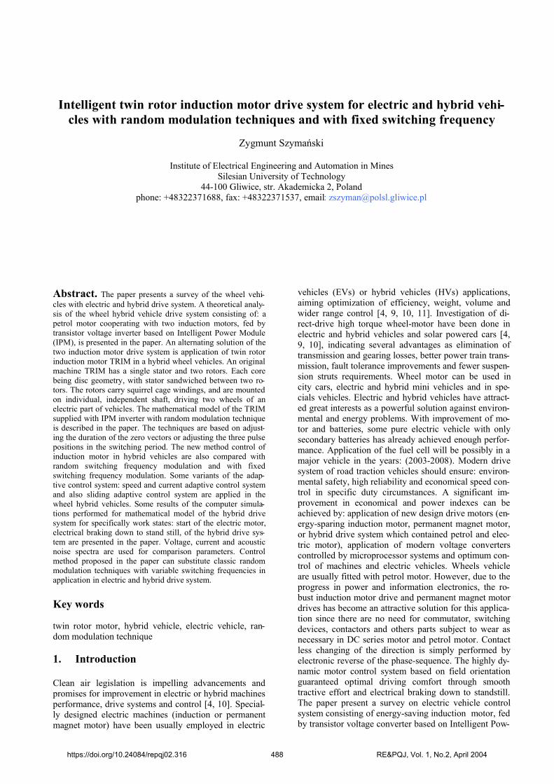
er Module (IPM) and controlled by single chip micro-controller. The paper present also a survey on hybrid ve-hicle consisting of petrol motor and twin rotor, energy-saving, induction motors (TRIM), fed by transistor volt-age converter based on IPM. The implementation offield oriented control, adaptive and sliding mode controlare analyzed in this paper.
Fig.1 Drive system of the wheel vehicle
Although the dynamic performance of a FOC and DTCdrive control is excellent, problems occur in the lowspeed region. The paper show how improved operationat low speed can be achieved using a sliding mode con-trol scheme. Drive system of the hybrid wheel vehicleare presented in fig.1. The mathematical model of theTRIM supplied with IPM inverter with random modula-tion technique is described in the paper. The techniquesare based on adjusting the duration of the zero vectors oradjusting the three pulse positions in the switching peri-od. The new method control of induction motor in hy-brid vehicles are also compared with random switchingfrequency modulation and with fixed switching frequen-cy modulation. Some variants of the adaptive controlsystem: speed and current adaptive control system andalso sliding adaptive control system are applied in thewheel hybrid vehicles. Adaptive controller is realizedbased on DSP controller. Modern controller realized ofrandom modulation techniques are also based on DSPcontroller. The highly dynamic motor control systembased on DSP controller should assured: energy-savingwork system, optimal control of the benzin and electricmotors, and realization of the local and global diagnos-tics procedures and monitoring procedures of the wheelhybrid vehicles. Some results of the computer simula-tions performed for mathematical model of the hybriddrive system for specifically work states: start of theelectric, electrical braking down to stand still, of the hy-brid drive system are presented in the paper. Voltage,current and acoustic noise spectra are used for compari-son and it’s concluded that two of techniques are espe-cially useful at lower fundamental frequencies. Controlmethod proposed in the paper can substitute classic ran-dom modulation techniques with variable switching fre-quencies in application in electric and hybrid drive sys-tem. Some results of numerical calculation of the TRIMmotor drive system was verified of the laboratory exper-iments performed for laboratory model of the hybridwheel vehicles Some results of computer simulationsperformed for mathematical model of vehicles are pre-sented in the paper.
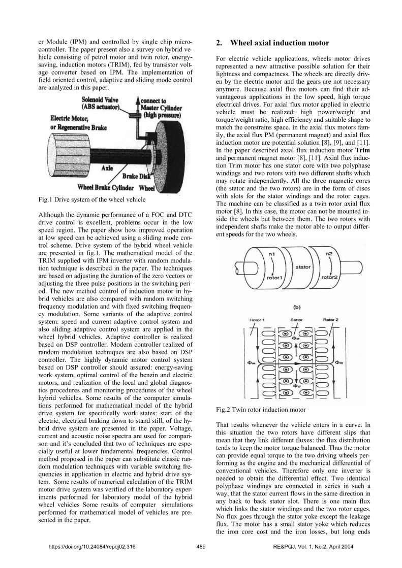
2. Wheel axial induction motor
For electric vehicle applications, wheels motor drivesrepresented a new attractive possible solution for theirlightness and compactness. The wheels are directly driv-en by the electric motor and the gears are not necessaryanymore. Because axial flux motors can find their ad-vantageous applications in the low speed, high torqueelectrical drives. For axial flux motor applied in electricvehicle must be realized: high power/weight andtorque/weight ratio, high efficiency and suitable shape tomatch the constrains space. In the axial flux motors fam-ily, the axial flux PM (permanent magnet) and axial fluxinduction motor are potential solution [8], [9], and [11].In the paper described axial flux induction motor Trimand permanent magnet motor [8], [11]. Axial flux induc-tion Trim motor has one stator core with two polyphasewindings and two rotors with two different shafts whichmay rotate independently. All the three magnetic cores(the stator and the two rotors) are in the form of discswith slots for the stator windings and the rotor cages.The machine can be classified as a twin rotor axial fluxmotor [8]. In this case, the motor can not be mounted in-side the wheels but between them. The two rotors withindependent shafts make the motor able to output differ-ent speeds for the two wheels.
Fig.2 Twin rotor induction motor
That results whenever the vehicle enters in a curve. Inthis situation the two rotors have different slips thatmean that they link different fluxes: the flux distributiontends to keep the motor torque balanced. Thus the motorcan provide equal torque to the two driving wheels per-forming as the engine and the mechanical differential ofconventional vehicles. Therefore only one inverter isneeded to obtain the differential effect. Two identicalpolyphase windings are connected in series in such away, that the stator current flows in the same direction inany back to back stator slot. There is one main fluxwhich links the stator windings and the two rotor cages.No flux goes through the stator yoke except the leakageflux. The motor has a small stator yoke which reducesthe iron core cost and the iron losses, but long ends
https://doi.org/10.24084/repqj02.316 489 RE&PQJ, Vol. 1, No.2, April 2004
windings which results in copper losses. This motor canbe designed as single-phase or as three-phase.
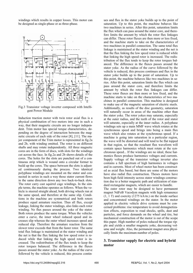
Fig.3 Transistor voltage inverter composed with Intelli-gent Power Module
Induction traction motor with twin rotor axial flux is aphysical combination of two motors into one in such away, that their magnetic circuits are no longer indepen-dent. Trim motor has special torque characteristics, de-pending on the degree of interaction between the mag-netic circuits of each side of the rotor [8], [11]. The ma-jor component of the Trim motor is represented in fig.2aand 2b, with winding omitted. The rotor is on differentshafts and may rotate independently. All three magneticcores are in the form of discs, with slots for the windingscut across the face. In fig.2a and 2b shows details of thecores. The holes for the slots are punched out of a con-tinuous strip which is wound onto a circular former tobuild up the cores. The space between the slots is adjust-ed continuously during the process. Two identicalpolyphase windings are mounted on the stator and con-nected in series in such a way those stator current flowsin the same direction down any two back-to-back slots.The rotor carry cast squirrel cage windings. In the sim-ple terms, the machine operates as follows. When the ve-hicle is steered straight ahead, both driving wheels run atthe same speed, and therefore at the same slip. Condi-tions in the machine are symmetrical and both rotorsproduce equal armature reaction. Thus all flux, exceptleakage, linking the stator windings, also links each rotorwinding. No flux passes around the yoke of the stator.Both rotors produce the same torque. When the vehiclesenter a curve, the inner wheel reduced speed and in-creases slip whereas the outer wheel increases speed andreduced slip. Therefore the armature reaction from theslower rotor exceeds that from the faster rotor. The sametotal flux linkage is maintained at the stator winding andthe net is that the flux linking the low speed rotor is re-duced while that linking the high speed rotor is in-creased. The redistribution of the flux tends to keep therotor torques balanced. The difference in the fluxespasses around the stator yoke. As the radius of the curvefollowed by the vehicle is reduced, this process contin-
ues and flux in the stator yoke builds up to the point ofsaturation. Up to this point, the machine behaves liketwo machines in series. After this point, saturation limitsthe flux which can pass around the stator core, and there-fore limits the amount by which the rotor flux linkagescan differ. These rotor fluxes are then more or less fixed,and the machine starts to take on the characteristics oftwo machines in parallel connection. The same total fluxlinkage is maintained at the stator winding and the net isthat the flux linking the low speed rotor is reduced whilethat linking the high speed rotor is increased. The redis-tribution of the flux tends to keep the rotor torques bal-anced. The difference in the fluxes passes around thestator yoke. As the radius of the curve followed by thevehicle is reduced, this process continues and flux in thestator yoke builds up to the point of saturation. Up tothis point, the machine behaves like two machines in se-ries. After this point, saturation limits the flux which canpass around the stator core, and therefore limits theamount by which the rotor flux linkages can differ.These rotor fluxes are then more or less fixed, and themachine starts to take on the characteristics of two ma-chines in parallel connection. This machine is designedto make use of the magnetic saturation of electric steels.Additionally, as results of the disc geometry, saturationwill naturally occur in areas of the machine other thanthe stator yoke. The rotor yokes may saturate, especiallyat the outer radius, and the teeth of the rotor and statorwill saturate, especially at the inner radius. A polyphasewindings sets up a main MMF wave which rotates at thesynchronous speed and brings into being a main fluxwave which also rotates at the synchronous speed. If amachine is going into saturation in a particular region,the wave will be distorted and will tend to be flat toppedin that region, so that the resultant flux waveform willcontain space harmonics which must rotate at the syn-chronous speed... If the windings are no ideal, these har-monics fluxes produce harmonics voltages and currents.Supply voltage of the transistor voltage inverter alsocontains a full spectrum of high harmonics in voltagesand in currents. Most of wheel motor has been construct-ed as axial flux based, but there are some of the motorshave also radial flux construction. Theses motors havebeen high field intensity across stator windings construc-tion due to a better magnetic path and utilization of stan-dard rectangular magnets, which are easier to handle. The outer rotor may be designed to have permanentmagnet NdFeB Vacodym magnets with high remanence(1, 1 T) and coercity (1275 kA/m.) on the inside surfaceand concentrated windings on the stator. In the motorapplied in electric vehicle drive systems must be con-cerned problems: rise temperature to avoid demagnetiza-tion effects, exposition to road shocks, spills, dust andparticles, and force demands on the wheel and tire, butmechanical construction of the motor is out of the scopethis paper. High number of poles reduced the torque rip-ple and yields a smaller magnetic yoke, decreasing vol-ume and weight. Also, the permanent magnet area physi-cally limits the maximum number of poles.
3. Transistor supply for electric and hybridmotor
https://doi.org/10.24084/repqj02.316 490 RE&PQJ, Vol. 1, No.2, April 2004
Electric vehicle are driven by petrol motor or by electricmotor. IGBT transistors or Intelligent Power Modules(IPM) voltage inverters or three-phase pulse width mod-ulation AC chopper can be used for drive supply system.Fig.3 presents voltage inverter circuit with IPM and 16-bit microcontroller. IPM structure contains IGBT tran-sistor circuit with diodes, transistor gate driver supply,overload, short circuit, thermal and under voltage pro-tection circuits and pulse braking circuit. 16-bit micro-controllers with 32-bit arithmetic, HSO, HSI and PTScircuits can be used for IPM control. Control circuit canensure: wide frequency range close to sinusoidal voltageand currents, complex motor control algorithms (vectorcontrol, direct control and sliding mode control), failurestate detection, analog signal (voltage, current, rotationaland linear speed) measurement, position, speed and ac-celeration feedback) [9, 10]. The high inverter switchingfrequency guaranteed low noise and a good currentwaveform (small losses due to current harmonics). Forloading the inverter DC link, a battery current-limitingloading resistor is used. Some sensor elements give in-formation about actual state of system. Two transform-shunts yield actual phase current control and over cur-rent protection. A digital encoder (250 pulses per revo-lution are sufficient) can be applied for speed measure-ment. A control electronic consist of: 16-bit microcon-troller Siemens production, digital signal processing sys-tem-single ADSP 2101 or TMS 320C25 processor boardperforming some control task and communicating withI/O units.. For control strategy based on field orientedinduction motor control, flux calculation based on twoflux models are combined. In the lower speed range, anindirect current models is used, in the higher speedrange, a voltage model calculates the flux and the cur-rent model is used for motor model adaptation. The in-verter switching frequency is 6 to 9 kHz, depending onthe operation point. Main part of the control unit is thesignal processing system (DSP), for highly dynamictraction control via field orientation and for user specificcontrol tasks (I/O control, driver information, start-upsequence, reference torque generator, battery manage-ment, emergency operation and others). These softwaretools are programmed and presented in graphical moni-tors some diagnostics and monitoring procedures are de-scribed in [9, 10]. The Input/Output unit (SSP) providesthe analog and digital hardware interface. The driverunit (TRP) generates the gate drive signals for the powerIGBTs. The serial RS 485 link is used for real time opti-mization of the drive behavior. All analog and digital in-puts and outputs can be monitored on a laptop PC inreal-time or changed, respectively.
4. Vehicle drive control system
The paper present three control method of induction mo-tor drive system: field oriented method), adaptive con-trol method and sliding mode control method [3], [4],[5], [6], and [7]. In adaptive control method of inductiondrive system is performed a mathematical analysis ofwheel vehicle drive system droved trim induction motorand two single induction motors. System of differentialequations described a dynamic state of the induction mo-tor with one rotor are presented by (1):
d
dtd
dt
d
dt s
d
dt s
ddt J
pJ
p
s
s r s
s
s
s
s r ss
s
s
r
s
s r
s
r
s
s
r
s
s r
s
r
s
s
r
ss r
s
s r
s
M
eM
S
K u
K u
K u
K up KL T
T L
32
3
2
2
L L LR Ms r
s
s r
s
2
(1)
where:
SM
SR
M
R
M
S R
S
S
R
RK L
L K LL
LL L
RL
RL , , , , ,
1
2
System of differential equations described a dynamicstate of the induction motor with one rotor are presentedby (2):
222
2212
111
111
22,2
2
11,1
1
12,1,2
22
22222
22,1,1
11
11111
22,
11,
MM
MoM
MM
MobM
rrsM
TsM
rrsM
TsM
rrr
ssr
rr
rrrsrr
rrr
ssr
rr
rrrsrr
rrs
rrs
ss
sssss
Ddt
dJMM
Ddt
dJMM
iMiM
iMiM
dtdi
Mdtdi
Mdt
diL
dtdi
LiRu
dtdiM
dtdiM
dtdiL
dtdiLiRu
dtdi
Mdt
diM
dtdi
Ldtdi
LiRu
(2)
(State observer defined for fixed coordinate 99 in in-duction motor vector control without rotational speed
sensor, for magnetic flux connected with rotor windingmay be presented in the form of equation (3):
iiIuILJITIT
LJITTT
LITTrs
sS
RR
M
RRS
M
RSK
xxdtd
00
1
1
111^
^
^
^
(3)
where:
https://doi.org/10.24084/repqj02.316 491 RE&PQJ, Vol. 1, No.2, April 2004
x s s s s
T
i i
^^ ^ ^ ^
, , s
Tu u us s ;
I
1 00 1
; J
0 11 0
where estimative angle 1^ of the magnetic field vectorlocation connected with rotor windings for transforma-tion system of variables αβ is equal: ρ=arctg{Ѱrα/ Ѱrβ.On the ground of analysis global stability of drive sys-tem with state observer applied of the research Lapunowfunction method calculate a variability section of correc-tion feedback K0. [3, 4, 5]. Adaptive algorithm of mo-
tor speed 1^ with adaptive period Ta can be done in dis-crete forms by equation system (4):
n n i a n
n n P n
K TK
1
1 1
* *
^ * (4)
where Ki and KP >0. Adaptive error can be calculated with relation (5):
^^^^
rssrss iiii
(5)
In the sliding mode controller of electric vehicle allproblems in the low speed region are caused by use ofinactive or zero vectors of the inverter. Therefore a pos-sible solution would be to avoid using these zero vec-tors, but this leads to a high inverter switching frequen-cy. However, if the inactive voltage vectors are only re-moved in transient conditions, it is possible to achievetorque and flux control, even in the low speed regionwhile lowering the switching frequency in steady-state.For the transient conditions the switching scheme isbased on sliding mode control. The equivalent control isdefined as the input which zeroes derivatives of slidingmode. For stator flux and torque control are selected as(6):
TTSS obcesws
x y /, (6)
To find the equivalent control Vseq the derivatives of (6)are taken:
TTSS obceyswsx
^^^
/,^
(7)
Supposing that the set values for torque and stator fluxare constant, these equations are simplified:
TSS eysx^
/
^^
^
(8)
With the machine equation rewritten in a referenceframe fixed to stator flux these equation become:
IINS
SxfV
syzssyzspy
xzszs
^
,,/
^1,,
^
23
^
(9)
with f1(x) and f2(x) nonlinear function of the motor statex. [3, 4, 5, 6].In the field oriented method digital signal processor(ADSP or TMS320C25) performed all task of controlelectronic and drive system. A slow task (20ms) carriesout interface and communication functions (break andgas pedal, driver interface); a medium task (0,7ms) cal-culates the motor control algorithms, yielding stator-ori-ented reference current components according to thefield-oriented control structure. A fast (45s) currentcontrol task calculates directly inverter switching com-mand [3, 5, 9]. At low speed of motor, a rotor frequencyfeed-forward control is used, at higher speed includingfield-weakening range the slip control is coupled with avoltage model for flux detection. This EMF based fluxinformation is used to adapt the temperature-dependentrotor resistance to its actual value [3], [5], [6], [7]. If themachine is operated below about 35% of base speed(20km/h vehicle speed), no EMF information is utilizedfor control. Hence, rotor resistance adaptation is inactiveand the last value is stored and used until next high-speed operation. In this speed range, the rotor flux refer-ence value is defined constant (rated magnetization). Thetorque command is generated by a driver via gas andbrake pedal signals (considering limitation, rise time bysuperimposed drive control). The mentioned currentcomponents define the reference space phasor of the sta-tor current in a field oriented (x, y) reference frame.Hence, the space phasor has to be transformed into sta-tor- oriented (,) coordinates. The transformation angleis in angular position of the rotor flux space phasor R.The main problem of field -orientation control method isto find accurate field information. In the low speedrange, the reference flux angle ,ref calculated by inte-gration of the reference rotor flux angular velocity ,ref,is used for transformation. Its speed is obtained from ref-erence values of iSy and rotor flux magnitude R and mea-sured rotor angular velocity m. Since no auxiliary in-formation for adaptation of the rotor resistance is avail-able in the low-speed region, the rotor resistance is keptconstant until next high-speed operating point. Returningback from high speed to low speed, the rotor resistanceis fixed at the lst adapted value. However, since the du-ration of low speed operation is relatively short (vehiclespeed below 20km/h), the change of rotor resistance dur-ing this operation can usually be neglected. This controlmethod is described in [3], [5],[9].
5. Random modulation technique with fixedswitching frequency for Trim inductionmotor
Adjustable speed drives have reached a state, where theyhave became armature component in much professionalapplication, particularly in the wheel vehicles. The mainreasons are their capabilities of energy savings, im-
https://doi.org/10.24084/repqj02.316 492 RE&PQJ, Vol. 1, No.2, April 2004
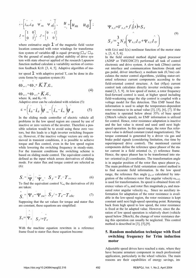
proved automation performance, and also the cost issteadily decreasing. Sensor less control, power converterdesign and pulse width modulation PWM is importantfor the wheel vehicles drive performance in respect tocurrent harmonics, torque ripple, and also acousticnoise, emitted from: induction motor and supply system[1, 2]. Different approaches are used in PWM includingswitching with lower frequency [1, 2], switching withhigh frequency (greater than 17 kHz) [1, 2, 9], or using arandom switching frequency - RSF [1, 2, 9].
Fig.4 Different fixed switching frequency modulationscheme
The method RSF is very efficacious, because the aver-age switching frequency can be kept low as can theacoustic annoyance [2, 4]. One approach uses the spacevector modulation technique extended with a variableswitching frequency operation, which effectively re-duces the acoustic annoyance, but problems arise in thecontrol system because then a variable sampling fre-quency in the controller are needed if the modulator andthe controller shall operate in synchronism [2]. Anothermethod shifts randomly between lagging and leadingedge modulation [1], which effectively gives a randommodulation but problems appear in the sampling of thecurrents without using any anti-aliasing filter. The origi-nal new method RSF presented in the paper operating ata fixed switching frequency, but the pulses are randomlypositioned within the switching period. In that method israndomly changes the duration of zero vectors: 111 and000 [1, 2]. RSF method is applicable to power convert-er, which supplying of the traction motors in wheel vehi-cles, without any neutral connection. All random PWMtechniques have common property that the switching fre-
quency is constant. As stated above this may ease theimplementation of digital controllers, which often aresynchronized to the switching of the inverter, which inturn is controlled by the PWM unit. Having excluded theswitching frequency as the parameter to randomize, itseems that the pulse position is the only quantity whichcan be randomized, while still keeping the average volt-age produced by the inverter fully controllable withineach switching interval. The fundamental idea behindrandom pulse position techniques is that the mean volt-age measured across one switching interval is indepen-dent of the position of the pulse. This degree-of-freedommay be utilized in various ways: from a theoretical pointof view, the only constraint is that a pulse must not ex-tend beyond the boundaries of the switching interval inquestion. That constraint may be met in a number of dif-ferent ways, but the literature dealing with random pulseposition has focused almost exclusively on one simplevariant, namely the so-called lead-lag random pulse po-sition technique originating from [6]. Sketches of the in-vestigated method are show in fig.4 including themethod of [6]. The symbols: qa, qb, qc, indicates thePWM switching function for the three phases, and T isthe switching period. Method RLL (Random Lead–LagModulation- fig.4a): the pulse position is either com-mencing at the beginning of the switching interval, or istailing edge is aligned with the end of the interval. Thechoice between leading and lagging modulation is con-trolled by a random number generator. Method RCD(Random Displacement of the Pulse Center-fig.4b):show a method where the pulses are mutually center-aligned as in space vector modulation SVM, but thecommon pulse center is displaced by the amount cTfrom the middle of the period. The parameter c is variedrandomly within a hand limited by the maximum dutycycle. Method RZD (Random Distribution of the ZeroVoltage Vector-fig.4c): In three phases, three wire sys-tems the duration of the zero voltage vectors does not al-ter the phase voltages. This fact is utilized in the randomdistribution of the zero voltage vector, where the propor-tion between the time duration for two zero vector statesand 000 is randomized in a switching cycles. All pulsesare center-aligned as in standard SVM. Method RSF(Random Switching Frequences-fig.4d): in this methodthe switching period is randomly varied (T1, T2, T3,)within a limited interval. The method RLL, RCD andRZD are all operating with fixed switching frequency.Two different limitations in respect to randomization ex-ist in RCD and RZD. In the RCD the maximum duty cy-cle of: qa, qb, qc gives the maximum possible displace-ment of the pulses. This means that at high modulationindices the available displacement interval will be re-duced... In all cases, the modulators produce active vec-tors of duration identical to the SVM, exactly the sameaverage voltage vector ūr is generated by the inverter ir-respective of randomization method. In order to imple-ment the random modulation strategies it is necessarywith flexible PWM unit. Fig.4 shows how the two newmodulation strategies can be implemented. The refer-ence for the modulator is the average voltage vector de-fined by is magnitude U and its position q. This is usedin standard space vector modulation. The output is threeduty–ratios (Da, Db, and Dc). Those are used to calculatethe maximum possible displacement αmax by comparison
https://doi.org/10.24084/repqj02.316 493 RE&PQJ, Vol. 1, No.2, April 2004
of their magnitudes. The actual displacement is calculat-ed by randomizing of αmax and depending on whetherRCD or RZD is used two compare levels (P1, P2) intimer are calculated and used for qa. Correspondingly areP3-P6 also calculated for the two other phases. If RCDis used, then equal αcT, and if RZD is used, α is equal tothe duration of the zero-vector (000) t0. Lead – lag mod-ulation is implemented by using only one compare levelP1 for each phase.
Fig.5 Matlab-Simulink calculation scheme of the Triminduction motor
6. Computer simulation and test results
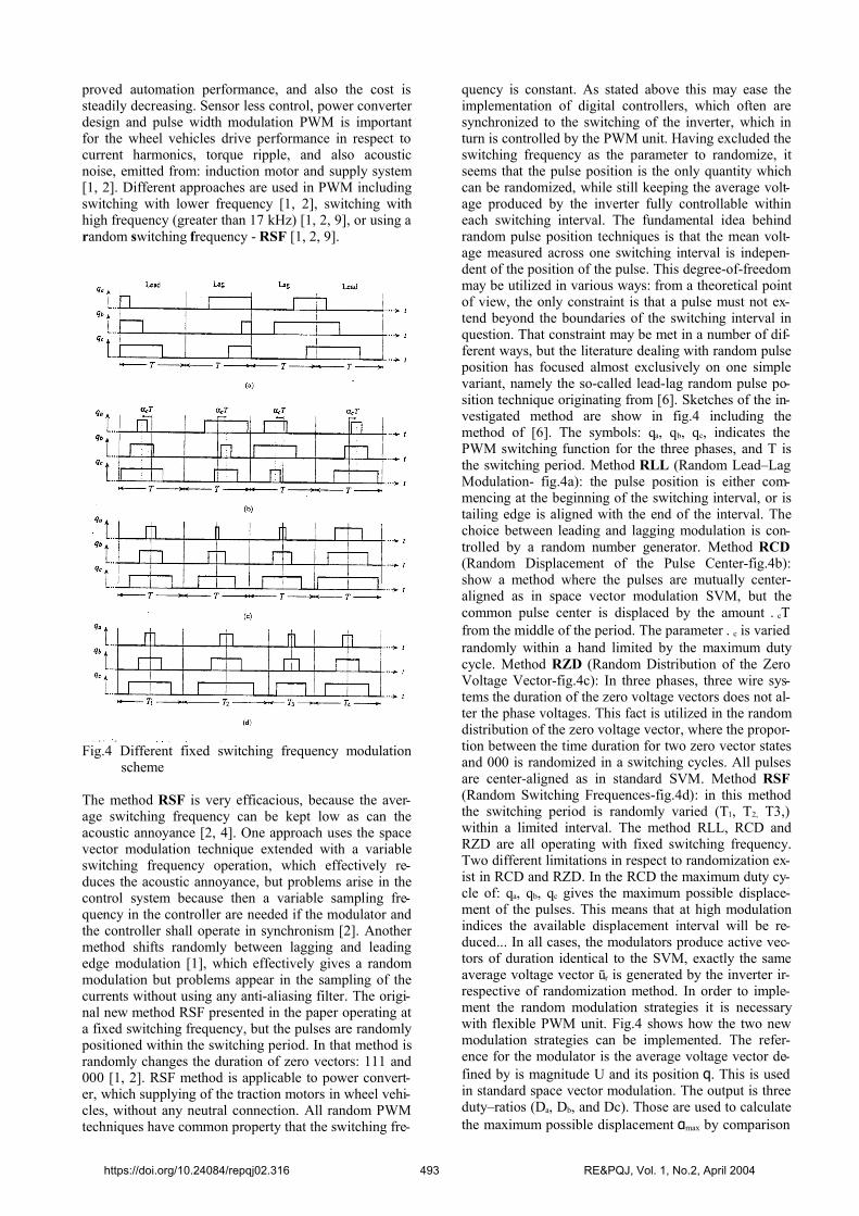
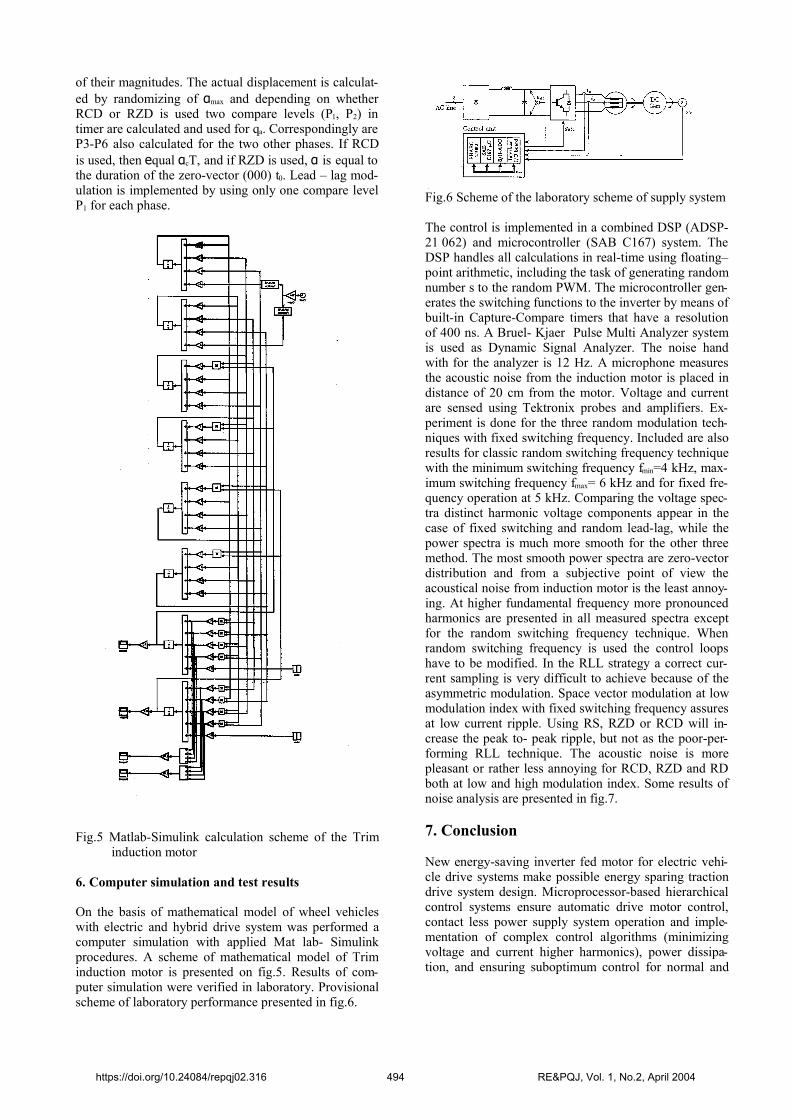
On the basis of mathematical model of wheel vehicleswith electric and hybrid drive system was performed acomputer simulation with applied Mat lab- Simulinkprocedures. A scheme of mathematical model of Triminduction motor is presented on fig.5. Results of com-puter simulation were verified in laboratory. Provisionalscheme of laboratory performance presented in fig.6.
Fig.6 Scheme of the laboratory scheme of supply system
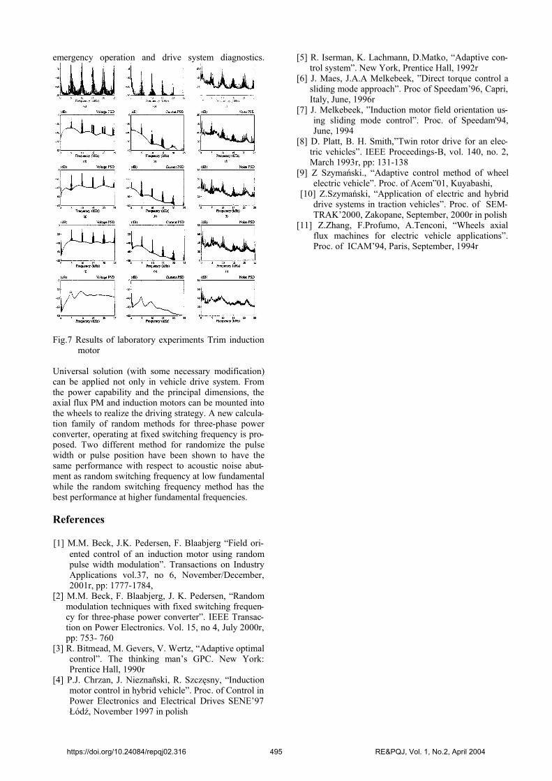
The control is implemented in a combined DSP (ADSP-21 062) and microcontroller (SAB C167) system. TheDSP handles all calculations in real-time using floating–point arithmetic, including the task of generating randomnumber s to the random PWM. The microcontroller gen-erates the switching functions to the inverter by means ofbuilt-in Capture-Compare timers that have a resolutionof 400 ns. A Bruel- Kjaer Pulse Multi Analyzer systemis used as Dynamic Signal Analyzer. The noise handwith for the analyzer is 12 Hz. A microphone measuresthe acoustic noise from the induction motor is placed indistance of 20 cm from the motor. Voltage and currentare sensed using Tektronix probes and amplifiers. Ex-periment is done for the three random modulation tech-niques with fixed switching frequency. Included are alsoresults for classic random switching frequency techniquewith the minimum switching frequency fmin=4 kHz, max-imum switching frequency fmax= 6 kHz and for fixed fre-quency operation at 5 kHz. Comparing the voltage spec-tra distinct harmonic voltage components appear in thecase of fixed switching and random lead-lag, while thepower spectra is much more smooth for the other threemethod. The most smooth power spectra are zero-vectordistribution and from a subjective point of view theacoustical noise from induction motor is the least annoy-ing. At higher fundamental frequency more pronouncedharmonics are presented in all measured spectra exceptfor the random switching frequency technique. Whenrandom switching frequency is used the control loopshave to be modified. In the RLL strategy a correct cur-rent sampling is very difficult to achieve because of theasymmetric modulation. Space vector modulation at lowmodulation index with fixed switching frequency assuresat low current ripple. Using RS, RZD or RCD will in-crease the peak to- peak ripple, but not as the poor-per-forming RLL technique. The acoustic noise is morepleasant or rather less annoying for RCD, RZD and RDboth at low and high modulation index. Some results ofnoise analysis are presented in fig.7.
7. Conclusion
New energy-saving inverter fed motor for electric vehi-cle drive systems make possible energy sparing tractiondrive system design. Microprocessor-based hierarchicalcontrol systems ensure automatic drive motor control,contact less power supply system operation and imple-mentation of complex control algorithms (minimizingvoltage and current higher harmonics), power dissipa-tion, and ensuring suboptimum control for normal and
https://doi.org/10.24084/repqj02.316 494 RE&PQJ, Vol. 1, No.2, April 2004
emergency operation and drive system diagnostics.
Fig.7 Results of laboratory experiments Trim inductionmotor
Universal solution (with some necessary modification)can be applied not only in vehicle drive system. Fromthe power capability and the principal dimensions, theaxial flux PM and induction motors can be mounted intothe wheels to realize the driving strategy. A new calcula-tion family of random methods for three-phase powerconverter, operating at fixed switching frequency is pro-posed. Two different method for randomize the pulsewidth or pulse position have been shown to have thesame performance with respect to acoustic noise abut-ment as random switching frequency at low fundamentalwhile the random switching frequency method has thebest performance at higher fundamental frequencies.
References
[1] M.M. Beck, J.K. Pedersen, F. Blaabjerg “Field ori-ented control of an induction motor using randompulse width modulation”. Transactions on IndustryApplications vol.37, no 6, November/December,2001r, pp: 1777-1784,
[2] M.M. Beck, F. Blaabjerg, J. K. Pedersen, “Randommodulation techniques with fixed switching frequen-cy for three-phase power converter”. IEEE Transac-tion on Power Electronics. Vol. 15, no 4, July 2000r,pp: 753- 760
[3] R. Bitmead, M. Gevers, V. Wertz, “Adaptive optimalcontrol”. The thinking man’s GPC. New York:Prentice Hall, 1990r
[4] P.J. Chrzan, J. Nieznañski, R. Szczęsny, “Inductionmotor control in hybrid vehicle”. Proc. of Control inPower Electronics and Electrical Drives SENE’97Łódź, November 1997 in polish
[5] R. Iserman, K. Lachmann, D.Matko, “Adaptive con-trol system”. New York, Prentice Hall, 1992r
[6] J. Maes, J.A.A Melkebeek, ”Direct torque control asliding mode approach”. Proc of Speedam’96, Capri,Italy, June, 1996r
[7] J. Melkebeek, ”Induction motor field orientation us-ing sliding mode control”. Proc. of Speedam'94,June, 1994
[8] D. Platt, B. H. Smith,”Twin rotor drive for an elec-tric vehicles”. IEEE Proceedings-B, vol. 140, no. 2,March 1993r, pp: 131-138
[9] Z Szymański., “Adaptive control method of wheelelectric vehicle”. Proc. of Acem”01, Kuyabashi,
[10] Z.Szymański, “Application of electric and hybriddrive systems in traction vehicles”. Proc. of SEM-TRAK’2000, Zakopane, September, 2000r in polish
[11] Z.Zhang, F.Profumo, A.Tenconi, “Wheels axialflux machines for electric vehicle applications”.Proc. of ICAM’94, Paris, September, 1994r
https://doi.org/10.24084/repqj02.316 495 RE&PQJ, Vol. 1, No.2, April 2004