Intelligent SCADA Systems - ICEweb and Lightning/Surge... · electrodes of IEC Class I spark gaps,...
15
Session Four: Comparison of Different Class I SPDs for the Protection of Mobile Phone Stations 2013 Earthing, Lightning & Surge Protection Conference – IDC Technologies 1 Session Four: Comparison of Different Class I Surge Protective De- vices for the Protection of Mobile Phone Stations Holger Heckler, John Ortika Phoenix Contact (Germany & Australia) Authors: Dipl.-Ing. Holger Heckler (Phoenix Contact GmbH & Co. KG, Germany) [email protected] John Ortika (Phoenix Contact Pty. Ltd., Australia) [email protected] Abstract IEC Class I surge protective devices (SPDs) - for the diversion of direct light- ning currents - are frequently used for the protection of low-voltage AC power systems. Nowadays more and more telecommunication applications are also powered with DC power systems. An example being radio base stations, which are equipped with Remote Radio Heads or Remote Radio Units (RRH/RRU). Remote radio heads are usually powered with 48 V DC. For the efficient protec- tion against the effects of direct lightning strikes, remote radio heads have to be protected with surge protective devices which are suitable for the installation in DC power systems. The IEC standards which describe the requirements and the test conditions for surge protective devices (IEC 61643-1, IEC 61643-11) do not address SPDs connected to DC power systems. In this paper special requirements for SPDs, connected to 48 V DC power systems, are defined and described. Tests carried out with different high performance Class I lightning current arresters, connect- ed to a newly designed test circuit, show the advantages and restrictions of the use of these arresters in DC power systems. The tests had been carried out with different kind of spark gaps, varistors and combinations of spark gaps and varistors. Introduction Lightning current arresters for low-voltage power systems are usually designed and tested only for use in AC power systems. The performance and operational behavior of a surge protective device, connected to an AC power system, can be completely different to the performance and operational behavior of the same surge protective device connected to a DC power system. The requirements and tests for surge protective devices (SPDs), connected to low voltage power systems, are described in the international standards IEC 61643-1 [1] and EN 61643-11 [2]. The scope of the IEC 61643-1 includes SPDs for AC applications with a rated voltage of up to 1000 V AC and SPDs for DC applications with a rated voltage of up to 1500 V DC. Unfortunately no test
Transcript of Intelligent SCADA Systems - ICEweb and Lightning/Surge... · electrodes of IEC Class I spark gaps,...
Session Four: Comparison of Different Class I SPDs for the Protection of Mobile Phone Stations
2013 Earthing, Lightning & Surge Protection Conference – IDC Technologies 1
Session Four:
Comparison of Different Class I Surge Protective De-vices for the Protection of Mobile Phone Stations
Holger Heckler, John Ortika Phoenix Contact (Germany & Australia)
Authors:
Dipl.-Ing. Holger Heckler (Phoenix Contact GmbH & Co. KG, Germany) [email protected]
John Ortika (Phoenix Contact Pty. Ltd., Australia) [email protected]
Abstract
IEC Class I surge protective devices (SPDs) - for the diversion of direct light-ning currents - are frequently used for the protection of low-voltage AC power systems. Nowadays more and more telecommunication applications are also powered with DC power systems. An example being radio base stations, which are equipped with Remote Radio Heads or Remote Radio Units (RRH/RRU). Remote radio heads are usually powered with 48 V DC. For the efficient protec-tion against the effects of direct lightning strikes, remote radio heads have to be protected with surge protective devices which are suitable for the installation in DC power systems.
The IEC standards which describe the requirements and the test conditions for surge protective devices (IEC 61643-1, IEC 61643-11) do not address SPDs connected to DC power systems. In this paper special requirements for SPDs, connected to 48 V DC power systems, are defined and described. Tests carried out with different high performance Class I lightning current arresters, connect-ed to a newly designed test circuit, show the advantages and restrictions of the use of these arresters in DC power systems. The tests had been carried out with different kind of spark gaps, varistors and combinations of spark gaps and varistors.
Introduction
Lightning current arresters for low-voltage power systems are usually designed and tested only for use in AC power systems. The performance and operational behavior of a surge protective device, connected to an AC power system, can be completely different to the performance and operational behavior of the same surge protective device connected to a DC power system.
The requirements and tests for surge protective devices (SPDs), connected to low voltage power systems, are described in the international standards IEC 61643-1 [1] and EN 61643-11 [2]. The scope of the IEC 61643-1 includes SPDs for AC applications with a rated voltage of up to 1000 V AC and SPDs for DC applications with a rated voltage of up to 1500 V DC. Unfortunately no test
Session Four: Comparison of Different Class I SPDs for the Protection of Mobile Phone Stations
2013 Earthing, Lightning & Surge Protection Conference – IDC Technologies 2
procedures for the testing of SPDs connected to DC power systems are includ-ed in this IEC standard. There is mention in the standard that the "testing of DC arresters" is under consideration.
Nowadays DC power systems are frequently used in industries such as photo-voltaic’s, telecommunications and the railway industry. Of these industries the photovoltaic industry currently has enormous growth. Photovoltaic systems, normally positioned in Lightning Protection Zone 0 (LPZ 0) areas, are highly susceptible to overvoltage’s and lightning damage. Many investigations have been performed in the past to examine the behavior of SPDs connected to pho-tovoltaic systems. The operational behavior of DC power systems can differ significantly from one specific application to another application. Since there are currently no test requirements for SPDs connected to DC power systems in the respective product standards, manufacturers of surge protection devices have to prove that the performance of an SPD, connected to a specific DC power system, is suitable for that specific application and the SPD in question can perform safely and effectively.
Considered Applications - Telecommunications
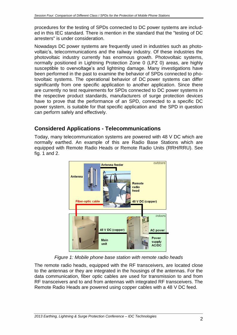
Today, many telecommunication systems are powered with 48 V DC which are normally earthed. An example of this are Radio Base Stations which are equipped with Remote Radio Heads or Remote Radio Units (RRH/RRU). See fig. 1 and 2.
Figure 1: Mobile phone base station with remote radio heads
The remote radio heads, equipped with the RF transceivers, are located close to the antennas or they are integrated in the housings of the antennas. For the data communication, fiber optic cables are used for transmission to and from RF transceivers and to and from antennas with integrated RF transceivers. The Remote Radio Heads are powered using copper cables with a 48 V DC feed.
Session Four: Comparison of Different Class I SPDs for the Protection of Mobile Phone Stations
2013 Earthing, Lightning & Surge Protection Conference – IDC Technologies 3
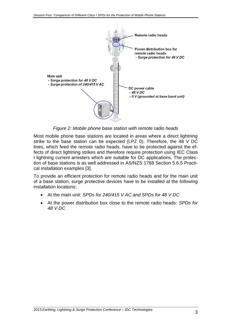
Figure 2: Mobile phone base station with remote radio heads
Most mobile phone base stations are located in areas where a direct lightning strike to the base station can be expected (LPZ 0). Therefore, the 48 V DC lines, which feed the remote radio heads, have to be protected against the ef-fects of direct lightning strikes and therefore require protection using IEC Class I lightning current arresters which are suitable for DC applications. The protec-tion of base stations is as well addressed in AS/NZS 1768 Section 5.6.5 Practi-cal installation examples [3].
To provide an efficient protection for remote radio heads and for the main unit of a base station, surge protective devices have to be installed at the following installation locations:
At the main unit: SPDs for 240/415 V AC and SPDs for 48 V DC
At the power distribution box close to the remote radio heads: SPDs for 48 V DC
Session Four: Comparison of Different Class I SPDs for the Protection of Mobile Phone Stations
2013 Earthing, Lightning & Surge Protection Conference – IDC Technologies 4
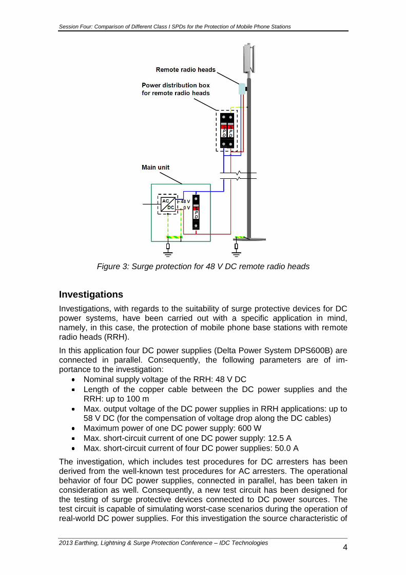
Figure 3: Surge protection for 48 V DC remote radio heads
Investigations
Investigations, with regards to the suitability of surge protective devices for DC power systems, have been carried out with a specific application in mind, namely, in this case, the protection of mobile phone base stations with remote radio heads (RRH).
In this application four DC power supplies (Delta Power System DPS600B) are connected in parallel. Consequently, the following parameters are of im-portance to the investigation:
Nominal supply voltage of the RRH: 48 V DC
Length of the copper cable between the DC power supplies and the RRH: up to 100 m
Max. output voltage of the DC power supplies in RRH applications: up to 58 V DC (for the compensation of voltage drop along the DC cables)
Maximum power of one DC power supply: 600 W
Max. short-circuit current of one DC power supply: 12.5 A
Max. short-circuit current of four DC power supplies: 50.0 A
The investigation, which includes test procedures for DC arresters has been derived from the well-known test procedures for AC arresters. The operational behavior of four DC power supplies, connected in parallel, has been taken in consideration as well. Consequently, a new test circuit has been designed for the testing of surge protective devices connected to DC power sources. The test circuit is capable of simulating worst-case scenarios during the operation of real-world DC power supplies. For this investigation the source characteristic of

Session Four: Comparison of Different Class I SPDs for the Protection of Mobile Phone Stations
2013 Earthing, Lightning & Surge Protection Conference – IDC Technologies 5
four DPS600B power supplies has been simulated using an arrangement of batteries. The source characteristic of the batteries is determined by measuring the off-loop voltage and on-load voltages connected to different loads for which the operational behavior of the batteries can be considered to be linear or near-ly linear (see fig. 4)
Figure 4: Source characteristic of the battery pack with an off-loop voltage of 64 V DC
To make sure that the worst-case behavior of four DPS600B power supplies can be simulated sufficiently using a battery pack, the source characteristic of the battery pack has to be compared with the source characteristic of four DPS600B power supplies connected in parallel (see fig. 5). The nominal supply voltage for remote radio heads is 48 V DC. To compensate for voltage drop on long DC supply lines, the output voltage of the DPS600B power supplies may be adjusted. For this application it is assumed that the output voltage of the power supplies may be adjusted to up to 58 V DC – in the case of long DC supply lines.
Figure 5: Source characteristics of DPS600B power supplies in comparison with the source characteristic of the battery pack
The source characteristic of the battery pack is always rated above the source characteristic of four DPS600B power supplies. Therefore it can be assumed that the battery pack can be used to adequately simulate the operational be-havior of four DPS600B power supplies under worst-case conditions. For the
Session Four: Comparison of Different Class I SPDs for the Protection of Mobile Phone Stations
2013 Earthing, Lightning & Surge Protection Conference – IDC Technologies 6
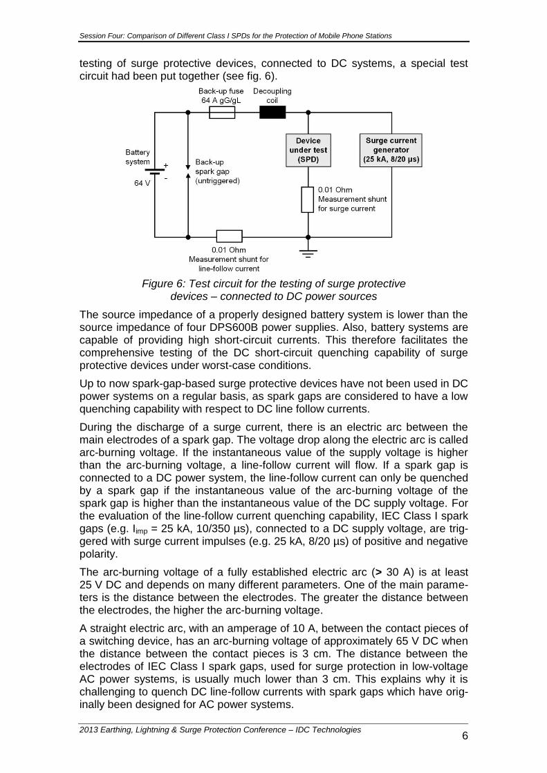
testing of surge protective devices, connected to DC systems, a special test circuit had been put together (see fig. 6).
Figure 6: Test circuit for the testing of surge protective devices – connected to DC power sources
The source impedance of a properly designed battery system is lower than the source impedance of four DPS600B power supplies. Also, battery systems are capable of providing high short-circuit currents. This therefore facilitates the comprehensive testing of the DC short-circuit quenching capability of surge protective devices under worst-case conditions.
Up to now spark-gap-based surge protective devices have not been used in DC power systems on a regular basis, as spark gaps are considered to have a low quenching capability with respect to DC line follow currents.
During the discharge of a surge current, there is an electric arc between the main electrodes of a spark gap. The voltage drop along the electric arc is called arc-burning voltage. If the instantaneous value of the supply voltage is higher than the arc-burning voltage, a line-follow current will flow. If a spark gap is connected to a DC power system, the line-follow current can only be quenched by a spark gap if the instantaneous value of the arc-burning voltage of the spark gap is higher than the instantaneous value of the DC supply voltage. For the evaluation of the line-follow current quenching capability, IEC Class I spark gaps (e.g. Iimp = 25 kA, 10/350 µs), connected to a DC supply voltage, are trig-gered with surge current impulses (e.g. 25 kA, 8/20 µs) of positive and negative polarity.
The arc-burning voltage of a fully established electric arc (> 30 A) is at least 25 V DC and depends on many different parameters. One of the main parame-ters is the distance between the electrodes. The greater the distance between the electrodes, the higher the arc-burning voltage.
A straight electric arc, with an amperage of 10 A, between the contact pieces of a switching device, has an arc-burning voltage of approximately 65 V DC when the distance between the contact pieces is 3 cm. The distance between the electrodes of IEC Class I spark gaps, used for surge protection in low-voltage AC power systems, is usually much lower than 3 cm. This explains why it is challenging to quench DC line-follow currents with spark gaps which have orig-inally been designed for AC power systems.
Session Four: Comparison of Different Class I SPDs for the Protection of Mobile Phone Stations
2013 Earthing, Lightning & Surge Protection Conference – IDC Technologies 7
To extinguish an electric arc, the arc-burning voltage of a spark gap has to be increased to the point at which it is higher than the voltage which drives the electric arc. The following physical principles can be used to increase the arc-burning voltage:
Lengthening of the electric arc
Splitting of one electric arc into several sub-arcs
Electric arc cooling
Quenching gas
Increase in pressure in the gap between the electrodes
Currently, in the design of surge protective devices, using spark gap technolo-gy, one or more of the above mentioned physical principles are used to in-crease the arc-burning voltage.
The focus of the investigation has been the evaluation of the line-follow current quenching capability in different types of Class I SPD. The lightning current dis-charge capacity of spark gaps is usually higher than the lightning current dis-charge capacity of varistors. Therefore spark-gap-based SPDs are mainly used for high-risk applications where high-energy long-duration lightning currents can be expected. Varistor-based SPDs are mainly used for medium-risk appli-cations. The following surge protective devices had been tested:
Untriggered Class I arc-chopping spark gap without quenching plates (FLT 60-400)
Triggered Class I arc-chopping spark gap with quenching plates (FLT-PLUS CTRL-0.9)
Triggered and encapsulated Class I spark gap (FLT-CP-350-ST)
Triggered and encapsulated Class I spark gap (FLT-CP-350-ST) con-nected in parallel with a Class II varistor (VAL-CP-350-ST)
Class I varistor (VAL-CP-T1/T2 48) Untriggered Class I arc-choping spark gap
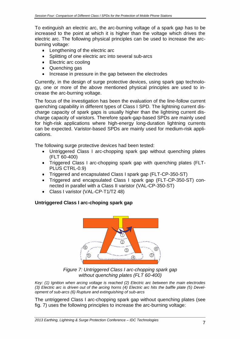
Figure 7: Untriggered Class I arc-chopping spark gap without quenching plates (FLT 60-400)
Key: (1) Ignition when arcing voltage is reached (2) Electric arc between the main electrodes (3) Electric arc is driven out of the arcing horns (4) Electric arc hits the baffle plate (5) Devel-opment of sub-arcs (6) Rupture and extinguishing of sub-arcs
The untriggered Class I arc-chopping spark gap without quenching plates (see fig. 7) uses the following principles to increase the arc-burning voltage:
Session Four: Comparison of Different Class I SPDs for the Protection of Mobile Phone Stations
2013 Earthing, Lightning & Surge Protection Conference – IDC Technologies 8
Lengthening of the electric arc
Splitting of one electric arc into several sub-arcs
Quenching gas
Test results for the FLT 60-400 connected to a 64 V DC battery system:
After triggering with a 25 kA (8/20 µs) surge current impulse, a DC line follow current of 550 A flowed until the back-up fuse blew.
The FLT 60-400 was not able to quench the DC line-follow current.
The FLT 60-400 is not suitable for the protection of remote radio heads (48 V DC)
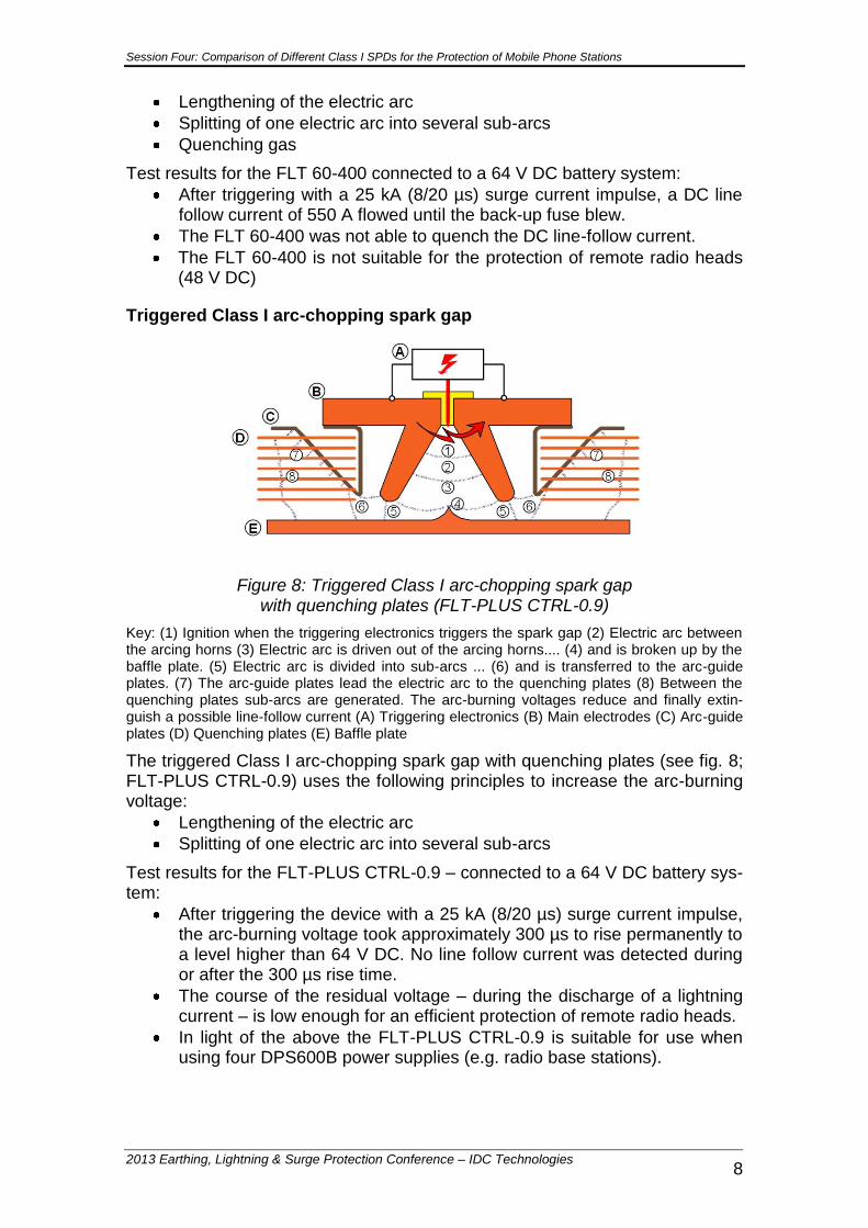
Triggered Class I arc-chopping spark gap
Figure 8: Triggered Class I arc-chopping spark gap with quenching plates (FLT-PLUS CTRL-0.9)
Key: (1) Ignition when the triggering electronics triggers the spark gap (2) Electric arc between the arcing horns (3) Electric arc is driven out of the arcing horns.... (4) and is broken up by the baffle plate. (5) Electric arc is divided into sub-arcs ... (6) and is transferred to the arc-guide plates. (7) The arc-guide plates lead the electric arc to the quenching plates (8) Between the quenching plates sub-arcs are generated. The arc-burning voltages reduce and finally extin-guish a possible line-follow current (A) Triggering electronics (B) Main electrodes (C) Arc-guide plates (D) Quenching plates (E) Baffle plate
The triggered Class I arc-chopping spark gap with quenching plates (see fig. 8; FLT-PLUS CTRL-0.9) uses the following principles to increase the arc-burning voltage:
Lengthening of the electric arc
Splitting of one electric arc into several sub-arcs
Test results for the FLT-PLUS CTRL-0.9 – connected to a 64 V DC battery sys-tem:
After triggering the device with a 25 kA (8/20 µs) surge current impulse, the arc-burning voltage took approximately 300 µs to rise permanently to a level higher than 64 V DC. No line follow current was detected during or after the 300 µs rise time.
The course of the residual voltage – during the discharge of a lightning current – is low enough for an efficient protection of remote radio heads.
In light of the above the FLT-PLUS CTRL-0.9 is suitable for use when using four DPS600B power supplies (e.g. radio base stations).
Session Four: Comparison of Different Class I SPDs for the Protection of Mobile Phone Stations
2013 Earthing, Lightning & Surge Protection Conference – IDC Technologies 9
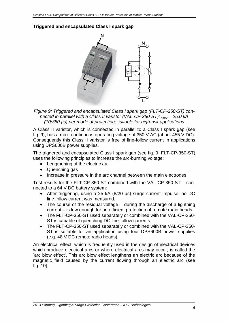
Triggered and encapsulated Class I spark gap
Figure 9: Triggered and encapsulated Class I spark gap (FLT-CP-350-ST) con-nected in parallel with a Class II varistor (VAL-CP-350-ST); Iimp = 25.0 kA
(10/350 µs) per mode of protection; suitable for high-risk applications
A Class II varistor, which is connected in parallel to a Class I spark gap (see fig. 9), has a max. continuous operating voltage of 350 V AC (about 455 V DC). Consequently this Class II varistor is free of line-follow current in applications using DPS600B power supplies.
The triggered and encapsulated Class I spark gap (see fig. 9; FLT-CP-350-ST) uses the following principles to increase the arc-burning voltage:
Lengthening of the electric arc
Quenching gas
Increase in pressure in the arc channel between the main electrodes
Test results for the FLT-CP-350-ST combined with the VAL-CP-350-ST – con-nected to a 64 V DC battery system:
After triggering, using a 25 kA (8/20 µs) surge current impulse, no DC line follow current was measured.
The course of the residual voltage – during the discharge of a lightning current – is low enough for an efficient protection of remote radio heads.
The FLT-CP-350-ST used separately or combined with the VAL-CP-350-ST is capable of quenching DC line-follow currents.
The FLT-CP-350-ST used separately or combined with the VAL-CP-350-ST is suitable for an application using four DPS600B power supplies (e.g. 48 V DC remote radio heads).
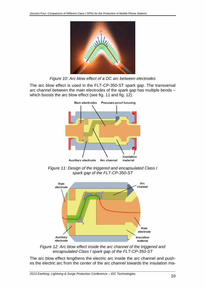
An electrical effect, which is frequently used in the design of electrical devices which produce electrical arcs or where electrical arcs may occur, is called the ‘arc blow effect’. This arc blow effect lengthens an electric arc because of the magnetic field caused by the current flowing through an electric arc (see fig. 10).
Session Four: Comparison of Different Class I SPDs for the Protection of Mobile Phone Stations
2013 Earthing, Lightning & Surge Protection Conference – IDC Technologies 10
Figure 10: Arc blow effect of a DC arc between electrodes
The arc blow effect is used in the FLT-CP-350-ST spark gap. The transversal arc channel between the main electrodes of the spark gap has multiple bends – which boosts the arc blow effect (see fig. 11 and fig. 12).
Figure 11: Design of the triggered and encapsulated Class I spark gap of the FLT-CP-350-ST
Figure 12: Arc blow effect inside the arc channel of the triggered and encapsulated Class I spark gap of the FLT-CP-350-ST
The arc blow effect lengthens the electric arc inside the arc channel and push-es the electric arc from the center of the arc channel towards the insulation ma-
Session Four: Comparison of Different Class I SPDs for the Protection of Mobile Phone Stations
2013 Earthing, Lightning & Surge Protection Conference – IDC Technologies 11
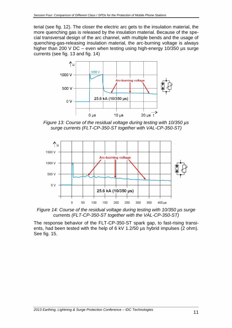
terial (see fig. 12). The closer the electric arc gets to the insulation material, the more quenching gas is released by the insulation material. Because of the spe-cial transversal design of the arc channel, with multiple bends and the usage of quenching-gas-releasing insulation material, the arc-burning voltage is always higher than 200 V DC – even when testing using high-energy 10/350 µs surge currents (see fig. 13 and fig. 14)
Figure 13: Course of the residual voltage during testing with 10/350 µs surge currents (FLT-CP-350-ST together with VAL-CP-350-ST)
Figure 14: Course of the residual voltage during testing with 10/350 µs surge currents (FLT-CP-350-ST together with the VAL-CP-350-ST)
The response behavior of the FLT-CP-350-ST spark gap, to fast-rising transi-ents, had been tested with the help of 6 kV 1.2/50 µs hybrid impulses (2 ohm). See fig. 15.
Session Four: Comparison of Different Class I SPDs for the Protection of Mobile Phone Stations
2013 Earthing, Lightning & Surge Protection Conference – IDC Technologies 12
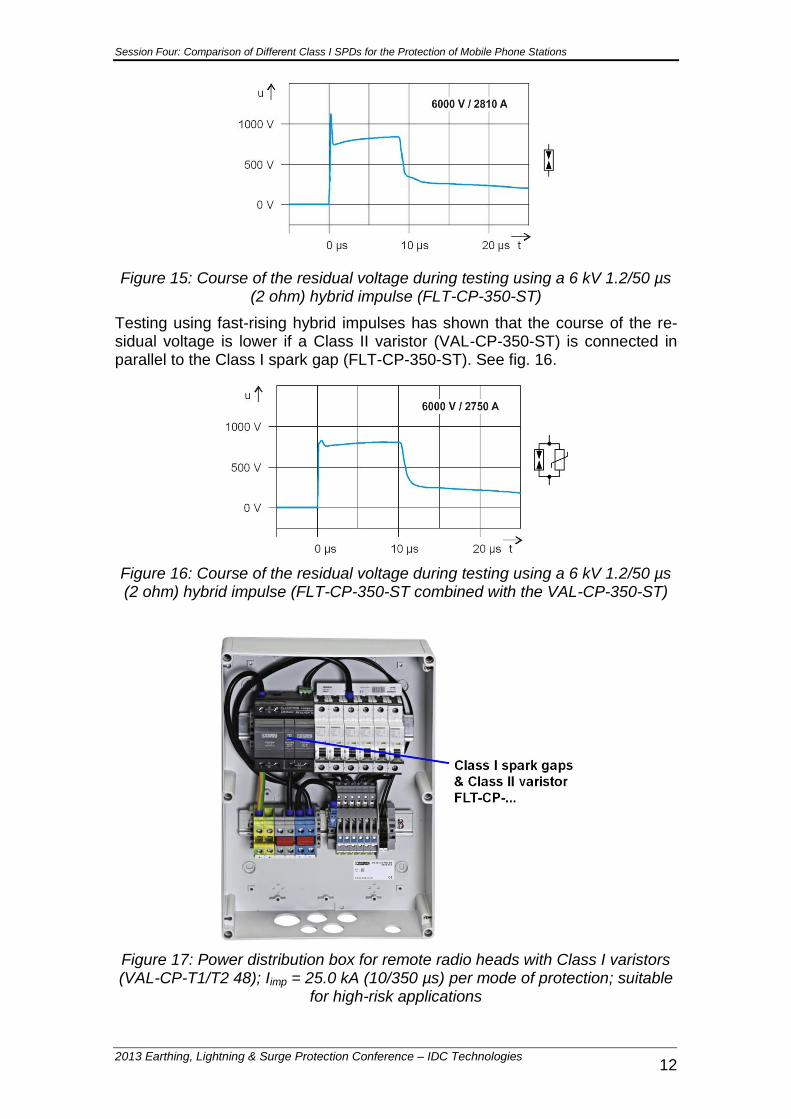
Figure 15: Course of the residual voltage during testing using a 6 kV 1.2/50 µs (2 ohm) hybrid impulse (FLT-CP-350-ST)
Testing using fast-rising hybrid impulses has shown that the course of the re-sidual voltage is lower if a Class II varistor (VAL-CP-350-ST) is connected in parallel to the Class I spark gap (FLT-CP-350-ST). See fig. 16.
Figure 16: Course of the residual voltage during testing using a 6 kV 1.2/50 µs (2 ohm) hybrid impulse (FLT-CP-350-ST combined with the VAL-CP-350-ST)
Figure 17: Power distribution box for remote radio heads with Class I varistors (VAL-CP-T1/T2 48); Iimp = 25.0 kA (10/350 µs) per mode of protection; suitable
for high-risk applications

Session Four: Comparison of Different Class I SPDs for the Protection of Mobile Phone Stations
2013 Earthing, Lightning & Surge Protection Conference – IDC Technologies 13
Class I varistor
During the last couple of years more and more powerful Class I varistors have been introduced to the market. An example for this is the VAL-MS-T1/T2 48 which has been designed for the protection of remote radio heads with a nomi-nal voltage of 48 V DC.
Figure 18: Class I spark gap varistor (VAL-CP-T1/T2 48); Iimp = 12.5 kA (10/350 µs) per mode of protection; suitable for medium-risk applications
Figure 19: Course of the residual voltage during testing with 10/350 µs surge currents (VAL-CP-T1/T2 48)
Figure 20: Course of the residual voltage during testing with 8/20 µs surge currents (VAL-CP-T1/T2 48)
Session Four: Comparison of Different Class I SPDs for the Protection of Mobile Phone Stations
2013 Earthing, Lightning & Surge Protection Conference – IDC Technologies 14
Test results for the VAL-MS-T1/T2 48 – connected to a 64 V DC battery sys-tem:
The max. continuous operating voltage of the VAL-MS-T1/T2 48 is high-er than the max. supply voltage of the power of the DPS600B power supplies. Therefore no line-follow current flowed during the tests.
The course of the residual voltage – during the discharge of a lightning current – is low enough for an efficient protection of remote radio heads (48 V DC).
The VAL-MS-T1/T2 48 is suitable for an application using four DPS600B power supplies.
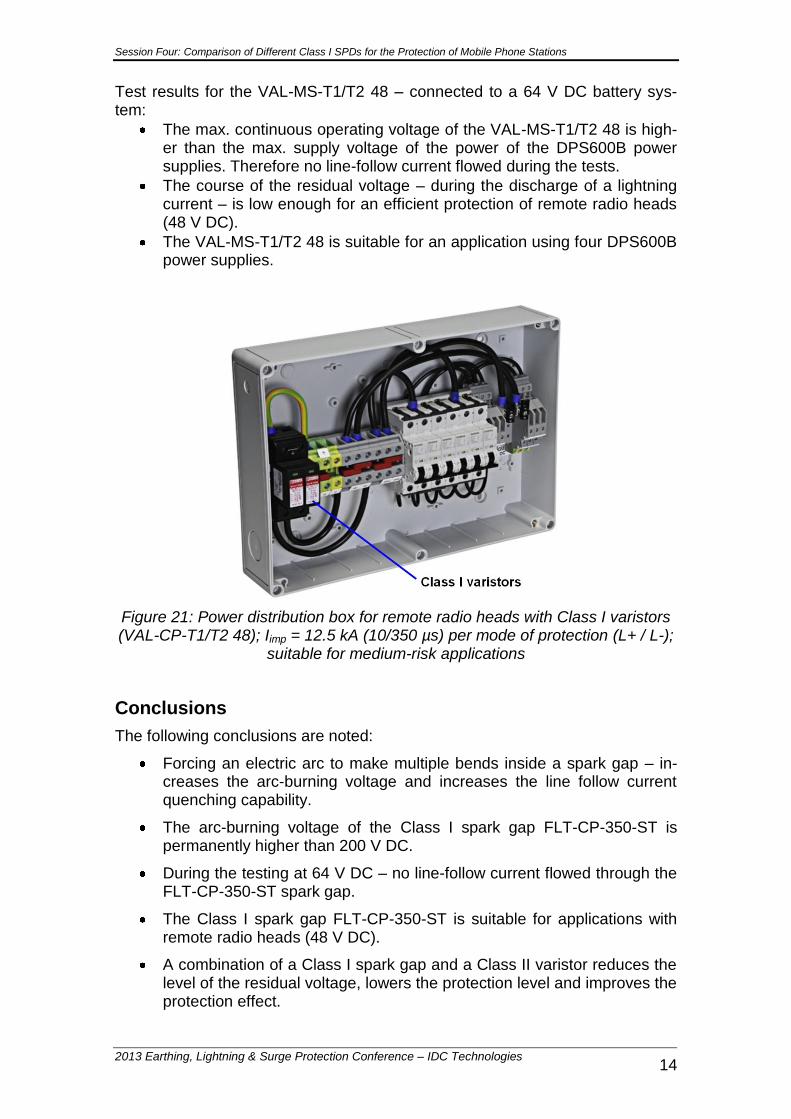
Figure 21: Power distribution box for remote radio heads with Class I varistors (VAL-CP-T1/T2 48); Iimp = 12.5 kA (10/350 µs) per mode of protection (L+ / L-);
suitable for medium-risk applications
Conclusions
The following conclusions are noted:
Forcing an electric arc to make multiple bends inside a spark gap – in-creases the arc-burning voltage and increases the line follow current quenching capability.
The arc-burning voltage of the Class I spark gap FLT-CP-350-ST is permanently higher than 200 V DC.
During the testing at 64 V DC – no line-follow current flowed through the FLT-CP-350-ST spark gap.
The Class I spark gap FLT-CP-350-ST is suitable for applications with remote radio heads (48 V DC).
A combination of a Class I spark gap and a Class II varistor reduces the level of the residual voltage, lowers the protection level and improves the protection effect.
Session Four: Comparison of Different Class I SPDs for the Protection of Mobile Phone Stations
2013 Earthing, Lightning & Surge Protection Conference – IDC Technologies 15
The Class I varistor VAL-MS-T1/T2 48 is suitable for applications with remote radio heads (48 V DC).
Field experience indicates that the following lightning current discharge capacities can be recommended for the protection of remote radio heads (48 V DC):
o High-risk applications: Iimp = 25 kA (10/350 µs) per mode of pro-tection (e.g. FLT-CP-350-ST)
o Medium-risk applications: Iimp = 12.5 kA (10/350 µs) per mode of protection (e.g. VAL-MS-T1/T2 48)
References
1. IEC 61643-1: Low-voltage surge protective devices – Part 1: Surge pro-tective devices connected to low-voltage power distribution systems – Requirements and tests (2005)
2. EN 61643-11: Low-voltage surge protective devices – Part 11: Surge protective devices connected to low-voltage power systems – Require-ments and tests (2007)
3. AS/NZS 1768: Lightning protection (2007) 4. Finis, G., Wosgien, J., Wetter, M.: Varistor-based Surge Protection for
Photovoltaic systems. 29th International Conference on Lightning Pro-tection, (ICLP), Uppsala – Sweden, 23.-26. June, Proceedings 7a-3, P. 153, (2008)
5. Finis, G., Heckler, H., Wosgien, J.: Blitz- und Überspannungsschutz-Konzept für PV-Anlagen, etz Elektrotechnik + Automation, S. 54-57, Ausgabe 1/2010