INTELLIGENT HOME AUTOMATION SYSTEM
99
INTELLIGENT HOME AUTOMATION SYSTEM MAK KWAN WUEY A project report submitted in partial fulfilment of the requirements for the award of the degree of Bachelor (Hons.) of Electronics and Communications Engineering Faculty of Engineering and Science Universiti Tunku Abdul Rahman May 2011
Transcript of INTELLIGENT HOME AUTOMATION SYSTEM

INTELLIGENT HOME AUTOMATION SYSTEM
MAK KWAN WUEY
A project report submitted in partial fulfilment of the
requirements for the award of the degree of
Bachelor (Hons.) of Electronics and Communications Engineering
Faculty of Engineering and Science
Universiti Tunku Abdul Rahman
May 2011

ii
DECLARATION
I hereby declare that this project report is based on my original work except for
citations and quotations which have been duly acknowledged. I also declare that it
has not been previously and concurrently submitted for any other degree or award at
UTAR or other institutions.
Signature : _________________________
Name : _________________________
ID No. : _________________________
Date : _________________________

iii
APPROVAL FOR SUBMISSION
I certify that this project report entitled “INTELLIGENT HOME AUTOMATION
SYSTEM was prepared by MAK KWAN WUEY has met the required standard for
submission in partial fulfilment of the requirements for the award of Bachelor (Hons.)
of Electronics and Communications Engineering at Universiti Tunku Abdul Rahman.
Approved by,
Signature : _________________________
Supervisor : Dr Goi Bok Min
Date : _________________________
iv
The copyright of this report belongs to the author under the terms of the
copyright Act 1987 as qualified by Intellectual Property Policy of University Tunku
Abdul Rahman. Due acknowledgement shall always be made of the use of any
material contained in, or derived from, this report.
© 2011, Mak Kwan Wuey. All right reserved.

v
Specially dedicated to
My beloved mother and father

vi
ACKNOWLEDGEMENTS
Throughout this project, I would like to thank Dr Goi Bok Min, my supervisor for
guiding me in this project for the difficulties I faced, and Liu Chee Wei, who has
given me valuable feedbacks in designing this system as a whole. My gratitude
extends to my families and my housemate that has supports me in this project.

vii
INTELLIGENT HOME AUTOMATION SYSTEM
ABSTRACT
Intelligent Home Automation System (IHAS) is a computer based wireless home
automation system that uses Adobe Flash for the user interface, enabling users to
control physical devices on their computer. IHAS uses 802.15.4 in controlling
various types of devices. IHAS is developed as a low cost alternative in home
automation technology as it doesn’t need a dedicated hardware console. The aim of
this project is to reduce the cost associate to home automation, which will encourage
more people to install home automation technology in their home. IHAS has
achieved success in implementing core features such as plug and play coordinator
setup, RFID control and integration, AES128 encrypted communication,
communication fault detect and control extension to an Android smartphone device.
Also, IHAS control interface is optimized for both mouse control and touch input.
This is possible with the use of Adobe Flash which is a web based multimedia
platform. One of the major challenges in this project is how to send data over COM
port using Adobe Flash, as it does not natively support such feature. Also, setting up
a secure connection between coordinator and end devices is another challenge that
has been solved in IHAS. In short, IHAS is successful and have achieved the aims
and objectives. Improvement has to be made to the overall stability of IHAS and
integration of IHAS and commercial products could be further investigated. Also,
IHAS could expand to control various types of devices, from power monitoring to
security in the future.

viii
TABLE OF CONTENTS
DECLARATION ii
APPROVAL FOR SUBMISSION iii
ACKNOWLEDGEMENTS vi
ABSTRACT vii
TABLE OF CONTENTS viii
LIST OF TABLES xii
LIST OF FIGURES xiii
LIST OF SYMBOLS / ABBREVIATIONS xvi
LIST OF APPENDICES xvii
CHAPTER
1 INTRODUCTION 18
1.1 Background 18
1.2 Justification and Motivation 19
1.3 Aims and Objectives 20
1.4 Methodology 20
1.5 Project Scopes 22
1.6 Thesis Outline 22
2 LITERATURE REVIEW 23
2.1 Communication protocol 23
2.1.1 Communications Protocol Background 23
2.1.2 Number of supported devices 24
2.1.3 Network Topology 24

ix
2.1.4 Power Requirement 25
2.1.5 Security 26
2.1.6 Hardware requirements 26
2.1.7 Other Considerations 27
2.1.8 Summary 27
2.2 XBEE 28
2.2.1 XBEE Hardware 28
2.2.2 XBEE Setup and Command Modes 29
2.3 RFID in Intelligent Home Automation System 33
2.4 User Interface Design 34
2.4.1 User Interface Design Guidelines 34
2.4.2 Comparison between Visual Basic and Adobe Flash
35
2.4.3 Adobe Flash with Serial Port Communication 36
2.5 Software 36
2.5.1 Adobe Flash Professional CS5 36
2.5.2 MDM Zinc 3.0.22 37
2.5.3 Eterlogic Virtual Serial Ports Emulator 0.938.4.846
38
2.5.4 AGGsoftware Com Port Data Emulator 2.7.1 build
622 38
2.5.5 XCTU 32-bit ver. 5.1.4.1 39
2.5.6 TightVNC version 2.0 39
3 INTELLIGENT HOME AUTOMATION SYSTEM 40
3.1 Overview 40
3.2 Management Console 41
3.3 User Interface for Main Menu 41
3.4 User Interface for Lights 42
3.5 Automated Plug and Play Coordinator Setup 42
3.6 Automated Scanning for End Devices Status 44
3.7 Remote Encryption Settings for End Devices 45
3.8 IHAS Communications Format and Protocol 46
x
3.9 RFID Integration in IHAS 47
3.10 Modular Design 48
3.11 Smartphone Controlled IHAS 49
3.12 Compatibility of IHAS with Commercial Products 50
4 IMPLEMENTATION OF IHAS AND OUTCOMES 53
4.1 Sending Data through a Com Port 53
4.1.1 Implementation 53
4.1.2 Outcome 57
4.2 Design a User Friendly UI 61
4.2.1 Implementation 61
4.2.2 Outcome 61
4.3 Automated Setup for XBEE Coordinator 64
4.3.1 Implementation 64
4.3.2 Outcome 65
4.4 Automated Scanning for End Devices Status 66
4.4.1 Implementation 66
4.4.2 Outcome 67
4.5 Remote Encryption Settings for End Devices 68
4.5.1 Implementation 68
4.5.2 Outcome 70
4.6 RFID Integration with IHAS 70
4.6.1 Implementation 70
4.6.2 Outcome 72
4.7 Smartphone Controlled IHAS 73
4.7.1 Implementation 73
4.7.2 Outcome 73
4.8 Design Solution based on commercial products 75
4.8.1 Implementation 75
4.8.2 Outcome 81
5 CONCLUSION AND FUTURE IMPLEMENTATION 83

xi
REFERENCES 84
xii
LIST OF TABLES
TABLE TITLE PAGE
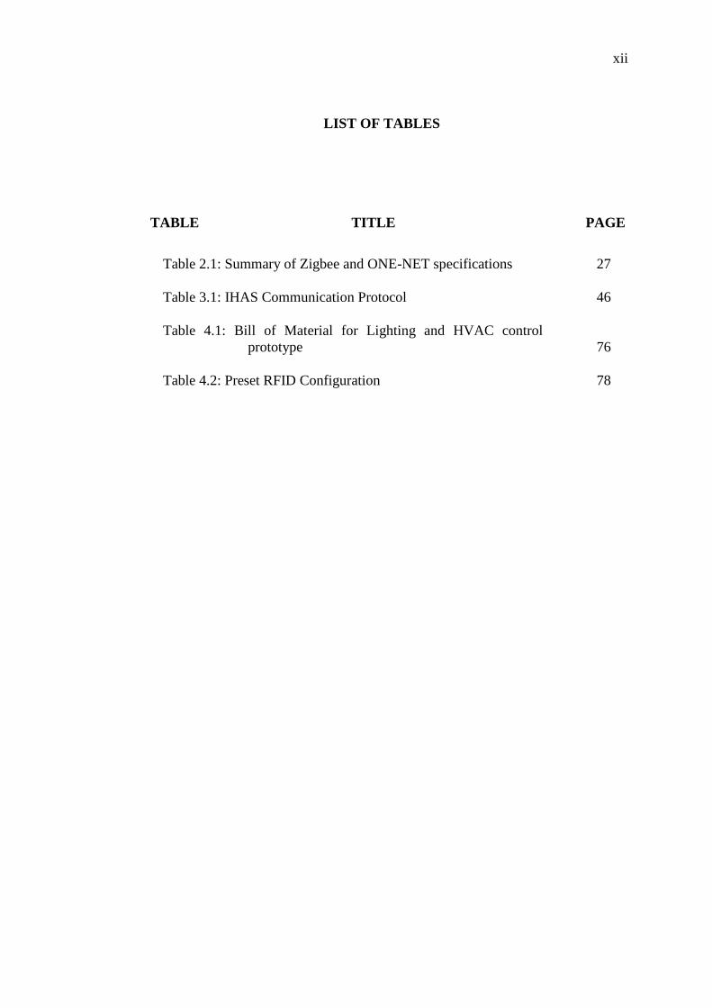
Table 2.1: Summary of Zigbee and ONE-NET specifications 27
Table 3.1: IHAS Communication Protocol 46
Table 4.1: Bill of Material for Lighting and HVAC control
prototype 76
Table 4.2: Preset RFID Configuration 78

xiii
LIST OF FIGURES
FIGURE TITLE PAGE
Figure 1.1: Intel Intelligent Home Management Proof of Concept
(Kanellos, 2010) 19
Figure 2.1: Zigbee Network Topologies 24
Figure 2.2: A Pair of XBEE Starter Kit 28
Figure 2.3: Entering AT Command Flow Chart 30
Figure 2.4: AT Command format 30
Figure 2.5: API for AT command 31
Figure 2.6: Example of API Mode Frame Data 32
Figure 2.7: RFID and RFID tags 33
Figure 2.8: Adobe Flash (Adobe Flash Professional CS5) 36
Figure 2.9: MDM Zinc 3.0.22 (Multidmedia Ltd, 2002) 37
Figure 2.10: Eterlogic Virtual Serial Ports Emulator 0.938.4.846
(ETERLOGIC, 2007) 38
Figure 2.11: AGGsoftware Com Port Data Emulator
(AGGsoftware, 1999) 38
Figure 2.12: XCTU 32-bit ver. 5.1.4.1 interface 39
Figure 2.13 : TightVNC Server Version 2.0 39
Figure 3.1: Overall Block Diagram for Intelligent Home
Automation System 40
Figure 3.2: Block Diagram for Management Console 41
Figure 3.3: Management Console Main Menu 41
Figure 3.4: Lighting Control Page 42

xiv
Figure 3.5: Automated Setup of Coordinator for XBEE 43
Figure 3.6: IHAS Communication Protocol Example 46
Figure 3.7: When IHAS Detects RFID 47
Figure 3.8: Registering new RFID card to IHAS database 48
Figure 3.9: RFID Hardware Modular Design 49
Figure 3.10: Design Solution for Energy Savings On Campus 51
Figure 3.11: Design Concept on management console 52
Figure 4.1: Zinc 3.0 54
Figure 4.2: Virtual Serial Com port 55
Figure 4.3: Com Port Emulator Setup 55
Figure 4.4: Configuring Data Emulator to Send Data 56
Figure 4.5: Scanning Ports 57
Figure 4.6: Started Com Port Emulator Before Starting Up
Application 58
Figure 4.7: Result from Application Testing (Send) 59
Figure 4.8: Result from Application Testing (Receive) 60
Figure 4.9: Main Menu 61
Figure 4.10: Lights Control Page (full) 62
Figure 4.11: Lights Control (desktop mode) 63
Figure 4.12: Flow chart to configure XBEE settings automatically 64
Figure 4.13: Plug and Play XBEE Coordinator Easy Setup 65
Figure 4.14: Steps to Detect and Save End Devices to Database 66
Figure 4.15: End Device Scanning 67
Figure 4.16: endnodes.xml Datafile 67
Figure 4.17: Remote Encryption Setting 68
Figure 4.18: API Frame Example 69

xv
Figure 4.19: Security Setup 70
Figure 4.20: Modular design of RFID Conversion Circuit 71
Figure 4.21: RFID Conversion Circuit and Power Conversion and
Regulation Circuit 72
Figure 4.22: Complete RFID Hardware 72
Figure 4.23: Smartphone (left) and IHAS Application(right) 73
Figure 4.24: Smartphone Streaming IHAS Application 74
Figure 4.25: Electrical Wiring diagram for HVAC and Lighting
Control System Prototype 75
Figure 4.26(A): Lighting Control Prototype 77
Figure 4.27: Different Preset Modes, from left clockwise ( OHP
mode, Projector mode and All On ) 79
Figure 4.28: HVAC Prototype 80
Figure 4.29: The Lighting and HVAC Control System Prototype 81
Figure 4.30: IEEE STUDENT Conference 2010 Best Exhibitor
Award Winner, From left, MAK KWAN WUEY,
LIU CHEE WEI, GAN YU HAN. 82

xvi
LIST OF SYMBOLS / ABBREVIATIONS
RFID Radio Frequency Identification
IHAS Intelligent Home Automation System
MICS Modular Intelligent Control System
DALI Digital Addressable Lighting Interface
UI User Interface
WSA Wide Sensor Array
AES Advance Encryption Standard
XTEA-2 eXtended Tiny Encryption Algorithm version 2
ROM Read-Only Memory
RAM Random Access Memory
GUI Graphical User Interface
EXE Executable File
PC Personal Computer
USB Universal Serial Bus
XML Extensible Markup Language
FLA Flash Movie Authoring File
RS-232 Recommended Standard 232
TCP/IP Transmission Control Protocol/Internet Protocol
UDP User Datagram Protocol
AT A prefix to enter the command mode of XBEE
API Application Programming Interface (XBEE)
PLC Programmable Logic Controller
AHU Air Handling Unit
HVAC Heating, Ventilation and Air Conditioning

xvii
LIST OF APPENDICES
APPENDIX TITLE PAGE
Appendix A XBEE Command List 84
Appendix B Baseline Data and Energy Savings Calculation 91

18
CHAPTER 1
1 INTRODUCTION
1.1 Background
Home automation system existed for decades but due to its high cost, it remains as a
niche product for the high end consumers. With energy crisis looming in the horizon,
home automation devices’ popularity has seen an uptake to reduce unnecessary
electricity consumption. However, mass adoption of home automation technology is
not possible unless there is a significant cost reduction in installation of home
automation system. Therefore, we have to identify and implement ways to reduce the
installation cost of home automation systems. Wireless system appeals to us as we
could cut down wiring cost in conventional home automation system.
Home automation system could not be complete without a control and
monitoring console. Figure 1.1 shows an example energy management console from
Intel, which integrates answering machines and household clocks on the home
energy management console (Kanellos, 2010). Intel tries to make energy
management a part of our daily lives, by requiring us to interact with it daily. Instead
of a dedicated console, we believe we could do the same thing on the computer as we
interact with the computer most of the time, not to mention we could save the cost of
installing a dedicated energy management console.

19
Figure 1.1: Intel Intelligent Home Management Proof of Concept (Kanellos, 2010)
In this project, IHAS will offer lighting control as a proof of concept. Also,
IHAS also provides multiple methods in lighting control such as central console from
computer, RFID control and control via smartphone.
1.2 Justification and Motivation
The reason that motivates us to develop such system is that there is a need for cheap
and easy to implement home automation system. By using an open protocol, we
could save license fee for proprietary and close protocol. By choosing a wireless
communication medium, we could save wiring and installation cost as we could
reuse existing infrastructure with minimal modification. By developing an
application that enables users to control devices from the computer instead of a
dedicated console, we could save the cost for the need of a dedicated automation
console.

20
1.3 Aims and Objectives
The aim of this project is to build a cost effective wireless home automation system
that is based on an open protocol, easy to configure and setup home automation
system, RFID control and secured communication. It is hoped that our project will
spark the interest of home automation manufacturer in low cost home automation
technology that is affordable to mass market.
Therefore, the objectives in this project are:
Build a robust and scalable wireless home automation system that is suitable
for multiple devices such as lights.
Implement wireless security to avoid potential malicious attacks to the home
automation system.
Design a home automation management console that is controlled from a
personal computer, which is both intuitive and appealing to all kinds of home
users.
Evaluate and implement various intelligent features that could make IHAS
stand out among competing solutions such as automation control from
smartphones, RFID lighting control and plug and play easy setup.
1.4 Methodology
The project starts from a comprehensive study on the communications protocol,
effective User Interface (UI) design and implementation of various planned features
for IHAS. We have to research on the alternatives, evaluate the performance of each
and choose the best solution for our project. The sources of information could be
obtained but not limited to website, journals, books, electronics news source and
company’s newsletter.

21
After choosing the technology and related method, we have to test out
systematically towards the aims and objectives of the proposed system. For example,
we have examined how to send a simple data through Zigbee after we have chosen
Zigbee as our communication protocol. Also, we have to examine if the chosen
software to create the home automation console is capable of transmitting and
receiving data from a Zigbee transceiver. All tests conducted are detailed in this
report.
When communications is proved to be working, planned features such as
easy plug and play setup, RFID lighting control, wireless security and automation
control from smartphone are implemented and tested individually.
Finally, when individual features are working, all features are put together as
a complete system. IHAS is tested with a lighting control system in collaboration of
Smart Lighting System: Modular Intelligent Control System (Wei, 2010).

22
1.5 Project Scopes
This project comprises mainly 2 sections, the Intelligent Home Automation System
(IHAS) and Smart Lighting System: Modular Intelligent Control System (Wei, 2010).
IHAS presents the devices and control panel in a logical and attractive manner to the
users. Also, IHAS also handles setup of communication network between the users
and Smart Lighting System: Modular Intelligent Control System. IHAS also provides
an alternative way to control groups of lights, which is through personalized lighting
profiles. Smart Lighting System: Modular Intelligent Control System on the other
hand, deals with physical devices which can be controlled by IHAS.
1.6 Thesis Outline
This thesis will start off with a discussion of home automation communication
protocols that are available in the market and the hardware that are needed for IHAS.
Also, effective user interface design concept is also studied and analysed, which is
needed in designing IHAS application.
In the succeeding chapter, IHAS features and concept will be discussed in
detail, while exploring the possibilities of using IHAS with commercial products.
The next chapter that come after will discuss how to achieve and implement
some of the features that are mentioned in the preceding chapter. Outcome of the
implementations are also presented in the same chapter.
Finally, a brief conclusion on the current work on IHAS and the future
implementation and direction of IHAS will be available at the last chapter.

23
CHAPTER 2
2 LITERATURE REVIEW
2.1 Communication protocol
Currently, there are quite a number of communication protocols for home automation
system such as INSTEON, BACnet, X10, KNX, LonWorks, C-Bus, CEBus, SCS
BUS with OpenWebNet, Universal powerline bus (UPB), ZigBee and Z-Wave.
However, in this project, wireless communication protocols are chosen to reduce
rewiring of current systems. Therefore, the list is shortened to INSTEON, Zigbee, Z-
Wave and ONE-NET. These four protocols are further compared to find which
protocol is best suited for IHAS.
2.1.1 Communications Protocol Background
Insteon is a closed protocol established by Smarthome since 1992 for home
automation networks (Technology, 2005). This means that one could not design a
solution based on their protocol outside the company. On the other hand, Zigbee is
an open alliance protocol that is established to become a global control/sensor
network. (Kinney, 2003) Z-wave however, is an open consortium between 160
manufacturers who create products based on Z-wave, which is a protocol design for
controls of residential and light commercial system (Alliance, 2004). Lastly, ONE-
NET is a multi vendor, open source wireless control protocol for home automation

24
(ONE-NET, 2008). From here, we can see that ONE-NET and Zigbee is an open
protocol and not Z-Wave and INSTEON, and for this project, Z-Wave and
INSTEON is eliminated as equipment design that is based on a closed protocol
requires additional licensing fee.
2.1.2 Number of supported devices
Zigbee could be addressed up to 18,450,000,000,000,000,000 devices (64 bit IEEE
address) (Kinney, 2003), which is practically unlimited addresses, whereas ONE-
NET could only support up to 4096 unique devices (Cotter, ONE-NET, 2008).
Therefore, Zigbee is preferred over ONE-NET in terms of maximum supported
devices per network as more supported devices will be an advantage in system
expansion in the future.
2.1.3 Network Topology
Zigbee could be configured to run star, mesh, cluster tree or even hybrid modes as
shown in Figure 2.1 (MeshNetics Team, 2009).
Figure 2.1: Zigbee Network Topologies

25
ONE-NET on the other hand supports star, mesh and peer to peer
configuration. (ONE-NET Topology, 2008). Referring to Figure 2.1, the star
network is the easiest kind of network implementation as it is controlled by a single
hub. However, it has one huge disadvantage, which is a single point of failure could
cripple the whole network. Cluster tress network make use of some local processing
in the nodes, in Zigbee, we call it Zigbee routers. These nodes has the ability to pass
information to and from central point (normally a Zigbee coordinator) and they are
slightly more powerful in terms of processing power compared to Zigbee Devices,
which are the end-nodes so that we could introduce low level algorithm in the routers
for local processing. Mesh network on the other hand is the hardest to implement but
it offers the most robust way in a Wide Sensor Array (WSA) network. It offers
Zigbee routers to pass information to each another so that a single point of failure
would not cripple the whole network. Peer to peer network is a single point to point
communication, which is not used useful in a WSA network.
From a practicality standpoint, both Zigbee and ONE-NET offer mesh
network, therefore neither communications protocol has advantages over the other in
this section.
2.1.4 Power Requirement
Both Zigbee and ONE-NET protocol is designed from ground-up for home
automation, therefore both protocols have battery life up to years (ONE-NET FAQ,
2008) (Meshnetics Team, 2009). However, Zigbee Green power initiatives provides
upcoming Zigbee protocols with self-energy harvesting for Zigbee devices (Harrop,
2010) whereas ONE-NET has no intention on self-energy harvesting for the
foreseeable future. Therefore in this segment, Zigbee is a better choice as compared
to ONE-NET, as battery less sensors could be implemented in the future.
26
2.1.5 Security
Zigbee is an 802.15.4 wireless standard hence it uses AES (advance encryption
standard) with 128b key length whereas ONE-NET uses XTEA-2 (eXtended Tiny
Encryption Algorithm) with 32 rounds encoding. Not all encryption methods are
created equal. In this case, using a genetic implementation of differential attack, it
produces the same output regardless of how many rounds XTEA uses (Hernandez &
lsasi, 2004). This poses a security risk with a known theoretical attack method to the
system. AES – 128 does not suffer from such attacks hence it is more secured than
XTEA-2. Based on this fact, Zigbee has the upper hand in terms of security, as
compared to ONE-NET.
2.1.6 Hardware requirements
Zigbee requires an 8 bit microprocessor, <32kB of Read Only Memory (ROM) for
full protocol stack, with simple nodes only stack require ~6kB of ROM. Zigbee
coordinators require extra Random Access Memory (RAM) for node device database,
transaction table and pairing table. On the other hand, ONE-NET also requires at
least an 8 bit microprocessor, but it only needs 16kB ROM, 1kB of RAM and 64B of
non-volatile memory for a complete ONE-NET devices. In terms of pure hardware
requirements, ONE-NET edges Zigbee as it is a less complicated protocol than
Zigbee.

27
2.1.7 Other Considerations
Zigbee has a throughput of 250kbps using 2.4GHz band, which is higher than
230kbps of ONE-NET. Also, although 2.4 GHz is an unlicensed band, the
performance will not degrade with the presence of other 2.4Ghz devices such as Wi-
Fi network (Thonet, Allard-Jacquin, & Colle, 2008). Zigbee devices are readily
available and support documents are much comprehensive as compared to ONE-
NET.
2.1.8 Summary
Table 2.1: Summary of Zigbee and ONE-NET specifications
Protocols Maximum
supported
devices
Network
topology
Power
requirement
Security Hardware
requirement
Other
Considerations
Zigbee practically
unlimited
all types low AES128 More More
support
documents ONE-
NET
limited all types low X-TEA2 Less -
After some careful and detailed comparison, Zigbee is used as the communication
protocol for this project.

28
2.2 XBEE
2.2.1 XBEE Hardware
The hardware that is chosen for this project is XBEE starter kit from Cytron
technologies model name SKXBEE. This starter kit is based on XBEE OEM XB24
version 1, which unfortunately is not based on full Zigbee specification; rather it is
using the same underlying radio standard, 802.15.4. This XBEE supports AES
encryption, star and point to point communication, but it does not support mesh
configuration. However, XBEE has all the features for the proposed system’s
prototype. We shall refer Zigbee module as XBEE from this point onwards.
Figure 2.2: A Pair of XBEE Starter Kit
Figure 2.2 shows a pair of XBEE module starter kit. As our system focuses on
features that can be achieved by using XBEE starter kit rather than XBEE transceiver
only based on the following reasons:
XBEE transceiver uses 3.3V for all connections, which complicates design
of integration with microcontroller and other hardware. XBEE starter kit
accepts 5V for power and data communications.
XBEE starter kit has USB connection that we could use together with X-
CTU software for debugging purposes. X-CTU is covered in chapter 2.5.5.

29
There are a set of LED indicator lights for USB transmission that helps us to
learn how to transmit information with Rx and Tx indicator lights for each
module.
2.2.2 XBEE Setup and Command Modes
XBEE must be configured it could be used. There are 2 ways to configure XBEE, the
2 methods will be discussed in detail in chapter 2.2.2.1.
2.2.2.1 AT command mode
If the XBEE is configured to operate as transparent mode, where it functions as a
serial replacement after configuration, there are specific conditions to be met to enter
command mode. The flow of entering command mode is shown in figure 2.3.
Figure 2.3 shows how to enter AT command mode to modify XBEE settings. This
mode is easier to configure as compared to API command mode. Once entered the
command AT command mode, XBEE configurations could be altered using the
format as shown in Figure 2.4. For a full list of commands, please refer to Appendix
A.
To check a certain XBEE settings, for example to know the unique address of XBEE,
the “Paramater” is omitted in at command, and XBEE will response the parameter
requested instead of replying “OK”.

30
START
Wait and clear
data sending for 1
seconds
1 second
passed?
Send ASCII “+++”
“OK” received?
Send command, example
ATDH 0000
or send commands in a line,
example
ATDH0000,DL0000,WR,CN
“OK” received?
Wait and clear
data sending for 2
seconds to exit
command mode
END
no
no
no
yes
no
yes
Figure 2.3: Entering AT Command Flow Chart
Figure 2.4: AT Command format

31
2.2.2.2 API Command mode
Instead of operating in transparent operation, which functions as a serial replacement,
XBEE could be configured to communicate using a structured order. This mode of
operation is called API mode. Using API mode has more freedom in controlling
XBEE locally or remotely, however, the cost is increased complexity.
IHAS uses both transparent mode and API mode to communicate, to cut
down unnecessary complexity tied to API mode. Figure 2.5 shows an example of
how to enter AT command using API mode.
Figure 2.5: API for AT command
As shown in Figure 2.5, every command is send in hexadecimal, not ASCII as in
transparent operation. Figure 2.5 shows how to enter AT command using API mode.
1) Start Delimiter
One byte HEX value 7E. This is the starting number of any API mode frames.
Sending data to other XBEE, entering AT commands, remote configuring a
XBEE must start with this.
2) Length
Two byte HEX value. This is the number on the length of the frame data. This
length is varied and needs to compute on case by case basis.
3) Frame data
Frame data carries information data, from control information to data frames.
Based on different uses, for example for entering AT command mode, frame data
starts with 0x08.

32
Figure 2.6: Example of API Mode Frame Data
In Figure 2.6, we use an example of changing destination address (low) of the
XBEE where API identifier of 0x08 defines AT command, 0x4D is
acknowledge byte that the receiver will respond upon receiving the command,
AT command of DL (Destination Low) with Hex equivalent, and with the
optional parameter value to edit the destination low parameter, or read the
current destination low parameter if absent.
4) Checksum
One Byte data for error checking. To calculate checksum, not including frame
delimiters and length, add all bytes, keeping only the lowest 8 bits of the result
and subtract from 0xFF.
33
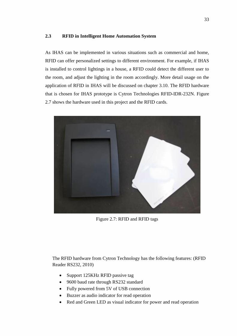
2.3 RFID in Intelligent Home Automation System
As IHAS can be implemented in various situations such as commercial and home,
RFID can offer personalized settings to different environment. For example, if IHAS
is installed to control lightings in a house, a RFID could detect the different user to
the room, and adjust the lighting in the room accordingly. More detail usage on the
application of RFID in IHAS will be discussed on chapter 3.10. The RFID hardware
that is chosen for IHAS prototype is Cytron Technologies RFID-IDR-232N. Figure
2.7 shows the hardware used in this project and the RFID cards.
Figure 2.7: RFID and RFID tags
The RFID hardware from Cytron Technology has the following features: (RFID
Reader RS232, 2010)
Support 125KHz RFID passive tag
9600 baud rate through RS232 standard
Fully powered from 5V of USB connection
Buzzer as audio indicator for read operation
Red and Green LED as visual indicator for power and read operation

34
Come with USB cable (for 5V power) and DB9 standard RS232 socket
(female), ready to be plug in to desktop computer with serial port
2cm reading range
Since this RFID reader from Cytron Technology is built to send data through
RS232, care must be taken if it is used to interface with other embedded
devices as the voltage level for communication is 8.5-10.5V, way above the
threshold of embedded devices.
2.4 User Interface Design
For IHAS, all the controls and information is presented on the computer screen so
that the users could navigate and control at the ease of their computers. However,
there are design guidelines that have to be followed to ensure the designed user
interface is easy to understand by all levels of users.
2.4.1 User Interface Design Guidelines
There are 6 principles in the fundamentals of user interface design, which are
structure principle, simplicity principle, visibility principle, feedback principle,
tolerance principle and reuse principle (Lucy A. D. Lockwood & Larry
L.Constantine).
The structural principle states that the UI should be designed consistently,
recognizable and apparent to users, grouping related things together and separate
unrelated things. The structure principle is the overall presentation of the user
interface architecture. The simplicity principle says an effective UI design should
make simple task easy to do and providing good shortcut that are meaningfully
related to longer procedure. Visibility principle emphasis on keeping the user

35
interface clean and simple, and try not to cramp too many unnecessary data in the
same screen. Feedback principle touch on the issue of notifying users about the
changes on user’s action that are relevant and of interest to the users through a clear
and concise and unambiguous language familiar to users. Tolerance principle gives a
certain flexibility that could reduce cost of mistakes by allowing undoing and
redoing, while also covers an input tolerance that is within user’s reasonable
interaction with the UI. Reuse principle states that we should design our UI to be
modular and could be reuse throughout the program, maintaining consistency with
purpose thus reducing the need the users to rethink and remember. (Scott W. Ambler,
1998)
2.4.2 Comparison between Visual Basic and Adobe Flash
Visual Basic and Adobe Flash is both suitable to design a Graphical User Interface
(GUI) for IHAS application. Visual Basic .NET is an object oriented computer
programming language by Microsoft. This differs from other object oriented
programming such as C++ with the ability to design a GUI at a short time. However,
the GUI is extremely simplistic and monotone that hardly attracts users to interact
with the program.
Adobe Flash on the other hand is created as a multimedia platform to add
interactivity, video and animation to webpages. More recently, it has evolved to a
crossover of multimedia and application over the net, making it rich internet
applications such as AIR Flash that is used to create web applications that does not
require webpages. Adobe flash contains an object oriented language call Actionscript.
Between these 2 applications, one that was built to entertain and designed to
capture people’s attention and one that offers a simple GUI to work with a certain
code, it is clear that Adobe Flash fits the need of an attractive and intuitive user
interface for IHAS application.

36
2.4.3 Adobe Flash with Serial Port Communication
Adobe flash is not without its drawback to use as the GUI for the IHAS. Natively,
Actionscript 3.0 does not support communication via serial port. However, a
workaround is found that is using a 3rd
party application call mdm Zinc 3.0. Zinc 3.0
offers Actionscript 3.0 extensions that allow a Flash to communicate with the serial
port.
Also, Zinc 3.0 also wraps a flash application into an executable file (EXE)
that will allow the designed product to run as a standalone application. Therefore, by
using Zinc 3.0, we have solved the issues of communicating with serial port that was
present on the native Actionscript 3.0 codes.
2.5 Software
2.5.1 Adobe Flash Professional CS5
Figure 2.8: Adobe Flash (Adobe Flash Professional CS5)
Adobe Flash Professional 5 is the latest version of flash authoring tool from Adobe
(Adobe, 2011). Originally established as a multimedia platform to add animation,
video, interactivity to webpages, it has positioned itself as a tool for “Rich Internet
Application” as it supports XML based FLA source files, actionscript editor, wide
content distribution, code snippets panel, a new text engine and video improvements
(Adobe Flash, 2011). For future expansion, it is a bonus that the same application
developed in Adobe Flash can be deployed in multiple areas, such as desktop
application, mobile phones, other electronic devices that run on Adobe Flash.

37
Actionscript 3.0 is a powerful object oriented programming that is highly
suitable to build rich internet application. Actionscript 3.0 is based on ECMAscript,
the international standardized programming language for scripting. We will be using
Actionscript 3.0 for smart control as it is flexible and powerful enough for our usage.
2.5.2 MDM Zinc 3.0.22
Figure 2.9: MDM Zinc 3.0.22 (Multidmedia Ltd, 2002)
Figure 2.9 shows MDM Zinc 3.0.22, which is used in the development of IHAS
application. This application is used to create, build and deploy real desktop
applications based upon Adobe flash, allowing us to turn an internet based
application into powerful desktop application (Multidmedia Ltd, 2002).
Zinc 3.0 has some of the following unique features, including extending
Actionscript with over 500 new events, methods and property (Multidmedia Ltd,
2002). For example, native Actionscript does not have the ability to retrieve/send
data through a communication, write files to local drives and exit an application
easily, by using mdm Zinc 3.0, these problems are solved.

38
2.5.3 Eterlogic Virtual Serial Ports Emulator 0.938.4.846
Figure 2.10: Eterlogic Virtual Serial Ports Emulator 0.938.4.846 (ETERLOGIC,
2007)
Figure 2.10 shows the Eterlogic Virtual Serial Port Emulator that creates virtual
serial ports that could be use to debug the software before try to communicate
directly with the hardware. Using Eterlogic Virtual Serial Port, 2 actual serial ports is
not needed to test the system.
2.5.4 AGGsoftware Com Port Data Emulator 2.7.1 build 622
Figure 2.11: AGGsoftware Com Port Data Emulator (AGGsoftware, 1999)
Figure 2.11 shows AGGsoftware Com Port Data Emulator which is a software that
generates a serial stream of data. The program can create a data flow, wrap it to data
packets (RS232, TCP/IP or UDP) and send to a port (AGGsoftware, 1999). This
software is used to receive/send data to IHAS application to emulate the data in/out
to the XBEE.

39
2.5.5 XCTU 32-bit ver. 5.1.4.1
Figure 2.12: XCTU 32-bit ver. 5.1.4.1 interface
Figure 2.12 shows X-CTU Software. X-CTU is the XBEE diagnostics software
which is invaluable in learning to communicate with XBEE. It offers web update to
the latest revision of the connected XBEE, and support for API and AT command
mode for XBEE. Also, it can change XBEE configuration without typing command,
although a built in terminal is available.
2.5.6 TightVNC version 2.0
Figure 2.13 : TightVNC Server Version 2.0
Figure 2.13 shows TightVNC version 2.0. TightVNC is a Virtual Network
Computing (VNC) server that allows remote connection into the computer. It will
stream the desktop to the connected client, providing real time control of the host
computer on a remote site.

40
CHAPTER 3
3 INTELLIGENT HOME AUTOMATION SYSTEM
3.1 Overview
Figure 3.1: Overall Block Diagram for Intelligent Home Automation System
Figure 3.1 shows the overall block diagram for IHAS. The IHAS Application which
resides in the PC connects with a XBEE through USB connection and communicates
wirelessly with end devices. For example, the light module receives command from
the IHAS to dim the lights to 50 %. IHAS Application also receives sensor data from
other modules such as occupancy sensor and light sensors.
RFID reader
module

41
3.2 Management Console
Figure 3.2: Block Diagram for Management Console
Figure 3.2 shows the management console block diagram. In the management
console, front end consists of UI to let users interact with IHAS easily. Sensor
algorithm is how IHAS will respond when sensor data is received by IHAS, whereas
communication backend protocol deals with how to communicate with the actual
devices. Data from personalized RFID settings could be stored on another subsystem.
3.3 User Interface for Main Menu
Figure 3.3: Management Console Main Menu

42
Figure 3.3 shows the management console homepage. Users could launch the
application and interact it as how they would with other application. The main menu
consists of different categories, each with their own subpage. Users could navigate
through different types of devices easily. If there is a power meter attached, the
power consumption could also be shown in the main menu.
3.4 User Interface for Lights
Figure 3.4: Lighting Control Page
The lighting control sub panel is shown in Figure 3.4. Users could see the status of
the lights currently, and turn on/off or dim up/down the lights in this panel. Through
the setting button the users could add lights, form lighting groups, delete lighting
from groups etc. Home button redirect the users back to the main page while back
button redirect users from the last page the users came from.
3.5 Automated Plug and Play Coordinator Setup
IHAS is designed to be user friendly and therefore all XBEE configurations should
be automated and requires no user intervention. First of such automated setup is to
configure the XBEE become a coordinator when it is plugged in to the computer.

43
Start
Plug in XBEE into
computer
Launch I2CS
application
XBEE
configured
before?
Bring users to
settings page
Bring users to
main menu
Run automated
setup on XBEE
configuration
Save configuration
on computer
User clicked into
Lights page
Open com port
based on saved
settings
Connection
established
between
coordinator and
end devices.
END
no
yes
Figure 3.5: Automated Setup of Coordinator for XBEE
Figure 3.5 shows how IHAS application is able to detect new XBEE devices and
bring users directly to settings page. After configuring the XBEE, IHAS application
should save the details of the configured XBEE into a file, and return users to main
page.
44
There are few challenges that are presented; one of them being how would
the computer know which COM ports is the XBEE? Different XBEE is attached and
listed as different COM ports in the computer’s device manager. Furthermore, if user
has more than one COM devices attached to computer, the IHAS have to find XBEE
from the attached devices.
As IHAS application is written in Actionscript 3.0, another hurdle that we
have to overcome is that Actionscript 3.0 does not permit file writing to local drive,
which is to computer. This is a design decision to avoid flash banners/ web games to
install malicious software into computer. Therefore, we have to find our way around
this limitation to enable this feature in IHAS.
3.6 Automated Scanning for End Devices Status
Similarly, if users have multiple end devices, IHAS application have to identify the
end devices automatically. For example, if the user has been using IHAS setup for
some time, and the user wishes to install new light fixture into the kitchen. IHAS
have to recognize the newly installed end device and its services provided. IHAS has
to show different settings and profile for different “services” offered by end devices.
For example, a ceiling fan is different from lights in terms of service provided and
configuration method to that particular device.
The steps IHAS should take to scan end devices:
I. Make sure coordinator and end devices are powered up
II. IHAS send “identify yourself” to all end devices in broadcasting mode
III. Wait incoming replies from all end devices.
IV. Time out after 5 seconds, Save all identified end devices to a file
V. Assigned different groups for different kinds of end devices, dimmable lights,
normal lights to lights, switches and sensors to inputs, ceiling fan to fan etc.
VI. Show the different groups and function in the IHAS application in an easy to
navigate and attractive manner.

45
During active operations, IHAS has to monitor the connection between end
devices and coordinator. For example, if the study room lights controller
experience communication breakdown, IHAS has to notify users that particular
end devices experience error and should stop users from interacting with that
particular end device until communications has been restored.
3.7 Remote Encryption Settings for End Devices
Security is especially important in wireless communications. XBEE supports
AES128 encryption; however, it is disabled at default. Therefore, steps have to be
taken to re-enable AES128.
I. Make sure coordinator and end devices are powered up
II. Prompt users to enter an encryption key
III. Send encryption key to end devices, enables AES128 encryption and
restart end devices at a delayed time* to take effect.
IV. Send command to coordinator to enable AES128 encryption and
restart coordinator.
V. Communication re-establish with AES128 encryption
* Coordinator has to restart first to enable end devices to connect to coordinator after
end devices restart.
One of the challenges in implementing this feature is how to remote configure all
connected XBEE, simultaneously. As mentioned in chapter 2.2.2.2, instead of
transparent operation, we have to use API mode to remote configure XBEE.
Another downside of this method is the master encryption key is sent out to
XBEE unencrypted, which means the encryption key is prone to be intercepted. This
is unavoidable as XBEE does not support session key.

46
3.8 IHAS Communications Format and Protocol
To communicate effectively between IHAS and end devices, a communication
format is established. The criteria of the protocol are compact and flexibility. Since
error detecting and correction is handled by the 802.15.4, the protocol does not need
error correction which increases complexity and processing time.
Table 3.1: IHAS Communication Protocol
Device Type Zone Number Data End Byte
3 bytes 2 bytes 2 bytes 2 bytes 3 bytes 1 byte
Table 3.1 shows the IHAS communication protocol. The first 3 byte dedicates to
what device type it is communicating, For example, Lights and Fans have different
Device parameters. Type is a communication type. For example, it could be type of
sensor/device type or message type. Zone defines how the devices are group,
Number is specified devices in a specific zone where data is the information payload
and end byte signifies end of packet.
Figure 3.6: IHAS Communication Protocol Example
Figure 3.6 shows an example of IHAS Communication protocol. The
protocol could be expended for future expansion. For example, user wanted to turn
on kitchen light which is on zone 3 to maximum intensity, IHAS application will
send the following frame to end device, “LIGLDZ3L1255#”.
Device
LIG (light)
SEN(sensor)
PWR (power)
FAN (fan)
Type
ST (seat sensor) OS ( occupancy sensor) LS (light sensor)
LD (LED)
LL (light level)
TS ( test ) AK (Acknowledge)
Zone
Z1
Z2
Z3
ZX
Number
L1
L2
L3
LX
Data
XXX
End Byte
#

47
IHAS also receive command from end devices in the same format. This
enables IHAS to know exactly which device is requesting/reporting data to IHAS.
3.9 RFID Integration in IHAS
RFID integration with IHAS is another method for users to change settings. Different
users with their own RFID tag could trigger different set of devices. For example,
imagine IHAS is implemented in an office floor with multiple rooms and cubicles.
When the office employee enters the front door, the RFID reader detects his
employee RFID tag, it triggers the light and air conditioner for his room and this
would cut down the need for human occupancy sensor. When more employees
started to come in, IHAS will detects and turn on the devices registered to the RFID
respectively. The same applies when the RFID is detected second time, instead of
turning on, IHAS will turn off the devices automatically. Figure 3.7 shows how
IHAS response when it detects a RFID card.
Figure 3.7: When IHAS Detects RFID
Before RFID cards can be used with IHAS, it has to first register with IHAS
RFID database. The database will store RFID number and the settings it would
change to the end devices. Figure 3.8 shows the flow of how a new RFID card could
be registered with IHAS.
Start
RFID detected by
I2CS, check with
database
Database has
information?
Unauthorized
card. No changes
to current system
Adjust settings
based on database
pre-configured
settings.
no yes

48
Figure 3.8: Registering new RFID card to IHAS database
3.10 Modular Design
IHAS is built with modularity in mind. This concept is shown in Chapter 3.2 for
software design; while modular design is used when design with the RFID reader
hardware. This practice is good to implement so that we could increase flexibility in
implementing IHAS without rework of the whole system. Figure 3.9 shows the
modular design of RFID hardware.
Start
Go to RFID
Setting page
yes
RFID number
retrieved?
Let user configure
the RFID card
access
Save RFID setting
to file
END
no

49
Figure 3.9: RFID Hardware Modular Design
3.11 Smartphone Controlled IHAS
Apart from using IHAS on the computer, users could also use extend their home
automation control using their smartphones. There are 2 ways of implementing this
method, which is using:
I. A dedicated smartphone client. This method requires a separate development
for the smartphone that enables the best user experience as it is coded
specifically for the smartphone. The smartphone application connects to
IHAS application through Wi-Fi network which enables users to seamlessly
control devices from their phone.
II. A VNC client. This method is inferior as compared to dedicated smartphone
client. This method requires a VNC server setup on the IHAS Application
computer and a VNC client on the smartphone. The VNC then streams the
desktop environment from the computer to the smartphone, enabling users to
control devices from their phone.
Although method 1 is superior as compared to method 2, method 2 is chosen as
the development time is shorter for the current version of IHAS.

50
3.12 Compatibility of IHAS with Commercial Products
IHAS is not just a proprietary method that only works with designated devices. IHAS
is built to works with both commercial systems and proprietary devices. We shall
discuss a potential design solution on energy savings for a university campus. The
design solution consists of the following features:
Air conditioner could be controlled by central management console and/or by
sensor deployed around the campus
Lighting system could be intelligently controlled by schedule based control,
occupancy based control or central management controlled.
Central monitoring system is needed to track energy usage and to fine tune
energy usage profile, which could be achieved by using XBEE and an easy to
manage control panel which integrates Heating Ventilation and Air
Conditioning (HVAC), lighting and device control.
The potential design solution could be implemented with commercial products
such as Schneider Electric range of energy management solution with IHAS. The
proposed design solution is strongly collaborated with (Wei, 2010).

51
Figure 3.10: Design Solution for Energy Savings On Campus

52
Referring to Figure 3.10, the power enters the circuit breaker and passes
through the power meter, which measured the power consumption of all the devices.
Then, the power is distributed to four channels 2A dimmer to power up the lights,
and to power up the motor and PLC. The C-bus multi sensor sense human occupancy
and ambient light level and relays the information to C-bus network while C-Bus
LCD input is used for local control for lighting and HVAC control. The Pacal
automation control also communicates with the local processing module via another
RS232 connection. All sensor data and device status is transmitted via a XBEE
transceiver for further processing.
The PACAL automation controller enables the integration of IHAS with C-
Bus network. From there, we are able to get sensor data, power usage from power
meter, lights status from respective dimmer and display on the same screen, which is
on the IHAS management console.
If the system is integrated with classroom time management system, teachers
can book time for specific lecture class that reduces conflicts among lecturer
regarding extra class’s venue. Also, the management console not only be able to
control lighting and HVAC system, it could also remotely shutdown, restart or sleep
unused pc through Wi-Fi. Figure 3.11 shows how could the management console for
this energy management console looks like.
Figure 3.11: Design Concept on management console

53
CHAPTER 4
4 IMPLEMENTATION OF IHAS AND OUTCOMES
4.1 Sending Data through a Com Port
4.1.1 Implementation
The first step in this system is to send a data through Actionscript 3.0 using mdm
zinc 3.0 scripts. Since IHAS uses sliders frequently, this test uses sliders to test. An
Adobe Flash file with the following code is created:
//Actionscript initialization
import fl.controls.Slider;
import fl.events.SliderEvent;
import mdm.*;
mdm.Application.init(this);
//initialization ends
//setup of event listener
s.addEventListener(SliderEvent.CHANGE,
announceChange);
//end of event listener
Initialization of actionscripts,
importing relevant library and
extensions
Event listener that will
be triggered if slider
value has change

54
//Initialization of com ports
var availablePorts:String = mdm.COMPort.ports;
mdm.Dialogs.prompt(availablePorts);
mdm.COMPort.open(2, 9600, 8, "N", 1, "OFF");
//Initialization of com ports end
//Com port functions
mdm.COMPort.onCOMPortData =
function(myObject:Object){
mdm.Dialogs.prompt(myObject.data);
};
//Com port functions end
//functions calls
function announceChange(v:SliderEvent):void {
mdm.COMPort.send(v.target.value);
}
//end function call
After setting up the flash, this application is compiled to a native flash file, .SWF.
After that, the SWF file is rebuilded using Zinc 3.0 into an EXE excutable file that
includes all the neccesary mdm scripts library file, as shown in Figure 4.1.
Figure 4.1: Zinc 3.0
MDM Zinc 3.0
scripts that initializes
the com port
Com port function call
in the event of data
received
Sends the data out to
the com port when the
slider value has change

55
When the build is completed, virtual com port and com port data emulator is setup as
shown in Figure 4.2 and Figure 4.3.
Figure 4.2: Virtual Serial Com port
Figure 4.2 shows that COM2 and COM3 ports has been opened and is linked
together. Note that our test application is connected to COM2.
Figure 4.3: Com Port Emulator Setup

56
Figure 4.3 shows the setup of Com port emulator which is connected to COM3 and is
running at the same baud rate, same encoding scheme with the program.
Figure 4.4: Configuring Data Emulator to Send Data
Figure 4.4 shows how to configure a com port data emulator to send text data to the
test application.

57
4.1.2 Outcome
Figure 4.5: Scanning Ports
Figure 4.5 shows initial port scan of free com ports before starting of com port
emulator returns 3 com ports, 1 physical com port and 2 virtual com ports, COM2
and COM3.

58
Figure 4.6: Started Com Port Emulator Before Starting Up Application
Figure 4.6 shows that COM3 has been connected to Com Port Data Emulator before
starting up the application, resulting a returned of free com port of only COM1 and
COM2.

59
Figure 4.7: Result from Application Testing (Send)
Figure 4.7 show the application is able to send a continuous stream of change value
through a com port. Since the slider value has a maximum value of 10 and minimum
value of 0, the Figure show a transition from 0 to 5 translate into half the slider bar.

60
Figure 4.8: Result from Application Testing (Receive)
Figure 4.8 shows that when the data emulator sends a string of text file to the
application, the application responds by showing out on a dialog, which is a
preprogram actions.

61
4.2 Design a User Friendly UI
4.2.1 Implementation
Using Adobe Flash, we try to create a UI following the design guidelines that has
been discussed on Chapter 2.4.
4.2.2 Outcome
Figure 4.9: Main Menu
Figure 4.9 shows the main menu of IHAS application which is named “Home Energy
Management Console”. The main menu has 4 options, which are Devices, Option,
Help and Exit. Devices will bring users to device control such as lighting control.
Option will bring users to setup the XBEE. Help is to assist user in using this
program while Exit exits the program.

62
Figure 4.10: Lights Control Page (full)
Figure 4.10 shows the lights control page. The lights are divided into sections
according to the zones. Instead of naming the sections Zone 1 or Zone 2, users could
rename them into meaningful phrases to them, such as Kitchen, Living Hall and
Toilet. Below the zone description is the ambient light level detected by the light
level sensors. The slider controls individual lighting where green glow around the
border of the light is an indication that the light is on.
When the communication breakdown between a particular zone and the
coordinator, warning is displayed as showed in Figure 4.10 and changes could not be
made on the particular zone until communications has been restored.
The buttons on the bottom of the page are back, home and next. These
buttons help users to navigate through devices.

63
Figure 4.11: Lights Control (desktop mode)
Figure 4.11 shows the lights control on desktop mode, where users could use their
computer and interact with the devices at the same time. In desktop mode, IHAS lose
the ability to configure the XBEE. Therefore, users have to run IHAS full application
once before they could launch IHAS desktop mode.
64
4.3 Automated Setup for XBEE Coordinator
4.3.1 Implementation
START
Scanned for
available COM
Ports
i = 1
i<= number of
COM ports?
Open COM Port I
and send “+++”
“OK” received
within 2
seconds?
i++
No XBEE found
Send
ATSH,SL,DH0000
,DLFFFF,CE1,A27
,NIMASTER,WR,
CN
Write Programmed
XBEE Serial number
to
comportsetting.xml
END
All commands
return “OK”?
yes
no
yes
yes
no
no
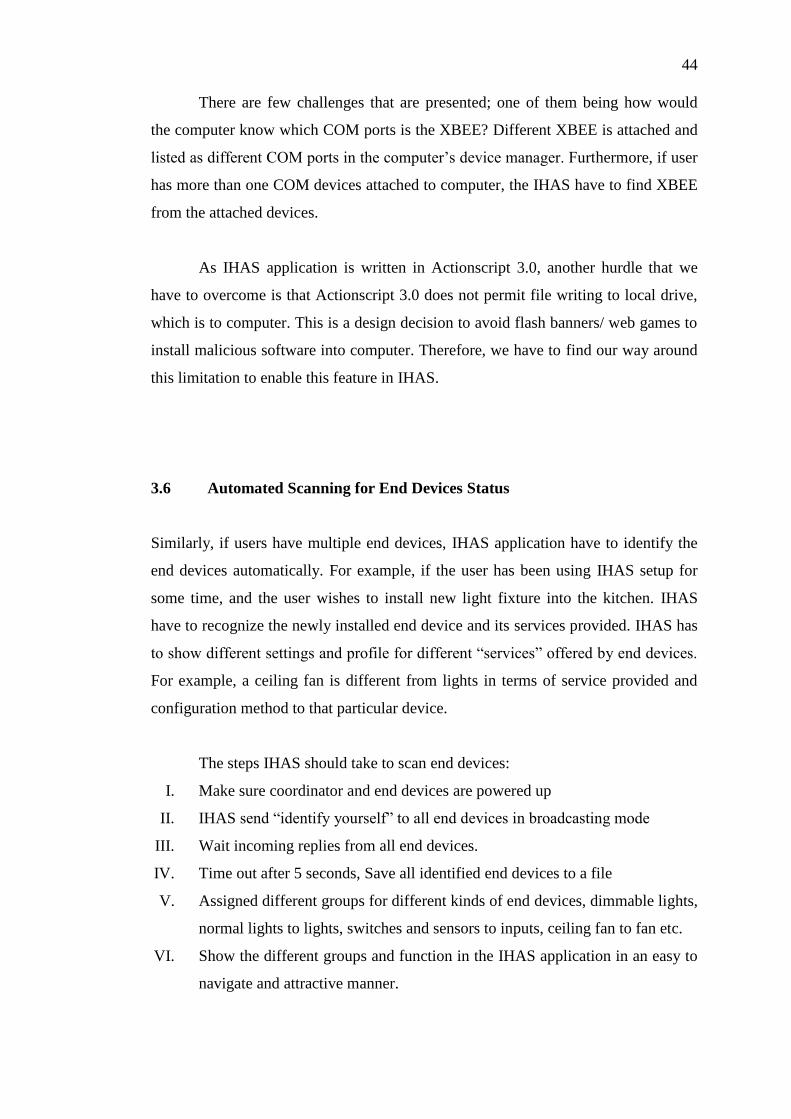
Figure 4.12: Flow chart to configure XBEE settings automatically
This section shows how to locate XBEE
from other COM ports attached to a
computer. If the attached COM port is
XBEE, it will response with “OK” when
it is input with “+++”. “+++” is to enter
the command mode of XBEE.
This section setup the XBEE.
SH – Retrieve Serial number high
SL – Retrieve Serial number low
DH – Set to broadcasting mode
DL – Set to broadcasting mode
CE – Coordinator Enable
A2- Coordinator Settings
NI – Name Identifier
WR- Write settings to ROM
CN – Exit Command mode

65
Figure 4.12 shows how to scan for an attached XBEE and related settings to program
a XBEE into a coordinator. As discussed in Chapter 2.2.2.1, “+++” is used to enter
AT command mode of the XBEE. If the com port attached is polled with “+++”,
XBEE will return “OK”, which is used to identify that specific port is attached to a
XBEE.
4.3.2 Outcome
Figure 4.13: Plug and Play XBEE Coordinator Easy Setup
Figure 4.13 shows the visual indicator of the XBEE configuring process, where
IHAS get the 16-bit unique address from XBEE, configure it to broadcast mode,
enable coordinator mode in XBEE, change coordinator settings to allow channel
assignment, allow panID assignment and allows association. These settings are used
to allow end device to connect to the coordinator.

66
4.4 Automated Scanning for End Devices Status
4.4.1 Implementation
START
Open COM port
with the settings in
comportsetting.xml
and send “+++”
yes
no
“OK” received
within 2
seconds?
Send “ATND”
Incoming data is
stored in string
variable
incomingdata
5 seconds
passed?
Break
incomingdata into
array for different
parameter
Save end devices
MY,SH,SL,DB,NI
to endnodes.xml
END
XBEE coordinator
not found
yes
no
Figure 4.14: Steps to Detect and Save End Devices to Database
ND – Node Discover command.
Broadcast to all end devices
End device will send back information,
stored in a string.
Every end device will send data with
structure as below:
FFFF<CR> 16bit address
13AA00<CR> 64bit address high
403BFBC9<CR> 64bit address low
24<CR> Receive signal (dB)
LIGHT<CR> Identifier name
<CR>
<CR>
Write all received data into xml file name
endnodes.xml

67
Figure 4.14 shows the flow chart on how to scan end devices and keep the data into a
data file. When the Node Discover is sent to the end devices, all the end devices will
return their 16 bit short address, 64 bit unique address and also the identifiers name.
The coordinator also reports the received signal strength of that particular end device.
All these data is stored in a data file that is used for IHAS to recognize which XBEE
controls which device from the node identifier name.
4.4.2 Outcome
Figure 4.15: End Device Scanning
Figure 4.15 shows the IHAS will report how many detected XBEE after a 5 seconds
timeout. At the same time, IHAS will write to a xml file with the acquired data from
the end devices. An example is shown in Figure 4.16.
Figure 4.16: endnodes.xml Datafile

68
4.5 Remote Encryption Settings for End Devices
4.5.1 Implementation
START
Prompt user for
encryption key
Open COM port with
the settings in
comportsetting.xml
and send “+++”
“OK” received
within 2
seconds?
XBEE coordinator
not found
Send
ATAP1,WR,CN
Send API
command based
on encryption key
to end devices
Send API
command to
change encryption
key to coordinator
Send API
command to revert
coordinator to
transparent
operation
END
no
yes
Figure 4.17: Remote Encryption Setting
Change transparent mode to API mode

69
Figure 4.17 shows how to remotely change an encryption key and enable AES128
encryption. API mode is needed as transparent operation does not support remote
configuration. Once the user keys in the encryption key, IHAS will process an API
frame before it could be sent out as listed in Chapter 2.2.2.2. An example of sending
an API command of enabling an encryption key of end devices having a short
address of FFFE will be as shown in Figure 4.18:
7E 00 10 17 01 00 00 00 00 00 00 FF FF FF FE 02 45 45 01 61
Start Delimiter
Frame length in Hexadecimal
API identifier for remote configuration
Acknowledgment
64 bit unique address ( configured to use 16 bit short address in this case)
16 bit short address
Apply changes after received command flag
AT command in hexadecimal
Parameter
Checksum
Figure 4.18: API Frame Example

70
4.5.2 Outcome
Figure 4.19: Security Setup
Users are prompted to key in the 32 Hex character encryption key as shown in Figure
4.19. However, when the encryption key is sent, it is unencrypted. Potential
interception of encryption key is possible within the timeframe of sending encryption
key to the end devices.
4.6 RFID Integration with IHAS
4.6.1 Implementation
Using RFID reader as mentioned in Chapter 3.9, modifications have to be made to
interface with XBEE. Voltage level conversion chip is required as discussed in
Chapter 2.3.

71
Figure 4.20: Modular design of RFID Conversion Circuit
Figure 4.20 shows a modular design in RFID conversion circuit design. 24V input
header is located on the lower right of the circuit. This RFID is powered by 240V
and the voltage conversion and regulation circuit is a commercially available power
supply. XBEE can be detached quickly as it is attached to the header on the board.

72
4.6.2 Outcome
Figure 4.21: RFID Conversion Circuit and Power Conversion and Regulation Circuit
Figure 4.22: Complete RFID Hardware
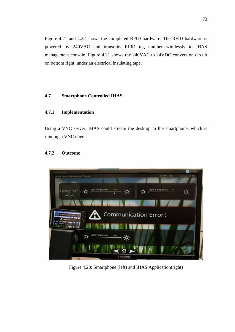
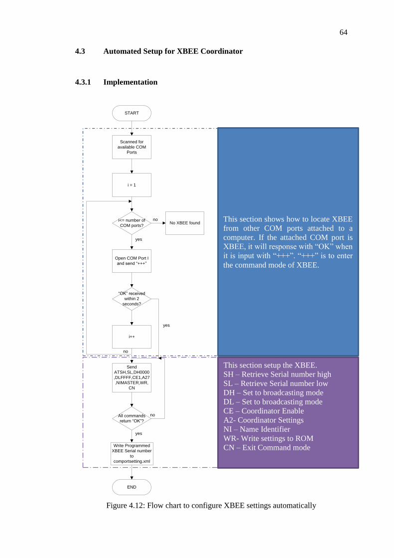
73
Figure 4.21 and 4.22 shows the completed RFID hardware. The RFID hardware is
powered by 240VAC and transmits RFID tag number wirelessly to IHAS
management console. Figure 4.21 shows the 240VAC to 24VDC conversion circuit
on bottom right, under an electrical insulating tape.
4.7 Smartphone Controlled IHAS
4.7.1 Implementation
Using a VNC server, IHAS could stream the desktop to the smartphone, which is
running a VNC client.
4.7.2 Outcome
Figure 4.23: Smartphone (left) and IHAS Application(right)

74
Figure 4.24: Smartphone Streaming IHAS Application
Figure 4.23 and Figure 4.24 shows how we could extend IHAS control to a
smartphone. The screen resolution and refresh rate is not optimized. This problem
could be fixed if native IHAS client is developed for the smartphone instead of
running VNC through a Wi-Fi network.

75
4.8 Design Solution based on commercial products
4.8.1 Implementation
3 V1
4 V2
5 V3
6 VN
14 |1+
15 |1-
Power Logic PM700
4 Channel Dimmer
Power Logic PM 750
TWDLCAA24DRF
TWDLCAA24DRF
TM2AMM3HT
3 Phase Blower
Solid State Temperature
4 x 15W Incandescent Bulb
Temperature Setting Signal (Analogue)
Human
Occurrence Signal
(Digital) RFID Signal (Digitial)
Temperature Signal
(Analogue)
LED Indicating Lights (OHP,
Projector and Computer)
Hard Wire
Communication
LNG
General InputAnalogue Output
Figure 4.25: Electrical Wiring diagram for HVAC and Lighting Control System
Prototype
Damper

76
Figure 4.25 shows the Electrical Wiring diagram for HVAC and Lighting Control
System Prototype. As this is a prototype of the design solution on integrated control
system, there is some modification on the initial design solution to focus the attention
on integrating HVAC and Lighting Control. Hence, the central management console,
XBEE and PACAL automation controller is not included in this first prototype as it
is a later stage integration to the HVAC and Lighting Control System. The bill of
material that is shown in Figure 4.25 is listed in Table 4.1.
Table 4.1: Bill of Material for Lighting and HVAC control prototype
Item Part
C-BUS 5G KEY INPUT, SATURN DLT,LCD 5085DL GF
C-BUS GENERAL INPUT E5504GI
4CHANNEL DIMMER 240V-200mA POWER SUPPLY L5504D2A
COMBINED PIR & LIGHT LEVEL SENSOR 5753PEIRL
C-BUS ANALOGUE OUTPUT L5504AMP
ATV312 ALTIVAR ATV312H037M2
PM750 POWER METER PM750MG
RJ45 - MINI DIN CABLE TSXCRJMD25
USB - RS485 CONVERTER TSXCUSB485
TWIDO ANALOGUE MODULE TM2AMM3HT
RFID OSISENSE STATION XG XGCS4901201
RFID CARDS XGHB90E340
RFID CABLE TCSMCN1F2
BASE UNIT AC,14 IN DC,10 OUT RLY,TBK TWDLCAA24DRF
MOD-BUS ADAPTER TWDNAC485T

77
The prototype is divided in 2 parts, lighting control and HVAC and RFID control.
4.8.1.1 Lighting Control
Figure 4.26(A): Lighting Control Prototype
Figure 4.26(B): Enclosure for Multi Sensor
Figure 4.26 (A) shows the lighting control prototype while Figure 4.26 (B) shows the
enclosure for multi sensor. The prototype is divided into two parts as they are two
very different systems. The Lighting Control system is based on commercial
products produces by Clipsal, whereas the HVAC and RFID control is an industrial
solution by Telemacanique. However, we managed to integrate two different
solutions working as one system. We shall begin to discuss our system with lighting
control system.
The lecture hall is divided into four zones, where zone one is the teaching
area. Also, there are three LED that represents OHP, Computer and Projector
respectively. There is also and RFID reader that is located at the entrance of the
lecture hall, which is shown in the bottom left corner of the lighting control prototype.
Each zone is light up by an incandescent bulb. There is also a control box to simulate
daylight and shows how the light and occupancy sensor reacts to sudden change in
light intensity.
(A)
(B)

78
Clipsal four channel dimmer L5504D2A, Clipsal Analogue Output
L5504AMP, Clipsal C-Bus 5G Key Input 5085DLGF, Clipsal C-Bus general Input
and Clipsal C-Bus Occupancy and Light level Multi Sensor 5753PEIRL is connected
to C-Bus network. By connecting C-Bus network, the connected devices could
communicate with each other.
The four channel light dimmer activates the lights according to preset
luminance based on ambient light level when the multi sensor detects human
occupancy. Simultaneously, the analogue output will sends signal to the HVAC
control which will turn on the air conditioner system for the particular lecture hall. C-
Bus general input unit is used to accept RFID signals from the PLC as there is no
RFID reader available from Clipsal.
RFID settings not only control the light’s intensity, it also control the devices
that is able switched on based on lecturer teaching style. In this prototype, three types
of teaching style are created, OHP, Projector and All on. Therefore, based on the
RFID detected upon lecturer entering the lecture hall, changes will be made
automatically to suit that particular lecturer.
Table 4.2: Preset RFID Configuration
Preset modes Lights configuration Projector and
screen
OHP
OHP mode Front row off, 2nd
row 50 %
intensity,
Others on
Off On
Projector mode Front row 50 %, 2nd
row 70 %
intensity,
Others on
On Off
All on All lights full intensity Off Off
Table 4.2 shows preset RFID Configurations. In OHP modes, the front rows
of lights will be switched off to increase the clarity of the OHP projector. At the same
time, the projector is turned off to save power. The lecture PC is configured to sleep,
minimizing the power consumed when it is not in used. For lecturer who uses
projector, the PLC will control the motorized projector screen and turn on the
79
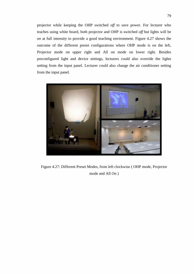
projector while keeping the OHP switched off to save power. For lecturer who
teaches using white board, both projector and OHP is switched off but lights will be
on at full intensity to provide a good teaching environment. Figure 4.27 shows the
outcome of the different preset configurations where OHP mode is on the left,
Projector mode on upper right and All on mode on lower right. Besides
preconfigured light and device settings, lecturers could also override the lights
setting from the input panel. Lecturer could also change the air conditioner setting
from the input panel.
Figure 4.27: Different Preset Modes, from left clockwise ( OHP mode, Projector
mode and All On )

80
4.8.1.2 HVAC and RFID Control
Figure 4.28: HVAC Prototype
The HVAC prototype consists of 3 sections, the air duct, blower, and a damper as
shown in Figure 4.28. Air duct is the air channel that the cold air passes from the Air
Handling Unit (AHU) to every lecture hall, and each individual lecture hall controls
the air flow via a damper. Figure 4.28 shows the HVAC prototype that is use to show
the blower in AHU and damper control in the HVAC system. The blower speed and
the damper opening will be determined by the PLC which gets its signal from C-Bus
network.
The respective hardware needed in HVAC control is Telemacanique ATV312
Altivar ATV312H037M2 variable speed drive 3 phase motor driver, Twido Base unit
TWDLCAA24DRF which is a PLC, Twido Analogue module TM2AMM3HT to
expand the PLC unit to accept analogue input.
From Figure 4.25, PLC receives signals from C-Bus analogue output unit on
the following occasions:
C-Bus Multi sensor detects human occupancy, C-Bus analogue sends signal
to turn on air conditioner.
C-Bus input panel changes temperature settings, C-Bus analogue sends signal
for air flow regulation.
C-Bus Multi sensor detects human occupancy, C-Bus analogue sends signal
to turn off air conditioner after certain period.

81
Also, RFID receiver is also connected to the PLC in this prototype. When the
RFID is scanned and detected, the PLC will send signal to the C-Bus General Input
to switch between various modes.
To keep track of the energy savings, continuous monitoring is essential.
Therefore, PM750MG Power Meter is installed in the mains to measure and track
energy consumption of our prototype.
4.8.2 Outcome
Through various experiment and research, it is found that the HVAC and Lighting
Control System is able to save 44 % in lighting control and 60 % in HVAC control.
This translates into massive savings if it is implemented UTAR FES campus. By
implementing the proposed HVAC and Lighting Control System, UTAR FES will
achieve return on investment in 3 years with a total savings up to RM250,000 a year.
Detailed calculations on the acclaimed savings are available in Appendix B.
The massive savings, simple solution of the HVAC and Lighting Control
System is awarded 1st Runner Up in Schneider Electric Green the World @ My
Campus University Challenge 2010 is as shown in Figure 4.29.
Figure 4.29: The Lighting and HVAC Control System Prototype

82
Figure 4.30 shows the Lighting and HVAC Control System with updated
prototype, showcasing in IEEE STUDENT Conference 2010. The HVAC and
Lighting Control System is awarded Best Exhibitor award.
Figure 4.30: IEEE STUDENT Conference 2010 Best Exhibitor Award Winner, From
left, MAK KWAN WUEY, LIU CHEE WEI, GAN YU HAN.

83
CHAPTER 5
5 CONCLUSION AND FUTURE IMPLEMENTATION
As a conclusion, Integrated Home Automation System allows users to interact with
physical devices from their computer. Also, IHAS has established a common method
of communication for device manufacturer. IHAS is able to automate coordinator
setup, which is a plug-and-play feature to the end users. This simplifies the home
automation process as IHAS does not require users to manually configure the XBEE.
Also, IHAS has the option to run on desktop mode, which integrates IHAS to
the desktop of a Windows machine, enabling users to interact with IHAS easily and
seamlessly while using other applications. Both full application mode and desktop
mode features an attractive and intuitive design that aims to being home automation
technology easy to operate by anyone.
IHAS operates at AES128 encryption mode, ensuring the security of the users’
home automation system. Also, users could also use RFID to control their devices
using IHAS. Furthermore, users are also given the option to remote control IHAS via
Wi-Fi network using a smartphone with VNC client installed.
Integration of IHAS with commercial system is planned for future
development, as well as developing a dedicated smartphone client for IHAS that
offers better user experience. Overall stability of IHAS also needs to be enhanced.
Also, IHAS could also provides time management in future releases. Lastly, more
devices support and updated and more streamlined user interface is also planned for
IHAS.

84
REFERENCES
Adobe. (2011). Retrieved August 27, 2010, from Adobe Flash Professional CS5:
http://www.adobe.com/products/flash/
Adobe Flash. (2011). Retrieved August 27, 2010, from Flash Professional for web
application development: http://www.adobe.com/products/flash/web/
AGGsoftware. (1999). AGGsoftware, TECHNOLOGY AT YOUR SERVICE.
Retrieved August 27, 2010, from COM PORT DATA EMULATOR:
http://www.aggsoft.com/com-port-emulator.htm
Alliance, Z.-W. (2004). Z-Wave Alliance. Retrieved August 27, 2010, from Z-Wave
Alliance: http://www.z-wavealliance.org/modules/AboutUs/
Cotter, K. (2008, November). ONE-NET. Retrieved from ONE-NET:
http://www.one-
net.info/index.php?option=com_content&view=article&id=25:nodes&catid=
16:tidbits&Itemid=20
Cotter, K. (2008, November). ONE-NET FAQ. Retrieved August 27, 2010, from
ONE-NET: http://www.one-
net.info/index.php?option=com_content&view=article&id=24:power&catid=
16:tidbits&Itemid=20
Cotter, K. (2008, November). ONE-NET Topology. Retrieved August 27, 2010, from
ONE-NET: http://www.one-
net.info/index.php?option=com_content&view=article&id=27:topology&cati
d=16:tidbits&Itemid=20
ETERLOGIC. (2007). ETERLOGIC.COM. Retrieved August 27, 2010, from Virtual
Serial Port Emulator: http://www.eterlogic.com/Products.VSPE.html
Harrop, P. (2010). ZigBee for Energy Harvesting and Very Low Power. IDTechEx
Energy Harvesting and Storage conference, (pp. 1-2). France.
Hernandez, J. C., & lsasi, P. (2004, June). New results on the genetic cryptanalysis of
TEA and reduced-round versions of XTEA. 2004 Congress on Evolutionary
Computation CEC2004, 2, 2128.
Kanellos, M. (2010, July 3). Intel’s Cure for Home Energy Management: Answering
Machines. Retrieved August 25, 2010, from WIRED:
http://www.wired.com/epicenter/2010/07/intel%E2%80%99s-cure-for-home-
energy-management-answering-machines/?intcid=postnav
Kinney, P. (2003). Zigbee Technology: Wireless Control that Simply Works.
Communication Design Conference, (pp. 2-4).

85
(n.d.). In Lucy A. D. Lockwood, & Larry L.Constantine, Software for Use: A
Practical Guide to the Models and Methods of Usage-Centered Design (pp.
45-46). US: Addison-Longman, Inc.
Meshnetics Team, A. C. (2009). Atmel Corporation. Retrieved from ZIGBEE FAQ:
http://www.meshnetics.com/zigbee-faq/#14
MeshNetics Team, A. C. (2009). MeshNetics. Retrieved April 10, 2011, from
ZIGBEE FAQ: http://www.meshnetics.com/zigbee-faq/#33
Multidmedia Ltd. (2002). Multidmedia Ltd. Retrieved August 26, 2010, from Zinc™
3.0 - Rapid Application Development for Adobe® Flash:
http://www.multidmedia.com/software/zinc/
ONE-NET. (n.d.). Retrieved from About ONE-NET: http://www.one-
net.info/index.php?option=com_content&view=section&layout=blog&id=1&
Itemid=2
RFID Reader RS232. (2010). Retrieved April 10, 2011, from Cytron Technologies,
Robot Head To Toe:
http://www.cytron.com.my/viewProduct.php?pid=EyQkLxQPGT0JJicFBzk4
E5Kg2NOpoGCSzAPYwnQ/jLQ=
Scott W. Ambler. (1998). Best Practices for Software Development. Retrieved
August 27, 2010, from User Interface Design Tips, Techniques, and
Principles: http://www.ambysoft.com/essays/userInterfaceDesign.html
Technology, S. (2005, August). Retrieved from Insteon, a smartlabs technology:
http://www.insteon.net/about-whitepapers.html
Thonet, G., Allard-Jacquin, P., & Colle, P. (2008). ZigBee – WiFi Coexistence.
White paper and Test Report, Innovation Department, France.
Wei, L. C. (2010). Smart Lighting System: Modular Intelligent Control System.

86
XBEE Command List Appendix A

87

88

89

90

91
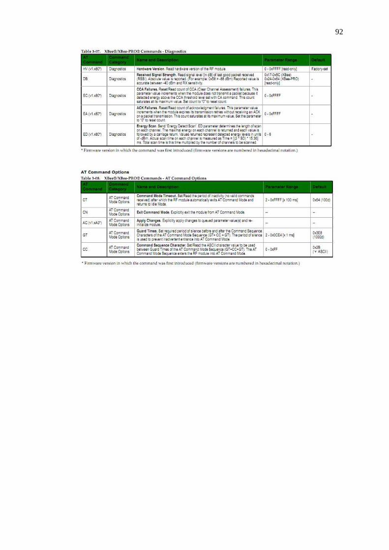
92

93
Baseline Data and Energy Savings Calculation Appendix B

94

95

96

97

98

99