INTELLECTTM Software Package...7 1 INTRODUCTION 1.1 Purpose and structure of the guide The INTELLECT...
167
AxxonSoft INTELLECT TM Software Package Installing and configuring security system components guide Version 1.0.0 Moscow 2012
Transcript of INTELLECTTM Software Package...7 1 INTRODUCTION 1.1 Purpose and structure of the guide The INTELLECT...

AxxonSoft
INTELLECTTM
Software Package
Installing and configuring
security system components guide
Version 1.0.0
Moscow 2012
2
Contents
CONTENTS ................................................................................................................................................ 2
1 INTRODUCTION .............................................................................................................................. 7
1.1 Purpose and structure of the guide ........................................................................................................... 7
1.2 Purpose of the INTELLECT™ software package .......................................................................................... 7
2 INSTALLATION OF SECURITY SYSTEM COMPONENTS ...................................................... 8
2.1 Assembly and installation of video surveillance subsystem hardware ...................................................... 8
2.1.1 Installing video capture cards into computer case ...................................................................................... 8
2.1.2 Installing drivers for video capture cards ................................................................................................... 10
2.1.3 Testing installation of drivers for video capture cards .............................................................................. 14
2.1.4 Testing installation of drivers for video capture cards using the Codereader.exe utility .......................... 16
2.2 Installing the expansion card for analog video out .................................................................................. 17
2.3 Connecting the hardware performance tester ......................................................................................... 19
2.3.1 Connecting the Watchdog hardware performance tester ......................................................................... 19
2.3.2 Connecting the USB Watchdog hardware performance tester ................................................................. 22
2.4 Connecting DI/DO cards .......................................................................................................................... 24
2.4.1 Connecting 4/4 and 16/4 DI/DO cards ....................................................................................................... 24
2.4.2 Connecting 4/4 DI/DO (low profile) cards .................................................................................................. 29
2.4.3 Connecting SL USBIO («4x4», «16x8», «24x4») cards ................................................................................ 30
2.4.4 Connecting MO USBIO 4x4 cards ............................................................................................................... 31
2.4.5 Connecting DI/DO (Stretch) ....................................................................................................................... 33 2.4.5.1 Connecting DI/DO cards to Stretch (VRC6004, VRC6008, VRC6416) cards ........................................................ 33 2.4.5.2 Connecting DI/DO cards to Stretch VRC7008L card ........................................................................................... 34
2.5 Connecting MO USBIO 4х4 external module ........................................................................................... 35
2.6 Assembly and installation of audio subsystem hardware components ................................................... 35
2.6.1 Supported sound cards and other audio input devices ............................................................................. 36
2.6.2 Options for increasing the number of audio input channels when standard sound cards are used ......... 36
2.6.3 Installing audio input devices..................................................................................................................... 36
2.6.4 Installing microphones and loud speakers ................................................................................................. 36
2.7 Connecting PTZ units and control panels ................................................................................................. 37
2.8 Connecting and configuring network devices .......................................................................................... 37
3 CONFIGURING SECURITY SYSTEM COMPONENTS IN INTELLECT™ SOFTWARE .....39
3.1 Configuring video capture cards in INTELLECT™ software........................................................................ 39
3.1.1 Video subsystem configuration ................................................................................................................. 39 3.1.1.1 Creating and configuring the Video capture card object ................................................................................... 39 3.1.1.2 Creating and configuring the Camera object ..................................................................................................... 41
3
3.1.1.3 Configuring the analog video output ................................................................................................................. 43 3.1.1.4 Configuring Stretch video capture card ............................................................................................................. 45 3.1.1.5 Configuring HikVision video capture card .......................................................................................................... 47
3.1.2 Audio subsystem configuration ................................................................................................................. 47 3.1.2.1 Creating and configuring the Audio card object ................................................................................................ 47 3.1.2.2 Creating and configuring the Microphone object .............................................................................................. 49
3.1.3 Initial configuration wizard ........................................................................................................................ 51
3.1.4 Configuring the Watchdog hardware performance tester ........................................................................ 53
3.2 Configuring IP devices ............................................................................................................................. 55
3.2.1 General information about IP devices ....................................................................................................... 55
3.2.2 Configuring video acquisition from IP devices ........................................................................................... 55
3.2.3 Configuring audio acquisition from IP devices ........................................................................................... 56
3.2.4 IP Wizard .................................................................................................................................................... 56
3.2.5 Features of IP device configuration ........................................................................................................... 59 3.2.5.1 Features of Beward IP cameras configuration .................................................................................................. 59 3.2.5.2 Features of Panasonic IP devices (i-Pro series) configuration ............................................................................ 59 3.2.5.3 Features of TrendNet IP device configuration ................................................................................................... 60 3.2.5.4 Features of Pelco Spectra IV IP device configuration ......................................................................................... 60 3.2.5.5 Features of AEBELL IP device configuration ....................................................................................................... 60 3.2.5.6 Features of Dynacolor IP device configuration .................................................................................................. 60 3.2.5.7 Features of Stream Labs IP device configuration ............................................................................................... 61 3.2.5.8 Features of Cisco IP device configuration .......................................................................................................... 62 3.2.5.9 Features of Mobotix IP device configuration ..................................................................................................... 62
3.3 Configuring DI/DO devices in INTELLECT™ software ................................................................................ 63
3.3.1 Creating and configuring the Relay system object .................................................................................... 63
3.3.2 Creating and configuring the Sensor system object .................................................................................. 64
3.3.3 Configuring DI/DO expansion cards ........................................................................................................... 65 3.3.3.1 Connecting relays ............................................................................................................................................... 65 3.3.3.2 Connecting sensors via 4/4 DI/DO card ............................................................................................................. 68 3.3.3.3 Connecting sensors via 16/4 DI/DO card ........................................................................................................... 70
3.3.4 Configuring DI/DO expansion cards (low profile) ...................................................................................... 73 3.3.4.1 Connecting relays ............................................................................................................................................... 73 3.3.4.2 Connecting sensors ............................................................................................................................................ 74
3.3.5 Configuring SL USBIO card ......................................................................................................................... 76 3.3.5.1 Connecting relays ............................................................................................................................................... 76 3.3.5.2 Connecting sensors ............................................................................................................................................ 76
3.3.6 Configuring MO USBIO 4х4 device ............................................................................................................. 76 3.3.6.1 Connecting relays ............................................................................................................................................... 76 3.3.6.2 Connecting sensors ............................................................................................................................................ 77
3.3.7 Configuring DI/DO (Stretch) cards ............................................................................................................. 78 3.3.7.1 Connecting relays ............................................................................................................................................... 78 3.3.7.2 Connecting sensors ............................................................................................................................................ 79
3.3.8 Configuring sensors and relays connected via IP devices .......................................................................... 79
3.4 Telemetry configuration .......................................................................................................................... 80
3.4.1 Use of PTZ devices in the digital video surveillance system ...................................................................... 80
3.4.2 Priorities of PTZ control ............................................................................................................................. 81
3.4.3 PTZ device (telemetry) configuration ........................................................................................................ 83 3.4.3.1 Sequence of PTZ device configuration ............................................................................................................... 83 3.4.3.2 Configuration of Server ports and remote workplace for PTZ connection ........................................................ 83 3.4.3.3 PTZ device configuration in the INTELLECT™ software ...................................................................................... 84
3.4.4 Telemetry control panel configuration ...................................................................................................... 85
4
3.4.4.1 Features of BOSCH 12c-KBD-Digital control panel configuration and operation ............................................... 86 3.4.4.2 Features of Axis T8310 control panel configuration and operation ................................................................... 88
3.4.5 PTZ IP cameras configuration..................................................................................................................... 91
3.4.6 Telemetry panel configuration .................................................................................................................. 91
3.4.7 Creation and configuration of the Operator dialog box for telemetry control .......................................... 93
3.4.8 Configuration of the Monitor for telemetry control .................................................................................. 95
3.4.9 Joystick configuration for telemetry control.............................................................................................. 95 3.4.9.1 Joystick configuration procedure ....................................................................................................................... 95 3.4.9.2 Testing joystick performance ............................................................................................................................. 96 3.4.9.3 Assignment of the commands to joystick keys for telemetry control ................................................................ 97
4 CONCLUSION ............................................................................................................................... 100
5 APPENDIX 1. FEATURES OF VIDEO CAPTURE CARD CONFIGURATION .................. 101
5.1 Drivers for video capture cards integrated into the INTELLECT™ software ............................................ 101
5.2 Features of video subsystem configuration ........................................................................................... 101
5.3 Features of audio subsystem configuration ........................................................................................... 103
6 APPENDIX 2. IP-DEVICE CONFIGURATION IN THE WINDOWS OS ............................ 106
6.1 Configuration of IP-devices by the example of Axis camera .................................................................. 106
6.1.1 Search for IP-devices ................................................................................................................................ 106
6.1.2 Assigning network addresses to IP devices .............................................................................................. 107
6.1.3 How to call the Web-server home page of IP device ............................................................................... 111
6.1.4 Configuration of network parameters for IP-devices using the Web-server ........................................... 113
6.2 Features of configuring Axis IP-device ................................................................................................... 116
6.3 Features of configuring IP-devices using the Web-interface .................................................................. 116
6.3.1 Features of configuring Panasonic IP-devices (i-Pro series) using the Web-interface ............................. 116
6.3.2 Features of configuring Samsung IP-devices using the Web-interface .................................................... 117
6.3.3 Features of configuring Mobotix IP-devices using the Web-interface..................................................... 117
6.3.4 Features of configuring Sony IP-devices using the Web-interface .......................................................... 117
7 APPENDIX 3. INSTALLING THE MATRIX LINUX SERVER AND LINUXHUB ............. 119
7.1 Introduction .......................................................................................................................................... 119
7.2 Installing the Linux Server (LinuxHub) ................................................................................................... 120
7.2.1 Introduction ............................................................................................................................................. 120
7.2.2 Connecting and running the Linux Server (LinuxHub) ............................................................................. 120
7.2.3 Network identification of the Linux Server (LinuxHub)............................................................................ 121
7.2.4 Configuring the Linux Server for the INTELLECT™ operation ................................................................... 124
7.2.5 Configuring the LinuxHub for the INTELLECT™operation ........................................................................ 126
7.3 The Linux Server (LinuxHub) Web interface ........................................................................................... 128
7.3.1 Introduction ............................................................................................................................................. 128
7.3.2 Access to the Web interface .................................................................................................................... 129

5
7.3.3 Viewing the video .................................................................................................................................... 129
7.3.4 Monitoring rays and relays status ............................................................................................................ 130
7.3.5 Monitoring the Linux Server (LinuxHub) operability ................................................................................ 131
7.3.6 Configuring the Linux Server (LinuxHub) network parameters ............................................................... 132
7.3.7 Configuring the Linux Server (LinuxHub) logging ..................................................................................... 133
7.3.8 Configuring parameters of video stream displaying ................................................................................ 133
7.3.9 Setting the the Linux Server (LinuxHub) security ..................................................................................... 134
7.3.10 Resetting the Linux Server (LinuxHub) configuration .......................................................................... 135
7.3.11 Viewing the Linux Server (LinuxHub) logs ........................................................................................... 136
7.3.12 Working with memory dumps ............................................................................................................. 137
7.4 Updating the Linux Server (LinuxHub) firmware .................................................................................... 138
8 APPENDIX 4. TECHNICAL SPECIFICATIONS OF VIDEO CAPTURE CARDS .............. 140
9 APPENDIX 5. VIDEO CAPTURE CARDS PINS ..................................................................... 149
9.1 FS-5 video capture card pins .................................................................................................................. 149
9.2 FS-6 video capture card pins .................................................................................................................. 149
9.3 FS-16(Exp) video capture card pins ........................................................................................................ 150
9.4 FS-8 video capture card pins .................................................................................................................. 151
9.5 WS-7 video capture card pins ................................................................................................................ 152
9.6 WS-16 video capture card pins .............................................................................................................. 153
9.7 WS-17 video capture card pins .............................................................................................................. 154
9.8 WS216 video capture card pins ............................................................................................................. 155
9.9 FS15 video capture card pins ................................................................................................................. 156
9.10 FX8 video capture card pins .................................................................................................................. 156
9.11 FX4 video capture card pins .................................................................................................................. 157
9.12 FX16 video capture card pins ................................................................................................................. 157
9.13 FS115 video capture card pins ............................................................................................................... 158
9.14 FX116 video capture card pins ............................................................................................................... 158
9.15 FX416 video capture card pins ............................................................................................................... 159
9.16 VRC6004 video capture card pins .......................................................................................................... 159
9.17 VRC6008 video capture card pins .......................................................................................................... 160
9.18 VRC6416 video capture card pins .......................................................................................................... 160
6
9.19 VRC7008L video capture card pins ......................................................................................................... 161
9.20 VRC6404 HD video capture card pins ..................................................................................................... 161
9.21 FX HD4 video capture card pins ............................................................................................................. 162
9.22 DS-4016HCI(R) video capture card pins ................................................................................................. 162
10 APPENDIX 6. ELECTRICAL AND TECHNICAL SPECIFICATIONS OF DI/DO CARDS
164
10.1 Electrical and technical specifications of DI/DO cards ........................................................................... 164
10.2 Electrical and technical specifications of 4/4 DI/DO (low profile) cards ................................................. 164
10.3 Electrical and technical specifications of MO USBIO 4x4 devices ........................................................... 165
10.4 Electrical and technical specifications of SL USBIO («4x4», «16x8», «24x4») card ................................. 165
7
1 INTRODUCTION
1.1 Purpose and structure of the guide The INTELLECT™ software package. Installing and configuring security system components guide is a
reference and information guide that is designed for system administrators, installation and
configuration engineers, users with the rights to administrate INTELLECT™-based digital video
surveillance and audio surveillance systems.
This guide contains the following information:
1. Installation of security system components.
2. Configuration of security system components in the INTELLECT™ software.
3. Appendixes that contain supplemental information on security system components and features
of their configuration.
1.2 Purpose of the INTELLECT™ software package The INTELLECT™ software is designed for the deployment of industrial scalable, flexible (adjustable)
integrated security systems, based on the digital video surveillance and audio monitoring systems.
The INTELLECT™ software possesses the following basic features:
1. Integration of digital video surveillance and audio monitoring systems with the existing data
systems, various security equipment, auxiliary software of other developers, using integrated
open interfaces of the data exchange.
2. Compatibility with diverse security devices and data systems, in particular, with the fire and
security alarm and access control systems, video cameras, data analysis systems and systems for
recognition of objects (events) and identification by their images.
3. Single-source registration and processing of events, generation of notifications and controlling
response in accordance with the flexibly modified logics.
Ultimately unlimited capabilities for scaling, solution—specific adjustments, re-distribution of resources
with changes in the number or quality of tasks in monitoring guarded locations and operating various
equipment.
8
2 Installation of security system components A security system based on the INTELLECT™ software consists of a hardware kit that fit the functionality
of the basic software kit. This section outlines the procedures for configuring basic hardware
components of the security system.
2.1 Assembly and installation of video surveillance subsystem hardware The video surveillance subsystem of the INTELLECT™ software can include the following hardware
components:
1. FS/WS/FX/VRC video capture cards and analogue video cameras connected to them. The
installation procedure of video capture cards is described in the following chapter.
2. Network video cameras and network video servers connected to the Server via the TCP/IP
telecommunication protocols. Installation and configuration procedures for this hardware are
outlined in the documentation supplied with the network device.
3. Expansion cards for analogue video signal output that are installed in the video capture cards in
order to transmit a video signal to analogue monitors.
2.1.1 Installing video capture cards into computer case
FS-5B, FS-6B, FS-6C, FS-8, WS-7, FS15 and FS115 video capture cards are connected to the PCI interface
version 2.1 and higher; FS-16, WS16, WS216, WS-17, FX8, FX4, FX116, VRC6004, VRC6008 and VRC7008L
video capture cards are connected to the PCI-express (PCI-E X1) intrface, FX416, FX16, FX HD4, VRC6416
and VRC6404HD video capture cards are connected to the PCI-express (PCI-E X4) interface. Installation
procedure of video capture cards resembles the installation procedure of standard PCI or PCI-express
(sound, network, etc.) cards.
One or more video capture card is included into the kit of digital video surveillance system based on the
INTELLECT™ software.
Note. Standard precautions should be observed while installing the video capture cards into a computer
case.
To install video capture cards, do the following:
1. Turn the computer off, and disconnect the plug from the mains.
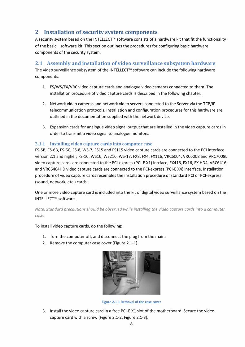
2. Remove the computer case cover (Figure 2.1-1).
Figure 2.1-1 Removal of the case cover
3. Install the video capture card in a free PCI-E X1 slot of the motherboard. Secure the video
capture card with a screw (Figure 2.1-2, Figure 2.1-3).
9
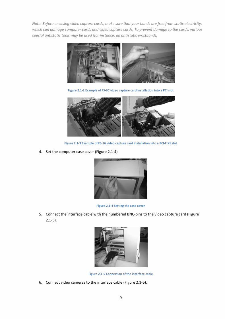
Note. Before encasing video capture cards, make sure that your hands are free from static electricity,
which can damage computer cards and video capture cards. To prevent damage to the cards, various
special antistatic tools may be used (for instance, an antistatic wristband).
Figure 2.1-2 Example of FS-6C video capture card installation into a PCI slot
Figure 2.1-3 Example of FS-16 video capture card installation into a PCI-E X1 slot
4. Set the computer case cover (Figure 2.1-4).
Figure 2.1-4 Setting the case cover
5. Connect the interface cable with the numbered BNC-pins to the video capture card (Figure
2.1-5).
Figure 2.1-5 Connection of the interface cable
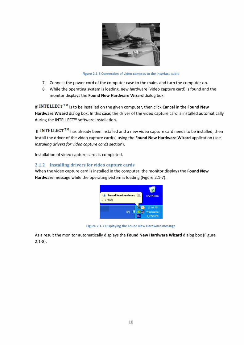
6. Connect video cameras to the interface cable (Figure 2.1-6).
10
Figure 2.1-6 Connection of video cameras to the interface cable
7. Connect the power cord of the computer case to the mains and turn the computer on.
8. While the operating system is loading, new hardware (video capture card) is found and the
monitor displays the Found New Hardware Wizard dialog box.
If is to be installed on the given computer, then click Cancel in the Found New
Hardware Wizard dialog box. In this case, the driver of the video capture card is installed automatically
during the INTELLECT™ software installation.
If has already been installed and a new video capture card needs to be installed, then
install the driver of the video capture card(s) using the Found New Hardware Wizard application (see
Installing drivers for video capture cards section).
Installation of video capture cards is completed.
2.1.2 Installing drivers for video capture cards
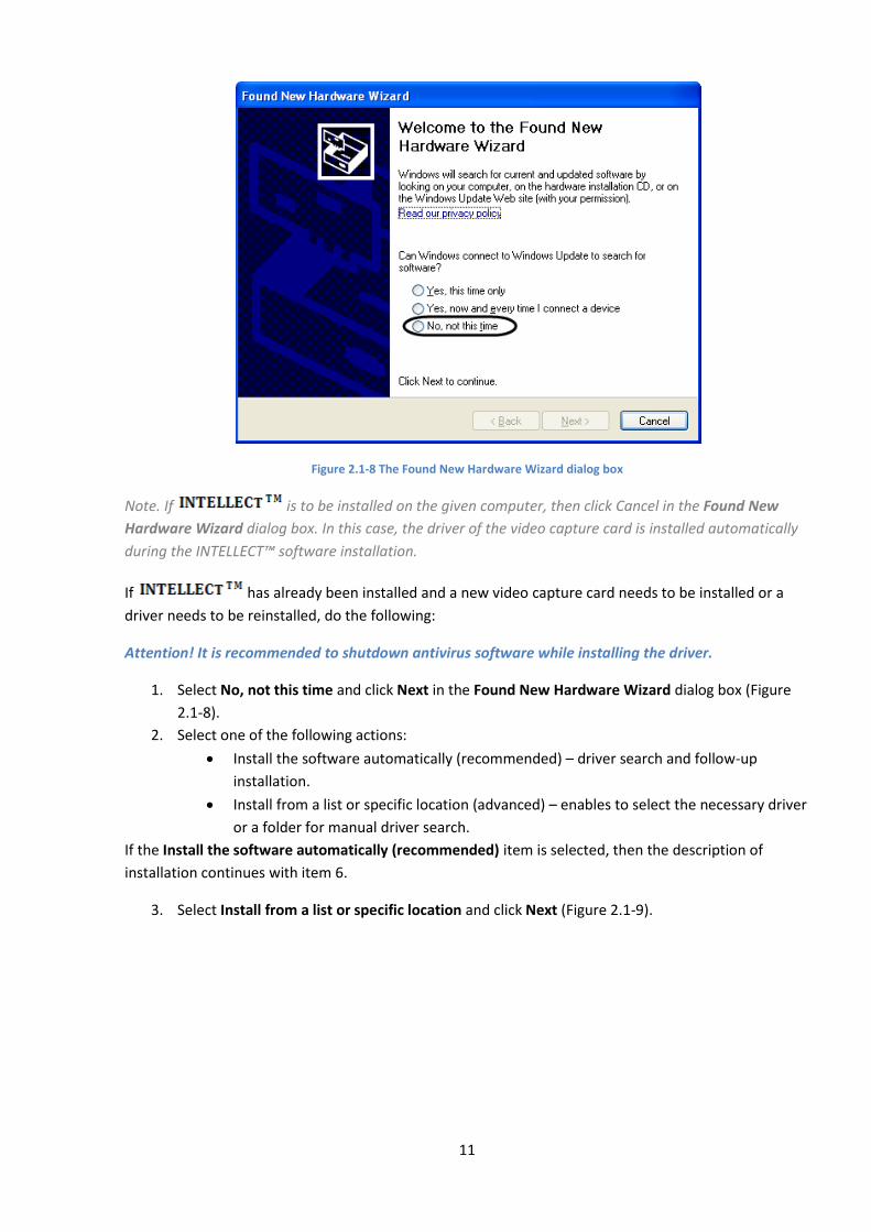
When the video capture card is installed in the computer, the monitor displays the Found New
Hardware message while the operating system is loading (Figure 2.1-7).
Figure 2.1-7 Displaying the Found New Hardware message
As a result the monitor automatically displays the Found New Hardware Wizard dialog box (Figure
2.1-8).
11
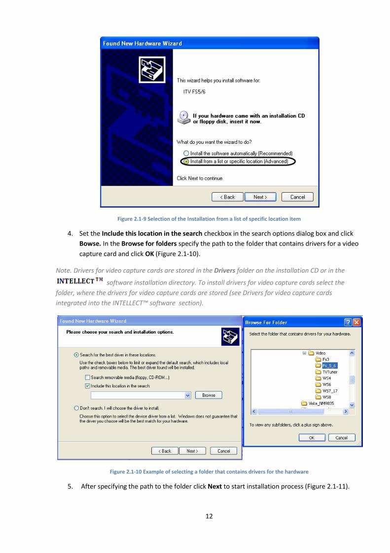
Figure 2.1-8 The Found New Hardware Wizard dialog box
Note. If is to be installed on the given computer, then click Cancel in the Found New
Hardware Wizard dialog box. In this case, the driver of the video capture card is installed automatically
during the INTELLECT™ software installation.
If has already been installed and a new video capture card needs to be installed or a
driver needs to be reinstalled, do the following:
Attention! It is recommended to shutdown antivirus software while installing the driver.
1. Select No, not this time and click Next in the Found New Hardware Wizard dialog box (Figure
2.1-8).
2. Select one of the following actions:
Install the software automatically (recommended) – driver search and follow-up
installation.
Install from a list or specific location (advanced) – enables to select the necessary driver
or a folder for manual driver search.
If the Install the software automatically (recommended) item is selected, then the description of
installation continues with item 6.
3. Select Install from a list or specific location and click Next (Figure 2.1-9).
12
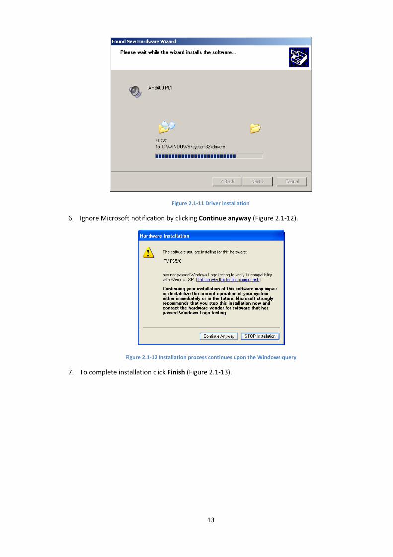
Figure 2.1-9 Selection of the Installation from a list of specific location item
4. Set the Include this location in the search checkbox in the search options dialog box and click
Bowse. In the Browse for folders specify the path to the folder that contains drivers for a video
capture card and click OK (Figure 2.1-10).
Note. Drivers for video capture cards are stored in the Drivers folder on the installation CD or in the
software installation directory. To install drivers for video capture cards select the
folder, where the drivers for video capture cards are stored (see Drivers for video capture cards
integrated into the INTELLECT™ software section).
Figure 2.1-10 Example of selecting a folder that contains drivers for the hardware
5. After specifying the path to the folder click Next to start installation process (Figure 2.1-11).
13
Figure 2.1-11 Driver installation
6. Ignore Microsoft notification by clicking Continue anyway (Figure 2.1-12).
Figure 2.1-12 Installation process continues upon the Windows query
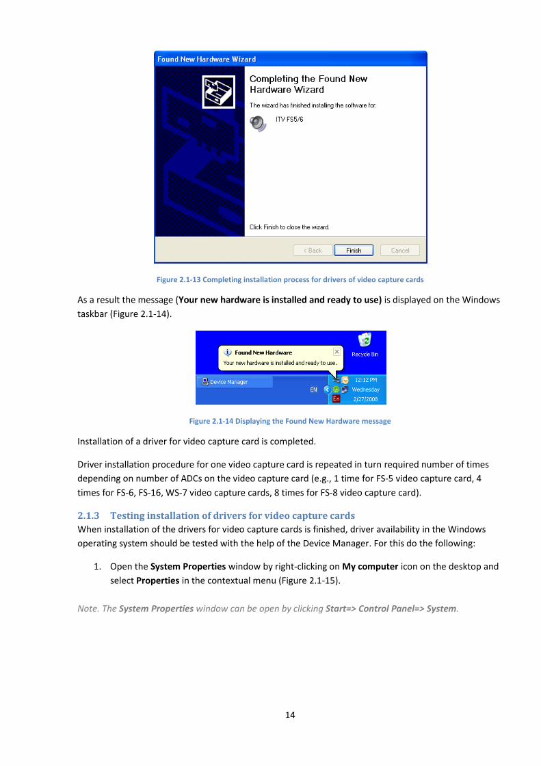
7. To complete installation click Finish (Figure 2.1-13).
14
Figure 2.1-13 Completing installation process for drivers of video capture cards
As a result the message (Your new hardware is installed and ready to use) is displayed on the Windows
taskbar (Figure 2.1-14).
Figure 2.1-14 Displaying the Found New Hardware message
Installation of a driver for video capture card is completed.
Driver installation procedure for one video capture card is repeated in turn required number of times
depending on number of ADCs on the video capture card (e.g., 1 time for FS-5 video capture card, 4
times for FS-6, FS-16, WS-7 video capture cards, 8 times for FS-8 video capture card).
2.1.3 Testing installation of drivers for video capture cards
When installation of the drivers for video capture cards is finished, driver availability in the Windows
operating system should be tested with the help of the Device Manager. For this do the following:
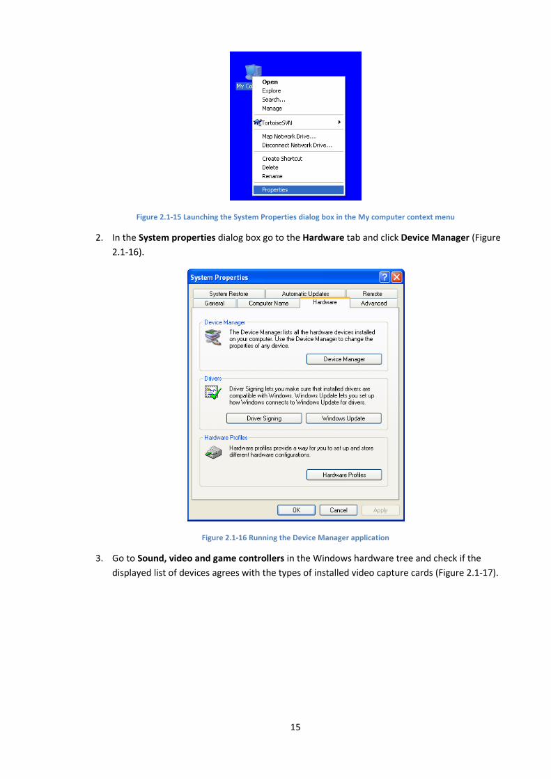
1. Open the System Properties window by right-clicking on My computer icon on the desktop and
select Properties in the contextual menu (Figure 2.1-15).
Note. The System Properties window can be open by clicking Start=> Control Panel=> System.
15
Figure 2.1-15 Launching the System Properties dialog box in the My computer context menu
2. In the System properties dialog box go to the Hardware tab and click Device Manager (Figure
2.1-16).
Figure 2.1-16 Running the Device Manager application
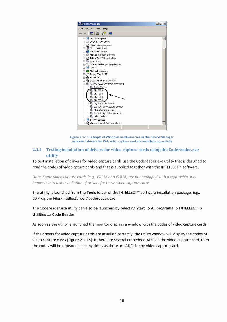
3. Go to Sound, video and game controllers in the Windows hardware tree and check if the
displayed list of devices agrees with the types of installed video capture cards (Figure 2.1-17).
16
Figure 2.1-17 Example of Windows hardware tree in the Device Manager window if drivers for FS-6 video capture card are installed successfully
2.1.4 Testing installation of drivers for video capture cards using the Codereader.exe
utility
To test installation of drivers for video capture cards use the Codereader.exe utility that is designed to
read the codes of video cpture cards and that is supplied together with the INTELLECT™ software.
Note. Some video capture cards (e.g., FX116 and FX416) are not equipped with a cryptochip. It is
impossible to test installation of drivers for these video capture cards.
The utility is launched from the Tools folder of the INTELLECT™ software installation package. E.g.,
C:\Program Files\Intellect\Tools\codereader.exe.
The Codereader.exe utility can also be launched by selecting Start All programs INTELLECT
Utilities Code Reader.
As soon as the utility is launched the monitor displays a window with the codes of video capture cards.
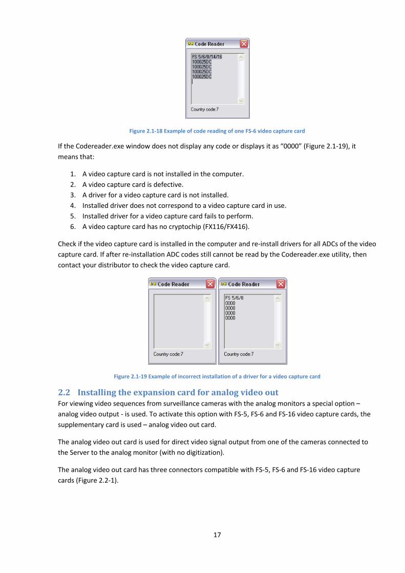
If the drivers for video capture cards are installed correctly, the utility window will display the codes of
video capture cards (Figure 2.1-18). If there are several embedded ADCs in the video capture card, then
the codes will be repeated as many times as there are ADCs in the video capture card.
17
Figure 2.1-18 Example of code reading of one FS-6 video capture card
If the Codereader.exe window does not display any code or displays it as “0000” (Figure 2.1-19), it
means that:
1. A video capture card is not installed in the computer.
2. A video capture card is defective.
3. A driver for a video capture card is not installed.
4. Installed driver does not correspond to a video capture card in use.
5. Installed driver for a video capture card fails to perform.
6. A video capture card has no cryptochip (FX116/FX416).
Check if the video capture card is installed in the computer and re-install drivers for all ADCs of the video
capture card. If after re-installation ADC codes still cannot be read by the Codereader.exe utility, then
contact your distributor to check the video capture card.
Figure 2.1-19 Example of incorrect installation of a driver for a video capture card
2.2 Installing the expansion card for analog video out For viewing video sequences from surveillance cameras with the analog monitors a special option –
analog video output - is used. To activate this option with FS-5, FS-6 and FS-16 video capture cards, the
supplementary card is used – analog video out card.
The analog video out card is used for direct video signal output from one of the cameras connected to
the Server to the analog monitor (with no digitization).
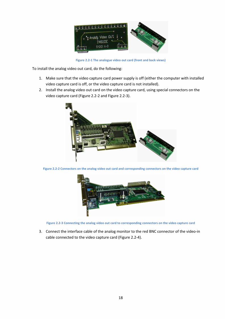
The analog video out card has three connectors compatible with FS-5, FS-6 and FS-16 video capture
cards (Figure 2.2-1).
18
Figure 2.2-1 The analogue video out card (front and back views)
To install the analog video out card, do the following:
1. Make sure that the video capture card power supply is off (either the computer with installed
video capture card is off, or the video capture card is not installed).
2. Install the analog video out card on the video capture card, using special connectors on the
video capture card (Figure 2.2-2 and Figure 2.2-3).
Figure 2.2-2 Connectors on the analog video out card and corresponding connectors on the video capture card
Figure 2.2-3 Connecting the analog video out card to corresponding connectors on the video capture card
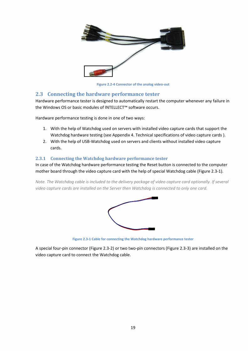
3. Connect the interface cable of the analog monitor to the red BNC connector of the video-in
cable connected to the video capture card (Figure 2.2-4).
19
Figure 2.2-4 Connector of the analog video-out
2.3 Connecting the hardware performance tester Hardware performance tester is designed to automatically restart the computer whenever any failure in
the Windows OS or basic modules of INTELLECT™ software occurs.
Hardware performance testing is done in one of two ways:
1. With the help of Watchdog used on servers with installed video capture cards that support the
Watchdog hardware testing (see Appendix 4. Technical specifications of video capture cards ).
2. With the help of USB-Watchdog used on servers and clients without installed video capture
cards.
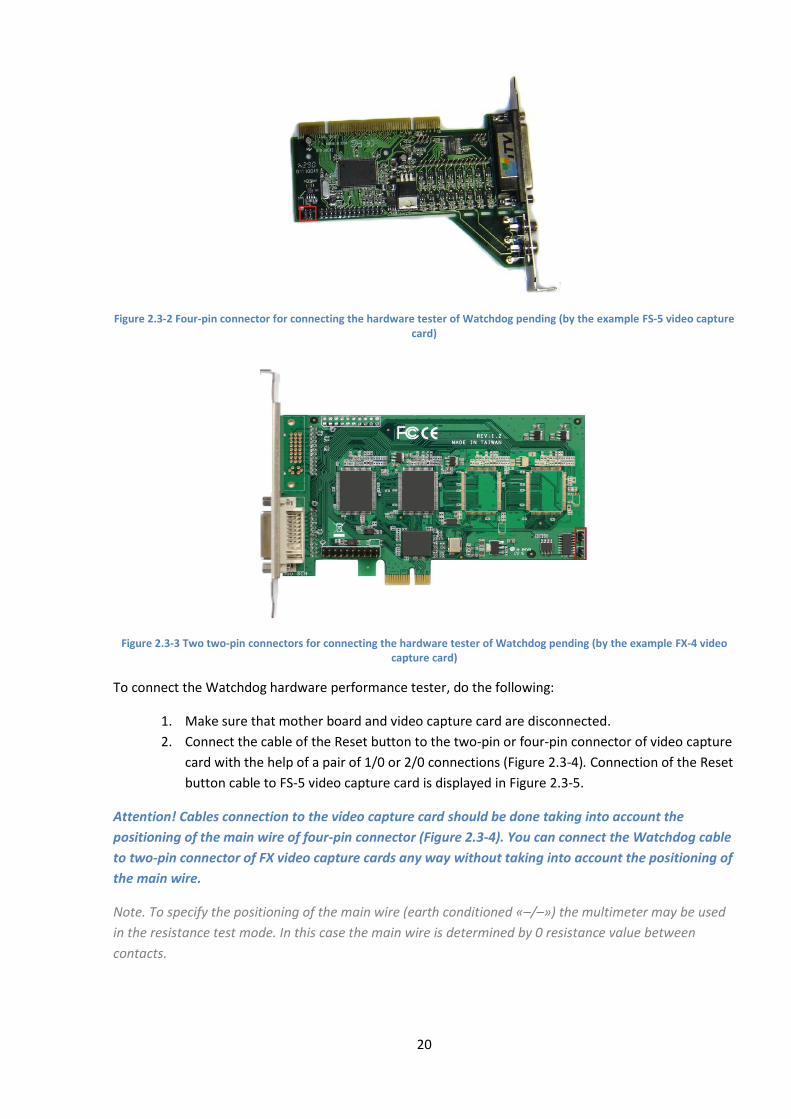
2.3.1 Connecting the Watchdog hardware performance tester
In case of the Watchdog hardware performance testing the Reset button is connected to the computer
mother board through the video capture card with the help of special Watchdog cable (Figure 2.3-1).
Note. The Watchdog cable is included to the delivery package of video capture card optionally. If several
video capture cards are installed on the Server then Watchdog is connected to only one card.
Figure 2.3-1 Cable for connecting the Watchdog hardware performance tester
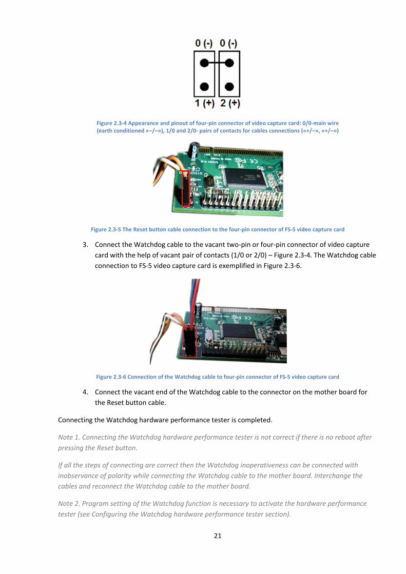
A special four-pin connector (Figure 2.3-2) or two two-pin connectors (Figure 2.3-3) are installed on the
video capture card to connect the Watchdog cable.
20
Figure 2.3-2 Four-pin connector for connecting the hardware tester of Watchdog pending (by the example FS-5 video capture card)
Figure 2.3-3 Two two-pin connectors for connecting the hardware tester of Watchdog pending (by the example FX-4 video capture card)
To connect the Watchdog hardware performance tester, do the following:
1. Make sure that mother board and video capture card are disconnected.
2. Connect the cable of the Reset button to the two-pin or four-pin connector of video capture
card with the help of a pair of 1/0 or 2/0 connections (Figure 2.3-4). Connection of the Reset
button cable to FS-5 video capture card is displayed in Figure 2.3-5.
Attention! Cables connection to the video capture card should be done taking into account the
positioning of the main wire of four-pin connector (Figure 2.3-4). You can connect the Watchdog cable
to two-pin connector of FX video capture cards any way without taking into account the positioning of
the main wire.
Note. To specify the positioning of the main wire (earth conditioned «–/–») the multimeter may be used
in the resistance test mode. In this case the main wire is determined by 0 resistance value between
contacts.
21
Figure 2.3-4 Appearance and pinout of four-pin connector of video capture card: 0/0-main wire (earth conditioned «–/–»), 1/0 and 2/0- pairs of contacts for cables connections («+/–», «+/–»)
Figure 2.3-5 The Reset button cable connection to the four-pin connector of FS-5 video capture card
3. Connect the Watchdog cable to the vacant two-pin or four-pin connector of video capture
card with the help of vacant pair of contacts (1/0 or 2/0) – Figure 2.3-4. The Watchdog cable
connection to FS-5 video capture card is exemplified in Figure 2.3-6.
Figure 2.3-6 Connection of the Watchdog cable to four-pin connector of FS-5 video capture card
4. Connect the vacant end of the Watchdog cable to the connector on the mother board for
the Reset button cable.
Connecting the Watchdog hardware performance tester is completed.
Note 1. Connecting the Watchdog hardware performance tester is not correct if there is no reboot after
pressing the Reset button.
If all the steps of connecting are correct then the Watchdog inoperativeness can be connected with
inobservance of polarity while connecting the Watchdog cable to the mother board. Interchange the
cables and reconnect the Watchdog cable to the mother board.
Note 2. Program setting of the Watchdog function is necessary to activate the hardware performance
tester (see Configuring the Watchdog hardware performance tester section).
22
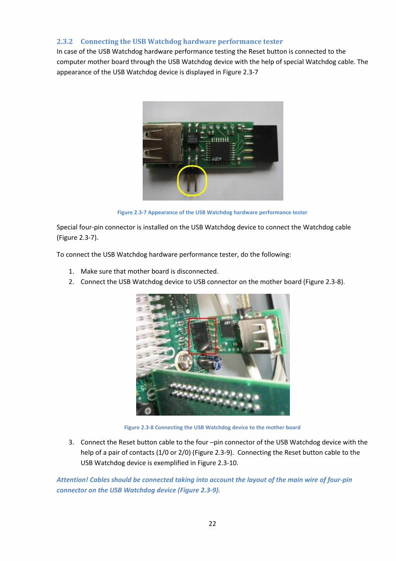
2.3.2 Connecting the USB Watchdog hardware performance tester
In case of the USB Watchdog hardware performance testing the Reset button is connected to the
computer mother board through the USB Watchdog device with the help of special Watchdog cable. The
appearance of the USB Watchdog device is displayed in Figure 2.3-7
Figure 2.3-7 Appearance of the USB Watchdog hardware performance tester
Special four-pin connector is installed on the USB Watchdog device to connect the Watchdog cable
(Figure 2.3-7).
To connect the USB Watchdog hardware performance tester, do the following:
1. Make sure that mother board is disconnected.
2. Connect the USB Watchdog device to USB connector on the mother board (Figure 2.3-8).
Figure 2.3-8 Connecting the USB Watchdog device to the mother board
3. Connect the Reset button cable to the four –pin connector of the USB Watchdog device with the
help of a pair of contacts (1/0 or 2/0) (Figure 2.3-9). Connecting the Reset button cable to the
USB Watchdog device is exemplified in Figure 2.3-10.
Attention! Cables should be connected taking into account the layout of the main wire of four-pin
connector on the USB Watchdog device (Figure 2.3-9).
23
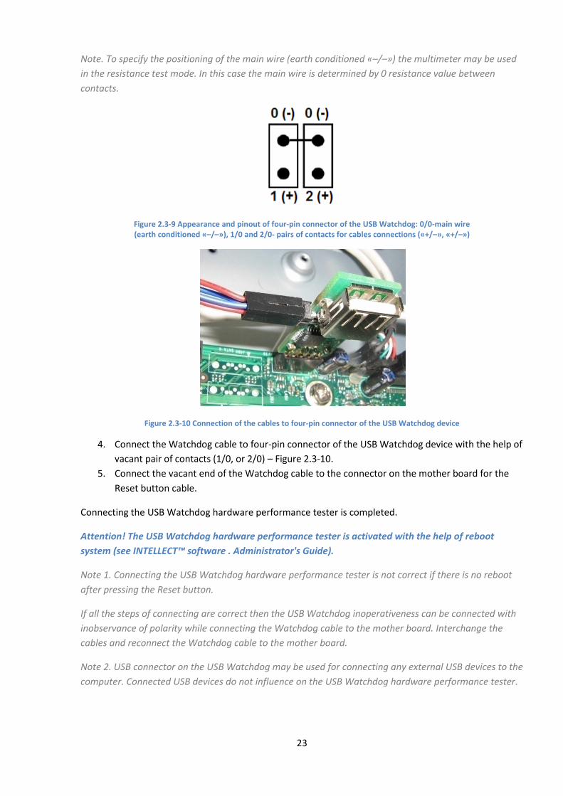
Note. To specify the positioning of the main wire (earth conditioned «–/–») the multimeter may be used
in the resistance test mode. In this case the main wire is determined by 0 resistance value between
contacts.
Figure 2.3-9 Appearance and pinout of four-pin connector of the USB Watchdog: 0/0-main wire (earth conditioned «–/–»), 1/0 and 2/0- pairs of contacts for cables connections («+/–», «+/–»)
Figure 2.3-10 Connection of the cables to four-pin connector of the USB Watchdog device
4. Connect the Watchdog cable to four-pin connector of the USB Watchdog device with the help of
vacant pair of contacts (1/0, or 2/0) – Figure 2.3-10.
5. Connect the vacant end of the Watchdog cable to the connector on the mother board for the
Reset button cable.
Connecting the USB Watchdog hardware performance tester is completed.
Attention! The USB Watchdog hardware performance tester is activated with the help of reboot
system (see INTELLECT™ software . Administrator's Guide).
Note 1. Connecting the USB Watchdog hardware performance tester is not correct if there is no reboot
after pressing the Reset button.
If all the steps of connecting are correct then the USB Watchdog inoperativeness can be connected with
inobservance of polarity while connecting the Watchdog cable to the mother board. Interchange the
cables and reconnect the Watchdog cable to the mother board.
Note 2. USB connector on the USB Watchdog may be used for connecting any external USB devices to the
computer. Connected USB devices do not influence on the USB Watchdog hardware performance tester.

24
2.4 Connecting DI/DO cards DI/DO card is connected to the video capture card and is used for connecting guard loops (DI) and DO to
the control system - the server with installed INTELLECT™ software. General information about DI and
DO is given in Table 2.4-1:
Table 2.4-1 General information on DI/DO
Type of device
Description Functions Operation conditions
Changes in operation condition
Examples of devices
DI (digital in) Interface line of external sensor and control system
Informs the control system about changes in sensor status
Closed– logical one Open – logical zero
Opening/closing – when sensor detects the alarm
Annunciators (smoke, heat, window, etc), button
DO (digital out)
Interface line of control system and executive device
Changes operation condition of executive device on command from the control system
Closed – logical one Open – logical zero
Opening/closing – on command from the control system.
Annunciators (light, sound, etc.), mechanized gates
Electrical and technical specifications of DI/DO cards are given in Appendix 6. Electrical and technical
specifications of DI/DO cards section.
2.4.1 Connecting 4/4 and 16/4 DI/DO cards
Multichannel digital-analogue converting 4/4 and 16/4 DI/DO cards may be installed on the server
depending on security system requirements (Figure 2.4-1).
Figure 2.4-1 The 4/4 and 16/4 DI/DO cards
The 4/4 DI/DO cards enable to process the signals from 4 digital in, and the 16/4 cards - from 16 digital
in. Simultaneously with the DI signals processing, these cards perform digital-analogue converting and
delivering up to 4 control signals to executive devices (DO).
The 4/4 and 16/4 DI/DO cards have power (24V) and grounding leads and are installed on the FS-5, FS-6,
FS-16, FS-8 video capture cards.
To connect DI/DO cards, do the following:
1. Make sure that power supply of the video capture card is off.
2. Install the DI/DO card on the video capture card with the help of special connectors. (Figure
2.4-2, Figure 2.4-3, Figure 2.4-4).

25
Figure 2.4-2 Connector on the DI/DO card for connecting to the video capture card (is exemplified in 4/4 and 16/4 DI/DO cards)
Figure 2.4-3 Connector on the video capture card for connecting the DI/DO card (is exemplified in FS6 video capture card)
Figure 2.4-4 Installation of the DI/DO card on the video capture card (is exemplified in 4/4 and 16/4 DI/DO cards and FS6 video capture card)
3. Fix the DI/DO card on the video capture card with the help of screws included in the distribution
kit of the DI/DO card.
4. Connect the interface cable included in the distribution kit of the DI/DO card, to the DI/DO card
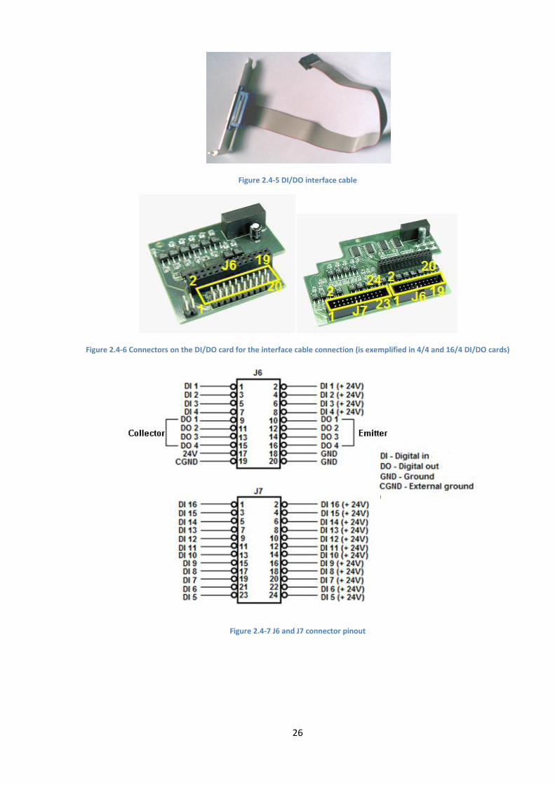
with the help of special connector (Figure 2.4-5, Figure 2.4-6, Figure 2.4-7, Figure 2.4-8)
Note. For interface cable connection the 4/4 DI/DO card has J6 connector, 16/4 DI/DO card has J6 and J7
connectors (Figure 2.4-6, Figure 2.4-7).
Attention! The first wire of the interface cable (marked red) should match the first pin of
corresponding connector of the DI/DO card (Figure 2.4-6, Figure 2.4-7, Figure 2.4-8).
26
Figure 2.4-5 DI/DO interface cable
Figure 2.4-6 Connectors on the DI/DO card for the interface cable connection (is exemplified in 4/4 and 16/4 DI/DO cards)
Figure 2.4-7 J6 and J7 connector pinout
27
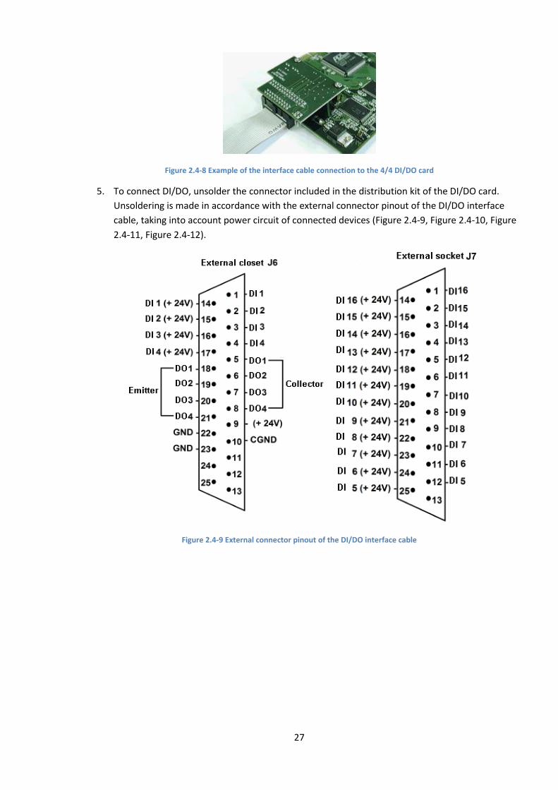
Figure 2.4-8 Example of the interface cable connection to the 4/4 DI/DO card
5. To connect DI/DO, unsolder the connector included in the distribution kit of the DI/DO card.
Unsoldering is made in accordance with the external connector pinout of the DI/DO interface
cable, taking into account power circuit of connected devices (Figure 2.4-9, Figure 2.4-10, Figure
2.4-11, Figure 2.4-12).
Figure 2.4-9 External connector pinout of the DI/DO interface cable
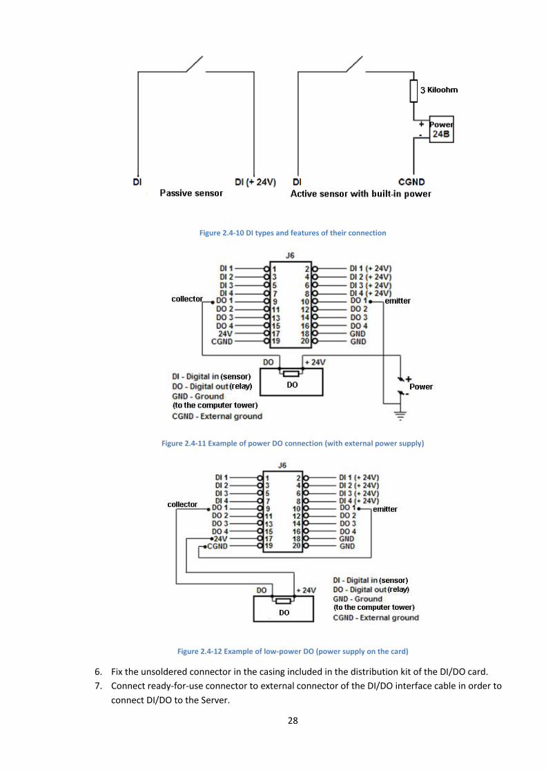
28
Figure 2.4-10 DI types and features of their connection
Figure 2.4-11 Example of power DO connection (with external power supply)
Figure 2.4-12 Example of low-power DO (power supply on the card)
6. Fix the unsoldered connector in the casing included in the distribution kit of the DI/DO card.
7. Connect ready-for-use connector to external connector of the DI/DO interface cable in order to
connect DI/DO to the Server.

29
The DI/DO cards connection is completed.
2.4.2 Connecting 4/4 DI/DO (low profile) cards
Building security video subsystem with the use of FS115/FX4/FX8/FX16 video capture cards one can
install 4/4 DI/DO cards (low profile) in order to connect external sensors (DI) and executive devices (DO)
to the Server.
To connect the 4/4 DI/DO (low profile) card, do the following:
1. Make sure that the computer is turned off.
2. Connect the 4/4 DI/DO (low profile) card to the video capture card with the help of loop
included in the distribution kit. The loop is connected to J2 and J3 connectors (Figure 2.4-13 and
Appendix 5. Video capture cards pins section).
Figure 2.4-13 Diagram of the 4/4 DI/DO (low profile) card connection to FS115 card
3. Connect the cable of computer PSU (disk drive power supply) to J4 connector (Figure 2.4-13) of
the 4/4 DI/DO (low profile) card.
4. Install the card into vacant computer slot and fix it in the casing with the help of screw.
5. To connect DI/DO, unsolder the connector. Unsoldering is made in accordance with the external
connector pinout of the 4/4 DI/DO (low profile) card (Figure 2.4-14).
30
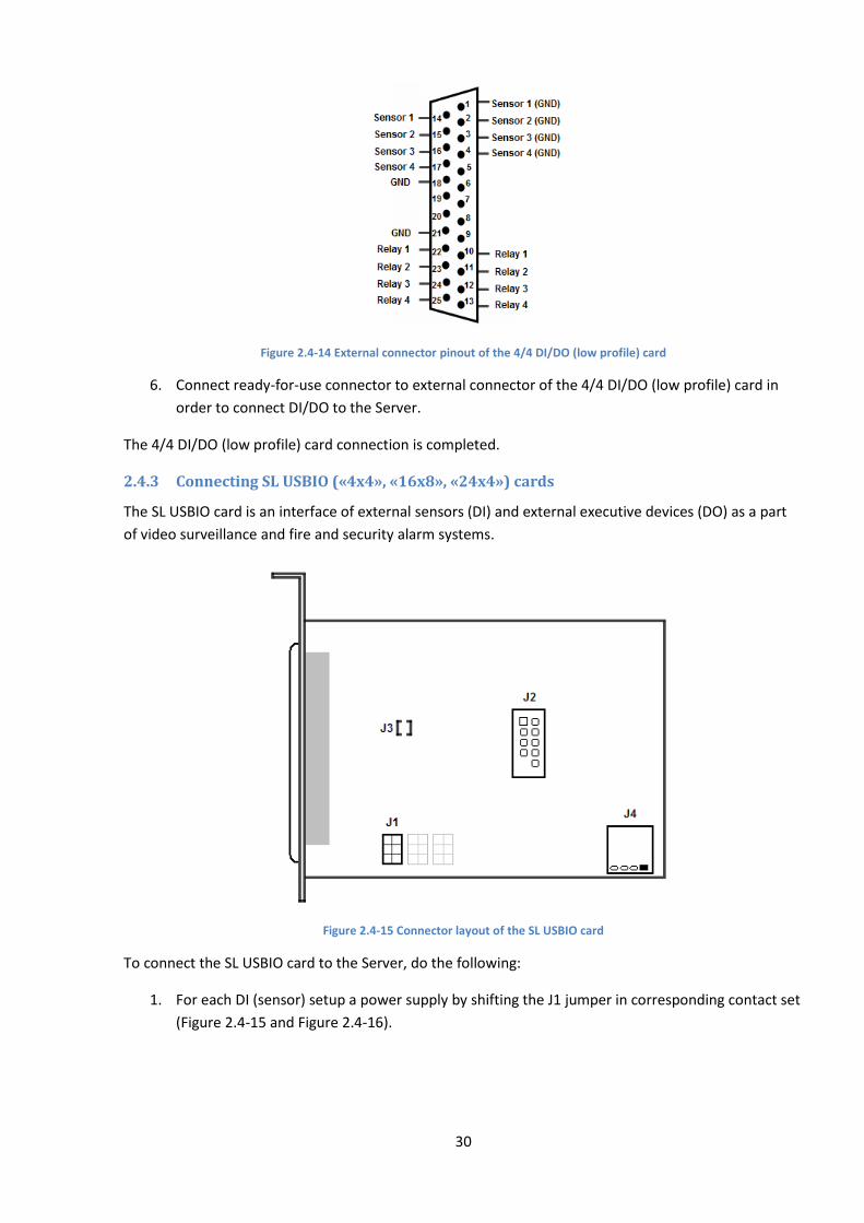
Figure 2.4-14 External connector pinout of the 4/4 DI/DO (low profile) card
6. Connect ready-for-use connector to external connector of the 4/4 DI/DO (low profile) card in
order to connect DI/DO to the Server.
The 4/4 DI/DO (low profile) card connection is completed.
2.4.3 Connecting SL USBIO («4x4», «16x8», «24x4») cards
The SL USBIO card is an interface of external sensors (DI) and external executive devices (DO) as a part
of video surveillance and fire and security alarm systems.
Figure 2.4-15 Connector layout of the SL USBIO card
To connect the SL USBIO card to the Server, do the following:
1. For each DI (sensor) setup a power supply by shifting the J1 jumper in corresponding contact set
(Figure 2.4-15 and Figure 2.4-16).
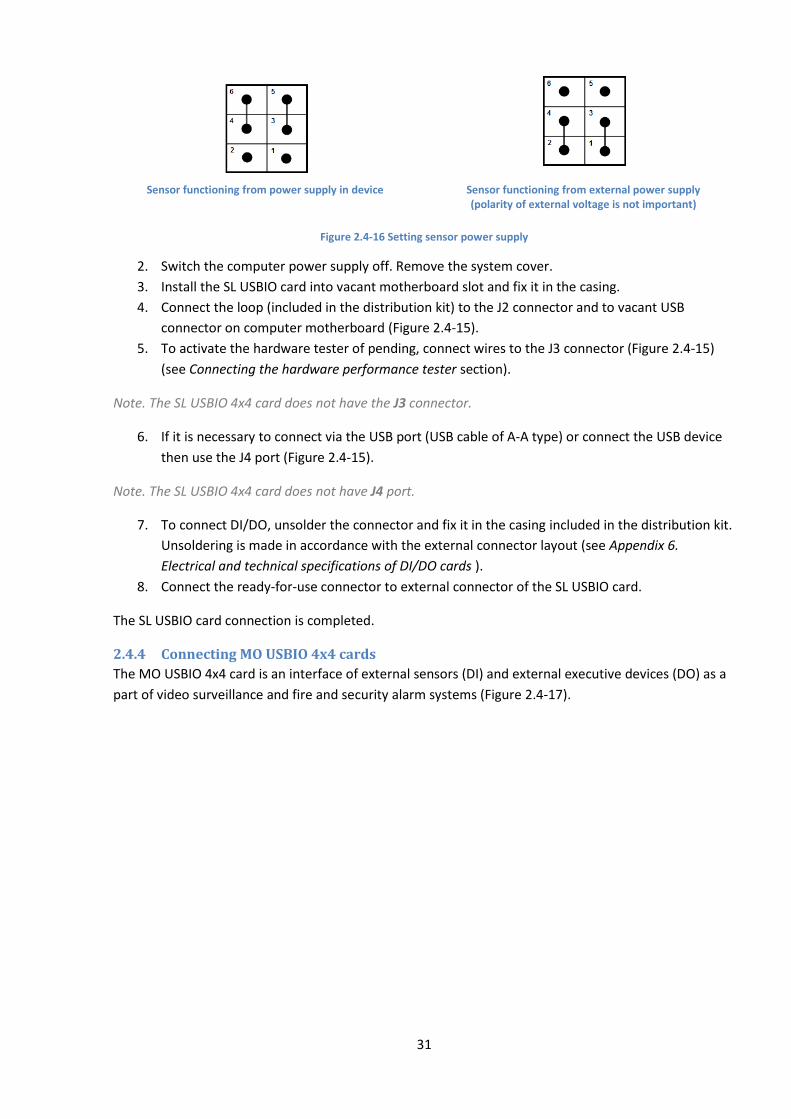
31
Sensor functioning from power supply in device
Sensor functioning from external power supply (polarity of external voltage is not important)
Figure 2.4-16 Setting sensor power supply
2. Switch the computer power supply off. Remove the system cover.
3. Install the SL USBIO card into vacant motherboard slot and fix it in the casing.
4. Connect the loop (included in the distribution kit) to the J2 connector and to vacant USB
connector on computer motherboard (Figure 2.4-15).
5. To activate the hardware tester of pending, connect wires to the J3 connector (Figure 2.4-15)
(see Connecting the hardware performance tester section).
Note. The SL USBIO 4x4 card does not have the J3 connector.
6. If it is necessary to connect via the USB port (USB cable of A-A type) or connect the USB device
then use the J4 port (Figure 2.4-15).
Note. The SL USBIO 4x4 card does not have J4 port.
7. To connect DI/DO, unsolder the connector and fix it in the casing included in the distribution kit.
Unsoldering is made in accordance with the external connector layout (see Appendix 6.
Electrical and technical specifications of DI/DO cards ).
8. Connect the ready-for-use connector to external connector of the SL USBIO card.
The SL USBIO card connection is completed.
2.4.4 Connecting MO USBIO 4x4 cards
The MO USBIO 4х4 card is an interface of external sensors (DI) and external executive devices (DO) as a
part of video surveillance and fire and security alarm systems (Figure 2.4-17).
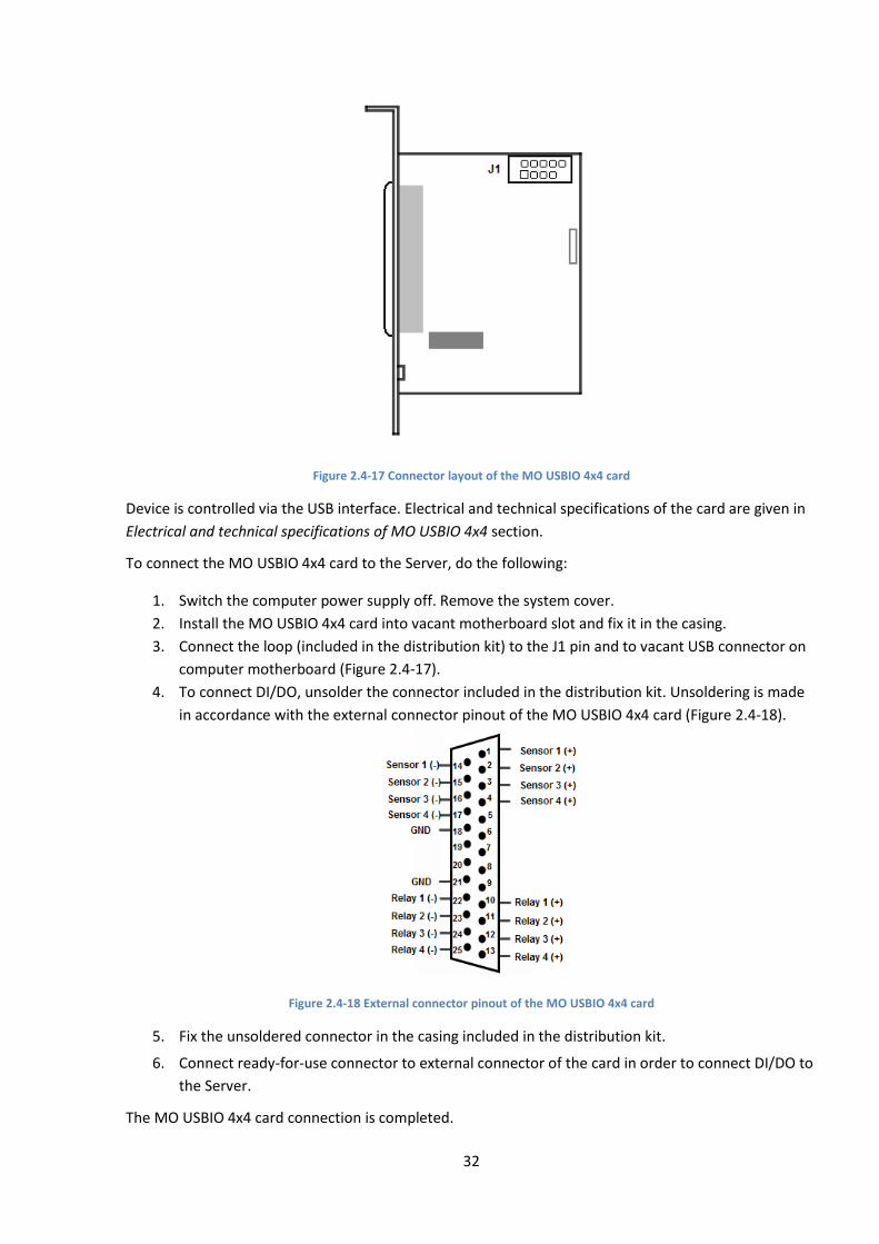
32
Figure 2.4-17 Connector layout of the MO USBIO 4х4 card
Device is controlled via the USB interface. Electrical and technical specifications of the card are given in
Electrical and technical specifications of MO USBIO 4x4 section.
To connect the MO USBIO 4х4 card to the Server, do the following:
1. Switch the computer power supply off. Remove the system cover.
2. Install the MO USBIO 4х4 card into vacant motherboard slot and fix it in the casing.
3. Connect the loop (included in the distribution kit) to the J1 pin and to vacant USB connector on
computer motherboard (Figure 2.4-17).
4. To connect DI/DO, unsolder the connector included in the distribution kit. Unsoldering is made
in accordance with the external connector pinout of the MO USBIO 4х4 card (Figure 2.4-18).
Figure 2.4-18 External connector pinout of the MO USBIO 4х4 card
5. Fix the unsoldered connector in the casing included in the distribution kit.
6. Connect ready-for-use connector to external connector of the card in order to connect DI/DO to
the Server.
The MO USBIO 4x4 card connection is completed.
33
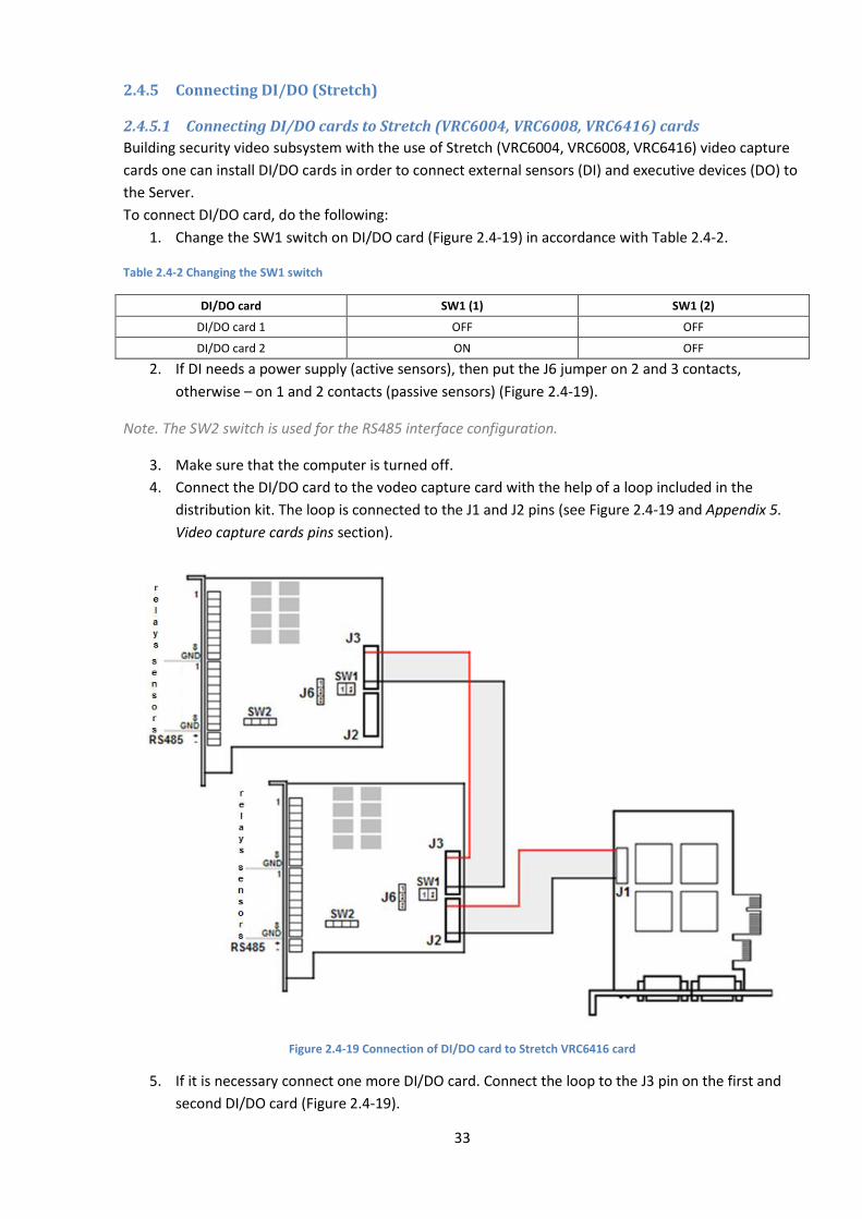
2.4.5 Connecting DI/DO (Stretch)
2.4.5.1 Connecting DI/DO cards to Stretch (VRC6004, VRC6008, VRC6416) cards
Building security video subsystem with the use of Stretch (VRC6004, VRC6008, VRC6416) video capture
cards one can install DI/DO cards in order to connect external sensors (DI) and executive devices (DO) to
the Server.
To connect DI/DO card, do the following:
1. Change the SW1 switch on DI/DO card (Figure 2.4-19) in accordance with Table 2.4-2.
Table 2.4-2 Changing the SW1 switch
DI/DO card SW1 (1) SW1 (2)
DI/DO card 1 OFF OFF
DI/DO card 2 ON OFF
2. If DI needs a power supply (active sensors), then put the J6 jumper on 2 and 3 contacts,
otherwise – on 1 and 2 contacts (passive sensors) (Figure 2.4-19).
Note. The SW2 switch is used for the RS485 interface configuration.
3. Make sure that the computer is turned off.
4. Connect the DI/DO card to the vodeo capture card with the help of a loop included in the
distribution kit. The loop is connected to the J1 and J2 pins (see Figure 2.4-19 and Appendix 5.
Video capture cards pins section).
Figure 2.4-19 Connection of DI/DO card to Stretch VRC6416 card
5. If it is necessary connect one more DI/DO card. Connect the loop to the J3 pin on the first and
second DI/DO card (Figure 2.4-19).
34
6. Install the DI/DO card into vacant motherboard slot and fix it in the casing.
7. Connect DI and DO in accordance with the pinout of external pin of the DI/DO card (Figure
2.4-19).
Connection of the DI/DO card is completed.
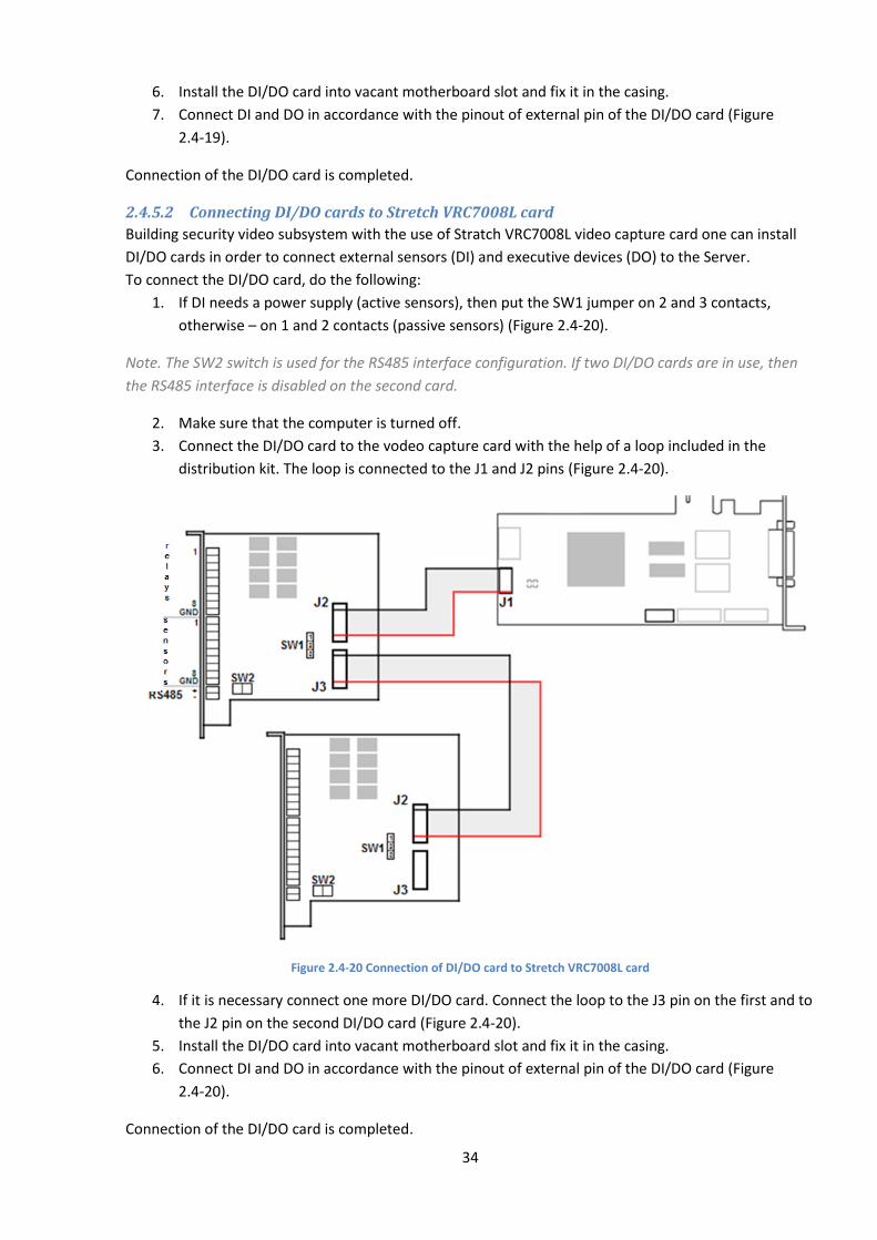
2.4.5.2 Connecting DI/DO cards to Stretch VRC7008L card
Building security video subsystem with the use of Stratch VRC7008L video capture card one can install
DI/DO cards in order to connect external sensors (DI) and executive devices (DO) to the Server.
To connect the DI/DO card, do the following:
1. If DI needs a power supply (active sensors), then put the SW1 jumper on 2 and 3 contacts,
otherwise – on 1 and 2 contacts (passive sensors) (Figure 2.4-20).
Note. The SW2 switch is used for the RS485 interface configuration. If two DI/DO cards are in use, then
the RS485 interface is disabled on the second card.
2. Make sure that the computer is turned off.
3. Connect the DI/DO card to the vodeo capture card with the help of a loop included in the
distribution kit. The loop is connected to the J1 and J2 pins (Figure 2.4-20).
Figure 2.4-20 Connection of DI/DO card to Stretch VRC7008L card
4. If it is necessary connect one more DI/DO card. Connect the loop to the J3 pin on the first and to
the J2 pin on the second DI/DO card (Figure 2.4-20).
5. Install the DI/DO card into vacant motherboard slot and fix it in the casing.
6. Connect DI and DO in accordance with the pinout of external pin of the DI/DO card (Figure
2.4-20).
Connection of the DI/DO card is completed.

35
2.5 Connecting MO USBIO 4х4 external module The MO USBIO 4х4 module is an interface for external sensors (DI) and external executive devices (DO)
as a part of video surveillance and fire and security alarm systems (Figure 2.5-1).
Figure 2.5-1 Модуль «MO USBIO 4х4»
External module is controlled via the USB interface. Electrical and technical specifications of the module
are given in Electrical and technical specifications of MO USBIO 4x4 section.
To configure the MO USBIO 4х4 external module, do the following:
1. Connect the MO USBIO 4х4 module to the server via the USB cable included in the distribution
kit.
2. To connect DI/DO, unsolder the connector included in the distribution kit. Unsoldering is made
in accordance with the external connector pinout of the MO USBIO 4х4 module. В зависимости
от модификации модуля может использоваться один из вариантов разводки внешнего
разъема, приведенных на Figure 2.5-2.
Figure 2.5-2 Варианты разводки внешнего разъема модуля «MO USBIO 4х4»
3. Fix the unsoldered connector in the casing included in the distribution kit.
4. Connect ready-for-use connector to external connector of the card in order to connect DI/DO to
the Server.
The MO USBIO 4x4 external module configuration is completed.
2.6 Assembly and installation of audio subsystem hardware components INTELLECT™ software supports synchro video and audio recording and remote audio monitoring.
36
To enable operation of the audio subsystem, the Operator Workstation should be equipped with
auxiliary hardware, such as sound cards, microphones, loud speakers and earphones.
2.6.1 Supported sound cards and other audio input devices
The following audio input devices can be used in the audio subsystem:
1. Standard sound cards installed in a computer or motherboards integrated in a computer.
2. Multi-channel sound cards such as Comart Hera, MidiMan Delta and Olkha 9Р.
3. Ekholot USB-32, an external module for multi-channel audio signal input (32 channels).
4. Audio input channels of the network devices.
5. Audio input channels of FS/WS cards. As these cards do not have audio output channels for
playing back the audio signal, a sound card is to be installed.
2.6.2 Options for increasing the number of audio input channels when standard sound
cards are used
INTELLECT™-based server can process as many analog audio signals as specified in the key file.
As a rule a standard sound card has only one stereo audio input channel. To increase the number of
audio input channels, the following options are offered:
1. Use a stereo audio input channel of a standard sound card as two separate mono-channels.
2. Use audio input channels of video capture cards.
3. Install several standard sound cards on the server.
Note. Several sound cards of the same type installed within the system may cause conflicts in Windows
OS.
4. Use multi-channel audio input cards (special sound cards support up to 16 separate audio input
channels).
5. Use Ekholot USB-32, an external module for multi-channel audio signal input (32 channels).
2.6.3 Installing audio input devices
Manuals for installing sound cards of other manufacturers and the drivers for these cards, as well as any
other devices are given in the documentation supplied with the hardware.
Sound channels of the network devices do not require any additional installation. The only requirement
is that the device supports communication with the Server via the TCP/IP protocol.
2.6.4 Installing microphones and loud speakers
Microphones are to be installed in inaccessible places, ensuring unobstructed receipt of audio signals.
Each microphone is connected to a sound card installed in a computer or to an audio plug on a
videocapture card.
Loud speakers or earphones designed for audio signal receipt are installed in the Operator Workstation.
Loud speakers or earphones are connected to the audio output plug of the sound card.

37
The layouts of pins for connecting microphones and earphones or loud speakers are given in the
documentation for the sound cards.
Pins supplied with a video capture card are used to connect microphones to these video capture cards.
2.7 Connecting PTZ units and control panels Attention! Before one starts working with a control panel or a PTZ unit it is necessary to read the list
of integrated devices and protocols at AxxonSoft's official website. If the connected device is not in the
list, then its operation is not guaranteed.
The PTZ unit and control panel are connected to the server via a free serial port (COM) (RS-232
interface) (Figure 2.7-1).
Figure 2.7-1 Connecting PTZ units and control panels
As a rule, PTZ units use RS-422 or RS-485 interfaces. The PTZ unit is connected to a COM port of a server
with RS-232 interface via RS-422 converter (RS-485) RS-232.
The PTZ unit uses RS-422/RS-485 based on a 4-wires diagram (2 wires for receipt and 2 wires for
transmission). To control PTZ units from INTELLECT™, only 2 wires are used (transmitting data from the
Server to the PTZ). The “Т+” and “Т-” contacts of the converter are connected to the “R+” and “R-”
contacts of the PTZ.
The control panel is connected via converter RS-422 (RS-485) RS-232. Only two wires, connected to
the Server, are used to control PTZ units via control panel from INTELLECT™.
The PTZ unit and control panel controlling this PTZ unit are to be connected to one Server.
Detailed information about connecting PTZ units and control panels is given in the documentation
accompanying the corresponding devices and converters. An example of controlling PTZ units with the
help of control panel is described in the Telemetry configuration section.
2.8 Connecting and configuring network devices Network devices allow remote video surveillance and audio monitoring using the TCP/IP
telecommunication environment.
Network devices can be defined as separate hardware and software units integrated in the digital video
surveillance system using the TCP/IP telecommunication environment. To work with network devices,
the system requires connection to the telecommunication network using TCP/IP to interact with other
components of the digital video surveillance system.
Network devices for video surveillance and audio monitoring are:
1. network cameras (IP-cameras);
2. various types of network videoservers.

38
Network cameras are designed for video surveillance and transmission of the digital video signal to the
users via the TCP/IP telecommunication environment.
Note. Ifa network camera is equipped with an analog camera instead of a digital one, then a video signal
is first digitized by an AD converter embedded in the camera and then transmitted to the users via the
TCP/IP telecommunication environment.
Network videoservers are connected directly to the analog cameras; they digitize analog video signal
and transmit it to the users via the TCP/IP telecommunication environment. The users operating analog
cameras connected to the network servers can use the same functionality range for the video stream
playback and transmission, as the functionality of network cameras.
Network devices are connected via a standard network pin RJ-45.
Detailed information on connecting network devices to Server is given in the documentation for
corresponding network devices.
39
3 Configuring security system components in INTELLECT™ software
3.1 Configuring video capture cards in INTELLECT™ software
3.1.1 Video subsystem configuration
To set up a video subsystem in the INTELLECT™ software create the Video capture card objects under
which the Camera objects are created.
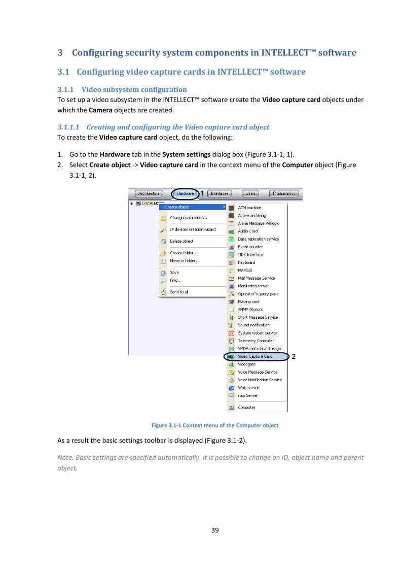
3.1.1.1 Creating and configuring the Video capture card object
To create the Video capture card object, do the following:
1. Go to the Hardware tab in the System settings dialog box (Figure 3.1-1, 1).
2. Select Create object -> Video capture card in the context menu of the Computer object (Figure
3.1-1, 2).
Figure 3.1-1 Context menu of the Computer object
As a result the basic settings toolbar is displayed (Figure 3.1-2).
Note. Basic settings are specified automatically. It is possible to change an ID, object name and parent
object.

40
Figure 3.1-2 Basic settings of the object
3. To create the object, click Apply.
4. Select the created object in the object tree (Figure 3.1-3, 1).
Figure 3.1-3 Configuring the Video capture card object
5. Configure the created object.
5.1. From the Type list select type of the video capture card installed on the Server (Figure 3.1-3, 2).
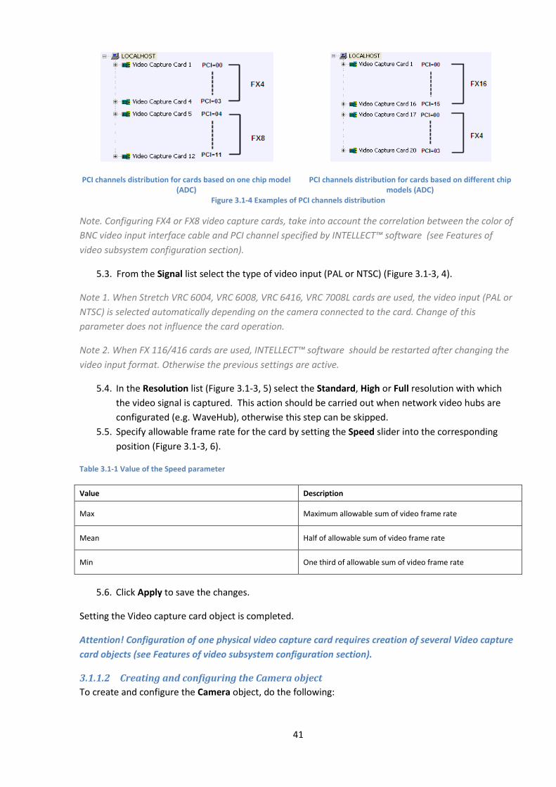
5.2. Specify the PCI channel by selecting value from the PCI channel list (Figure 3.1-3, 3). For cards
based on one chip model (ADC) and one driver (see Drivers for video capture cards integrated
into the INTELLECT™ software section) there is end-to-end distribution of PCI channels that
starts with ‘00’ (Figure 3.1-4).
41
PCI channels distribution for cards based on one chip model (ADC)
PCI channels distribution for cards based on different chip models (ADC)
Figure 3.1-4 Examples of PCI channels distribution
Note. Configuring FX4 or FX8 video capture cards, take into account the correlation between the color of
BNC video input interface cable and PCI channel specified by INTELLECT™ software (see Features of
video subsystem configuration section).
5.3. From the Signal list select the type of video input (PAL or NTSC) (Figure 3.1-3, 4).
Note 1. When Stretch VRC 6004, VRC 6008, VRC 6416, VRC 7008L cards are used, the video input (PAL or
NTSC) is selected automatically depending on the camera connected to the card. Change of this
parameter does not influence the card operation.
Note 2. When FX 116/416 cards are used, INTELLECT™ software should be restarted after changing the
video input format. Otherwise the previous settings are active.
5.4. In the Resolution list (Figure 3.1-3, 5) select the Standard, High or Full resolution with which
the video signal is captured. This action should be carried out when network video hubs are
configurated (e.g. WaveHub), otherwise this step can be skipped.
5.5. Specify allowable frame rate for the card by setting the Speed slider into the corresponding
position (Figure 3.1-3, 6).
Table 3.1-1 Value of the Speed parameter
Value Description
Max Maximum allowable sum of video frame rate
Mean Half of allowable sum of video frame rate
Min One third of allowable sum of video frame rate
5.6. Click Apply to save the changes.
Setting the Video capture card object is completed.
Attention! Configuration of one physical video capture card requires creation of several Video capture
card objects (see Features of video subsystem configuration section).
3.1.1.2 Creating and configuring the Camera object
To create and configure the Camera object, do the following:
42
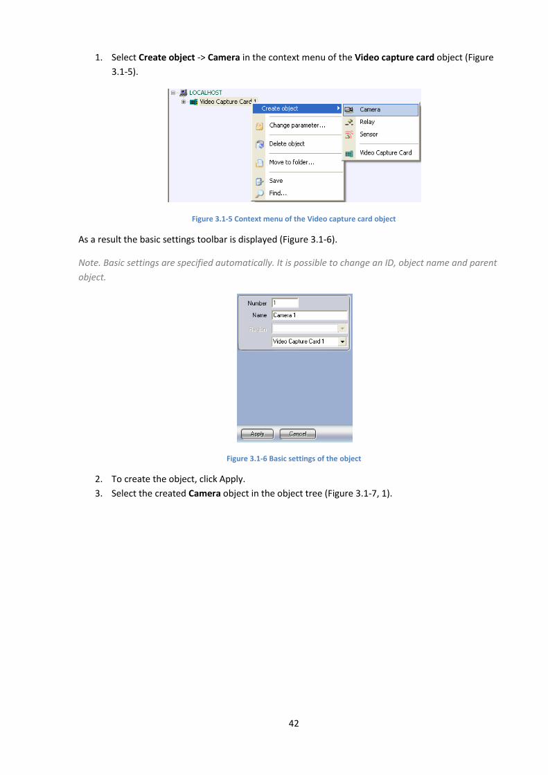
1. Select Create object -> Camera in the context menu of the Video capture card object (Figure
3.1-5).
Figure 3.1-5 Context menu of the Video capture card object
As a result the basic settings toolbar is displayed (Figure 3.1-6).
Note. Basic settings are specified automatically. It is possible to change an ID, object name and parent
object.
Figure 3.1-6 Basic settings of the object
2. To create the object, click Apply.
3. Select the created Camera object in the object tree (Figure 3.1-7, 1).
43
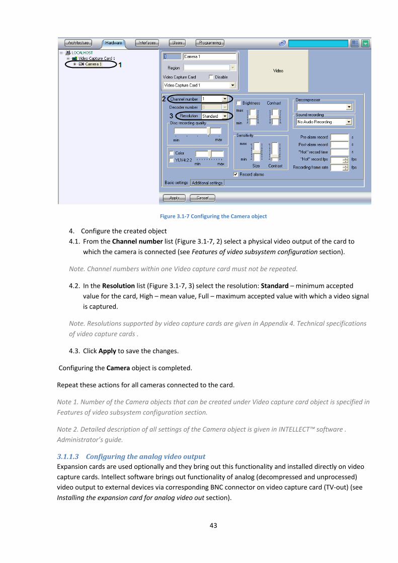
Figure 3.1-7 Configuring the Camera object
4. Configure the created object
4.1. From the Channel number list (Figure 3.1-7, 2) select a physical video output of the card to
which the camera is connected (see Features of video subsystem configuration section).
Note. Channel numbers within one Video capture card must not be repeated.
4.2. In the Resolution list (Figure 3.1-7, 3) select the resolution: Standard – minimum accepted
value for the card, High – mean value, Full – maximum accepted value with which a video signal
is captured.
Note. Resolutions supported by video capture cards are given in Appendix 4. Technical specifications
of video capture cards .
4.3. Click Apply to save the changes.
Configuring the Camera object is completed.
Repeat these actions for all cameras connected to the card.
Note 1. Number of the Camera objects that can be created under Video capture card object is specified in
Features of video subsystem configuration section.
Note 2. Detailed description of all settings of the Camera object is given in INTELLECT™ software .
Administrator’s guide.
3.1.1.3 Configuring the analog video output
Expansion cards are used optionally and they bring out this functionality and installed directly on video
capture cards. Intellect software brings out functionality of analog (decompressed and unprocessed)
video output to external devices via corresponding BNC connector on video capture card (TV-out) (see
Installing the expansion card for analog video out section).
44
Video outputting to analog monitor is made directly (without digitization) from on of the video cameras
connected to Server.
Note. Configuring Intellect take into account that outputting of analog video to analog monitor is
possible only from one camera.
For video outputting to analog monitor a video capture card must have an analog video output. An
analog video output is integrated into FS-8 video capture cards. An extra analog video output card
should be installed for FS-5, FS-6, FS-16 cards.
A video from any Server camera can be output to an analog monitor. By default, a video from the
camera connected to the same video capture card as a monitor can be output to an analog monitor. To
output a video from any camera connected to any video capture card on the Server, solder analog
outputs (interface cables) on all Server video capture cards.
Note. When an analog video out card is connected to a video capture card and analog monitor connector
to the corresponding BNC-connector on the video capture card, analog video outputting to analog
monitor is activated automatically.
To output the video from all cameras installed on the Server and connected to different video capture
cards, to one analog monitor (perhaps when analog video outputs of cards installed on the Server are
soldered) in tweaki.exe utility (Extended Intellect configuration) do the following:
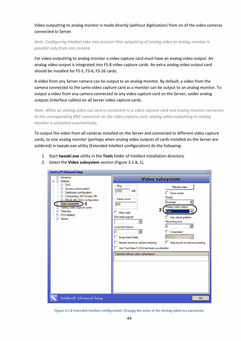
1. Start tweaki.exe utility in the Tools folder of Intellect installation directory.
2. Select the Video subsystem section (Figure 3.1-8, 1).
Figure 3.1-8 Extended Intellect configuration. Changig the value of the Analog video out parameter
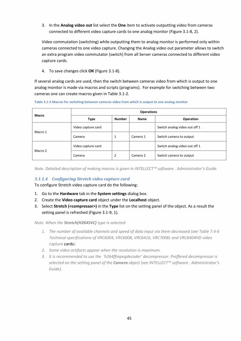
45
3. In the Analog video out list select the One item to activate outputting video from cameras
connected to different video capture cards to one analog monitor (Figure 3.1-8, 2).
Video commutation (switching) while outputting them to analog monitor is performed only within
cameras connected to one video capture. Changing the Analog video out parameter allows to switch
an extra program video commutator (switch) from all Server cameras connected to different video
capture cards.
4. To save changes click ОК (Figure 3.1-8).
If several analog cards are used, then the switch between cameras video from which is output to one
analog monitor is made via macros and scripts (programs). For example for switching between two
cameras one can create macros given in Table 3.1-2.
Table 3.1-2 Macros for switching between cameras video from which is output to one analog monitor
Macro Operations
Type Number Name Operation
Macro 1
Video capture card Switch analog video out off 1
Camera 1 Camera 1 Switch camera to output
Macro 2
Video capture card Switch analog video out off 1
Camera 2 Camera 2 Switch camera to output
Note. Detailed description of making macros is given in INTELLECT™ software . Administrator’s Guide.
3.1.1.4 Configuring Stretch video capture card
To configure Stretch video capture card do the following:
1. Go to the Hardware tab in the System settings dialog box.
2. Create the Video capture card object under the Localhost object.
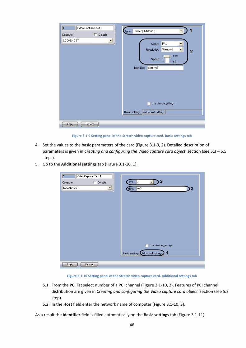
3. Select Stretch (<compressor>) in the Type list on the setting panel of the object. As a result the
setting panel is refreshed (Figure 3.1-9, 1).
Note. When the Stretch(H264SVC) type is selected:
1. The number of available channels and speed of data input via them decreased (see Table 7.4-6
Technical specifications of VRC6004, VRC6008, VRC6416, VRC7008L and VRC6404HD video
capture cards).
2. Some video artifacts appear when the resolution is maximum.
3. It is recommended to use the ‘h264ffmpegdecoder’ decompressor. Preffered decompressor is
selected on the setting panel of the Camera object (see INTELLECT™ software . Administrator’s
Guide).
46
Figure 3.1-9 Setting panel of the Stretch video capture card. Basic settings tab
4. Set the values to the basic parameters of the card (Figure 3.1-9, 2). Detailed description of
parameters is given in Creating and configuring the Video capture card object section (see 5.3 – 5.5
steps).
5. Go to the Additional settings tab (Figure 3.1-10, 1).
Figure 3.1-10 Setting panel of the Stretch video capture card. Additional settings tab
5.1. From the PCI list select number of a PCI channel (Figure 3.1-10, 2). Features of PCI channel
distribution are given in Creating and configuring the Video capture card object section (see 5.2
step).
5.2. In the Host field enter the network name of computer (Figure 3.1-10, 3).
As a result the Identifier field is filled automatically on the Basic settings tab (Figure 3.1-11).
47
Figure 3.1-11 The Identifier field. Basic settings tab
6. To save changes click Apply.
7. Configure cameras connected to Stretch video capture card (see Creating and configuring the
Camera object ).
Configuring Stretch video capture card is completed.
Note. IP Wizard can be used to configure Stretch video capture cards in INTELLECT™ software (see IP
Wizard section).
3.1.1.5 Configuring HikVision video capture card
To configure HikVision video capture card do the following:
1. Go to the Hardware tab in the System settings dialog box.
2. Create the Video capture card object under the Localhost object.
3. Select HikVision(<compressor>) in the Type list on the setting panel of the object.
Note. IP Wizard can be used to configure HikVision video capture cards in INTELLECT™ software (see IP
Wizard section).
3.1.2 Audio subsystem configuration
In INTELLECT™ software the audio subsystem is configured with the help of the Audio card objects
under which the Microphone objects (corresponding to connected audio devices) are created.
3.1.2.1 Creating and configuring the Audio card object
To create and configure the Audio card object, do the following:
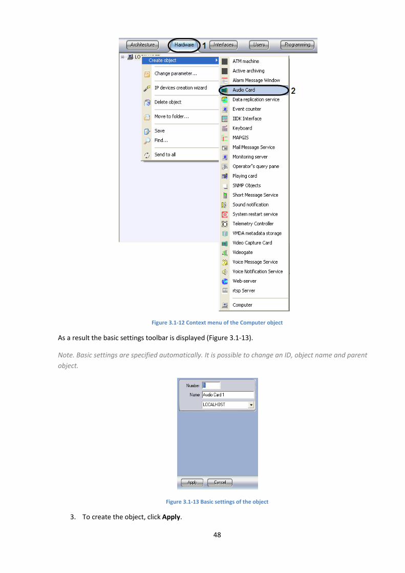
1. Go to the Hardware tab in the System settings dialog box (Figure 3.1-12, 1).
2. Select Create object -> Audio card in the context menu of the Computer object (Figure 3.1-12,
2).
48
Figure 3.1-12 Context menu of the Computer object
As a result the basic settings toolbar is displayed (Figure 3.1-13).
Note. Basic settings are specified automatically. It is possible to change an ID, object name and parent
object.
Figure 3.1-13 Basic settings of the object
3. To create the object, click Apply.

49
4. Select the created Audio card object in the object tree (Figure 3.1-14, 1).
Figure 3.1-14 Configuring the Audio card object
5. Configure the created object.
5.1. In the Board list (Figure 3.1-7, 2) specify the type and PCI channel of the card (Figure 3.1-14, 2).
Between the Audio cards objects there is end-to-end distribution of PCI channels that starts
with ‘0’.
5.2. In the Sample rate list select the audio sample rate (Figure 3.1-14, 3).
Note 1. Using channels from FS 5\6\16 cards set 8000, 16000 or 32000 sample rates while configuring
the LinuxHub audio card. Otherwise there is no guarantee of receiving audio from В противном случае
получение звука с плат FS5\6\16 cards.
Set another sample rate if audo is received only from the embedded audio card.
Note 2. Sample rate for FX HD4 (SA 7160PCI) card (specified in the Sample rate list) is to be the same as
the sample rate on the video camera. If rate values are not the same then slow-/fast- motion is possible.
5.3. Click Apply to save the changes.
Configuring the Audio card object is completed.
Attention! To configure one physical video capture card the creation of several Audio card objects is
required (see Features of audio subsystem configuration section).
3.1.2.2 Creating and configuring the Microphone object
To create and configure the Microphone object, do the following:
1. Select Create object -> Microphone in the context menu of the Audio card object (Figure
3.1-15).

50
Figure 3.1-15 Context menu of the Microphone object
As a result the basic settings toolbar is displayed (Figure 3.1-16).
Note. Basic settings are specified automatically. It is possible to change an ID, object name and parent
object.
Figure 3.1-16 Basic settings of the object
2. To create the object, click Apply.
3. Select the created Microphone object in the object tree (Figure 3.1-17, 1).
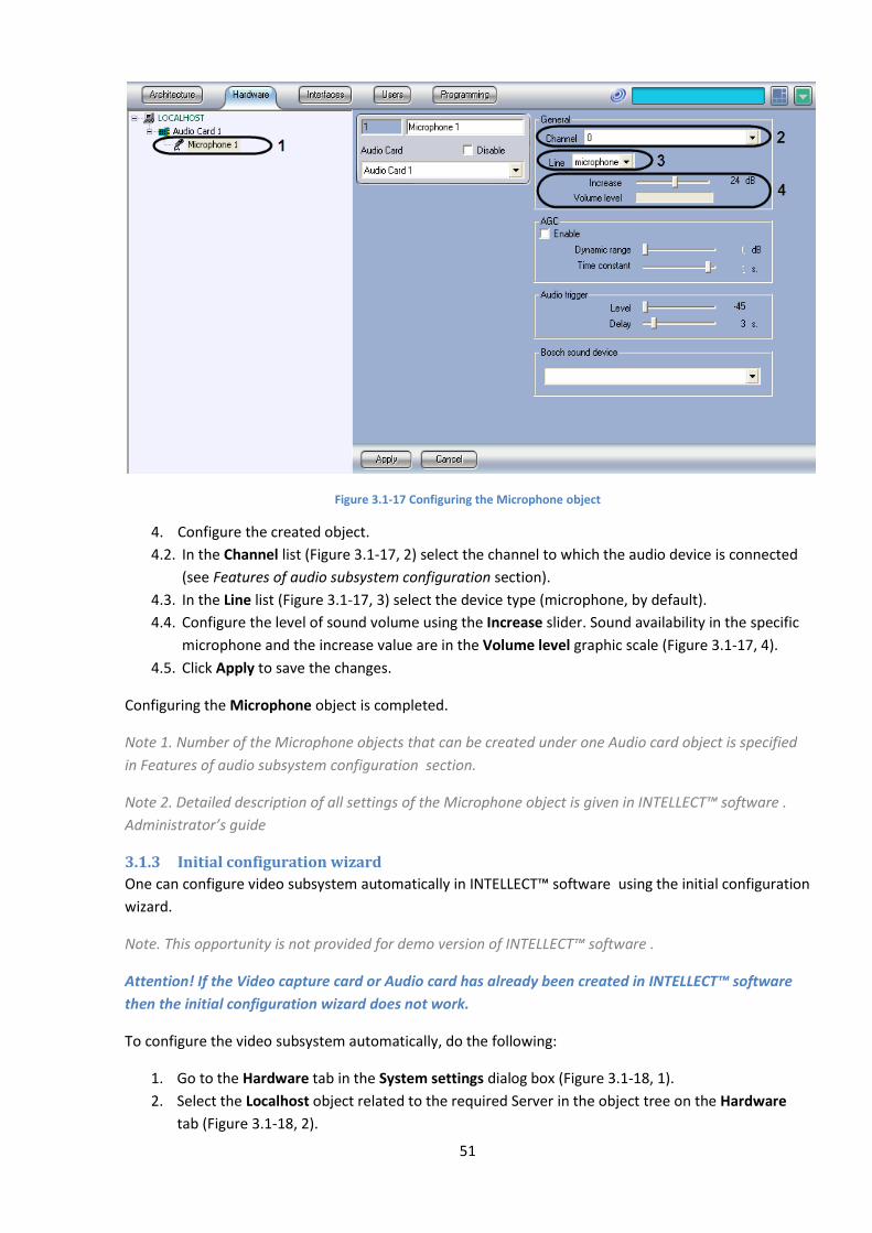
51
Figure 3.1-17 Configuring the Microphone object
4. Configure the created object.
4.2. In the Channel list (Figure 3.1-17, 2) select the channel to which the audio device is connected
(see Features of audio subsystem configuration section).
4.3. In the Line list (Figure 3.1-17, 3) select the device type (microphone, by default).
4.4. Configure the level of sound volume using the Increase slider. Sound availability in the specific
microphone and the increase value are in the Volume level graphic scale (Figure 3.1-17, 4).
4.5. Click Apply to save the changes.
Configuring the Microphone object is completed.
Note 1. Number of the Microphone objects that can be created under one Audio card object is specified
in Features of audio subsystem configuration section.
Note 2. Detailed description of all settings of the Microphone object is given in INTELLECT™ software .
Administrator’s guide
3.1.3 Initial configuration wizard
One can configure video subsystem automatically in INTELLECT™ software using the initial configuration
wizard.
Note. This opportunity is not provided for demo version of INTELLECT™ software .
Attention! If the Video capture card or Audio card has already been created in INTELLECT™ software
then the initial configuration wizard does not work.
To configure the video subsystem automatically, do the following:
1. Go to the Hardware tab in the System settings dialog box (Figure 3.1-18, 1).
2. Select the Localhost object related to the required Server in the object tree on the Hardware
tab (Figure 3.1-18, 2).

52
3. Click Initial configuration wizard on the settings panel of selected object (Figure 3.1-18, 3).
Figure 3.1-18 Initial configuration wizard
The Creating initial configuration of the video subsystem window is displayed (Figure 3.1-19).
Figure 3.1-19 Initial configuration wizard
4. To create initial configuration of the video subsystem, click ОК (Figure 3.1-19). This action will
add objects under Intellect software key.
As a result the created objects are displayed in the object tree (Figure 3.1-20).
Figure 3.1-20 Created objects

53
Note. The following objects are created as a result of initial configuration wizard working:
1. The Video capture card (указанные в ключе) objects that correspond to the physical video
capture cards (for example, 4 Video capture card objects are created for one FS6/16 video
capture card);
2. The Camera objects - one for each Video capture card object;
3. The Audio card object configurated for working with a local audio card;
4. The Microphone objects under the Audio card object (the number of the Microphone objects is
equal to the number of audio channels in the key).
Initial configuration wizard does not create other objects that are given in the key.
The automatic configuration of video subsystem is completed.
3.1.4 Configuring the Watchdog hardware performance tester
Hardware performance tester is for computer autoreboot in case of the Windows OS or main Intellect
software modules failure.
INTELLECT™ software allows configuring the Watchdog hardware performance tester when operating
with video capture cards that support this functionality (see Appendix 4. Technical specifications of
video capture cards ).
The Watchdog hardware performance tester on the Server with installed video capture cards is
configured in 3 stages:
1. Make sure that the Watchdog hardware performance tester is connected correctly (see
Connecting the Watchdog hardware performance tester section).
2. Activate the function of the Watchdog hardware performance tester on the setting panel of the
Video capture card object.
3. Verify the Watchdog hardware performance tester.
To activate and verify the Watchdog hardware performance tester, do the following:
1. Go to the Hardware tab in the System settings dialog box.
2. Set the Activate watchdog checkbox on the setting panel of the Video capture card object
corresponding to one ADC on the card to which the Watchdog is connected (Figure 3.1-21, 1).
Note 1. When FX4, FX8 and FX16 video capture cards are used set the Activate watchdog checkbox in
the settings of every Video capture card object created for the card to which the Watchdog is connected.
Note 2. The 07 PCI channel should be selected for one of the Video capture card objects corresponding to
the ADC of FS8 card for correct operation of the Watchdog hardware performance tester on FS8 video
capture card. At the same time the Watchdog hardware performance tester can be activated on the
setting panel of any Video capture card object of FS8 card.
3. To save changes click Apply (Figure 3.1-21, 2).
4. End the video.run process using the Windows task manager (Figure 3.1-22).
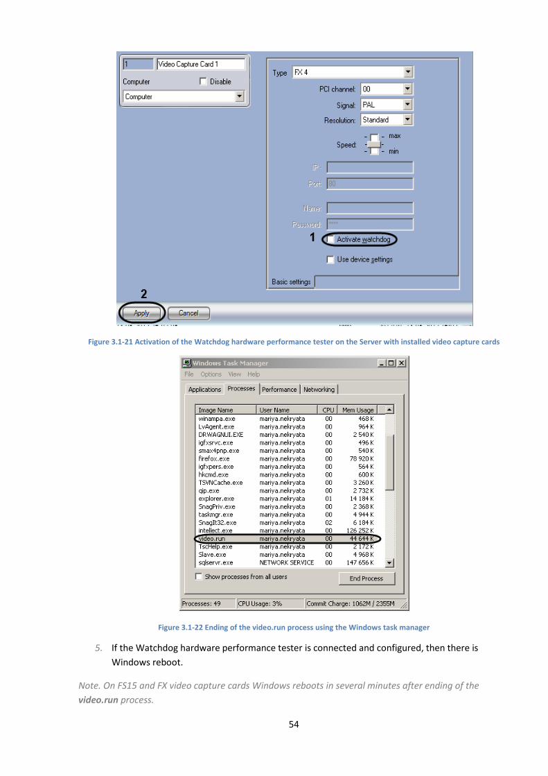
54
Figure 3.1-21 Activation of the Watchdog hardware performance tester on the Server with installed video capture cards
Figure 3.1-22 Ending of the video.run process using the Windows task manager
5. If the Watchdog hardware performance tester is connected and configured, then there is
Windows reboot.
Note. On FS15 and FX video capture cards Windows reboots in several minutes after ending of the
video.run process.
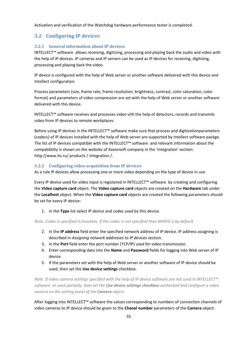
55
Activation and verification of the Watchdog hardware performance tester is completed.
3.2 Configuring IP devices
3.2.1 General information about IP devices
INTELLECT™ software allows receiving, digitizing, processing and playing back the audio and video with
the help of IP devices. IP cameras and IP servers can be used as IP devices for receiving, digitizing,
processing and playing back the video.
IP device is configured with the help of Web server or another software delivered with this device and
Intellect configuration.
Process parameters (size, frame rate, frame resolution, brightness, contrast, color saturation, color
format) and parameters of video compression are set with the help of Web server or another software
delivered with this device.
INTELLECT™ software receives and processes video vith the help of detectors, records and transmits
video from IP devices to remote workplaces.
Before using IP devices in the INTELLECT™ software make sure that process and digitizationparameters
(codecs) of IP devices installed with the help of Web server are supported by Intellect software packge.
The list of IP devices compatible with the INTELLECT™ software and relevant information about the
compatibility is shown on the website of Axxonsoft company in the ‘Integration’ section:
http://www.itv.ru/ products / integration /.
3.2.2 Configuring video acquisition from IP devices
As a rule IP devices allow processing one or more video depending on the type of device in use.
Every IP device used for video input is registered in INTELLECT™ software by creating and configuring
the Video capture card object. The Video capture card objects are created on the Hardware tab under
the Localhost object. When the Video capture card objects are created the following parameters should
be set for every IP device:
1. In the Type list select IP device and codec used by this device.
Note. Codec is specified in brackets. If the codec is not specified then MJPEG is by default.
2. In the IP address field enter the specified network address of IP device. IP address assigning is
described in Assigning network addresses to IP devices section.
3. In the Port field enter the port number (TCP/IP) used for video transmission.
4. Enter corresponding data into the Name and Password fields for logging into Web server of IP
device.
5. If the parameters set with the help of Web server or another software of IP device should be
used, then set the Use device settings checkbox.
Note. If video camera settings specified with the help of IP device software are not used in INTELLECT™
software or used partially, then set the Use device settings checkbox unchecked and configure a video
camera on the setting panel of the Camera object.
After logging into INTELLECT™ software the values corresponding to numbers of connection channels of
video cameras to IP device should be given to the Chanel number parameters of the Camera object.

56
Note. Set the 1 value for the Chanel number parameter when IP camera is configured. Otherwise IP
camera is nonworking.
3.2.3 Configuring audio acquisition from IP devices
Every IP device used for audio input is registered in the INTELLECT™ software by creating and
configuring the Audio card object. The Audio card objects are created on the Hardware tab under the
Localhost object. When the Audio card objects are created the values of short names of IP devices
should be set to the Card parameter for every IP device. Hover the cursor over the end of the Card line
and specify the IP address of the device, username and password for access to device (if specified).
Examples of configuring the Card parameter of the Audio card object for Axis video camera are given in
Figure 3.2-1.
А. when there is no username or password
B. when there is a username and password
Figure 3.2-1 Examples of configuring the Card parameter for Axis IP camera
When the Audio card is configured restart the INTELLECT™ software. Otherwise the audio subsystem
(particularly, microphones) can not be configured.
Microphones built into or connected to IP devices are registered in the INTELLECT™ software by creating
the Microphone objects under the Audio card object. Under one Audio card object there are the
Microphone objects in amount corresponding to the amount of audio input channels and restrictions
applied by a license key. Corresponding segment of hardware branch when IP device and one
microphone are registered is given in Figure 3.2-2.
Figure 3.2-2 Hardware branch when IP device and microphone are registered
When the Microphone object is created, select the channel number of connecting the microphone to
audio input device from the Channel dropdown list (Figure 3.2-2).
3.2.4 IP Wizard
To create IP devices in the INTELLECT™ software, do the following:
1. Go to the Hardware tab in the System settings dialog box (Figure 3.2-3, 1).
2. In the object tree select the Camera object corresponding to the configured Server (Figure 3.2-3,
2).
3. Click IP devices creation wizard on the setting panel of the selected object (Figure 3.2-3, 3).

57
Figure 3.2-3 The IP devices creation wizard window
As a result the IP Wizard window is displayed. Found IP devices are displayed on the top of the window
(Figure 3.2-5).
Note. The IP Wizard window can also be displayed by selecting the IP Wizard item in the context menu
of the Localhost object (Figure 3.2-4).
Figure 3.2-4 The IP Wizard item in the context menu of the Localhost object
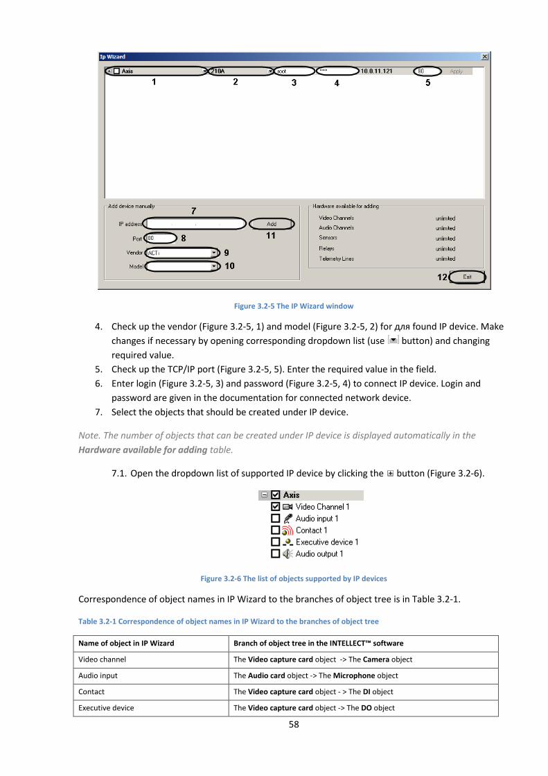
58
Figure 3.2-5 The IP Wizard window
4. Check up the vendor (Figure 3.2-5, 1) and model (Figure 3.2-5, 2) for для found IP device. Make
changes if necessary by opening corresponding dropdown list (use button) and changing
required value.
5. Check up the TCP/IP port (Figure 3.2-5, 5). Enter the required value in the field.
6. Enter login (Figure 3.2-5, 3) and password (Figure 3.2-5, 4) to connect IP device. Login and
password are given in the documentation for connected network device.
7. Select the objects that should be created under IP device.
Note. The number of objects that can be created under IP device is displayed automatically in the
Hardware available for adding table.
7.1. Open the dropdown list of supported IP device by clicking the button (Figure 3.2-6).
Figure 3.2-6 The list of objects supported by IP devices
Correspondence of object names in IP Wizard to the branches of object tree is in Table 3.2-1.
Table 3.2-1 Correspondence of object names in IP Wizard to the branches of object tree
Name of object in IP Wizard Branch of object tree in the INTELLECT™ software
Video channel The Video capture card object -> The Camera object
Audio input The Audio card object -> The Microphone object
Contact The Video capture card object - > The DI object
Executive device The Video capture card object -> The DO object
59
Name of object in IP Wizard Branch of object tree in the INTELLECT™ software
Telemetry line The Telemetry controller object -> The PTZ device object
Audio output The Playback card object -> The Loud speaker object
7.2. Set checkboxes for objects that should be created.
Note. To create/delete all objects set the checkboxes checked/unchecked for vendor of IP device.
8. Click Apply (Figure 3.2-5, 6).
The selected objects are created automatically in the Hardware object tree.
9. Repeat steps 4-8 for each IP device that should be created in the system.
Note. To delete the device from the IP Wizard window right – click the corresponding line in the table
and select the Delete camera <IP address> from the list item.
10. If the IP device is not found, then add it manually.
10.1. Enter the IP address of device in the IP address field (Figure 3.2-5, 7).
10.2. Enter the number of TCP/IP port in the Port field (Figure 3.2-5, 8).
10.3. Select the vendor of IP device in the Vendor dropdown list (Figure 3.2-5, 9).
10.4. Select the model of IP device in the Model dropdown list (Figure 3.2-5, 10).
10.5. Click Add (Figure 3.2-5, 11).
As a result The IP device with specified parameters is displayed in on the top of the window.
11. To complete the IP device creation step 6-8.
12. Click Exit to close the IP Wizard window (Figure 3.2-5, 12).
IP device creation is completed.
3.2.5 Features of IP device configuration
3.2.5.1 Features of Beward IP cameras configuration
By default port 80 is set for connecting to IP devices on the settings panel of the Video capture card
object. Enter the 5000 value in the Port field to connect to IP device of Beward B-9xx series and B-10xx
series (B-975W, B-970, B-915, B2.920, B-1070, B-1014 models and others).
3.2.5.2 Features of Panasonic IP devices (i-Pro series) configuration
When Panasonic IP-device (i-Pro series) is configured to compess in MPEG4 format, the Speed slider
controls videodata bitrate on the settings panel of the Video capture card object. When this parameter
is changed, both the speed of video stream and image quality are changed.
Note. WV-NP1000\1004, WV-F284, WV-NP240\244, WV-NS202 models and others are IP-devices (i-Pro
series).
Image from Panasonic IP device (i-Pro series) is displayed in the Monitor interface window with delay
from 15 sec to 1 min, depending on the model of the camera.

60
3.2.5.3 Features of TrendNet IP device configuration
TrendNet IP device is restarted when one of the following settings is changed on the settings panel of
the Video capture card object and/or Camera object:
1. Speed parameter(Video capture card);
2. Quality parameter (Camera);
3. Resolution parameter (Video capture card, Camera).
When the changes are saved, video disappears for about 1 min (time depends on the model of the
camera) and then it is restored with new parameters.
Note. TrendNet TV-IP312W, TV-IP212W, TV-IP110, TV-IP410 IP devices are restarted.
3.2.5.4 Features of Pelco Spectra IV IP device configuration
If Pelco Spectra IV IP device is configured to compress in MPEG4 format, then the Resolution dropdown
list on the settings panel of the Camera object is used for simultaneous configuration of three video
signal parameters:
1. Resolution;
2. Speed;
3. Compression quality.
At the same time the Speed (Video capture card object) and Quality (Camera object) parameters do not
interfere with the corresponding parameters of a video signal.
To set maximum quality, resolution and speed select the Full or High value from the Resolution
dropdown on the settings panel of the Camera object. The Standard value should be selected to set the
lowered compression quality of resolution and speed of video signal.
3.2.5.5 Features of AEBELL IP device configuration
By default port 80 is set for connecting to IP devices on the settings panel of the Video capture card
object. Enter the 36688 value in the Port field to connect to AEBELL BL-E704F IP server.
3.2.5.6 Features of Dynacolor IP device configuration
Dynacolor DynaHawk ZH-801+ IP device is restarted when one of the following settings is changed on
the settings panel of the Video capture card object and/or Camera object:
1. The Type parameter (Video capture card) – selection of Dynacolor (mjpeg) or
Dynacolor (mpeg-4) video stream compression format;
2. The Speed parameter (Video capture card);
3. The Quality parameter (Camera);
4. The Resolution parameter (Camera);
When the changes are saved, video disappears for about 1 min and then it is restored with new
parameters.

61
There can also be no video for about one minute when Intellect is started.
3.2.5.7 Features of Stream Labs IP device configuration
Note. Detailed description of the given devices can be found at http://www.ipstreamlabs.ru/products-
index.html
3.2.5.7.1 Features of Wave Cam M5 camera
1. Automatic brightness control. In this mode Intellect automatically uses internal algorithm of
image’s brightness control. This mode is enabled when the Brightness slider is set to a minimum
position. When there are no special requirements to the image, then this mode of brightness
control is recommended.
Note. Brightness can be controlled manually, moving the Brightness slider. 2. Video stream frame rate. Wave Cam M5 camera supports two channels of video displaying.
When only one video channel is engaged in Intellect, the video stream frame rate is 25 fps. When
both channels are engaged, frame rate of video stream for each channel is 12fps.
3. Telemetry. Wave Cam M5 camera is not a PTZ device. One can control some area of an image
with the help of video surveillance monitor. While configuring the Telemetry on a Wave Cam M5
camera, do the following:
3.1. Select the protocol of data exchange with a camera - IP-Camera (on the settings panel of
the Telemetry control object).
3.2. Apply PTZ device to the first video input channel (is set in the Channel number list on
the settings panel of the Camera object).
3.3. Apply telemetry control panel to the first video input channel (is set in the Channel
number list on the settings panel of the Camera object).
Note. The image will move through the second video input channel.
3.2.5.7.2 Features of Wave Server Enterprise hardware internetwork
1. Video stream frame rate. When only one camera is connected to Wave Server Enterprise
hardware internetwork, the video stream frame rate is 25 fps. When two or more cameras are
connected, total frame rate of processed video is 16 fps.
Note. If two video input channels are used, then frame rate of processed video is 16/2=8 fps. If there are
four video input channels, then 16/4=4 fps.
2. Telemetry. Telemetry is performed on a separate card with its own network interface. To
configure it, do the following:
2.1. Select the protocol of data exchange with camera with the help of which an analog camera
connected to the video server is controlled on the settings panel of the Telemetry control
object (for example, Pelco-D, Pelco-P, Panasonic-850).
2.2. Create two Video capture card objetcs.
Note. For every analog camera connected to Wave Server Enterprise, two Camera objects are necessary
to be created on the base of different Video capture card objects for video viewing and telemetry
configuration correspondingly.
62
3.2.5.7.3 Features of Wave Server WH1501 video server
Telemetry. When telemetry for Wave Server WH1501 video server is configured, it is necessary to select
protocol with the help of which the analog camera connected to the video server is controlled, on the
settings panel of the Telemetry control object (for example, Pelco-D, Pelco-P, Panasonic-850).
3.2.5.8 Features of Cisco IP device configuration
Cisco 4500 IP-device supports the following formats of video signal compression:
1. H.264;
2. MJPEG.
While setting the resolution the H.264 format has a higher priority than MJPEG: a possibility to set the
resolution for MJPEG exceeding the given for H.264, is not provided.
Priority difference leads to the following effects:
1. After changing the video capture card of the Cisco(h264) type for Cisco(mjpeg) with standard
video resolution,MJPEG video resolution can not be increased;
2. When the video capture cad of the Cisco(mjpeg) type is changed for Cisco(h264) with full video
resolution, the resolution will be changed from 704*576 to 1280*720. Resolution 720*576 will
be set after return to the Cisco(mjpeg) type.
Note. The type of a video capture card is selelcted from the Type dropdown list on the settings panel of
the Video capture card object. Video resolution is set with the use of analoguos parameter on the
settings panel of the Camera child object.
3.2.5.9 Features of Mobotix IP device configuration
Mobotix IP camera supports the following formats of video compression in Intellect:
1. MJPEG;
2. MxPEG.
Audio subsystem of Mobotix IP devices may be used when video is encoded in MxPEG.To choose this
format, select the Mobotix MxPEG value from the Type list on the settings panel of the Video capture
card object.
Note 1.When the Mobotix value is selected, video is received in MJPEG format and audio subsystem
functionality of IP device is not performed.
Note 2. Mobotix IP cameras that support sound are Q24M, D12, M22 and others. Detailed description of
these devices can be found at http://www.mobotix.ru/default.aspx
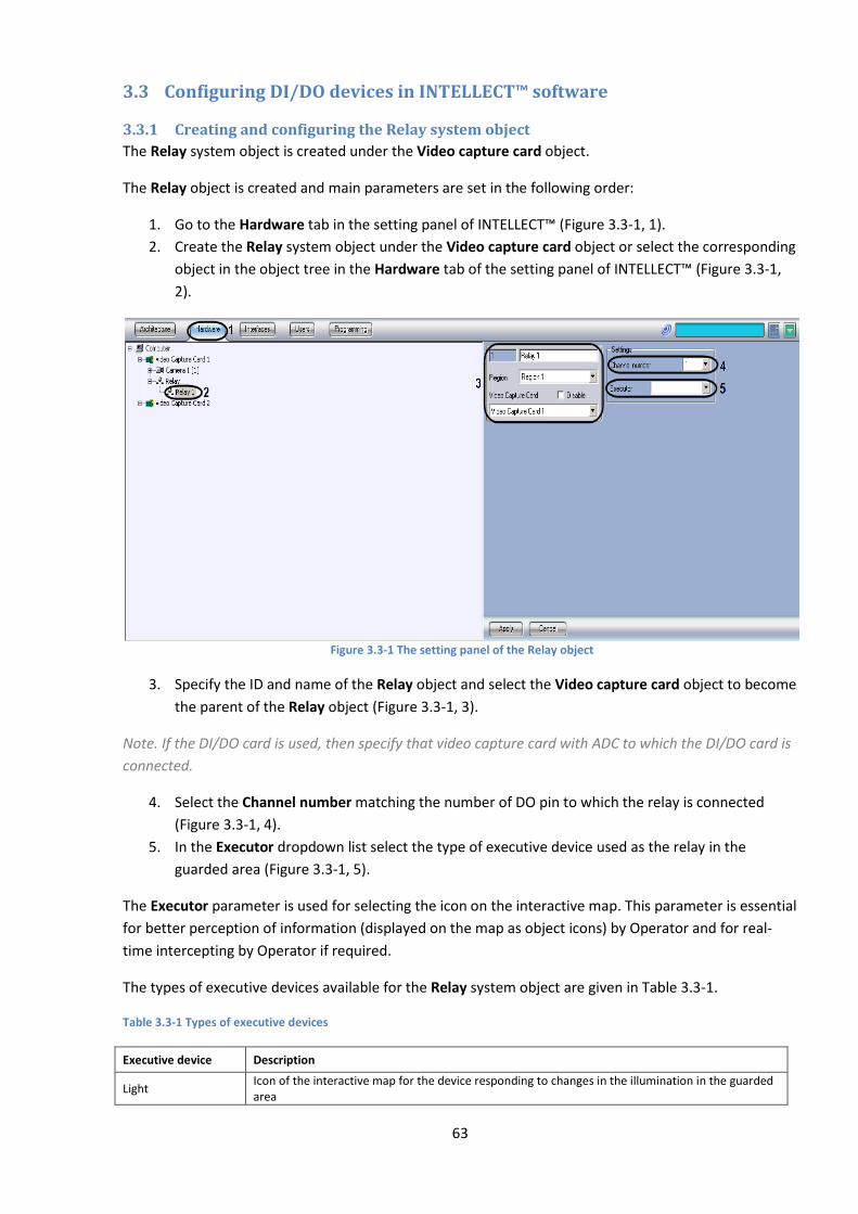
63
3.3 Configuring DI/DO devices in INTELLECT™ software
3.3.1 Creating and configuring the Relay system object
The Relay system object is created under the Video capture card object.
The Relay object is created and main parameters are set in the following order:
1. Go to the Hardware tab in the setting panel of INTELLECT™ (Figure 3.3-1, 1).
2. Create the Relay system object under the Video capture card object or select the corresponding
object in the object tree in the Hardware tab of the setting panel of INTELLECT™ (Figure 3.3-1,
2).
Figure 3.3-1 The setting panel of the Relay object
3. Specify the ID and name of the Relay object and select the Video capture card object to become
the parent of the Relay object (Figure 3.3-1, 3).
Note. If the DI/DO card is used, then specify that video capture card with ADC to which the DI/DO card is
connected.
4. Select the Channel number matching the number of DO pin to which the relay is connected
(Figure 3.3-1, 4).
5. In the Executor dropdown list select the type of executive device used as the relay in the
guarded area (Figure 3.3-1, 5).
The Executor parameter is used for selecting the icon on the interactive map. This parameter is essential
for better perception of information (displayed on the map as object icons) by Operator and for real-
time intercepting by Operator if required.
The types of executive devices available for the Relay system object are given in Table 3.3-1.
Table 3.3-1 Types of executive devices
Executive device Description
Light Icon of the interactive map for the device responding to changes in the illumination in the guarded area

64
Signal Icon of the interactive map for the device responding to sound changes in the guarded area
Lock Icon of the interactive map for the device responding to opening/closing of a window, door, etc.
6. Click Apply to save the changes.
Creating and configuring the Relay system object is completed.
3.3.2 Creating and configuring the Sensor system object
The Sensor system object is created under the Video capture card object.
The Sensor object is created and main parameters are set in the following order:
1. Go to the Hardware tab in the setting panel of INTELLECT™ (Figure 3.3-2, 1).
2. Create the Sensor system object under the Video capture card object or select the
corresponding object in the object tree in the Hardware tab of the setting panel of INTELLECT™
(Figure 3.3-2, 2).
Figure 3.3-2 The setting panel of the Sensor object
3. Specify the ID and name of the Sensor object and select the Video capture card object to
become the parent of the Sensor object (Figure 3.3-2, 3).
Note. If the DI/DO card is used, then specify that video capture card with ADC to which the DI/DO card is
connected.
4. Select the Channel number matching the number of DO pin to which the sensor is connected
(Figure 3.3-2, 4).
5. In the group of switches select the alarm mode: at switch on or at switch off. By default the
alarm at switch on mode is selected (Figure 3.3-2, 5).
The executive device corresponding to the Sensor system object operates at one of modes: alarm at
switch on or alarm at switch off.
Note. Sensors connected to Panasonic IP-devices (i-Pro series) trigger only at switch off.

65
When the alarm at switch off mode is selected, the normal state of the sensor is open. When the sensor
closes, it triggers and the corresponding actions are carried out in INTELLECT™.
6. In the Hardware dropdown list select the type of executive device used as the detector in the
guarded area (Figure 3.3-2, 6).
The Detector parameter is used for selecting the icon on the interactive map. This parameter is essential
for better perception of information (displayed on the map as object icons) by Operator and for real-
time intercepting by Operator if required.
Types of detectors available for the Sensor system object are given in Table 3.3-2.
Table 3.3-2 Types of detectors
Detector Description
Infrared Icon of the interactive map for the motion detectors
PIR Icon of the interactive map for the device on the ceiling of the guarded area
Glass Icon of the interactive map for the device on the window of the guarded area responding when the window is broken
Fire Icon of the interactive map for the device responding to changes of heat conditions in the guarded area
Window Icon of the interactive map for the device installed some distance away the window and responding when the window is broken
Smoke Icon of the interactive map for the device responding to smoke in the guarded area
Reed switch Icon of the interactive map for the device responding to opening/closing of a window, door, etc.
7. Click Apply to save the changes.
Creating and configuring the Sensor system object is completed.
3.3.3 Configuring DI/DO expansion cards
3.3.3.1 Connecting relays
If relays are connected to the DI/DO card, then up to 4 Relay objects can be created under the Video
capture card parent object.
All the Relay objects corresponding to relays connected to one DI/DO card are to be created in the
Hardware object tree under the Video capture card object corresponding to the video capture card
where the DI/DO card is installed.
If the DI/DO card is installed on FS-5, FS-6 or FS-16 video capture card, then the Relay objects are to be
created under any Video capture card object within the hardware card.
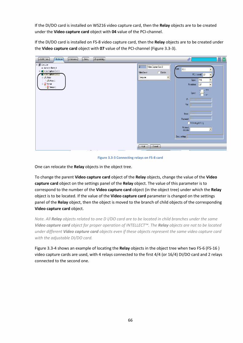
66
If the DI/DO card is installed on WS216 video capture card, then the Relay objects are to be created
under the Video capture card object with 04 value of the PCI-channel.
If the DI/DO card is installed on FS-8 video capture card, then the Relay objects are to be created under
the Video capture card object with 07 value of the PCI-channel (Figure 3.3-3).
Figure 3.3-3 Connecting relays on FS-8 card
One can relocate the Relay objects in the object tree.
To change the parent Video capture card object of the Relay objects, change the value of the Video
capture card object on the settings panel of the Relay object. The value of this parameter is to
correspond to the number of the Video capture card object (in the object tree) under which the Relay
object is to be located. If the value of the Video capture card parameter is changed on the settings
panel of the Relay object, then the object is moved to the branch of child objects of the corresponding
Video capture card object.
Note. All Relay objects related to one D I/DO card are to be located in child branches under the same
Video capture card object for proper operation of INTELLECT™. The Relay objects are not to be located
under different Video capture card objects even if these objects represent the same video capture card
with the adjustable DI/DO card.
Figure 3.3-4 shows an example of locating the Relay objects in the object tree when two FS-6 (FS-16 )
video capture cards are used, with 4 relays connected to the first 4/4 (or 16/4) DI/DO card and 2 relays
connected to the second one.
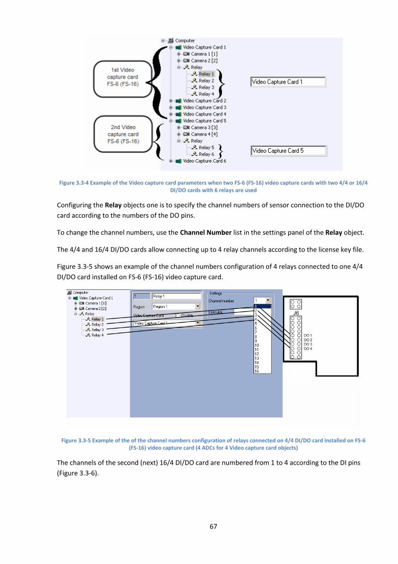
67
Figure 3.3-4 Example of the Video capture card parameters when two FS-6 (FS-16) video capture cards with two 4/4 or 16/4 DI/DO cards with 6 relays are used
Configuring the Relay objects one is to specify the channel numbers of sensor connection to the DI/DO
card according to the numbers of the DO pins.
To change the channel numbers, use the Channel Number list in the settings panel of the Relay object.
The 4/4 and 16/4 DI/DO cards allow connecting up to 4 relay channels according to the license key file.
Figure 3.3-5 shows an example of the channel numbers configuration of 4 relays connected to one 4/4
DI/DO card installed on FS-6 (FS-16) video capture card.
Figure 3.3-5 Example of the of the channel numbers configuration of relays connected on 4/4 DI/DO card installed on FS-6 (FS-16) video capture card (4 ADCs for 4 Video capture card objects)
The channels of the second (next) 16/4 DI/DO card are numbered from 1 to 4 according to the DI pins
(Figure 3.3-6).

68
Figure 3.3-6 Example of the of the channel numbers configuration of relays connected on the second (next) 16/4 DI/DO card installed on FS-6 (FS-16) video capture card (4 ADCs for 4 Video capture card objects)
3.3.3.2 Connecting sensors via 4/4 DI/DO card
One can create up to 4 Sensor objects under the Video capture card object when 4/4 DI/DO card is
installed.
All the Sensor objects corresponding to sensors connected to one 4/4 DI/DO card are to be created in
the Hardware object tree under the Video capture card object corresponding to the video capture card
where the DI/DO card is installed.
If the DI/DO card is installed on FS-5, FS-6 or FS-16 video capture card, then the Sensor objects are to be
created under any Video capture card object within the hardware card.
If the DI/DO card is installed on WS216 video capture card, then the Sensor objects are to be created
under the Video capture card object with 00 value of the PCI-channel.
If the DI/DO card is installed on FS-8 video capture card, then the Sensor objects are to be created under
the Video capture card object with 07 value of the PCI-channel (Figure 3.3-7).
Figure 3.3-7 Connecting sensors on FS-8 card

69
One can relocate the Sensor objects in the object tree. To change the parent Video capture card object
of the Sensor objects, change the value of the Video capture card object on the settings panel of the
Sensor object. The value of this parameter is to correspond to the number of the Video capture card
object (in the object tree) under which the Sensor object is to be located. If the value of the Video
capture card parameter is changed on the settings panel of the Sensor object, then the object is moved
to the branch of child objects of the corresponding Video capture card object.
Note. All Sensor objects related to one D I/DO card are to be located in child branches under the same
Video capture card object for proper operation of INTELLECT™. The Sensor objects are not to be located
under different Video capture card objects even if these objects represent the same video capture card
with the adjustable DI/DO card.
Figure 3.3-8 shows an example of locating the Sensor objects in the object tree when two FS-6 (FS-16 )
video capture cards are used, with 4 sensors connected to the first 4/4 DI/DO card and 2 sensors
connected to the second one.
Figure 3.3-8 Example of the Video capture card parameters when two FS-6 (FS-16) video capture cards with two 4/4 or 16/4 DI/DO cards with 6 sensors are used
Configuring the Sensor objects one is to specify the channel numbers of sensor connection to the DI/DO
card according to the numbers of the DO pins.
To change the channel numbers, use the Channel Number list in the settings panel of the Sensor object.
4/4 DI/DO card allows connecting up to 4 sensor channels according to the license key file.
Figure 3.3-9 shows an example of the channel numbers configuration of 4 sensors connected to one 4/4
DI/DO card installed on FS-6 (FS-16) video capture card.
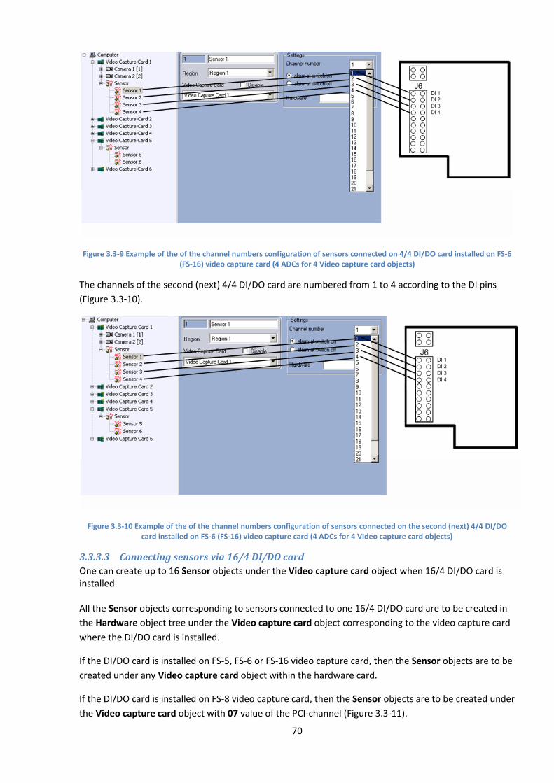
70
Figure 3.3-9 Example of the of the channel numbers configuration of sensors connected on 4/4 DI/DO card installed on FS-6 (FS-16) video capture card (4 ADCs for 4 Video capture card objects)
The channels of the second (next) 4/4 DI/DO card are numbered from 1 to 4 according to the DI pins
(Figure 3.3-10).
Figure 3.3-10 Example of the of the channel numbers configuration of sensors connected on the second (next) 4/4 DI/DO card installed on FS-6 (FS-16) video capture card (4 ADCs for 4 Video capture card objects)
3.3.3.3 Connecting sensors via 16/4 DI/DO card
One can create up to 16 Sensor objects under the Video capture card object when 16/4 DI/DO card is installed. All the Sensor objects corresponding to sensors connected to one 16/4 DI/DO card are to be created in
the Hardware object tree under the Video capture card object corresponding to the video capture card
where the DI/DO card is installed.
If the DI/DO card is installed on FS-5, FS-6 or FS-16 video capture card, then the Sensor objects are to be
created under any Video capture card object within the hardware card.
If the DI/DO card is installed on FS-8 video capture card, then the Sensor objects are to be created under
the Video capture card object with 07 value of the PCI-channel (Figure 3.3-11).
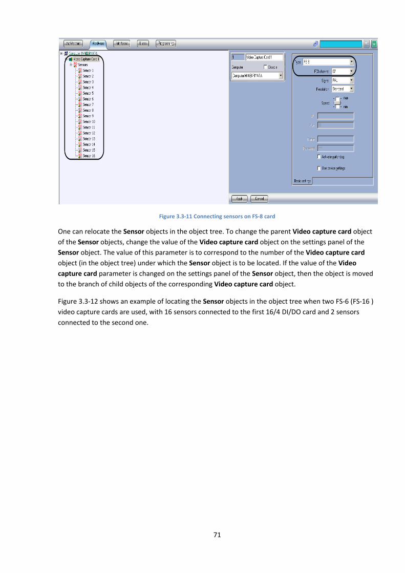
71
Figure 3.3-11 Connecting sensors on FS-8 card
One can relocate the Sensor objects in the object tree. To change the parent Video capture card object
of the Sensor objects, change the value of the Video capture card object on the settings panel of the
Sensor object. The value of this parameter is to correspond to the number of the Video capture card
object (in the object tree) under which the Sensor object is to be located. If the value of the Video
capture card parameter is changed on the settings panel of the Sensor object, then the object is moved
to the branch of child objects of the corresponding Video capture card object.
Figure 3.3-12 shows an example of locating the Sensor objects in the object tree when two FS-6 (FS-16 )
video capture cards are used, with 16 sensors connected to the first 16/4 DI/DO card and 2 sensors
connected to the second one.
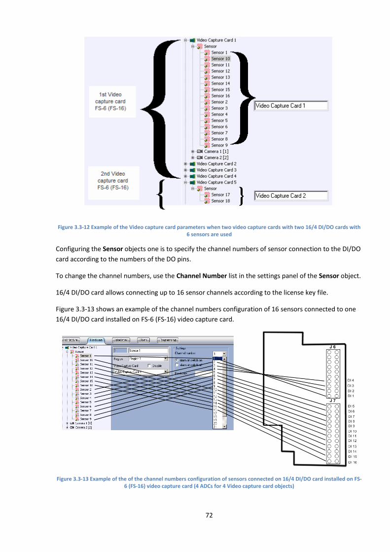
72
Figure 3.3-12 Example of the Video capture card parameters when two video capture cards with two 16/4 DI/DO cards with 6 sensors are used
Configuring the Sensor objects one is to specify the channel numbers of sensor connection to the DI/DO
card according to the numbers of the DO pins.
To change the channel numbers, use the Channel Number list in the settings panel of the Sensor object.
16/4 DI/DO card allows connecting up to 16 sensor channels according to the license key file.
Figure 3.3-13 shows an example of the channel numbers configuration of 16 sensors connected to one
16/4 DI/DO card installed on FS-6 (FS-16) video capture card.
Figure 3.3-13 Example of the of the channel numbers configuration of sensors connected on 16/4 DI/DO card installed on FS-6 (FS-16) video capture card (4 ADCs for 4 Video capture card objects)
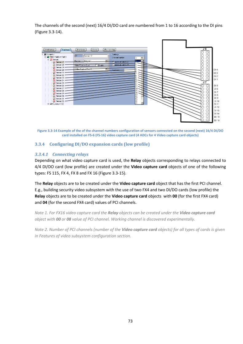
73
The channels of the second (next) 16/4 DI/DO card are numbered from 1 to 16 according to the DI pins
(Figure 3.3-14).
Figure 3.3-14 Example of the of the channel numbers configuration of sensors connected on the second (next) 16/4 DI/DO card installed on FS-6 (FS-16) video capture card (4 ADCs for 4 Video capture card objects)
3.3.4 Configuring DI/DO expansion cards (low profile)
3.3.4.1 Connecting relays
Depending on what video capture card is used, the Relay objects corresponding to relays connected to
4/4 DI/DO card (low profile) are created under the Video capture card objects of one of the following
types: FS 115, FX 4, FX 8 and FX 16 (Figure 3.3-15).
The Relay objects are to be created under the Video capture card object that has the first PCI channel.
E.g., building security video subsystem with the use of two FX4 and two DI/DO cards (low profile) the
Relay objects are to be created under the Video capture card objects with 00 (for the first FX4 card)
and 04 (for the second FX4 card) values of PCI channels.
Note 1. For FX16 video capture card the Relay objects can be created under the Video capture card
object with 00 or 08 value of PCI channel. Working channel is discovered experimentally.
Note 2. Number of PCI channels (number of the Video capture card objects) for all types of cards is given
in Features of video subsystem configuration section.
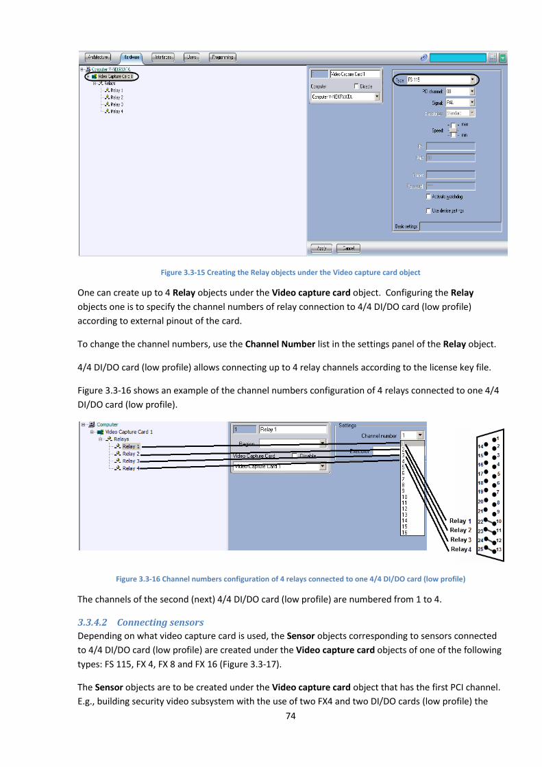
74
Figure 3.3-15 Creating the Relay objects under the Video capture card object
One can create up to 4 Relay objects under the Video capture card object. Configuring the Relay
objects one is to specify the channel numbers of relay connection to 4/4 DI/DO card (low profile)
according to external pinout of the card.
To change the channel numbers, use the Channel Number list in the settings panel of the Relay object.
4/4 DI/DO card (low profile) allows connecting up to 4 relay channels according to the license key file.
Figure 3.3-16 shows an example of the channel numbers configuration of 4 relays connected to one 4/4
DI/DO card (low profile).
Figure 3.3-16 Channel numbers configuration of 4 relays connected to one 4/4 DI/DO card (low profile)
The channels of the second (next) 4/4 DI/DO card (low profile) are numbered from 1 to 4.
3.3.4.2 Connecting sensors
Depending on what video capture card is used, the Sensor objects corresponding to sensors connected
to 4/4 DI/DO card (low profile) are created under the Video capture card objects of one of the following
types: FS 115, FX 4, FX 8 and FX 16 (Figure 3.3-17).
The Sensor objects are to be created under the Video capture card object that has the first PCI channel.
E.g., building security video subsystem with the use of two FX4 and two DI/DO cards (low profile) the
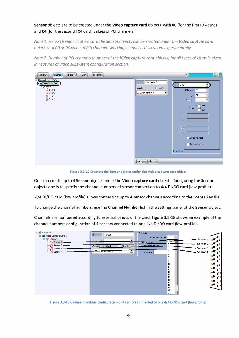
75
Sensor objects are to be created under the Video capture card objects with 00 (for the first FX4 card)
and 04 (for the second FX4 card) values of PCI channels.
Note 1. For FX16 video capture card the Sensor objects can be created under the Video capture card
object with 00 or 08 value of PCI channel. Working channel is discovered experimentally.
Note 2. Number of PCI channels (number of the Video capture card objects) for all types of cards is given
in Features of video subsystem configuration section.
Figure 3.3-17 Creating the Sensor objects under the Video capture card object
One can create up to 4 Sensor objects under the Video capture card object. Configuring the Sensor
objects one is to specify the channel numbers of sensor connection to 4/4 DI/DO card (low profile).
4/4 DI/DO card (low profile) allows connecting up to 4 sensor channels according to the license key file.
To change the channel numbers, use the Channel Number list in the settings panel of the Sensor object.
Channels are numbered according to external pinout of the card. Figure 3.3-18 shows an example of the
channel numbers configuration of 4 sensors connected to one 4/4 DI/DO card (low profile).
Figure 3.3-18 Channel numbers configuration of 4 sensors connected to one 4/4 DI/DO card (low profile)
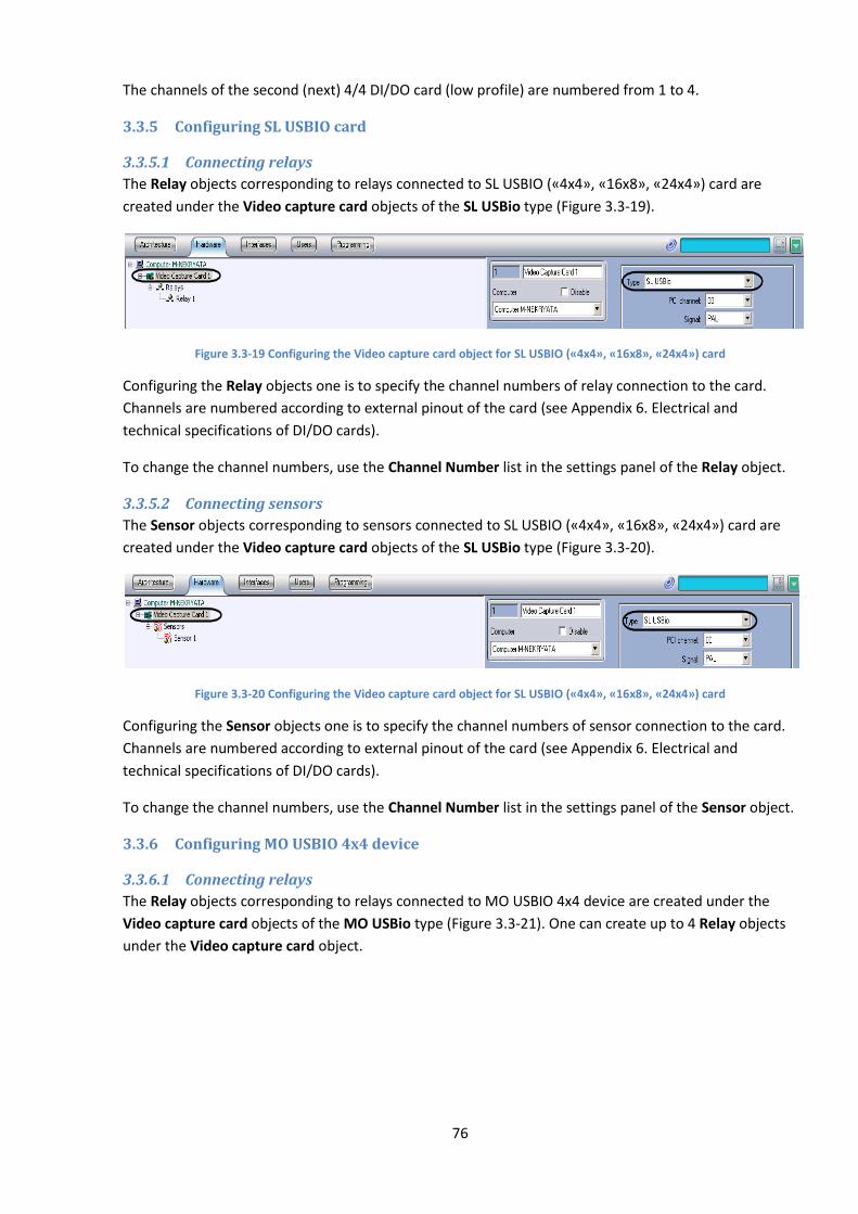
76
The channels of the second (next) 4/4 DI/DO card (low profile) are numbered from 1 to 4.
3.3.5 Configuring SL USBIO card
3.3.5.1 Connecting relays
The Relay objects corresponding to relays connected to SL USBIO («4x4», «16x8», «24x4») card are
created under the Video capture card objects of the SL USBio type (Figure 3.3-19).
Figure 3.3-19 Configuring the Video capture card object for SL USBIO («4x4», «16x8», «24x4») card
Configuring the Relay objects one is to specify the channel numbers of relay connection to the card.
Channels are numbered according to external pinout of the card (see Appendix 6. Electrical and
technical specifications of DI/DO cards).
To change the channel numbers, use the Channel Number list in the settings panel of the Relay object.
3.3.5.2 Connecting sensors
The Sensor objects corresponding to sensors connected to SL USBIO («4x4», «16x8», «24x4») card are
created under the Video capture card objects of the SL USBio type (Figure 3.3-20).
Figure 3.3-20 Configuring the Video capture card object for SL USBIO («4x4», «16x8», «24x4») card
Configuring the Sensor objects one is to specify the channel numbers of sensor connection to the card.
Channels are numbered according to external pinout of the card (see Appendix 6. Electrical and
technical specifications of DI/DO cards).
To change the channel numbers, use the Channel Number list in the settings panel of the Sensor object.
3.3.6 Configuring MO USBIO 4х4 device
3.3.6.1 Connecting relays
The Relay objects corresponding to relays connected to MO USBIO 4x4 device are created under the
Video capture card objects of the MO USBio type (Figure 3.3-21). One can create up to 4 Relay objects
under the Video capture card object.
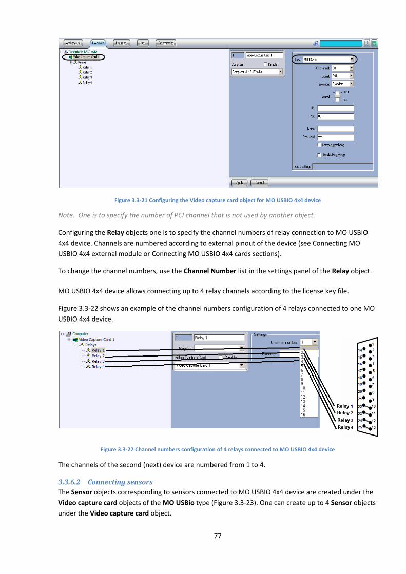
77
Figure 3.3-21 Configuring the Video capture card object for MO USBIO 4x4 device
Note. One is to specify the number of PCI channel that is not used by another object.
Configuring the Relay objects one is to specify the channel numbers of relay connection to MO USBIO
4x4 device. Channels are numbered according to external pinout of the device (see Connecting MO
USBIO 4х4 external module or Connecting MO USBIO 4x4 cards sections).
To change the channel numbers, use the Channel Number list in the settings panel of the Relay object.
MO USBIO 4x4 device allows connecting up to 4 relay channels according to the license key file.
Figure 3.3-22 shows an example of the channel numbers configuration of 4 relays connected to one MO
USBIO 4x4 device.
Figure 3.3-22 Channel numbers configuration of 4 relays connected to MO USBIO 4x4 device
The channels of the second (next) device are numbered from 1 to 4.
3.3.6.2 Connecting sensors
The Sensor objects corresponding to sensors connected to MO USBIO 4x4 device are created under the
Video capture card objects of the MO USBio type (Figure 3.3-23). One can create up to 4 Sensor objects
under the Video capture card object.
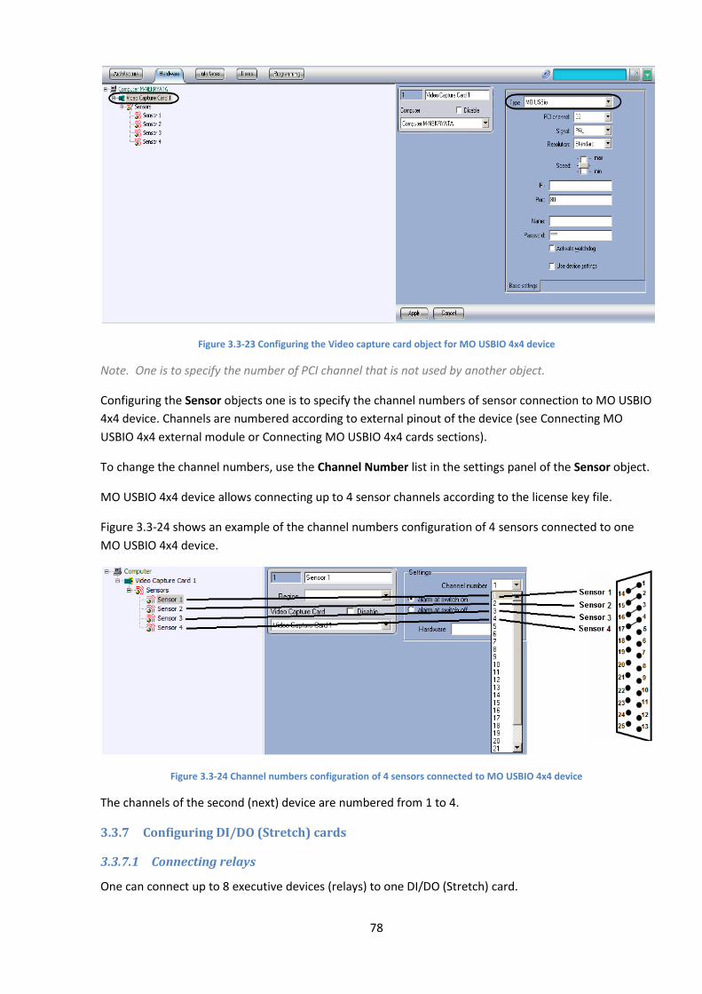
78
Figure 3.3-23 Configuring the Video capture card object for MO USBIO 4x4 device
Note. One is to specify the number of PCI channel that is not used by another object.
Configuring the Sensor objects one is to specify the channel numbers of sensor connection to MO USBIO
4x4 device. Channels are numbered according to external pinout of the device (see Connecting MO
USBIO 4х4 external module or Connecting MO USBIO 4x4 cards sections).
To change the channel numbers, use the Channel Number list in the settings panel of the Sensor object.
MO USBIO 4x4 device allows connecting up to 4 sensor channels according to the license key file.
Figure 3.3-24 shows an example of the channel numbers configuration of 4 sensors connected to one
MO USBIO 4x4 device.
Figure 3.3-24 Channel numbers configuration of 4 sensors connected to MO USBIO 4x4 device
The channels of the second (next) device are numbered from 1 to 4.
3.3.7 Configuring DI/DO (Stretch) cards
3.3.7.1 Connecting relays
One can connect up to 8 executive devices (relays) to one DI/DO (Stretch) card.

79
The Relay objects corresponding to relays connected to DI/DO (Stretch) card are created under the
Video capture card objects of the Stretch type (Figure 3.3-25).
Figure 3.3-25 Creating the Relay objects under the Video capture card object of Stretch type
Configuring the Relay objects one is to specify the channel numbers of relay connection to the card.
Channels are numbered according to external pinout of the card (see Connecting DI/DO (Stretch)
section).
To change the channel numbers, use the Channel Number list in the settings panel of the Relay object.
3.3.7.2 Connecting sensors
One can connect up to 8 sensors to one DI/DO (Stretch) card.
The Sensor objects corresponding to sensors connected to DI/DO (Stretch) card are created under the
Video capture card objects of the Stretch type (Figure 3.3-26).
Figure 3.3-26 Creating the Sensor objects under the Video capture card object of Stretch type
Configuring the Sensor objects one is to specify the channel numbers of sensor connection to the card.
Channels are numbered according to external pinout of the card (see Connecting DI/DO (Stretch)
section).
To change the channel numbers, use the Channel Number list in the settings panel of the Sensor object.
3.3.8 Configuring sensors and relays connected via IP devices
If relays are connected to Server via IP devices, then select the corresponding type of IP device on the
setting panel of the Video capture card object; set IP address, name and password to connect to camera
(see Configuring IP devices section).
Note. If relays are connected to Server via Bosh IP device, then enter the service value in the Name field
(Figure 3.3-27). With another value the functionality of the relay is not performed on Server.
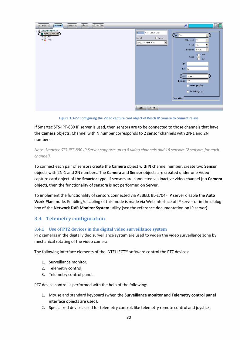
80
Figure 3.3-27 Configuring the Video capture card object of Bosch IP camera to connect relays
If Smartec STS-IPT-880 IP server is used, then sensors are to be connected to those channels that have
the Camera objects. Channel with N number corresponds to 2 sensor channels with 2N-1 and 2N
numbers.
Note. Smartec STS-IPT-880 IP Server supports up to 8 video channels and 16 sensors (2 sensors for each
channel).
To connect each pair of sensors create the Camera object with N channel number, create two Sensor
objects with 2N-1 and 2N numbers. The Camera and Sensor objects are created under one Video
capture card object of the Smartec type. If sensors are connected via inactive video channel (no Camera
object), then the functionality of sensora is not performed on Server.
To implement the functionality of sensors connected via AEBELL BL-E704F IP server disable the Auto
Work Plan mode. Enabling/disabling of this mode is made via Web interface of IP server or in the dialog
box of the Network DVR Monitor System utility (see the reference documentation on IP server).
3.4 Telemetry configuration
3.4.1 Use of PTZ devices in the digital video surveillance system
PTZ cameras in the digital video surveillance system are used to widen the video surveillance zone by
mechanical rotating of the video camera.
The following interface elements of the INTELLECT™ software control the PTZ devices:
1. Surveillance monitor;
2. Telemetry control;
3. Telemetry control panel.
PTZ device control is performed with the help of the following:
1. Mouse and standard keyboard (when the Surveillance monitor and Telemetry control panel
interface objects are used).
2. Specialized devices used for telemetry control, like telemetry remote control and joystick.
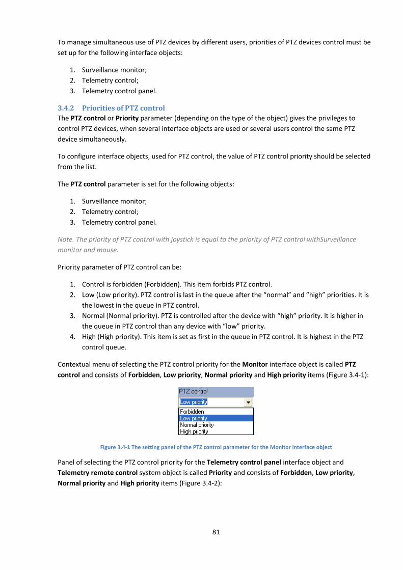
81
To manage simultaneous use of PTZ devices by different users, priorities of PTZ devices control must be
set up for the following interface objects:
1. Surveillance monitor;
2. Telemetry control;
3. Telemetry control panel.
3.4.2 Priorities of PTZ control
The PTZ control or Priority parameter (depending on the type of the object) gives the privileges to
control PTZ devices, when several interface objects are used or several users control the same PTZ
device simultaneously.
To configure interface objects, used for PTZ control, the value of PTZ control priority should be selected
from the list.
The PTZ control parameter is set for the following objects:
1. Surveillance monitor;
2. Telemetry control;
3. Telemetry control panel.
Note. The priority of PTZ control with joystick is equal to the priority of PTZ control withSurveillance
monitor and mouse.
Priority parameter of PTZ control can be:
1. Control is forbidden (Forbidden). This item forbids PTZ control.
2. Low (Low priority). PTZ control is last in the queue after the “normal” and “high” priorities. It is
the lowest in the queue in PTZ control.
3. Normal (Normal priority). PTZ is controlled after the device with “high” priority. It is higher in
the queue in PTZ control than any device with “low” priority.
4. High (High priority). This item is set as first in the queue in PTZ control. It is highest in the PTZ
control queue.
Contextual menu of selecting the PTZ control priority for the Monitor interface object is called PTZ
control and consists of Forbidden, Low priority, Normal priority and High priority items (Figure 3.4-1):
Figure 3.4-1 The setting panel of the PTZ control parameter for the Monitor interface object
Panel of selecting the PTZ control priority for the Telemetry control panel interface object and
Telemetry remote control system object is called Priority and consists of Forbidden, Low priority,
Normal priority and High priority items (Figure 3.4-2):
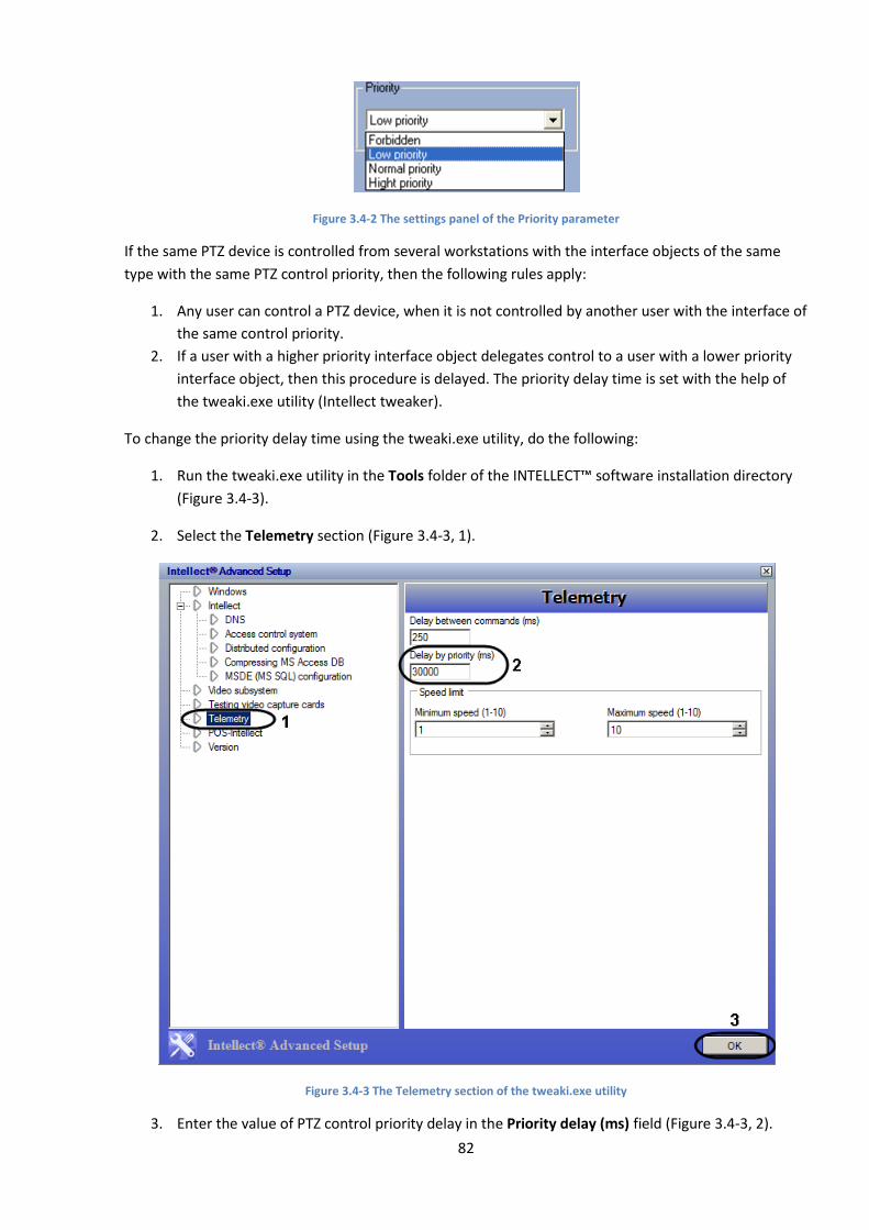
82
Figure 3.4-2 The settings panel of the Priority parameter
If the same PTZ device is controlled from several workstations with the interface objects of the same
type with the same PTZ control priority, then the following rules apply:
1. Any user can control a PTZ device, when it is not controlled by another user with the interface of
the same control priority.
2. If a user with a higher priority interface object delegates control to a user with a lower priority
interface object, then this procedure is delayed. The priority delay time is set with the help of
the tweaki.exe utility (Intellect tweaker).
To change the priority delay time using the tweaki.exe utility, do the following:
1. Run the tweaki.exe utility in the Tools folder of the INTELLECT™ software installation directory
(Figure 3.4-3).
2. Select the Telemetry section (Figure 3.4-3, 1).
Figure 3.4-3 The Telemetry section of the tweaki.exe utility
3. Enter the value of PTZ control priority delay in the Priority delay (ms) field (Figure 3.4-3, 2).

83
The delay parameter is given in milliseconds. The default value is 30000.
4. Click OK to save the changes (Figure 3.4-3, 3).
Note. When the objects are configured with variable PTZ priority controls it is recommended to assign
different PTZ control priorities to different system objects (object types). If different system objects have
the same PTZ control priority, problems may occur in operation, especially in controlling the PTZ devices.
3.4.3 PTZ device (telemetry) configuration
3.4.3.1 Sequence of PTZ device configuration
PTZ device configuration in the INTELLECT™ software consists of creation and configuration of system
objects corresponding to the PTZ module, and user interface for PTZ device operation.
The user interface for PTZ device operation is represented by the following interface objects:
1. Telemetry control;
2. Operator window;
3. Surveillance monitor.
To configure PTZ devices and control panels do the following:
1. Configuration of Server ports for PTZ connection.
2. PTZ configuration.
3. Telemetry control panel configuration.
4. Telemetry control configuration.
5. Configuration of Operator window for telemetry control (PTZ devices of certain type).
6. Configuration of Surveillance monitor to control PTZ device with the help of mouse or joystick.
3.4.3.2 Configuration of Server ports and remote workplace for PTZ connection
PTZ devices are connected to the Server serial ports (COM). The INTELLECT™ software has the facility to
plug in the required number of PTZ devices on demand.
Data exchange with a PTZ device is performed via the serial port (COM) in accordance with special
protocol. Any type of PTZ devices has its own individual exchange protocol. Only one exchange protocol
can be selected for data exchange via the serial port (COM). In this connection only one type of PTZ
devices may be connected to one serial port (COM).
Configuration of several serial ports (COM) is performed in turn. Each type of serial ports (COM), used to
connect the PTZ device, has the corresponding Telemetry card object, created and configured on the
Hardware tab in the System settings dialog box.
To configure the serial port (COM) used for connecting PTZ devices of the same type, do the following:
1. Go to the Hardware tab in the System settings dialog box (Figure 3.4-4, 1).
2. Create the Telemetry card system object under the Computer object or select the
corresponding object in the object tree on the Hardware tab in the System settings dialog box
(Figure 3.4-4, 2).
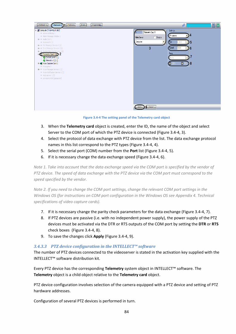
84
Figure 3.4-4 The setting panel of the Telemetry card object
3. When the Telemetry card object is created, enter the ID, the name of the object and select
Server to the COM port of which the PTZ device is connected (Figure 3.4-4, 3).
4. Select the protocol of data exchange with PTZ device from the list. The data exchange protocol
names in this list correspond to the PTZ types (Figure 3.4-4, 4).
5. Select the serial port (COM) number from the Port list (Figure 3.4-4, 5).
6. If it is necessary change the data exchange speed (Figure 3.4-4, 6).
Note 1. Take into account that the data exchange speed via the COM port is specified by the vendor of
PTZ device. The speed of data exchange with the PTZ device via the COM port must correspond to the
speed specified by the vendor.
Note 2. If you need to change the COM port settings, change the relevant COM port settings in the
Windows OS (for instructions on COM port configuration in the Windows OS see Appendix 4. Technical
specifications of video capture cards).
7. If it is necessary change the parity check parameters for the data exchange (Figure 3.4-4, 7).
8. If PTZ devices are passive (i.e. with no independent power supply), the power supply of the PTZ
devices must be activated via the DTR or RTS outputs of the COM port by setting the DTR or RTS
check boxes (Figure 3.4-4, 8).
9. To save the changes click Apply (Figure 3.4-4, 9).
3.4.3.3 PTZ device configuration in the INTELLECT™ software
The number of PTZ devices connected to the videoserver is stated in the activation key supplied with the
INTELLECT™ software distribution kit.
Every PTZ device has the corresponding Telemetry system object in INTELLECT™ software. The
Telemetry object is a child object relative to the Telemetry card object.
PTZ device configuration involves selection of the camera equipped with a PTZ device and setting of PTZ
hardware addresses.
Configuration of several PTZ devices is performed in turn.
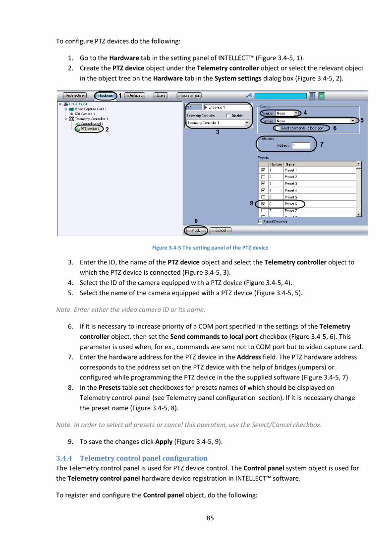
85
To configure PTZ devices do the following:
1. Go to the Hardware tab in the setting panel of INTELLECT™ (Figure 3.4-5, 1).
2. Create the PTZ device object under the Telemetry controller object or select the relevant object
in the object tree on the Hardware tab in the System settings dialog box (Figure 3.4-5, 2).
Figure 3.4-5 The setting panel of the PTZ device
3. Enter the ID, the name of the PTZ device object and select the Telemetry controller object to
which the PTZ device is connected (Figure 3.4-5, 3).
4. Select the ID of the camera equipped with a PTZ device (Figure 3.4-5, 4).
5. Select the name of the camera equipped with a PTZ device (Figure 3.4-5, 5).
Note. Enter either the video camera ID or its name.
6. If it is necessary to increase priority of a COM port specified in the settings of the Telemetry
controller object, then set the Send commands to local port checkbox (Figure 3.4-5, 6). This
parameter is used when, for ex., commands are sent not to COM port but to video capture card.
7. Enter the hardware address for the PTZ device in the Address field. The PTZ hardware address
corresponds to the address set on the PTZ device with the help of bridges (jumpers) or
configured while programming the PTZ device in the the supplied software (Figure 3.4-5, 7)
8. In the Presets table set checkboxes for presets names of which should be displayed on
Telemetry control panel (see Telemetry panel configuration section). If it is necessary change
the preset name (Figure 3.4-5, 8).
Note. In order to select all presets or cancel this operation, use the Select/Cancel checkbox.
9. To save the changes click Apply (Figure 3.4-5, 9).
3.4.4 Telemetry control panel configuration
The Telemetry control panel is used for PTZ device control. The Control panel system object is used for
the Telemetry control panel hardware device registration in INTELLECT™ software.
To register and configure the Control panel object, do the following:
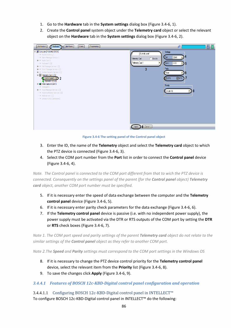
86
1. Go to the Hardware tab in the System settings dialog box (Figure 3.4-6, 1).
2. Create the Control panel system object under the Telemetry card object or select the relevant
object on the Hardware tab in the System settings dialog box (Figure 3.4-6, 2).
Figure 3.4-6 The setting panel of the Control panel object
3. Enter the ID, the name of the Telemetry object and select the Telemetry card object to which
the PTZ device is connected (Figure 3.4-6, 3).
4. Select the COM port number from the Port list in order to connect the Control panel device
(Figure 3.4-6, 4).
Note. The Control panel is connected to the COM port different from that to wich the PTZ device is
connected. Consequently on the settings panel of the parent (for the Control panel object) Telemetry
card object, another COM port number must be specified.
5. If it is necessary enter the speed of data exchange between the computer and the Telemetry
control panel device (Figure 3.4-6, 5).
6. If it is necessary enter parity check parameters for the data exchange (Figure 3.4-6, 6).
7. If the Telemetry control panel device is passive (i.e. with no independent power supply), the
power supply must be activated via the DTR or RTS outputs of the COM port by setting the DTR
or RTS check boxes (Figure 3.4-6, 7).
Note 1. The COM port speed and parity settings of the parent Telemetry card object do not relate to the
similar settings of the Control panel object as they refer to another COM port.
Note 2.The Speed and Parity settings must correspond to the COM port settings in the Windows OS
8. If it is necessary to change the PTZ device control priority for the Telemetry control panel
device, select the relevant item from the Priority list (Figure 3.4-6, 8).
9. To save the changes click Apply (Figure 3.4-6, 9).
3.4.4.1 Features of BOSCH 12c-KBD-Digital control panel configuration and operation
3.4.4.1.1 Configuring BOSCH 12c-KBD-Digital control panel in INTELLECT™
To configure BOSCH 12c-KBD-Digital control panel in INTELLECT™ do the following:
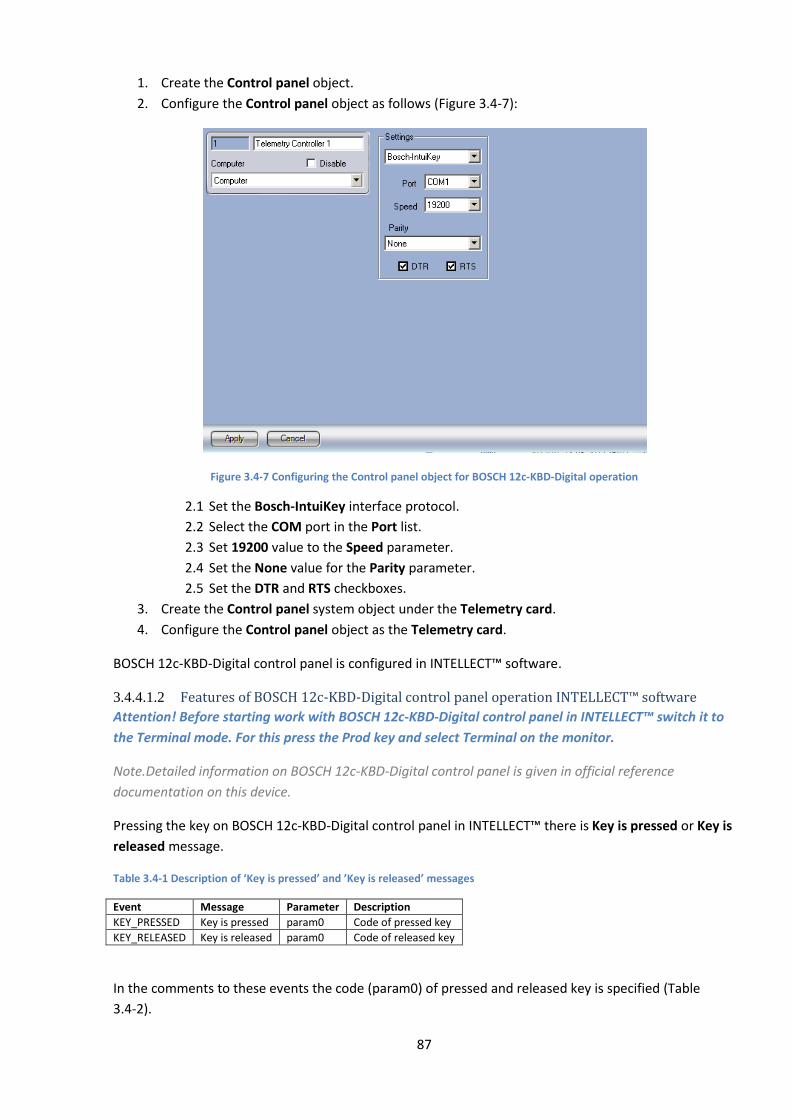
87
1. Create the Control panel object.
2. Configure the Control panel object as follows (Figure 3.4-7):
Figure 3.4-7 Configuring the Control panel object for BOSCH 12c-KBD-Digital operation
2.1 Set the Bosch-IntuiKey interface protocol.
2.2 Select the COM port in the Port list.
2.3 Set 19200 value to the Speed parameter.
2.4 Set the None value for the Parity parameter.
2.5 Set the DTR and RTS checkboxes.
3. Create the Control panel system object under the Telemetry card.
4. Configure the Control panel object as the Telemetry card.
BOSCH 12c-KBD-Digital control panel is configured in INTELLECT™ software.
3.4.4.1.2 Features of BOSCH 12c-KBD-Digital control panel operation INTELLECT™ software
Attention! Before starting work with BOSCH 12c-KBD-Digital control panel in INTELLECT™ switch it to
the Terminal mode. For this press the Prod key and select Terminal on the monitor.
Note.Detailed information on BOSCH 12c-KBD-Digital control panel is given in official reference
documentation on this device.
Pressing the key on BOSCH 12c-KBD-Digital control panel in INTELLECT™ there is Key is pressed or Key is
released message.
Table 3.4-1 Description of ‘Key is pressed’ and ’Key is released’ messages
Event Message Parameter Description
KEY_PRESSED Key is pressed param0 Code of pressed key
KEY_RELEASED Key is released param0 Code of released key
In the comments to these events the code (param0) of pressed and released key is specified (Table
3.4-2).

88
Note. With long key pressing (more then 500 milliseconds) the Key is pressed event is repeated with 100
milliseconds interval. Releasing the key one Key is released message is received.
Table 3.4-2 Key codes of BOSCH 12c-KBD-Digital control panel
Key Key code Key Key code
SOFTKEY 1L 0x01 5 0x35
SOFTKEY 2L 0x02 6 0x36
SOFTKEY 3L 0x03 7 0x37
SOFTKEY 4L 0x04 8 0x38
SOFTKEY 5L 0x05 9 0x39
SOFTKEY 6L 0x06 MONITOR 0x20
SOFTKEY 7L 0x07 PRODUCT 0x21
SOFTKEY 1R 0x08 CLEAR 0x22
SOFTKEY 2R 0x09 IRISA 0x23
SOFTKEY 3R 0x0A IRISB 0x24
SOFTKEY 4R 0x0B ACK 0x25
SOFTKEY 5R 0x0C ENTER 0x26
SOFTKEY 6R 0x0D SHOT 0x27
SOFTKEY 7R 0x0E FOCUSA 0x28
0 0x30 FOCUSB 0x29
1 0x31 SOFTKEY 4L + SOFTKEY 5L + SOFTKEY 5L
0x80
2 0x32 0 + 1 0x81
3 0x33 MONITOR + CLEAR 0x82
4 0x34
The following special features are available for BOSCH 12c-KBD-Digital control panel:
1. Paint figure (set by Figure, Type of painting, Paint figure, original Y-coordinate, end Y-
coordinate, original X-coordinate, end X-coordinate and Screen).
2. Clear screen (set by Screen parameter).
3. Type text (set by X-coordinate, Y-coordinate, Coding, Style, Screen and Text parameters).
Note 1. Bold text is displayed only on the status display.
Note 2. These actions are described in INTELLECT™ software . Programming Guide.
3.4.4.2 Features of Axis T8310 control panel configuration and operation
3.4.4.2.1 Configuring Axis T8310 control panel in INTELLECT™
To configure Axis T8310 control panel in INTELLECT™ do the following:
1. Create the Control panel object.
2. Configure the Control panel object as follows (Figure 3.4-7):
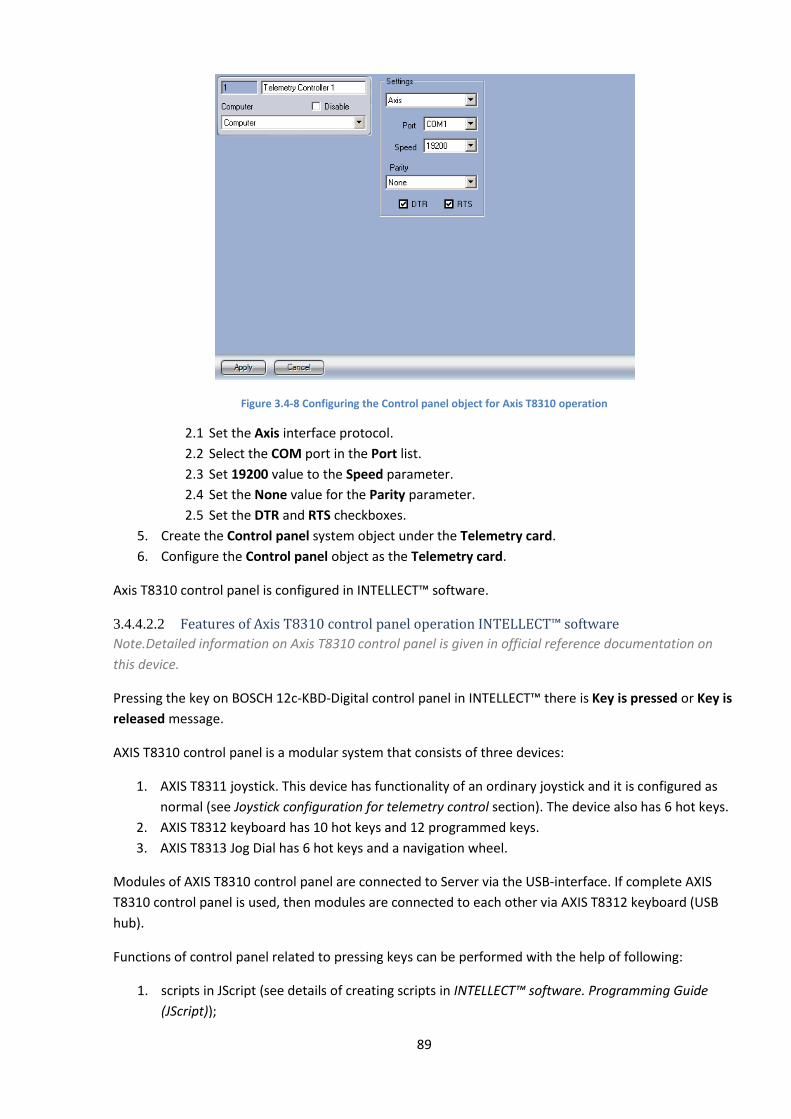
89
Figure 3.4-8 Configuring the Control panel object for Axis T8310 operation
2.1 Set the Axis interface protocol.
2.2 Select the COM port in the Port list.
2.3 Set 19200 value to the Speed parameter.
2.4 Set the None value for the Parity parameter.
2.5 Set the DTR and RTS checkboxes.
5. Create the Control panel system object under the Telemetry card.
6. Configure the Control panel object as the Telemetry card.
Axis T8310 control panel is configured in INTELLECT™ software.
3.4.4.2.2 Features of Axis T8310 control panel operation INTELLECT™ software
Note.Detailed information on Axis T8310 control panel is given in official reference documentation on
this device.
Pressing the key on BOSCH 12c-KBD-Digital control panel in INTELLECT™ there is Key is pressed or Key is
released message.
AXIS T8310 control panel is a modular system that consists of three devices:
1. AXIS T8311 joystick. This device has functionality of an ordinary joystick and it is configured as
normal (see Joystick configuration for telemetry control section). The device also has 6 hot keys.
2. AXIS T8312 keyboard has 10 hot keys and 12 programmed keys.
3. AXIS T8313 Jog Dial has 6 hot keys and a navigation wheel.
Modules of AXIS T8310 control panel are connected to Server via the USB-interface. If complete AXIS
T8310 control panel is used, then modules are connected to each other via AXIS T8312 keyboard (USB
hub).
Functions of control panel related to pressing keys can be performed with the help of following:
1. scripts in JScript (see details of creating scripts in INTELLECT™ software. Programming Guide
(JScript));
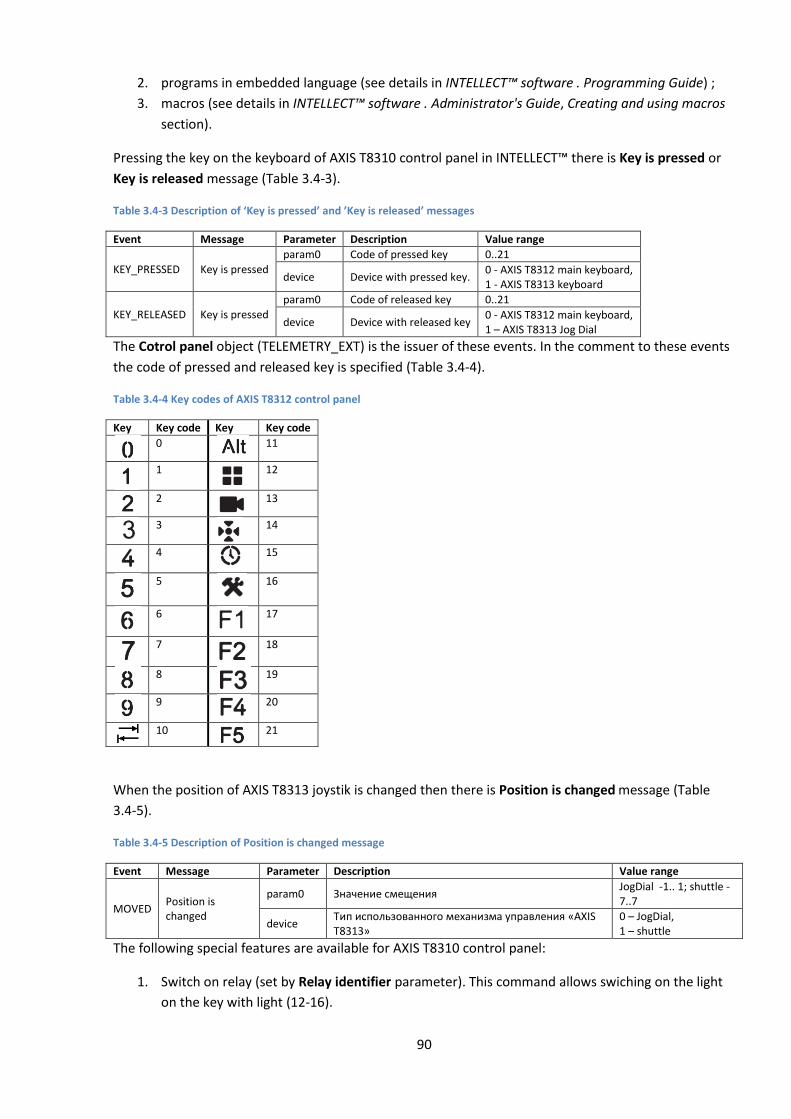
90
2. programs in embedded language (see details in INTELLECT™ software . Programming Guide) ;
3. macros (see details in INTELLECT™ software . Administrator's Guide, Creating and using macros
section).
Pressing the key on the keyboard of AXIS T8310 control panel in INTELLECT™ there is Key is pressed or
Key is released message (Table 3.4-3).
Table 3.4-3 Description of ‘Key is pressed’ and ’Key is released’ messages
Event Message Parameter Description Value range
KEY_PRESSED Key is pressed
param0 Code of pressed key 0..21
device Device with pressed key. 0 - AXIS T8312 main keyboard, 1 - AXIS T8313 keyboard
KEY_RELEASED Key is pressed
param0 Code of released key 0..21
device Device with released key 0 - AXIS T8312 main keyboard, 1 – AXIS T8313 Jog Dial
The Cotrol panel object (TELEMETRY_EXT) is the issuer of these events. In the comment to these events
the code of pressed and released key is specified (Table 3.4-4).
Table 3.4-4 Key codes of AXIS T8312 control panel
Key Key code Key Key code
0
11
1
12
2
13
3
14
4
15
5
16
6
17
7
18
8
19
9
20
10
21
When the position of AXIS T8313 joystik is changed then there is Position is changed message (Table
3.4-5).
Table 3.4-5 Description of Position is changed message
Event Message Parameter Description Value range
MOVED Position is changed
param0 Значение смещения JogDial -1.. 1; shuttle -7..7
device Тип использованного механизма управления «AXIS T8313»
0 – JogDial, 1 – shuttle
The following special features are available for AXIS T8310 control panel:
1. Switch on relay (set by Relay identifier parameter). This command allows swiching on the light
on the key with light (12-16).
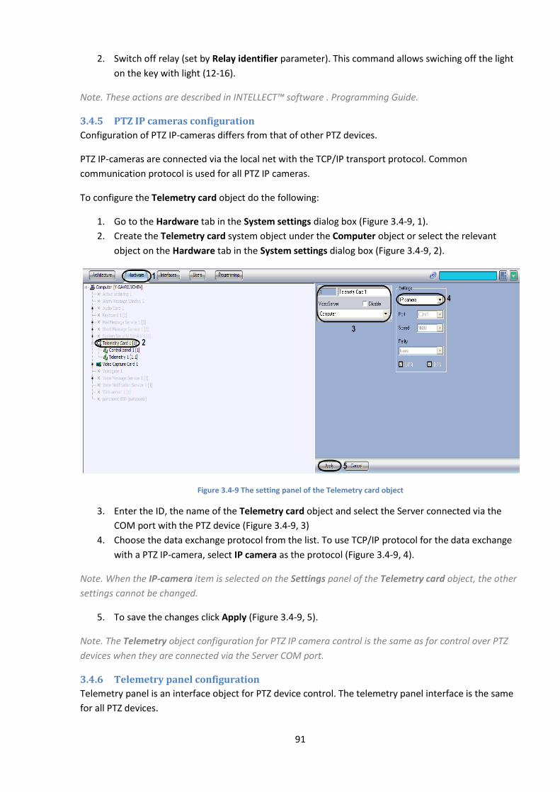
91
2. Switch off relay (set by Relay identifier parameter). This command allows swiching off the light
on the key with light (12-16).
Note. These actions are described in INTELLECT™ software . Programming Guide.
3.4.5 PTZ IP cameras configuration
Configuration of PTZ IP-cameras differs from that of other PTZ devices.
PTZ IP-cameras are connected via the local net with the TCP/IP transport protocol. Common
communication protocol is used for all PTZ IP cameras.
To configure the Telemetry card object do the following:
1. Go to the Hardware tab in the System settings dialog box (Figure 3.4-9, 1).
2. Create the Telemetry card system object under the Computer object or select the relevant
object on the Hardware tab in the System settings dialog box (Figure 3.4-9, 2).
Figure 3.4-9 The setting panel of the Telemetry card object
3. Enter the ID, the name of the Telemetry card object and select the Server connected via the
COM port with the PTZ device (Figure 3.4-9, 3)
4. Choose the data exchange protocol from the list. To use TCP/IP protocol for the data exchange
with a PTZ IP-camera, select IP camera as the protocol (Figure 3.4-9, 4).
Note. When the IP-camera item is selected on the Settings panel of the Telemetry card object, the other
settings cannot be changed.
5. To save the changes click Apply (Figure 3.4-9, 5).
Note. The Telemetry object configuration for PTZ IP camera control is the same as for control over PTZ
devices when they are connected via the Server COM port.
3.4.6 Telemetry panel configuration
Telemetry panel is an interface object for PTZ device control. The telemetry panel interface is the same
for all PTZ devices.

92
To create and configure the Telemetry panel, do the following:
1. Go to the Interfaces tab in the System settings dialog box (Figure 3.4-10, 1).
2. Create the Telemetry panel object under the Monitor object or select the relevant object on the
Interfaces tab in the System settings dialog box (Figure 3.4-10, 2).
Figure 3.4-10 The Telemetry panel configuration
3. Enter the ID, the name of the Telemetry card object and select the Screen object under which
the Telemetry card object is created (Figure 3.4-10, 3).
4. Change the X and Y coordinates of the telemetry panel position on the screen in the relevant
fields. The X and Y values correspond to the screen coordinates of the top left corner of the
telemetry panel, and are expressed as a percentage of the horizontal and vertical screen sizes
correspondingly (Figure 3.4-10, 4).
5. Enter the measures of the Telemetry panel interface object: the W (window width) and H
(window height). Measures are expressed as a percentage of the horizontal and vertical screen
sizes correspondingly (Figure 3.4-10, 5).
Note. The < button (Figure 3.4-10, 6) is used for automatic input of the current object coordinates
specified by the user.
6. By default, the telemetry panel can be dragged over the screen. To fix the telemetry panel
position, set the Allow window’s displacement checkbox unchecked (Figure 3.4-10, 7).
7. By default, the telemetry panel is opaque. To display interface objects on the same screen with
the telemetry panel, set the Transparent checkbox (Figure 3.4-10, 8).
8. If it is necessary to change the PTZ control priority via the Telemetry panel, select the relevant
item from the Priority list (Figure 3.4-10, 9).
9. By default, the Operator is allowed to save the presets of PTZ device (presets of the camera
position). To save presets, use the digital buttons on the Presets panel. To forbid the Operator
to save the presets, set the Allow set presets checkbox unchecked (Figure 3.4-10, 10).
10. Set the Allow hot key checkbox if it is necessary to control PTZ device via the keyboard (Figure
3.4-10, 11).
11. Move the names of the cameras, equipped with PTZ devices, to the Selected cameras list. These
cameras will be controlled by the Telemetry panel object. You can move the selected cameras
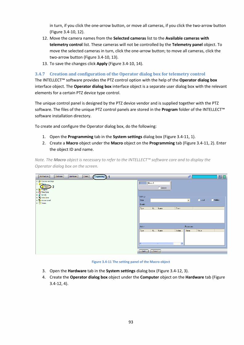
93
in turn, if you click the one-arrow button, or move all cameras, if you click the two-arrow button
(Figure 3.4-10, 12).
12. Move the camera names from the Selected cameras list to the Available cameras with
telemetry control list. These cameras will not be controlled by the Telemetry panel object. To
move the selected cameras in turn, click the one-arrow button; to move all cameras, click the
two-arrow button (Figure 3.4-10, 13).
13. To save the changes click Apply (Figure 3.4-10, 14).
3.4.7 Creation and configuration of the Operator dialog box for telemetry control
The INTELLECT™ software provides the PTZ control option with the help of the Operator dialog box
interface object. The Operator dialog box interface object is a separate user dialog box with the relevant
elements for a certain PTZ device type control.
The unique control panel is designed by the PTZ device vendor and is supplied together with the PTZ
software. The files of the unique PTZ control panels are stored in the Program folder of the INTELLECT™
software installation directory.
To create and configure the Operator dialog box, do the following:
1. Open the Programming tab in the System settings dialog box (Figure 3.4-11, 1).
2. Create a Macro object under the Macro object on the Programming tab (Figure 3.4-11, 2). Enter
the object ID and name.
Note. The Macro object is necessary to refer to the INTELLECT™ software core and to display the
Operator dialog box on the screen.
Figure 3.4-11 The setting panel of the Macro object
3. Open the Hardware tab in the System settings dialog box (Figure 3.4-12, 3).
4. Create the Operator dialog box object under the Computer object on the Hardware tab (Figure
3.4-12, 4).
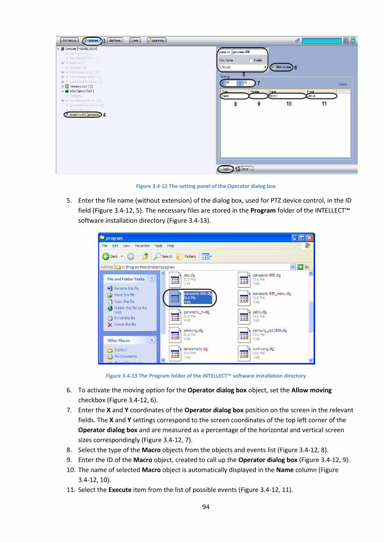
94
Figure 3.4-12 The setting panel of the Operator dialog box
5. Enter the file name (without extension) of the dialog box, used for PTZ device control, in the ID
field (Figure 3.4-12, 5). The necessary files are stored in the Program folder of the INTELLECT™
software installation directory (Figure 3.4-13).
Figure 3.4-13 The Program folder of the INTELLECT™ software installation directory
6. To activate the moving option for the Operator dialog box object, set the Allow moving
checkbox (Figure 3.4-12, 6).
7. Enter the X and Y coordinates of the Operator dialog box position on the screen in the relevant
fields. The X and Y settings correspond to the screen coordinates of the top left corner of the
Operator dialog box and are measured as a percentage of the horizontal and vertical screen
sizes correspondingly (Figure 3.4-12, 7).
8. Select the type of the Macro objects from the objects and events list (Figure 3.4-12, 8).
9. Enter the ID of the Macro object, created to call up the Operator dialog box (Figure 3.4-12, 9).
10. The name of selected Macro object is automatically displayed in the Name column (Figure
3.4-12, 10).
11. Select the Execute item from the list of possible events (Figure 3.4-12, 11).
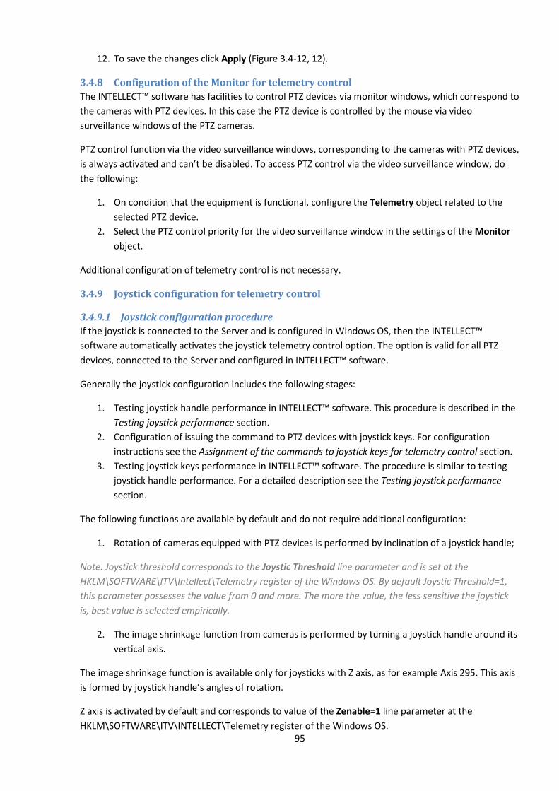
95
12. To save the changes click Apply (Figure 3.4-12, 12).
3.4.8 Configuration of the Monitor for telemetry control
The INTELLECT™ software has facilities to control PTZ devices via monitor windows, which correspond to
the cameras with PTZ devices. In this case the PTZ device is controlled by the mouse via video
surveillance windows of the PTZ cameras.
PTZ control function via the video surveillance windows, corresponding to the cameras with PTZ devices,
is always activated and can’t be disabled. To access PTZ control via the video surveillance window, do
the following:
1. On condition that the equipment is functional, configure the Telemetry object related to the
selected PTZ device.
2. Select the PTZ control priority for the video surveillance window in the settings of the Monitor
object.
Additional configuration of telemetry control is not necessary.
3.4.9 Joystick configuration for telemetry control
3.4.9.1 Joystick configuration procedure
If the joystick is connected to the Server and is configured in Windows OS, then the INTELLECT™
software automatically activates the joystick telemetry control option. The option is valid for all PTZ
devices, connected to the Server and configured in INTELLECT™ software.
Generally the joystick configuration includes the following stages:
1. Testing joystick handle performance in INTELLECT™ software. This procedure is described in the
Testing joystick performance section.
2. Configuration of issuing the command to PTZ devices with joystick keys. For configuration
instructions see the Assignment of the commands to joystick keys for telemetry control section.
3. Testing joystick keys performance in INTELLECT™ software. The procedure is similar to testing
joystick handle performance. For a detailed description see the Testing joystick performance
section.
The following functions are available by default and do not require additional configuration:
1. Rotation of cameras equipped with PTZ devices is performed by inclination of a joystick handle;
Note. Joystick threshold corresponds to the Joystic Threshold line parameter and is set at the
HKLM\SOFTWARE\ITV\Intellect\Telemetry register of the Windows OS. By default Joystiс Threshold=1,
this parameter possesses the value from 0 and more. The more the value, the less sensitive the joystick
is, best value is selected empirically.
2. The image shrinkage function from cameras is performed by turning a joystick handle around its
vertical axis.
The image shrinkage function is available only for joysticks with Z axis, as for example Axis 295. This axis
is formed by joystick handle’s angles of rotation.
Z axis is activated by default and corresponds to value of the Zenable=1 line parameter at the
HKLM\SOFTWARE\ITV\INTELLECT\Telemetry register of the Windows OS.
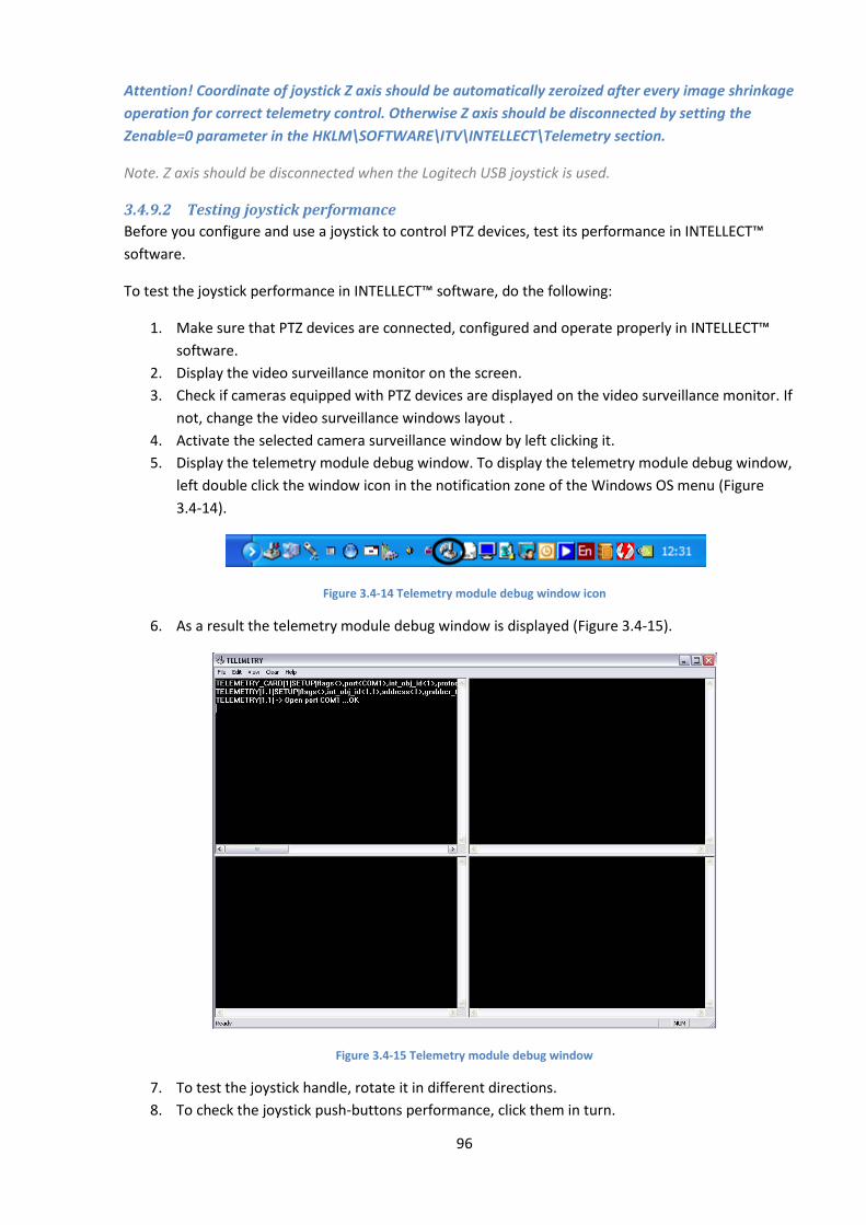
96
Attention! Coordinate of joystick Z axis should be automatically zeroized after every image shrinkage
operation for correct telemetry control. Otherwise Z axis should be disconnected by setting the
Zenable=0 parameter in the HKLM\SOFTWARE\ITV\INTELLECT\Telemetry section.
Note. Z axis should be disconnected when the Logitech USB joystick is used.
3.4.9.2 Testing joystick performance
Before you configure and use a joystick to control PTZ devices, test its performance in INTELLECT™
software.
To test the joystick performance in INTELLECT™ software, do the following:
1. Make sure that PTZ devices are connected, configured and operate properly in INTELLECT™
software.
2. Display the video surveillance monitor on the screen.
3. Check if cameras equipped with PTZ devices are displayed on the video surveillance monitor. If
not, change the video surveillance windows layout .
4. Activate the selected camera surveillance window by left clicking it.
5. Display the telemetry module debug window. To display the telemetry module debug window,
left double click the window icon in the notification zone of the Windows OS menu (Figure
3.4-14).
Figure 3.4-14 Telemetry module debug window icon
6. As a result the telemetry module debug window is displayed (Figure 3.4-15).
Figure 3.4-15 Telemetry module debug window
7. To test the joystick handle, rotate it in different directions.
8. To check the joystick push-buttons performance, click them in turn.
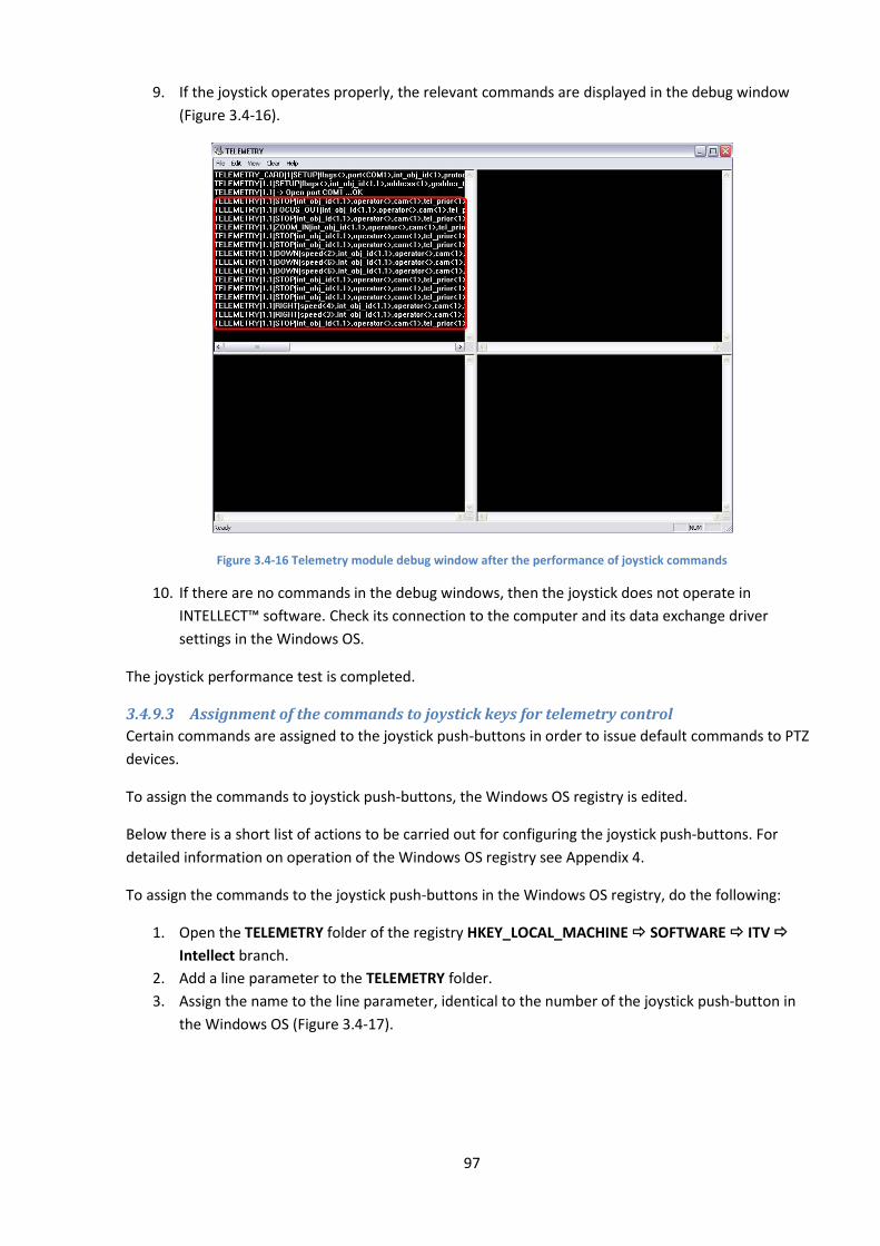
97
9. If the joystick operates properly, the relevant commands are displayed in the debug window
(Figure 3.4-16).
Figure 3.4-16 Telemetry module debug window after the performance of joystick commands
10. If there are no commands in the debug windows, then the joystick does not operate in
INTELLECT™ software. Check its connection to the computer and its data exchange driver
settings in the Windows OS.
The joystick performance test is completed.
3.4.9.3 Assignment of the commands to joystick keys for telemetry control
Certain commands are assigned to the joystick push-buttons in order to issue default commands to PTZ
devices.
To assign the commands to joystick push-buttons, the Windows OS registry is edited.
Below there is a short list of actions to be carried out for configuring the joystick push-buttons. For
detailed information on operation of the Windows OS registry see Appendix 4.
To assign the commands to the joystick push-buttons in the Windows OS registry, do the following:
1. Open the TELEMETRY folder of the registry HKEY_LOCAL_MACHINE SOFTWARE ITV
Intellect branch.
2. Add a line parameter to the TELEMETRY folder.
3. Assign the name to the line parameter, identical to the number of the joystick push-button in
the Windows OS (Figure 3.4-17).
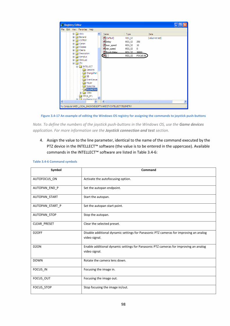
98
Figure 3.4-17 An example of editing the Windows OS registry for assigning the commands to joystick push-buttons
Note. To define the numbers of the joystick push-buttons in the Windows OS, use the Game devices
application. For more information see the Joystick connection and test section.
4. Assign the value to the line parameter, identical to the name of the command executed by the
PTZ device in the INTELLECT™ software (the value is to be entered in the uppercase). Available
commands in the INTELLECT™ software are listed in Table 3.4-6:
Table 3.4-6 Command symbols
Symbol Command
AUTOFOCUS_ON Activate the autofocusing option.
AUTOPAN_END_P Set the autopan endpoint.
AUTOPAN_START Start the autopan.
AUTOPAN_START_P Set the autopan start point.
AUTOPAN_STOP Stop the autopan.
CLEAR_PRESET Clear the selected preset.
D2OFF Disable additional dynamic settings for Panasonic PTZ cameras for improving an analog
video signal.
D2ON Enable additional dynamic settings for Panasonic PTZ cameras for improving an analog
video signal.
DOWN Rotate the camera lens down.
FOCUS_IN Focusing the image in.
FOCUS_OUT Focusing the image out.
FOCUS_STOP Stop focusing the image in/out.
99
Symbol Command
GO_PRESET.N Rotate the video camera to the position set in N preset.
HOME Rotate the video camera to the initial (home) position.
IRIS_CLOSE Close the iris diaphragm.
IRIS_OPEN Open the iris diaphragm.
IRIS_STOP Stop the iris diaphragm.
LEFT Rotate the camera lens left.
LEFT_DOWN Rotate the camera lens left and down.
LEFT_UP Rotate the camera lens Повернуть объleft and up.
PATROL_LEARN Start the programming procedure of patrolling by learning the video camera behavior.
PATROL_PLAY Start patrolling.
PATROL_STOP Stop patrolling.
RIGHT Rotate the camera lens right.
RIGHT_DOWN Rotate the camera lens right and down.
RIGHT_UP Rotate the camera lens right and up.
SET_PRESET Save the current position of the video camera in the selected preset.
STOP Stop the the camera lens rotation.
UP Rotate the camera lens up.
Repeat steps 2-4 for each joystick push-button to which the command is assigned.
Note. Some PTZ devices do not react to commands by the joystick push-buttons used for video camera
rotation. In this case you can rotate a video camera with a joystick handle.
Configuration of the joystick push-buttons is completed.

100
4 Conclusion Please send your comments or requests concerning this Guide to the AxxonSoft Training and
documentation development division at ([email protected]).
Axxon Soft Inc., Beryozovaya alleya, building 5, section 5a, Moscow, Russia, 127273 Tel/fax: (495) 775-29-29
www.axxonsoft.com
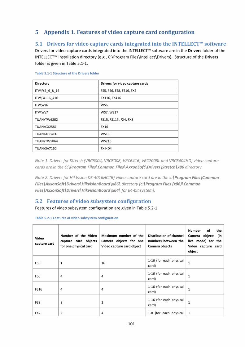
101
5 Appendix 1. Features of video capture card configuration
5.1 Drivers for video capture cards integrated into the INTELLECT™ software Drivers for video capture cards integrated into the INTELLECT™ software are in the Drivers folder of the
INTELLECT™ installation directory (e.g., C:\Program Files\Intellect\Drivers). Structure of the Drivers
folder is given in Table 5.1-1.
Table 5.1-1 Structure of the Drivers folder
Directory Drivers for video capture cards
ITV\Fs5_6_8_16 FS5, FS6, FS8, FS16, FX2
ITV\FX116_416 FX116, FX416
ITV\Ws6 WS6
ITV\Ws7 WS7, WS17
TUAN\TW6802 FS15, FS115, FX4, FX8
TUAN\CX2581 FX16
TUAN\AH8400 WS16
TUAN\TW5864 WS216
TUAN\SA7160 FX HD4
Note 1. Drivers for Stretch (VRC6004, VRC6008, VRC6416, VRC7008L and VRC6404HD) video capture
cards are in the C:\Program Files\Common Files\AxxonSoft\Drivers\Stretch\x86 directory.
Note 2. Drivers for HikVision DS-4016HCI(R) video capture card are in the c:\Program Files\Common
Files\AxxonSoft\Drivers\HikvisionBoard\x86\ directory (c:\Program Files (x86)\Common
Files\AxxonSoft\Drivers\HikvisionBoard\x64\ for 64-bit system).
5.2 Features of video subsystem configuration Features of video subsystem configuration are given in Table 5.2-1.
Table 5.2-1 Features of video subsystem configuration
Video
capture card
Number of the Video
capture card objects
for one physical card
Maximum number of the
Camera objects for one
Video capture card object
Distribution of channel
numbers between the
Camera objects
Number of the
Camera objects (in
live mode) for the
Video capture card
object
FS5 1 16 1-16 (for each physical
card) 1
FS6 4 4 1-16 (for each physical
card) 1
FS16 4 4 1-16 (for each physical
card) 1
FS8 8 2 1-16 (for each physical
card) 1
FX2 2 4 1-8 (for each physical 1
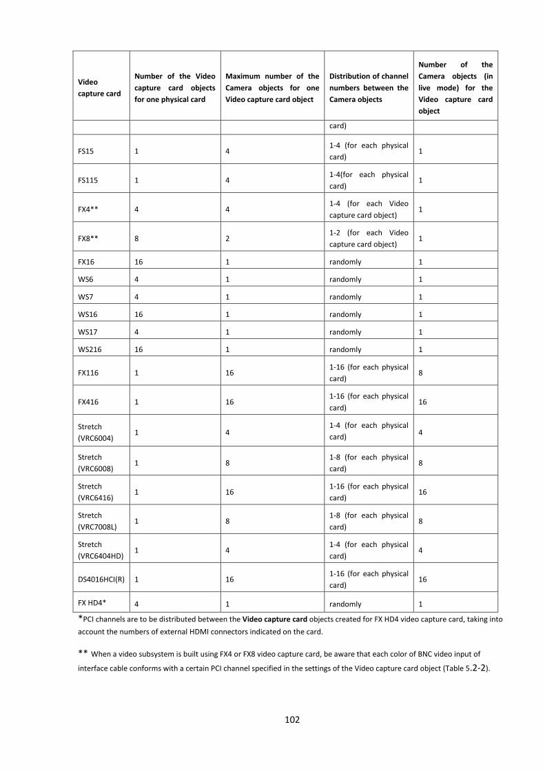
102
Video
capture card
Number of the Video
capture card objects
for one physical card
Maximum number of the
Camera objects for one
Video capture card object
Distribution of channel
numbers between the
Camera objects
Number of the
Camera objects (in
live mode) for the
Video capture card
object
card)
FS15 1 4 1-4 (for each physical
card) 1
FS115 1 4 1-4(for each physical
card) 1
FX4** 4 4 1-4 (for each Video
capture card object) 1
FX8** 8 2 1-2 (for each Video
capture card object) 1
FX16 16 1 randomly 1
WS6 4 1 randomly 1
WS7 4 1 randomly 1
WS16 16 1 randomly 1
WS17 4 1 randomly 1
WS216 16 1 randomly 1
FX116 1 16 1-16 (for each physical
card) 8
FX416 1 16 1-16 (for each physical
card) 16
Stretch
(VRC6004) 1 4
1-4 (for each physical
card) 4
Stretch
(VRC6008) 1 8
1-8 (for each physical
card) 8
Stretch
(VRC6416) 1 16
1-16 (for each physical
card) 16
Stretch
(VRC7008L) 1 8
1-8 (for each physical
card) 8
Stretch
(VRC6404HD) 1 4
1-4 (for each physical
card) 4
DS4016HCI(R) 1 16 1-16 (for each physical
card) 16
FX HD4* 4 1 randomly 1
*PCI channels are to be distributed between the Video capture card objects created for FX HD4 video capture card, taking into
account the numbers of external HDMI connectors indicated on the card.
** When a video subsystem is built using FX4 or FX8 video capture card, be aware that each color of BNC video input of
interface cable conforms with a certain PCI channel specified in the settings of the Video capture card object (Table 5.2-2).
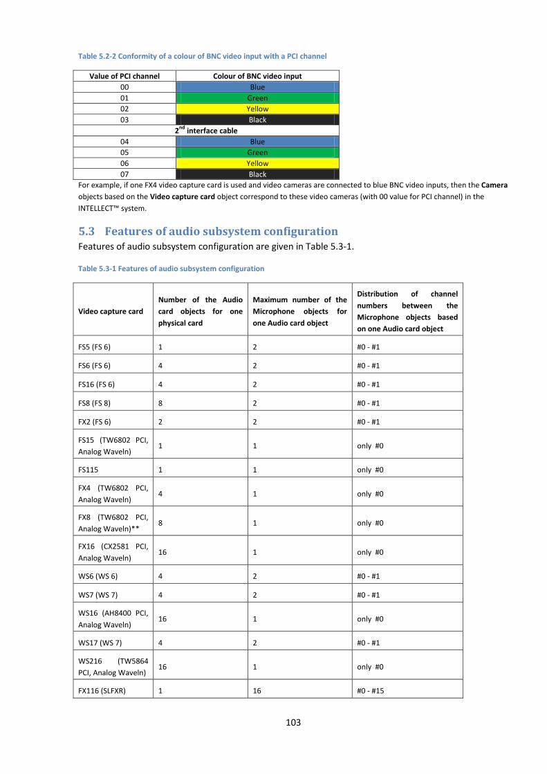
103
Table 5.2-2 Conformity of a colour of BNC video input with a PCI channel
Value of PCI channel Colour of BNC video input
00 Blue
01 Green
02 Yellow
03 Black
2nd
interface cable
04 Blue
05 Green
06 Yellow
07 Black
For example, if one FX4 video capture card is used and video cameras are connected to blue BNC video inputs, then the Camera
objects based on the Video capture card object correspond to these video cameras (with 00 value for PCI channel) in the
INTELLECT™ system.
5.3 Features of audio subsystem configuration Features of audio subsystem configuration are given in Table 5.3-1.
Table 5.3-1 Features of audio subsystem configuration
Video capture card
Number of the Audio
card objects for one
physical card
Maximum number of the
Microphone objects for
one Audio card object
Distribution of channel
numbers between the
Microphone objects based
on one Audio card object
FS5 (FS 6) 1 2 #0 - #1
FS6 (FS 6) 4 2 #0 - #1
FS16 (FS 6) 4 2 #0 - #1
FS8 (FS 8) 8 2 #0 - #1
FX2 (FS 6) 2 2 #0 - #1
FS15 (TW6802 PCI,
Analog Waveln) 1 1 only #0
FS115 1 1 only #0
FX4 (TW6802 PCI,
Analog Waveln) 4 1 only #0
FX8 (TW6802 PCI,
Analog Waveln)** 8 1 only #0
FX16 (CX2581 PCI,
Analog Waveln) 16 1 only #0
WS6 (WS 6) 4 2 #0 - #1
WS7 (WS 7) 4 2 #0 - #1
WS16 (AH8400 PCI,
Analog Waveln) 16 1 only #0
WS17 (WS 7) 4 2 #0 - #1
WS216 (TW5864
PCI, Analog Waveln) 16 1 only #0
FX116 (SLFXR) 1 16 #0 - #15
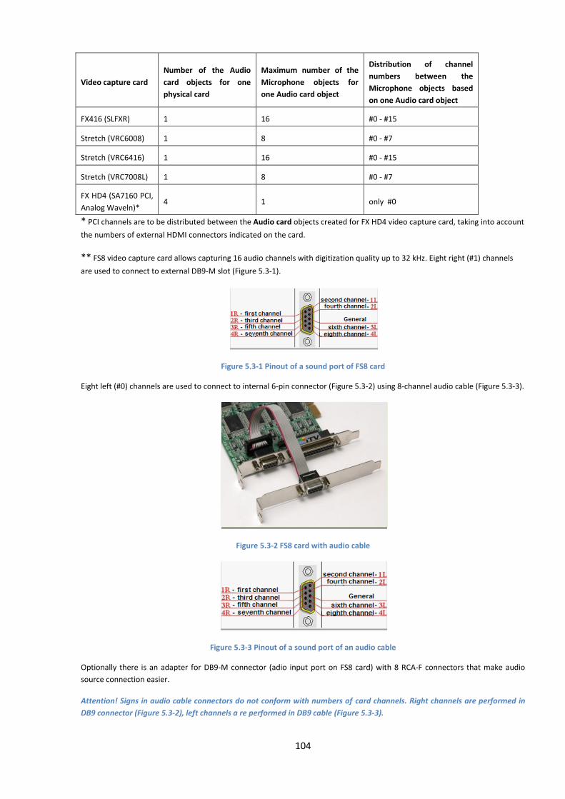
104
Video capture card
Number of the Audio
card objects for one
physical card
Maximum number of the
Microphone objects for
one Audio card object
Distribution of channel
numbers between the
Microphone objects based
on one Audio card object
FX416 (SLFXR) 1 16 #0 - #15
Stretch (VRC6008) 1 8 #0 - #7
Stretch (VRC6416) 1 16 #0 - #15
Stretch (VRC7008L) 1 8 #0 - #7
FX HD4 (SA7160 PCI,
Analog Waveln)* 4 1 only #0
* PCI channels are to be distributed between the Audio card objects created for FX HD4 video capture card, taking into account
the numbers of external HDMI connectors indicated on the card.
** FS8 video capture card allows capturing 16 audio channels with digitization quality up to 32 kHz. Eight right (#1) channels
are used to connect to external DB9-M slot (Figure 5.3-1).
Figure 5.3-1 Pinout of a sound port of FS8 card
Eight left (#0) channels are used to connect to internal 6-pin connector (Figure 5.3-2) using 8-channel audio cable (Figure 5.3-3).
Figure 5.3-2 FS8 card with audio cable
Figure 5.3-3 Pinout of a sound port of an audio cable
Optionally there is an adapter for DB9-M connector (adio input port on FS8 card) with 8 RCA-F connectors that make audio
source connection easier.
Attention! Signs in audio cable connectors do not conform with numbers of card channels. Right channels are performed in
DB9 connector (Figure 5.3-2), left channels a re performed in DB9 cable (Figure 5.3-3).
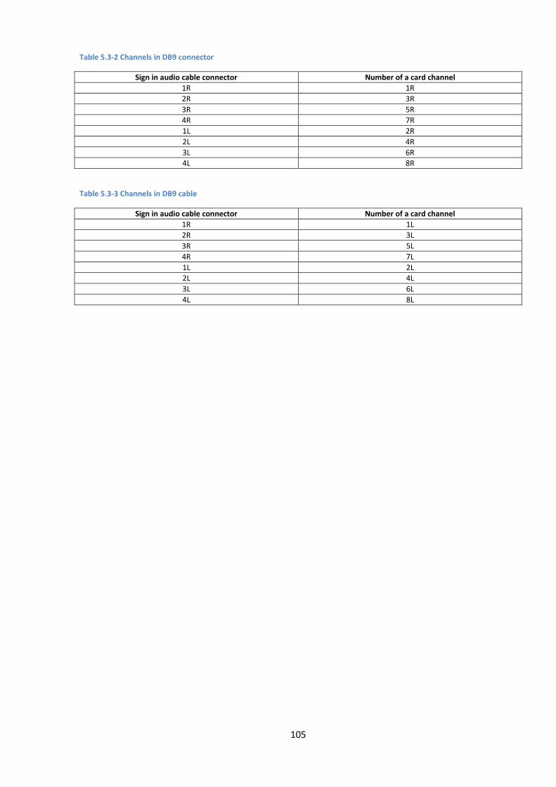
105
Table 5.3-2 Channels in DB9 connector
Sign in audio cable connector Number of a card channel
1R 1R
2R 3R
3R 5R
4R 7R
1L 2R
2L 4R
3L 6R
4L 8R
Table 5.3-3 Channels in DB9 cable
Sign in audio cable connector Number of a card channel
1R 1L
2R 3L
3R 5L
4R 7L
1L 2L
2L 4L
3L 6L
4L 8L
106
6 Appendix 2. IP-device configuration in the Windows OS
6.1 Configuration of IP-devices by the example of Axis camera IP-devices in Windows OS are configured with the software supplied with the network module.
To configure the IP-device in Windows OS, the following software supplied with the device is used:
1. software included into the package supplied with the network device. This software allows:
1.1. searching for the network devices connected to the local network computers.
1.2. assigning initial IP-addresses (without routing).
Note. An initial IP-address is required to enable access to the home pages of the devices installed in the
embedded Web-servers.
2. The Web-server module of the network device. This module contains home pages of all
connected network devices. The Web-server module allows the following:
2.1. configuring network devices including routing.
2.2. configuring modes of operation of the network devices with video and audio signals.
2.3. playback of the video image from the network devices in the standard Web-browser
mode.
6.1.1 Search for IP-devices
The delivery set of the network devices consists of various software including different utilities designed
to search for the network devices of the same type connected to the local network computers.
IPUtility.exe utility is used when Axis cameras are used to search for connected network cameras.
IPUtility.exe is a part of delivery set of Axis cameras and is stored in the Axis installation software
directory.
To search for Axis IP-cameras connected to the local network computers, using the IPUtility.exe utility,
do the following:
1. Select Search in the IPUtility.exe tools panel (Figure 6.1-1).

107
Figure 6.1-1 The IPUtility.exe interface window. The Search button
The search for Axis IP-cameras starts as soon as the Search button is clicked.
2. The IPUtility.exe window displays a list of Axis IP-cameras available in the local network (Figure
6.1-2).
Figure 6.1-2 Example of search result for the network Axis cameras
6.1.2 Assigning network addresses to IP devices
To ensure correct operation of the network devices within the local video surveillance system, their IP-
addresses are to be configured correctly. IP-addresses are configured using the utilities included into
the software distribution kit.
Before assigning an IP-address to the Axis network surveillance camera, do the following:
1. Make sure that the Axis network camera is connected to the mains and correctly connected to
the telecommunication network.
2. Get a unique IP-address from the Network administrator.
3. Make sure that the device displays its own MAC-address correctly. The MAC-address of Axis
cameras corresponds to the serial number of the camera.

108
Note 1.The following examples use a computer with 192.168.0.1 IP-address, whereas an Axis camera is
installed to 192.168.0.90 IP-address. The MAC-address for an Axis camera is 00408C70D7DE. The
addresses given as an example are not to be used; always consult your network administrator before
assigning an IP-address.
Note 2. Selecting an IP-address to be assigned to an IP-camera, keep in mind that the initial IP-address of
the camera connected for the first time is to correspond to the same subnetwork as the IP-address of
computer. Later on, if required, the IP-address can be modified using the Web-server of the device.
To assign an IP-address to the Axis network camera, do the following:
1. Check that the IP-address to be assigned to the Axis network camera is not used by any other
devices.
The IP-address in Windows OS is checked using the command line. To display the command line on the
monitor select the Run command in the Start menu (Figure 6.1-3).
Figure 6.1-3 The Run command selected from the Start menu
Now enter the cmd command in the Open field of the Run dialog box and click OK to confirm the entry
(Figure 6.1-4).
Figure 6.1-4 Command line window
As a result the command line is displayed on the monitor (Figure 6.1-5).
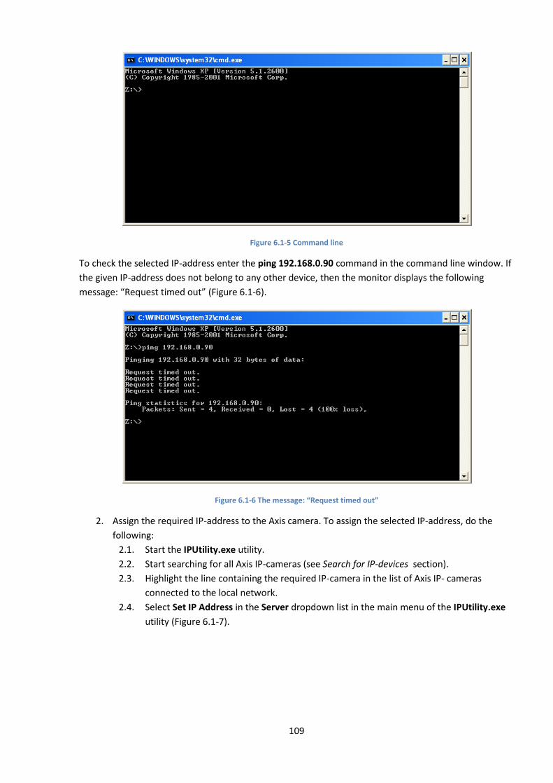
109
Figure 6.1-5 Command line
To check the selected IP-address enter the ping 192.168.0.90 command in the command line window. If
the given IP-address does not belong to any other device, then the monitor displays the following
message: “Request timed out” (Figure 6.1-6).
Figure 6.1-6 The message: “Request timed out”
2. Assign the required IP-address to the Axis camera. To assign the selected IP-address, do the
following:
2.1. Start the IPUtility.exe utility.
2.2. Start searching for all Axis IP-cameras (see Search for IP-devices section).
2.3. Highlight the line containing the required IP-camera in the list of Axis IP- cameras
connected to the local network.
2.4. Select Set IP Address in the Server dropdown list in the main menu of the IPUtility.exe
utility (Figure 6.1-7).
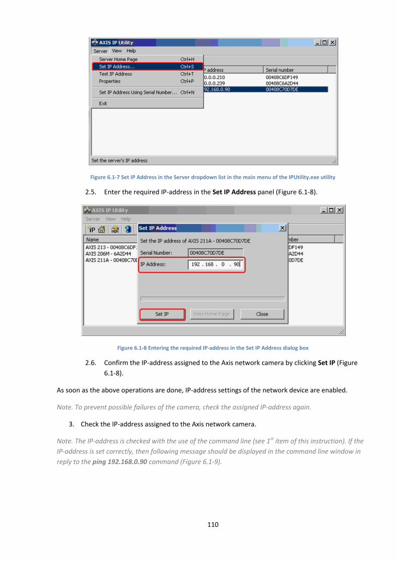
110
Figure 6.1-7 Set IP Address in the Server dropdown list in the main menu of the IPUtility.exe utility
2.5. Enter the required IP-address in the Set IP Address panel (Figure 6.1-8).
Figure 6.1-8 Entering the required IP-address in the Set IP Address dialog box
2.6. Confirm the IP-address assigned to the Axis network camera by clicking Set IP (Figure
6.1-8).
As soon as the above operations are done, IP-address settings of the network device are enabled.
Note. To prevent possible failures of the camera, check the assigned IP-address again.
3. Check the IP-address assigned to the Axis network camera.
Note. The IP-address is checked with the use of the command line (see 1st item of this instruction). If the
IP-address is set correctly, then following message should be displayed in the command line window in
reply to the ping 192.168.0.90 command (Figure 6.1-9).
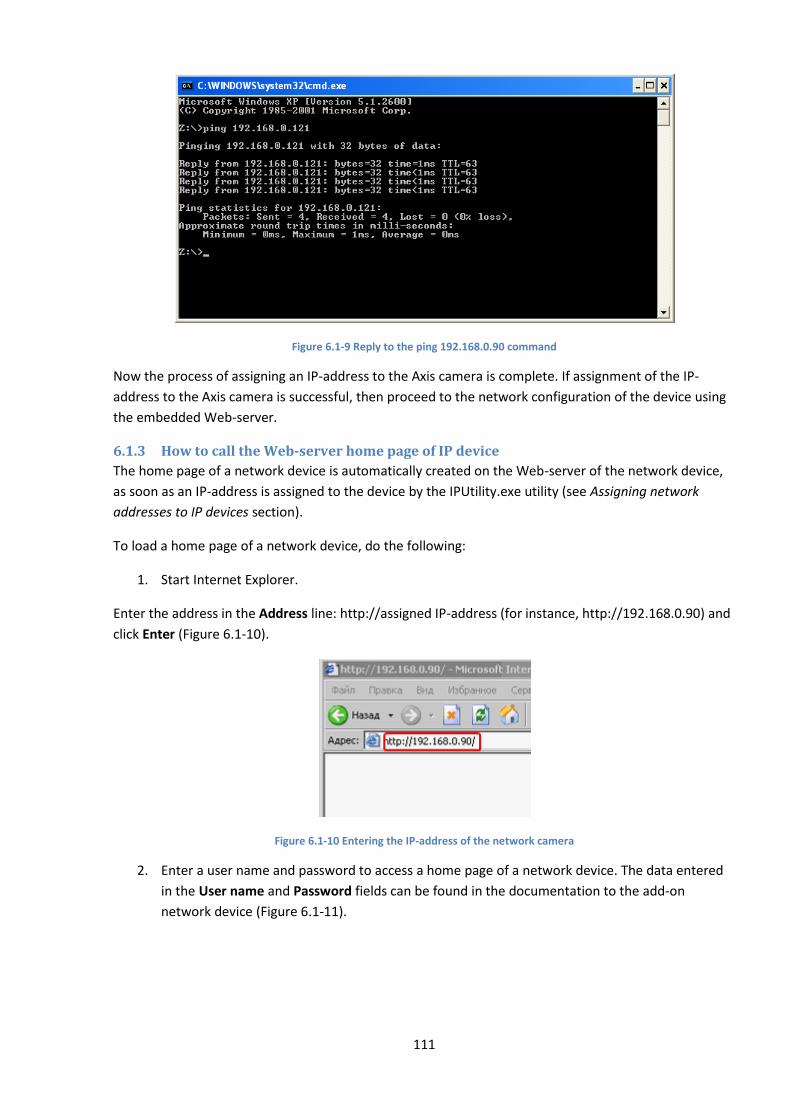
111
Figure 6.1-9 Reply to the ping 192.168.0.90 command
Now the process of assigning an IP-address to the Axis camera is complete. If assignment of the IP-
address to the Axis camera is successful, then proceed to the network configuration of the device using
the embedded Web-server.
6.1.3 How to call the Web-server home page of IP device
The home page of a network device is automatically created on the Web-server of the network device,
as soon as an IP-address is assigned to the device by the IPUtility.exe utility (see Assigning network
addresses to IP devices section).
To load a home page of a network device, do the following:
1. Start Internet Explorer.
Enter the address in the Address line: http://assigned IP-address (for instance, http://192.168.0.90) and
click Enter (Figure 6.1-10).
Figure 6.1-10 Entering the IP-address of the network camera
2. Enter a user name and password to access a home page of a network device. The data entered
in the User name and Password fields can be found in the documentation to the add-on
network device (Figure 6.1-11).
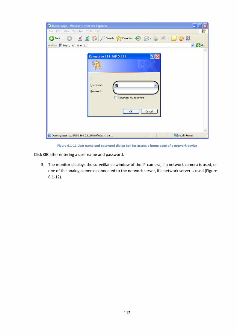
112
Figure 6.1-11 User name and password dialog box for access a home page of a network device
Click OK after entering a user name and password.
3. The monitor displays the surveillance window of the IP-camera, if a network camera is used, or
one of the analog cameras connected to the network server, if a network server is used (Figure
6.1-12).

113
Figure 6.1-12 Surveillance windows displaying an image of an IP camera or one of analog cameras connected to the network server
Note. If an IP-camera gives no image, check if the IP-address is assigned correctly (see Assigning network
addresses to IP devices section).
6.1.4 Configuration of network parameters for IP-devices using the Web-server
Network parameters of the IP-devices are configured via the embedded Web-server of the network
device.
Note. Configuration of the network parameters for IP-devices using the Web-server is a compulsory
procedure.
To configure IP-devices for operations in the local network that is either equipped or non-equipped with
the routers, do the following:
1. Start Internet Explorer.
2. Open a home page of the network device (see How to call the Web-server home page of IP
device section).
3. Open the Setup section in the Web-server feature menu of the Web browser home page (Figure
6.1-13).
Figure 6.1-13 The Setup section in the Web-server feature menu of a network device
4. Select the TCP/IP tab in the Setup section.
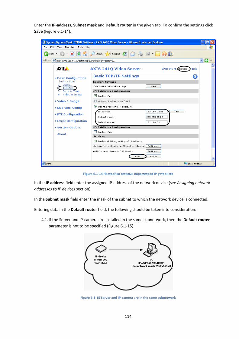
114
Enter the IP-address, Subnet mask and Default router in the given tab. To confirm the settings click
Save (Figure 6.1-14).
Figure 6.1-14 Настройка сетевых параметров IP-устройств
In the IP address field enter the assigned IP-address of the network device (see Assigning network
addresses to IP devices section).
In the Subnet mask field enter the mask of the subnet to which the network device is connected.
Entering data in the Default router field, the following should be taken into consideration:
4.1. If the Server and IP-camera are installed in the same subnetwork, then the Default router
parameter is not to be specified (Figure 6.1-15).
Figure 6.1-15 Server and IP-camera are in the same subnetwork
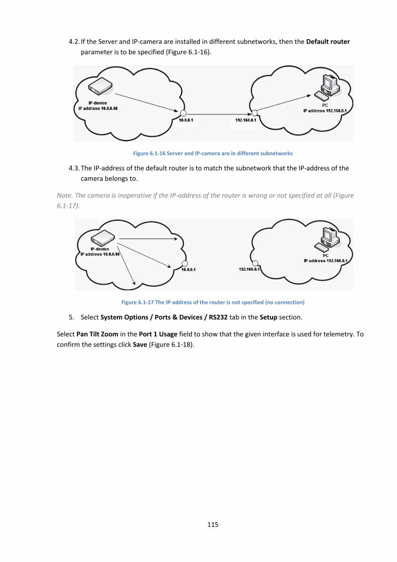
115
4.2. If the Server and IP-camera are installed in different subnetworks, then the Default router
parameter is to be specified (Figure 6.1-16).
Figure 6.1-16 Server and IP-camera are in different subnetworks
4.3. The IP-address of the default router is to match the subnetwork that the IP-address of the
camera belongs to.
Note. The camera is inoperative if the IP-address of the router is wrong or not specified at all (Figure
6.1-17).
Figure 6.1-17 The IP-address of the router is not specified (no connection)
5. Select System Options / Ports & Devices / RS232 tab in the Setup section.
Select Pan Tilt Zoom in the Port 1 Usage field to show that the given interface is used for telemetry. To
confirm the settings click Save (Figure 6.1-18).
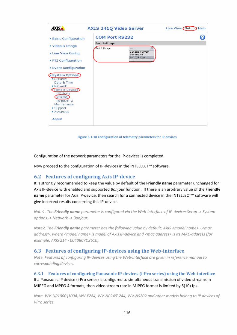
116
Figure 6.1-18 Configuration of telemetry parameters for IP-devices
Configuration of the network parameters for the IP-devices is completed.
Now proceed to the configuration of IP-devices in the INTELLECT™ software.
6.2 Features of configuring Axis IP-device It is strongly recommended to keep the value by default of the Friendly name parameter unchanged for
Axis IP-device with enabled and supported Bonjour function. If there is an arbitrary value of the Friendly
name parameter for Axis IP-device, then search for a connected device in the INTELLECT™ software will
give incorrect results concerning this IP-device.
Note1. The Friendly name parameter is configured via the Web-interface of IP-device: Setup -> System
options -> Network -> Bonjour.
Note2. The Friendly name parameter has the following value by default: AXIS <model name> - <mac
address>, where <model name> is model of Axis IP-device and <mac address> is its MAC-address (for
example, AXIS 214 - 00408C7D2610).
6.3 Features of configuring IP-devices using the Web-interface Note. Features of configuring IP-devices using the Web-interface are given in reference manual to
corresponding devices.
6.3.1 Features of configuring Panasonic IP-devices (i-Pro series) using the Web-interface
If a Panasonic IP device (i-Pro series) is configured to simultaneous transmission of video streams in
MJPEG and MPEG-4 formats, then video stream rate in MJPEG format is limited by 5(10) fps.
Note. WV-NP1000\1004, WV-F284, WV-NP240\244, WV-NS202 and other models belong to IP devices of
i-Pro series.
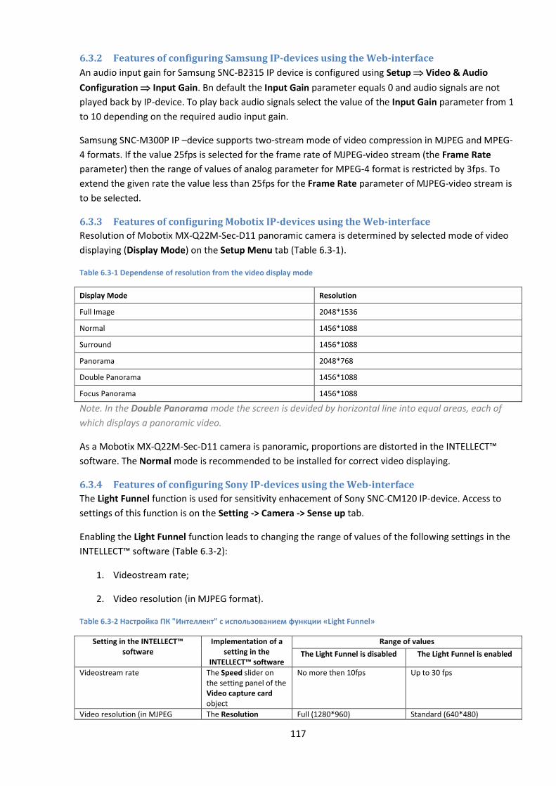
117
6.3.2 Features of configuring Samsung IP-devices using the Web-interface
An audio input gain for Samsung SNC-B2315 IP device is configured using Setup Video & Audio
Configuration Input Gain. Bn default the Input Gain parameter equals 0 and audio signals are not
played back by IP-device. To play back audio signals select the value of the Input Gain parameter from 1
to 10 depending on the required audio input gain.
Samsung SNC-M300P IP –device supports two-stream mode of video compression in MJPEG and MPEG-
4 formats. If the value 25fps is selected for the frame rate of MJPEG-video stream (the Frame Rate
parameter) then the range of values of analog parameter for MPEG-4 format is restricted by 3fps. To
extend the given rate the value less than 25fps for the Frame Rate parameter of MJPEG-video stream is
to be selected.
6.3.3 Features of configuring Mobotix IP-devices using the Web-interface
Resolution of Mobotix MX-Q22M-Sec-D11 panoramic camera is determined by selected mode of video
displaying (Display Mode) on the Setup Menu tab (Table 6.3-1).
Table 6.3-1 Dependense of resolution from the video display mode
Display Mode Resolution
Full Image 2048*1536
Normal 1456*1088
Surround 1456*1088
Panorama 2048*768
Double Panorama 1456*1088
Focus Panorama 1456*1088
Note. In the Double Panorama mode the screen is devided by horizontal line into equal areas, each of
which displays a panoramic video.
As a Mobotix MX-Q22M-Sec-D11 camera is panoramic, proportions are distorted in the INTELLECT™
software. The Normal mode is recommended to be installed for correct video displaying.
6.3.4 Features of configuring Sony IP-devices using the Web-interface
The Light Funnel function is used for sensitivity enhacement of Sony SNC-CM120 IP-device. Access to
settings of this function is on the Setting -> Camera -> Sense up tab.
Enabling the Light Funnel function leads to changing the range of values of the following settings in the
INTELLECT™ software (Table 6.3-2):
1. Videostream rate;
2. Video resolution (in MJPEG format).
Table 6.3-2 Настройка ПК "Интеллект" с использованием функции «Light Funnel»
Setting in the INTELLECT™ software
Implementation of a setting in the
INTELLECT™ software
Range of values
The Light Funnel is disabled The Light Funnel is enabled
Videostream rate The Speed slider on the setting panel of the Video capture card object
No more then 10fps Up to 30 fps
Video resolution (in MJPEG The Resolution Full (1280*960) Standard (640*480)

118
Setting in the INTELLECT™ software
Implementation of a setting in the
INTELLECT™ software
Range of values
format) dropdown list on the setting panel of the Camera object
High (960*720) Standard (640*480)
Example. If a full resolution is set with enabled Light Funnel function, then the video is displayed in a
standard resolution.
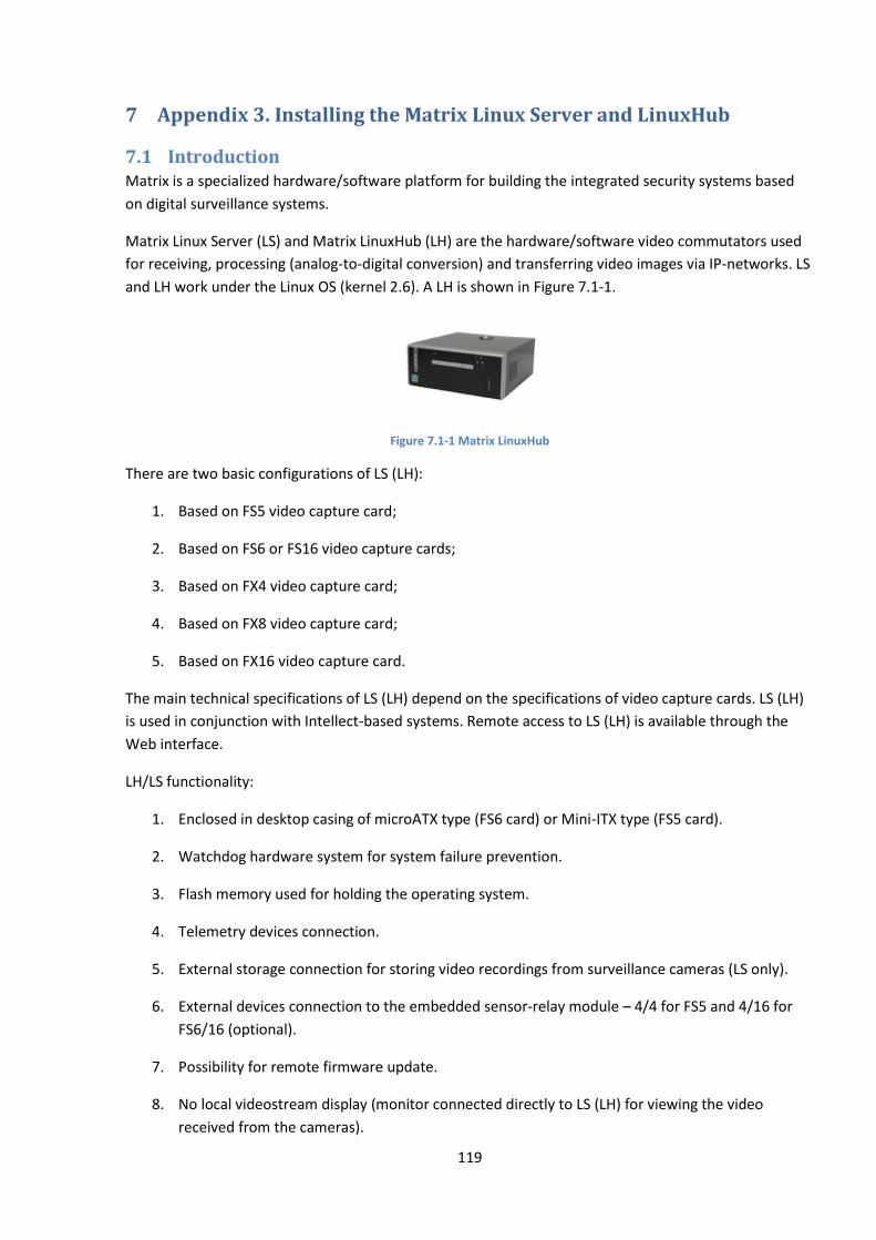
119
7 Appendix 3. Installing the Matrix Linux Server and LinuxHub
7.1 Introduction Matrix is a specialized hardware/software platform for building the integrated security systems based
on digital surveillance systems.
Matrix Linux Server (LS) and Matrix LinuxHub (LH) are the hardware/software video commutators used
for receiving, processing (analog-to-digital conversion) and transferring video images via IP-networks. LS
and LH work under the Linux OS (kernel 2.6). A LH is shown in Figure 7.1-1.
Figure 7.1-1 Matrix LinuxHub
There are two basic configurations of LS (LH):
1. Based on FS5 video capture card;
2. Based on FS6 or FS16 video capture cards;
3. Based on FX4 video capture card;
4. Based on FX8 video capture card;
5. Based on FX16 video capture card.
The main technical specifications of LS (LH) depend on the specifications of video capture cards. LS (LH)
is used in conjunction with Intellect-based systems. Remote access to LS (LH) is available through the
Web interface.
LH/LS functionality:
1. Enclosed in desktop casing of microATX type (FS6 card) or Mini-ITX type (FS5 card).
2. Watchdog hardware system for system failure prevention.
3. Flash memory used for holding the operating system.
4. Telemetry devices connection.
5. External storage connection for storing video recordings from surveillance cameras (LS only).
6. External devices connection to the embedded sensor-relay module – 4/4 for FS5 and 4/16 for
FS6/16 (optional).
7. Possibility for remote firmware update.
8. No local videostream display (monitor connected directly to LS (LH) for viewing the video
received from the cameras).
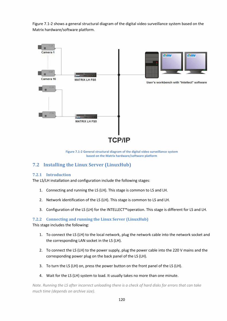
120
Figure 7.1-2 shows a general structural diagram of the digital video surveillance system based on the
Matrix hardware/software platform.
Figure 7.1-2 General structural diagram of the digital video surveillance system based on the Matrix hardware/software platform
7.2 Installing the Linux Server (LinuxHub)
7.2.1 Introduction
The LS/LH installation and configuration include the following stages:
1. Connecting and running the LS (LH). This stage is common to LS and LH.
2. Network identification of the LS (LH). This stage is common to LS and LH.
3. Configuration of the LS (LH) for the INTELLECT™operation. This stage is different for LS and LH.
7.2.2 Connecting and running the Linux Server (LinuxHub)
This stage includes the following:
1. To connect the LS (LH) to the local network, plug the network cable into the network socket and
the corresponding LAN socket in the LS (LH).
2. To connect the LS (LH) to the power supply, plug the power cable into the 220 V mains and the
corresponding power plug on the back panel of the LS (LH).
3. To turn the LS (LH) on, press the power button on the front panel of the LS (LH).
4. Wait for the LS (LH) system to load. It usually takes no more than one minute.
Note. Running the LS after incorrect unloading there is a check of hard disks for errors that can take
much time (depends on archive size).
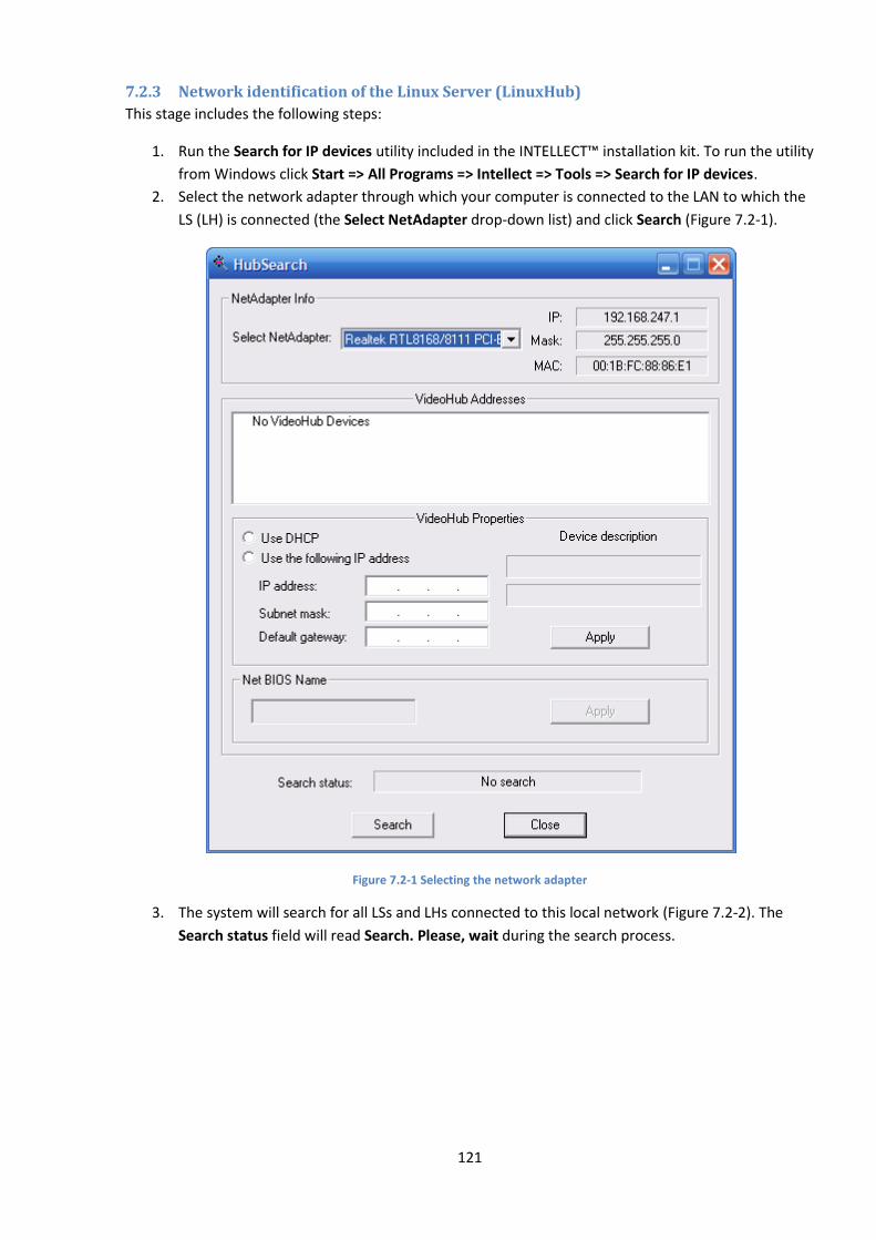
121
7.2.3 Network identification of the Linux Server (LinuxHub)
This stage includes the following steps:
1. Run the Search for IP devices utility included in the INTELLECT™ installation kit. To run the utility
from Windows click Start => All Programs => Intellect => Tools => Search for IP devices.
2. Select the network adapter through which your computer is connected to the LAN to which the
LS (LH) is connected (the Select NetAdapter drop-down list) and click Search (Figure 7.2-1).
Figure 7.2-1 Selecting the network adapter
3. The system will search for all LSs and LHs connected to this local network (Figure 7.2-2). The
Search status field will read Search. Please, wait during the search process.

122
Figure 7.2-2 Searching for LS and LH
4. After the search is completed, the Search status field will read Stop search. Find… . The found
devices will be added to the VideoHub Addresses list. Select the required LS (LH) from the list.
The VideoHub Properties field will display the information on the selected device (Figure 7.2-3).
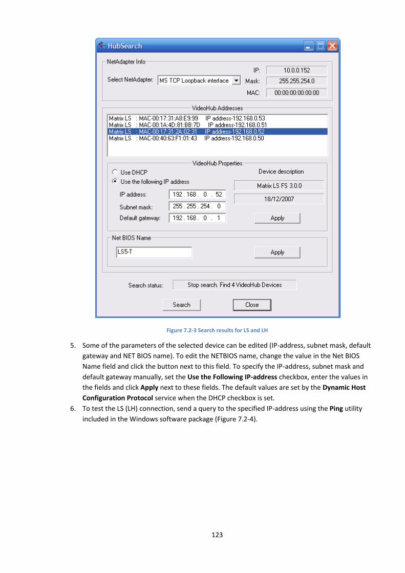
123
Figure 7.2-3 Search results for LS and LH
5. Some of the parameters of the selected device can be edited (IP-address, subnet mask, default
gateway and NET BIOS name). To edit the NETBIOS name, change the value in the Net BIOS
Name field and click the button next to this field. To specify the IP-address, subnet mask and
default gateway manually, set the Use the Following IP-address checkbox, enter the values in
the fields and click Apply next to these fields. The default values are set by the Dynamic Host
Configuration Protocol service when the DHCP checkbox is set.
6. To test the LS (LH) connection, send a query to the specified IP-address using the Ping utility
included in the Windows software package (Figure 7.2-4).

124
Figure 7.2-4 Using the Ping utility
7.2.4 Configuring the Linux Server for the INTELLECT™ operation
This stage includes the following steps:
1. Run the INTELLECT™ system. To run the system from the main Windows menu click Start All
Programs Intellect Intellect.
2. Create a new Computer object in the Hardware tab (Figure 7.2-5) and enter the NetBIOS name
(see Network identification of the Linux Server (LinuxHub) section) into the Computer name
field.
Figure 7.2-5 Creating a Computer object
Specify the IP-addresses of your computer and LS in the Architecture tab then restart the INTELLECT™
system (Figure 7.2-6, Figure 7.2-7).

125
Figure 7.2-6 Entering an LS IP-address
Figure 7.2-7 Entering a computer IP-address
3. In the Hardware tab click Reconnect in the contextual menu of the created computer object. If
the settings are correct, the created computer is displayed in the hardware list (Figure 7.2-8).
Figure 7.2-8 The connected computer is displayed in the list
Make other settings in the INTELLECT™ system. For example, to display video received from a camera
connected to the LS, create a Video Capture Card object under the Computer <NetBIOS name> object
in the tree, and configure the created camera (Figure 7.2-9, Figure 7.2-10).
Figure 7.2-9 Creating a Camera object
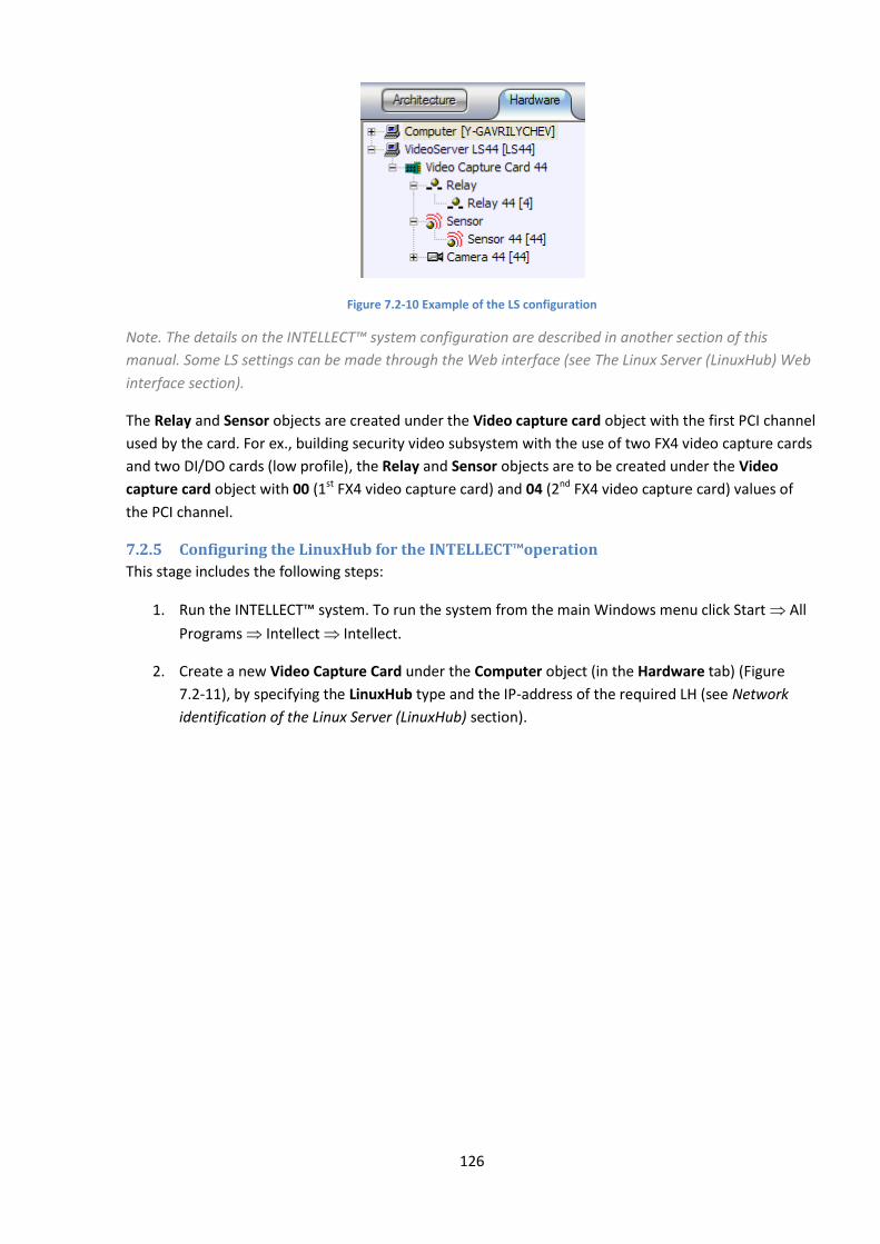
126
Figure 7.2-10 Example of the LS configuration
Note. The details on the INTELLECT™ system configuration are described in another section of this
manual. Some LS settings can be made through the Web interface (see The Linux Server (LinuxHub) Web
interface section).
The Relay and Sensor objects are created under the Video capture card object with the first PCI channel
used by the card. For ex., building security video subsystem with the use of two FX4 video capture cards
and two DI/DO cards (low profile), the Relay and Sensor objects are to be created under the Video
capture card object with 00 (1st FX4 video capture card) and 04 (2nd FX4 video capture card) values of
the PCI channel.
7.2.5 Configuring the LinuxHub for the INTELLECT™operation
This stage includes the following steps:
1. Run the INTELLECT™ system. To run the system from the main Windows menu click Start All
Programs Intellect Intellect.
2. Create a new Video Capture Card under the Computer object (in the Hardware tab) (Figure
7.2-11), by specifying the LinuxHub type and the IP-address of the required LH (see Network
identification of the Linux Server (LinuxHub) section).
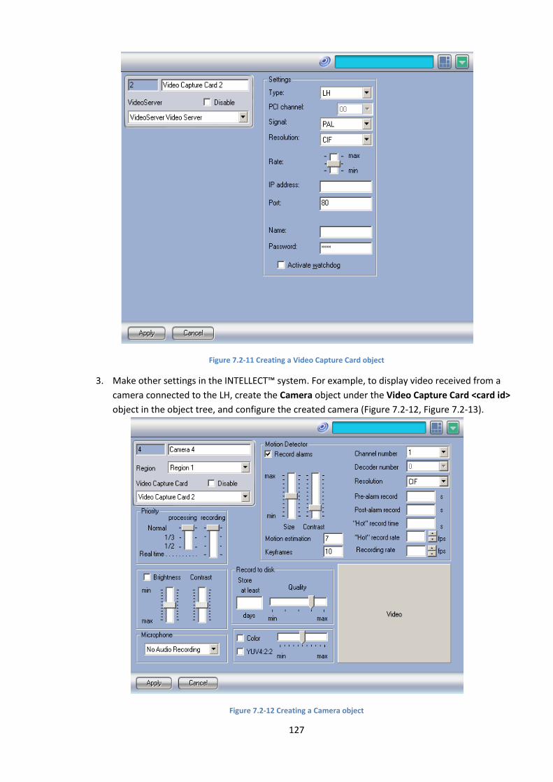
127
Figure 7.2-11 Creating a Video Capture Card object
3. Make other settings in the INTELLECT™ system. For example, to display video received from a
camera connected to the LH, create the Camera object under the Video Capture Card <card id>
object in the object tree, and configure the created camera (Figure 7.2-12, Figure 7.2-13).
Figure 7.2-12 Creating a Camera object
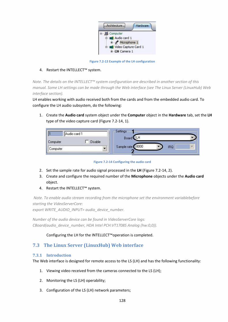
128
Figure 7.2-13 Example of the LH configuration
4. Restart the INTELLECT™ system.
Note. The details on the INTELLECT™ system configuration are described in another section of this
manual. Some LH settings can be made through the Web interface (see The Linux Server (LinuxHub) Web
interface section).
LH enables working with audio received both from the cards and from the embedded audio card. To
configure the LH audio subsystem, do the following:
1. Create the Audio card system object under the Computer object in the Hardware tab, set the LH
type of the video capture card (Figure 7.2-14, 1).
Figure 7.2-14 Configuring the audio card
2. Set the sample rate for audio signal processed in the LH (Figure 7.2-14, 2).
3. Create and configure the required number of the Microphone objects under the Audio card
object.
4. Restart the INTELLECT™ system.
Note. To enable audio stream recording from the microphone set the environment variablebefore
starting the VideoServerCore:
export WRITE_AUDIO_INPUT= audio_device_number.
Number of the audio device can be found in VideoServerCore logs:
CBoard(audio_device_number, HDA Intel PCH:VT1708S Analog (hw:0,0)).
Configuring the LH for the INTELLECT™operation is completed.
7.3 The Linux Server (LinuxHub) Web interface
7.3.1 Introduction
The Web interface is designed for remote access to the LS (LH) and has the following functionality:
1. Viewing video received from the cameras connected to the LS (LH);
2. Monitoring the LS (LH) operability;
3. Configuration of the LS (LH) network parameters;
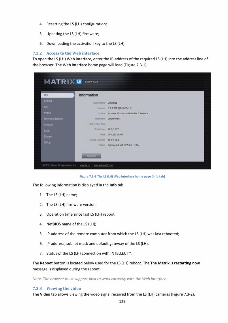
129
4. Resetting the LS (LH) configuration;
5. Updating the LS (LH) firmware;
6. Downloading the activation key to the LS (LH).
7.3.2 Access to the Web interface
To open the LS (LH) Web interface, enter the IP-address of the required LS (LH) into the address line of
the browser. The Web interface home page will load (Figure 7.3-1).
Figure 7.3-1 The LS (LH) Web interface home page (Info tab)
The following information is displayed in the Info tab:
1. The LS (LH) name;
2. The LS (LH) firmware version;
3. Operation time since last LS (LH) reboot;
4. NetBIOS name of the LS (LH);
5. IP-address of the remote computer from which the LS (LH) was last rebooted;
6. IP-address, subnet mask and default gateway of the LS (LH).
7. Status of the LS (LH) connection with INTELLECT™.
The Reboot button is located below used for the LS (LH) reboot. The The Matrix is restarting now
message is displayed during the reboot.
Note. The browser must support Java to work correctly with the Web interface.
7.3.3 Viewing the video
The Video tab allows viewing the video signal received from the LS (LH) cameras (Figure 7.3-2).

130
Figure 7.3-2 Viewing the video (Video tab)
Viewing the video received from the LS (LH) cameras in the Web interface is similar to viewing the video
through a web browser (see this manual).
7.3.4 Monitoring rays and relays status
Monitoring the status of connected rays and relays is made in the Rays and Relays tab (Figure 7.3-3).
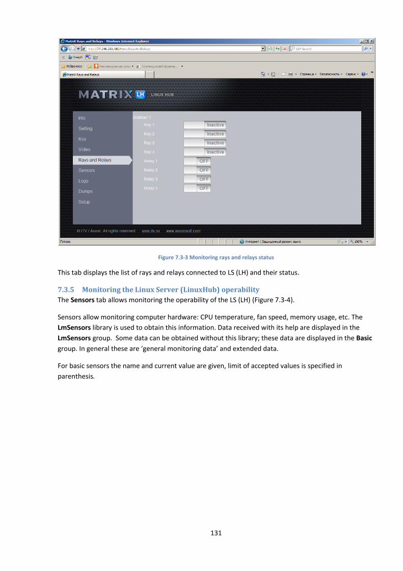
131
Figure 7.3-3 Monitoring rays and relays status
This tab displays the list of rays and relays connected to LS (LH) and their status.
7.3.5 Monitoring the Linux Server (LinuxHub) operability
The Sensors tab allows monitoring the operability of the LS (LH) (Figure 7.3-4).
Sensors allow monitoring computer hardware: CPU temperature, fan speed, memory usage, etc. The
LmSensors library is used to obtain this information. Data received with its help are displayed in the
LmSensors group. Some data can be obtained without this library; these data are displayed in the Basic
group. In general these are ‘general monitoring data’ and extended data.
For basic sensors the name and current value are given, limit of accepted values is specified in
parenthesis.
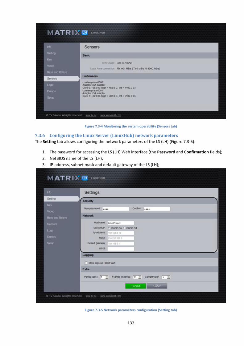
132
Figure 7.3-4 Monitoring the system operability (Sensors tab)
7.3.6 Configuring the Linux Server (LinuxHub) network parameters
The Setting tab allows configuring the network parameters of the LS (LH) (Figure 7.3-5):
1. The password for accessing the LS (LH) Web interface (the Password and Confirmation fields);
2. NetBIOS name of the LS (LH);
3. IP-address, subnet mask and default gateway of the LS (LH);
Figure 7.3-5 Network parameters configuration (Setting tab)
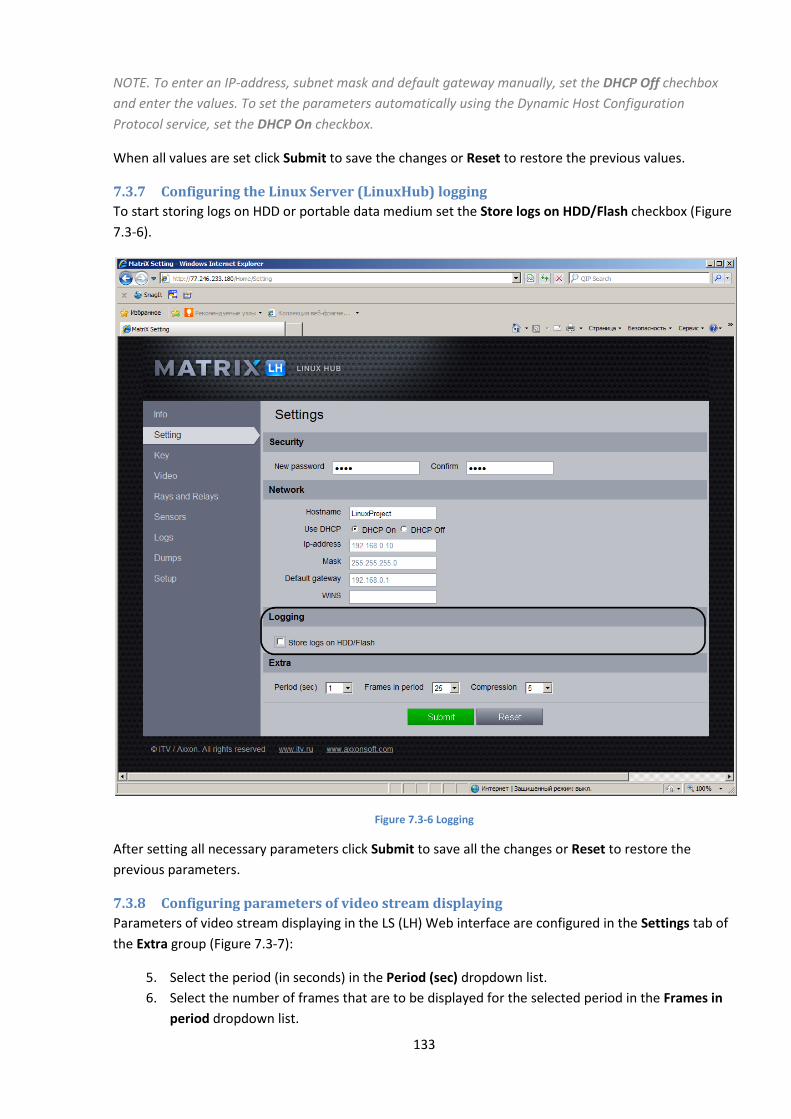
133
NOTE. To enter an IP-address, subnet mask and default gateway manually, set the DHCP Off chechbox
and enter the values. To set the parameters automatically using the Dynamic Host Configuration
Protocol service, set the DHCP On checkbox.
When all values are set click Submit to save the changes or Reset to restore the previous values.
7.3.7 Configuring the Linux Server (LinuxHub) logging
To start storing logs on HDD or portable data medium set the Store logs on HDD/Flash checkbox (Figure
7.3-6).
Figure 7.3-6 Logging
After setting all necessary parameters click Submit to save all the changes or Reset to restore the
previous parameters.
7.3.8 Configuring parameters of video stream displaying
Parameters of video stream displaying in the LS (LH) Web interface are configured in the Settings tab of
the Extra group (Figure 7.3-7):
5. Select the period (in seconds) in the Period (sec) dropdown list.
6. Select the number of frames that are to be displayed for the selected period in the Frames in
period dropdown list.
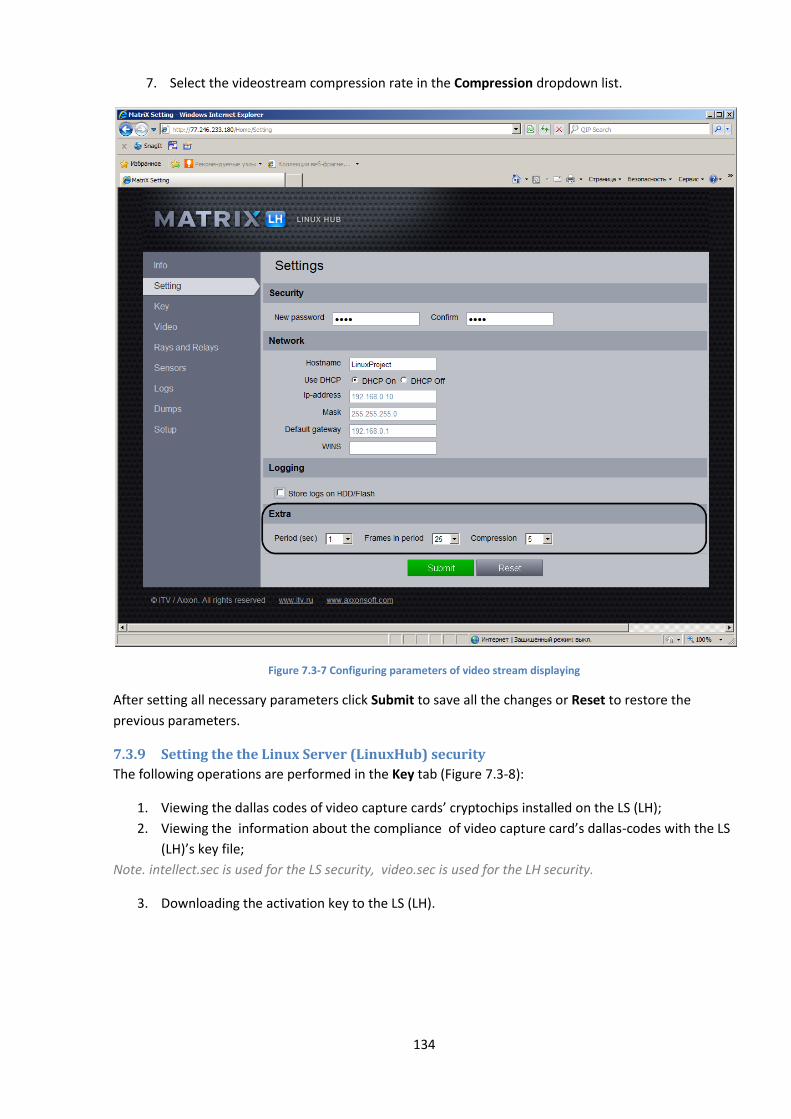
134
7. Select the videostream compression rate in the Compression dropdown list.
Figure 7.3-7 Configuring parameters of video stream displaying
After setting all necessary parameters click Submit to save all the changes or Reset to restore the
previous parameters.
7.3.9 Setting the the Linux Server (LinuxHub) security
The following operations are performed in the Key tab (Figure 7.3-8):
1. Viewing the dallas codes of video capture cards’ cryptochips installed on the LS (LH);
2. Viewing the information about the compliance of video capture card’s dallas-codes with the LS
(LH)’s key file;
Note. intellect.sec is used for the LS security, video.sec is used for the LH security.
3. Downloading the activation key to the LS (LH).
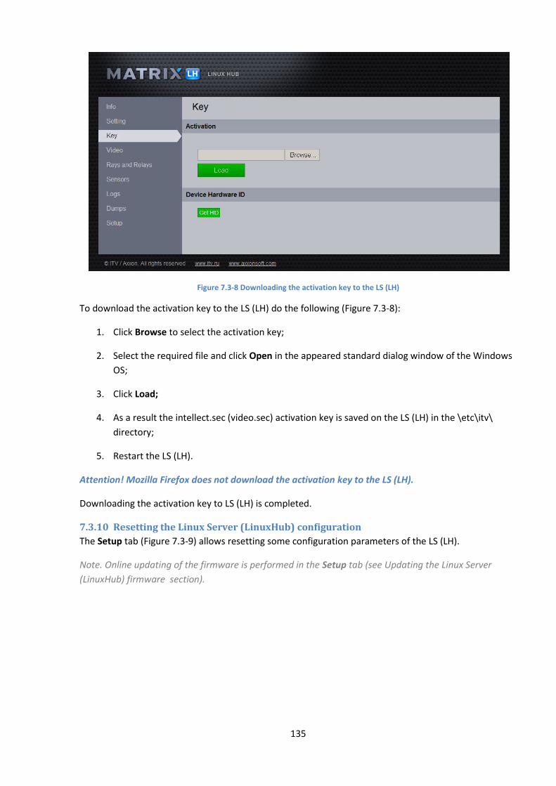
135
Figure 7.3-8 Downloading the activation key to the LS (LH)
To download the activation key to the LS (LH) do the following (Figure 7.3-8):
1. Click Browse to select the activation key;
2. Select the required file and click Open in the appeared standard dialog window of the Windows
OS;
3. Click Load;
4. As a result the intellect.sec (video.sec) activation key is saved on the LS (LH) in the \etc\itv\
directory;
5. Restart the LS (LH).
Attention! Mozilla Firefox does not download the activation key to the LS (LH).
Downloading the activation key to LS (LH) is completed.
7.3.10 Resetting the Linux Server (LinuxHub) configuration
The Setup tab (Figure 7.3-9) allows resetting some configuration parameters of the LS (LH).
Note. Online updating of the firmware is performed in the Setup tab (see Updating the Linux Server
(LinuxHub) firmware section).
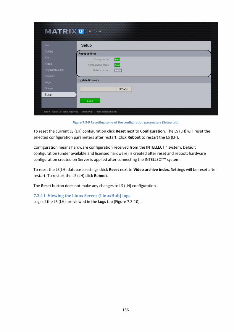
136
Figure 7.3-9 Resetting some of the configuration parameters (Setup tab)
To reset the current LS (LH) configuration click Reset next to Configuration. The LS (LH) will reset the
selected configuration parameters after restart. Click Reboot to restart the LS (LH).
Configuration means hardware configuration received from the INTELLECT™ system. Default
configuration (under available and licensed hardware) is created after reset and reboot; hardware
configuration created on Server is applied after connecting the INTELLECT™ system.
To reset the LS(LH) database settings ckick Reset next to Video archive index. Settings will be reset after
restart. To restart the LS (LH) click Reboot.
The Reset button does not make any changes to LS (LH) configuration.
7.3.11 Viewing the Linux Server (LinuxHub) logs
Logs of the LS (LH) are viewed in the Logs tab (Figure 7.3-10).
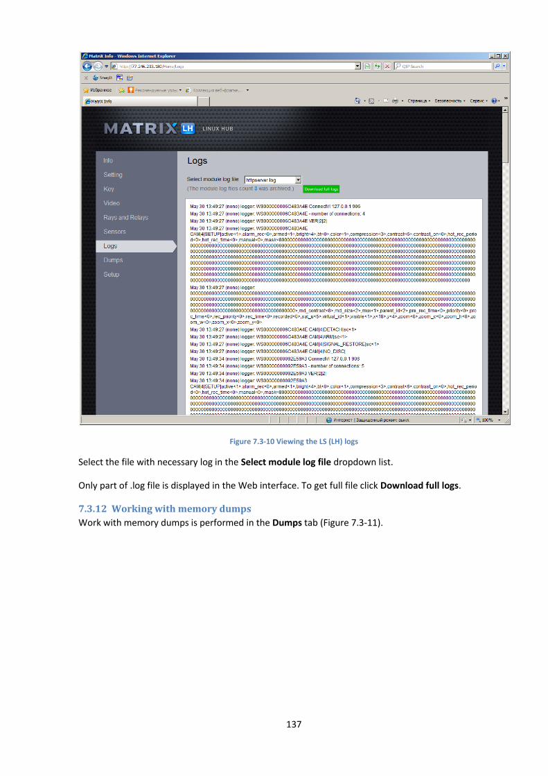
137
Figure 7.3-10 Viewing the LS (LH) logs
Select the file with necessary log in the Select module log file dropdown list.
Only part of .log file is displayed in the Web interface. To get full file click Download full logs.
7.3.12 Working with memory dumps
Work with memory dumps is performed in the Dumps tab (Figure 7.3-11).

138
Figure 7.3-11 The Dumps tab
The available dumps are displayed in the Dumps tab.
To save the dump click Download.
7.4 Updating the Linux Server (LinuxHub) firmware The LS (LH) firmware is updated via the Web interface.
Attention! Installing the LS firmware onthe LH results in incorrect LH operation.
Note. The firmware update can be carried out locally from .iso image.
To update the LS (LH) firmware via the Web interface, do the following:
1. Go to the Setup tab (Figure 7.4-1).

139
Figure 7.4-1 Updating the Linux Server (LinuxHub) firmware via the web interface
2. Click Browse to select the firmware file (Figure 7.4-1).
Note. To get the firmware file, please, contact AxxonSoft’s Help desk.
The firmware file has .iso extension.
3. Select the required firmware file and click Open in the standard dialog box.
4. Click Load (Figure 7.4-1).
5. As the result the firmware is loaded and installed on the LS (LH).
6. Wait till the process ends and then restart the LS (LH).
Updating the LS (LH) firmware via the Web interface is completed.
Note. There is no need to restore network settings and the LS(LH) activation key while updating the LS
(LH) firmware via the Web interface.
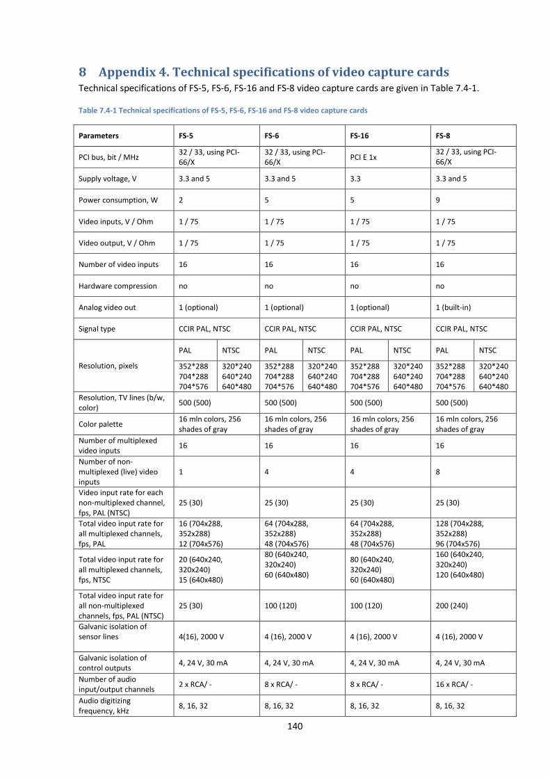
140
8 Appendix 4. Technical specifications of video capture cards Technical specifications of FS-5, FS-6, FS-16 and FS-8 video capture cards are given in Table 7.4-1.
Table 7.4-1 Technical specifications of FS-5, FS-6, FS-16 and FS-8 video capture cards
Parameters FS-5 FS-6 FS-16 FS-8
PCI bus, bit / MHz 32 / 33, using PCI-66/X
32 / 33, using PCI-66/X
PCI E 1x 32 / 33, using PCI-66/X
Supply voltage, V 3.3 and 5 3.3 and 5 3.3 3.3 and 5
Power consumption, W 2 5 5 9
Video inputs, V / Ohm 1 / 75 1 / 75 1 / 75 1 / 75
Video output, V / Ohm 1 / 75 1 / 75 1 / 75 1 / 75
Number of video inputs 16 16 16 16
Hardware compression no no no no
Analog video out 1 (optional) 1 (optional) 1 (optional) 1 (built-in)
Signal type CCIR PAL, NTSC CCIR PAL, NTSC CCIR PAL, NTSC CCIR PAL, NTSC
Resolution, pixels
PAL NTSC PAL NTSC PAL NTSC PAL NTSC
352*288 704*288 704*576
320*240 640*240 640*480
352*288 704*288 704*576
320*240 640*240 640*480
352*288 704*288 704*576
320*240 640*240 640*480
352*288 704*288 704*576
320*240 640*240 640*480
Resolution, TV lines (b/w, color)
500 (500) 500 (500) 500 (500) 500 (500)
Color palette 16 mln colors, 256 shades of gray
16 mln colors, 256 shades of gray
16 mln colors, 256 shades of gray
16 mln colors, 256 shades of gray
Number of multiplexed video inputs
16 16 16 16
Number of non-multiplexed (live) video inputs
1 4 4 8
Video input rate for each non-multiplexed channel, fps, PAL (NTSC)
25 (30) 25 (30) 25 (30) 25 (30)
Total video input rate for all multiplexed channels, fps, PAL
16 (704х288, 352х288) 12 (704х576)
64 (704х288, 352х288) 48 (704х576)
64 (704х288, 352х288) 48 (704х576)
128 (704х288, 352х288) 96 (704х576)
Total video input rate for all multiplexed channels, fps, NTSC
20 (640x240, 320x240) 15 (640x480)
80 (640x240, 320x240) 60 (640x480)
80 (640x240, 320x240) 60 (640x480)
160 (640х240, 320х240) 120 (640х480)
Total video input rate for all non-multiplexed channels, fps, PAL (NTSC)
25 (30) 100 (120) 100 (120) 200 (240)
Galvanic isolation of sensor lines
4(16), 2000 V 4 (16), 2000 V 4 (16), 2000 V 4 (16), 2000 V
Galvanic isolation of control outputs
4, 24 V, 30 mA 4, 24 V, 30 mA 4, 24 V, 30 mA 4, 24 V, 30 mA
Number of audio input/output channels
2 x RCA/ - 8 x RCA/ - 8 x RCA/ - 16 x RCA/ -
Audio digitizing frequency, kHz
8, 16, 32 8, 16, 32 8, 16, 32 8, 16, 32

141
Parameters FS-5 FS-6 FS-16 FS-8
Watchdog, hardware control of OS hanging-up
yes yes yes yes
Digital-analog conversion, bit
9 9 9 9
Technical specifications of WS-6, WS-7, WS16 and WS-17 video capture cards are given in Table 7.4-2.
Table 7.4-2 Technical specifications of WS-6, WS-7, WS16 and WS-17 video capture cards
Parameters WS-6 WS-7 WS16* WS-17
PCI bus, bit / MHz 32 / 33, using PCI-66/X
32 / 66(33) 1х 1х
Supply voltage, V 3,3 and 5 3,3 - 3,3
Power consumption, W 4 8 3,3 8
Video inputs, V / Ohm 1 / 75 1 / 75 1 / 75 1 / 75
Video output, V / Ohm no no no no
Number of video inputs 4 4 16 4
Hardware compression yes yes yes yes
Analog video out no no no no
Signal type PAL, NTSC PAL, NTSC PAL, NTSC PAL, NTSC
Resolution, pixels
PAL NTSC PAL NTSC PAL NTSC PAL NTSC
704*544 640*480 704*288 704*544
640*240 640*480
352*288 704*288 704*576
352*240 704*240 704*480
352*288 704*288 704*544
320*240 640*240 640*480
Resolution, TV lines (b/w, color)
500 (500) 500 (500) 625 (PAL)/525(NTSC) 500 (500)
Color palette 16 mln colors, 256 shades of gray
16 mln colors, 256 shades of gray
16 mln colors, 256 shades of gray
16 mln colors, 256 shades of gray
Number of multiplexed video inputs
- - - -
Number of non-multiplexed (live) video inputs
4 4 16 4
Video input rate for each non-multiplexed channel, fps, PAL (NTSC)
25 (30) 25 (30) 25 (30) 25 (30)
Total video input rate for all multiplexed channels, fps, PAL
- - - -
Total video input rate for all multiplexed channels, fps, NTSC
- - - -
Total video input rate for all non-multiplexed channels, fps, PAL (NTSC)
100 (120) 100 (120) 400(480) 100 (120)
Galvanic isolation of sensor lines
no no no no
Galvanic isolation of control outputs
no no no no
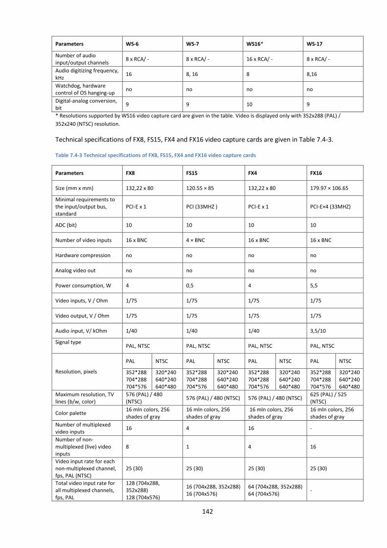
142
Parameters WS-6 WS-7 WS16* WS-17
Number of audio input/output channels
8 x RCA/ - 8 x RCA/ - 16 x RCA/ - 8 x RCA/ -
Audio digitizing frequency, kHz
16 8, 16 8 8,16
Watchdog, hardware control of OS hanging-up
no no no no
Digital-analog conversion, bit
9 9 10 9
* Resolutions supported by WS16 video capture card are given in the table. Video is displayed only with 352x288 (PAL) /
352х240 (NTSC) resolution.
Technical specifications of FX8, FS15, FX4 and FX16 video capture cards are given in Table 7.4-3.
Table 7.4-3 Technical specifications of FX8, FS15, FX4 and FX16 video capture cards
Parameters FX8 FS15 FX4 FX16
Size (mm x mm) 132,22 х 80 120.55 × 85 132,22 х 80 179.97 × 106.65
Minimal requirements to the input/output bus, standard
PCI-E x 1 PCI (33MHZ ) PCI-E x 1 PCI-E×4 (33MHZ)
ADC (bit) 10 10 10 10
Number of video inputs 16 x BNC 4 × BNC 16 x BNC 16 x BNC
Hardware compression no no no no
Analog video out no no no no
Power consumption, W 4 0,5 4 5,5
Video inputs, V / Ohm 1/75 1/75 1/75 1/75
Video output, V / Ohm 1/75 1/75 1/75 1/75
Audio input, V/ kOhm 1/40 1/40 1/40 3,5/10
Signal type PAL, NTSC PAL, NTSC PAL, NTSC PAL, NTSC
Resolution, pixels
PAL NTSC PAL NTSC PAL NTSC PAL NTSC
352*288 704*288 704*576
320*240 640*240 640*480
352*288 704*288 704*576
320*240 640*240 640*480
352*288 704*288 704*576
320*240 640*240 640*480
352*288 704*288 704*576
320*240 640*240 640*480
Maximum resolution, TV lines (b/w, color)
576 (PAL) / 480 (NTSC)
576 (PAL) / 480 (NTSC) 576 (PAL) / 480 (NTSC) 625 (PAL) / 525 (NTSC)
Color palette 16 mln colors, 256 shades of gray
16 mln colors, 256 shades of gray
16 mln colors, 256 shades of gray
16 mln colors, 256 shades of gray
Number of multiplexed video inputs
16 4 16 -
Number of non-multiplexed (live) video inputs
8 1 4 16
Video input rate for each non-multiplexed channel, fps, PAL (NTSC)
25 (30) 25 (30) 25 (30) 25 (30)
Total video input rate for all multiplexed channels, fps, PAL
128 (704х288, 352х288) 128 (704х576)
16 (704х288, 352х288) 16 (704х576)
64 (704х288, 352х288) 64 (704х576)
-
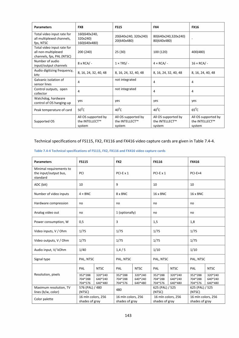
143
Parameters FX8 FS15 FX4 FX16
Total video input rate for all multiplexed channels, fps, NTSC
160(640х240, 320х240) 160(640х480)
20(640х240, 320х240) 20(640х480)
80(640х240,320х240) 80(640х480)
-
Total video input rate for all non-multiplexed channels, fps, PAL (NTSC)
200 (240) 25 (30) 100 (120) 400(480)
Number of audio input/output channels
8 х RCA/ - 1 × TRS/ - 4 × RCA/ - 16 × RCA/ -
Audio digitizing frequency, kHz
8, 16, 24, 32, 40, 48 8, 16, 24, 32, 40, 48 8, 16, 24, 32, 40, 48 8, 16, 24, 40, 48
Galvanic isolation of sensor lines
4 not integrated
4 4
Control outputs, open collector
4 not integrated
4 4
Watchdog, hardware control of OS hanging-up
yes yes yes yes
Peak temperature of card 500С 40
0С 40
0С 65
0С
Supported OS All OS supported by the INTELLECT™ system
All OS supported by the INTELLECT™ system
All OS supported by the INTELLECT™ system
All OS supported by the INTELLECT™ system
Technical specifications of FS115, FX2, FX116 and FX416 video capture cards are given in Table 7.4-4.
Table 7.4-4 Technical specifications of FS115, FX2, FX116 and FX416 video capture cards
Parameters FS115 FX2 FX116 FX416
Minimal requirements to the input/output bus, standard
PCI PCI-E x 1 PCI-E x 1 PCI-E×4
ADC (bit) 10 9 10 10
Number of video inputs 4 × BNC 8 x BNC 16 x BNC 16 x BNC
Hardware compression no no no no
Analog video out no 1 (optionally) no no
Power consumption, W 0,5 3 1,5 1,8
Video inputs, V / Ohm 1/75 1/75 1/75 1/75
Video outputs, V / Ohm 1/75 1/75 1/75 1/75
Audio input, V/ kOhm 1/40 1,4 / 5 1/10 1/10
Signal type PAL, NTSC PAL, NTSC PAL, NTSC PAL, NTSC
Resolution, pixels
PAL NTSC PAL NTSC PAL NTSC PAL NTSC
352*288 704*288 704*576
320*240 640*240 640*480
352*288 704*288 704*576
320*240 640*240 640*480
352*288 704*288 704*576
320*240 640*240 640*480
352*288 704*288 704*576
320*240 640*240 640*480
Maximum resolution, TV lines (b/w, color)
576 (PAL) / 480 (NTSC)
480 625 (PAL) / 525 (NTSC)
625 (PAL) / 525 (NTSC)
Color palette 16 mln colors, 256 shades of gray
16 mln colors, 256 shades of gray
16 mln colors, 256 shades of gray
16 mln colors, 256 shades of gray
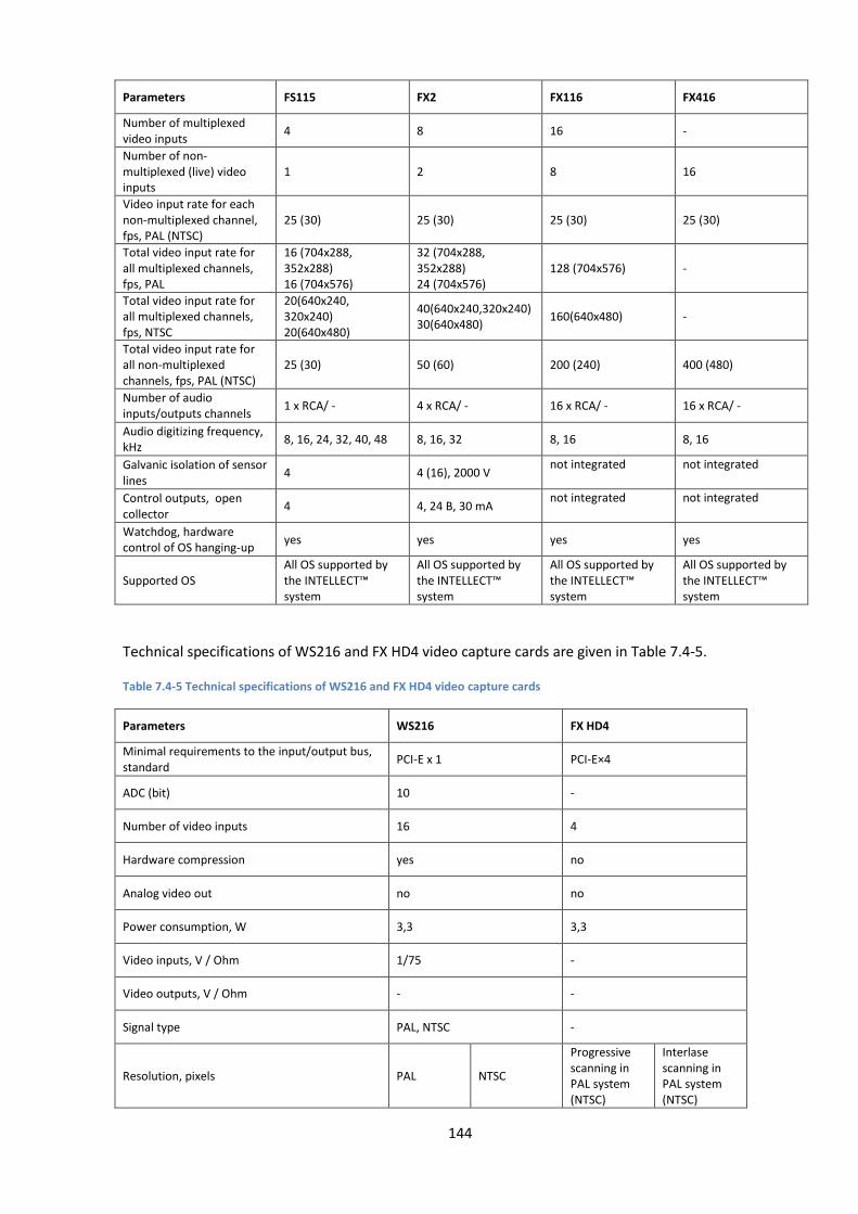
144
Parameters FS115 FX2 FX116 FX416
Number of multiplexed video inputs
4 8 16 -
Number of non-multiplexed (live) video inputs
1 2 8 16
Video input rate for each non-multiplexed channel, fps, PAL (NTSC)
25 (30) 25 (30) 25 (30) 25 (30)
Total video input rate for all multiplexed channels, fps, PAL
16 (704х288, 352х288) 16 (704х576)
32 (704х288, 352х288) 24 (704х576)
128 (704х576) -
Total video input rate for all multiplexed channels, fps, NTSC
20(640х240, 320х240) 20(640х480)
40(640х240,320х240) 30(640х480)
160(640х480) -
Total video input rate for all non-multiplexed channels, fps, PAL (NTSC)
25 (30) 50 (60) 200 (240) 400 (480)
Number of audio inputs/outputs channels
1 x RCA/ - 4 x RCA/ - 16 x RCA/ - 16 x RCA/ -
Audio digitizing frequency, kHz
8, 16, 24, 32, 40, 48 8, 16, 32 8, 16 8, 16
Galvanic isolation of sensor lines
4 4 (16), 2000 V not integrated not integrated
Control outputs, open collector
4 4, 24 В, 30 mA not integrated not integrated
Watchdog, hardware control of OS hanging-up
yes yes yes yes
Supported OS All OS supported by the INTELLECT™ system
All OS supported by the INTELLECT™ system
All OS supported by the INTELLECT™ system
All OS supported by the INTELLECT™ system
Technical specifications of WS216 and FX HD4 video capture cards are given in Table 7.4-5.
Table 7.4-5 Technical specifications of WS216 and FX HD4 video capture cards
Parameters WS216 FX HD4
Minimal requirements to the input/output bus, standard
PCI-E x 1 PCI-E×4
ADC (bit) 10 -
Number of video inputs 16 4
Hardware compression yes no
Analog video out no no
Power consumption, W 3,3 3,3
Video inputs, V / Ohm 1/75 -
Video outputs, V / Ohm - -
Signal type PAL, NTSC -
Resolution, pixels PAL NTSC
Progressive scanning in PAL system (NTSC)
Interlase scanning in PAL system (NTSC)
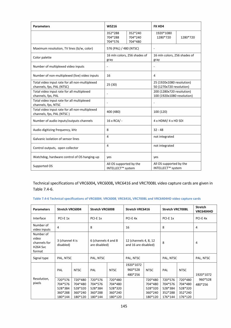
145
Parameters WS216 FX HD4
352*288 704*288 704*576
352*240 704*240 704*480
1920*1080 1280*720
1280*720
Maximum resolution, TV lines (b/w, color) 576 (PAL) / 480 (NTSC) -
Color palette 16 mln colors, 256 shades of gray
16 mln colors, 256 shades of gray
Number of multiplexed video inputs - -
Number of non-multiplexed (live) video inputs 16 4
Total video input rate for all non-multiplexed channels, fps, PAL (NTSC)
25 (30) 25 (1920х1080 resolution) 50 (1270х720 resolution)
Total video input rate for all multiplexed channels, fps, PAL
- 200 (1280х720 resolution) 100 (1920х1080 resolution)
Total video input rate for all multiplexed channels, fps, NTSC
- -
Total video input rate for all non-multiplexed channels, fps, PAL (NTSC )
400 (480) 100 (120)
Number of audio inputs/outputs channels 16 x RCA/ - 4 x HDMI/ 4 x HD SDI
Audio digitizing frequency, kHz 8 32 - 48
Galvanic isolation of sensor lines 4 not integrated
Control outputs, open collector 4 not integrated
Watchdog, hardware control of OS hanging-up yes yes
Supported OS All OS supported by the INTELLECT™ system
All OS supported by the INTELLECT™ system
Technical specifications of VRC6004, VRC6008, VRC6416 and VRC7008L video capture cards are given in
Table 7.4-6.
Table 7.4-6 Technical specifications of VRC6004, VRC6008, VRC6416, VRC7008L and VRC6404HD video capture cards
Parameters Stretch VRC6004 Stretch VRC6008 Stretch VRC6416 Stretch VRC7008L Stretch VRC6404HD
Interface PCI-E 1x PCI-E 1x PCI-E 4x PCI-E 1x PCI-E 4x
Number of video inputs
4 8 16 8 4
Number of video channels for H264 Svc format
3 (channel 4 is disabled)
6 (channels 4 and 8 are disabled)
12 (channels 4, 8, 12 and 16 are disabled)
8 4
Signal type PAL, NTSC PAL, NTSC PAL, NTSC PAL, NTSC PAL, NTSC
Resolution, pixels
PAL NTSC PAL NTSC
1920*1072
960*528
480*256
NTSC PAL NTSC
1920*1072
960*528
480*256
720*576 704*576 528*384 360*288 180*144
720*480 704*480 528*320 360*240 180*120
720*576 704*576 528*384 360*288 180*144
720*480 704*480 528*320 360*240 180*120
720*480 704*480 528*320 360*240 180*120
720*576 704*576 528*384 352*288 176*144
720*480 704*480 528*320 352*240 176*120
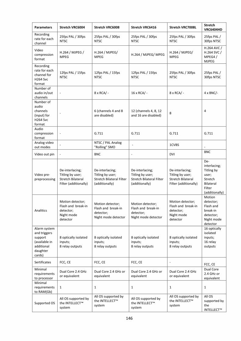
146
Parameters Stretch VRC6004 Stretch VRC6008 Stretch VRC6416 Stretch VRC7008L Stretch VRC6404HD
Recording rate for each channel
25fps PAL / 30fps NTSC
25fps PAL / 30fps NTSC
25fps PAL / 30fps NTSC
25fps PAL / 30fps NTSC
25fps PAL / 30fps NTSC
Video compression format
H.264 / MJPEG / MPEG
H.264 / MJPEG/ MPEG
H.264 / MJPEG/ MPEG H.264 / MJPEG/ MPEG
H.264 AVC / H.264 SVC / MPEG4 / MJPEG
Recording rate for each channel for H264 Svc format
12fps PAL / 15fps NTSC
12fps PAL / 15fps NTSC
12fps PAL / 15fps NTSC
25fps PAL / 30fps NTSC
25fps PAL / 30fps NTSC
Number of audio in/out channels
- 8 x RCA/ - 16 x RCA/ - 8 x RCA/ - 4 х BNC/-
Number of audio channels (input) for H264 Svc format
- 6 (channels 4 and 8 are disabled)
12 (channels 4, 8, 12 and 16 are disabled)
8
4
Audio compression format
- G.711 G.711 G.711 G.711
Analog video out modes
- NTSC / PAL Analog "Rolling" SMO
- 1CVBS -
Video out pin - BNC - DVI BNC
Video pre-preprocessing
De-interlacing; Titling by user; Stretch Bilateral Filter (additionally)
De-interlacing; Titling by user; Stretch Bilateral Filter (additionally)
De-interlacing; Titling by user; Stretch Bilateral Filter (additionally)
De-interlacing; Titling by user; Stretch Bilateral Filter (additionally)
De-interlacing; Titling by user; Stretch Bilateral Filter (additionally)
Analitics
Motion detector; Flash and break-in detector; Night mode detector
Motion detector; Flash and break-in detector; Night mode detector
Motion detector; Flash and break-in detector; Night mode detector
Motion detector; Flash and break-in detector; Night mode detector
Motion detector; Flash and break-in detector; Night mode detector
Alarm system and triggers support (available in additional daughter cards)
8 optically isolated inputs; 8 relay outputs
8 optically isolated inputs; 8 relay outputs
8 optically isolated inputs; 8 relay outputs
8 optically isolated inputs; 8 relay outputs
16 optically isolated inputs; 16 relay outputs
Sertificates FCC, CE FCC, CE FCC, CE - FCC, CE
Minimal requirements to processor
Dual Core 2.4 GHz or equivalent
Dual Core 2.4 GHz or equivalent
Dual Core 2.4 GHz or equivalent
Dual Core 2.4 GHz or equivalent
Dual Core 2.4 GHz or equivalent
Minimal requirements to RAM(Gb)
1 1 1 1 1
Supported OS All OS supported by the INTELLECT™ system
All OS supported by the INTELLECT™ system
All OS supported by the INTELLECT™ system
All OS supported by the INTELLECT™ system
All OS supported by the INTELLECT™
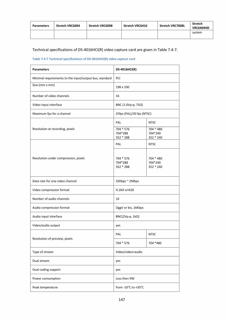
147
Parameters Stretch VRC6004 Stretch VRC6008 Stretch VRC6416 Stretch VRC7008L Stretch VRC6404HD
system
Technical specifications of DS-4016HCI(R) video capture card are given in Table 7.4-7.
Table 7.4-7 Technical specifications of DS-4016HCI(R) video capture card
Parameters DS-4016HCI(R)
Minimal requirements to the input/output bus, standard PCI
Size (mm x mm)
198 x 100
Number of video channels 16
Video input interface BNC (1.0Vp-p, 75Ω)
Maximum fps for a channel 25fps (PAL)/30 fps (NTSC)
Resolution at recording, pixels
PAL NTSC
704 * 576 704*288 352 * 288
704 * 480 704*240 352 * 240
Resolution under compression, pixels
PAL NTSC
704 * 576 704*288 352 * 288
704 * 480 704*240 352 * 240
Data rate for one video channel 32Kbps ~ 2Mbps
Video compression format H.264 orI420
Number of audio channels 16
Audio compression format OggV or bis, 16Kbps
Audio input interface BNC(2Vp-p, 1kΩ)
Video/audio output yes
Resolution of preview, pixels
PAL NTSC
704 * 576 704 *480
Type of stream Video/video+audio
Dual stream yes
Dual coding support yes
Power consumption Less then 9W
Peak temperature from -10°C to +50°C

148
Parameters DS-4016HCI(R)
Humidity 10%~90%
Supported OS All OS supported by the INTELLECT™ system
Note 1. DS-4016HCI(R) video capture card has an embedded motion detector that is not integrated at the
time of writing this manual.
Note 2. At the time of writing this manual audio is not integrated for DS-4016HCI(R) video capture card.
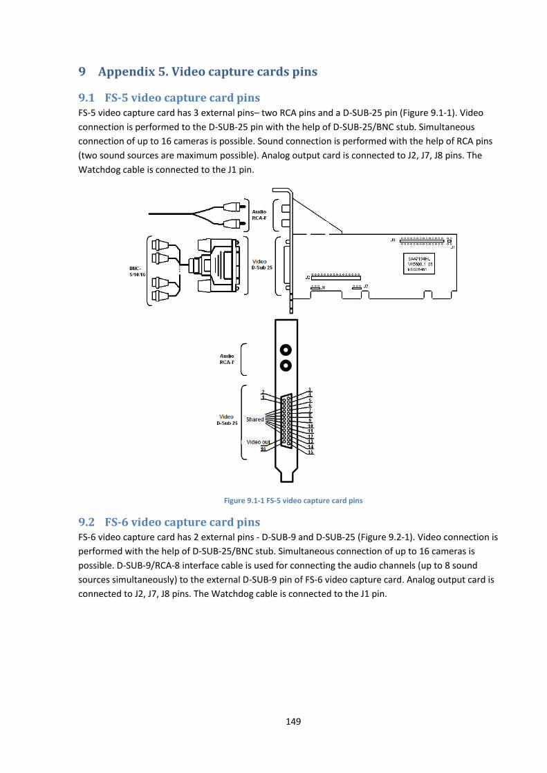
149
9 Appendix 5. Video capture cards pins
9.1 FS-5 video capture card pins FS-5 video capture card has 3 external pins– two RCA pins and a D-SUB-25 pin (Figure 9.1-1). Video
connection is performed to the D-SUB-25 pin with the help of D-SUB-25/BNC stub. Simultaneous
connection of up to 16 cameras is possible. Sound connection is performed with the help of RCA pins
(two sound sources are maximum possible). Analog output card is connected to J2, J7, J8 pins. The
Watchdog cable is connected to the J1 pin.
Figure 9.1-1 FS-5 video capture card pins
9.2 FS-6 video capture card pins FS-6 video capture card has 2 external pins - D-SUB-9 and D-SUB-25 (Figure 9.2-1). Video connection is
performed with the help of D-SUB-25/BNC stub. Simultaneous connection of up to 16 cameras is
possible. D-SUB-9/RCA-8 interface cable is used for connecting the audio channels (up to 8 sound
sources simultaneously) to the external D-SUB-9 pin of FS-6 video capture card. Analog output card is
connected to J2, J7, J8 pins. The Watchdog cable is connected to the J1 pin.
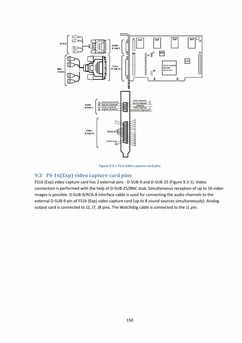
150
Figure 9.2-1 FS-6 video capture card pins
9.3 FS-16(Exp) video capture card pins FS16 (Exp) video capture card has 2 external pins - D-SUB-9 and D-SUB-25 (Figure 9.3-1). Video
connection is performed with the help of D-SUB-25/BNC stub. Simultaneous reception of up to 16 video
images is possible. D-SUB-9/RCA-8 interface cable is used for connecting the audio channels to the
external D-SUB-9 pin of FS16 (Exp) video capture card (up to 8 sound sources simultaneously). Analog
output card is connected to J2, J7, J8 pins. The Watchdog cable is connected to the J1 pin.
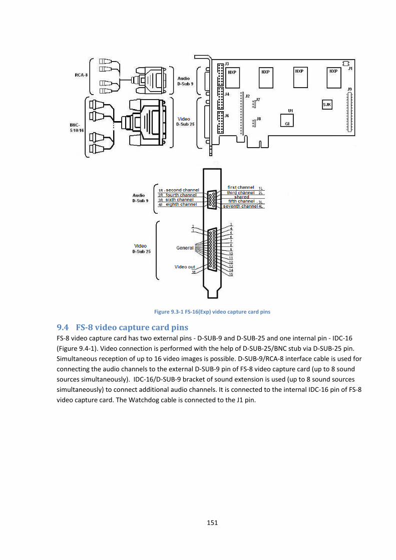
151
Figure 9.3-1 FS-16(Exp) video capture card pins
9.4 FS-8 video capture card pins FS-8 video capture card has two external pins - D-SUB-9 and D-SUB-25 and one internal pin - IDC-16
(Figure 9.4-1). Video connection is performed with the help of D-SUB-25/BNC stub via D-SUB-25 pin.
Simultaneous reception of up to 16 video images is possible. D-SUB-9/RCA-8 interface cable is used for
connecting the audio channels to the external D-SUB-9 pin of FS-8 video capture card (up to 8 sound
sources simultaneously). IDC-16/D-SUB-9 bracket of sound extension is used (up to 8 sound sources
simultaneously) to connect additional audio channels. It is connected to the internal IDC-16 pin of FS-8
video capture card. The Watchdog cable is connected to the J1 pin.
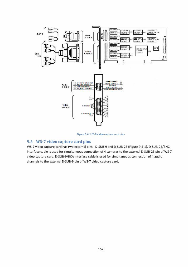
152
Figure 9.4-1 FS-8 video capture card pins
9.5 WS-7 video capture card pins WS-7 video capture card has two external pins - D-SUB-9 and D-SUB-25 (Figure 9.5-1). D-SUB-25/BNC
interface cable is used for simultaneous connection of 4 cameras to the external D-SUB-25 pin of WS-7
video capture card. D-SUB-9/RCA interface cable is used for simultaneous connection of 4 audio
channels to the external D-SUB-9 pin of WS-7 video capture card.
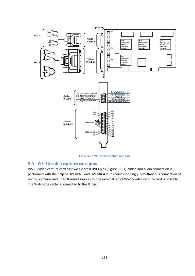
153
Figure 9.5-1 WS-7 video capture card pins
9.6 WS-16 video capture card pins WS-16 video capture card has two external DVI-I pins (Figure 9.6-1). Video and audio connection is
performed with the help of DVI-I/BNC and DVI-I/RCA stubs correspondingly. Simultaneous connection of
up to 8 cameras and up to 8 sound sources to one external pin of WS-16 video capture card is possible.
The Watchdog cable is connected to the J1 pin.

154
Figure 9.6-1 WS-16 video capture card pins
9.7 WS-17 video capture card pins WS-17 video capture card has two external pins - D-SUB-9 and D-SUB-25 (Figure 9.7-1). D-SUB-25/BNC
interface cable is used for simultaneous connection up to 4 cameras to the external D-SUB-25 pin of WS-
17 video capture card. D-SUB-9/RCA interface cable is used for simultaneous connection up to 4 audio
channels to the external D-SUB-9 pin of WS-17 video capture card.

155
Figure 9.7-1 WS-17 video capture card pins
9.8 WS216 video capture card pins WS216 video capture card has two external DVI-I pins (Figure 9.8-1). Video and audio connection is
performed with the help of DVI-I/BNC and DVI-I/RCA stubs correspondingly. Simultaneous connection of
up to 8 cameras and up to 8 sound sources to one external pin of WS216 video capture card is possible.
The Watchdog cable is connected to the J1 pin. DI/DO card is connected to the J2 pin.
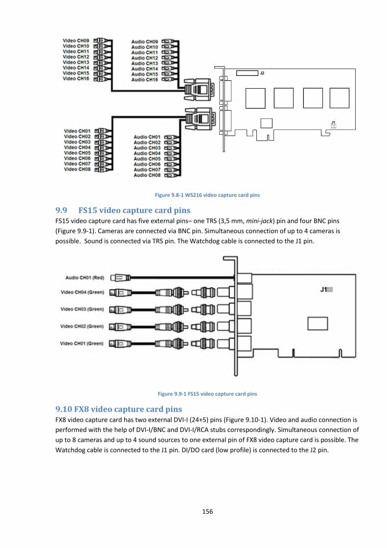
156
Figure 9.8-1 WS216 video capture card pins
9.9 FS15 video capture card pins FS15 video capture card has five external pins– one TRS (3,5 mm, mini-jack) pin and four BNC pins
(Figure 9.9-1). Cameras are connected via BNC pin. Simultaneous connection of up to 4 cameras is
possible. Sound is connected via TRS pin. The Watchdog cable is connected to the J1 pin.
Figure 9.9-1 FS15 video capture card pins
9.10 FX8 video capture card pins FX8 video capture card has two external DVI-I (24+5) pins (Figure 9.10-1). Video and audio connection is
performed with the help of DVI-I/BNC and DVI-I/RCA stubs correspondingly. Simultaneous connection of
up to 8 cameras and up to 4 sound sources to one external pin of FX8 video capture card is possible. The
Watchdog cable is connected to the J1 pin. DI/DO card (low profile) is connected to the J2 pin.
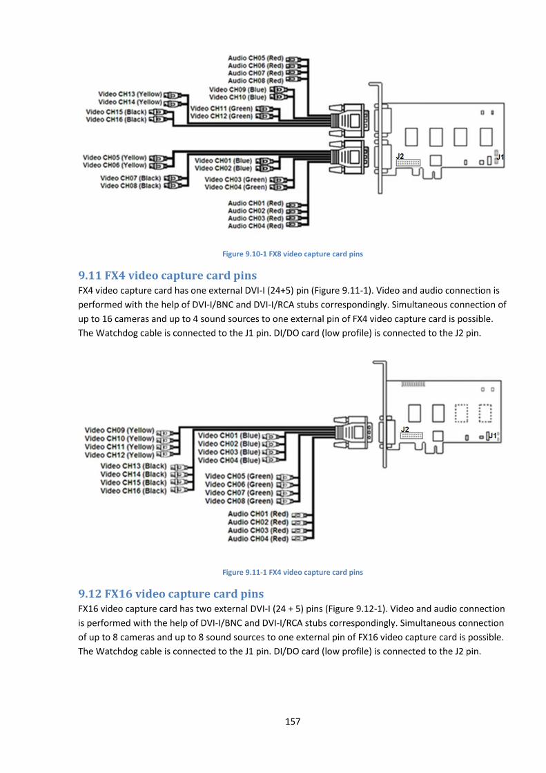
157
Figure 9.10-1 FX8 video capture card pins
9.11 FX4 video capture card pins FX4 video capture card has one external DVI-I (24+5) pin (Figure 9.11-1). Video and audio connection is
performed with the help of DVI-I/BNC and DVI-I/RCA stubs correspondingly. Simultaneous connection of
up to 16 cameras and up to 4 sound sources to one external pin of FX4 video capture card is possible.
The Watchdog cable is connected to the J1 pin. DI/DO card (low profile) is connected to the J2 pin.
Figure 9.11-1 FX4 video capture card pins
9.12 FX16 video capture card pins FX16 video capture card has two external DVI-I (24 + 5) pins (Figure 9.12-1). Video and audio connection
is performed with the help of DVI-I/BNC and DVI-I/RCA stubs correspondingly. Simultaneous connection
of up to 8 cameras and up to 8 sound sources to one external pin of FX16 video capture card is possible.
The Watchdog cable is connected to the J1 pin. DI/DO card (low profile) is connected to the J2 pin.

158
Figure 9.12-1 FX16 video capture card pins
9.13 FS115 video capture card pins FS115 video capture card has one external DVI-I pin (Figure 9.13-1). Video and audio connection is
performed with the help of DVI-I/BNC and DVI-I/RCA stubs correspondingly. Simultaneous connection of
up to 4 cameras and 1 sound source to one external pin of FS115 video capture card is possible. The
Watchdog cable is connected to the J1 pin. DI/DO card (low profile) is connected to the J2 pin.
Figure 9.13-1 FS115 video capture card pins
9.14 FX116 video capture card pins FX116 video capture card has two external pins - D-SUB 25 and D-SUB 26 (Figure 9.14-1). Simultaneous
connection of up to 8 cameras and 16 sound sources to external pins of FX116 video capture card is
possible. Video connection is performed with the help of D-SUB-25/BNC stub and audio connection is
performed with the help of D-SUB-26/RCA stub.
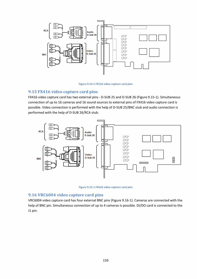
159
Figure 9.14-1 FX116 video capture card pins
9.15 FX416 video capture card pins FX416 video capture card has two external pins - D-SUB 25 and D-SUB 26 (Figure 9.15-1). Simultaneous
connection of up to 16 cameras and 16 sound sources to external pins of FX416 video capture card is
possible. Video connection is performed with the help of D-SUB 25/BNC stub and audio connection is
performed with the help of D-SUB 26/RCA stub.
Figure 9.15-1 FX416 video capture card pins
9.16 VRC6004 video capture card pins VRC6004 video capture card has four external BNC pins (Figure 9.16-1). Cameras are connected with the
help of BNC pin. Simultaneous connection of up to 4 cameras is possible. DI/DO card is connected to the
J1 pin.

160
Figure 9.16-1 VRC6004 video capture card pins
9.17 VRC6008 video capture card pins VRC6008 video capture card has two external D-SUB-15 pins (Figure 9.17-1). D-SUB-15/BNC interface
cable is used for simultaneous connection of up to 8 cameras and 8 audio channels to the external D-
SUB-15 pin of VRC6008 video capture card. DI/DO card is connected to the J2 pin. Pin J1 corresponds to
analog video out.
Figure 9.17-1 VRC6008 video capture card pins
9.18 VRC6416 video capture card pins VRC6416 video capture card has two external DVI pins (Figure 9.18-1). DVI /BNC interface cable is used
for simultaneous connection of up to 16 cameras and 16 sound sources to external DVI pins of VRC6416
video capture card. DI/DO card is connected to the J1 pin.

161
Figure 9.18-1 VRC6416 video capture card pins
9.19 VRC7008L video capture card pins VRC7008L video capture card has a DVI pin (Figure 9.19-1). DVI /BNC interface cable is used for
simultaneous connection of up to 8 cameras and 8 sound sources to external DVI pin of VRC7008L video
capture card. DI/DO card is connected to the J1 pin. J2 pin corresponds to analog video out.
Figure 9.19-1 VRC7008L video capture card pins
9.20 VRC6404 HD video capture card pins VRC6404 HD video capture card has BNC pins through which cameras are connected. Up to 4 cameras
can be connected. There is the 15-pin SATA (J4) power socket. D2 pin is used to connect DI/DO card.
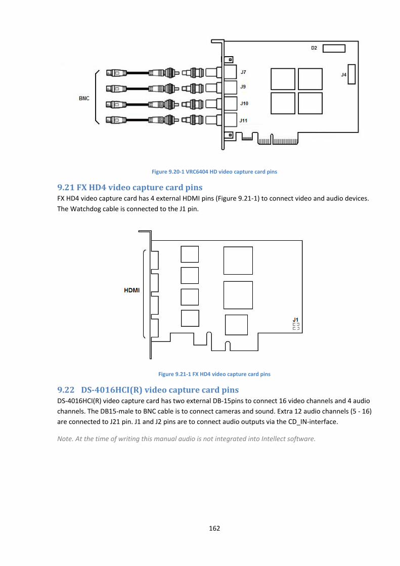
162
Figure 9.20-1 VRC6404 HD video capture card pins
9.21 FX HD4 video capture card pins FX HD4 video capture card has 4 external HDMI pins (Figure 9.21-1) to connect video and audio devices.
The Watchdog cable is connected to the J1 pin.
Figure 9.21-1 FX HD4 video capture card pins
9.22 DS-4016HCI(R) video capture card pins DS-4016HCI(R) video capture card has two external DB-15pins to connect 16 video channels and 4 audio
channels. The DB15-male to BNC cable is to connect cameras and sound. Extra 12 audio channels (5 - 16)
are connected to J21 pin. J1 and J2 pins are to connect audio outputs via the CD_IN-interface.
Note. At the time of writing this manual audio is not integrated into Intellect software.
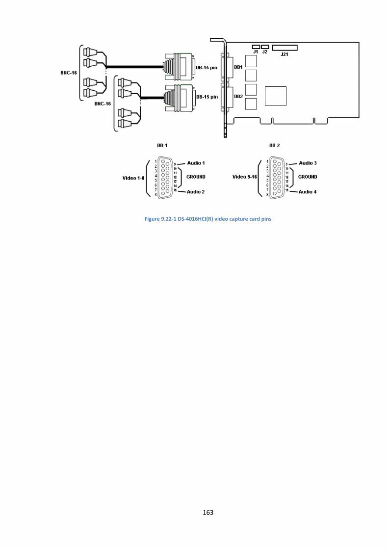
163
Figure 9.22-1 DS-4016HCI(R) video capture card pins
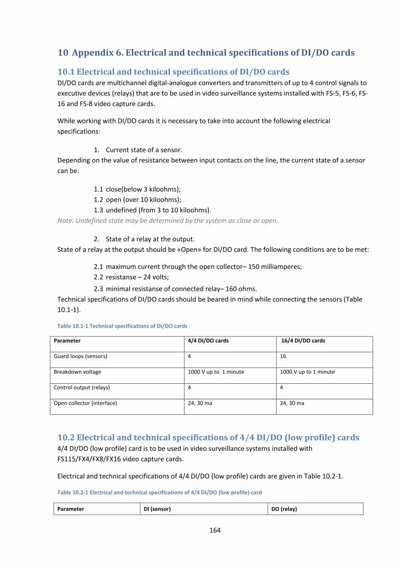
164
10 Appendix 6. Electrical and technical specifications of DI/DO cards
10.1 Electrical and technical specifications of DI/DO cards DI/DO cards are multichannel digital-analogue converters and transmitters of up to 4 control signals to
executive devices (relays) that are to be used in video surveillance systems installed with FS-5, FS-6, FS-
16 and FS-8 video capture cards.
While working with DI/DO cards it is necessary to take into account the following electrical
specifications:
1. Current state of a sensor.
Depending on the value of resistance between input contacts on the line, the current state of a sensor
can be:
1.1 close(below 3 kiloohms);
1.2 open (over 10 kiloohms);
1.3 undefined (from 3 to 10 kiloohms).
Note. Undefined state may be determined by the system as close or open.
2. State of a relay at the output.
State of a relay at the output should be «Open» for DI/DO card. The following conditions are to be met:
2.1 maximum current through the open collector– 150 milliamperes;
2.2 resistanse – 24 volts;
2.3 minimal resistanse of connected relay– 160 ohms.
Technical specifications of DI/DO cards should be beared in mind while connecting the sensors (Table
10.1-1).
Table 10.1-1 Technical specifications of DI/DO cards
Parameter 4/4 DI/DO cards 16/4 DI/DO cards
Guard loops (sensors) 4 16
Breakdown voltage 1000 V up to 1 minute 1000 V up to 1 minute
Control output (relays) 4 4
Open collector (interface) 24, 30 ma 24, 30 ma
10.2 Electrical and technical specifications of 4/4 DI/DO (low profile) cards 4/4 DI/DO (low profile) card is to be used in video surveillance systems installed with
FS115/FX4/FX8/FX16 video capture cards.
Electrical and technical specifications of 4/4 DI/DO (low profile) cards are given in Table 10.2-1.
Table 10.2-1 Electrical and technical specifications of 4/4 DI/DO (low profile) card
Parameter DI (sensor) DO (relay)

165
Parameter DI (sensor) DO (relay)
Number of guard loops 4 4
Triggering time 0.1 ms OFF -> ON: 3.0 ms ON -> OFF: 2.5 ms
Maximum value of current strength and voltage
direct current: 2 А /24 V alternating current: 1 А/120 V
Triggering level
Up to 5 V Up to 12 V
2.5 В – OFF 2.1 В – ON
4.5 В –OFF 2.1 В – ON
10.3 Electrical and technical specifications of MO USBIO 4x4 devices Power is supplied to MO USBIO 4x4 device via the USB. Maximum permissible current consumed by the
device is not more than 500 ma.
The MO USBIO 4x4 device has a galvanic isolation of DI/DO circuits (sensors and relays) against the USB
(breakdown voltage is 1000 V up to 1 minute). Electrical and technical specifications of MO USBIO 4x4
device are given in Table 10.3-1.
Table 10.3-1 Electrical and technical specifications of MO USBIO 4x4 device
Parameter
Relay (output circuit) Sensor (input circuit)
Number of loops
4 4
Maximum permissible current 400 ma (in any direction)
50 ma (in any direction)
Ampere rating - 8 ma (in any direction)
Voltage rating - 24 V (in any direction)
Maximum permissible voltage 60 V (in any direction)
-
Embedded power supply
- 24 V
10.4 Electrical and technical specifications of SL USBIO («4x4», «16x8»,
«24x4») card Pinout of an external pin of the SL USBIO card is given in Figure 10.4-1.
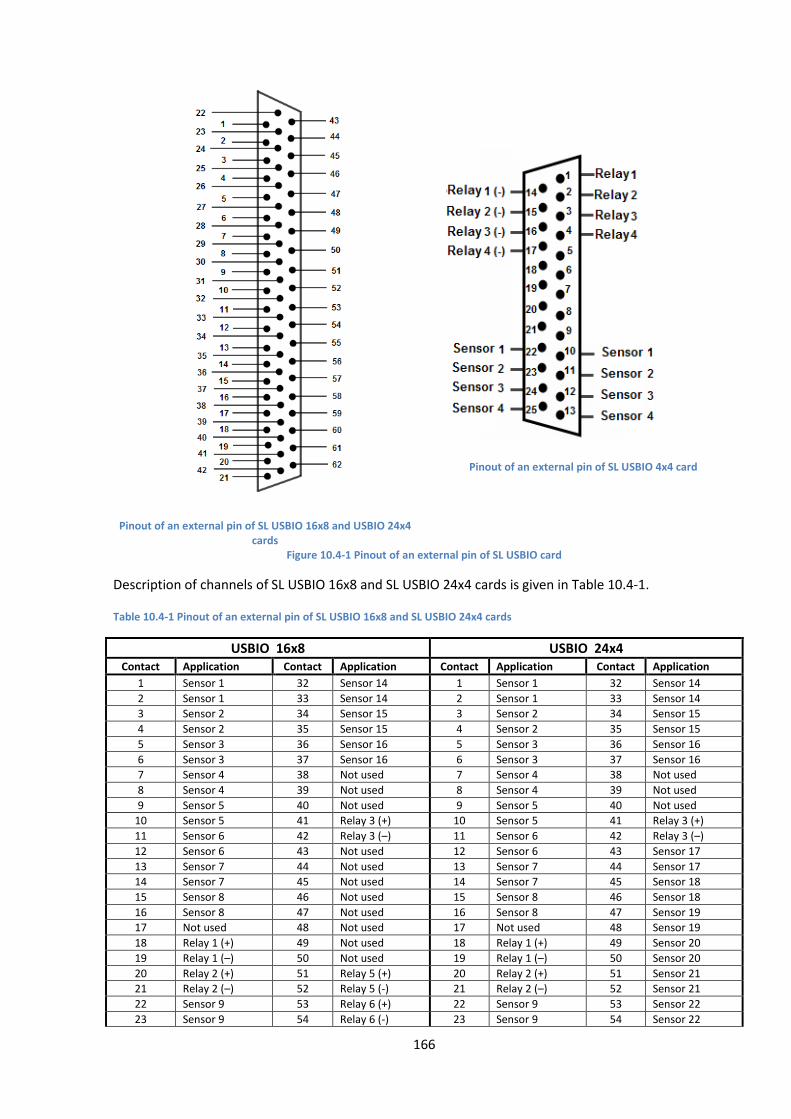
166
Pinout of an external pin of SL USBIO 16x8 and USBIO 24x4
cards
Pinout of an external pin of SL USBIO 4x4 card
Figure 10.4-1 Pinout of an external pin of SL USBIO card
Description of channels of SL USBIO 16x8 and SL USBIO 24x4 cards is given in Table 10.4-1.
Table 10.4-1 Pinout of an external pin of SL USBIO 16x8 and SL USBIO 24x4 cards
USBIO 16x8 USBIO 24x4 Contact Application Contact Application Contact Application Contact Application
1 Sensor 1 32 Sensor 14 1 Sensor 1 32 Sensor 14
2 Sensor 1 33 Sensor 14 2 Sensor 1 33 Sensor 14
3 Sensor 2 34 Sensor 15 3 Sensor 2 34 Sensor 15
4 Sensor 2 35 Sensor 15 4 Sensor 2 35 Sensor 15
5 Sensor 3 36 Sensor 16 5 Sensor 3 36 Sensor 16
6 Sensor 3 37 Sensor 16 6 Sensor 3 37 Sensor 16
7 Sensor 4 38 Not used 7 Sensor 4 38 Not used
8 Sensor 4 39 Not used 8 Sensor 4 39 Not used
9 Sensor 5 40 Not used 9 Sensor 5 40 Not used
10 Sensor 5 41 Relay 3 (+) 10 Sensor 5 41 Relay 3 (+)
11 Sensor 6 42 Relay 3 (–) 11 Sensor 6 42 Relay 3 (–)
12 Sensor 6 43 Not used 12 Sensor 6 43 Sensor 17
13 Sensor 7 44 Not used 13 Sensor 7 44 Sensor 17
14 Sensor 7 45 Not used 14 Sensor 7 45 Sensor 18
15 Sensor 8 46 Not used 15 Sensor 8 46 Sensor 18
16 Sensor 8 47 Not used 16 Sensor 8 47 Sensor 19
17 Not used 48 Not used 17 Not used 48 Sensor 19
18 Relay 1 (+) 49 Not used 18 Relay 1 (+) 49 Sensor 20
19 Relay 1 (–) 50 Not used 19 Relay 1 (–) 50 Sensor 20
20 Relay 2 (+) 51 Relay 5 (+) 20 Relay 2 (+) 51 Sensor 21
21 Relay 2 (–) 52 Relay 5 (-) 21 Relay 2 (–) 52 Sensor 21
22 Sensor 9 53 Relay 6 (+) 22 Sensor 9 53 Sensor 22
23 Sensor 9 54 Relay 6 (-) 23 Sensor 9 54 Sensor 22

167
USBIO 16x8 USBIO 24x4 Contact Application Contact Application Contact Application Contact Application
24 Sensor 10 55 Relay 7 (+) 24 Sensor 10 55 Sensor 23
25 Sensor 10 56 Relay 7 (-) 25 Sensor 10 56 Sensor 23
26 Sensor 11 57 Relay 8 (+) 26 Sensor 11 57 Sensor 24
27 Sensor 11 58 Relay 8 (-) 27 Sensor 11 58 Sensor 24
28 Sensor 12 59 Not used 28 Sensor 12 59 Not used
29 Sensor 12 60 Not used 29 Sensor 12 60 Not used
30 Sensor 13 61 Relay 4 (+) 30 Sensor 13 61 Relay 4 (+)
31 Sensor 13 62 Relay 4 (–) 31 Sensor 13 62 Relay 4 (–)
Electrical and technical specifications of SL USBIO card are given in Table 10.4-2.
Table 10.4-2 Electrical and technical specifications of SL USBIO card
Parameter Characteristic
Polling interval for all alarm inputs 250 ms for all contacts. Not configured.
Galvanic isolation of input/output 1000 V
Interface connection to PC USB 2.0 up to 5 m
Alarm contacts
Maximum current – 0.5 А
Voltage – 100 V
Power – 10 W
Relay contacts
Permissible voltage - up to 80 V
Minimum triggering voltage - 1.0 V
Minimum triggering current - 5 ma
Real-time clock for event logging Yes
ROM For 1000 alarm events
Power supply Using USB port or PSU, voltage - 9-50 V, consumption - 500 ma