Intel® Visual Compute Accelerator VCA8LVV · 3.4.1 12V AUX Power Connector Specification and...
30
Intel® Visual Compute Accelerator VCA1283LVV Product Specification and Hardware User’s Guide A reference document used to provide a high level overview of product features and support requirements. Revision 1.6.3 February 2018 Intel® Server Boards and Systems
Transcript of Intel® Visual Compute Accelerator VCA8LVV · 3.4.1 12V AUX Power Connector Specification and...
Intel® Visual Compute Accelerator VCA1283LVV
Product Specification and Hardware User’s Guide
A reference document used to provide a high level overview of product features and support
requirements.
Revision 1.6.3
February 2018
Intel® Server Boards and Systems

Intel® Visual Compute Accelerator Product Specification and Hardware User’s Guide
i
Document Revision History
Date Published Revision Revision Change Description October 2015 1.0 Production - First Public Release
November 2015 1.1 Added Max TDP data to Board Feature set table in section 2.2
March 2016 1.2 Removed Hynix from memory list in section 4.3
April 2016 1.3 Added Host BIOS and Memory requirements (Sections 2.3-2.4), updated URLs/QR codes
May 2016 1.4 Added BIOS/EEPROM compatibility matrix
July 2016 1.4.1 Updated System Compatibility list in section 2.6
August 2016 1.4.2 Change GPU maximum frequency from 1.15GHz to 1.0GHz
October 2016 1.4.3 Aligned with 1.3 VCA Software Public Release
November 2016 1.4.4 Update VCA System Compatibility List
January 2017 1.4.5 Update Memory Compatibility List
July 2017 1.5 Updated VCA System Compatibility List
October 2017 1.6 Updated VCA System Compatibility List
November 2017 1.6.1 Updated Memory Compatibility List
February 2018 1.6.3 Updated VCA System Compatibility List

Intel® Visual Compute Accelerator Product Specification and Hardware User’s Guide
ii
Disclaimer
Intel technologies’ features and benefits depend on system configuration and may require enabled
hardware, software or service activation. Learn more at Intel.com, or from the OEM or retailer.
You may not use or facilitate the use of this document in connection with any infringement or other legal
analysis concerning Intel products described herein. You agree to grant Intel a non-exclusive, royalty-free
license to any patent claim thereafter drafted which includes subject matter disclosed herein.
No license (express or implied, by estoppel or otherwise) to any intellectual property rights is granted by this
document.
The products described may contain design defects or errors known as errata which may cause the product
to deviate from published specifications. Current characterized errata are available on request.
Intel disclaims all express and implied warranties, including without limitation, the implied warranties of
merchantability, fitness for a particular purpose, and non-infringement, as well as any warranty arising from
course of performance, course of dealing, or usage in trade.
Intel, the Intel logo, and Intel Xeon, are trademarks of Intel Corporation in the U.S. and/or other countries.
*Other names and brands may be claimed as the property of others.
Copyright © 2016-2017 Intel Corporation. All Rights Reserved.

Intel® Visual Compute Accelerator Product Specification and Hardware User’s Guide
iii
Table of Contents
DOCUMENT REVISION HISTORY ......................................................................................................................................................... I
DISCLAIMER ........................................................................................................................................................................................... II
1. INTRODUCTION.............................................................................................................................................................................1
1.1 DOCUMENT OUTLINE ........................................................................................................................................................................................... 1 1.2 OTHER REFERENCE MATERIALS .......................................................................................................................................................................... 1
2. PRODUCT OVERVIEW ..................................................................................................................................................................2
2.1 ORDER INFORMATION ........................................................................................................................................................................................... 2 2.2 FEATURE SET ......................................................................................................................................................................................................... 3 2.3 HOST SYSTEM REQUIRED BIOS FEATURES ..................................................................................................................................................... 4 2.4 INTEL® VISUAL COMPUTE ACCELERATOR EEPROM/SOFTWARE RELEASE COMPATIBILITY MATRIX .................................................... 5 2.5 HOST SYSTEM MINIMUM MEMORY REQUIREMENTS ....................................................................................................................................... 5 2.6 SYSTEM COMPATIBILITY LIST.............................................................................................................................................................................. 6 2.7 ARCHITECTURE BLOCK DIAGRAM ....................................................................................................................................................................... 7
3. BOARD SPECIFICATIONS & SUPPORT REQUIREMENTS .....................................................................................................8
3.1 MECHANICAL SPECIFICATION .............................................................................................................................................................................. 8 3.2 VCA CARD ASSEMBLY ......................................................................................................................................................................................... 8 3.3 THERMAL AND AIR FLOW SPECIFICATION ......................................................................................................................................................... 9 3.4 POWER SPECIFICATION ..................................................................................................................................................................................... 11
3.4.1 12V AUX Power Connector Specification and Pinout ......................................................................................................... 11
4. MEMORY ...................................................................................................................................................................................... 13
4.1 MEMORY POPULATION RULES ......................................................................................................................................................................... 13 4.2 SUPPORTED MEMORY ....................................................................................................................................................................................... 13 4.3 MEMORY COMPATIBILITY LIST ......................................................................................................................................................................... 14
5. OPERATING SYSTEM SUPPORT ............................................................................................................................................. 15
5.1 SUPPORTED HOST OPERATING SYSTEMS ..................................................................................................................................................... 15 5.1.1 Reference boot OS on Visual Compute Accelerator ............................................................................................................ 15
5.2 SUPPORTED HYPERVISOR ................................................................................................................................................................................. 15 5.3 GUEST OS ........................................................................................................................................................................................................... 15
6. LIGHT GUIDED DIAGNOSTICS ................................................................................................................................................. 16
6.1 POWER LEDS ..................................................................................................................................................................................................... 16 6.2 PROCESSOR CATERR LEDS ........................................................................................................................................................................... 16
7. BIOS IMAGE SELECTION JUMPERS ....................................................................................................................................... 17
APPENDIX A: INTEL SERVER SYSTEM SUPPORT ........................................................................................................................ 18

Intel® Visual Compute Accelerator Product Specification and Hardware User’s Guide
iv
List of Figures
Figure 1. Product Architectural Block Diagram ...................................................................................................................... 7
Figure 2. VCA Card Power Connectors ................................................................................................................................... 11
Figure 3. VCA Card DIMM Slots .................................................................................................................................................. 13
Figure 4. Light Guided Diagnostics - Power State LEDs .................................................................................................. 16
Figure 5. Light Guided Diagnostics - Processor CATERR LEDs .................................................................................... 16
Figure 6. VCA Card BIOS Recovery Jumpers........................................................................................................................ 17
Figure 7. 2-Slot PCIe Riser Card ................................................................................................................................................. 18
Figure 8. Auxiliary 12V Power Cable (iPC AXXGPGPUCABLE) ...................................................................................... 19
Figure 9. Air Duct included in Intel® Accessory Kit AWTCOPRODUCT ..................................................................... 19
Figure 10. Shipping Bracket ........................................................................................................................................................ 20
Figure 11. Shipping Bracket Placement ................................................................................................................................. 21

Intel® Visual Compute Accelerator Product Specification and Hardware User’s Guide
1
1. Introduction
This document provides a high level overview of the product features, functions, and support requirements
of the Intel® Visual Compute Accelerator (VCA) card.
1.1 Document Outline
This document is divided into the following chapter:
Chapter 1 – Introduction
Chapter 2 – Product Overview
Chapter 3 – Board Specifications and Support Requirements
Chapter 4 – Memory Support
Chapter 5 – Operating System Support
Chapter 6 – Light Guided Diagnostics
Chapter 7 – BIOS Image Selection Jumpers
Appendix A – Intel® Server System Support Requirements
1.2 Other Reference Materials
Intel® Visual Compute Accelerator Product Software Guide
For more information on the Intel® Visual Compute Accelerator: http://www.intelserveredge.com/intelvca/
For more information on Intel server solutions visit: http://www.intelserveredge.com
For product specifications visit: http://ark.intel.com/
To obtain technical documents, please visit: http://www.intel.com/support/go/visual-accelerator
To obtain the latest download, please visit: https://downloadcenter.intel.com/product/87380/

Intel® Visual Compute Accelerator Product Specification and Hardware User’s Guide
2
2. Product Overview
The Intel® Visual Compute Accelerator card combines the Intel® Iris Pro Graphics capabilities of the Intel®
Xeon® E3-1200 v4 series processor with the power of Intel® Xeon® E5-2600 v3 series processor based server
systems. Designed around visual computing workloads, this PCIe add-in card can handle the highest end
4K/HEVC transcoding jobs as well as many simultaneous AVC jobs. Built for cloud service providers, Telco
service providers and broadcasters who need media transcoding acceleration for the growing video market.
Outstanding Performance / Power / Price per transcode
Real time HEVC transcode performance delivered at low cost and power
Fit within Intel® Xeon® Processor E5 Infrastructure
Multiple 1U and 2U Server System options from several server system suppliers
PCIe* 3.0 x16 enables fast communication between host and adapter
Flexible and Portable software architecture
Full access to integrated CPU & GPU for best quality/performance
Virtual network allows host and card to communicate seamlessly
Strong ISV ecosystem for ease of solution deployment
2.1 Order Information
Intel Product Code Order Information Product Description Product Type
iPC – VCA1283LVV
MM# – 942876
UPC – 0735858309493
EAN – 5032037081986
MOQ – 1
Intel® Visual Compute Accelerator Card
(1) PCIe* add-in-card with 3 x Intel® Xeon®
processor E3-1200 v4 series product family,
6 DIMM slots – 2 DIMMs / CPU
(1) Quick Start Guide
PCIe* Add-in Card
Intel® Visual Compute Accelerator Product Specification and Hardware User’s Guide
3
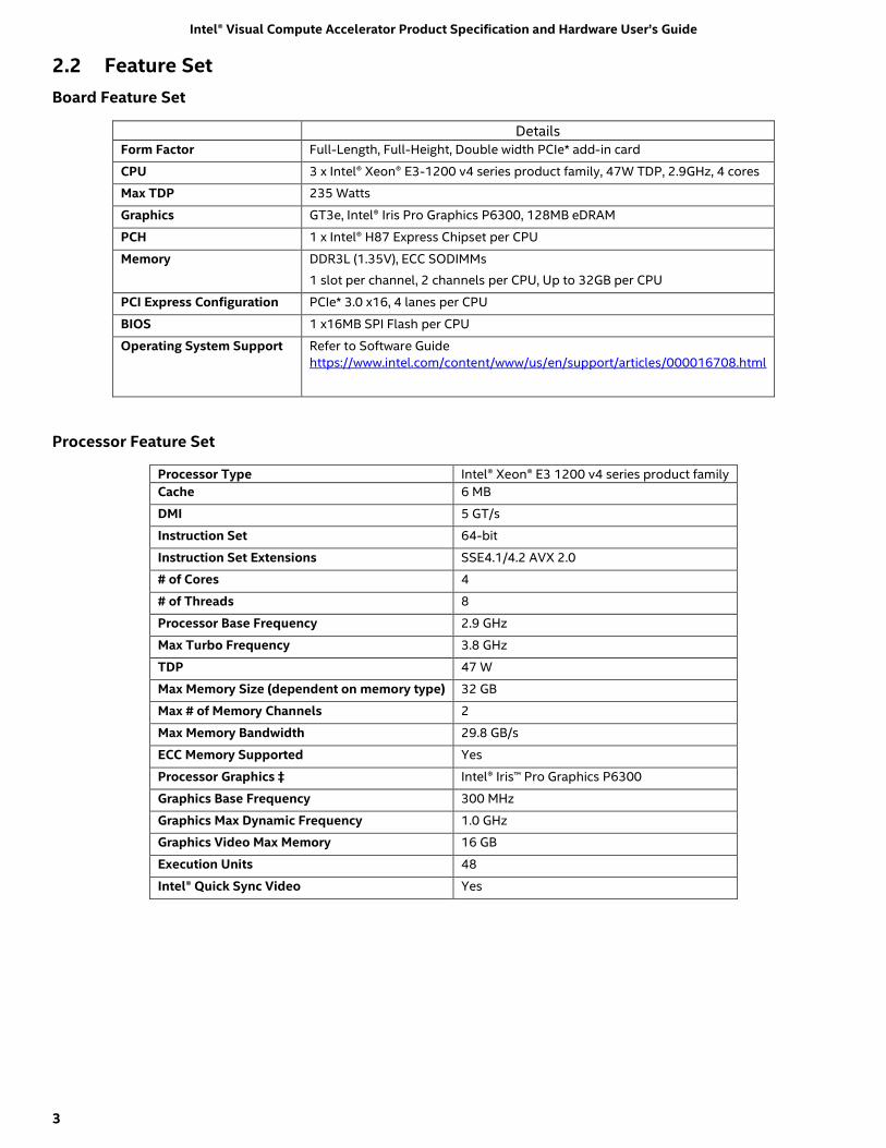
2.2 Feature Set
Board Feature Set
Details Form Factor Full-Length, Full-Height, Double width PCIe* add-in card
CPU 3 x Intel® Xeon® E3-1200 v4 series product family, 47W TDP, 2.9GHz, 4 cores
Max TDP 235 Watts
Graphics GT3e, Intel® Iris Pro Graphics P6300, 128MB eDRAM
PCH 1 x Intel® H87 Express Chipset per CPU
Memory DDR3L (1.35V), ECC SODIMMs
1 slot per channel, 2 channels per CPU, Up to 32GB per CPU
PCI Express Configuration PCIe* 3.0 x16, 4 lanes per CPU
BIOS 1 x16MB SPI Flash per CPU
Operating System Support Refer to Software Guide
https://www.intel.com/content/www/us/en/support/articles/000016708.html
Processor Feature Set
Processor Type Intel® Xeon® E3 1200 v4 series product family
Cache 6 MB
DMI 5 GT/s
Instruction Set 64-bit
Instruction Set Extensions SSE4.1/4.2 AVX 2.0
# of Cores 4
# of Threads 8
Processor Base Frequency 2.9 GHz
Max Turbo Frequency 3.8 GHz
TDP 47 W
Max Memory Size (dependent on memory type) 32 GB
Max # of Memory Channels 2
Max Memory Bandwidth 29.8 GB/s
ECC Memory Supported Yes
Processor Graphics ‡ Intel® Iris™ Pro Graphics P6300
Graphics Base Frequency 300 MHz
Graphics Max Dynamic Frequency 1.0 GHz
Graphics Video Max Memory 16 GB
Execution Units 48
Intel® Quick Sync Video Yes

Intel® Visual Compute Accelerator Product Specification and Hardware User’s Guide
4
2.3 Host System Required BIOS Features
The host system BIOS must support the following features:
For Intel® VCA Software release 1.0:
Support for large MMIO space (minimum 192 GB per card)
Support for large BAR allocations (must support 64 GB allocation per device)
For Intel® VCA Software releases 1.2 and 1.3 :
Support for large MMIO space (3 GB + 768 KB per card)
Support for large BAR allocations (must support 1 GB allocation per device)

Intel® Visual Compute Accelerator Product Specification and Hardware User’s Guide
5
2.4 Intel® Visual Compute Accelerator EEPROM/Software Release Compatibility
Matrix
VCA SW-HW Configuration
Advisory
VCA SW 1.0
on host
VCA SW 1.2
on host
VCA SW 1.3
on host
Host Server BIOS
Settings
VCA HW 1.0 PLX EEPROM
(serial # QSVV549xxxxx / PBA
ending in -404 )
Valid
Configuration
Customer can
upgrade to SW
1.2
Valid
Configuration
But to take
advantage of
improvements of
SW 1.2 (eg,
smaller MMIO),
customers need
to upgrade
EEPROM and
BIOS to SW 1.2
Valid
Configuration
But to take
advantage of
improvements of
SW 1.3 (eg,
higher
performance),
customers need
to upgrade BIOS ,
EEPROM and OS
to SW 1.3
Required:
MMIO: >= 192 GB per Intel® VCA
installed in the host
BAR: >= 64 GB per device
VCA HW 1.2 PLX EEPROM
(serial # QSVV61xxxxxx / PBA
ending in -405)
NOT VALID
Host server will
not recognize
VCA HW
Valid
Configuration
Valid
configuration
But to take
advantage of
improvements of
SW 1.3 (eg,
higher
performance),
customers need
to upgrade BIOS
and OS to SW 1.3
Required*:
MMIO: >= (3GB + 768 KB) per Intel®
VCA card installed in the host
BAR: >= 1 GB per device
* Note that VCA HW 1.0 PLX host BIOS
settings are supported, as well, as they
are a superset of these requirements
VCA HW 1.3 PLX EEPROM
(serial # QSVV61xxxxxx / PBA
ending in -500)
NOT VALID
Host server will
not recognize
VCA HW
Valid
Configuration
Valid
Configuration
Required*:
MMIO: >= (3GB + 768 KB) per Intel®
VCA card installed in the host
BAR: >= 1 GB per device
* Note that VCA HW 1.0 PLX host BIOS
settings are supported, as well, as they
are a superset of these requirements
2.5 Host System Minimum Memory Requirements
The Host System must have sufficient free RAM (after accounting for operating system, running services and
applications) to load the Bootable image for each node that will be simultaneously booted. (e.g., if a 2GB
bootable image is to be booted simultaneously on 4 cards (12 nodes), there must be at least 24GB (2GB x 12
nodes) free RAM when the boot command is issued.)

Intel® Visual Compute Accelerator Product Specification and Hardware User’s Guide
6
2.6 System Compatibility List
The Intel® Visual Compute Accelerator card is compatible with the following server systems. This section will
be updated as additional server systems are validated by Intel or by the specified server supplier. Please
refer to https://www.intel.com/content/www/us/en/support/articles/000016707/server-products/server-
accessories.html to check the list or refer to the table below:
Number of VCA cards 1U Rack Server 2U Rack Server
2 units Supermicro
-Supermicro* SuperServer SYS1018GR-T
Intel
-SKUs include:
R2308WTxxxx
R2208WTxxxx
R2216WTxxxx
R2308WFxxxx
R2208WFxxxx
R2212WFxxxx
Requires:
2U 2-slot PCIe* Riser card Option -
A2UL16RISER2
2U High Air Flow Air Duct Kit –
AWTCOPRODUCT (for R2000WT)
AWFCOPRODUCT (for R2000WF)
Software package 2.0.x or later (for
R2000WF)
Sugon
-Sugon* W760-G20
3 units Advantech
-Advantech* AGS-913
4 units Dell
-Dell* PowerEdge C4130 (Note1)
Gigabyte
-Gigabyte* G190-H44
Inspur
-Inspur* NF5280M4
8 units Gigabyte
-Gigabyte* G25N-G51/ G250-G52/ G250-
G51/ G250-G50/ G250-S88
Note1:
1. Special Dell custom mounting hardware is required.
2. Special Dell customized BIOS is required.
Note: Please contact third party system manufacturers directly to verify ordering options required to support
Intel® Visual Compute Accelerator; the system names here may need OEM modifications to fully support this
device.

Intel® Visual Compute Accelerator Product Specification and Hardware User’s Guide
7
2.7 Architecture Block Diagram
Figure 1. Product Architectural Block Diagram

Intel® Visual Compute Accelerator Product Specification and Hardware User’s Guide
8
3. Board Specifications & Support Requirements
3.1 Mechanical Specification
The Intel® Visual Compute Accelerator is a “near” full length, full height, double width PCIe* 3.0 x16 add-in
card. It includes a bracket that extends the card to full length for systems that fully support the PCIe*
specification.
3.2 VCA Card Assembly
The VCA card assembly consists of several detachable components to allow for card configuration and
serviceability. The following illustration displays the full card assembly.
Mechanical
Support Bracket

Intel® Visual Compute Accelerator Product Specification and Hardware User’s Guide
9
Advisory Note:
The Intel® Visual Compute Accelerator card must have the provided mechanical support bracket (or other
custom support bracket) mounted to the card to ensure proper support when installed in the system. Failure
to properly support the installed card may cause serious damage should the system be exposed to any level
of shock or vibration or is transported to the end user location.
When in operation, the VCA card will get hot. The card covers must be in place to allow for proper air flow
over and through the card assembly. Failure to have the card covers installed will result in the card
overheating which may impact card performance or proper operation.
3.3 Thermal and Air Flow Specification
The following illustration and table identify the thermal, air flow, and air pressure requirements that must be
met by a chassis following a common front of system to back of system air flow pattern.
Card Inlet Temp *Flow Rate *Pressure Drop
45° C 25.5 CFM 0.476 “H2O
35° C 18.0 CFM 0.246 “H2O
*CFM=Cubic Feet per Minute
*“H2O= Inches of Water
Some custom chassis configurations may orient the card such that the air flow is reversed from the standard
air flow pattern shown above. In these non-standard system configurations the thermal, air flow, and air
pressure boundary conditions must meet the following requirements.
Air Flow In
(Card Inlet)
Air Flow Out
Standard Air Flow Pattern

Intel® Visual Compute Accelerator Product Specification and Hardware User’s Guide
10
*CFM=Cubic Feet per Minute
*“H2O= Inches of Water
Note: VCA card CPU core temperatures must remain at or below 96° C (204.8° F). CPU’s will begin to
throttle once they reach 105° C (221° F), impacting card performance. Should CPU temperatures continue to
rise, the card may shut down due to a CPU Thermal Trip event. Should such events occur, system
administrators must make adjustments to the system fan speed controls to ensure increased air flow to the
VCA card.
System administrators can utilize the “vcactl temp” command of the vcactl utility to monitor VCA CPU core
temperatures.
Card Inlet Temp *Flow Rate *Pressure Drop
35° C 24.1 CFM 0.208 “H2O
25° C 19.0 CFM 0.196 “H2O
Air Flow In
(card inlet)
Air Flow Out
Non-Standard Air Flow Pattern

Intel® Visual Compute Accelerator Product Specification and Hardware User’s Guide
11
3.4 Power Specification
The Intel® Visual Compute Accelerator card has a max TDP of 235W. Per the PCIe* specification, the PCIe
x16 connector can support up to 75W. The remaining power to the card must be supplied via the 2x3 (75W)
and 2x4 (150W) 12V AUX power connectors on the card as shown in the following illustration.
Figure 2. VCA Card Power Connectors
Note: The Intel® Visual Compute Accelerator card does not ship with cables. Contact the system supplier for
12V AUX power cables appropriate for the system to which the card is being installed. See Appendix A for
Intel® Server System support.
3.4.1 12V AUX Power Connector Specification and Pinout
- 2 x 3 Pin 12V AUX Power Connector
Vendor – Lotes*
Vendor Part # - APOW0001-P001C01
Pin# Description
1 12V
2 12V
3 12V
4 GND
5 GND
6 GND
(2 x 3) Pin 12V AUX
up to 75W
(2 x 4) Pin 12V AUX
up to 150W
PCIe* Edge
Connector
up to 75W
Intel® Visual Compute Accelerator Product Specification and Hardware User’s Guide
12
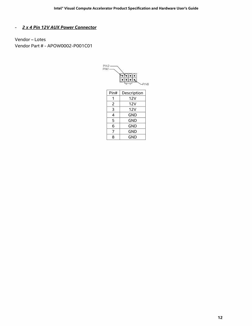
- 2 x 4 Pin 12V AUX Power Connector
Vendor – Lotes
Vendor Part # - APOW0002-P001C01
Pin# Description
1 12V
2 12V
3 12V
4 GND
5 GND
6 GND
7 GND
8 GND

Intel® Visual Compute Accelerator Product Specification and Hardware User’s Guide
13
4. Memory
The Intel® Visual Compute Accelerator card includes three processors identified as CPU 1-3. Each of the
three processors include two memory channels identified as A and B. Each memory channel supports one
SODIMM socket. Each processor can support up to 32GB of memory. The illustration below identifies the
SODIMM sockets for each processor.
Figure 3. VCA Card DIMM Slots
4.1 Memory Population Rules
Note: Although mixed DIMM configurations may be functional, Intel only supports and performs validation
with cards that are configured with identical DIMMs installed across all CPUs
All DIMMs must be DDR3 DIMMs
Only Error Correction Code (ECC) enabled DIMMs are supported
All processors must have at least one DIMM installed
DIMM slots for each processor must be installed in order beginning with DIMM Slot A
When only one DIMM is installed for any given processor, it must be populated in the DIMM A slot.
4.2 Supported Memory
The Intel® Visual Compute Accelerator card has support for the following memory type:
Memory Type Memory Size Speed Ranks per DIMM SODIMM DDR3 x8 ECC 8GB, 16GB 1333, 1600, 1866 SR, DR
CPU1 DIMM-A CPU1 DIMM-B CPU3 DIMM-A CPU3 DIMM-B
CPU2 DIMM-A CPU2 DIMM-B
Intel® Visual Compute Accelerator Product Specification and Hardware User’s Guide
14
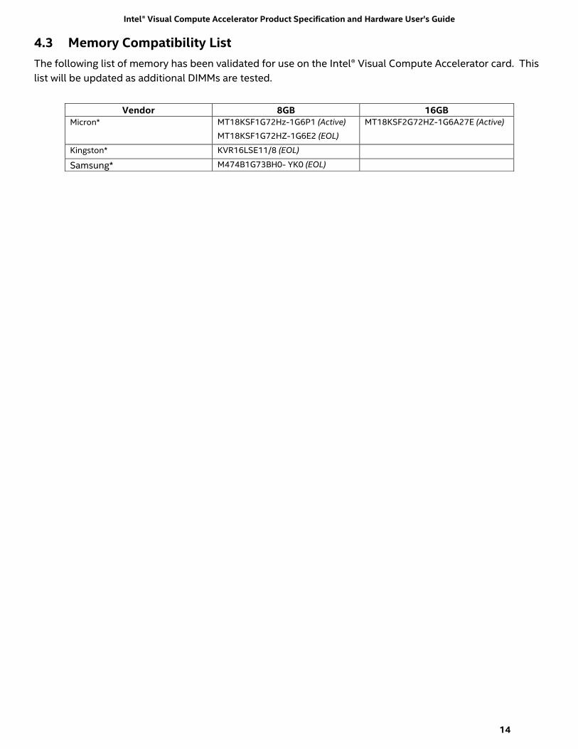
4.3 Memory Compatibility List
The following list of memory has been validated for use on the Intel® Visual Compute Accelerator card. This
list will be updated as additional DIMMs are tested.
Vendor 8GB 16GB Micron* MT18KSF1G72Hz-1G6P1 (Active)
MT18KSF1G72HZ-1G6E2 (EOL)
MT18KSF2G72HZ-1G6A27E (Active)
Kingston* KVR16LSE11/8 (EOL)
Samsung* M474B1G73BH0- YK0 (EOL)

Intel® Visual Compute Accelerator Product Specification and Hardware User’s Guide
15
5. Operating System Support
Note: All utility software and boot images referenced in this section can be downloaded from the following
Intel web site: https://downloadcenter.intel.com/product/87380
The Intel® Visual Compute Accelerator boots the operating system from the host using a technology known
as Leverage Boot. A “vcactl” utility is used to perform all boot operations. The utility loads the operating
system into a RAMDisk which the CPU’s boot from.
Users have the option of downloading one of several different boot images available from the Intel web site
or creating their own boot image. Refer to the Intel® Visual Compute Accelerator Product Software Users
Guide for instructions on how to build a boot image.
Alternatively, an option for building a guest OS with pass through graphics is available by using GVT-d
virtualization.
For the host operating system, a virtIO driver and a utility are required. The driver and utility are currently
tested with CentOS* 7 (kernel update require).
Disclaimer Note: As these drivers are open source, the option to build them for other Linux based operating
systems is available, however Intel cannot provide support for this option without official validation being
performed by Intel. Driver validation and performance tuning will be the responsibility of those that choose
to build drivers for Linux Operating systems beyond those supported by Intel.
5.1 Supported Host Operating Systems
- CentOS* 7 with kernel update
Note: specific CentOS version and kernel updates are documented in the Intel® Visual Compute Accelerator
Product Software Users Guide.
5.1.1 Reference boot OS on Visual Compute Accelerator
CentOS 7 with kernel update
- Persistent Image – Automatically mounts to pre-defined NFS partition on the host. Enables all
changes to remain persistent
- Baremetal Image – Full CentOS 7 image. By default nothing is persistent.
- w/ Xen Option
5.2 Supported hypervisor
- Xen
5.3 Guest OS
Any OS supported by Intel® Iris Pro Graphics, GVT-d virtualization, and the Intel® Media Server Studio

Intel® Visual Compute Accelerator Product Specification and Hardware User’s Guide
16
6. Light Guided Diagnostics
The Intel® Visual Compute Accelerator Board includes several LEDs to indicate the health of the card.
6.1 Power LEDs
Two LEDs located on the back edge of the card, and visible externally from the back of the system, are used
to indicate the status of power to the board. One AMBER LED to indicate the status of 3.3V auxiliary power
and one GREEN LED to indicate the status of 3.3V main power. Each LED should be illuminated when power
is present.
Figure 4. Light Guided Diagnostics - Power State LEDs
6.2 Processor CATERR LEDs
Three LEDs on the back side of the board (viewable when the system is open) are used to indicate when a
CATERR for a specific CPU has occurred. When a CATERR on a specific CPU is detected, the given LED will
illuminate RED. In a normal state, these LEDs are not illuminated.
Figure 5. Light Guided Diagnostics - Processor CATERR LEDs
3.3V AUX
Power
3.3V Main
Power
CPU 1
CATERR
CPU 2
CATERR CPU 3
CATERR

Intel® Visual Compute Accelerator Product Specification and Hardware User’s Guide
17
7. BIOS Image Selection Jumpers
The Intel® Visual Compute Accelerator card includes three 16MB SPI Flash devices to store separate BIOS
images for each processor. Each flash device will store two BIOS images; a locked factory default image, and
a modifiable User Defined image. As shipped from Intel, both BIOS images for each processor will be the
factory default.
On the back edge of the VCA card is a set of three jumper blocks. Each jumper block is used to switch the
BIOS image for a given processor between the User Defined and the Factory Default. With the jumper in
place over the two stake pins (Default), the processor will boot using the User BIOS image. In the rare event
the User Image should get corrupted, the jumper can be removed to boot the processor using the Factory
Default image.
NOTE: All three jumper blocks should either be installed or removed together. At no time should one jumper
setting be different from the other two.
NOTE: The back edge of the VCA card includes several stake pins that are not used and have no functionality.
Care should be taken when restoring BIOS Image jumper blocks to their proper stake pin locations. See
Figure 6
Figure 6. VCA Card BIOS Recovery Jumpers

Intel® Visual Compute Accelerator Product Specification and Hardware User’s Guide
18
Appendix A: Intel Server System Support
Intel® Server System R2000WT product family
Server System
8 R2208WTTYC1R - full server system with full support for 2x Intel® Visual Compute Accelerator cards
Support Criteria
Due to air flow and thermal limitations, the Intel® Visual Compute Accellerator card can only be supported
in the following base Intel Server System R2000WT system models: R2208WTxxxx.
Components
1x R2000WTXXX + 1x AWTCOPRODUCT + (1x or 2x) A2UL16RISER2 (if 1, also add 1x A2UL8RISER2) + 2x
AXX1100PCRPS + 1x (A2U8X25S3HSDK (no NVMe support) OR A2U44X25NVMEDK2 (with NVMe
support). Processors, memory, drives, and additional add-in cards sold separately.
The Intel® Visual Compute Accellerator card must be installed into the top slot of a 2-Slot PCIe* Riser
card. With a 2-slot riser card installed, the embedded fan speed control will operate system fans at a
higher speed. 3-slot riser cards (as shipped in the standard platform configuration) cannot be used due
to air flow and thermal limitations, as embedded fan speed control will not drive system fans to higher
speeds needed to support the thermal requirements of this card.
Figure 7. 2-Slot PCIe Riser Card
:
Slot # Description PCIe* Lane Routing
Riser Slot #1
PCIe* Lane Routing
Riser Slot #2
Slot-1 (Top) PCIe x16 lanes, x16 slot CPU1 CPU2
Slot-2 (Bottom) PCIe x8 lanes, x8 slot CPU2 CPU2
Intel® Visual Compute Accelerator Product Specification and Hardware User’s Guide
19
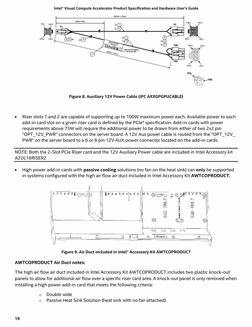
Figure 8. Auxiliary 12V Power Cable (iPC AXXGPGPUCABLE)
Riser slots 1 and 2 are capable of supporting up to 100W maximum power each. Available power to each
add-in card slot on a given riser card is defined by the PCIe* specification. Add-in cards with power
requirements above 75W will require the additional power to be drawn from either of two 2x2 pin
“OPT_12V_PWR” connectors on the server board. A 12V Aux power cable is routed from the “OPT_12V_
PWR” on the server board to a 6 or 8 pin 12V AUX power connector located on the add-in cards.
NOTE: Both the 2-Slot PCIe Riser card and the 12V Auxiliary Power cable are included in Intel Accessory kit
A2UL16RISER2
High power add-in cards with passive cooling solutions (no fan on the heat sink) can only be supported
in systems configured with the high air flow air duct included in Intel Accessory Kit AWTCOPRODUCT.
Figure 9. Air Duct included in Intel® Accessory Kit AWTCOPRODUCT
AWTCOPRODUCT Air Duct notes:
The high air flow air duct included in Intel Accessory Kit AWTCOPRODUCT includes two plastic knock-out
panels to allow for additional air flow over a specific riser card area. A knock-out panel is only removed when
installing a high power add-in card that meets the following criteria:
o Double wide
o Passive Heat Sink Solution (heat sink with no fan attached)

Intel® Visual Compute Accelerator Product Specification and Hardware User’s Guide
20
If the add-in card does NOT meet these criteria, the given knock-out panel should NOT be removed.
When installing a double wide add-in card with a passive heat sink solution, remove only the plastic knock-
out from the side on which the add-in card is installed. Only remove both plastic knock outs when installing
two cards that meet the criteria defined above (1 per riser card). Once a knock-out panel is removed, it
cannot be re-installed.
A system configured with the contents of Intel Accessory Kit AWTCOPRODUCT and an Intel® Visual
Compute Accellerator card can also support the following additional PCIe* add-in card configurations.
o PCIe* add-in cards with minimum 100 LFM (0.5 m/s) or 200 LFM (1m/s) air flow requirement can
be installed in any available add-in card slot in Riser Card #1, Riser Card #2, and Riser Card #3 (if
installed)
o PCIe* add-in cards with a minimum 300 LFM (1.5 m/s) air flow requirement can be installed in the
bottom add-in card slot of Riser Card #1 and Riser Card #2.
o PCIe* add-in cards with air flow requirement greater than 300 LFM cannot be supported
Systems configured with an Intel® Visual Compute Accellerator card card must have a shipping bracket
installed before the system is exposed to any level of shock or vibration or is transported to the end user
location. Failure to install the shipping bracket has the potential to cause serious damage to various
components within the system. The shipping bracket is only available as part of the following Intel
Accessory Kit: AWTCOPRODUCT.
Figure 10. Shipping Bracket
Intel® Visual Compute Accelerator Product Specification and Hardware User’s Guide
21
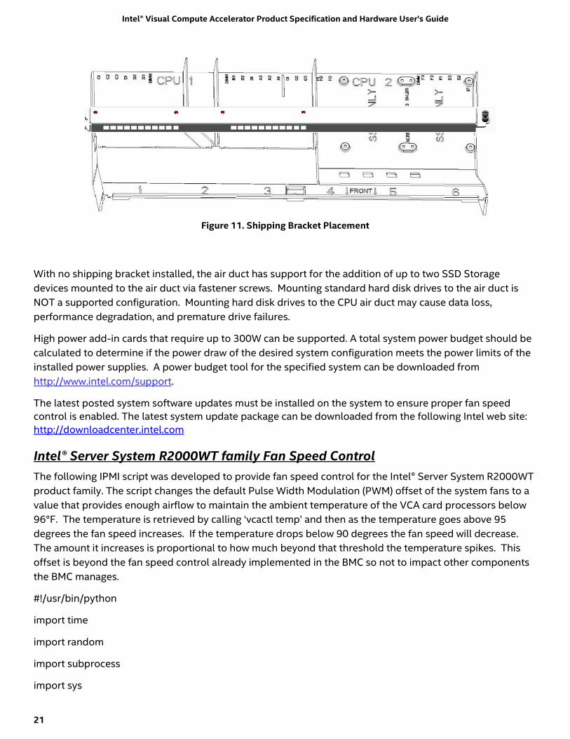
Figure 11. Shipping Bracket Placement
With no shipping bracket installed, the air duct has support for the addition of up to two SSD Storage
devices mounted to the air duct via fastener screws. Mounting standard hard disk drives to the air duct is
NOT a supported configuration. Mounting hard disk drives to the CPU air duct may cause data loss,
performance degradation, and premature drive failures.
High power add-in cards that require up to 300W can be supported. A total system power budget should be
calculated to determine if the power draw of the desired system configuration meets the power limits of the
installed power supplies. A power budget tool for the specified system can be downloaded from
http://www.intel.com/support.
The latest posted system software updates must be installed on the system to ensure proper fan speed
control is enabled. The latest system update package can be downloaded from the following Intel web site:
http://downloadcenter.intel.com
Intel® Server System R2000WT family Fan Speed Control
The following IPMI script was developed to provide fan speed control for the Intel® Server System R2000WT
product family. The script changes the default Pulse Width Modulation (PWM) offset of the system fans to a
value that provides enough airflow to maintain the ambient temperature of the VCA card processors below
96°F. The temperature is retrieved by calling ‘vcactl temp’ and then as the temperature goes above 95
degrees the fan speed increases. If the temperature drops below 90 degrees the fan speed will decrease.
The amount it increases is proportional to how much beyond that threshold the temperature spikes. This
offset is beyond the fan speed control already implemented in the BMC so not to impact other components
the BMC manages.
#!/usr/bin/python
import time
import random
import subprocess
import sys
Intel® Visual Compute Accelerator Product Specification and Hardware User’s Guide
22
import re
import math
from subprocess import call
# will hang if program never exits
def runProcess(exe):
p = subprocess.Popen(exe,stdout=subprocess.PIPE,stderr=subprocess.STDOUT)
out,err = p.communicate();
if (p.returncode>0):
print "Error: Check to ensure vcatl and ipmitool is installed and ipmi service is running"
exit()
return out
def getTemperature():
maxTemp=0
maxTempNode=""
output = runProcess("vcactrl temp".split())
it = re.finditer(r"Card\s*\d{1,2}\s*Cpu\s*\d{1,2}",output)
for match in it:
it2 = re.search(r"Physical id \d{1,2}:\s*\+\d{1,3}",output[match.start():])
if it2:
int_list = [int(s) for s in re.findall('\\d+',it2.group())]
if len(int_list)==2 and int_list[1]>maxTemp:
maxTemp=int_list[1]
maxTempNode=match.group()
print "Highest temperature is",maxTemp,"on node",maxTempNode
return maxTemp
def setPWMOffset(offset):
param="ipmitool raw 0x30 0x8C " + hex(math.trunc(offset))
print "Setting PWM offset to",str(offset)+"%"

Intel® Visual Compute Accelerator Product Specification and Hardware User’s Guide
23
runProcess(param.split())
def getCurrentPWM():
output = runProcess('ipmitool raw 0x30 0x8D'.split())
i = int(output,16)
print "Current PWM offset is",str(i)+"%"
return i
def changeFan(fan,change):
lastFan=fan
fan=fan+change
# assuming lowest possible base fan is 30 so offset above 70 will never take
if fan>70.0:
fan=70.0
if fan<0.0:
fan=0.0
# if nothing changed don't bother running the ipmitool command again
if lastFan==fan:
return fan
setPWMOffset(fan)
print "Fan is at ",fan
return fan
waitTime=10
proportional=2.5
fanChange=5
highTemp=95
lowTemp=90
currentTemp=0
currentFan=getCurrentPWM()

Intel® Visual Compute Accelerator Product Specification and Hardware User’s Guide
24
# main loop
while True:
currentTemp=getTemperature()
if currentTemp >= highTemp:
currentFan=changeFan(currentFan,(currentTemp-highTemp)*proportional)
if currentTemp <= lowTemp:
currentFan=changeFan(currentFan,(currentTemp-lowTemp)*proportional)
time.sleep(waitTime)