Intel Trusted Execution Technologyclass.ece.iastate.edu/tyagi/cpre681/papers/iTXT31516804.pdf ·...
102
Intel® Trusted Execution Technology Intel ® Trusted Execution Technology - Preliminary Architecture Specification 1 Intel ® Trusted Execution Technology Preliminary Architecture Specification — Preliminary Architecture Specification and Enabling Considerations August 2007
Transcript of Intel Trusted Execution Technologyclass.ece.iastate.edu/tyagi/cpre681/papers/iTXT31516804.pdf ·...

Intel® Trusted Execution Technology
Intel® Trusted Execution Technology - Preliminary Architecture Specification 1
Intel® Trusted Execution Technology Preliminary Architecture Specification
— Preliminary Architecture Specification and Enabling Considerations
August 2007

Intel® Trusted Execution Technology
Intel® Trusted Execution Technology - Preliminary Architecture Specification 2
INFORMATION IN THIS DOCUMENT IS PROVIDED IN CONNECTION WITH INTEL® PRODUCTS. NO LICENSE, EXPRESS OR IMPLIED, BY ESTOPPEL OR OTHERWISE, TO ANY INTELLECTUAL PROPERTY RIGHTS IS GRANTED BY THIS DOCUMENT. EXCEPT AS PROVIDED IN INTEL'S TERMS AND CONDITIONS OF SALE FOR SUCH PRODUCTS, INTEL ASSUMES NO LIABILITY WHATSOEVER, AND INTEL DISCLAIMS ANY EXPRESS OR IMPLIED WARRANTY, RELATING TO SALE AND/OR USE OF INTEL PRODUCTS INCLUDING LIABILITY OR WARRANTIES RELATING TO FITNESS FOR A PARTICULAR PURPOSE, MERCHANTABILITY, OR INFRINGEMENT OF ANY PATENT, COPYRIGHT OR OTHER INTELLECTUAL PROPERTY RIGHT.
UNLESS OTHERWISE AGREED IN WRITING BY INTEL, THE INTEL PRODUCTS ARE NOT DESIGNED NOR INTENDED FOR ANY APPLICATION IN WHICH THE FAILURE OF THE INTEL PRODUCT COULD CREATE A SITUATION WHERE PERSONAL INJURY OR DEATH MAY OCCUR.
Intel may make changes to specifications and product descriptions at any time, without notice. Designers must not rely on the absence or characteristics of any features or instructions marked "reserved" or "undefined." Intel reserves these for future definition and shall have no responsibility whatsoever for conflicts or incompatibilities arising from future changes to them. The information here is subject to change without notice. Do not finalize a design with this information.
The products described in this document may contain design defects or errors known as errata which may cause the product to deviate from published specifications. Current characterized errata are available on request.
Contact your local Intel sales office or your distributor to obtain the latest specifications and before placing your product order.
Hyper-Threading Technology requires a computer system with an Intel® Pentium® 4 processor supporting Hyper-Threading Technology and an HT Technology enabled chipset, BIOS and operating system. Performance will vary depending on the specific hardware and software you use.
No computer system can provide absolute security under all conditions. Intel® Trusted Execution Technology (TXT) is a security technology under development by Intel and requires for operation a computer system with Intel® Virtualization Technology, a Intel® Trusted Execution Technology -enabled Intel processor, chipset, BIOS, Authenticated Code Modules, and an Intel or other Intel® Trusted Execution Technology compatible measured virtual machine monitor. In addition, Intel® Trusted Execution Technology requires the system to contain a TPMv1.2 as defined by the Trusted Computing Group and specific software for some uses. See http://www.intel.com/ for more information.
Intel, Pentium, Intel Xeon, Intel NetBurst, Intel Core Solo, Intel Core Duo, Intel Pentium D, Itanium, MMX, and VTune are trademarks or registered trademarks of Intel Corporation or its subsidiaries in the United States and other countries.
*Other names and brands may be claimed as the property of others.
Contact your local Intel sales office or your distributor to obtain the latest specifications and before placing your product order.
Copyright © 2006-2007 Intel Corporation

Intel® Trusted Execution Technology
Intel® Trusted Execution Technology - Preliminary Architecture Specification 3
Contents 1 Overview .........................................................................................................7
1.1 Measurement and Intel® Trusted Execution Technology ...............................8 1.2 Dynamic Root of Trust ............................................................................8
1.2.1 Launch Sequence ......................................................................9 1.3 Storing the Measurement ........................................................................9 1.4 Controlled Take-down ...........................................................................10 1.5 SMX and VMX Interaction ......................................................................10 1.6 Authenticated Code Module....................................................................10 1.7 Chipset Support ...................................................................................10 1.8 TPM Usage ..........................................................................................11
2 Safer Mode Extensions.....................................................................................12 2.1 Detecting and Enabling SMX ..................................................................12
2.1.1 SMX Functionality....................................................................13 2.1.2 Enabling SMX Capabilities.........................................................14
2.2 SMX Instruction Summary .....................................................................15 2.2.1 GETSEC[PARAMETERS] ............................................................15 2.2.2 GETSEC[SMCTRL]....................................................................15 2.2.3 GETSEC[ENTERACCS] ..............................................................15 2.2.4 GETSEC[EXITAC] ....................................................................16 2.2.5 GETSEC[SENTER]....................................................................16 2.2.6 GETSEC[SEXIT] ......................................................................17 2.2.7 GETSEC[WAKEUP]...................................................................17 2.2.8 Launching and Shutting Down a Measured Environment................17
2.3 GETSEC Leaf Functions .........................................................................18 2.3.1 IA32_FEATURE_CONTROL and GETSEC LEAVES...........................19
3 Intel® Trusted Execution Technology Shutdown...................................................50 3.1 Reset Conditions ..................................................................................50
4 DMA Protection...............................................................................................51 4.1 DMA Protected Range (DPR) ..................................................................51 4.2 VT-d Protected Memory Regions (PMRs) ..................................................52
5 Measured Launched Environment ......................................................................53 5.1 MLE Architecture Overview ....................................................................53 5.2 MLE Launch .........................................................................................53
5.2.1 Intel® Trusted Execution Technology Detection and Processor Preparation ............................................................................54
5.2.2 Loading the SINIT AC Module....................................................55 5.2.3 Loading the MLE and Processor Rendezvous ................................57 5.2.4 Performing a Measured Launch..................................................60
5.3 MLE Initialization..................................................................................62 5.4 MLE Operation .....................................................................................66
5.4.1 Address Space Correctness .......................................................66

Intel® Trusted Execution Technology
Intel® Trusted Execution Technology - Preliminary Architecture Specification 4
5.4.2 Address Space Integrity ...........................................................66 5.4.3 Physical RAM Regions ..............................................................67 5.4.4 Intel® Trusted Execution Technology Chipset Regions ...................67 5.4.5 Protecting Secrets ...................................................................68 5.4.6 Machine Specific Register Handling ............................................68 5.4.7 ACPI Power Management Support..............................................69
5.5 MLE Teardown .....................................................................................70 5.6 Other SMX Software Considerations ........................................................73
5.6.1 Saving MSR State Across a Measured Launch ..............................73 Appendix A Intel® TXT Authenticated Code Modules..............................................................74
A.1 Authenticated Code Module Format .........................................................74 A.1.1 Memory type cacheability restrictions.........................................79 A.1.2 Authentication and execution of AC module.................................79
Appendix B SMX Interaction with Platform...........................................................................81 B.1 Intel® Trusted Execution Technology Configuration Registers ......................81 B.2 TPM Platform Configuration Registers ......................................................88 B.3 Intel® Trusted Execution Technology Device Space....................................88
Appendix C Intel® TXT Heap Memory..................................................................................90 C.1 BIOS to OS Data Format .......................................................................91 C.2 OS to MLE Data Format.........................................................................92 C.3 OS to SINIT Data Format.......................................................................92 C.4 SINIT to MLE Data Format .....................................................................93
Appendix D Intel® TXT Technology Enabling Platform............................................................95 D.1 Data Structures....................................................................................95
D.1.1 MLE Header ............................................................................95 D.1.2 Chipset AC Module Information Table .........................................96 D.1.3 BIOS to OS Data .....................................................................96 D.1.4 OS to SINT Data .....................................................................96 D.1.5 SINIT to MLE Data...................................................................97
D.2 Intel® Trusted Execution Technology Configuration Registers ......................97 D.3 MLE Page Table....................................................................................98 D.4 Memory Protection Table .......................................................................99
D.4.1 Overview of DMA Page Protection ..............................................99 D.4.2 Details on Chipset Memory Protection Mechanism ...................... 100 D.4.3 Programming the Chipset Memory Protection Hardware .............. 100

Intel® Trusted Execution Technology
Intel® Trusted Execution Technology - Preliminary Architecture Specification 5
Figures
Figure 1. CPUID Extended Feature Information ECX .............................................12
Tables
Table 1. CPUID Extended Feature Information in ECX...........................................13 Table 2. Currently Defined GETSEC Leaf Functions...............................................13 Table 3. Format of IA32_FEATURE_CONTROL MSR...............................................14 Table 4. Capabilities Result Encoding (EBX=0) ....................................................20 Table 5. IA32_MISC_ENABLE Functions Initialized by ENTERACCS/SENTER .............24 Table 6. Processor state initialization after GETSEC[ENTERACCS]...........................24 Table 7. RLP MLE JOIN Data Structure ...............................................................31 Table 8. ILP and RLP Processor State Initialization After GETSEC[SENTER] ..............33 Table 9. MLE Header structure ..........................................................................35 Table 10. IA32_FEATURE_CONTROL definition for SENTER control..........................37 Table 11. Supported Reporting Parameters .........................................................42 Table 12. External Memory Types Supported Using Parameter 3 ............................43 Table 13. Default Parameter Values ...................................................................44 Table 14. Supported Actions for GETSEC[SMCTRL(0)] ..........................................46 Table 15. Authenticated Code Module Format......................................................74 Table 16. AC module CodeControl Description .....................................................76 Table 17 Chipset AC Module Information Table ....................................................78 Table 18 Chipset ID List ...................................................................................78 Table 19 LT_ACM_CHIPSET_ID Format...............................................................79 Table 20. Configuration Registers Relevant to MLE...............................................81 Table 21 LT.DIDVID Bit Definitions ....................................................................86 Table 22. LT.ERRORCODE Register Bit Format.....................................................86 Table 23. Type Field Encodings for Processor-Initiated Intel® TXT Shutdowns ..........86 Table 24. TPM Locality Address Mapping.............................................................88 Table 25. Intel® Trusted Execution Technology Heap............................................90 Table 26. BIOS to OS Data Table.......................................................................91 Table 27. OS to SINIT Data Table......................................................................92 Table 28 SINIT to MLE Data Table .....................................................................93 Table 29. SINIT Memory Descriptor Record.........................................................94

Intel® Trusted Execution Technology
Intel® Trusted Execution Technology - Preliminary Architecture Specification 6
Revision History
Revision Number
Description Revision Date
-001 • Initial release. May 2006
-002 • Established public document number
• Edited throughout for clarity.
August 2006
-003 • Added launched environment consideration
• Renamed LT to Intel® TXT
October 2006
-004 • Updated for production platforms
• Use MLE terminology
August 2007

Intel® Trusted Execution Technology
Intel® Trusted Execution Technology - Preliminary Architecture Specification 7
1 Overview
Intel’s technology for safer computing, Intel® Trusted Execution Technology (Intel® TXT), defines platform-level enhancements that provide the building blocks for creating trusted platforms.
Whenever the word trust is used, there must be a definition of who is doing the trusting and what is being trusted. This enhanced platform helps to provide the authenticity of the controlling environment such that those wishing to rely on the platform can make an appropriate trust decision. The enhanced platform determines the identity of the controlling environment by accurately measuring the controlling software (see Section 1.1).
Another aspect of the trust decision is the ability of the platform to resist attempts to change the controlling environment. The enhanced platform will resist attempts by software processes to change the controlling environment or bypass the bounds set by the controlling environment.
What is the controlling environment for this enhanced platform? The platform is a set of extensions designed to provide a measured and controlled launch of system software that will then establish a protected environment for itself and any additional software that it may execute.
These extensions enhance two areas:
• The launching of the Measured Launched Environment (MLE)
• The protection of the MLE from potential corruption
The enhanced platform provides these launch and control interfaces using Safer Mode Extensions (SMX).

Intel® Trusted Execution Technology
Intel® Trusted Execution Technology - Preliminary Architecture Specification 8
The SMX interface includes the following functions:
• Measured launch of the MLE
• Mechanisms to ensure the above measurement is protected and stored in a secure location
• Protection mechanisms that allow the MLE to control attempts to modify itself
1.1 Measurement and Intel® Trusted Execution Technology
Intel® TXT uses the term measurement frequently. Measuring software involves processing the executable such that the result (a) is unique and (b) indicates changes in the executable. A cryptographic hash algorithm meets these needs.
A cryptographic hash algorithm is sensitive to even one-bit changes to the measured entity. A cryptographic hash algorithm also produces outputs that are sufficiently large so the potential for collisions (where two hash values are the same) is extremely small. When the term measurement is used in this specification, the meaning is that the measuring process takes a cryptographic hash of the measured entity.
The controlling environment is provided by system software such as an OS kernel or VMM. The software launched using the SMX instructions is known as the Measured Launched Environment (MLE). MLEs provide different launch mechanisms and increased protection (offering protection from possible software corruption).
1.2 Dynamic Root of Trust
A central objective of the Intel® TXT platform is to provide a measurement of the VMM.
One measurement is made when the platform boots, using techniques defined by the Trusted Computing Group (TCG). The TCG defines a Root of Trust for Measurement (RTM) that executes on each platform reset; it creates a chain of trust from reset to the measured environment. As the measurement always executes at platform reset, the TCG defines this type of RTM as a Static RTM (SRTM).
Maintaining a chain of trust for a length of time may be challenging for an MLE meant for use in Intel® TXT; this is because an MLE may operate in an environment that is constantly exposed to unknown software entities. To address this issue, the enhanced platform provides another RTM with Intel® TXT instructions. The TCG terminology for this option is Dynamic Root of Trust for Measurement (DRTM). The advantage of a DRTM (also called the ‘late launch’ option) is that the launch of the measured environment can occur at any time without resorting to a platform reset. It is possible to launch a MLE, execute for a time, terminate the MLE, execute without virtualization, and then launch the MLE again. One possible sequence is:
1. During the BIOS load: (a) launch an MLE for use by the BIOS, (b) terminate the MLE when its work is done, (c) continue with BIOS processing and hand off to an OS.

Intel® Trusted Execution Technology
Intel® Trusted Execution Technology - Preliminary Architecture Specification 9
2. Then, the OS loads and launches a different MLE.
In both instances, the platform measures each MLE and ensures the proper storage of the MLE measurement value.
1.2.1 Launch Sequence
When launching a MLE, the environment must load two code modules into memory. One module is the MLE. The other is known as an authenticated code (AC) module. The AC module is only in use during the measurement process and is chipset-specific. It is digitally signed by the chipset vendor; the launch process must successfully validate the digital signature before continuing.
With the AC module and MLE in memory, the launching environment can invoke the GETSEC[SENTER] instruction provided by SMX.
GETSEC[SENTER] broadcasts messages to the chipset and other logical processors in the platform (Intel processors supporting Hyper-Threading Technology with an HT Technology enabled chipset or processors with multiple cores). In response, other logical processors perform basic cleanup, signal readiness to proceed, and wait for messages to join the environment created by the MLE. As this sequence requires synchronization, there is an initiating logical processor (ILP) and responding logical processor(s) (RLP(s)).
After all logical processors signal their readiness to join and are in the wait state, the initiating logical processor loads, authenticates, and executes the AC module. The AC module tests for various chipset and processor configurations and ensures the platform has an acceptable configuration. It then measures and launches the MLE.
The MLE initialization routine completes system configuration changes (including redirecting INITs, SMIs, interrupts, etc.); it then issues a new SMX instruction that wakes up the responding logical processors (RLPs) and brings them into the measured environment. At this point, all logical processors and the chipset are correctly configured.
At some later point, it is possible for the MLE to exit and then be launched again, without issuing a system reset.
1.3 Storing the Measurement
SMX operation during the launch provides an accurate measurement of the MLE. After creating the measurement, the initiating logical processor stores that measurement in the Trusted Platform Module (TPM), defined by the TCG. An enhanced platform includes mechanisms that ensure that the measurement of the MLE (completed during the launch process) is properly reported to the TPM.
With the MLE measurement in the TPM, the MLE can use the measurement value to protect sensitive information and detect potential unauthorized changes to the MLE itself.

Intel® Trusted Execution Technology
Intel® Trusted Execution Technology - Preliminary Architecture Specification 10
1.4 Controlled Take-down
Because the MLE controls the platform, exiting the MLE is a controlled process. The process includes: (a) shutting down any guest VMs if they were created; (b) and ensuring that memory previously used does not leak sensitive information.
The MLE cleans up after itself and terminates the MLE control of the environment. If a VMM was running, the MLE may choose to turn control of the platform over to the software that was running in one of the VMs.
1.5 SMX and VMX Interaction
A VM abort may occur while in SMX operation. This behavior is described in the Intel 64 and IA-32 Software Developer Manual, Volume 3B. Note that entering authenticated code execution mode or launching of a measured environment affects the behavior and response of the logical processors to certain external pin events.
1.6 Authenticated Code Module
To support the establishment of a measured environment, SMX enables the capability of an authenticated code execution mode. This provides the ability for a special code module, referred to as an authenticated code module (AC module), to be loaded into internal RAM (referred to as authenticated code execution area) within the processor. The AC module is first authenticated and then executed using a tamper resistant mechanism.
Authentication is achieved through the use of a digital signature in the header of the AC module. The processor calculates a hash of the AC module and uses the result to validate the signature. Using SMX, a processor will only initialize processor state or execute the AC code module if it passes authentication. Since the authenticated code module is held within the internal RAM of the processor, execution of the module can occur in isolation with respect to the contents of external memory or activities on the external processor bus.
1.7 Chipset Support
One important feature the chipset provides is DMA protection via VT-d. VT-d, under control of the MLE, allows the MLE to protect itself and any other software such as guest VMs from unauthorized device access to memory. VT-d blocks access to specific physical memory pages and the enforcement of the block occurs for all DMA access to the protected pages. See Chapter 4 for more information on DMA protection mechanisms.
The Intel® TXT architecture also provides extensions that access certain chipset registers and TPM address space.
Chipset registers that interact with SMX are accessed from two regions of memory by system software using memory read/write protocols. These two memory regions, Intel® TXT Public space and Intel® TXT Private space, are mappings to the same set of chipset registers but with different read/write permissions depending on which space

Intel® Trusted Execution Technology
Intel® Trusted Execution Technology - Preliminary Architecture Specification 11
the memory access came through. The Intel® TXT Private space is not accessible to system software until it is unlocked by SMX instructions.
The storage spaces accessible within a TPM device are grouped by a locality attribute and are a separate set of address ranges from the Intel® TXT Public and Private spaces. The following localities are defined:
• Locality 0 : Non-trusted and legacy TPM operation
• Locality 1 : An environment for use by the Trusted Operating System
• Locality 2 : Trusted OS
• Locality 3 : Authenticated Code Module
• Locality 4 : Intel® TXT hardware use only
1.8 TPM Usage
Intel® TXT makes extensive use of the Trusted Platform Module (TPM) defined by the Trusted Computing Group (TCG) in the TCG TPM Specification, Version 1.2. The TPM provides a repository for measurements and the mechanisms to make use of the measurements. The system makes use of the measurements to both report the current platform configuration and to provide long-term protection of sensitive information.
The TPM stores measurements in Platform Configuration Registers (PCRs). PCRs provide a storage area that allows an unlimited number of measurements in a fixed amount of space. They provide this feature by an inherent property of cryptographic hashes. Outside entities never write directly to a PCR register, they “extend” PCR contents. The extend operation takes the current value of the PCR, appends the new value, performs a cryptographic hash on the combined value, and the hash result is the new PCR value. One of the properties of cryptographic hashes is that they are order dependent. This means hashing A then B produces a different result from hashing B then A. This ordering property allows the PCR contents to indicate the order of measurements.
Sending measurement values from the measuring agent to the TPM is a critical platform task. The Dynamic Root of Trust for Measurement (DRTM) requires specific messages to flow from the DRTM to the TPM. The Intel® TXT DRTM is the GETSEC[SENTER] instruction and the system ensures GETSEC[SENTER] has special messages to communicate to the TPM. These special messages take advantage of TPM localities 3 and 4 to protect the messages and inform the TPM that GETSEC[SENTER] is sending the messages.
§

Intel® Trusted Execution Technology
Intel® Trusted Execution Technology - Preliminary Architecture Specification 12
2 Safer Mode Extensions
Safer Mode Extensions (SMX) provide a means for system software to launch an MLE and establish a measured environment within the platform to support trust decisions by end users.
2.1 Detecting and Enabling SMX
Software can detect support for SMX operation using the CPUID instruction. If software executes CPUID with 1 in EAX, a value of 1 in bit 6 of ECX indicates support for SMX operation (GETSEC is available).
See Figure 1 and Table 1 for the definition of feature flag bits of CPUID.01H.ECX. For more information on CPUID, see Chapter 3, “Instruction Set Reference, A-M,” in the Intel 64 and IA-32 Software Developer Manual, Volume 2A.
Figure 1. CPUID Extended Feature Information ECX

Intel® Trusted Execution Technology
Intel® Trusted Execution Technology - Preliminary Architecture Specification 13
Table 1. CPUID Extended Feature Information in ECX
Bit # Mnemonic Description
0 SSE3 Streaming SIMD Extensions 3. A value of 1 indicates the processor supports Streaming SIMD Extensions 3.
3 MONITOR MONITOR/MWAIT. A value of 1 indicates the processor supports this feature.
4 DS-CPL CPL Qualified Debug Store. A value of 1 indicates the processor supports the extensions to the Debug Store feature to allow for branch message storage qualified by CPL.
5 VMX Virtual Machine Extensions. A value of 1 indicates the processor supports VMX.
6 SMX Safer Mode Extensions. A value of 1 indicates the processor supports SMX.
7 EST Enhanced Intel SpeedStep Technology. A value of 1 indicates that the processor supports this technology.
8 TM2 Thermal Monitor 2. A value of 1 indicates whether the processor supports this technology.
10 CNXT-ID L1 Context ID. A value of 1 indicates the L1 data cache mode can be set to either adaptive mode or shared mode. A value of 0 indicates this feature is not supported. See definition of the IA32_MISC_ENABLE MSR Bit 24 (L1 Data Cache Context Mode) for details.
2.1.1 SMX Functionality
SMX functionality is provided in the processor through the GETSEC instruction. This instruction supports multiple leaf functions. Leaf functions are selected by the value in EAX at the time GETSEC is executed. Each is referred to as a GETSEC leaf function and addressed separately in this document (even though they share the same opcode, 0F 37).
System software must use the capabilities leaf of GETSEC to discover the available leaf functions supported by GETSEC. Table 2 summarizes available GETSEC leaf functions.
Table 2. Currently Defined GETSEC Leaf Functions
Index (EAX) Leaf function Description
0 CAPABILITIES Return the available leaf functions of the GETSEC instruction
1 Undefined Reserved
2 ENTERACCS Enter authenticated code execution mode
3 EXITAC Exit authenticated code execution mode
4 SENTER Launch a measured environment
5 SEXIT Exit the measured environment

Intel® Trusted Execution Technology
Intel® Trusted Execution Technology - Preliminary Architecture Specification 14
Index (EAX) Leaf function Description
6 PARAMETERS Return SMX related parameter information
7 SMCTRL SMX mode control
8 WAKEUP Wake up processors from SENTER sleep state
9 - (4G-1) Undefined Reserved
2.1.2 Enabling SMX Capabilities
System software enables SMX operation by setting CR4.SMXE[Bit 14] = 1 before attempting to execute GETSEC. Otherwise, execution of GETSEC results in the processor signaling an invalid opcode exception (#UD).
If the CPUID SMX feature flag is clear (CPUID.01H.ECX[Bit 6] = 0), attempting to set CR4.SMXE[Bit 14] results in a general protection exception.
The IA32_FEATURE_CONTROL MSR (at address 03AH) provides feature control bits that configure operation of VMX and SMX. These bits are documented in Table 3.
Table 3. Format of IA32_FEATURE_CONTROL MSR
Bit Position Content
0 Lock bit (0 = unlocked, 1 = locked)
1 Enable VMXON in SMX operation
2 Enable VMXON outside SMX operation
7:3 Reserved
15:8 SENTER enables (See Table 10 for detail)
31:16 Reserved
These bullets describe the information in the Table 3:
• Bit 0 is a lock bit. If the lock bit is clear, VMXON will cause a general-protection exception. Attempting to execute GETSEC[SENTER] when the lock bit is clear will also cause a general-protection exception. If the lock bit is set, WRMSR to the IA32_FEATURE_CONTROL MSR will cause a general-protection exception. Once the lock bit is set, the MSR cannot be modified until a power-on reset. System BIOS can use this bit to provide a setup option for BIOS to disable support for VMX, SMX or both VMX and SMX.
• Bit 1 enables VMXON in SMX operation (between executing the SENTER and SEXIT leaves of GETSEC). If this bit is clear, VMXON will cause a general-protection exception if executed in SMX operation.
• Bit 2 enables VMXON outside SMX operation. If this bit is clear, VMXON will cause a general-protection exception if executed outside SMX operation.
• Bits 8 through 15 specify enabled functionality of the SENTER leaf function. Only enabled SENTER leaf functionality can be used when executing SENTER. See Table 10 for information.

Intel® Trusted Execution Technology
Intel® Trusted Execution Technology - Preliminary Architecture Specification 15
2.2 SMX Instruction Summary
System software must first query for available GETSEC leaf functions by executing GETSEC[CAPABILITIES]. The CAPABILITIES leaf function returns a bit map of available GETSEC leaves. An attempt to execute an unsupported leaf index results in an undefined opcode (#UD) exception.
2.2.1 GETSEC[PARAMETERS]
If the GETSEC[PARAMETERS] leaf function is present, it is used to report attributes, options and limitations of SMX operation. Software uses this leaf to identify operating limits or additional options.
GETSEC[PARAMETERS] reports data using general-purpose registers. The information reported by GETSEC[PARAMETERS] may require executing the leaf multiple times using EBX as an index. If the GETSEC[PARAMETERS] instruction leaf or specific parameter field is not available, then SMX operation should be interpreted to use the default limits of the respective GETSEC leaves or parameter fields defined in the GETSEC[PARAMETERS] leaf.
2.2.2 GETSEC[SMCTRL]
The GETSEC[SMCTRL] instruction is used for providing additional control over specific conditions associated with the SMX architecture. An input register is supported for selecting the control operation to be performed. See the specific leaf description for details on the type of control provided.
2.2.3 GETSEC[ENTERACCS]
The GETSEC[ENTERACCS] leaf enables authenticated code execution mode. The ENTERACCS leaf function performs an authenticated code module load using the chipset public key as the signature reference. ENTERACCS requires the existence of an Intel® TXT capable chipset since it unlocks the chipset private configuration register space after successful authentication of the loaded module. The physical base address and size of the authenticated code module are specified as input register values in EBX and ECX, respectively.
While in the authenticated code execution mode, certain processor state properties change. For this reason, the time in which the processor operates in authenticated code execution mode should be limited to minimize impact on external system events.
Upon entry into authenticated code execution mode, the previous paging context is disabled (since the authenticated code module image is specified with physical addresses and can no longer rely upon external memory-based page-table structures).

Intel® Trusted Execution Technology
Intel® Trusted Execution Technology - Preliminary Architecture Specification 16
2.2.4 GETSEC[EXITAC]
GETSEC[EXITAC] takes the processor out of authenticated code execution mode. When this instruction leaf is executed, the contents of the authenticated code execution area are scrubbed and control is transferred to the non-authenticated context defined by a near pointer passed with the GETSEC[EXITAC] instruction.
The authenticated code execution area is no longer accessible after completion of GETSEC[EXITAC]. RBX (or EBX) holds the address of the near absolute indirect target to be taken. The locations of all descriptor tables, page tables, and any other memory-based data structures used after exiting authenticated code execution mode must be held outside of the authenticated code module boundaries. This is so they can continue to be accessible after GETSEC[EXITAC].
2.2.5 GETSEC[SENTER]
The GETSEC[SENTER] leaf function is used to launch a measured environment. GETSEC[SENTER] can be considered a superset of the ENTERACCS leaf as it enters authenticated code execution mode as part of the measured environment launch.
Measured environment startup consists of the following steps:
• Rendezvous other logical processors into a controlled mode
• Load and authenticate the specified authenticated code module
• Unlock the private register space of the enhanced-technology enabled chipset
• Enter authenticated code execution mode with an enhanced-technology chipset authenticated code module
The rendezvous process is performed using messages between the logical processor(s) and the chipset. At the completion of this handshake, all logical processors except for the logical processor initiating the measured environment launch (by executing GETSEC[SENTER]) are placed in a newly defined SENTER sleep state. These logical processor(s) are then activated in a controlled manner to join the measured environment, after the initiating logical processor executes the GETSEC[WAKEUP] instruction.
The purpose of executing an AC module as part of the GETSEC[SENTER] process is to facilitate the accurate measurement of the MLE and to help ensure a standard starting configuration for the MLE. AC module execution also operates in a manner that is tamper-resistant. The processor and chipset must both be Intel® TXT enabled to successfully execute GETSEC[SENTER].
GETSEC[SENTER] initializes and extends into TPM PCR 17 the measurement of the AC module and initiating GETSEC[SENTER] parameters.
Completion of the authenticated code module is achieved by execution of the GETSEC[EXITAC] instruction function. Refer to the definitions of GETSEC[SENTER] and GETSEC[ENTERACCS] for details. An Intel® TXT-capable chipset may also carry out tighter enforcement actions when a secured processor rendezvous is active.

Intel® Trusted Execution Technology
Intel® Trusted Execution Technology - Preliminary Architecture Specification 17
2.2.6 GETSEC[SEXIT]
Exit the measured environment by executing the instruction GETSEC[SEXIT]. This instruction sends a message that rendezvous other logical processors for exiting from the measured environment. External events (if left masked) are unmasked, Intel® TXT-capable chipset private configuration space is re-locked, and the internal processor SENTER state flag is cleared.
Upon completion of the GETSEC[SEXIT] instruction, execution on the initiating processor continues with the next instruction in the code stream. Responding logical processors, in response to a bus message, also continue execution with the next instruction that was to be executed at the time the original event was recognized. If other logical processor(s) are still in the SENTER sleep state then they are transitioned to the wait-for-SIPI state, with a state initialization performed comparable to a soft reset (INIT). Then, a conventional APIC based startup inter-processor interrupt can be delivered to reactivate such processors.
2.2.7 GETSEC[WAKEUP]
Responding logical processors (RLPs) are placed in the SENTER sleep state after the initiating logical processor executes GETSEC[SENTER]. The ILP can wake up RLPs to join the measured environment by using GETSEC[WAKEUP]. The ILP can execute GETSEC[WAKEUP] under the following conditions:
• the ILP is in the measured environment
• the ILP has exited authenticated code execution mode with GETSEC[EXITAC]
When the RLPs in SENTER sleep state wake up, these logical processors begin execution at the entry point defined in a data structure held in system memory (pointed to by the Intel® TXT-capable chipset register LT.MLE.JOIN).
2.2.8 Launching and Shutting Down a Measured Environment
The life cycle starts with the execution of the GETSEC[SENTER] instruction by system software on the initiating logical processor (ILP). In a multi-threaded or multi-processing environment, this should be done with other logical processors in an idle loop or asleep (such as after executing HLT).
After the GETSEC[SENTER] rendezvous handshake is performed between all logical processors in the platform, the ILP loads the chipset authenticated code module and performs an authentication check. If the check passes, the processor execution context is switched to the authenticated code module at the designated entry point (as defined in the module header). Execution continues within the authenticated code module until the GETSEC[EXITAC] instruction is executed.
At this point, the authenticated code execution area within the processor is scrubbed by processor hardware and a near jump to a register-designated location in system memory is performed.
While executing in a measured environment, the MLE can access the TPM in locality 2. The MLE has complete access to all TPM commands and may use the TPM to report

Intel® Trusted Execution Technology
Intel® Trusted Execution Technology - Preliminary Architecture Specification 18
current measurement values or use the measurement values to protect information such that only when the PCRs contain the same value is the information released from the TPM. This protection mechanism is known as sealing.
A protected environment shutdown is ultimately completed by executing GETSEC[SEXIT]. Prior to this step system software is responsible for scrubbing sensitive information left in the processor caches, system memory, or I/O state.
2.3 GETSEC Leaf Functions
These sections describe in detail the leaf functions of the SMX GETSEC instruction. GETSEC is available only if CPUID.01H.ECX[Bit 6] = 1. This indicates the availability of SMX and the GETSEC instruction. Before GETSEC can be executed, SMX must be enabled by setting CR4.SMXE[Bit 14] = 1.
A GETSEC leaf can only be used if it is shown to be available as reported by the GETSEC[CAPABILITIES] function. Attempts to access a GETSEC leaf index not supported by the processor, or if CR4.SMXE is 0, results in the signaling of an undefined opcode exception.
All GETSEC leaf functions are available in protected mode, the compatibility sub-mode of IA-32e mode and the 64-bit sub-mode of IA-32e mode. Unless otherwise noted, the behavior of all GETSEC functions and interactions related to the authenticated code execution mode or measured environment are independent of IA-32e mode. This also applies to the interpretation of register widths1 passed as input parameters to GETSEC functions and to register results returned as output parameters.
The GETSEC functions ENTERACCS, SENTER, SEXIT, and WAKEUP require an Intel® TXT capable-chipset to be present in the platform. The GETSEC[CAPABILITIES] returned bit vector in position 0 indicates an Intel® TXT-capable chipset has been sampled present2 by the processor.
The processor’s operating mode also affects the execution of the following GETSEC leaf functions: SMCTRL, ENTERACCS, EXITAC, SENTER, SEXIT, and WAKEUP. These functions are only allowed in protected mode at CPL = 0. They are not allowed while in SMM in order to prevent potential intra-mode conflicts. Further execution qualifications exist to prevent potential architectural conflicts (for example: nesting of the measured environment or authenticated code execution mode). See the definitions of the GETSEC leaf functions for specific requirements.
1This document uses the 64-bit notation RAX, RIP, RSP, RFLAGS, etc. for processor registers because most processors that support VMX operation also support Intel EM64T<I think there is now a different official term>. The MLE can be launched in IA-32e mode or outside IA-32e mode. The 64-bit notation of processor registers also refer to its 32-bit forms if SMX operation occurs in 32-bit environment. In some places, notation such as EAX is used to refer specifically to lower 32 bits of the indicated register.
2Sampled present means that the CPU sent a message to the chipset and the chipset responded that it (a) knows about the message and (b) is capable of executing SENTER. This means that the chipset CAN support Intel® TXT, and is configured and WILLING to support it.

Intel® Trusted Execution Technology
Intel® Trusted Execution Technology - Preliminary Architecture Specification 19
For the purpose of performance monitor counting, the execution of GETSEC functions is counted as a single instruction with respect to retired instructions. The response by a responding logical processor (RLP) to messages associated with GETSEC[SENTER] or GETSEC[SEXIT] is transparent to the retired instruction count on the ILP.
2.3.1 IA32_FEATURE_CONTROL and GETSEC LEAVES
The IA32_FEATURE_CONTROL MSR (at address 03AH) provides additional platform level control over the launch of the protected environment. The properties controlled by IA32_FEATURE_CONTROL must be initialized at power-up by the system BIOS. On power-up reset, the MSR resets to zero, indicating the SENTER function is disabled by default.
The MSR must first be programmed by system BIOS to a configuration consistent with its parameter control usage (see the SENTER leaf description for more details) and locked before system software can execute GETSEC[SENTER]. If SMX functionality is not available (CPUID.01H.ECX[Bit 6] = 0), then the bit fields in the IA32_FEATURE_CONTROL MSR pertaining to SMX control are reserved. The same is true for fields applying to other functions not present for a given processor product. More information about this MSR as it pertains to SMX can be found in the GETSEC[SENTER] instruction description.
GETSEC[CAPABILITIES] – Report the SMX Capabilities
Opcode Instruction Description
0F 37 (EAX = 0)
GETSEC[CAPABILITIES] Report the SMX capabilities.
The capabilities index is input in EBX with the result returned in EAX.
Description
The GETSEC[CAPABILITIES] instruction returns a bit vector of supported GETSEC leaf functions. The CAPABILITIES leaf of GETSEC is selected with EAX set to 0 at entry. EBX is used as the selector for returning the bit vector field in EAX. GETSEC[CAPABILITIES] may be executed at all privilege levels, but the CR4.SMXE bit must be set or an undefined opcode exception (#UD) is returned.
With EBX = 0 upon execution of GETSEC[CAPABILITIES], EAX returns a bit vector representing status on the presence of a Intel® TXT-capable chipset and the first 30 available GETSEC leaf functions. The format of the returned bit vector is provided in Table 4.
If bit 0 is set to 1, then an Intel® TXT-capable chipset has been sampled present by the processor. If bits in the range of 1-30 are set, then the corresponding GETSEC leaf function is available. If the bit vector position is 0, then the GETSEC leaf function corresponding to that index is unsupported and attempted execution results in a #UD.
Bit 31 of EAX indicates if further leaf indexes are supported. If the Extended Leafs bit 31 is set, then additional leaf functions are accessed by repeating GETSEC[CAPABILITIES] with EBX incremented by one. When the most significant bit

Intel® Trusted Execution Technology
Intel® Trusted Execution Technology - Preliminary Architecture Specification 20
of EAX is not set, then additional GETSEC leaf functions are not supported; indexing EBX to a higher value results in EAX returning zero.
Table 4. Capabilities Result Encoding (EBX=0)
Field Bit
position Description
Chipset present 0 Intel® TXT-capable chipset is present
Undefined 1 Reserved
ENTERACCS 2 GETSEC[ENTERACCS] is available
EXITAC 3 GETSEC[EXITAC] is available
SENTER 4 GETSEC[SENTER] is available
SEXIT 5 GETSEC[SEXIT] is available
PARAMETERS 6 GETSEC[PARAMETERS] is available
SMCTRL 7 GETSEC[SMCTRL] is available
WAKEUP 8 GETSEC[WAKEUP] is available
Undefined 30:9 Reserved
ExtendedLeafs 31 Reserved for Extended Information Reporting
The available leafs as reported in EAX are independent of the processor mode, even though in certain processor contexts some or all of GETSEC leafs may not be accessible.
Flags Affected
None.
Use of Prefixes
REP, REPNE Causes #UD
Operand size Causes #UD
Lock Causes #UD
All others Ignored
Protected Mode Exceptions
#UD IF CR4.SMXE = 0.
Real-Address Mode Exceptions
#UD IF CR4.SMXE = 0.
Virtual-8086 Mode Exceptions
#UD IF CR4.SMXE = 0.

Intel® Trusted Execution Technology
Intel® Trusted Execution Technology - Preliminary Architecture Specification 21
Compatibility Mode Exceptions
#UD IF CR4.SMXE = 0.
64-bit Mode Exceptions
#UD IF CR4.SMXE = 0.
GETSEC[ENTERACCS] – Execute Authenticated Chipset Code
Opcode Instruction Description
0F 37 (EAX=2)
GETSEC[ENTERACCS] Enter authenticated code execution mode.
EBX holds the authenticated code module physical base address. ECX holds the authenticated code module size (bytes).
Description
The GETSEC[ENTERACCS] instruction loads, authenticates and executes an authenticated code module using an SMX-supporting chipset’s public key. The ENTERACCS leaf of GETSEC is selected with EAX set to 2 at entry.
There are certain restrictions enforced by the processor for the execution of the GETSEC[ENTERACCS] instruction:
• Execution is not allowed unless the processor is in protected mode with CPL = 0 and EFLAGS.VM = 0.
• Processor cache must be available and not disabled using the CR0.CD and NW bits.
• For processor packages containing more than one logical processor, CR0.CD is checked to ensure consistency between enabled logical processors.
• For enforcing consistency of operation with numeric exception reporting using Interrupt 16, CR0.NE must be set.
• An Intel® TXT-capable chipset must be present as communicated to the processor by sampling of the power-on configuration capability field after reset.
• The processor can not already be in authenticated code execution mode as launched by a previous GETSEC[ENTERACCS] or GETSEC[SENTER] instruction without a subsequent exiting using GETSEC[EXITAC].
• To avoid potential operability conflicts between modes, the processor is not allowed to execute this instruction if it currently is in SMM or VMX operation.
• To insure consistent handling of SIPI messages, the processor executing the GETSEC[ENTERACCS] instruction must also be designated the BSP (boot-strap processor) as defined by the register bit in the IA32_APIC_BASE MSR.

Intel® Trusted Execution Technology
Intel® Trusted Execution Technology - Preliminary Architecture Specification 22
Failure to conform to the above conditions results in the processor signaling a general protection exception.
Prior to execution of the ENTERACCS leaf, other logical processor(s) in the system must be idle in a wait-for-SIPI state (as initiated by an INIT assertion or through reset for non-BSP designated processors). Alternatively other logical processor(s) may be in the SENTER sleep state as initiated by a GETSEC[SENTER] from the initiating logical processor. If other logical processor(s) in the same package are not idle in one of these states, execution of ENTERACCS signals a general protection exception. The same requirement and action applies if the other logical processor(s) of the same package do not have CR0.CD = 0.
A successful execution of ENTERACCS results in the processor entering an authenticated code execution mode. Prior to reaching this point, the processor performs several checks. These include:
• Establish and check the location and size of the specified authenticated code module to be executed by the processor.
• Broadcast a message to the chipset to enable protection of memory and I/O from activities from other processor agents.
• Load the designated code module into authenticated code execution area.
• Isolate the contents of authenticated code execution area from further state modification by external agents.
• Authenticate the contents of the authenticated code module.
• Initialize the initiating logical processor state based on information contained in the authenticated code module header.
• Unlock the Intel® TXT-capable chipset private configuration space and TPM locality 3 space.
• Begin execution in the authenticated code module at the defined entry point.
• Inhibit the processor response to the external events: INIT, A20M, NMI and SMI.
The processor masks the response to the assertion of the external signals INIT#, A20M, NMI#, and SMI#. This masking remains active until optionally unmasked by GETSEC[EXITAC] (this defined unmasking behavior assumes GETSEC[ENTERACCS] was not executed by a prior SENTER). The purpose of this masking control is to prevent exposure to existing external event handlers that may not be under the control of the authenticated code module. Once the authenticated code module is launched at the completion of ENTERACCS, it is free to enable interrupts by setting EFLAGS.IF and enable NMI by execution of IRET. This presumes that it has re-established interrupt handling support under the authenticated execution context through initialization of the IDT, GDT, and corresponding interrupt handling code.
SMI# remains masked throughout authenticated code execution mode and can not be unmasked until this mode is exited via GETSEC[EXITAC]. The state of the A20M pin is likewise masked and forced internally to a de-asserted state so that any external assertion is not recognized during authenticated code execution mode. A20M masking stays in effect until exiting authenticated code execution mode.
The GETSEC[ENTERACCS] function requires two additional input parameters in the general purpose registers EBX and ECX. EBX holds the authenticated code (AC) module physical base address (the AC module must reside below 4 GBytes in physical

Intel® Trusted Execution Technology
Intel® Trusted Execution Technology - Preliminary Architecture Specification 23
address space) and ECX holds the AC module size (in bytes). The physical base address and size are used to retrieve the code module from system memory and load it into the internal authenticated code execution area. The base physical address is checked to verify it is on a modulo-4096 byte boundary. The size is verified to be a multiple of 64, that it does not exceed the internal authenticated code execution area capacity, and that the top address of the AC module does not exceed 32 bits. An error condition results in an abort of the authenticated code execution launch and the signaling of a general protection exception.
As an integrity check for proper processor hardware operation, execution of GETSEC[ENTERACCS] will also check the contents of all the machine check status registers (as reported by the MSRs IA32_MCi_STATUS) for any valid uncorrectable error condition. In addition, the global machine check status register IA32_MCG_STATUS MCIP bit must be cleared and the IERR processor package pin must not be asserted, indicating that no machine check exception processing is currently in progress. These checks are performed prior to initiating the load of the authenticated code module. Any outstanding valid uncorrectable machine check error condition present in these status registers at this point will result in the processor signaling a general protection violation.
To prevent other (logical) processors from interfering with the ILP operating in authenticated code execution mode, the chipset enforces protection on memory (excluding implicit write-back transactions) or I/O activities originating from other processor agents. This protection starts when the ILP enters into authenticated code execution mode. The chipset registers the agent ID of the ILP and only allows memory or I/O transactions initiated from this registered agent. Exiting authenticated code execution mode is done by executing GETSEC[EXITAC]. The protection of bus access remains in effect until the ILP executes GETSEC[EXITAC].
Once the authenticated code module has been loaded into the authenticated code execution area, it is protected against further modification from external bus snoops. There is also a requirement that the memory type for the authenticated code module address range be WB (via initialization of the MTRRs prior to execution of this instruction). If this condition is not satisfied, it is a violation of security and the processor will force a TXT system reset (after writing an error code to the chipset LT.ERRORCODE register). This action is referred to as an Intel® TXT reset condition. It is performed when it is considered unreliable to signal an error through the conventional exception reporting mechanism. For details on memory type restrictions associated with authenticated code modules, see Appendix A, “Authenticated-Code Module.”
To conform to the minimum granularity of MTRR MSRs for specifying the memory type, authenticated code RAM (ACRAM) is allocated to the processor in 4096 byte granular blocks. If an AC module size as specified in ECX is not a multiple of 4096 then the processor will allocate up to the next 4096 byte boundary for mapping as ACRAM with indeterminate data. This pad area will not be visible to the authenticated code module as external memory nor can it depend on the value of the data used to fill the pad area.
The miscellaneous feature control MSR, IA32_MISC_ENABLE, is initialized as part of the measured environment launch. Certain bits of this MSR are preserved because preserving these bits may be important to maintain previously established platform settings (see the footnote for Table 5). The remaining bits are cleared for the purpose of establishing a more consistent environment for the execution of authenticated code modules. Among the impact of initializing this MSR, any previous condition established by the MONITOR instruction will be cleared.

Intel® Trusted Execution Technology
Intel® Trusted Execution Technology - Preliminary Architecture Specification 24
Table 5. IA32_MISC_ENABLE Functions Initialized by ENTERACCS/SENTER
Function Bit
Position Initialization action
Fast strings enable 0 Clear to 0
MT thread priority 1 Clear to 0
FOPCODE compatibility mode enable
2 Clear to 0
Thermal monitor enable 3 Set to 1 if other thermal monitor capability is not enabled. 1
Split-lock disable 4 Clear to 0
Bus lock on cache line splits disable
8 Clear to 0
Hardware prefetch disable 9 Clear to 0
Intel SpeedStep Technology enable
15 Clear to 0
MONITOR/MWAIT s/m enable 18 Clear to 0
Adjacent sector prefetch disable
19 Clear to 0
Context ID bit enable 24 Clear to 0
NOTES: 1. ENTERACCS (and SENTER) initialize the state of processor thermal throttling such that
at least a minimum level is enabled. If thermal throttling is already enabled at the time of execution for one of these GETSEC leafs, then no change in the thermal throttling control settings will occur. If thermal throttling is disabled at this time, then execution of ENTERACCS (or SENTER) will enable it via setting of the thermal throttle control bit 3.
A summary of the processor state initialization after successful completion of GETSEC[ENTERACCS] is given for the processor in Table 6. Paging is disabled upon entry into the secure execution. The authenticated code module is loaded and initially executed using physical addresses. It is up to the system software, after execution of GETSEC[ENTERACCS], to establish a new trusted paging environment with an appropriate mapping to meet new protection requirements for the authenticated execution.
Table 6. Processor state initialization after GETSEC[ENTERACCS]
Processor state Status
CR0 Clear PG, AM, WP
CR4 Clear MCE
EFLAGS 00000002h
IA32_EFER 0
EIP AC.base (EBX) + [EntryPoint]
[E|R]BX [E|R]IP of the instruction after GETSEC[ENTERACCS]

Intel® Trusted Execution Technology
Intel® Trusted Execution Technology - Preliminary Architecture Specification 25
Processor state Status
[E|R]CX Pre-ENTERACCS state: [31:16]=GDTR.limit; [15:0]=CS.sel
To support the possible return to the processor architectural state prior to execution of GETSEC[ENTERACCS], certain critical processor state is captured and stored in the general- purpose registers at instruction completion. EBX holds effective address (EIP) of the instruction following GETSEC[ENTERACCS], ECX[15:0] holds the CS selector value, ECX[31:16] holds the GDTR limit field, and EDX holds the GDTR base field. The subsequent authenticated code can preserve the contents of these registers so that this state can be manually restored if needed, prior to exiting authenticated code execution mode with GETSEC[EXITAC]. For the processor state after exiting authenticated code execution mode, see the description of GETSEC[SEXIT].
Flags Affected
All flags are cleared.
Use of Prefixes
REP, REPNE Causes #UD
Operand size Causes #UD
Lock Causes #UD
REX Ignored
All others Ignored
Protected Mode Exceptions
#UD If CR4.SMXE = 0.
If GETSEC[ENTERACCS] is not reported as supported by GETSEC[CAPABILITIES].
#GP(0) If CR0.CD = 1 or CR0.NW = 1 or CR0.NE = 0 or CR0.PE = 0 or CPL > 0 or EFLAGS.VM = 1.
If an Intel® TXT-capable chipset is not present.
If VMX mode is currently active as started with VMXON.
If the initiating processor is not designated as the bootstrap processor via the MSR bit IA32_APIC_BASE.BSP.
If the processor is already in authenticated code execution mode.
If the processor is in SMM.
If a valid uncorrectable machine check error is logged in IA32_MC[I]_STATUS.
If the authenticated code base is not on a 4096 byte boundary.
If the authenticated code size > processor internal authenticated code area capacity.

Intel® Trusted Execution Technology
Intel® Trusted Execution Technology - Preliminary Architecture Specification 26
If the authenticated code size is not modulo 64.
If other enabled logical processor(s) of the same package CR0.CD = 1.
If other enabled logical processor(s) of the same package are not in the wait-for-SIPI or SENTER sleep state.
Real-Address Mode Exceptions
#UD If CR4.SMXE = 0.
If GETSEC[ENTERACCS] is not reported as supported by GETSEC[CAPABILITIES].
#GP GETSEC[ENTERACCS] is not recognized in real-address mode.
Virtual-8086 Mode Exceptions
#UD If CR4.SMXE = 0.
If GETSEC[ENTERACCS] is not reported as supported by GETSEC[CAPABILITIES].
#GP(0) GETSEC[ENTERACCS] is not recognized in virtual-8086 mode.
Compatibility Mode Exceptions
All protected mode exceptions apply.
#GP IF AC code module does not reside in physical address below 232 -1.
64-bit Mode Exceptions
All protected mode exceptions apply.
#GP IF AC code module does not reside in physical address below 232 -1

Intel® Trusted Execution Technology
Intel® Trusted Execution Technology - Preliminary Architecture Specification 27
GETSEC[EXITAC] – Exit Authenticated Code Execution Mode
Opcode Instruction Description
0F 37 (EAX=3)
GETSEC[EXITAC] Exit authenticated code execution mode.
EBX holds the Near Absolute Indirect jump target and EDX hold the exit parameter flags.
Description
The GETSEC[EXITAC] instruction initiates an exit of authenticated code execution mode established by GETSEC[ENTERACCS] or GETSEC[SENTER]. The EXITAC leaf of GETSEC is selected with EAX set to 3 at entry. EBX (or RBX, if in 64-bit mode) holds the near jump target offset for where the processor execution resumes upon exiting authenticated code execution mode. EDX contains additional parameter control information. Currently only an input value of 0 in EDX is supported. All other EDX settings are considered reserved and result in a general protection violation.
GETSEC[EXITAC] can only be executed if the processor is in protected mode with CPL = 0 and EFLAGS.VM = 0. The processor must also be in authenticated code execution mode. To avoid potential operability conflicts between modes, the processor is not allowed to execute this instruction if it is in SMM or VMX mode. A violation of these conditions results in a general protection violation.
Upon completion of the GETSEC[EXITAC] operation, the processor unmasks responses to external event signals INIT#, NMI#, and SMI#. This unmasking is performed conditionally, based on whether the authenticated code execution mode was entered via execution of GETSEC[SENTER]. If a measured environment has been established then these external event signals will remain masked if previously established in that state. In this case A20M is kept disabled until the measured environment is exited with GETSEC[SEXIT]. INIT# is unconditionally unmasked by EXITAC. Note that any events that are pending, but have been blocked while in authenticated code execution mode, will be recognized at the completion of the GETSEC[EXITAC] instruction if the pin event is unmasked.
The intent of providing the ability to optionally leave the pin events SMI, and NMI masked is to support the completion of a measured environment bring-up that makes use of VMX. In this envisioned security usage scenario, these events will remain masked until an appropriate virtual machine has been established in order to field servicing of these events in a safer manner. Details on when and how events are masked and unmasked in VMX mode are available in the Intel 64 and IA-32 Software Developer Manuals. It should be cautioned that if no VMX environment is to be activated following GETSEC[EXITAC], that these events will remain masked until the measured environment is exited with GETSEC[SEXIT]. If this is not desired then the GETSEC function SMCTRL(0) can be used for unmasking SMI in this context. NMI can be correspondingly unmasked by execution of IRET.

Intel® Trusted Execution Technology
Intel® Trusted Execution Technology - Preliminary Architecture Specification 28
A successful exit of the authenticated code execution mode requires the processor to perform additional steps as outlined below:
• Invalidate the contents of the internal authenticated code execution area.
• Invalidate processor TLBs.
• Clear the internal processor AC Mode indicator flag.
• Re-lock the TPM locality 3 space.
• Unlock the Intel® TXT-capable chipset memory and I/O protections to allow memory and I/O activity by other processor agents.
• Perform a near absolute indirect jump to the designated instruction location.
The content of authenticated code execution area is invalidated in order to protect it from further use or visibility. This internal processor storage area can no longer be used or relied upon after GETSEC[EXITAC]. Data structures need to be re-established outside of the authenticated code execution area if they are to be referenced after EXITAC. Since addressed memory content formerly mapped to the authenticated code execution area may no longer be coherent with external system memory after EXITAC, processor TLBs in support of linear to physical address translation are also invalidated.
Upon completion of GETSEC[EXITAC] a near absolute indirect transfer is performed with EIP loaded with the contents of EBX (based on the current operating mode size). In 64-bit mode, all 64 bits of RBX are loaded into RIP if REX.W precedes GETSEC[EXITAC]. Otherwise RBX is treated as 32 bits even while in 64-bit mode. Conventional CS limit checking is performed as part of this control transfer. Any exception conditions generated as part of this control transfer will be directed to the existing IDT; thus an IDTR should also be established prior to execution of the EXITAC function if there is a need for fault handling. In addition, any segmentation related (and paging) data structures to be used after EXITAC should be re-established or validated by the authenticated code prior to EXITAC.
In addition, any segmentation related (and paging) data structures to be used after EXITAC need to be re-established and mapped outside of the authenticated RAM designated area by the authenticated code prior to EXITAC. Any data structure held within the authenticated RAM allocated area will no longer be accessible after completion by EXITAC.
Flags Affected
None.
Use of Prefixes
REP, REPNE Causes #UD
Operand size Causes #UD
Lock Causes #UD
REX Causes interpretation of RBX width as 64 bits in 64-bit mode.
All others Ignored

Intel® Trusted Execution Technology
Intel® Trusted Execution Technology - Preliminary Architecture Specification 29
Protected Mode Exceptions
#UD If CR4.SMXE = 0.
If GETSEC[EXITAC] is not reported as supported by GETSEC[CAPABILITIES].
#GP(0) If CR0.PE = 0 or CPL>0 or EFLAGS.VM =1.
If VMX mode is currently active as started with VMXON.
If the processor is not currently in authenticated code execution mode.
If the processor is in SMM.
If any reserved bit position is set in the EDX parameter register.
Real-Address Mode Exceptions
#UD If CR4.SMXE = 0.
If GETSEC[EXITAC] is not reported as supported by GETSEC[CAPABILITIES].
#GP GETSEC[EXITAC] is not recognized in real-address mode.
Virtual-8086 Mode Exceptions
#UD If CR4.SMXE = 0.
If GETSEC[EXITAC] is not reported as supported by GETSEC[CAPABILITIES].
#GP(0) GETSEC[EXITAC] is not recognized in virtual-8086 mode.
Compatibility Mode Exceptions
All protected mode exceptions apply.
64-bit Mode Exceptions
All protected mode exceptions apply.

Intel® Trusted Execution Technology
Intel® Trusted Execution Technology - Preliminary Architecture Specification 30
GETSEC[SENTER] – Enter measured environment
Opcode Instruction Description
0F 37 (EAX=4)
GETSEC[SENTER] Launch measured environment
EBX holds the SINIT authenticated code module physical base address.
ECX holds the SINIT authenticated code module size (bytes).
EDX controls the level of functionality supported by the measured environment launch.
Description
The GETSEC[SENTER] instruction initiates the launch of a measured environment and places the initiating logical processor into the authenticated code execution mode. The SENTER leaf of GETSEC is selected with EAX set to 4 at execution. The physical base address of the AC module to be loaded and authenticated is specified in EBX. The size of the module in bytes is specified in ECX. EDX controls the level of functionality supported by the protected environment launch. To enable the full functionality of the protected environment launch, EDX must be initialized to zero.
The launching software must ensure that the TPM.ACCESS_0.activeLocality bit is clear before executing the GETSEC[SENTER] instruction.
There are restrictions enforced by the processor for execution of the GETSEC[SENTER] instruction:
• Execution is not allowed unless the processor is in protected mode or IA-32e mode with CPL = 0 and EFLAGS.VM = 0.
• The processor cache must be available and not disabled using the CR0.CD and NW bits.
• For enforcing consistency of operation with numeric exception reporting using interrupt 16, CR0.NE must be set.
• An Intel® TXT-capable chipset is sampled present2.
• The processor cannot be in authenticated code execution mode or a measured environment (launched by a previous GETSEC[ENTERACCS] or GETSEC[SENTER] instruction).
• To avoid potential inter-operability conflicts between modes, the processor is not allowed to execute this instruction if currently in SMM or VMX mode.
• To insure consistent handling of SIPI messages, the processor executing the GETSEC[SENTER] instruction must also be designated as the BSP (bootstrap processor) as defined by the register bit in the IA32_APIC_BASE MSR.
• EDX must be initialized to a setting supportable by the processor. Unless otherwise enumerated using the GETSEC[PARAMETERS] leaf, only a value of zero is supported.
Failure to abide by the above conditions results in the processor signaling a general protection violation.

Intel® Trusted Execution Technology
Intel® Trusted Execution Technology - Preliminary Architecture Specification 31
This instruction leaf starts the launch of a measured environment by initiating a rendezvous sequence for all logical processors in the platform. The rendezvous sequence involves the initiating logical processor sending a message (by executing GETSEC[SENTER]) and other responding logical processors (RLPs) acknowledging the message, thus synchronizing the RLP(s) with the ILP.
In response to a message signaling the completion of rendezvous, RLPs clear the bootstrap processor indicator flag (IA32_APIC_BASE.BSP) and enter an SENTER sleep state. In this sleep state, RLPs enter an idle processor condition while waiting to be activated after a measured environment has been established by operating system software. RLPs in the SENTER sleep state are activated by the GETSEC leaf function WAKEUP.
An RLP can exit the SENTER sleep state and start execution in response to a WAKEUP signal initiated by ILP execution of GETSEC[WAKEUP]. The RLP retrieves a pointer to a data structure that contains information to enable execution from a defined entry point. This data structure is located using a physical address held in the Intel® TXT-capable chipset configuration register LT.MLE.JOIN. The register is publicly writable in the chipset by all processors and is not restricted by the Intel® TXT-capable chipset configuration register lock status. The processor WAKEUP entry point control using the LT.MLE.JOIN stays in effect while the processor is in the measured environment, until successful completion of GETSEC[SEXIT] by the ILP. The format of this data structure is defined in Table 7.
Table 7. RLP MLE JOIN Data Structure
Offset Field
0 GDT limit
4 GDT base pointer
8 Segment selector initializer
12 Linear IP entry point (physical address)
The MLE JOIN data structure contains the information necessary to initialize RLP processor state and permit the processor to join the measured environment. The GDTR, LIP, and CS, DS, SS, and ES selector values are initialized using this data structure. The CS selector index is derived directly from the segment selector initializer field; DS, SS, and ES selectors are initialized to CS+8. The segment descriptor fields are initialized implicitly with BASE = 0, LIMIT = FFFFFH, G = 1, D = 1, P = 1, S = 1; read/write/access for DS, SS, and ES; and execute/read/access for CS. It is the responsibility of external software to establish a GDT pointed to by the MLE JOIN data structure that contains descriptor entries consistent with the implicit settings initialized by the processor. Certain states held in Table 7 are checked for consistency by the processor prior to execution. A failure of any consistency check results in the RLP aborting entry into the protected environment and signaling an Intel® TXT shutdown condition. The specific checks performed are documented later in this section. After successful completion of processor consistency checks and subsequent initialization, RLP execution in the measured environment begins from the defined Linear IP entry point at offset 12 (as indicated in Table 7).
A successful launch of the measured environment results in the initiating logical processor entering the authenticated code execution mode. Prior to reaching this point, the ILP must perform these steps:

Intel® Trusted Execution Technology
Intel® Trusted Execution Technology - Preliminary Architecture Specification 32
• Inhibit processor response to the external events: INIT, A20M, NMI, and SMI.
• Establish and check the location and size of the authenticated code module to be executed by the ILP.
• Check for the existence of an Intel® TXT-capable chipset and TPM interface; abort if not present.
• Verify the current power management configuration is acceptable.
• Broadcast a message to the chipset to enable protection of memory and I/O from activities from other processor agents.
• Load the AC module into authenticated code execution area.
• Isolate the content of authenticated code execution area from further state modification by external agents.
• Authenticate the AC module.
• Updated the Trusted Platform Module (TPM) with the authenticated code module’s hash.
• Initialize processor state based on the authenticated code module header information.
• Unlock the Intel® TXT-capable chipset private configuration register space and TPM locality 3.
• Begin execution in the authenticated code module at the defined entry point.
The ILP and RLP mask the response to the assertion of the external signals INIT#, A20M, NMI#, and SMI#. This masking is held in place until undone via the GETSEC[EXITAC], GETSEC[SEXIT], GETSEC[SMCTRL] or for specific VMX related operations such as a VM entry or the VMXOFF instruction (see the VMX documentation for more details). The purpose of this masking control is to prevent exposure to existing external event handlers until a protected handler has been put in place to directly handle these events. The state of the A20M pin is masked and forced internally to a de-asserted state so that external assertion is not recognized. A20M masking as set by GETSEC[SENTER] is undone only after taking down the measured environment with the GETSEC[SEXIT] instruction or processor reset. INTR is masked by simply clearing the EFLAGS.IF bit. It is the responsibility of system software to control the processor response to INTR through appropriate management of EFLAGS.
The authenticated code base address and size parameters (in bytes) are passed to the GETSEC[SENTER] instruction using EBX and ECX respectively. The ILP evaluates the contents of these registers according to the rules for the AC module address in GETSEC[ENTERACCS]. AC module execution follows the same rules, as set by GETSEC[ENTERACCS].
Once successful authentication has been completed by the ILP, the computed hash is stored in the TPM at PCR17 after this register is implicitly reset (see Appendix B). PCR17 is a dedicated register for holding the computed hash of the authenticated code module, loaded and subsequently executed by the GETSEC[SENTER]. As part of this process, the dynamic PCRs 18-20 are reset so they can be utilized by subsequently loaded external software for registration of code and data modules.
Before loading and authentication of the target code module is performed, the processor also checks that the current voltage ID and bus ratio status correspond to known good values supportable by the processor. The MSR IA32_PERF_STATUS values

Intel® Trusted Execution Technology
Intel® Trusted Execution Technology - Preliminary Architecture Specification 33
are compared against either the processor supported maximum voltage/bus ratio setting, system reset setting of voltage/bus ratio, or the thermal throttle operating point. If the current settings do not meet any of these criteria then the SENTER instruction functionality will attempt to change the voltage ID and bus ratio select processor controls. For a mobile processor, an adjustment will be made to set the voltage and bus ratio to the thermal throttle operating point. For all other processor configurations, the voltage ID will be set to the processor supported maximum voltage operating point. This implies that existing values programmed in MSR_GV3_BRVID_SEL may be overridden by SENTER. The system software environment may need to take responsibility to restoring such settings that are deemed to be safe, but not necessarily recognized by SENTER, after this software has been established in the measured environment. If an adjustment is not possible when an out of range setting is discovered, then the processor will abort the measured launch. This may be the case for chipset controlled settings of these values or if the controllability is not enabled on the processor. In this case it is the responsibility of the external software to program the chipset voltage ID and/or bus ratio select settings to known good values recognized by the processor, prior to executing SENTER.
After successful execution of SENTER, PCR17 contains the measurement of AC code and the SENTER launching parameters. The only way to provide additional measurements to PCR17 is to use the TPM_Extend command.
After authentication is completed successfully, the private configuration space of the Intel® TXT-capable chipset is unlocked so that the authenticated code module or system software executing in authenticated code execution mode can gain access to this normally restricted chipset state This is done for the purpose of launching a protected partition in the platform. The Intel® TXT-capable chipset private configuration space can be locked later by software writing to the chipset LT.CMD.CLOSE-PRIVATE register or unconditionally using the GETSEC[SEXIT] instruction.
Table 8 provides a summary of processor state initialization for the ILP and RLP(s) after successful completion of GETSEC[SENTER]. For both ILP and RLP(s), paging is disabled upon entry to the measured environment. It is up to the ILP to establish a trusted paging environment, with appropriate mappings, to meet protection requirements established during the launch of the measured environment.
Table 8. ILP and RLP Processor State Initialization After GETSEC[SENTER]
Processor state
ILP RLP
CR0 Clear PG, AM, WP Clear PG, CD, NW, AM, WP. Set PE, NE.
CR4 00004000H 00004000H
EFLAGS 00000002H 00000002H
EBX [EntryPoint from MLE Header] Unchanged
EDX SENTER control flags Unchanged
EIP [EntryPoint from MLE Header] [LT.MLE.JOIN+12]
EBP Undefined Unchanged

Intel® Trusted Execution Technology
Intel® Trusted Execution Technology - Preliminary Architecture Specification 34
Processor state
ILP RLP
CS Sel = [SINIT SegSel], base = 0, limit = FFFFFH,
G = 1, D = 1, AR = 9BH
Sel = [LT.MLE.JOIN + 8], base = 0, limit = FFFFFH,
G = 1, D = 1, AR = 9BH
DS Sel = [SINIT SegSel] + 8, base = 0, limit = FFFFFH,
G = 1, D = 1, AR = 93H
Sel = [LT.MLE.JOIN + 8] + 8, base = 0, limit = FFFFFH,
G = 1, D = 1, AR = 93H
ES Sel = [SINIT SegSel] + 8, base = 0, limit = FFFFFH,
G = 1, D = 1, AR = 93H
Sel = [LT.MLE.JOIN + 8] + 8, base = 0, limit = FFFFFH,
G = 1, D = 1, AR = 93H
SS Sel = [SINIT SegSel] + 8, base = 0, limit = FFFFFH,
G = 1, D = 1, AR = 93H
Sel = [LT.MLE.JOIN + 8] + 8, base = 0, limit = FFFFFh,
G = 1, D = 1, AR = 93H
GDTR Base = SINIT.base (EBX) + [SINIT GDTBasePtr], Limit = [SINIT GDTLimit]
Base = [LT.MLE.JOIN + 4], Limit = [LT.MLE.JOIN]
DR7 00000400H 00000400H
IA32_DEBUGCTL 0 0
IA32_EFER 0 0
IA32_MISC_ENABLE MSR
See Table 5. See Table 5.
Performance counters and counter control
0 0
Segmentation related processor state that has not been initialized by GETSEC[SENTER] requires appropriate initialization before use. Since a new GDT context has been established, the previous state of the segment selector values held in FS, GS, TR, and LDTR may no longer be valid. The IDTR will also require reloading with a new IDT context after launching the measured environment before exceptions or the external interrupts INTR and NMI can be handled. In the meantime, the programmer must take care in not executing an INT n instruction or any other condition that would result in an exception or trap signaling.
Debug exception and trap related signaling is also disabled as part of execution of GETSEC[SENTER]. This is achieved by clearing DR7, TF in EFLAGs, and the MSR IA32_DEBUGCTL as defined in Table 8. These can be re-enabled once supporting exception handler(s), descriptor tables, and debug registers have been properly re-initialized following SENTER. Also, any pending single-step trap condition will be cleared at the completion of SENTER for both the ILP and RLP(s).
MLE Header
Table 9 shows the format of the MLE Header structure which is stored within the MLE image. The MLE Header structure is used by the SINIT AC module to set up the

Intel® Trusted Execution Technology
Intel® Trusted Execution Technology - Preliminary Architecture Specification 35
correct initial MLE state and to find the MLE entry point. The header is part of the MLE hash.
Table 9. MLE Header structure
Field Offset Size (bytes)
Description
GUID 0 16 Identifies this structure
HeaderLen 16 4 Length of header in bytes
Version 20 4 Version number of this structure
EntryPoint 24 4 Linear entry point of MLE
FirstValidPage 28 4 Starting linear address of (first valid page of) MLE
MleStart 32 4 Offset within MLE binary file of first byte of MLE as specified in page table
MleEnd 36 4 Offset within MLE binary file of last byte of MLE as specified in page table
GUID: This field contains a GUID which uniquely identifies this MLE Header Structure. The GUID is defined as follows:
ULONG GUID0; // 9082AC5A ULONG GUID1; // 74A7476F ULONG GUID2; // A2555C0F ULONG GUID3; // 42B651CB
HeaderLen: this field contains the length in bytes of the MLE Header Structure.
Version: this field contains the version of the MLE header, where the upper two bytes are the major version and the lower two bytes are the minor version. Version 1.1 (10001H) is the currently supported version.
EntryPoint: this field is the linear address, within the MLE’s linear address space, at which the ILP will begin execution upon completion of the GETSEC[SENTER] instruction.
FirstValidPage: this field is the starting linear address of the MLE. This will be verified by SINIT to match the first valid entry in the MLE page tables.
MleStart / MleEnd: these fields are intended for use by system software that needs to know which portion of an MLE binary file is the MLE, as defined by its page table. This might be useful for calculating the MLE hash when the entire binary file is not being used as the MLE.
Prior to launching the measured environment, system software places the linear address of the structure into Intel® TXT Device memory (see Appendix C). This linear address is the linear address of the structure within the MLE page table context.

Intel® Trusted Execution Technology
Intel® Trusted Execution Technology - Preliminary Architecture Specification 36
Interaction with Specific MSRs
The IA32_MISC_ENABLE MSR is initialized as part of the protected partition launch. Certain bits of this MSR are preserved because preserving these bits may be important for maintaining previously established platform settings. Bits impacted may be platform specific. The remaining bits are re-initialized to specific settings for the purpose of establishing a consistent environment for the execution of authenticated code modules as defined in Table 8.
One of the impacts of initializing IA32_MISC_ENABLE is that any previous condition established by the MONITOR instruction is cleared. This implies that a subsequent system software environment may have to re-establish specific settings for this MSR in order to meet particular system requirements. Control for any function not listed in Table 8 is defined as unchanged. Note that not all of the control functions listed in Table 8 may be present in all SMX capable processors. Treatment of bits designated as reserved for a specific processor is to leave them unchanged.
Performance related counters and counter configuration MSRs are cleared as part of execution of SENTER on both the ILP and RLP(s). This implies any active performance counters at the time of SENTER execution are disabled. To activate processor performance counters, this state must be re-initialized and re-enabled.
Since MCE (along with all other state bits, with the exception of SMXE) are cleared in CR4 upon execution of SENTER processing, any enabled machine check error condition that occurs results in the processor performing the Intel® TXT shutdown. This also applies to an RLP while in the SENTER sleep state. For each logical processor, CR4.MCE must be reestablished with a valid machine check exception handler in order to avoid an Intel® TXT shutdown.
Effect of MSR IA32_FEATURE_CONTROL MSR
Bits 15:8 of the IA32_FEATURE_CONTROL MSR affect the execution of GETSEC[SENTER]. These bits consist of two fields:
• Bit 15: a global enable control for execution of SENTER.
• Bits 14:8: a parameter control field providing the ability to qualify SENTER execution based on the level of functionality specified with corresponding EDX parameter bits 6:0.
The layout of these fields in the IA32_FEATURE_CONTROL MSR is shown in Table 10.
The IA32_FEATURE_CONTROL MSR must be initialized prior to execution of SENTER with the lock bit set to affirm the settings to be used. Once the lock bit is set, only a power-up reset condition will clear this MSR. The IA32_FEATURE_CONTROL MSR must be configured in accordance to the intended usage at platform initialization. Note that this MSR is only available on SMX or VMX enabled processors. Otherwise, IA32_FEATURE_CONTROL is treated as reserved.
The parameter control field for SENTER enables extensibility of the SENTER functionality and allows specific functionality to be selectively de-featured when executing SENTER. Each bit of the SENTER parameter control field of the IA32_FEATURE_CONTROL MSR corresponds to specific functionality of SENTER. When a bit in the parameter control field is set to 1, the corresponding functionality is enabled in SMX. To enable all functionality when executing SENTER, bits 15:8 must be

Intel® Trusted Execution Technology
Intel® Trusted Execution Technology - Preliminary Architecture Specification 37
set to FFH for the MSR while the corresponding EDX bits must be 0 (EDX parameter bits associated with SENTER act as disable controls).
The definitions for each bit of the SENTER parameter control field are currently reserved. In future implementations, enumeration of selective functionality will use parameter type 4 in GETSEC[PARAMETERS]. If no selective functionality for SENTER exists the corresponding bits in the IA32_FEATURE_CONTROL MSR bits 14:8 must be programmed to 1 if the SENTER global enable bit 15 is set. These setting allow for the future extensibility of SENTER selective functionality capability. Attempts to program invalid settings to this MSR will result in the signaling of a general protection violation.
Table 10. IA32_FEATURE_CONTROL definition for SENTER control
Bit Position Description
0 Lock. When set to ‘1’ further writes to this MSR are blocked.
2:1 Enable VMX (see Table 3)
7:3 Reserved
14:8 SENTER parameter function control. Each bit in the field represents an enable control for a corresponding SENTER function.
15 SENTER global enable. Must be set to ‘1’ to enable operation of GETSEC[SENTER]
63:16 Reserved
Flags Affected
All flags are cleared.
Use of Prefixes
REP, REPNE Causes #UD
Operand size Causes #UD
Lock Causes #UD
REX Ignored
All others Ignored
Protected Mode Exceptions
#UD If CR4.SMXE = 0.
If GETSEC[SENTER] is not reported as supported by GETSEC[CAPABILITIES].
#GP(0) If CR0.CD = 1 or CR0.NW = 1 or CR0.NE = 0 or CR0.PE = 0 or CPL > 0 or EFLAGS.VM = 1.
If VMX mode is currently active as started with VMXON.

Intel® Trusted Execution Technology
Intel® Trusted Execution Technology - Preliminary Architecture Specification 38
If the initiating processor is not designated as the bootstrap processor via the MSR bit IA32_APIC_BASE.BSP.
If an Intel® TXT-capable chipset is not present.
If an Intel® TXT-capable chipset interface to TPM is not detected as present.
If a protected partition is already active or the processor is already in authenticated code mode.
If the processor is in SMM.
If a valid uncorrectable machine check error is logged in IA32_MC[I]_STATUS.
If the authenticated code base is not on a 4096 byte boundary.
If the authenticated code size > processor’s authenticated code execution area storage capacity.
If the authenticated code size is not modulo 64.
Real-Address Mode Exceptions
#UD If CR4.SMXE = 0.
If GETSEC[SENTER] is not reported as supported by GETSEC[CAPABILITIES].
#GP GETSEC[SENTER] is not recognized in real-address mode.
Virtual-8086 Mode Exceptions
#UD If CR4.SMXE = 0.
If GETSEC[SENTER] is not reported as supported by GETSEC[CAPABILITIES].
#GP(0) GETSEC[SENTER] is not recognized in virtual-8086 mode.
Compatibility Mode Exceptions
All protected mode exceptions apply.
#GP IF AC code module does not reside in physical address below 232 -1.
64-bit Mode Exceptions
All protected mode exceptions apply.
#GP IF AC code module does not reside in physical address below 232 -1.

Intel® Trusted Execution Technology
Intel® Trusted Execution Technology - Preliminary Architecture Specification 39
GETSEC[SEXIT] – Exit measured environment
Opcode Instruction Description
0F 37 (EAX=5)
GETSEC[SEXIT] Exit measured environment.
Description
The GETSEC[SEXIT] instruction initiates an exit of a measured environment established by GETSEC[SENTER]. The SEXIT leaf of GETSEC is selected with EAX set to 5 at execution. This instruction leaf sends a message to all logical processors in the platform to signal the measured environment exit.
There are restrictions enforced by the processor for the execution of the GETSEC[SEXIT] instruction:
• Execution is not allowed unless the processor is in protected mode (CR0.PE = 1) with CPL = 0 and EFLAGS.VM = 0.
• The processor must be in a measured environment as launched by a previous GETSEC[SENTER] instruction, but not still in authenticated code execution mode.
• To avoid potential inter-operability conflicts between modes, the processor is not allowed to execute this instruction if it currently is in SMM or VMX mode.
• To insure consistent handling of SIPI messages, the processor executing the GETSEC[SEXIT] instruction must also be designated the BSP (bootstrap processor) as defined by the register bit in the IA32_APIC_BASE MSR.
Failure to abide by the above conditions results in the processor signaling a general protection violation.
This instruction initiates a sequence to rendezvous the RLPs with the ILP. It then clears the internal processor flag indicating the processor is operating in a measured environment.
In response to a message signaling the completion of rendezvous, all RLPs restart execution with the instruction that was to be executed at the time the message (SEXIT) initiated by GETSEC[SEXIT] was recognized. This applies to all processor conditions, with the following exceptions:
• If an RLP executed HLT and was in this halt state at the time of the message initiated by GETSEC[SEXIT], then execution resumes in the halt state.
• If an RLP was executing MWAIT, then a message initiated by GETSEC[SEXIT] causes an exit of the MWAIT state, falling through to the next instruction.
• If an RLP was executing an intermediate iteration of a string instruction, then the processor resumes execution of the string instruction at the point which the message initiated by GETSEC[SEXIT] was recognized.
• If an RLP is still in the SENTER sleep state (never awakened with GETSEC[WAKEUP]), it will be sent to the wait-for-SIPI state after first clearing the

Intel® Trusted Execution Technology
Intel® Trusted Execution Technology - Preliminary Architecture Specification 40
bootstrap processor indicator flag (IA32_APIC_BASE.BSP) and any pending SIPI state. In this case, such RLPs are initialized to an architectural state consistent with having taken a soft reset using the INIT# pin.
Prior to completion of the GETSEC[SEXIT] operation, both the ILP and any active RLPs unmask the response of the external event signals INIT#, A20M, NMI#, and SMI#. This unmasking is performed unconditionally to unblock recognition if pin event state as potentially left blocked after a GETSEC[SENTER] or GETSEC[ENTERACCS]. The state of A20M is unmasked, as the A20M pin is not recognized while the measured environment is active.
On a successful exit of the measured environment, the ILP re-locks the Intel® TXT-capable chipset private configuration space.
At completion of GETSEC[SEXIT] by the ILP, execution proceeds to the next instruction. Since EFLAGS and the debug register state are not modified by this instruction, a pending trap condition is free to be signaled if previously enabled.
Flags Affected
None for ILP. All for RLP.
Use of Prefixes
REP, REPNE Causes #UD
Operand size Causes #UD
Lock Causes #UD
REX Ignored
All others Ignored
Protected Mode Exceptions
#UD If CR4.SMXE = 0.
If GETSEC[SEXIT] is not reported as supported by GETSEC[CAPABILITIES].
#GP(0) If CR0.PE = 0 or CPL > 0 or EFLAGS.VM = 1.
If VMX mode is currently active as started with VMXON.
If the initiating processor is not designated as the bootstrap processor via the MSR bit IA32_APIC_BASE.BSP.
If an Intel® Trusted Execution Technology-capable chipset is not present.
If a protected partition is not currently active or the processor is currently in authenticated code mode.
If the processor is in SMM.

Intel® Trusted Execution Technology
Intel® Trusted Execution Technology - Preliminary Architecture Specification 41
Real-Address Mode Exceptions
#UD If CR4.SMXE = 0.
If GETSEC[SEXIT] is not reported as supported by GETSEC[CAPABILITIES].
#GP GETSEC[SEXIT] is not recognized in real-address mode.
Virtual-8086 Mode Exceptions
#UD If CR4.SMXE = 0.
If GETSEC[SEXIT] is not reported as supported by GETSEC[CAPABILITIES].
#GP(0) GETSEC[SEXIT] is not recognized in virtual-8086 mode.
Compatibility Mode Exceptions
All protected mode exceptions apply.
64-bit Mode Exceptions
All protected mode exceptions apply.
GETSEC[PARAMETERS] – Report the SMX Parameters
Opcode Instruction Description
0F 37 (EAX=6)
GETSEC[PARAMETERS] Report the SMX Parameters
The parameters index is input in EBX with the result returned in EAX, EBX, and ECX.
Description
The GETSEC[PARAMETERS] instruction returns specific parameter information for SMX features supported by the processor. Parameter information is returned in EAX, EBX, and ECX, with the input parameter selected using EBX.
Software retrieves parameter information by searching with an input index for EBX starting at 0, and then reading the returned results in EAX, EBX, and ECX. EAX[4:0] is designated to return a parameter type field indicating if a parameter is available and what type it is. If EAX[4:0] is returned with 0, this designates a null parameter and indicates no more parameters are available.
Table 11 defines the parameter types supported in current and future implementations.

Intel® Trusted Execution Technology
Intel® Trusted Execution Technology - Preliminary Architecture Specification 42
Table 11. Supported Reporting Parameters
Parameter Type
EAX[4:0] Parameter Description EAX[31:5] EBX[31:0] ECX[31:0]
0 Null Reserved (0 returned)
Reserved (unmodified)
Reserved (unmodified)
1 Supported AC module versions
Reserved (0 returned)
Version comparison mask
Version numbers supported
2 Max size of authenticated code execution area
Multiply by 32 for size in bytes
Reserved (unmodified)
Reserved (unmodified)
3 External memory types supported during authenticated code execution mode
Memory type bit mask (see Table 12)
Reserved (unmodified)
Reserved (unmodified)
4 Selective SENTER functionality control
EAX[14:8] correspond to available SENTER function disable controls
Reserved (unmodified)
Reserved (unmodified)
5 – (4G-1) Undefined Reserved (unmodified)
Reserved (unmodified)
Reserved (unmodified)
Supported AC module versions (as defined by the AC module HeaderVersion field) can be determined for a particular SMX capable processor by the type 1 parameter. Using EBX to index through the available parameters reported by GETSEC[PARAMETERS] for each unique parameter set returned for type 1, software can determine the complete list of AC module version(s) supported.
For each parameter set, EBX returns the comparison mask and ECX returns the available HeaderVersion field values supported, after AND’ing the target HeaderVersion with the comparison mask. Software can then determine if a particular AC module version is supported by following the pseudo-code search routine given below: parameter_search_index = 0; DO EBX= parameter_search_index++; EAX= 6; GETSEC; IF (EAX[4:0] == 1) IF ((version_query & EBX) == ECX) version_is_supported = 1; BREAK; ENDIF ENDIF WHILE (EAX[4:0] != 0);
If only AC modules with a HeaderVersion of 0 are supported by the processor, then only one parameter set of type 1 will be returned, as follows: EAX = 00000001H, EBX = FFFFFFFFH and ECX = 00000000H.

Intel® Trusted Execution Technology
Intel® Trusted Execution Technology - Preliminary Architecture Specification 43
The maximum capacity for an authenticated code execution area supported by the processor is reported with the parameter type of 2. The maximum supported size in bytes is determined by multiplying the returned size in EAX[31:5] by 32. Thus, for a maximum supported authenticated RAM size of 32KBytes, EAX returns with 00008002H.
Supportable memory types for memory mapped outside of the authenticated code execution area are reported with the parameter type of 3. While authenticated code execution mode is active as initiated by the GETSEC functions SENTER and ENTERACCS and terminated by EXITAC, there are restrictions on what memory types are allowed for the rest of system memory. It is the responsibility of the system software to initialize the memory type range register (MTRR) MSRs and/or the page attribute table (PAT) to only map memory types consistent with the reporting of this parameter. The reporting of supportable memory types of external memory is indicated using a bit map returned in EAX[31:8]. These bit positions correspond to the memory type encodings defined for the MTRR MSR and PAT programming. See Table 12.
The parameter type of 4 is used for enumerating the availability of selective GETSEC[SENTER] function disable controls. If a 1 is reported in bits 14:8 of the returned parameter EAX, then this indicates a disable control capability exists with SENTER for a particular function. The enumerated field in bits 14:8 corresponds to use of the EDX input parameter bits 6:0 for SENTER. If an enumerated field bit is set to 1, then the corresponding EDX input parameter bit of EDX may be set to 1 to disable that designated function. If the enumerated field bit is 0 or this parameter is not reported, then no disable capability exists with the corresponding EDX input parameter for SENTER, and EDX bit(s) must be cleared to 0 to enable execution of SENTER. If no selective disable capability for SENTER exists as enumerated, then the corresponding bits in the IA32_FEATURE_CONTROL MSR bits 14:8 must also be programmed to 1 if the SENTER global enable bit 15 of the MSR is set. This is required to enable future extensibility of SENTER selective disable capability with respect to potentially separate software initialization of the MSR.
Table 12. External Memory Types Supported Using Parameter 3
EAX bit position Memory type for external, non-AC module memory
8 Uncacheable (UC)
9 Write combining (WC)
11:10 Reserved
12 Write-through (WT)
13 Write-protected (WP)
14 Write-back (WB)
31:15 Reserved
If the GETSEC[PARAMETERS] leaf or specific parameter is not present for a given SMX capable processor, then default parameter values should be assumed. These are defined in Table 13.

Intel® Trusted Execution Technology
Intel® Trusted Execution Technology - Preliminary Architecture Specification 44
Table 13. Default Parameter Values
Parameter type EAX(4:0) Parameter description Default setting
1 Supported AC module versions 0.0 only
2 Authenticated code execution area size 32 KBytes
3 External memory types supported during AC mode
UC only
4 Available SENTER function selective disable controls
None
Flags Affected
None.
Use of Prefixes
REP, REPNE Causes #UD
Operand size Causes #UD
Lock Causes #UD
REX Ignored
All others Ignored
Protected Mode Exceptions
#UD IF CR4.SMXE = 0.
If GETSEC[PARAMETERS] is not reported as supported by GETSEC[CAPABILITIES].
Real-Address Mode Exceptions
#UD IF CR4.SMXE = 0.
If GETSEC[PARAMETERS] is not reported as supported by GETSEC[CAPABILITIES].
Virtual-8086 Mode Exceptions
#UD IF CR4.SMXE = 0.
If GETSEC[PARAMETERS] is not reported as supported by GETSEC[CAPABILITIES].

Intel® Trusted Execution Technology
Intel® Trusted Execution Technology - Preliminary Architecture Specification 45
Compatibility Mode Exceptions
All protected mode exceptions apply.
64-bit Mode Exceptions
All protected mode exceptions apply.
GETSEC[SMCTRL] – SMX mode control
Opcode Instruction Description
0F 37 (EAX=7)
GETSEC[SMCTRL] Perform specified SMX mode control as selected with the input EBX.
Description
The GETSEC[SMCTRL] instruction is available for performing certain SMX specific mode control operations. The operation to be performed is selected through the input register EBX. Currently only an input value in EBX of 0 is supported. All other EBX settings will result in the signaling of a general protection violation.
If EBX is set to 0, then the SMCTRL leaf is used to re-enable SMI events after they have been previously masked by the GETSEC[SENTER] instruction for the initiating logical processor or the Intel® TXT bus event initiated by GETSEC[SENTER] for responding logical processors (RLPs). The determination of when this instruction is allowed and the events that are unmasked is dependent on the processor context (See Table 14). For brevity, the usage of SMCTRL where EBX=0 will be referred to as GETSEC[SMCTRL(0)].
As part of support for the measured environment, the SMI, NMI and INIT events are masked after an SENTER operation, and remain masked after EXITAC until unmasked as managed in VMX mode after a subsequent VMX environment has been established. In this case it is not desired to allow events to be unmasked until a secure means for handling events under a virtual machine environment can be established. In this case the VMX monitor may wish to also enable the handling of SMI events with a separate dedicated SMM transfer monitor (STM). This envisioned usage model does not require the use of GETSEC[SMCTRL(0)] as event re-enabling after the VMX environment launch is handled implicitly and through separate VMX based controls. If a dedicated SMM transfer monitor will not be established after VMX mode is enabled, then GETSEC[SMCTRL(0)] can be used to re-enable SMI that has been masked as a result of SENTER.
Table 14 defines the processor context in which GETSEC[SMCTRL(0)] can be used and which events will be unmasked. Note that the events that are unmasked are dependent upon the currently operating processor context.

Intel® Trusted Execution Technology
Intel® Trusted Execution Technology - Preliminary Architecture Specification 46
Table 14. Supported Actions for GETSEC[SMCTRL(0)]
Processor mode SMCTRL execution action
not post-SENTER #GP(0), invalid context
in authenticated code execution mode
#GP(0), invalid context
post-SENTER, not in VMX mode, not in SMM
Unmask SMI
VMX mode, root #GP(0), invalid context
VMX mode, guest If (GETSEC-exiting=1) then VM exit else #GP(0)
VMX mode, non-SMM root If SMM transfer monitor is not configured then unmask SMI else #GP(0)
Flags Affected
None
Use of Prefixes
REP, REPNE Causes #UD
Operand size Causes #UD
Lock Causes #UD
REX Ignored
All others Ignored
Protected Mode Exceptions
#UD IF CR4.SMXE=0.
If GETSEC[SMCTRL] is not reported as supported by GETSEC[CAPABILITIES].
#GP(0) If CR0.PE=0 or CPL>0 or EFLAGS.VM=1.
If a protected partition is not currently active or the processor is currently in authenticated code mode.
If not in VMX mode.
If the processor is in SMM.
If the STM is configured.
Real-Address Mode Exceptions
#UD IF CR4.SMXE=0.
If GETSEC[SMCTRL] is not reported as supported by GETSEC[CAPABILITIES].
#GP GETSEC[SMCTRL] is not recognized in real-address mode.

Intel® Trusted Execution Technology
Intel® Trusted Execution Technology - Preliminary Architecture Specification 47
Virtual-8086 Mode Exceptions
#UD IF CR4.SMXE=0.
If GETSEC[SMCTRL] is not reported as supported by GETSEC[CAPABILITIES].
#GP(0) GETSEC[SMCTRL] is not recognized in virtual-8086 mode.
Compatibility Mode Exceptions
All protected mode exceptions apply.
64-bit Mode Exceptions
All protected mode exceptions apply.
GETSEC[WAKEUP] – Wake up sleeping processors in measured environment
Opcode Instruction Description
0F 37 (EAX=8)
GETSEC[WAKEUP] Signals a wake-up bus message to all processors in the SENTER sleep state.
Description
The GETSEC[WAKEUP] instruction broadcasts a wake-up message to all logical processors currently in the SENTER sleep state. Responding logical processors (RLPs) enter the SENTER sleep state after completion of the SENTER rendezvous sequence.
The GETSEC[WAKEUP] instruction may only be executed:
In a measured environment as initiated by execution of GETSEC[SENTER].
Outside of authenticated code execution mode.
Execution is not allowed unless the processor is in protected mode with CPL = 0 and EFLAGS.VM = 0.
In addition, the logical processor must be designated as the boot-strap processor as configured by setting IA32_APIC_BASE.BSP = 1.
If these conditions are not met, attempts to execute GETSEC[WAKEUP] result in a general protection violation.
In response to wake up signaling, processors in the SENTER sleep state vector to the entry point defined by the MLE JOIN data structure pointed to by the LT.MLE.JOIN register. This register is publicly writable in the chipset by all processors and is not restricted by Intel® TXT configuration register lock status. The format of the JOIN data structure is defined in Table 7.
The MLE JOIN data structure contains the information necessary initialize RLP processor state so that the processors may join the measured environment. The GDTR, EIP, and CS, DS, SS, and ES selector values are initialized from the contents in

Intel® Trusted Execution Technology
Intel® Trusted Execution Technology - Preliminary Architecture Specification 48
the data structure. The CS selector index is derived directly from the segment selector initializer field; while DS, SS, and ES selectors are initialized to CS+8. The segment descriptor fields are initialized implicitly with BASE = 0, LIMIT = FFFFFH, G = 1, D = 1, P = 1, S =1; read/write/accessed for DS, SS, and ES, while execute/read/accessed for CS.
It is the responsibility of external software to establish a GDT pointed to by the MLE JOIN data structure. The GDT must contain descriptor entries consistent with the implicit settings initialized by the processor. Certain states held in Table 7 are consistency checked by the processor prior to execution. A failure of a consistency check results in the RLP aborting entry to the measured environment and the signaling of an Intel® TXT shutdown. The checks performed are documented in the SENTER operation description. After successful completion of processor consistency checks and subsequent initialization, RLP execution in the measured environment begins from the defined linear IP entry point at offset 12, as indicated in Table 7.
Flags Affected
None.
Use of Prefixes
REP, REPNE Causes #UD
Operand size Causes #UD
Lock Causes #UD
REX Ignored
All others Ignored
Protected Mode Exceptions
#UD IF CR4.SMXE = 0.
If GETSEC[WAKEUP] is not reported as supported by GETSEC[CAPABILITIES].
#GP(0) If CR0.PE = 0 or CPL > 0 or EFLAGS.VM = 1.
If VMX mode is currently active as started with VMXON.
If a protected partition is not currently active or the processor is currently in authenticated code mode.
If the processor is in SMM.
If the initiating processor is not designated as the bootstrap processor via the MSR bit IA32_APIC_BASE.BSP.
If an Intel® TXT-capable chipset is not present.

Intel® Trusted Execution Technology
Intel® Trusted Execution Technology - Preliminary Architecture Specification 49
Real-Address Mode Exceptions
#UD IF CR4.SMXE = 0.
If GETSEC[WAKEUP] is not reported as supported by GETSEC[CAPABILITIES].
#GP GETSEC[WAKEUP] is not recognized in real-address mode.
Virtual-8086 Mode Exceptions
#UD IF CR4.SMXE = 0.
If GETSEC[WAKEUP] is not reported as supported by GETSEC[CAPABILITIES].
#GP(0) GETSEC[WAKEUP] is not recognized in virtual-8086 mode.
Compatibility Mode Exceptions
All protected mode exceptions apply.
64-bit Mode Exceptions
All protected mode exceptions apply.
§

Intel® Trusted Execution Technology
Intel® Trusted Execution Technology - Preliminary Architecture Specification 50
3 Intel® Trusted Execution Technology Shutdown
3.1 Reset Conditions
When an Intel® TXT shutdown condition occurs, the processor writes an error code indicating the reason for the failure to the LT.ERRORCODE register. It then writes to the LT.CMD.SYS-RESET command register, initiating a platform reset. After the write to LT.CMD.SYS-RESET, the processor enters a shutdown sleep state with all external pin events, bus or error events, machine check signaling, and MONITOR/MWAIT event signaling masked. Only the assertion of reset back to the processor takes it out of this sleep state. The Intel® TXT error code register is not cleared by the platform reset; this makes the error code accessible for post-reset diagnostics.
An Intel® TXT shutdown can be generated by the processor as during execution of certain GETSEC leaf functions (for example: ENTERACCS, EXITAC, SENTER, SEXIT), where recovery from an error condition is not considered reliable. This situation should be interpreted as an abort of authenticated execution or measured environment launch.
A legacy IA-32 triple-fault shutdown condition is also converted to an Intel® TXT shutdown sequence if the triple-fault shutdown occurs during authenticated code execution mode or while the measured environment is active. The same is true for other legacy non-SMX specific fault shutdown error conditions. Legacy shutdown to Intel® TXT shutdown conversions are defined as the mode of operation between:
• Execution of the GETSEC functions ENTERACCS and EXITAC
• Recognition of the message signaling the beginning of the processor rendezvous after GETSEC[SENTER] and the message signaling the completion of the processor rendezvous
Additionally, there is a special case. If the processor is in VMX operation while the measured environment is active, a triple-fault shutdown condition that causes a guest exiting event back to the Virtual Machine Monitor (VMM) supersedes conversion to the Intel® TXT shutdown sequence. In this situation, the VMM remains in control after the error condition that occurred at the guest level and there is no need to abort processor execution.
Given the above situation, if the triple-fault shutdown occurs at the root level of the MLE or a VMX abort is detected, then an Intel® TXT shutdown sequence is signaled. For more details on a VMX abort, see Chapter 23, “VM Exits,” in the Intel 64 and IA-32 Software Developer Manuals, Volume 3B.

Intel® Trusted Execution Technology
Intel® Trusted Execution Technology - Preliminary Architecture Specification 51
4 DMA Protection
This chapter briefly describes the two chipset mechanisms that can be used to protect regions of memory from DMA access by busmaster devices. More details on these mechanisms can be found in the <chipset data sheet> and Intel® Virtualization Technology for Directed I/O Architecture Specification.
Note: The Memory Protection Table architecture for DMA protection, used by the Intel® TXT Technology Enabling Platform, is described in Appendix D.
4.1 DMA Protected Range (DPR)
The DMA Protected Range (DPR) is a region of contiguous physical memory whose last byte is the byte before the start of TSEG, and which is protected from all DMA access. The DPR size is set and locked by BIOS. This protection is applied to the final physical address after any other translations (e.g. VT-d, GART, etc.).
The DPR covers the Intel® TXT heap and SINIT AC Module reserved memory (as specified in the LT.SINIT.BASE/LT.SINIT.SIZE registers). On current systems it is 3MB in size, and though this may change in the future it will always be large enough to cover the heap and SINIT regions.
The MLE itself may reside in the DPR as long as it does not conflict with either the SINIT or heap areas. If it does reside in the DPR then it need not be covered by the VT-d Protected Memory Regions.

Intel® Trusted Execution Technology
Intel® Trusted Execution Technology - Preliminary Architecture Specification 52
4.2 VT-d Protected Memory Regions (PMRs)
The VT-d Protected Memory Regions (PMRs) are two ranges of physical addresses that are protected from DMA access. One region must be in the lower 4GB of memory and the other must be in the upper 4GB. Either or both may be unused.
The use of the PMRs is mutually exclusive of DMA remapping and when remapping is enabled the PMR protections will be disabled.
The MLE may reside within one of the PMR regions. If the MLE is not within the DPR region then it must be within one of the PMR regions, else SINIT will not permit the environment to be launched.
For more details of the PMRs, see the Intel® Virtualization Technology for Directed I/O Architecture Specification.

Intel® Trusted Execution Technology
Intel® Trusted Execution Technology - Preliminary Architecture Specification 53
5 Measured Launched Environment
Intel® TXT can be used to launch any type of code. However, this section describes the launch, operation and teardown of a Virtual Machine Monitor (VMM) using Intel® TXT; any other code would have a similar sequence.
5.1 MLE Architecture Overview
Any Measured Launched Environment (MLE) will generally consist of three main sections of code: the initialization, the dispatch routine, and the shutdown. The initialization code is run each time the Intel® TXT environment is launched. This code includes code to setup the MLE on the ILP and join code to initialize the RLPs.
After initialization, the MLE behaves like the unmeasured version would have; in the case of a VMM, this is trapping various guest operations and virtualizing certain processor states.
Finally the MLE prepares for shutdown by again synchronizing the processors, clearing any state and executing the GETSEC[SEXIT] instruction.
5.2 MLE Launch
At some point system software will start an Intel® TXT environment. This may be done at operating system loader time or could be done after the operating system boots. From this point on we will assume that the operating system is starting the Intel® TXT environment and refer to this code as the system software.
After the measured environment startup, the application processors (RLPs) will not respond to SIPIs as they did before SENTER. Once the measured environment is launched, the RLPs cannot run the real-mode MP startup code. An alternative MP startup algorithm will need to be developed. The new MP startup algorithm would not require the RLPs to leave protected mode with paging on. The OS may also be required to detect whether a measured environment has been established and use this information to decide which MP startup algorithm is appropriate (the standard MP startup algorithm or the modified algorithm).
This section shows the pseudo-code for preparing the system for the SMX measured launch. The following describes the process in a number of sub-sections:
• Intel® TXT detection and processor preparation
• Loading the SINIT AC module
• Loading the MLE and processor rendezvous
• Performing a measured launch

Intel® Trusted Execution Technology
Intel® Trusted Execution Technology - Preliminary Architecture Specification 54
5.2.1 Intel® Trusted Execution Technology Detection and Processor Preparation
This action is only performed by the ILP.
Lines 1 - 4: Before attempting to launch the measured environment, the system software should check that the processor supports VMX and SMX (the check for VMX support is not necessary if the environment to be launched will not use VMX). For details on detecting and enabling VMX see chapter 19, “Introduction to Virtual-Machine Extensions”, in the Intel 64 and IA-32 Software Developer Manuals, Volume 3B. For details on detecting and enabling SMX support see section 2.1.2 of this document.
Lines 5 - 9: System software should check that the chipset supports Intel® TXT prior to launching the measured environment. The presence of the Intel® TXT chipset can be detected by executing GETSEC[CAPABILITIES] with EAX=0 & EBX=0. This instruction will return the ‘Intel® TXT Chipset’ bit set in EAX if an Intel® TXT chipset is present. The processor must enable SMX before executing the GETSEC instruction.
Listing 1. Intel® TXT Detection Pseudo-code
// // Intel® TXT detection // 1. CPUID(EAX=1); 2. IF (SMX not supported) OR (VMX not supported) { 3. Fail measured environment startup; 4. } // // Enable SMX on ILP & check for Intel® TXT chipset // 5. CR4.SMXE = 1; 6. GETSEC[CAPABILITIES]; 7. IF (Intel® TXT chipset NOT present) { 8. Fail measured environment startup; 9. }

Intel® Trusted Execution Technology
Intel® Trusted Execution Technology - Preliminary Architecture Specification 55
5.2.2 Loading the SINIT AC Module
This action is only performed by the ILP.
BIOS may already have the correct SINIT AC module loaded into memory or system software may need to load the SINIT code from disk into memory. The system software may determine if a SINIT AC module is already loaded by examining the preferred SINIT load location (see below) for a valid SINIT AC header.
System software should always use the most recent version of the SINIT AC module available to it.
System software should also match a prospective SINIT AC module to the chipset before loading and attempting to launch the module. This is described in the next two sections of this document.
System software owns the policy for deciding which SINIT module to load. It must load the previously loaded SINIT AC module in order to unseal data sealed to a previously launched environment. If an SINIT AC module is to be changed (e.g. upgraded to the latest version), the system software must allow the user to migrate secrets prior to loading the new SINIT AC module.
The BIOS reserves a region of physically contiguous memory for the SINIT AC module and the Intel® TXT Heap (a region used to pass information between the BIOS, OS, SINIT AC module and the MLE). System software may locate the region set aside for loading the SINIT module by reading the LT.SINIT.BASE Intel® TXT configuration register. The size of this region is found in the LT.SINIT.SIZE register. By convention, 128 KBytes of physically contiguous memory is allocated for the purpose of loading the SINIT AC module. The system software may choose to locate the SINIT AC module elsewhere but the SINIT AC module must be in physically contiguous memory.
The SINIT AC module must be located on a 4 KByte aligned memory location. The SINIT AC module must be mapped WB using the MTRRs and all other memory must be mapped to one of the supportable memory types returned by GETSEC[PARAMETERS]. The MTRRs which map the SINIT AC module must not overlap more than 4 KBytes of memory beyond the end of the SINIT AC image. See the GETSEC[ENTERACCS] instruction and the Authenticated Code Module Format, Appendix A.1, for more details on these restrictions.
The pages containing the SINIT AC image must be present in memory before attempting to launch the measured environment. The SINIT AC image must be loaded below 4 GBytes. System software should check that the SINIT AC module will fit within the AC execution region as specified by the GETSEC[PARAMETERS] leaf (see section 2.3 for how to determine AC execution region size). System software should not utilize the memory immediately after the SINIT AC module up to the next 4 KByte boundary. On certain Intel® TXT implementations, execution of the SINIT AC module will corrupt this region of memory.

Intel® Trusted Execution Technology
Intel® Trusted Execution Technology - Preliminary Architecture Specification 56
5.2.2.1 Matching an AC Module to the Chipset
Each AC module is designed for a specific chipset or set of chipsets. Software can examine the Chipset ID List embedded in the AC module binary to determine which chipsets an AC module supports. Software should read the chipset’s LT.DIDVID register and parse the Chipset ID List to find a matching entry. Attempting to execute an AC module that does not match the chipset’s LT.DIDVID register will result in a failure of the AC module to complete normal execution and an Intel® TXT Shutdown.
The following pseudo-code shows how to check for a valid match between a chipset and an AC module image.
Listing 2. AC Module Matching Pseudo code
#DEFINE LtDidVidRegAddress 0xFED30110 typedef struct { UINT16 LtVid; UINT16 LtDid; UINT16 LtRid; UINT16 Reserved; } LT_DIDVID_REGISTER; typedef struct { UINT8 Uuid[16]; UINT8 ChipsetAcmType; UINT8 Version; UINT16 Length; UINT32 ChipsetIdList; UINT32 OsSinitDataVer; } LT_CHIPSET_ACM_INFO_TABLE; typedef struct { UINT32 Flags; UINT16 VendorId; UINT16 DeviceId; UINT16 RevisionId; UINT16 Reserved; UINT32 ExtendedId; } LT_ACM_CHIPSET_ID; typedef struct { UINT32 Count; LT_ACM_CHIPSET_ID ChipsetIds[]; } LT_ACM_CHIPSET_ID_LIST;
BOOLEAN IsChipsetSupported (VOID *AcmBase) { LT_DIDVID_REGISTER *LtDidVidReg; LT_ACM_HEADER *AcmHdr; // see Table 17 LT_CHIPSET_ACM_INFO_TABLE *InfoTable; LT_ACM_CHIPSET_ID_LIST *ChipsetIdList; LT_ACM_CHIPSET_ID *ChipsetId;

Intel® Trusted Execution Technology
Intel® Trusted Execution Technology - Preliminary Architecture Specification 57
LtDidVidReg = LtDidVidRegAddress; AcmHdr = (LT_ACM_HEADER *) AcmBase; // // Find the Chipset AC Module Information Table. // UserStart = (AcmHdr->HeaderLen + AcmHdr->ScratchSize)*4; InfoTable = (LT_CHIPSET_ACM_INFO_TABLE *)((UINT32)UserStart + AcmBase); ChipsetIdList = (LT_ACM_CHIPSET_ID_LIST *) (AcmBase + InfoTable->ChipsetIdList); ChipsetId = &(ChipsetIdList->ChipsetId[0]); // // Search through all ChipsetId entries and check for a match. // FOR (n = 0; n < ChipsetIdList->Count; n++) { // // Check for a match with this ChipsetId entry. // IF ((LtDidVidReg->LtVid == ChipsetId->VendorId) && (LtDidVidReg->LtDid == ChipsetId->DeviceId) && ((((ChipsetId->Flags & 0x1) == 0) && (LtDidVidReg->LtRid == ChipsetId->RevisionId)) || (((ChipsetId->Flags & 0x1) == 0x1) && (LtDidVidReg->LtRid & ChipsetId->RevisionId != 0)))) { return TRUE; } ChipsetId++; } return FALSE; }
5.2.3 Loading the MLE and Processor Rendezvous
5.2.3.1 Loading the MLE
System software allocates memory for the MLE and MLE page table. The MLE is not required to be loaded into physically contiguous memory. The pages containing the MLE image must be pinned in memory and all these pages must be located in physical memory below 4 GBytes.
System software creates an MLE page table structure to map the entire MLE image. The pages containing the MLE page tables must be pinned in memory prior to launching the measured environment. The MLE page table structure must be in the format of the IA-32 Physical Address Extension (PAE) page table structure.
The MLE page table has several special requirements:

Intel® Trusted Execution Technology
Intel® Trusted Execution Technology - Preliminary Architecture Specification 58
• The MLE page tables may contain only 4 KByte pages.
• A breadth-first search of page tables must produce increasing physical addresses.
• Neither the MLE nor the page tables may overlap certain regions of memory:
• device memory (PCI, PCIe, etc.)
• addresses between [640k, 1M) or above Top of Memory (TOM)
• ISA hole (if enabled)
• the Intel® TXT heap or SINIT memory regions
• VT-d DMAR tables
• There may not be any invalid (not-present) page table entries after the first valid entry (i.e. there may not be any gaps in the MLE’s linear address space).
• The Page Directories must be in a lower physical address than the Page Tables.
• The Page-Directory-Pointer-Table must be in a lower physical address than the Page-Directories.
• The page table pages must be in lower physical addresses than the MLE.
Later, the SINIT AC module will check that the MLE page table matches these requirements before calculating the MLE digest. The second rule above implies that the MLE must be loaded into physical memory in an ordered fashion: a scan of MLE virtual addresses must find increasing physical addresses. The system software can order its list of physical pages before loading the MLE image into memory.
The MLE is not required to begin at linear address 0. There may be any number of invalid/not-present entries in the page table prior to the beginning of the MLE pages (i.e. first valid page). The starting linear address should be placed in the FirstValidPage field of the MLE header structure (see Table 9. MLE Header structure).
If the MLE will use this page table after launch then it needs to ensure that the entry point page is identity-mapped so that when it enables paging post-launch, the physical address of the instruction after paging is enabled iwill correspond to its linear address in the paged environment.
System software writes the physical base address of the MLE page table’s page directory to the Intel® TXT Heap. The size in bytes of the MLE image is also written to the Intel® TXT Heap; see Appendix C.
5.2.3.2 Intel® Trusted Execution Technology Heap Initialization
Information can be passed from system software to the SINIT AC module and from system software to the MLE using the Intel® TXT Heap. The SINIT AC module will also use this region to pass data to the MLE.
The system software launching the measured environment is responsible for initializing the following in the Intel® TXT Heap memory (this initialization must be completed before executing GETSEC[SENTER]):
• Initialize contents of the Intel® TXT Heap Memory (see Appendix C)

Intel® Trusted Execution Technology
Intel® Trusted Execution Technology - Preliminary Architecture Specification 59
• Initialize contents of the OsMleData (see Appendix 0) and OsMleDataSize (with the size of the OsMleData field + 8H) fields.
• Initialize contents of the OsSinitData (see Appendix C.3) and OsSinitDataSize (with the size of the OsSinitData field + 8H) fields.
The OsMleData structure has fields for specifying regions of memory to protect from DMA (PMR Low/High Base/Size) using VT-d. As described in Chapter 4, the MLE must be protected from DMA by being contained within either the DMA Protected Range (DPR) or one of the VT-d Protected Memory Regions (PMRs). If the MLE resides within the DPR then the PMR fields of the OsMleData structure may be set to 0. Otherwise, these fields must specify a region that contains the MLE and the page tables. However, the PMR fields can specify a larger region (and separate region, since there are two ranges) than just the MLE if there is additional data that should be protected.
5.2.3.3 Rendezvousing Processors and Saving State
Line 10: If launching the measured environment after operating system boot, then all processors should be brought to a rendezvous point before executing GETSEC[SENTER]. At the rendezvous point each processor will set up for GETSEC[SENTER] and save any state needed to resume after the measured launch. If processors are not rendezvoused before executing SENTER then the processors that did not rendezvous will loose their current operating state including possibly the fact that an in-service interrupt has not been acknowledged.
Lines 11 – 16: All processors check that they support SMX and enable SMX in CR4.SMXE.
Line 17: Log and clear any pending Machine Checks.
Line 18: Check that certain CR0 bits are in the required state for a successful measured environment launch.
Line 19: System software allocates memory to save its state for restoration post measured launch. The OsMleData portion of the Intel® TXT Heap has been reserved for this purpose, see Appendix C.1, though the size must be set appropriately for the memory to be available.
Line 20: The BSP (the ILP) saves enough state in memory to allow a return to OS execution after the measured launch, then continues launch execution. The BSP is the processor with IA32_APIC_BASE MSR.BSP = 1. The remaining Intel® TXT processors (RLPs) save enough state in memory to allow return to OS execution after measured launch then execute HLT or spin waiting for transition to the measured environment.
Certain MSRs are modified by executing the GETSEC[SENTER] instruction. For example, bits within the IA32_MISC_ENABLE and IA32_DEBUGCTL MSRs are set to predetermined values. It may be desirable to restore certain bits within these MSRs to their pre-launch state after the MLE launch. If this is desired, then before executing GETSEC[SENTER], software should save the contents of these MSRs in the OsMleData area. The launched software can restore the original values into these MSRs after the GETSEC[SENTER] returns or, alternatively, the MLE can restore these MSRs with their original values during MLE initialization.
It is expected that most MLEs will want to restore the MTRR and IA32_MISC_ENABLE MSR states after the MLE launch, to provide optimal performance of the system.

Intel® Trusted Execution Technology
Intel® Trusted Execution Technology - Preliminary Architecture Specification 60
Listing 3. Pseudo-code for Rendezvousing Processors and Saving State
10.Rendezvous all processors; // // The following code is run on all processors // // Enable SMX // 11.CPUID(EAX=1); 12.IF (SMX not supported) OR (VMX not supported) { 13. Fail measured environment startup; 14.} ELSE { 15. CR4.SMXE = 1; 16.} 17.Clear Machine Check Status Registers; 18.Ensure CR0.CD=0, CR0.NW=0, and CR0.NE=1; // // Save current system software state in Intel® TXT Heap // 19.Allocate memory for OsMleData; 20.Fill in OsMleData with system software state (including MTRR
and IA32_MISC_ENABLE MSR states);
5.2.4 Performing a Measured Launch
5.2.4.1 MTRR Setup Prior to GETSEC[SENTER] Execution
System software must set up the variable range MTRRs to map all of memory (except the region containing the SINIT AC module) to one of the supported memory types as returned by GETSEC[PARAMETERS], before executing GETSEC[SENTER]. System software first saves the current MTRR settings in the OsMleData area and verifies that the default memory type is one of the types returned by GETSEC[PARAMETERS] (default memory type is specified in the IA32_MTRR_DEF_TYPE MSR). Next the variable range MTRRs are set to map the SINIT AC module as WB. The SINIT AC module must be covered by the MTRRs such that no more than (4K-1) bytes after the module are mapped WB. For example, if an SINIT AC module is 11K bytes in size, an 8K and a 4K or three 4K MTRRs should be used to map it, not a single 32K MTRR. Any unused variable range MTRRs should have their valid bit cleared.
Listing 4 shows the pseudo-code for correctly setting the ILP and RLP MTRRs. This code follows the recommendation in the IA-32 Software Developer’s Manual.
After MTRR setup is complete, the RLPs mask interrupts (by executing CLI), signal the ILP that they have interrupts masked, and execute halt. Before executing GETSEC[SENTER], the ILP waits for all RLPs to indicate that they have disabled their interrupts. If the ILP executed a GETSEC[SENTER] while an RLP was servicing an interrupt, the interrupt servicing would not complete, possibly leaving the interrupting device unable to generate further interrupts.

Intel® Trusted Execution Technology
Intel® Trusted Execution Technology - Preliminary Architecture Specification 61
Listing 4. MTRR Setup Pseudo-code
// // Pre-MTRR change // 1. Disable interrupts (via CLI); 2. Wait for all processors to reach this point; 3. Disable and flush caches (i.e. CRO.CD=1, CR0.NW=0, WBINVD); 4. Save CR4 5. IF (CR4.PGE == 1) { 6. Clear CR4.PGE 7. } 8. Flush TLBs 9. Disable all MTRRs (i.e. IA32_MTRR_DEF_TYPE.e=0) // // Use MTRRs to map SINIT memory region as WB, all other regions // are mapped to a value reported supportable by // GETSEC[PARAMETERS] // 10.Set default memory type (IA32_MTRR_DEF_TYPE.type) to one
reported by GETSEC[PARAMETERS]; 11.Disable all fixed MTRRs (IA32_MTRR_DEF_TYPE.fe=0); 12.Disable all variable MTRRs (clear valid bit); 13.Read SINIT size from the SINIT AC header; 14.Program variable MTRRs to cover the AC execution region,
memtype=WB (re-enable each one used); // // Post-MTRR changes // 15.Flush caches (WBINVD); 16.Flush TLBs; 17.Enable MTRRs (i.e. MTRRdefType.e=1); 18.Enable caches (i.e. CRO.CD=0, CR0.NW=0); 19.Restore CR4; 20.Wait for all processors to reach this point; 21.Enable interrupts;
// // RLPs stop here // 22.IF (IA32_APIC_BASE.BSP != 1) { 23. CLI; 24. set bit indicating we have interrupts disabled; 25. HLT; 26.} 27.Wait for all RLPs to signal that they have their interrupts
disabled

Intel® Trusted Execution Technology
Intel® Trusted Execution Technology - Preliminary Architecture Specification 62
5.2.4.2 TPM Preparation
System software must ensure that the TPM is ready to accept commands and that the TPM.ACCESS_0.activeLocality bit is clear before executing the GETSEC[SENTER] instruction. 28.Read TPM Status Register until it is ready to accept a command 32.Ensure that ACCESS_0.activeLocality is 0
5.2.4.3 Intel® Trusted Execution Technology Launch
The ILP is now ready to launch the measuring process. System software executes the GETSEC[SENTER] instruction. See Sections 2.2.5 and 2.3 for the details of GETSEC[SENTER] operation.
29.EBX = Physical Base Address of SINIT AC Module 30.ECX = size of the SINIT AC Module in bytes 31.EDX = 0 32.GETSEC[SENTER]
5.3 MLE Initialization
This section describes the initialization of the MLE. Listing 5 shows the pseudo-code for MLE initialization.
The MLE initialization code is executed on the ILP when the SINIT AC module executes the GETSEC[EXITAC] instruction—the MLE initialization code is the first MLE code to run after GETSEC[SENTER] and within the measured environment. The SINIT AC module obtains the MLE initialization code entry point for the MLE EntryPoint field in the MLE Header data structure whose address is specified in the OsSinitData entry in the Intel® TXT Heap. See the GETSEC[SENTER] instruction description, section 2.2.5, for more details on the MLE EntryPoint. The MLE initialization code is responsible for setting up the protections necessary to safely launch any additional environments or software. The initialization includes Intel® TXT hardware initialization, waking and initializing the RLPs, MLE software initialization and initialization of the STM (if one is being used). Section 5.3 describes the details of MLE initialization.
During MLE initialization, the ILP executes the GETSEC[WAKEUP] instruction, bringing all the RLPs into the MLE initialization code. Each RLP gets its initial state from the MLE JOIN data structure. The ILP sets up the MLE JOIN data structure and loads its physical address in the LT.MLE.JOIN register prior to executing GETSEC[WAKEUP]. Generally the RLP initialization code will be very similar to the ILP initialization code.
If the MLE restores any state from the environment of the launching system software then it must first validate this state before committing it. This is because state from the environment prior to the GETSEC[SENTER] instruction is not considered trustworthy and could lead to loss of MLE integrity.

Intel® Trusted Execution Technology
Intel® Trusted Execution Technology - Preliminary Architecture Specification 63
Lines 1 – 8: The MLE loads CR3 with the MLE page directory physical address and enables paging. The SINIT AC module has just transferred control to the MLE with paging off, now the MLE must setup its own environment. The MLE’s GDT is loaded at line 3 and the MLE does a far jump to load the correct MLE CS and cause a fetch of the MLE descriptor from the GDT. At line 5 a stack is setup for the MLE initialization routine and, at line 6, the MLE segment registers are loaded. Next the MLE loads its IDT and initializes the exception handlers.
All of the instructions and data that are used before paging is enabled must reside on the same physical page as the MLE entry point and must access data with relative addressing. This is because the page tables may have been subverted by untrusted code prior to launch and so the MLE entry point’s page may have been copied to a different physical address than the original. The MLE must also verify that this page is identity mapped prior to enabling paging (to ensure that the linear address of the instruction following enabling of paging is the same as its physical address).
If the MLE does not enable paging then it must also validate that the physical addresses specified in the page table used for the launch are the expected ones. And as above, it must do this in code that resides on the same physical page as the MLE entry point and uses only relative addressing. The reason for this validation is that the page table could have been altered to place the MLE pages at different physical addresses than expected, without having altered the MLE measurement.
Line 9: The MLE checks the MTRRs which were saved in the OsMleData area of the Intel® TXT Heap (see Appendix C). It looks for overlapping regions with invalid memory type combinations and variable MTRRs describing non-contiguous memory regions. If either of these checks fails the MLE should fail the measured launch or correct the failure.
Before the original MTRRs are restored, the MLE must ensure that all its own pages will be mapped with defined memory types once the variable MTRRs are enabled. The MLE must ensure that the combined memory type as specified by the page table entry and variable MTRRs results in a defined memory type. If the MTRR check passes the MLE restores the MTRRs back to their pre-SENTER state
If using the STM opt-in option, the MLE must check that the MSEG region of memory is covered by a variable MTRR with memory type UC. The MLE must ensure that this MTRR contains memory type UC during the entire operation of the Intel® TXT environment.
Line 10: The MLE should check that the system memory map that it will use is consistent with the memory regions and types as specified in the Memory Descriptor Records (MDRs) returned in the SinitMleData structure. Alternately, the MLE may use this table as its map of system memory. This check is necessary as the system memory map is most likely generated by untrusted software and so could contain regions that, if used for trusted code or secrets, might lead to compromise of that data.
Line 11: If the MLE will attempt to program the VT-d DMA engines (e.g. to provide DMA remapping) then it must first verify that their data structures have not been compromised. This can be done by performing a byte-for-byte comparison against the table returned in the SinitMleData structure.
Line 12: The MLE should also verify that the VT-d PMR settings that were used by SINIT to program the VT-d engines, as specified in the OsSinitData structure, contain the expected values. While the MLE can only be launched if the settings cover itself

Intel® Trusted Execution Technology
Intel® Trusted Execution Technology - Preliminary Architecture Specification 64
and its page tables (or the pages fall within the DPR), settings beyond these regions could have been subverted by untrusted code prior to the launch.
Line 13: The MLE should restore the IA32_MISC_ENABLE MSR to the value saved in the OsMleData structure. This MSR was set to predefined values as part of SENTER in order to provide a more consistent environment to the authenticated code module. Most MLEs should be able to safely restore the previous value without any need to verify or modify t.
Lines 14 – 21: If this is the ILP then the MLE does the one-time initialization, builds the MLE JOIN data structure and wakes the RLPs. The MLE JOIN data structure is described as part of the GETSEC[SENTER] instruction description in section 2.2.5. This structure contains the physical addresses of the MLE entry point and the MLE GDT, along with the MLE GDT size. The ILP writes the physical address of this structure to the LT.MLE.JOIN register. An RLP will read the startup information from the MLE JOIN data structure when it receives the WAKEUP bus cycle from the ILP. The MLE writer should ensure that the MLE JOIN data structure does not cross a page boundary between two non-contiguous pages. The MLE image must be built or loaded such that its GDT is located on a single page. Enough of the RLP entry point code must be on a single page to allow the RLPs to enable paging.
Line 22: The MLE checks several items to ensure they are consistent across all processors:
• All processors must have consistent SMM Monitor Control MSR settings. The processors must all be opt-in and have the same MSEG region or the processors must be all opt-out. The MLE must also check that the MSEG region in the SMM Monitor Control MSR matches what is contained in the LT.MSEG.BASE register.
• Ensure all processors have compatible VMX features. The compatible VMX features will depend on the specific MLE implementation. For example, some implementation may require all processors support Virtual Interrupt Pending.
• Ensure all processors have compatible feature sets. Some MLE implementations may depend on certain feature being available on all processors. For example, some MLE implementation may depend on all processors supporting SSE2.
• Ensure all processors have a valid microcode patch loaded or all processors have the same microcode patch loaded. This check will depend on the specific MLE implementation. Some MLE implementations may require the same patch be loaded on all processors, other MLE implementations may contain a microcode patch revocation list and require all processors have a microcode patch loaded which is not on the revocation list.
Line 23: The MLE enables VMX in the CR4 register. This is required before any VMX instruction can be executed.
Line 24: The MLE allocates and sets up the root controlling VMCS then executes VMXON, enabling VMX root operation.
Lines 25 – 29: The MLE sets up the guest VM. At line 25 the MLE allocates memory for the guest VMCS. This memory must be 4K byte aligned. The MLE executes VMCLEAR with a pointer to this VMCS in order to mark this VMCS clear and allow a VMLAUNCH of the guest VM. At line 27 the MLE executes VMPTRLD so that it can initialize the VMCS at line 28. Now at line 29 the guest VM is launched for the first time.

Intel® Trusted Execution Technology
Intel® Trusted Execution Technology - Preliminary Architecture Specification 65
Note: On the last extend of the TPM by the SINIT AC module, it may not wait to see if the command is complete – so the MLE needs to make sure that the TPM is ready before using it.
Listing 5: MLE Initialization Pseudo-code
// // MLE entry point – ILP and RLP(s) enter here //
1. Load CR3 with MLE page table pointer (OsSinitData.MLE PageTableBaseLow/High);
2. Enable paging; 3. Load the GDTR with the linear address of MLE GDT; 4. Long jump to force reload the new CS; 5. Load MLE SS, ESP; 6. Load MLE DS, ES, FS, GS;
7. Load the IDTR with the linear address of MLE IDT; 8. Initialize exception handlers;
// // Validate state // 9. Check and restore MTRR settings from OsMleData area; 10.Validate system memory map against MDRs 11.Validate VT-d DMAR table 12.Validate VT-d PMR settings against expected values 13.Restore IA32_MISC_ENABLE MSR from OsMleData
// // Wake RLPs // 14.IF (ILP) { 15. Initialize memory protection and other data structures; 16. Build JOIN structure; 17. LT.MLE.JOIN = physical address of JOIN structure; 18. IF RLP exist { 19. GETSEC[WAKEUP]; 20. }
21.Wait for all processors to reach this point; 22.Do consistency checks across processors;
// // Enable VMX // 23.CR4.VMXE = 1;
// // Start VMX operation // 24.Allocate and setup the root controlling VMCS, execute
VMXON(root controlling VMCS);

Intel® Trusted Execution Technology
Intel® Trusted Execution Technology - Preliminary Architecture Specification 66
// // Set up the guest container // 25.Allocate memory for and setup guest VMCS; 26.VMCLEAR guest VMCS; 27.VMPTRLD guest VMCS; 28.Initialize guest VMCS from OsMleData area; // // All processors launch back into guest // 29.VMLAUNCH guest;
5.4 MLE Operation
The dispatch routine is responsible for handling all VMExits from the guest. The guest VMExits are caused by various situations, operations or events occurring in the guest. The dispatch routine must handle each VMExit appropriately to maintain the measured environment. In addition, the dispatch routine may need to save and restore some of processor state not automatically saved or restored during VM transitions. The MLE must also ensure that it has an accurate view of the address space and that it restricts access to certain of the memory regions that the GETSEC[SENTER] process will have enabled. The following subsections describe various key components of the MLE dispatch routine.
5.4.1 Address Space Correctness
It is likely that most MLEs will rely on the e820 memory map to determine which regions of the address space are physical RAM and which of those are usable (e.g. not reserved by BIOS). However, as this table is created by BIOS it is not protected from tampering prior to a measured launch. An MLE, therefore, cannot rely on it to contain an accurate view of physical memory.
After a measured launch, SINIT will provide the MLE with an accurate list of the actual RAM regions as part of the SinitMleData structure of the Intel® TXT Heap (see Appendix C.4). The SinitMDR field of this data structure specifies the regions of physical memory that are valid for use by the MLE. This data structure can also be used to accurately determine SMRAM and PCIE extended configuration space, if the MLE handles these specifically.
5.4.2 Address Space Integrity
There are several regions of the address space (both physical RAM and Intel® TXT chipset regions) that have special uses for Intel® TXT. Some of these should be reserved for the MLE and some can be exposed to one or more guests/VMs.

Intel® Trusted Execution Technology
Intel® Trusted Execution Technology - Preliminary Architecture Specification 67
5.4.3 Physical RAM Regions
There are two regions of physical RAM that are used by Intel® TXT and are reserved by BIOS prior to the MLE launch. These are the SINIT AC module region and the Intel® TXT Heap. Each region’s base address and size are specified by Intel® TXT configuration registers (e.g. LT.SINIT.BASE and LT.SINIT.SIZE).
The SINIT and Intel® TXT Heap regions are only required for measured launch and may be used for other purposes afterwards. However, if the measured environment must be re-launched (e.g. after resuming from S3 state), the MLE may wish to reserve and protect these regions.
5.4.4 Intel® Trusted Execution Technology Chipset Regions
There are two Intel® TXT chipset regions: Intel® TXT configuration register space and Intel® TXT Device Space. These regions are described in Appendix B.
5.4.4.1 Intel® Trusted Execution Technology Configuration Space
The configuration register space is divided into public and private regions. The public region generally provides read only access to configuration registers and the MLE may choose to allow access to this region by guests. The private region allows write access, including to the various command registers. This region should be reserved to the MLE to ensure proper operation of the measured environment.
5.4.4.2 Intel® Trusted Execution Technology Device Space
The Intel® TXT Device Space supports access to TPM localities. Localities three and four are not usable by the MLE even after the measured environment has been established and so do not need any special treatment. Locality two is unlocked when the Intel® TXT private configuration space is opened during the launch process. Locality one is not usable unless it has been explicitly unlocked (via the LT.CMD.OPEN.LOCALITY1 command). If the MLE wants to reserve access to locality two for itself then it needs to ensure that guest/VM access to these regions behaves as an LPC abort, as defined by TCG for non-accessible localities. This behavior is that memory reads return FFh and writes are discarded. The MLE can provide this behavior by trapping guest/VM accesses to the regions and emulating the defined behavior. Instead, it could map these regions onto one of the hardware-reserved localities (three or four) and let the hardware provide the defined behavior. If the MLE does not need access to locality 2 then it can simply close this locality (LT.CMD.CLOSE.LOCALITY2) so that neither itself nor guests will have access to it.

Intel® Trusted Execution Technology
Intel® Trusted Execution Technology - Preliminary Architecture Specification 68
5.4.5 Protecting Secrets
If there will be data in memory whose confidentiality must be maintained, then the MLE should set the Intel® TXT secrets flag so that the Intel® TXT hardware will maintain protections even if the measured environment is lost before performing a shutdown (e.g. hardware reset). This can be done by writing to the LT.CMD.SECRETS configuration register. The teardown process will clear this flag once it has scrubbed memory and removed any confidential data.
5.4.6 Machine Specific Register Handling
Model Specific Registers (MSRs) pose challenges for a measured environment. Certain MSRs may directly leak information from one guest to another. For example, the Extended Machine Check State registers may contain secrets at the time a machine check is taken. Other MSRs might be used to indirectly probe trusted code. The Performance Counter MSRs, for example, could be used by the non-trusted guest to determine secrets (e.g. keys) used by the trusted code. Other MSRs can modify the MLE’s operation and destroy the integrity of the measured environment.
The VMX architecture allows the MLE to trap all guest MSR accesses. Certain VMX implementations will also allow the MLE to use a bitmap to selectively trap MSR accesses. The MLE must use these VMX features to check certain guest MSR accesses, ensuring that no secrets are leaked and that MLE operation is not compromised.
An MLE might virtualize some of the MSRs. The VMX architecture provides a mechanism to automatically save selected guest MSRs and load selected MLE MSRs on VMEXIT. Selected guest MSRs may be automatically loaded on VMENTER. These features allow the MLE to virtualize MSRs, keeping a separate MSR copy for the guest and MLE. Note that using this feature will slow VMEXIT and VMENTER times. The VMX architecture provides a separate set of VMCS registers for the automatic saving and restoring of the fast system call MSRs.
There is a limit to number of MSRs which can be swapped during a VMX transition. Bits 27:25 of the VMX_BASE_MSR+5 indicate the recommended maximum number of MSRs that can be saved or loaded in VMX transition MSR-load or MSR-store lists. Specifically, if the value of these bits is N, then 512 * (N + 1) is the recommended maximum number of MSRs referenced in each list. If the limit is exceeded, undefined processor behavior may result (including a machine check during the VMX transition).
There are certain MSRs which cannot be included in the MSR-load or MSR-store lists. In the initial VMX implementations, IA32_BIOS_UPDT_TRIG and IA32_BIOS-SIGN_ID may not be loaded as part of a VM-Entry or VM-Exit. The list of MSRs that cannot be loaded in VMX transitions is implementation specific.
The MLE must contain a built-in policy for handling guest MSR accesses. This MSR handling policy must deal with all architectural MSRs that might be accessed by guest code. The built-in MSR policy must deny access to all non-architectural MSRs.

Intel® Trusted Execution Technology
Intel® Trusted Execution Technology - Preliminary Architecture Specification 69
5.4.7 ACPI Power Management Support
Certain ACPI power state transitions may remove or cause failure to the Intel® TXT protections. The MLE must control such ACPI power state transitions. The following sections describe the various ACPI power state transitions and how the MLE must deal with these state transitions.
5.4.7.1 T-state Transitions
T-states allow reduced processor core temperature through software-controlled clock modulation. T-state transitions do not affect the Intel® TXT protections, so the MLE does not need to control T-state transitions. The MLE may wish to control T-state transitions for other purposes, e.g. to enforce its own power management or performance policies.
5.4.7.2 P-State Transitions
P-state transitions allow software to change processor operating voltage and frequency to improve processor utilization and reduce processor power consumption. These P-state transitions require special MLE treatment to ensure software does not write an invalid combination into the GV3 MSRs.
5.4.7.3 C-State Transitions
C-states allow the processor to enter lower power state. The C0 state is the only C-state where the processor is actually executing code – in the remaining C-states the processor enters a lower power state and does not execute code. In these lower power C-states the Intel® TXT protections remain intact; therefore the MLE does not need to monitor or control the C-state transitions. The MLE may wish to control C-state transitions for other purposes, e.g. to enforce its own power management or scheduling policy.
5.4.7.4 S-State Transitions
The S0 state is the system working state – the remaining S-states are low-power, system-wide sleep states. Software transitions from the S0 working state to the other S-states by writing to the PM1 control register (PM1_CNT) in the chipset. Since the Intel® TXT protections are removed when the system enters the S3, S4 or S5 states, and the BIOS will gain control of the system on resume from these states, the MLE must remove secrets from memory before allowing the system to enter one of these sleeps states. Note that entering S1 does not remove Intel® TXT protections and Intel chipsets do not support the S2 sleep state.
The Intel® TXT chipset provides hardware to detect when the software attempts to enter a sleep state while the secrets flag is set (the LT.SECRETS.STS bit of the LT.E2STS register). The Intel® TXT chipset will reset the system if it detects a write to the PM1_CNT register that will force the system into S3, S4 or S5 while the secrets flag is set. If the Intel® TXT chipset does detect this situation and resets the system, then the BIOS AC module will scrub the memory before passing control to the BIOS. To avoid this reset and scrubbing process the MLE should remove secrets from memory and teardown the Intel® TXT environment before allowing a transition to S3, S4 or S5.

Intel® Trusted Execution Technology
Intel® Trusted Execution Technology - Preliminary Architecture Specification 70
Before tearing down the Intel® TXT environment, the MLE may remove secrets from memory (clearing pages with secrets) or encrypt secrets for later use (e.g. for a later measured environment launch). Once this operation is complete the MLE must issue the LT.CMD.NO-SECRETS command to clear the secrets flag. After this command is issued, the MLE may allow a transition to a S3, S4 or S5 sleep state. The MLE teardown procedure is described in more detail in section 5.5
5.5 MLE Teardown
This section describes an orderly measured environment teardown. This occurs when the guest OS or the MLE decides to teardown the measured environment (for example prior to entering an ACPI sleep state such as S3). The listing below shows the pseudo-code for teardown of the measured environment.
Line 1: Rendezvous all processors at “exiting Intel® TXT environment” point in guest. No need for the guests to save their state as their state will be stored in a VMCS on VMEXIT to the monitor.
Lines 2 and 3: After all processors in the guest rendezvous, all processors execute a VMCALL to the teardown routine in the MLE. Once in the MLE, each processor increments a counter in trusted memory. All processors except the BSP/ILP (the processor with IA32_APIC_BASE MSR.BSP=1) then wait on a memory barrier. The ILP waits for all other processors to enter MLE teardown routine then signals the other processors to resume with teardown.
If not all processors reach the rendezvous in the guest, the ILP may timeout and VMCALL to the MLE teardown routine. If not all processors arrive in the MLE teardown routine, the ILP forces all other processors into the MLE with an NMI IPI. Both these conditions are treated as errors – the ILP should proceed with the measured environment teardown but log an error.
At line 4, each processor reads all guest state from its VMCS and stores this data in memory, since after VMXOFF the processors will no longer be able to access data in their VMCS. This state will be needed to restore the guest execution after teardown.
The MLE automatically saves certain guest state (general purpose registers which are not part of the VMCS guest area) on VM Exit. The MLE may need to restore this state when it reenters the guest after the GETSEC[SEXIT].
Line 5: Once all processors are in the MLE and have saved guest state from the VMCS, all processors clear their appropriate registers to remove secrets from these registers.
Lines 6: All processors flush VMCS contents to memory using VMCLEAR. The MLE must flush any VMCS which might contain secrets – this would include all guest VMCSes in a multi-VM environment.
Line 7: The processors wait until all processors have reached this point before resuming execution. This allows all the VMCS flushes to complete before the ILP encrypts or scrubs secrets. Processors should execute an SFENCE to ensure all writes are completed before continuing.
Line 9: The ILP encrypts and stores exposed secrets from all trusted VMs. Note that encrypted secrets will have to be stored in memory until the OS can put them to disk. This will require extra memory above and beyond the memory holding secrets. This

Intel® Trusted Execution Technology
Intel® Trusted Execution Technology - Preliminary Architecture Specification 71
step assumes that the RLPs do not have secrets that are not visible to the ILP. Therefore when the ILP scrubs/encrypts all secrets, this will deal with secrets in the RLP caches also.
Line 10: The ILP again clears appropriate registers to remove any secrets from those registers.
Line 11: The ILP scrubs all trusted memory (except the teardown routine itself and encrypted memory). Note that the scrub itself clears secrets still held in the cache.
Line 12: The ILP executes WBINVD to invalidate its caches (to ensure last few pages of zeros actually get to memory).
Line 13: The ILP caps, or extends, the dynamic PCRs with some value. This prevents an attacker from unsealing the secrets after the teardown using the same PCRs, since the dynamic PCRs are not reset after GETSEC[SEXIT].
Line 14: The ILP writes the NoSecrets in memory command. (LT.CMD.NO-SECRETS)
Line 15: The ILP closes Intel® TXT private configuration space.
Line 18: The RLPs wait while the ILP encrypts and scrubs secrets from memory.
Line 20: Each processor then disables processor virtualization.
Lines 21 - 26: The RLPs wait on a memory barrier while the ILP executes the GETSEC[SEXIT] instruction to initiate the teardown of SMX operation.
At end of GETSEC[SEXIT], the ILP simply continues to the next instruction (still running in monitor’s context – paging on). The ILP signals the RLPs to continue.
Lines 27 and 28: The former monitor code now restores guest state left behind when the guest executed the VMCALL to enter the MLE teardown routine. All processors perform the transition to guest OS, now operating as normal environment rather than guest.
The guest MSRs must be restored when restarting the guest OS. The MLE can restore the MSRs with information in the VMCS (VM-exit MSR store count) and the VM-exit MSR store area, or the guest OS could save important MSR settings before calling the teardown routine and restore its own MSR settings after resuming after teardown.
If the MLE is going to return control to a designated guest after tearing down then the MLE must ensure that no interrupts are left pending or unserviced before returning control to the designated guest. Any interrupts left pending or unserviced may prevent further interrupt servicing once the designated guest is restarted.
Listing 6. Measured Environment Teardown Pseudocode
1. Rendezvous processors in guest OS; 2. All processors VMCALL teardown in MLE; 3. Rendezvous all processors in MLE teardown routine; 4. All processors read guest state from VMCS, store values in
memory;
// // Remove and encrypt all secrets from registers and memory

Intel® Trusted Execution Technology
Intel® Trusted Execution Technology - Preliminary Architecture Specification 72
// 5. All processors clear their appropriate registers; 6. All processors flush VMCS contents to memory using VMCLEAR; 7. Wait for all processors to reach this point; 8. IF (ILP) { 9. Encrypt and store secrets in memory; 10. Again clear appropriate registers to remove secrets; 11. Scrub all trusted memory; 12. WBINVD caches; 13. “cap” dynamic TPM PCRs; 14. Write to LT.CMD.NO-SECRETS; 15. Close private Intel® TXT configuration space; 16. Signal RLPs that scrub is complete; 17.} ELSE { // RLP 18. Wait for ILP to signal completion of memory scrub; 19.} // // Stop VMX operation // 20.VMXOFF; // // RLPs wait while ILP executes SEXIT // 21.IF (ILP) { 22. GETSEC[SEXIT]; 23. signal completion of SEXIT; 24.} ELSE { 25. wait for ILP to signal completion of SEXIT; 26.}
// // Transition back to the guest OS // 27.Restore guest OS state from device memory; 28.Transition back to guest OS context;

Intel® Trusted Execution Technology
Intel® Trusted Execution Technology - Preliminary Architecture Specification 73
5.6 Other SMX Software Considerations
5.6.1 Saving MSR State Across a Measured Launch
Execution of the GETSEC[SENTER] instruction loads certain MSRs with pre-defined values. For example, GETSEC[SENTER] will load IA32_DEBUGCTL_MSR with 0H and will load the GV3 MSR with a predetermined value. The software can deal with this in several different ways. The launching software may save the state of these MSRs before measured launch and restore the state after the launch returns. In this case the MLE will need to check the values that are restored. Another approach is to have the launch software save the desired state and have the MLE restore the values before resuming the guest. The software could also leave these MSRs in the state established by GETSEC[SENTER].
The IA32_MISC_ENABLE MSR should be saved and restored around measured launch and teardown.

Intel® Trusted Execution Technology
Intel® Trusted Execution Technology - Preliminary Architecture Specification 74
Appendix A Intel® TXT Authenticated Code Modules
A.1 Authenticated Code Module Format
An authenticated code module (AC module) is required to conform to a specific format. At the top level the module is composed of three sections: module header, internal working scratch space, and user code and data. The module header contains critical information necessary for the processor to properly authenticate the entire module, including the encrypted signature and RSA based public key. The processor also uses other fields of the AC module for initializing the remaining processor state after authentication.
The format of the authenticated-code module is in Table 15. This definition represents
Revision 0.0 of the AC module header version (defined in the HeaderVersion field).
Table 15. Authenticated Code Module Format
Field Offset Size (bytes) Description
ModuleType 0 4 Module type
HeaderLen 4 4 Header length (in multiples of four bytes) (161 for version 0.0)
HeaderVersion 8 4 Module format version
ModuleID 12 4 Module release identifier
ModuleVendor 16 4 Module vendor identifier
Date 20 4 Creation date (BCD format: year.month.day)
Size 24 4 Module size (in multiples of four bytes)
Reserved1 28 4 Reserved for future extensions
CodeControl 32 4 Authenticated code control flags
ErrorEntryPoint 36 4 Error response entry point offset (bytes)
GDTLimit 40 4 GDT limit (defines last byte of GDT)
GDTBasePtr 44 4 GDT base pointer offset (bytes)
SegSel 48 4 Segment selector initializer
EntryPoint 52 4 Authenticated code entry point offset (bytes)

Intel® Trusted Execution Technology
Intel® Trusted Execution Technology - Preliminary Architecture Specification 75
Field Offset Size (bytes) Description
Reserved2 56 64 Reserved for future extensions
KeySize 120 4 Module public key size less the exponent (in multiples of four bytes) (64 for version 0.0)
ScratchSize 124 4 Scratch field size (in multiples of four bytes) (2 * KeySize + 15 for version 0.0)
RSAPubKey 128 KeySize * 4 + 4 Module public key
RSASig 388 256 PKCS #1.5 RSA Signature.
Scratch 644 ScratchSize * 4 Internal scratch area used during initialization (needs to be all 0s)
User Area 1216 N * 64 User code/data (modulo-64 byte increments)
ModuleType
Indicates the module type. The following module types are defined:
2 = Chipset authenticated code module.
Only ModuleType 2 is supported by GETSEC functions SENTER and ENTERACCS.
HeaderLen
Length of the authenticated module header specified in 32-bit quantities. The header spans the beginning of the module to the end of the signature field. This is fixed to 161 for AC module version 0.0.
HeaderVersion
Specifies the AC module header version. Major and minor vendor field are specified, with bits 15:0 holding the minor value and bits 31:16 holding the major value. This should be initialized to zero for header version 0.0. Unsupported header versions will be rejected by the processor and result in an abort during authentication.
ModuleID
Module specific identifier.
ModuleVendor
Module creator vendor ID. Use the PCI SIG assignment for vendor IDs to define this field. The following vendor ID is currently recognized:
00008086H = Intel
Date
Creation date of the module. Encode this entry in the BCD format as follows: year.month.day with two bytes for the year, one byte for the day, and one byte

Intel® Trusted Execution Technology
Intel® Trusted Execution Technology - Preliminary Architecture Specification 76
for the month. For example, a value of 20040328H indicates module creation on March 28, 2004.
Size
Total size of module specified in 32-bit quantities. This includes the header, scratch area, user code and data.
Reserved1
Reserved. This should be initialized to zeros.
CodeControl
Authenticated code control word. Defines specific actions or properties for the authenticated code module. The following bits are currently defined:
Table 16. AC module CodeControl Description
Bit position Description
0 Valid error entry point defined
1 Enable error reporting on detection of a snoop hit to a modified line during the load of an authenticated code module
2 Load memory type error in Authenticated Code Execution Area
3 Enable error reporting on detection of a snoop hit to a modified line during authenticated code execution. If this bit is set, the occurrence of a HITM event results in an Intel® Trusted Execution Technology shutdown condition
31 - 4 Reserved
ErrorEntryPoint
If bit 0 of the CodeControl word is 1, the processor will vector to this location if a snoop hit to a modified line was detected during the load of an authenticated code module. If bit 0 is 0, then enabled error reporting via bit 1 of a HITM during ACRAM load will result in an abort of the authentication process and signaling of a Intel® Trusted Execution Technology shutdown condition.
GDTLimit
Limit of the GDT in bytes, pointed to by GDTBasePtr. This is loaded into the limit field of the GDTR upon successful authentication of the code module.
GDTBasePtr
Pointer to the GDT base. This is an offset from the authenticated code module base address.
SegSel
Segment selector for initializing CS, DS, SS, and ES of the processor after successful authentication. CS is initialized to SegSel while DS, SS, and ES are initialized to SegSel + 8.
EntryPoint

Intel® Trusted Execution Technology
Intel® Trusted Execution Technology - Preliminary Architecture Specification 77
Entry point into the authenticated code module. This is an offset from the module base address. The processor begins execution from this point after successful authentication.
Reserved2
Reserved. Should contain zeros.
KeySize
Defines the width the RSA public key in dwords applied for authentication, less the size of the exponent. For version 0.0 of the AC module header, KeySize is fixed to 64 (a 2048 bit key). The information in this field is intended to support external software parsing of an AC module independent of the module version. It is the responsibility of the developer to reflect an accurate KeySize. This field is not checked for consistency by the processor.
ScratchSize
Defines the width of the scratch field size specified in 32-bit quantities. For version 0.0 of the AC module header, ScratchSize is defined by KeySize * 2 + 15. The information in this field is intended to support external software parsing of an AC module independent of the module version. It is the responsibility of software to reflect an accurate ScratchSize. This field is not checked by the processor.
RSAPubKey
Contains a public key plus a fixed 32-bit exponent to be used for decrypting the signature of the module. The size of this field is defined by the previously defined AC module field, KeySize + 1.
RSASig
The PKCS #1.5 RSA Signature of the module. The RSA Signature signs an area that includes the some of the module header and the USER AREA data field (which represents the body of the module). Parts of the module header not included are: the RSA Signature, public key, and scratch field.
Scratch
Used for temporary scratch storage by the processor during authentication. This area can be used by the user code during execution for data storage needs. After successful authentication of an AC module, the first 20 bytes of the scratch area (offset bytes 644 - 663) contains the computed hash of the module as represented by the encrypted version held in RSASig field. The contents for other locations of the scratch field after authentication are undefined and should not be relied upon by AC module.
User Area
User code and data, represented in modulo-64 byte increments. In addition, the boundary between data and code should be on at least modulo-1024 byte intervals. The user code and data region is allocated from the first byte after the end of the Scratch field to the end of the AC module.

Intel® Trusted Execution Technology
Intel® Trusted Execution Technology - Preliminary Architecture Specification 78
The chipset AC module information table is located at the start of the User Area and contains supplementary information that is specific to chipset AC modules. The chipset ID list is described in more detail in section 5.2.2.1.
Table 17 Chipset AC Module Information Table
Field Offset (Bytes)
Width (Bytes)
Description
UUID 0x00 0x10 UUID of the Chipset AC module information table defined as:
ULONG UUID0; // 0x8024D6CD
ULONG UUID1; // 0x2A624733
ULONG UUID2; // 0x893AF1D1
ULONG UUID3; // 0xBC82113B
ChipsetACMType 0x10 0x01 Module type (00h = BIOS; 01h = SINIT)
Version 0x11 0x01 Version of this table. Table versions are always backwards compatible. The highest version defined is currently 0x02.
Length 0x12 0x02 Length of this table in bytes.
ChipsetIDList 0x14 0x04 Location of the Intel® TXT Chipset ID list used to identify Intel® TXT chipsets supported by this AC Module. This field is an offset in bytes from the start of the AC Module. See Table 18 Chipset ID List for details.
OsSinitTableVer 0x18 0x04 Indicates the maximum version number of the OS to SINIT data structure that this module supports. It is assumed that the module is backward compatible with previous versions.
MleHeaderVer 0x1c 0x04 Indicates the maximum version number of the MLE Header data structure that this module supports. It is assumed that the module is backward compatible with previous versions.
Table 18 Chipset ID List
Field Offset Width (Bytes) Description
Count 0 4 Number of entries in the array ChipsetID
ChipsetID 4 Count * sizeof(LT_ACM_CHIPSET_ID)
An array of count entries of the structure LT_ACM_CHIPSET_ID (see next table).

Intel® Trusted Execution Technology
Intel® Trusted Execution Technology - Preliminary Architecture Specification 79
Table 19 LT_ACM_CHIPSET_ID Format
Field Offset Width (Bytes)
Description
Flags 0 4 Set of flags to further describe functions of the chipset ID structure.
Bit Description:
[0]: RevisionIdMask – if 0, the RevisionId field must exactly match the LT.RID field. If 1, the RevisionId field is a bitwise mask that can be used to test for any bits set in the LT.RID field. If any bits are set, the RevisionId is a match.
[31:1]: Reserved for future use. Must be 0.
VendorID 4 2 Indicates the chipset vendor this AC Module is designed to support. This field is compared against the LT.VID field.
DeviceID 6 2 Indicates the chipset vendor’s device that this AC Module is designed to support. This field is compared against the LT.DID field.
RevisionID 8 2 Indicates the revision of the chipset vendor’s device that this AC module is designed to support. This field is used according to the RevisionIdMask bit in the Flags field.
Reserved 10 6 Reserved for future use.
A.1.1 Memory type cacheability restrictions
Prior to launching the authenticated execution environment using the GETSEC leaf functions ENTERACCS or SENTER, processor MTRRs (Memory Type Range Registers) must first be initialized to map out the authenticated RAM addresses as WB (write-back). Failure to do so may affect the ability for the processor to maintain isolation of the loaded authenticated code module. The processor will signal an Intel® TXT shutdown condition with error code #BadACMMType during the loading of the authenticated code module if non-WB memory is detected.
While physical addresses within the load module must be mapped as WB, the memory type for locations outside of the module boundaries must be mapped to one of the supported memory types as returned by GETSEC[PARAMETERS] (or UC as default). This is required to support inter-operability across SMX capable processor implementations. See section 5.2.4.1 for more details.
A.1.2 Authentication and execution of AC module
Authentication is performed after loading of the code module into the authenticated code execution area. Information from the authenticated code module header is used to support the authentication process. The RSAPubKey header field contains a public key plus a 32 bit exponent used for decrypting the signature of the authenticated code

Intel® Trusted Execution Technology
Intel® Trusted Execution Technology - Preliminary Architecture Specification 80
module. The signature is held in encrypted form in the RSASig header field and it represents the PKCS #1.5 RSA Signature of the module. The RSA Signature signs an area that includes the sum of the module header and all of the USER AREA data field, which represents the body of the module. Those parts of the module header not included are: the RSA Signature, the public key, and the scratch field. An inconsistent authenticated code module format, inconsistent comparison of the public key hash, or mismatch of the decrypted signature against the computed hash of the authenticated module or a corrupted signature padding value results in an abort of the authentication process and signaling of a Intel® TXT shutdown condition. As part of the authentication step, the processor stores the decrypted signature of the AC module in the first 20 bytes of the ‘Scratch’ field of the AC module header.
After authentication has completed successfully, the private configuration space of the Intel® TXT-capable chipset is unlocked. At this point, only the authenticated code module or system software executing in authenticated code execution mode is allowed to gain access to the restricted chipset state for the purpose of securing the platform.
The architectural state of the processor is partially initialized from contents held in the header of the authenticated code module. The processor GDTR, CS, and DS selectors are initialized from fields within the authenticated code module. Since the authenticated code module must be relocatable, all address references must be relative to the authenticated code module base address in EBX. The processor GDTR base value is initialized to the AC module header field GDT BasePtr + module base address held in EBX and the GDTR limit is set to the value in the GDT Limit field. The CS selector is initialized to the AC module header SegSel field, while the DS selector is initialized to CS + 8. The segment descriptor fields are implicitly initialized to BASE=0, LIMIT=FFFFFh, G=1, D=1, P=1, S=1, read/write access for DS, and execute/read access for CS. The processor begins the authenticated code module execution with the EIP set to the AC module header EntryPoint field + module base address (EBX). The AC module based fields used for initializing the processor state are checked for consistency and any failure results in a shutdown condition.

Intel® Trusted Execution Technology
Intel® Trusted Execution Technology - Preliminary Architecture Specification 81
Appendix B SMX Interaction with Platform
B.1 Intel® Trusted Execution Technology Configuration Registers
Intel® TXT configuration registers are a subset of chipset registers. These registers are mapped into two regions of memory, representing the public and private configuration spaces. Registers in the private space can only be accessed after a measured environment has been established and before the LT.CMD.CLOSE-PRIVATE command has been issued. The private space registers are mapped to the address range starting at FED20000H. The public space registers are mapped to the address range starting at FED30000H and are available before, during and after a measured environment launch. All registers are defined as 64 bits and return 0’s for the unimplemented bits. The offsets in the table are from the start of either the public or private spaces (all registers are available within both spaces, though with different permissions). See Table 20.
Table 20. Configuration Registers Relevant to MLE
Offset Name Description
000H LT.STS This is the general status register. This read-only register is used by AC modules and the MLE to get the status of various Intel® TXT features.
Public: RO
Private: RO
030H LT.ERRORCODE Holds the Intel® TXT shutdown error code. The encoding for this is documented in Table 15. A system reset does not clear the contents of this register. This was formerly labeled the LT.CRASH register.
Public: RO
Private: RW
038H LT.CMD.SYS-RESET A write to this register causes a system reset. This is performed by the processor as part of a Intel® TXT shutdown, after writing to the LT.ERRORCODE register.
Public: -
Private: WO

Intel® Trusted Execution Technology
Intel® Trusted Execution Technology - Preliminary Architecture Specification 82
Offset Name Description
048H LT.CMD.CLOSE-PRIVATE A write to this register causes the Intel® TXT-capable chipset private configuration space to be locked. Once locked, conventional memory read/write operations can no longer be used to access these registers.
Public: -
Private: WO3
110H LT.DIDVID This register contains the vendor, device, and revision IDs for the chipset. See Table 21 LT.DIDVID Bit Definitions below for the format.
Public: RO3
Private: WO
270H LT.SINIT.BASE This register contains the physical base address of the memory region set aside by the BIOS for loading an SINIT AC module. The system software reads this register to locate the SINIT module (which may have been loaded by the BIOS) or to find a location to load the SINIT module.
Public: RW
Private: RW
278H LT.SINIT.SIZE This register contains the size in bytes of the memory region set aside by the BIOS for loading an SINIT AC module. This register is initialized by the BIOS. The system software may read this register when loading an SINIT module.
Public: RW
Private: RW
290H LT.MLE.JOIN Holds a physical address pointer to the base of the join data structure referenced by RLPs in response to a GETSEC[WAKEUP] while operating between SENTER and SEXIT.
Public: RW
Private: RW
3 This register is writable from the indicated configuration space until the configuration is locked,

Intel® Trusted Execution Technology
Intel® Trusted Execution Technology - Preliminary Architecture Specification 83
Offset Name Description
300H LT.HEAP.BASE This register contains the physical base address of the Intel® TXT Heap memory region. The BIOS initializes this register. The system software and MLE read this register to locate the Intel® TXT Heap.
Public: RW
Private: RW
308H LT.HEAP.SIZE This register contains the size in bytes of the Intel® TXT Heap memory region. The BIOS initializes this register. The system software and the MLE read this register to determine the Intel® TXT Heap size.
Public: RW
Private: RW
380H LT.CMD.OPEN.LOCALITY1 Writing to this register “opens” the TPM locality 1 address range, enabling decoding by the chipset and thus access to the TPM. Note: opening private space does not open this locality and it must be opened explicitly..
Public: -
Private: WO3
388H LT.CMD.CLOSE.LOCALITY1 Writing to this register “closes” the TPM locality 1 address range, disabling decoding by the chipset and thus access to the TPM. Note: closing the private space will not close this locality.
Public: -
Private: WO3
390H LT.CMD.OPEN.LOCALITY2 Writing to this register “opens” the TPM locality 2 address range, enabling decoding by the chipset and thus access to the TPM. Note: locality 2 is opened automatically when private space is opened.
Public: -
Private: WO3
398H LT.CMD.CLOSE.LOCALITY2 Writing to this register “closes” the TPM locality 2 address range, disabling decoding by the chipset and thus access to the TPM. Note: when private space is closed it will automatically close this locality.
Public: -
Private: WO3
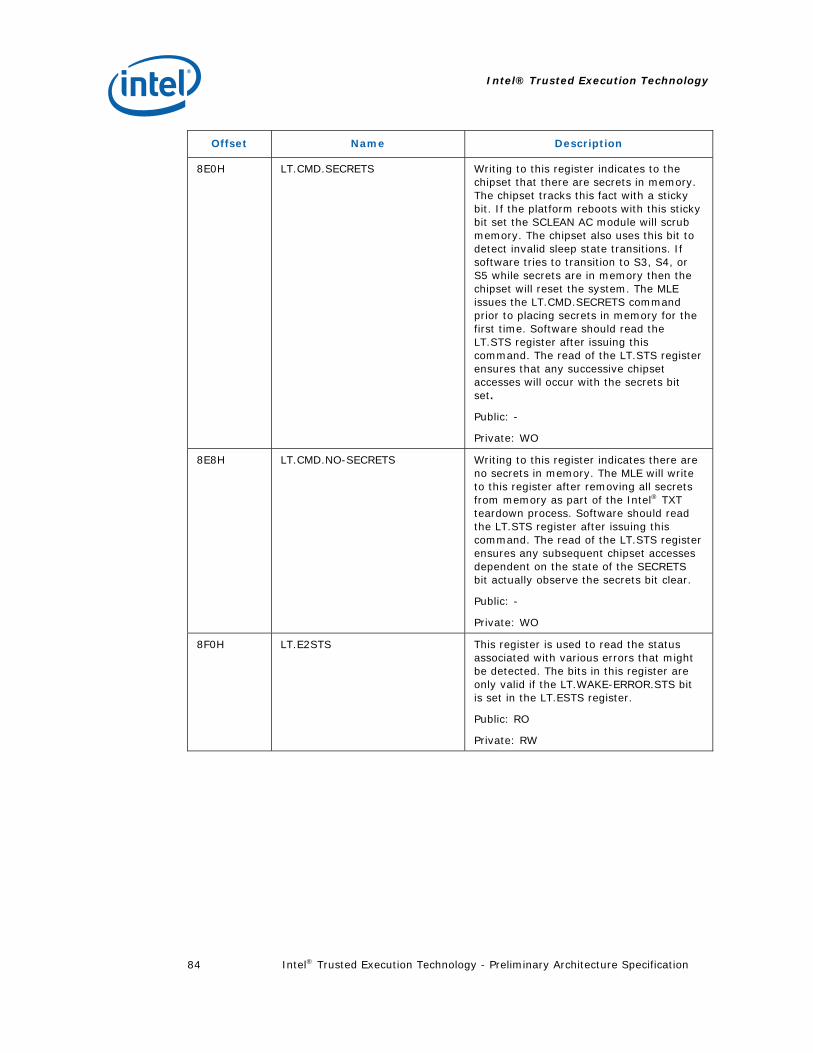
Intel® Trusted Execution Technology
Intel® Trusted Execution Technology - Preliminary Architecture Specification 84
Offset Name Description
8E0H LT.CMD.SECRETS Writing to this register indicates to the chipset that there are secrets in memory. The chipset tracks this fact with a sticky bit. If the platform reboots with this sticky bit set the SCLEAN AC module will scrub memory. The chipset also uses this bit to detect invalid sleep state transitions. If software tries to transition to S3, S4, or S5 while secrets are in memory then the chipset will reset the system. The MLE issues the LT.CMD.SECRETS command prior to placing secrets in memory for the first time. Software should read the LT.STS register after issuing this command. The read of the LT.STS register ensures that any successive chipset accesses will occur with the secrets bit set.
Public: -
Private: WO
8E8H LT.CMD.NO-SECRETS Writing to this register indicates there are no secrets in memory. The MLE will write to this register after removing all secrets from memory as part of the Intel® TXT teardown process. Software should read the LT.STS register after issuing this command. The read of the LT.STS register ensures any subsequent chipset accesses dependent on the state of the SECRETS bit actually observe the secrets bit clear.
Public: -
Private: WO
8F0H LT.E2STS This register is used to read the status associated with various errors that might be detected. The bits in this register are only valid if the LT.WAKE-ERROR.STS bit is set in the LT.ESTS register.
Public: RO
Private: RW

Intel® Trusted Execution Technology
Intel® Trusted Execution Technology - Preliminary Architecture Specification 85
Table 21. LT.STS Bit Definitions
Bit position Name Comment
0 SENTER.DONE. STS
The chipset sets this bit when it sees all of the threads have done an LT.CYC.SENTER-ACK.
When any of the threads does the LT.CYC.SEXIT-ACK the LT.THREADS.JOIN and LT.THREADS.EXISTS registers will not be equal, so the chipset will clear this bit.
1 SEXIT.DONE. STS
This bit is set when all of the bits in the LT.THREADS.JOIN register are clear. Thus, this bit will be set immediately after reset (since the bits are all 0).
Once all threads have done an LT.CYC.SEXIT-ACK, the LT.THREAD.JOIN register will be 0, so the chipset will set this bit.
3:2 Reserved Reserved
4 MEM. UNLOCK.STS
This bit will be set to 1 when the memory has been unlocked using the LT.CMD.UNLOCK-MEMORY command or after a normal reset when no measured environment was in place prior to the reset. When this bit is ‘1’, memory may be accessed by CPU cycles.
This bit will be cleared after a reset when there might have been secrets in memory before the reset.
This bit must be set if a read to 0xFED4_0000 returns a ‘1’ in bit 0.
5 BASE.LOCKED.STS
This bit will be set to 1 when the LT.CMD.LOCK.BASE command is issued.
This bit is cleared by LT.CMD.UNLOCK.BASE or by a system reset.
6 MEM-CONFIG-LOCK.STS
This bit will be set to 1 when the memory configuration has been locked.
Cleared by LT.CMD.UNLOCK.MEMCONFIG or by a system reset.
7 PRIVATE-OPEN.STS
This bit will be set to 1 when LT.CMD.OPEN-PRIVATE is performed.
Cleared by LT.CMD.CLOSE-PRIVATE or by a system reset.
10:8 Reserved Reserved

Intel® Trusted Execution Technology
Intel® Trusted Execution Technology - Preliminary Architecture Specification 86
Bit position Name Comment
11 MEM-CONFIG-OK.STS
This bit indicates whether the chipset has received and accepted the LT.CMD.MEM-CONFIG-CHECKED command. This bit is cleared by PCI reset or by the LT.CMD.UNLOCK-MEM-CONFIG command.
0: Indicates that memory configuration checking has not been performed.
1: Indicates that memory configuration checking has been performed. This bit is set to one when the chipset accepts the LT.CMD.MEM-CONFIG-CHECKED command.
Table 21 LT.DIDVID Bit Definitions
Bit position Name Comment
15:0 VID Vendor ID: 8086 for Intel® components
31:16 DID Device ID: specific to the chipset/platform
47:32 RID Revision ID: specific to the chipset/platform
63:48 ID-EXT Extended ID: specific to the chipset/platform
Table 22. LT.ERRORCODE Register Bit Format
Bit position Name Description
29:0 Type This is implementation and source specific. Provides details on the failure condition.
30 Processor/External 0 = Error condition reported by processor.
1 = Error condition reported by external software.
31 Valid/Invalid 0 = Register content invalid.
1 = Valid error.
Table 23. Type Field Encodings for Processor-Initiated Intel® TXT Shutdowns
Type Error condition Mnemonic
0 Legacy shutdown #LegacyShutdown
1-4 Reserved Reserved
5 Load memory type error in Authenticated Code Execution Area
#BadACMMType

Intel® Trusted Execution Technology
Intel® Trusted Execution Technology - Preliminary Architecture Specification 87
Type Error condition Mnemonic
6 Unrecognized AC module format #UnsupportedACM
7 Failure to authenticate #AuthenticateFail
8 Invalid AC module format #BadACMFormat
9 Unexpected snoop hit detected #UnexpectedHITM
10 Invalid event #InvalidEvent
11 Invalid MLE JOIN format #BadJOINFormat
12 Unrecoverable machine check condition
#UnrecovMCError
13 VMX abort #VMXAbort
14 Authenticated code execution area corruption
#ACMCorrupt
15 Invalid voltage/bus ratio #InvalidVIDBRatio
16 – 65535 Reserved Reserved

Intel® Trusted Execution Technology
Intel® Trusted Execution Technology - Preliminary Architecture Specification 88
B.2 TPM Platform Configuration Registers
The TPM contains Platform Configuration Registers (PCRs). The purpose of a PCR is to contain measurements. From a TPM standpoint, the TPM does not care what entity uses a PCR to store a measurement.
The TPM provides two types of PCRs: static and dynamic. Static PCRs only reset on system reset; dynamic PCRs reset upon request. Static PCRs are written by the static root of trust for measurement (SRTM). In the PC, the SRTM begins with the BIOS boot block. The dynamic PCRs are written by the dynamic root of trust for measurement (DRTM). In the PC, the DRTM is the process initiated by GETSEC[SENTER].
A PC TPM requires a minimum of 24 PCRs. The first 16 are designated the static Root of Trust and the next eight are designated the dynamic Root of Trust. Intel® TXT uses PCRs 17 and 18 within the dynamic Root of Trust to measure the MLE.
All PCRs, static or dynamic, have the same size and same updating mechanism. The size is 160 bits. This size allows the PCRs to contain a SHA-1 hash digest value. Storing a measurement value in the PCRs involves a TPM_Extend operation, which is itself a hash operation.
B.3 Intel® Trusted Execution Technology Device Space
There are several memory ranges within Intel® TXT address space provided to access Intel® TXT related devices. The first range is 0xFED4_xxxx which is divided up into 16 pages. Each page in the FED4 range has specific access attributes. A page in this region may be accessed by Intel® TXT cycles only, by Intel® TXT cycles and via private space, or by Intel® TXT cycles, private and public space.
Table 24. TPM Locality Address Mapping
Address Range TPM Locality
FED4 0xxxH Locality 0 (fully public)
FED4 1xxxH Locality 1 (trusted OS)
FED4 2xxxH Locality 2 (MLE access only)
FED4 3xxxH Locality 3 (AC modules access only)
FED4 4xxxH Locality 4 (Hardware or microcode access only)
All others Reserved
The first five pages of the 0xFED4_xxxx region are used for TPM access. Each page represents a different locality to the TPM. Locality is an attribute used by the TPM to define how it treats certain transactions. Locality is defined by the address range used for commands sent to the TPM. All Intel® TXT chipsets must support all localities. Localities 0 and 6 are considered public and accesses to these localities are accepted by the chipset under all circumstances. Accesses to locality 0 and 6 are sent to the

Intel® Trusted Execution Technology
Intel® Trusted Execution Technology - Preliminary Architecture Specification 89
ICH even if Intel® TXT is disabled, there has been no SENTER, or private space is closed. Localities 4 and 5 are never open, but may only be accessed with Intel® TXT cycles on the FSB. Localities 7 through 15 are always open from a locality perspective, but are in private space so that LT.CMD.OPEN-PRIVATE must have been done for the cycles to be sent to ICH as Intel® TXT cycles. There are Intel® TXT commands that will open localities 1 through 3. Localities 2-3 and 7-F require that both LocalityX.OPEN (localities 7-F are always open) and LT.CMD.OPEN-PRIVATE be done before allowing accesses in that range to be accepted. At reset, localities 1 through 3 are closed.
No status read check of the TPM is performed by the processor GETSEC[SENTER] instruction ahead of the TPM.HASH write sequence. If the TPM is not in acquiesced state at this time, then the PCR17-20 reset and hash registration to PCR17 may not succeed. To insure reliable system software functionality for TPM support, it is recommended that the GETSEC[SENTER] instruction only be executed once the TPM has acquiesced and ownership has been established in the context of the SENTER initiating process.

Intel® Trusted Execution Technology
Intel® Trusted Execution Technology - Preliminary Architecture Specification 90
Appendix C Intel® TXT Heap Memory
Intel® TXT Heap memory is a region of physically contiguous memory which is set aside by BIOS for the use of Intel® TXT hardware and software. The system software that launches the measured environment passes data to both the SINIT AC module and the MLE using Intel® TXT Heap memory. The system software is responsible for filling in the table contents prior to executing the SENTER instruction. An incorrect format or incorrect content of this table or tables described by this table will result in failure to launch the protected environment.
Table 25. Intel® Trusted Execution Technology Heap
Offset Length (bytes)
Name Description
0 8 BiosOsDataSize Size in bytes of the Intel® TXT specific data passed from the BIOS to system software for the purposes of launching the MLE. This size includes the number of bytes for this field, so this field cannot be less than a value of 8. Note 1.
8 BiosOsDataSize - 8
BiosOsData BIOS specific data. The format of this data is described below in Table 26.
BiosOsDataSize 8 OsMleDataSize Size in bytes of the data passed from the launching system software to the MLE. This size includes the number of bytes for this field, so this field cannot be less than a value of 8. Note 1.
BiosOsDataSize + 8
OsMleDataSize – 8
OsMleData System software -specific data. Format of data in this field is considered specific to the system software vendor.
BiosOsDataSize + OsMleDataSize
8 OsSinitDataSize Size in bytes of the data passed from the launching system software to the SINIT AC module. This size includes the number of bytes for this field, so this field cannot be less than a value of 8. Note 1.
BiosOsDataSize + OsMLEDataSize + 8
OsSinitDataSize - 8
OsSinitData System software data passed to the SINIT AC module. The format of this data is described below in Table 27.

Intel® Trusted Execution Technology
Intel® Trusted Execution Technology - Preliminary Architecture Specification 91
Offset Length (bytes)
Name Description
BiosOsDataSize + OsMleDataSize + OsSinitDataSize
8 SinitMleDataSize Size in bytes of the data passed from the launched SINIT AC module to the MLE. This size includes the number of bytes for this field, so this field cannot be less than a value of 8. Note 1.
BiosOsDataSize + OsMleDataSize + OsSinitDataSize + 8
SinitMleDataSize - 8
SinitMleData SINIT data passed to the MLE. The format of this data is described below in Table 28.
NOTES: 1. For proper data alignment on 64bit processor architectures this field must be a multiple
of 8 bytes. OsMleDataSize + OsSinitDataSize + SinitMleDataSize must be less than or equal to LT.HEAP.SIZE.
C.1 BIOS to OS Data Format
The format of the data passed from the BIOS to the system software for the purposes of launching the measured environment is shown in Table 26.
Table 26. BIOS to OS Data Table
Offset Length (bytes)
Name Description
0 4 Version Version number of the BIOS to OS data. The BiosOsData is always backwards compatible with previous versions. The current value is 0x02.
4 4 BiosSinitSize This field indicates the size of the SINIT AC module provided by system BIOS. A value of 0 indicates the BIOS is not providing a SINIT AC module for system software use. A non-0 value indicates that the AC module will be at the location specified by the LT.SINIT.BASE register and be of the specified size.
8 8 LcpPdBase Physical base address of the Platform Default Launch Control Policy, LCP_POLICY_DATA structure. Ignored if Platform Default Policy does not require additional data or does not exist.
16 8 LcpPdSize Size of the Launch Control Policy Platform Default Policy Data. Ignored if Platform Default Policy does not require additional data or does not exist.
24 4 NumLogProcs This is the total number of logical processors in the system. The minimum value in this register must be at least 1.

Intel® Trusted Execution Technology
Intel® Trusted Execution Technology - Preliminary Architecture Specification 92
C.2 OS to MLE Data Format
Each system software vendor may have a different format for this data, and any MLE being launched by system software must understand the format of that software’s handoff data.
C.3 OS to SINIT Data Format
Table 27 defines the format of the data passed from the launching system software to the SINIT AC module in the OsSinitData field.
Table 27. OS to SINIT Data Table
Offset Length (bytes)
Name Description
0 4 Version Version number of the OS to SINIT data. Current value is 0x03. This field is incremented for any change to the definition of the OsSinitData. The OsSinitData is always backwards compatible with previous versions.
4 4 Reserved Reserved for future use
8 8 MLE PageTableBase Physical address of MLE page table (the MLE page directory pointer table address)
16 8 MLE Size Size in bytes of the MLE image
24 8 MLE HeaderBase Linear address of MLE header (linear address within the MLE page tables)
32 8 PMR Low Base Physical base address of the PMR Low region (must be 2MB aligned). Can be set to zero if not desired to be enabled by SINIT. The MVMM must be loaded in one of the DPR, PRM low, or the PMR high regions.
40 8 PMR Low Size Size of the PMR Low Region (must be 2MB granular). Set to zero if not desired to be enabled by SINIT.
48 8 PMR High Base Physical base address of the PMR High region (must be 2MB aligned). Can be set to zero if not desired to be enabled by SINIT.
56 8 PMR High Size Size of the PMR HIGH Region (must be 2MB granular). Set to zero if not desired to be enabled by SINIT.
64 8 LCP PO Base Physical base address of the Platform Owner’s Launch Control Policy, LCP_POLICY_DATA structure.
72 8 LCP PO Size Size of the Launch Control Policy Platform Owner’s Policy Data.

Intel® Trusted Execution Technology
Intel® Trusted Execution Technology - Preliminary Architecture Specification 93
C.4 SINIT to MLE Data Format
Table 28 defines the format of the SINIT data presented to the MLE.
Table 28 SINIT to MLE Data Table
Offset Length (bytes)
Name Description
0 4 Version Version number of the SINIT to MLE data. Current value is 5. The SinitMleData is always backwards compatible with previous versions
4 20 BiosAcmID ID of the BIOS AC module in the system
24 4 EdxSenterFlags Value of EDX SENTER control flags
28 8 MsegValid MSEG MSR (Valid bit only)
36 20 SinitHash SHA-1 hash of the SINIT AC module
56 20 MleHash SHA-1 hash of the MLE
76 20 StmHash SHA-1 hash of STM. This is only valid if MsegValid = 1, else will contain zero
96 20 LcpPolicyHash SHA-1 Hash of the LCP policy that was enforced; if no hash is needed based on the LCP policy control field this will contain zero
116 4 PolicyControl Taken from the LCP policy used
120 8 Reserved Reserved for future use
128 4 NumberOfSinitMdrs Number of SINIT Memory Descriptor Records
132 4 SinitMdrTableOffset Pointer to the start of an array of SINIT Memory Descriptor Records as defined below. Each record describes a memory region as defined by the SINIT AC module. This field is an offset in bytes from the start of the SinitMleDataSize field.
136 4 SinitVtdDmarTableSize Length of the VT-d DMAR table pointed to by the SinitVtdDmarTable field
140 4 SinitVtdDmarTable Pointer to the start of the SINIT provided DMAR table dump for the MLE. This field is an offset in bytes from the start of the SinitMleDataSize field.

Intel® Trusted Execution Technology
Intel® Trusted Execution Technology - Preliminary Architecture Specification 94
Table 29. SINIT Memory Descriptor Record
Offset Length (bytes)
Name Description
0 8 Address Physical address of the memory range described in this record.
8 8 Length Length of the memory range. 16 1 Type Memory range type. Valid values:
0 Usable, good memory 1 SMRAM– Overlayed 2 SMRAM– Non-Overlayed 3 PCIE- PCIE Extended Config Region 4–255 Reserved
17 7 Reserved Reserved for future use
The array of Memory Descriptor Records (MDRs) is not necessarily ordered and some MDRs may be of 0 length, in which case they should be ignored.
Memory of type 0 is usable for the MLE and any code or data that it may load. SINIT will verify that the MLE and its page table are located in memory of this type.
Memory types 1 and 2 indicate regions that contain System Management Mode (SMM) code.
Memory of type 3 is the PCI Express extended configuration region. The MLE may use this to verify that the PCIE configuration specified in the ACPI tables is using the appropriate address space.

Intel® Trusted Execution Technology
Intel® Trusted Execution Technology - Preliminary Architecture Specification 95
Appendix D Intel® TXT Technology Enabling Platform
This appendix describes the Intel® TXT functionality, data structures, etc. that are unique to the Intel® TXT Technology Enabling Platform (TEP).
D.1 Data Structures
D.1.1 MLE Header
Field Offset Size (bytes)
Description
GUID 0 16 Identifies this structure
HeaderLen 16 4 Length of header in bytes
Version 20 4 Version number of this structure
EntryPoint 24 4 Linear entry point of MLE
GUID: This field contains a GUID which uniquely identifies this MLE Header Structure. The GUID is defined as follows:
ULONG GUID0; // 9082AC5A ULONG GUID1; // 74A7476F ULONG GUID2; // A2555C0F ULONG GUID3; // 42B651CB
HeaderLen: this field contains the length in bytes of the MLE Header Structure.
Version: this field contains the version of the MLE header, where the upper two bytes are the major version and the lower two bytes are the minor version. Version 1.0 (10000H) is supported for the Intel® TXT TEP.
EntryPoint: this field is the linear address, within the MLE’s linear address space, at which the ILP will begin execution upon completion of the GETSEC[SENTER] instruction.

Intel® Trusted Execution Technology
Intel® Trusted Execution Technology - Preliminary Architecture Specification 96
D.1.2 Chipset AC Module Information Table
Field Offset (Bytes)
Width (Bytes)
Description
ChipsetACMType 0x10 0x01 Module type (00h = BIOS; 01h = SINIT)
Version 0x11 0x01 Version of this table. Table versions are always backwards compatible. Version 0x01 is supported for the Intel® TXT TEP.
Length 0x12 0x02 Length of this table in bytes.
ChipsetIDList 0x14 0x04 Location of the Intel® TXT Chipset ID list used to identify Intel® TXT chipsets supported by this AC Module. This field is an offset in bytes from the start of the AC Module. See Table 18 Chipset ID List for details.
D.1.3 BIOS to OS Data
Offset Length (bytes)
Name Description
0 4 Version Version number of the BIOS to OS data. Version 0x00 is supported for the Intel® TXT TEP.
4 4 BiosSinitSize This field indicates the size of the SINIT AC module stored in system BIOS. A value of 0 indicates the system BIOS is not providing a SINIT AC module for OS use.
D.1.4 OS to SINT Data
Offset Length (bytes)
Name Description
0 4 Version Version number of the OS to SINIT data. Version 0x01 is supported for the Intel® TXT TEP.
4 4 Reserved Reserved for future use
8 8 MLE PageTableBase Physical address of MLE page table (the MLE page directory pointer table address)
16 8 MLE Size Size in bytes of the MLE image

Intel® Trusted Execution Technology
Intel® Trusted Execution Technology - Preliminary Architecture Specification 97
24 8 MLE HeaderBase Linear address of MLE header (linear address within the MLE page tables)
D.1.5 SINIT to MLE Data
Offset Length (bytes)
Name Description
0 4 Version Version number of the SINIT to MLE data. Version 0x01 is supported for the Intel® TXT TEP.
4 4 NumberOfSinitMDRs
Number of SINIT Memory Descriptor Records that follow this field.
8 24 * NumberOfSinitMDRs
SinitMDR Array of SINIT Memory Descriptor Records as defined below. Each record describes a memory region as defined by the SINIT AC module.
8+24*NumberOfSinitMDRs
20 Reserved Reserved
Opt-in MSR_Hash + 20
20 EDX_Hash Zero extended SENTER control flags
EDX_Hash + 20 20 MSEG_Valid Zero extended MSEG.Valid bit value
MSEG_Valid_Hash + 8
20 SINIT_Hash SHA-1 hash of SINIT AC module
SINIT_Hash + 20 20 MLE_Hash SHA-1 hash of MLE
MLE_Hash + 20 20 STM_Hash SHA-1 hash of STM. This is only valid if MSEG_Valid.bit = 1.
D.2 Intel® Trusted Execution Technology Configuration Registers
260H LT.NODMA.BASE This register contains the physical base address of the MPT. The value in this register is initially set by BIOS.
Public: RW
Private: RW

Intel® Trusted Execution Technology
Intel® Trusted Execution Technology - Preliminary Architecture Specification 98
268H LT.NODMA.SIZE This register contains a value which indicates the size of the MPT. The values are 0=128K, 1=256K, 2=512K, etc.
Public: RO
Private: RO
Note: On Intel® TXT TEP chipset, the MPT is fixed at 2MB and this register value is fixed at 2H (512K)
258H LT.CMD.FLUSH-WB Writing to this register flushes the chipset write buffers used to cache MPT data.
Public: -
Private: WO
The following registers are not valid on the Intel® TXT TEP: LT.CMD.OPEN.LOCALITY1, LT.CMD.CLOSE.LOCALITY1, LT.CMD.OPEN.LOCALITY2, LT.CMD.CLOSE.LOCALITY2.
In addition, the LT.CMD.SECRETS command is not fully supported (i.e. memory will not be scrubbed even if the system is reset with this flag set).
The LT.STS register will use the following bits, which are reserved on current implementations:
Bit position Name Comment
5 LT.NODMA-EN.STS
This bit will be set to 1 when the MPT is protecting main memory from bus master access.
Cleared by LT.CMD.NODMA.DIS or by a system reset.
9 LT.NODMA-CACHE.STS
Will be set to 1 when LT.CMD.NODMA-CACHE.EN is performed.
Cleared by LT.CMD.NODMA-CACHE.DIS or by a system reset.
10 LT.NODMA-TABLE-PROTECT.STS
Will be set to 1 when LT.CMD.NODMA-TABLE-PROTECT.EN is performed.
Cleared by LT.CMD.NODMA-TABLE-PROTECT.DIS or by a system reset.
D.3 MLE Page Table
Not all of the current rules regarding the MLE page tables are enforced by the Intel® TXT TEP:
• The page tables do not need to be in lower physical memory than the MLE.

Intel® Trusted Execution Technology
Intel® Trusted Execution Technology - Preliminary Architecture Specification 99
• Their may be not-present entries in the page table after the first present entry (i.e. gaps in the linear address space).
• Neither the MLE nor the page tables may overlap the memory protection table.
D.4 Memory Protection Table
This chapter describes the core logic chipset feature that protects data in the memory sub-system of a platform, as memory can be accessed by both the processor(s) and chipset.
Note: The memory protection architecture described in this chapter is unique to the Intel® TXT Technology Enabling Platform (TEP). Future platforms will have a different architecture and interface. Refer to the Intel® Virtualization Technology for Directed I/O Architecture Specification for more information on the next generation memory protection architecture.
D.4.1 Overview of DMA Page Protection
The processor, using its own protection tables, is responsible for protecting pages in memory from unauthorized access by software. The chipset is responsible for protecting some pages of memory from access by bus master devices. Pages designated as protected must not be read or written by bus masters.
The pages in memory to be protected are indicated in the Memory Protection Table (MPT). This table will cover all pages in physical memory supported by the platform.
Theoretically, the memory controller must check the MPT table for each read or write by a bus master. Such an extra check would add significant load latency on the memory I/F and degrade performance. To prevent degradation, the chipset may employ caching mechanisms to reduce the number of memory read cycles required to check MPT entries. The chipset may include a small cache that tracks pages that have been recently accessed. If I/O transactions by bus masters are linear, then the cache will have a high hit rate.
The exact number of entries required for the cache is specific to the chipset and beyond this specification’s scope. Software is required to assist with the hardware caching by issuing commands to the chipset when changing entries in the MPT. See Section 4.2 for details on the software requirements for managing the cache.
The chipset must also protect the MPT. This is necessary because a DMA device could write invalid entries to the MPT when the MPT is initialized. To prevent this type of attack, the chipset must not allow bus master writes to the MPT once the Intel® TXT launch process locks the table.
The SINIT authenticated code module must initially configure the MPT, protecting only the pages specified by the MLE page table and those corresponding to the MPT itself.

Intel® Trusted Execution Technology
Intel® Trusted Execution Technology - Preliminary Architecture Specification 100
D.4.2 Details on Chipset Memory Protection Mechanism
Once the measured environment has been established, the chipset is responsible for protecting some pages of memory from access by bus masters or by CPU accesses to the Graphics Aperture. Pages designated as “protected” must not be read or written by bus masters or by the CPU via any translation mechanism (such as the Graphics Aperture or GTT).
The pages in memory to be protected are indicated in the table called the MPT. This table has 1 bit per 4K page. A system that supports 4Gbytes of memory will require 1 Mbits for the MPT.
D.4.2.1 Overview of Chipset Cache of MPT
The chipset may include a small cache that tracks pages that have been recently accessed by bus mastering devices. If the memory transactions by the bus masters are highly linear, then this cache would have very high hit rates.
System software must maintain the cache coherency when the software changes the status of pages (protected to unprotected or unprotected to protected). System software will issue commands to the chipset to indicate that the MPT has been updated and the cache should be invalidated and reloaded.
D.4.2.2 Overview of MPT Protection Mechanism
The chipset contains a mechanism to protect the contents of the MPT from bus master device access. This is done through a separate enable command, LT.CMD.NODMA-TABLE-PROTECT.EN. The SINIT AC module will enable this protection during SMX launch. The MLE should disable this feature when tearing down the measured environment. The MLE uses the LT.CMD.NODMA-TABLE-PROTEC.DIS command to disable this feature.
D.4.3 Programming the Chipset Memory Protection Hardware
This section describes the Intel® TXT chipset memory protection mechanism and describes the proper code sequences for the MLE to manage this feature.
D.4.3.1 Enabling the Protection Mechanism
The SINIT AC module will enable the MPT and, if supported, the MPT cache. The SINIT AC module will add the following pages to the MPT before transferring control to the MLE: all pages containing the MLE image, the pages containing the MLE page tables, the pages containing the Intel® TXT device memory, and physical pages corresponding to the MPT itself. The MLE is responsible for maintaining the MPT and its associated cache. The MLE is responsible for disabling the chipset memory protection mechanism when tearing down the measured environment.

Intel® Trusted Execution Technology
Intel® Trusted Execution Technology - Preliminary Architecture Specification 101
D.4.3.2 Disabling the Protection Mechanism
The MLE must use a specific sequence when disabling the chipset’s memory protection mechanisms. This sequence is:
1. Turn off the cache of the MPT. Software does LT.CMD.NODMA-CACHE.DIS
2. Disable MPT. Software does LT.CMD.NODMA-DIS
3. Disable protection of the MPT. Software does LT.CMD.NODMA-TABLE-PROTECT.DIS
If software fails to use these sequences, the chipset may not function correctly.
The following are some general rules the software must observe when managing the Intel® TXT chipset memory protection mechanism:
1. Values in the chipset’s cache of the MPT may be undefined at reset. Software must perform an LT.CMD.CACHE.INVALIDATE before enabling the cache. The SINIT AC module will perform this step when enabling the MPT cache.
2. Software should not count on the values in the MPT to be correct after a system reset. Software must write all bits in the table to a value before the LT.CMD.NODMA-EN is performed. The SINIT AC module will ensure that the MPT memory is initialized to all ‘0’ before enabling the MPT.
3. Software may not attempt to dynamically enable or disable the MPT cache. This could result in unpredictable chipset behavior and pages in memory may not be properly protected.
4. The locations in main memory used for the MPT must be set up as uncached.
D.4.3.3 Adding a Page to the MPT
The following steps must be performed in the listed order by the MLE when adding a page to the MPT.
1. Issue LT.CMD.FLUSH-WB, causing all DMA accesses in the chipset’s write buffers to be flushed.
2. Set the corresponding bit in the chipset MPT.
3. Read the set bit to ensure success. “zero” indicates failure.
4. Issue LT.CMD.FLUSH-WB, which will cause another flush to the write cache, so that the MPT is updated.
5. Issue LT.CMD.CACHE-INVALIDATE to invalidate all cached MPT entries. The cached entries need to be invalidated because the MPT has been updated.
6. The page is now protected from accesses by bus mastering device – software may now place secrets in the page.

Intel® Trusted Execution Technology
Intel® Trusted Execution Technology - Preliminary Architecture Specification 102
D.4.3.4 Removing a Page from the MPT
The following steps must be followed by the MLE when deleting a page from the MPT. The steps must be done in the order listed.
1. Write 0’s to the entire page to remove any secrets.
2. Issue LT.CMD.FLUSH-WB, causing all DMA accesses in the chipset’s write buffers to be flushed.
3. Clear the corresponding bit in the MPT.
4. Read the cleared bit to ensure success. “one” indicates failure.
5. Issue LT.CMD.FLUSH-WB, which will cause another flush of the write cache, so that the MPT is updated.
6. Issue LT.CMD.CACHE-INVALIDATE to invalidate the old cache entries.
7. The page may now be used as a DMA buffer.