Intel S5000 Server Board Family Datasheet...Intel® S5000 Server Board Family Datasheet Intel order...
179
Intel ® S5000 Server Board Family Datasheet Intel order number D38960-006 Revision 1.3 August 31, 2007 Enterprise Platforms and Services Division
Transcript of Intel S5000 Server Board Family Datasheet...Intel® S5000 Server Board Family Datasheet Intel order...
Intel® S5000 Server Board Family Datasheet
Intel order number D38960-006
Revision 1.3
August 31, 2007
Enterprise Platforms and Services Division
Revision History Intel® S5000 Server Board Family Datasheet
Revision 1.3 Intel order number D38960-006
ii
Revision History
Date Revision Number
Modifications
31 May 06 1.1 Initial Document Release. 10 Jun 07 1.2 Revised Sections 2.3, 3.13.1, 3.4.1, 3.7; Added Sections 2.4.15, 2.4.15.1;
Updated Table 3, 26. Aug 31 07 1.3 Updated Sections 2.2.4, 3.2.1, 3.4.1, 3.4.2.3, 3.7.2.1.8; Updated Table 25 and
Figure 17
Disclaimers Information in this document is provided in connection with Intel® products. No license, express or implied, by estoppel or otherwise, to any intellectual property rights is granted by this document. Except as provided in Intel's Terms and Conditions of Sale for such products, Intel assumes no liability whatsoever, and Intel disclaims any express or implied warranty, relating to sale and/or use of Intel products including liability or warranties relating to fitness for a particular purpose, merchantability, or infringement of any patent, copyright or other intellectual property right. Intel products are not intended for use in medical, life saving, or life sustaining applications. Intel may make changes to specifications and product descriptions at any time, without notice.
Designers must not rely on the absence or characteristics of any features or instructions marked "reserved" or "undefined." Intel reserves these for future definition and shall have no responsibility whatsoever for conflicts or incompatibilities arising from future changes to them.
This document contains information on products in the design phase of development. Do not finalize a design with this information. Revised information will be published when the product is available. Verify with your local sales office that you have the latest datasheet before finalizing a design.
The Intel® S5000 Server Board Family Datasheet may contain design defects or errors known as errata which may cause the product to deviate from published specifications. Current characterized errata are available on request.
This document and the software described in it, is furnished under license and may only be used or copied in accordance with the terms of the license. The information in this manual is furnished for informational use only, is subject to change without notice, and should not be construed as a commitment by Intel Corporation. Intel Corporation assumes no responsibility or liability for any errors or inaccuracies that may appear in this document or any software that may be provided in association with this document.
Except as permitted by such license, no part of this document may be reproduced, stored in a retrieval system, or transmitted in any form or by any means without the express written consent of Intel Corporation.
Intel, Pentium, Itanium, and Xeon are trademarks or registered trademarks of Intel Corporation.
*Other brands and names may be claimed as the property of others.
Copyright © Intel Corporation 2006, 2007. All rights reserved.
Intel® S5000 Server Board Family Datasheet Table of Contents
Revision 1.3 Intel order number D38960-006
iii
Table of Contents
1. Introduction...........................................................................................................................1 1.1 Server Product References......................................................................................1 1.2 Chapter Outline ........................................................................................................1
2. Functional Architecture .......................................................................................................2 2.1 Intel® 5000 MCH Components .................................................................................4
2.1.1 Memory Controller Hub (Intel® 5000 MCH) ..............................................................4 2.1.2 Intel® 631xESB / 632xESB I/O Controller Hub (ESB2) ............................................7
2.2 Processor Sub-system ...........................................................................................11 2.2.1 Processor Support .................................................................................................12 2.2.2 Processor Population Rules...................................................................................12 2.2.3 Processor EVRD ....................................................................................................12 2.2.4 GTL2107 ................................................................................................................12 2.2.5 Common Enabling Kit (CEK) Design Support ........................................................12
2.3 Memory Sub-system ..............................................................................................13 2.3.1 Fully-buffered DIMM (FBDIMM) .............................................................................14 2.3.2 Supported Memory.................................................................................................15
2.4 I/O Sub-system ......................................................................................................17 2.4.1 PCI Sub-system .....................................................................................................17 2.4.2 Scan Order.............................................................................................................17 2.4.3 Resource Assignment ............................................................................................17 2.4.4 Automatic IRQ Assignment ....................................................................................17 2.4.5 Legacy Option ROM Support .................................................................................18 2.4.6 EFI PCI APIs ..........................................................................................................18 2.4.7 Legacy PCI APIs ....................................................................................................18 2.4.8 Dual Video..............................................................................................................18 2.4.9 Parallel ATA (PATA) Support .................................................................................18 2.4.10 Serial ATA (SATA) Support....................................................................................19 2.4.11 SATA RAID Functionality .......................................................................................20 2.4.12 Serial Attached SCSI .............................................................................................20 2.4.13 Video Controller .....................................................................................................20 2.4.14 Network Interface Controller (NIC).........................................................................20 2.4.15 Wake On LAN / Power On LAN and Magic Packet* Support.................................20
Table of Contents Intel® S5000 Server Board Family Datasheet
Revision 1.3 Intel order number D38960-006
iv
2.4.16 USB Support ..........................................................................................................21 2.4.17 Native USB Support ...............................................................................................21 2.4.18 Legacy USB Support..............................................................................................21 2.4.19 Super I/O................................................................................................................21 2.4.20 BIOS Flash.............................................................................................................22
2.5 Clock Generation and Distribution .........................................................................23 3. System BIOS .......................................................................................................................24
3.1 BIOS Identification String .......................................................................................24 3.2 Processors .............................................................................................................25
3.2.1 CPUID ....................................................................................................................25 3.2.2 Multiple Processor Initialization..............................................................................26 3.2.3 Mixed Processor Steppings ...................................................................................26 3.2.4 Mixed Processor Families ......................................................................................26 3.2.5 Mixed Processor System Bus Speeds ...................................................................26 3.2.6 Mixed Processor Cache Sizes ...............................................................................27 3.2.7 Microcode Update ..................................................................................................27 3.2.8 Processor Cache....................................................................................................27 3.2.9 Mixed Processor Configuration ..............................................................................27 3.2.10 Hyper-Threading Technology.................................................................................28 3.2.11 Intel SpeedStep® Technology ................................................................................28 3.2.12 Intel® Extended Memory 64 Technology (Intel® EM64T)........................................28 3.2.13 Execute Disable Bit Feature...................................................................................29 3.2.14 Enhanced Halt State (C1E)....................................................................................29 3.2.15 Multi-Core Processor Support ................................................................................29 3.2.16 Intel® Virtualization Technology..............................................................................30 3.2.17 Fake MSI Support ..................................................................................................30 3.2.18 Acoustical Fan Speed Control................................................................................31
3.3 Memory ..................................................................................................................32 3.3.1 Memory Sizing and Configuration ..........................................................................32 3.3.2 POST Error Codes .................................................................................................32 3.3.3 Publishing System Memory....................................................................................32 3.3.4 Mixed Speed Memory Modules..............................................................................34 3.3.5 Memory Test ..........................................................................................................34 3.3.6 Memory Scrub Engine............................................................................................35 3.3.7 Memory Map and Population Rules .......................................................................35
Intel® S5000 Server Board Family Datasheet Table of Contents
Revision 1.3 Intel order number D38960-006
v
3.3.8 Memory Modes of Operation..................................................................................38 3.3.9 Memory RAS..........................................................................................................38 3.3.10 Memory Error Handling ..........................................................................................40
3.4 Platform Control .....................................................................................................52 3.4.1 FBDIMM Open and Closed Loop Thermal Throttling .............................................53 3.4.2 Fan Speed Control .................................................................................................53
3.5 Flash ROM .............................................................................................................56 3.6 BIOS User Interface ...............................................................................................56
3.6.1 Logo / Diagnostic Screen .......................................................................................56 3.7 BIOS Setup Utility ..................................................................................................56
3.7.1 Operation ...............................................................................................................56 3.7.2 Server Platform Setup Screens..............................................................................60
3.8 Loading BIOS Defaults...........................................................................................97 3.9 Security ..................................................................................................................97
3.9.1 Operating Model.....................................................................................................97 3.9.2 Password Protection ..............................................................................................98 3.9.3 Password Clear Jumper.........................................................................................98
3.10 BIOS Update Flash Procedures.............................................................................98 3.10.1 Intel Iflash32 BIOS Update Utility...........................................................................98 3.10.2 Intel® One Boot Flash Update Utility ......................................................................99
3.11 BIOS Bank Select and One Boot Flash Update...................................................101 3.11.1 BIOS Bank Select Jumper in Normal Mode (Jumper Pins 2 - 3 connected) ........101 3.11.2 BIOS Bank Select Jumper in Recovery Mode (Jumper pins 1 - 2 connected).....102
3.12 OEM Binary..........................................................................................................102 3.12.1 Splash Logo .........................................................................................................102
3.13 Boot Device Selection ..........................................................................................102 3.13.1 USB Boot Device Reordering...............................................................................103 3.13.2 Server Managment Boot Device Control..............................................................103
3.14 Operating System Support ...................................................................................103 3.14.1 Windows Compatibility .........................................................................................103 3.14.2 Advanced Configuration and Power Interface (ACPI) ..........................................104
3.15 Front Control Panel Support ................................................................................104 3.15.1 Power Button........................................................................................................104 3.15.2 Reset Button ........................................................................................................105 3.15.3 Non-Maskable Interrupt (NMI) Button ..................................................................105
Table of Contents Intel® S5000 Server Board Family Datasheet
Revision 1.3 Intel order number D38960-006
vi
3.16 Sleep and Wake Support .....................................................................................105 3.16.1 System Sleep States............................................................................................105 3.16.2 Wake Events / SCI Sources.................................................................................106
3.17 Non-Maskable Interrupt Handling ........................................................................106 3.18 BIOS Server Management ...................................................................................106 3.19 IPMI......................................................................................................................106 3.20 Console Redirection.............................................................................................107
3.20.1 Serial Configuration Settings................................................................................107 3.20.2 Keystroke Mappings.............................................................................................107 3.20.3 Limitations ............................................................................................................108 3.20.4 Interface to Server Management..........................................................................108
3.21 IPMI Serial Interface.............................................................................................108 3.21.1 Channel Access Modes .......................................................................................108 3.21.2 Interaction with BIOS Console Redirection ..........................................................108
3.22 Wired For Management (WFM)............................................................................109 3.22.1 PXE BIOS Support ...............................................................................................109
3.23 System Management BIOS (SMBIOS) ................................................................109 4. System Management ........................................................................................................111
4.1 Feature Support ...................................................................................................111 4.1.1 Legacy Features ..................................................................................................111 4.1.2 New Features.......................................................................................................113
4.2 Power System ......................................................................................................113 4.3 BMC Reset Control ..............................................................................................115
4.3.1 BMC Exits Firmware Update Mode......................................................................115 4.4 System Initialization .............................................................................................115
4.4.1 Fault Resilient Booting (FRB)...............................................................................115 4.5 Integrated Front Panel User Interface..................................................................117
4.5.1 Power LED ...........................................................................................................117 4.5.2 System Status LED ..............................................................................................117 4.5.3 Chassis ID LED....................................................................................................119 4.5.4 Front Panel / Chassis Inputs ................................................................................119 4.5.5 Front Panel Lock-out Operation ...........................................................................120
4.6 Private Management I2C Buses ..........................................................................121 4.7 Watchdog Timer...................................................................................................121
Intel® S5000 Server Board Family Datasheet Table of Contents
Revision 1.3 Intel order number D38960-006
vii
4.8 System Event Log (SEL)......................................................................................121 4.8.1 Servicing Events ..................................................................................................122 4.8.2 SEL Erasure.........................................................................................................122 4.8.3 Timestamp Clock .................................................................................................122
4.9 Sensor Data Record (SDR) Repository................................................................123 4.9.1 Initialization Agent ................................................................................................123
4.10 Field Replaceable Unit (FRU) Inventory Device...................................................123 4.11 Diagnostics and Beep Code Generation..............................................................124 4.12 NMI.......................................................................................................................124
4.12.1 Signal Generation ................................................................................................125 4.13 Processor Sensors...............................................................................................125
4.13.1 Processor Status Sensors....................................................................................126 4.13.2 Processor VRD Over-Temperature Sensor..........................................................126 4.13.3 ThermTrip Monitoring...........................................................................................127 4.13.4 Platform Enviroment Control Interface (PECI) Support........................................127 4.13.5 PROCHOT Support..............................................................................................127 4.13.6 IERR Monitoring...................................................................................................128 4.13.7 Dynamic Processor Voltage Monitoring ...............................................................128 4.13.8 Processor Temperature Monitoring......................................................................128 4.13.9 Processor Thermal Control Monitoring (Prochot).................................................129 4.13.10 CPU Population Error Sensor ..............................................................................129
4.14 Standard Fan Management .................................................................................129 4.14.1 Nominal Fan Speed .............................................................................................130 4.14.2 Stepwise Linear....................................................................................................130 4.14.3 Clamp...................................................................................................................131 4.14.4 Sleep State Fan Control .......................................................................................132 4.14.5 Fan Redundancy Detection..................................................................................132 4.14.6 Hot Swap Fan Support .........................................................................................132
4.15 Acoustic Management..........................................................................................132 4.15.1 Fan Profiles ..........................................................................................................132 4.15.2 Interactions with DIMM Thermal Management.....................................................132
4.16 PSMI Support .......................................................................................................133 4.17 System Memory RAS and Bus Error Monitoring ..................................................133
4.17.1 SMI Timeout Sensor ............................................................................................133 4.17.2 Memory Sensor....................................................................................................133
Table of Contents Intel® S5000 Server Board Family Datasheet
Revision 1.3 Intel order number D38960-006
viii
4.17.3 Critical Interrupt Sensor .......................................................................................134 4.17.4 DIMM Status Sensors ..........................................................................................134 4.17.5 System Memory Redundancy Monitoring ............................................................135 4.17.6 System Memory Monitoring and System Boot .....................................................138
4.18 PCI Express* Support ..........................................................................................138 4.18.1 PCI Express Link Sensors ...................................................................................138 4.18.2 BMC Self-test .......................................................................................................138
4.19 Field Replaceable Unit (FRU) / Fault LED Control...............................................139 4.20 Hot-swap Backplane (HSBP) Support .................................................................139 4.21 Intel® Remote Management Module (Intel® RMM) Support .................................139
4.21.1 Discovery Sequence ............................................................................................139 4.21.2 Division of Network Traffic ...................................................................................140 4.21.3 Event Forwarding .................................................................................................140 4.21.4 Serial Routing.......................................................................................................141 4.21.5 Messaging Interfaces ...........................................................................................141
4.22 Channel Management..........................................................................................142 4.23 User Model...........................................................................................................142 4.24 Session Support...................................................................................................142 4.25 Media Bridging .....................................................................................................142 4.26 Host to BMC Communication Interface................................................................143
4.26.1 LPC / KCS Interface.............................................................................................143 4.26.2 Receive Message Queue.....................................................................................143 4.26.3 Server Management Software (SMS) Interface ...................................................143 4.26.4 SMM Interface......................................................................................................143
4.27 IPMB Communication Interface ...........................................................................144 4.27.1 PCI System Management Bus (SMBus) ..............................................................144
4.27.2 BMC as I2C Master Controller on IPMB ...............................................................144
4.27.3 IPMB LUN Routing...............................................................................................145 4.28 Emergency Management Port (EMP) Interface ...................................................147
4.28.1 COM2 Port Switching...........................................................................................147 4.28.2 Basic Mode ..........................................................................................................147 4.28.3 Terminal Mode .....................................................................................................147 4.28.4 Invalid Password Handling...................................................................................149 4.28.5 Serial Ping Message Behavior .............................................................................149
4.29 LAN Interface .......................................................................................................150
Intel® S5000 Server Board Family Datasheet Table of Contents
Revision 1.3 Intel order number D38960-006
ix
4.29.1 IPMI 1.5 Messaging .............................................................................................150 4.29.2 IPMI 2.0 Messaging .............................................................................................151 4.29.3 Intel® 631xESB / 632xESB I/O Controller Hub Embedded LAN Channels ..........152 4.29.4 Address Resolution Protocol Support ..................................................................152 4.29.5 Internet Control Message Protocol Support .........................................................152 4.29.6 Serial-over-LAN (SOL) 2.0 ...................................................................................152
5. Error Reporting and Handling .........................................................................................153 5.1 Fault Resilient Booting (FRB)...............................................................................153
5.1.1 BSP POST Failures (FRB-2)................................................................................153 5.1.2 Operating System Load Failures (OS Boot Timer)...............................................153
5.2 Error Handling and Logging .................................................................................154 5.2.1 Error Sources and Types .....................................................................................154 5.2.2 Error Logging via SMI Handler .............................................................................154 5.2.3 Timestamp Clock Event .......................................................................................155
5.3 Error Messages and Error Codes ........................................................................156 5.3.1 Diagnostic LEDs...................................................................................................156 5.3.2 POST Code Checkpoints .....................................................................................157 5.3.3 POST Error Messages and Handling...................................................................160 5.3.4 POST Error Beep Codes......................................................................................162 5.3.5 POST Error Pause Option....................................................................................162
Glossary ...................................................................................................................................163 Reference Documents ............................................................................................................166
List of Figures Intel® S5000 Server Board Family Datasheet
Revision 1.3 Intel order number D38960-006
x
List of Figures
Figure 1. Intel® 5000 MCH Functional Architechture.....................................................................3 Figure 2. CEK Processor Mounting.............................................................................................13 Figure 3. FBD Topology ..............................................................................................................15 Figure 4. Identifying Banks of Memory........................................................................................16 Figure 5. General BIOS Screen Display Layout ..........................................................................57 Figure 6. Setup Utility — Main Screen Display ...........................................................................61 Figure 7. Setup Utility — Advanced Screen Display ...................................................................64 Figure 8. Setup Utility — Processor Configuration Screen Display.............................................65 Figure 9. Setup Utility — Specific Processor Information Screen Display ..................................67 Figure 10. Setup Utility — Memory Configuration Screen Display..............................................69 Figure 11. Setup Utility — Memory RAS and Performance Configuration Screen Display .........71 Figure 12. Setup Utility — ATA Controller Configuration Screen Display ...................................73 Figure 13. Setup Utility — Mass Storage Configuration Screen Display.....................................76 Figure 14. Setup Utility — Serial Port Configuration Screen Display ..........................................77 Figure 15. Setup Utility — USB Controller Configuration Screen Display...................................79 Figure 16. Setup Utility — PCI Configuration Screen Display.....................................................81 Figure 17. Setup Utility — System Acoustic and Performance Configuration Screen Display....83 Figure 18. Setup Utility — Security Configuration Screen Display..............................................85 Figure 19. Setup Utility — Server Management Configuration Screen Display ..........................87 Figure 20. Setup Utility — Console Redirection Screen Display.................................................89 Figure 21. Setup Utility — Server Management System Information Screen Display.................90 Figure 22. Setup Utility — Setup Utility – Boot Options Screen Display .....................................92 Figure 23. Setup Utility — Setup Utility – Boot Manager Screen Display....................................94 Figure 24. Setup Utility — Error Manager Screen Display ..........................................................95 Figure 25. Setup Utility — Exit Screen Display ...........................................................................96 Figure 26. Intel® 631xESB / 632xESB I/O Controller Hub Power / Reset Signals ....................114 Figure 27. DIMM Grouping........................................................................................................135 Figure 28. BMC IPMB Message Reception...............................................................................146 Figure 29. Location of Diagnostic LEDs on Server Board.........................................................157
Intel® S5000 Server Board Family Datasheet List of Tables
Revision 1.3 Intel order number D38960-006
xi
List of Tables Table 1. DIMM Module Capacities ..............................................................................................16 Table 2. NIC2 Status LED ...........................................................................................................20 Table 3. Supported Processor Configurations ............................................................................25 Table 4. Mixed Processor Configurations ...................................................................................27 Table 5. Memory Errors Captured by Error Manager ..................................................................45 Table 6. DIMM Fault Indicator LEDs ...........................................................................................45 Table 7. System Status Indicator LEDs.......................................................................................46 Table 8. NMI Generation .............................................................................................................47 Table 9. Mirroring Mode Errors ...................................................................................................47 Table 10. POST Memory Error Handling.....................................................................................48 Table 11. Runtime Memory Error Handling, No Redundancy .....................................................49 Table 12. Runtime Error Handling, with Redundancy .................................................................50 Table 13. BIOS Setup Page Layout ............................................................................................58 Table 14. BIOS Setup: Keyboard Command Bar ........................................................................59 Table 15. Setup Utility — Main Screen Fields.............................................................................62 Table 16. Setup Utility — Processor Configuration Screen Fields ..............................................65 Table 17. Setup Utility — Specific Processor Information Screen Fields....................................68 Table 18. Setup Utility — Memory Configuration Screen Fields .................................................69 Table 19. Setup Utility — Memory RAS and Performance Configuration Screen Fields ............71 Table 20. Setup Utility — ATA Controller Configuration Screen Fields.......................................74 Table 21. Setup Utility — Mass Storage Configuration Screen Fields ........................................76 Table 22. Setup Utility — Serial Ports Configuration Screen Fields............................................78 Table 23. Setup Utility — USB Controller Configuration Screen Fields ......................................79 Table 24. Setup Utility — PCI Configuration Screen Fields ........................................................82 Table 25. Setup Utility — System Acoustic and Performance Configuration Screen Fields .......84 Table 26. Setup Utility — Security Configuration Screen Fields .................................................86 Table 27. Setup Utility — Server Management Configuration Screen Fields..............................87 Table 28. Setup Utility — Console Redirection Configuration Fields ..........................................89 Table 29. Setup Utility — Server Management System Information Fields.................................91 Table 30. Setup Utility — Setup Utility – Boot Options Screen Display ......................................93 Table 31. Setup Utility — Setup Utility – Boot Manager Screen Display.....................................94 Table 32. Setup Utility — Error Manager Screen Fields .............................................................95 Table 33. Setup Utility — Exit Screen Fields...............................................................................96
List of Tables Intel® S5000 Server Board Family Datasheet
Revision 1.3 Intel order number D38960-006
xii
Table 34. Security Features Operating Model.............................................................................98 Table 35. NMI Error Messages .................................................................................................106 Table 36. Console Redirection Escape Sequences for Headless Operation ............................108 Table 37. BMC Reset Sources and Actions ..............................................................................115 Table 38. Power LED Indicator States ......................................................................................117 Table 39. System Status LED Indicator States .........................................................................118 Table 40. Chassis ID LED Indicator States ...............................................................................119 Table 41. Secure Mode versus ACPI State...............................................................................121 Table 42. BMC Beep Codes......................................................................................................124 Table 43. Processor Sensors ....................................................................................................125 Table 44. Requirements for Processor Status ..........................................................................126 Table 45. Standard Channel Assignments................................................................................142 Table 46. Keyboard Controller Style Interfaces.........................................................................143 Table 47. BMC IPMB LUN Routing ...........................................................................................145 Table 48. Terminal Mode Commands .......................................................................................148 Table 49. Supported RMCP+ Cipher Suites..............................................................................151 Table 50. Supported RMCP+ Payload Types ...........................................................................151 Table 51. POST Progress Code LED Example.........................................................................156 Table 52. POST Code Checkpoints ..........................................................................................157 Table 53. POST Error Messages and Handling ........................................................................160 Table 54. POST Error Beep Codes...........................................................................................162
Intel® S5000 Server Board Family Datasheet Introduction
Revision 1.3 Intel order number D38960-006
1
1. Introduction This datasheet provides information about features and regulatory information that is common to Intel® server boards and Intel® workstation boards that use the Intel® 5000 Series Chipset. This is a companion document to the technical product specifications that are available for each server or workstation board that uses the Intel® 5000 MCH. To fully understand all features of a particular server or workstation board that uses this chipset, you need to use both this datasheet and the technical product specification that is available for your server board or workstation board.
The target audience for this document is anyone wishing to obtain more in depth detail of the server board or workstation board than that which is available in the User’s Guide or the board-specific technical product specification. This is a technical document that is meant to assist people with understanding and learning more about the specific features of the board.
1.1 Server Product References This document applies to both specific Intel® server boards and to specific Intel® workstation boards. Unless otherwise noted, all references to “Intel boards” or “board” apply to both server boards and workstation boards that use this chipset.
1.2 Chapter Outline This document is divided into the following chapters
Chapter 1 - Introduction Chapter 2 - Functional Architecture Chapter 3 - System BIOS Chapter 4 - System Management Chapter 5 - Error Reporting and Handling
Functional Architecture Intel® S5000 Server Board Family Datasheet
Revision 1.3 Intel order number D38960-006
2
2. Functional Architecture This chapter provides a detailed description of the functionality associated with the architectural blocks that comprise the Intel® 5000 MCH. A diagram of the chipset functional architecture is on the following page.
Intel® S5000 Server Board Family Datasheet Functional Architecture
Revision 1.3 Intel order number D38960-006
3
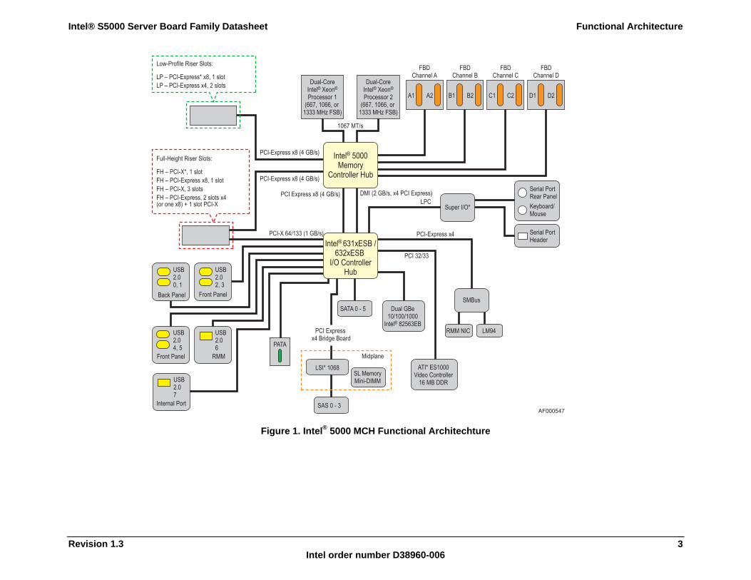
Figure 1. Intel® 5000 MCH Functional Architechture
Functional Architecture Intel® S5000 Server Board Family Datasheet
Revision 1.3 Intel order number D38960-006
4
2.1 Intel® 5000 MCH Components The chipsets consist of two components that together are responsible for providing the interface between all major sub-systems found on the Intel® server or workstation board. These sub-systems include the processor, memory, and I/O sub-systems. These components are:
Intel® 5000 Memory Controller Hub (Intel® 5000 MCH) Intel® Enterprise South Bridge 2 (Intel® 631xESB / 632xESB I/O Controller Hub)
The following sub-sections provide an overview of the primary functions and supported features of each chipset component used on the Intel® boards that utilize the Intel® 5000 MCH. Later sections in this chapter provide more detail on how each sub-system is implemented.
Note: See the Intel® server board or workstation board technical product specification that applies to your product for feature-specific support information.
2.1.1 Memory Controller Hub (Intel® 5000 MCH) The Intel® 5000 MCH is a 1432-ball FC-BGA package configured to support the following interfaces:
CPU dual, independent system bus at 667-, 1066-, or 1333-MHz operation. Four fully-buffered DIMM (FBD) channels supporting fully-buffered DDR2 DIMMs
(FBDIMMs), 24-lane serial bus at 4.25 GB/s (533 MT/s) and 5.3 GB/s (667 MT/s) peak theoretical bandwidth per channel. This allows a total of 17 GB/s and 21 GB/s peak theoretical bandwidth for all four Channels combined.
One PCI Express* x8 port with an aggregate bandwidth of 4 GB/s interface to the Intel® 631xESB / 632xESB I/O Controller Hub.
One PCI Express x8 port with an aggregate bandwidth of 4 GB/s interface to x8 PCI Express Connector.
One PCI Express x8 port with an aggregate bandwidth of 4 GB/s interface to x8 PCI Express Connector.
One PCI Express x4 ESI port with an aggregate bandwidth of 2 GB/s interface to the Intel® 631xESB / 632xESB I/O Controller Hub.
2.1.1.1 System Bus The Intel® 5000 MCH supports either single- or dual-processor configurations using the Intel® Xeon® 5000 Sequence processor with a 2x 2 MB cache. The Intel® 5000 MCH supports a base system bus frequency of 266 MHz and 333 MHz for Intel® 5000 Series Chipsets. The address and request interface is double-pumped to 533 MHz, and the 64-bit data interface (+ parity) is quad-pumped to 1066 MHz. This provides a matched system bus address and data bandwidths of 8.5 GB/s.
Intel® S5000 Server Board Family Datasheet Functional Architecture
Revision 1.3 Intel order number D38960-006
5
2.1.1.2 Intel® 5000 MCH Memory Sub-System Overview The Intel® 5000 MCH provides an integrated memory controller for direct connection to four channels of registered fully-buffered DIMM (FBD) DDR2 533/667 MHz memory (stacked or unstacked). Peak theoretical memory data bandwidth using FBD 533/667 MHz technology is 17 and 21.3 GB/s, respectively.
When all four memory channels are populated and operating, they function in lock-step mode. The maximum supported FBD DDR2 533/667 MHz memory configuration is 64 GB.
The Intel® 5000 MCH memory interface provides several reliability, availability, serviceability, usability, and manageability (RASUM) features, including:
Memory mirroring allows two copies of all data in the memory subsystem (one on each channel) to be maintained.
Memory sparing allows one DIMM per channel to be held in reserve and brought on-line if another FBDIMM in the channel becomes defective.
Hardware periodic memory scrubbing, including demand scrub support. Retry on uncorrectable memory errors. Intel® x4/x8 Single Device Data Correction (SDDC) for memory error detection and
correction of any number of bit failures in a single x4/x8 memory device.
Note: Memory sparing and memory mirroring are mutually exclusive.
2.1.1.3 PCI Express* Interface The Intel® 5000 MCH supports the PCI Express* high-speed serial I/O interface for superior I/O bandwidth. The scalable PCI Express interface of the Intel® 5000 MCH complies with the PCI Express Interface Specification, Revision 1.0a.
The Intel® 5000 MCH provides three x8 PCI Express* interfaces, each with a maximum theoretical bandwidth of 4.2 GB/s. Each of these x8 PCI Express interfaces may alternatively be configured as two independent x4 PCI Express interfaces. A PCI Express interface/port is defined as a collection of lanes. Each lane (x1) consists of two striped differential pairs in each direction (transmit and receive). The raw bit-rate on the data pins of 2.5 Gb/s, results in a real bandwidth of 250 MB/s per pair, given the 8/10 bit encoding used to transmit data across this interface.
The Intel® 5000 MCH is a root-class component as defined in the PCI Express Interface Specification. The PCI Express* interfaces of the Intel® 5000 MCH support connections to a variety of bridges and devices that are compliant with the same revision of the specification.
2.1.1.3.1 PCI Express* Training To establish a connection between PCI Express* endpoints, the endpoints participate in a sequence of steps called training. This sequence establishes the operational width of the link and adjusts skews of the various lanes within a link so that the data sample points can correctly take a data sample from the link.
Functional Architecture Intel® S5000 Server Board Family Datasheet
Revision 1.3 Intel order number D38960-006
6
In the case of a x8 port, the x4 link-pairs first attempt to train independently, and will collapse to a single link at the x8 width upon detection of a single device returning link ID information upstream. Once the number of links has been established, they negotiate to train at the highest common width, and step down in its supported link widths to succeed in training. The result may be that the link has trained as a x1 link.
Although the bandwidth of this link size is substantially lower than a x8 link or a x4 link, it allows communication between the two devices. Software can then interrogate the device at the other end of the link to determine why it failed to train at a higher width. This would not be possible without support for the x1 link width.
Width negotiation is done only during training or retraining, not during recovery.
2.1.1.3.2 PCI Express* Retry The PCI Express* interface incorporates a link-level retry mechanism. The hardware detects a corrupted transmission packet and performs a retry of that packet and all following packets. Although this causes a temporary interruption in the delivery of packets, the retry helps to maintain the link integrity.
2.1.1.3.3 PCI Express* Link Recovery If excessive errors occur, the hardware can determine that the quality of the connection is in question and the end points can enter a quick training sequence, known as recovery. The width of the connection will not be renegotiated, but the adjustment of skew between lanes of the link might occur. This occurs without any software intervention, but the software might be notified.
2.1.1.3.4 PCI Express* Data Protection The PCI Express* high-speed serial interface uses traditional CRC protection. The data packets use a 32-bit CRC protection scheme, the same CRC-32 used by Ethernet. The smaller link packets use a 16-bit CRC scheme. Since packets utilize 8B/10B encoding, and not all encodings are used; this provides further data protection, as illegal codes can be detected. If errors are detected on the reception of data packets due to various transients, these data packets can be retransmitted. Hardware logic supports this link-level retry without software intervention.
Intel® S5000 Server Board Family Datasheet Functional Architecture
Revision 1.3 Intel order number D38960-006
7
2.1.1.3.5 PCI Express* Retrain If the hardware is unable to perform a successful recovery, then the link automatically reverts to the polling state and initiates a full retraining sequence. This is a drastic event with an implicit reset to the downstream device and all subordinate devices, and is logged by the Intel® 5000 MCH as a "Link Down" error. If escalation of this event is enabled, software is notified of the link DL_DOWN condition. If software is involved, then data is probably lost, and processes need to be restarted. This is preferred over the taking down the system or going offline for an extended time.
2.1.1.4 Enterprise South Bridge Interface (ESI) A PCI interface is provided for a connection to the memory controller hub (Intel® 5000 MCH). Maximum realized bandwidth on this interface is 2 GB/s in each direction simultaneously, for an aggregate of 4 GB/s. This PCI Express* interface is compliant with the PCI Express Base Specification Revision 1.0a, and supports x4 and x8 bandwidths.
2.1.2 Intel® 631xESB / 632xESB I/O Controller Hub (ESB2) The Intel® 631xESB / 632xESB I/O Controller Hub is a multi-function device that provides an upstream hub interface for access to several embedded I/O functions and features, including:
Compliant with the PCI Express Base Specification, Revision 1.0a, with support for four PCI Express* root ports (module-based hot-plug support) and two 1x4 downstream ports (connector-based hot-swap support)
Compliant with the PCI-X Addendum to the PCI Local Bus Specification, Revision 1.0b Compliant with the PCI Local Bus Specification, Revision 2.3 with support for 33 MHz
PCI operations Compliant with the PCI Standard Hot-Plug Controller and Subsystem Specification,
Revision 1.0 ACPI 2.0 power management logic support Enhanced DMA controller, interrupt controller, and timer functions Integrated IDE controller with support for Ultra ATA100 / 66 / 33 Integrated SATA controller Baseboard management controller (BMC) USB host interface with support for eight USB 2.0 ports; via four UHCI host controllers;
and one EHCI high-speed host controller Compliant with the System Management Bus (SMBus) Specification, Version 2.0 with
additional support for I2C devices Support for the Audio Codec ‘97, Revision 2.3 Specification Low pin count (LPC) interface
Each function within the Intel® 631xESB / 632xESB I/O Controller Hub has its own set of configuration registers. Once configured, each appears to the system as a distinct hardware controller that shares the same PCI bus interface.
Functional Architecture Intel® S5000 Server Board Family Datasheet
Revision 1.3 Intel order number D38960-006
8
2.1.2.1 PCI Interface The Intel® 631xESB / 632xESB I/O Controller Hub PCI interface supports a 33-MHz, Revision 2.3-compliant implementation. All PCI signals are 5-V tolerant, except for PME#. An integrated PCI arbiter supports up to six external PCI bus masters in addition to the internal Intel® 631xESB / 632xESB I/O Controller Hub requests. On Intel® boards that use the Intel® 5000 MCH, this PCI interface is used to support one on-board PCI device: the ATI* ES1000 video controller.
2.1.2.2 PCI Express* Interface The Intel® 631xESB / 632xESB I/O Controller Hub provides PCI Express* root ports that are compliant with the PCI Express Base Specification Revision 1.0a. The PCI Express root ports can be statically configured as four x1 ports or ganged together to form one x4 port. Each root port supports 250 MB/s bandwidth in each direction (500 MB/s concurrent).
The Intel® 631xESB / 632xESB I/O Controller Hub implements two x4 downstream ports. The maximum realized bandwidth on this interface is 1 GB/s in each direction simultaneously, for an aggregate of 2 GB/s. These two ports can be configured as one x8 PCI Express* port. This PCI Express interface is compliant with the PCI Express Base Specification Revision 1.0a.
2.1.2.3 PCI-X* Bus Interface The Intel® 631xESB / 632xESB I/O Controller Hub provides a PCI-X* bus interface that supports conventional PCI and PCI-X Mode 1. The PCI-X interfaces on the Intel® 631xESB / 632xESB I/O Controller Hub are compliant with the following:
“PCI-X Addendum” to the PCI Local Bus Specification Revision 1.0b “Mode 1” sections of the “PCI-X Electrical and Mechanical Addendum” to the PCI Local
Bus Specification Revision 2.0a “PCI-X Protocol Addendum” to the PCI Local Bus Specification Revision 2.0a
The Intel® 631xESB / 632xESB I/O Controller Hub supports PCI bus frequencies of 66 MHz, 100 MHz, and 133 MHz.
2.1.2.4 IDE Interface (Bus Master Capability and Synchronous DMA Mode) The Intel® 631xESB / 632xESB I/O Controller Hub has an integrated IDE controller with an independent IDE signal channel that supports up to two IDE devices. This integrated functionality provides the interface for IDE hard disks and ATAPI devices. Each IDE device can have independent timings. The IDE interface supports PIO IDE transfers of up to 16 MB/s and Ultra ATA transfers of up 100 MB/s. The IDE interface integrates 16x32-bit buffers for optimal transfers and does not consume any ISA DMA resources. The IDE signal channels in the Intel® 631xESB / 632xESB I/O Controller Hub can be configured to primary and secondary channels.
Intel® S5000 Server Board Family Datasheet Functional Architecture
Revision 1.3 Intel order number D38960-006
9
2.1.2.5 Serial ATA (SATA) Host Controller The SATA host controller supports a combination of up to six SATA or four serial attached SCSI (SAS) devices. This provides an interface for SATA hard disks and ATAPI devices. The SATA interface supports PIO IDE transfers up to 16 MB/s and Serial ATA transfers up to 3.0 Gb/s (300 MB/s).
The SATA system for the Intel® 631xESB / 632xESB I/O Controller Hub contains six independent SATA signal ports that can be independently electrically isolated. Each SATA device can have independent timings. They can be configured to the standard primary and secondary channels. In addition, the controller hub offers the Intel® Embedded Server RAID Technology that enables data striping (RAID Level 0) for higher-performance or data mirroring (RAID Level 1) for fault-tolerance between the two SATA drives, alleviating disk bottlenecks by taking advantage of the dual, independent SATA controllers integrated in the Intel® 631xESB / 632xESB I/O Controller Hub.
Note: See the Intel® server board or workstation board technical product specification that applies to your product for more information.
2.1.2.6 Baseboard Management Controller (BMC) The BMC component of the Intel® 631xESB / 632xESB I/O Controller Hub is provided by an embedded ARC* controller and associated peripheral functionality that is used to provide the baseboard management controller functionality that is required for IPMI-based server management. The following is a summary of the Intel® 631xESB / 632xESB I/O Controller Hub management hardware features utilized by the BMC:
ARC4 processor with 16 Kb I-cache and D-cache 256 Kb of internal SRAM with dual port (one for code accesses and one for all other
accesses). Expansion bus, allowing connection to external Flash PROM (asynchronous or
synchronous), an external SRAM or an external SDRAM. Serial flash interface Five SMB ports, two that support FML (either master or slave) RS-232 serial port (UART) Cryptographic module, supporting AES and RC4 encryption algorithms and SHA1 and
MD5 authentication algorithms with internal DMA and raw checksum support. Two keyboard controller style (KCS) interfaces residing on the LPC bus General-purpose input/output (GPIO) interface MAC CSR interface Timer interface Host DMA interface
Functional Architecture Intel® S5000 Server Board Family Datasheet
Revision 1.3 Intel order number D38960-006
10
2.1.2.7 Low Pin Count (LPC) Interface The Intel® 631xESB / 632xESB I/O Controller Hub implements an LPC Interface as described in the Low Pin Count Interface Specification, Revision 1.1. The low pin count (LPC) bridge function of the Intel® 631xESB / 632xESB I/O Controller Hub resides in PCI Device 31: Function 0. In addition to the LPC bridge interface function, D31:F0 contains other functional units including DMA, interrupt controllers, timers, power management, system management, GPIO, and RTC.
2.1.2.8 Compatibility Modules (DMA Controller, Timer/Counters, Interrupt Controller)
The DMA controller incorporates the logic of two 82C37 DMA controllers, with seven independently programmable channels. Channels 0–3 are hardwired to 8-bit, count-by-byte transfers, and channels 5 through 7 are hardwired to 16-bit, count-by-word transfers. Any two of the seven DMA channels can be programmed to support fast Type-F transfers.
The Intel® 631xESB / 632xESB I/O Controller Hub supports LPC DMA. LPC DMA and PC/PCI DMA use the Intel® 631xESB / 632xESB I/O Controller Hub’s DMA controller. LPC DMA is handled through the use of the LDRQ# lines from peripherals and special encoding on LAD[3:0] from the host. Single, demand, verify, and increment modes are supported on the LPC interface. Channels 0–3 are 8 bit channels. Channels 5 through 7 are 16-bit channels. Channel 4 is reserved as a generic bus master request.
The timer / counter block contains three counters that are equivalent in function to those found in one 82C54 programmable interval timer. These three counters are combined to provide the system timer function, and speaker tone. The 14.31818-MHz oscillator input provides the clock source for these three counters.
The Intel® 631xESB / 632xESB I/O Controller Hub provides an ISA-compatible programmable interrupt controller (PIC) that incorporates the functionality of two 82C59 interrupt controllers. The two interrupt controllers are cascaded so that 14 external and two internal interrupts are possible. In addition, the I/O Controller Hub supports a serial interrupt scheme. All of the registers in these modules can be read and restored. This is required to save and restore the system state after power has been removed and restored to the platform.
2.1.2.9 Advanced Programmable Interrupt Controller (APIC) In addition to the standard ISA-compatible PIC described in the previous section, the Intel® 631xESB / 632xESB I/O Controller Hub incorporates the Advanced Programmable Interrupt Controller (APIC).
2.1.2.10 Universal Serial Bus (USB) Controller The Intel® 631xESB / 632xESB I/O Controller Hub contains an enhanced host controller interface that supports USB high-speed signaling. High-speed USB 2.0 allows data transfers up to 480 Mb/s, which is 40 times faster than full-speed USB. The I/O Controller Hub also contains four universal host controller interface (UHCI) controllers that support USB full-speed and low-speed signaling.
The Intel® 631xESB / 632xESB I/O Controller Hub supports eight USB 2.0 ports. All eight ports capable of high-speed, full-speed, and low-speed.
Intel® S5000 Server Board Family Datasheet Functional Architecture
Revision 1.3 Intel order number D38960-006
11
2.1.2.11 Real-time Clock (RTC) The Intel® 631xESB / 632xESB I/O Controller Hub contains a Motorola* MC146818A-compatible real-time clock with 256 bytes of battery-backed RAM. The real-time clock performs two key functions: keeping track of the time of day and storing system data, even when the system is powered down. The RTC operates on a 32.768-KHz crystal and a separate 3-V lithium battery.
The RTC supports two lockable memory ranges. By setting bits in the configuration space, two 8-byte ranges can be locked to read and write accesses. This prevents unauthorized reading of passwords or other system security information.
2.1.2.12 General-purpose Input/Output (GPIO) General-purpose inputs and outputs are provided for custom system designs. The number of inputs and outputs depends on the Intel® 631xESB / 632xESB I/O Controller Hub configuration. All unused GPI pins must be pulled high or low, so they are at a predefined level and do not cause problems.
Note: See the Intel® server board or workstation board technical product specification that applies to your product for more information.
2.1.2.13 System Management Bus (SMBus 2.0) The Intel® 631xESB / 632xESB I/O Controller Hub contains a SMBus host interface that allows the processor to communicate with SMBus slaves. This interface is compatible with most I2C devices. Special I2C commands are implemented. The SMBus host controller for the I/O Controller Hub provides a mechanism for the processor to initiate communications with SMBus peripherals (slaves).
The Intel® 631xESB / 632xESB I/O Controller Hub supports slave functionality, including the Host Notify protocol. The host controller supports eight command protocols of the SMBus interface: Quick Command, Send Byte, Receive Byte, Write Byte/Word, Read Byte/Word, Process Call, Block Read/Write, and Host Notify.
See the System Management Bus (SMBus) Specification, Version 2.0 for more information.
2.2 Processor Sub-system The support circuitry for the processor sub-system consists of the following:
Dual LGA771 zero insertion force (ZIF) processor sockets Processor host bus AGTL+ support circuitry Reset configuration logic Processor module presence detection logic BSEL detection capabilities CPU signal level translation Common enabling kit (CEK) CPU retention support
Functional Architecture Intel® S5000 Server Board Family Datasheet
Revision 1.3 Intel order number D38960-006
12
2.2.1 Processor Support Intel® boards that use the Intel® 5000 MCH support one or two Intel® Xeon® 5000 sequence
processors that utilize a 667, 1066, or 1333 MHz system bus with frequencies starting at 3.67 GHz. Previous generations of the Intel® Xeon® processors are not supported on these boards.
2.2.2 Processor Population Rules When two processors are installed, both must be of identical revision, core voltage, and bus/core speed. When only one processor is installed, it must be in the socket labeled CPU1. The other socket must be empty.
Processors must be populated in sequential order. Processor socket 1 (CPU1) must be populated before processor socket 2 (CPU2). No terminator is required in the second processor socket when using a single processor configuration.
The board is designed to provide up to 130 A of current per processor. Processors with higher current requirements are not supported.
2.2.3 Processor EVRD EVRD11.0, Enterprise Voltage Regulator Down, is a DC-to-DC converter that meets the processor power requirements server platform. Processors supported by this VR are: Intel® 5000 sequence processors and future processor technologies
EVRD11.0 incorporates functional changes from prior EVRD design guidelines.
2.2.4 GTL2107 The GTL2107 is a customized translator between dual Intel® Xeon® 5000 sequence processors, system health management, Intel® 631xESB / 632xESB I/O Controller Hub, and power supply LVTTL and GTL signals. The GTL2107 is a 12-bit translator to interface between the 3.3-V LVTTL chipset I/O and the Multi-Core Intel® Xeon® 5000 processor sequence processor GTL- / GTL / GTL+ I/O. The device is designed for platform health management in dual-processor applications.
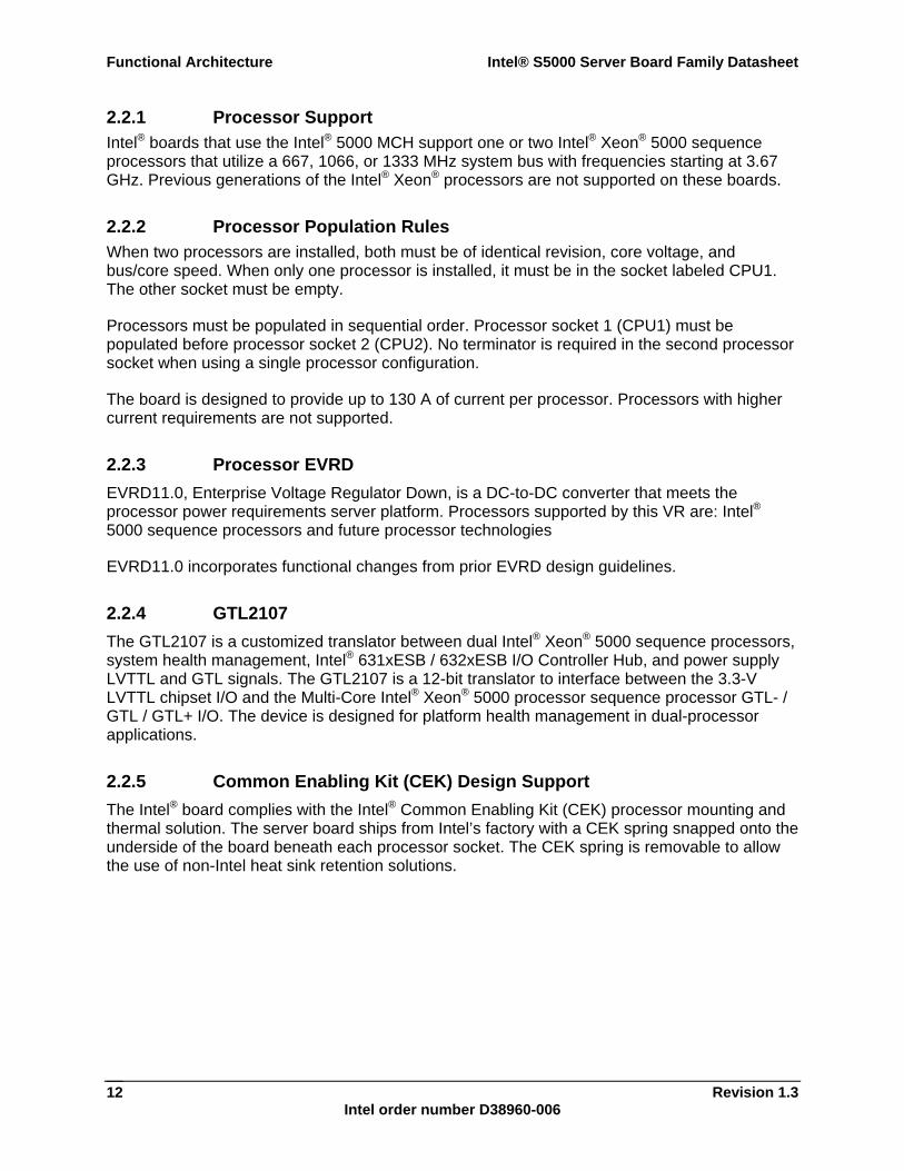
2.2.5 Common Enabling Kit (CEK) Design Support The Intel® board complies with the Intel® Common Enabling Kit (CEK) processor mounting and thermal solution. The server board ships from Intel’s factory with a CEK spring snapped onto the underside of the board beneath each processor socket. The CEK spring is removable to allow the use of non-Intel heat sink retention solutions.
Intel® S5000 Server Board Family Datasheet Functional Architecture
Revision 1.3 Intel order number D38960-006
13
TP02091
Heatsink assembly
Thermal InterfaceMaterial (TIM)
Server Board
CEK Spring
Chassis
AF000196
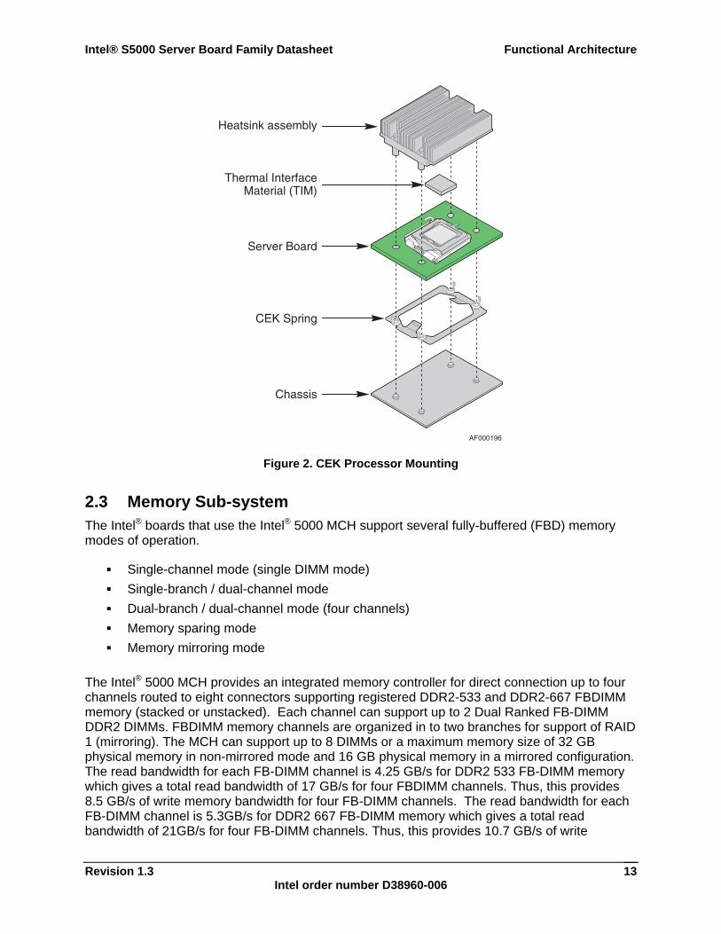
Figure 2. CEK Processor Mounting
2.3 Memory Sub-system The Intel® boards that use the Intel® 5000 MCH support several fully-buffered (FBD) memory modes of operation.
Single-channel mode (single DIMM mode) Single-branch / dual-channel mode Dual-branch / dual-channel mode (four channels) Memory sparing mode Memory mirroring mode
The Intel® 5000 MCH provides an integrated memory controller for direct connection up to four channels routed to eight connectors supporting registered DDR2-533 and DDR2-667 FBDIMM memory (stacked or unstacked). Each channel can support up to 2 Dual Ranked FB-DIMM DDR2 DIMMs. FBDIMM memory channels are organized in to two branches for support of RAID 1 (mirroring). The MCH can support up to 8 DIMMs or a maximum memory size of 32 GB physical memory in non-mirrored mode and 16 GB physical memory in a mirrored configuration. The read bandwidth for each FB-DIMM channel is 4.25 GB/s for DDR2 533 FB-DIMM memory which gives a total read bandwidth of 17 GB/s for four FBDIMM channels. Thus, this provides 8.5 GB/s of write memory bandwidth for four FB-DIMM channels. The read bandwidth for each FB-DIMM channel is 5.3GB/s for DDR2 667 FB-DIMM memory which gives a total read bandwidth of 21GB/s for four FB-DIMM channels. Thus, this provides 10.7 GB/s of write
Functional Architecture Intel® S5000 Server Board Family Datasheet
Revision 1.3 Intel order number D38960-006
14
memory bandwidth for four FB-DIMM channels. The total bandwidth is based on read bandwidth thus the total bandwidth is 17 GB/s for 533 and 21.0 GB/s for 667.
A pair of channels is a branch. Branch 0 consists of channel A and channel B, Branch 1 consists of channel C and channel D. A DIMM can have two ranks; a channel supports a maximum of eight ranks.
In non-mirrored operation, the two DDR2 channels within a branch operate in lock-step and the branches operate independently. When memory mirroring is configured, the channels operate in lock-step under normal conditions, but independently under failure and recovery conditions.
The Intel® 5000 MCH supports a burst length of four in either single-channel mode or dual-channel mode. In dual-channel mode this results in eight 64-bit chunks (64-byte cache line) from a single read or write. In single-channel mode, two reads or writes are required to access a cache line of data.
Memory between 32 GB, and 32 GB minus 512 MB, is not accessible for use by the operating system and may be lost to the user. This area is reserved for the BIOS, APIC configuration space, PCI adapter interface, and virtual video memory space. This means that if 32 GB of memory is installed, 31.5 GB of this memory is usable. The chipset should allow the remapping of unused memory above the 32 GB address, but this memory may not be accessible to an operating system that has a 32 GB memory limit.
To boot the system, the system BIOS uses a dedicated I2C bus to retrieve DIMM information needed to program the Intel® 5000 MCH memory registers.
2.3.1 Fully-buffered DIMM (FBDIMM) The fully-buffered DIMM (FBDIMM) memory interface provides a high-bandwidth, large-capacity channel solution that has a narrow host interface. FBDIMMs use commodity DRAMs isolated from the channel behind an advanced memory buffer (AMB) on the DIMM that allows a greater number of devices per channel without loading the interconnect and affecting performance. Memory capacity remains at a maximum of 36 devices per DIMM and total memory capacity scales with DRAM bit density.
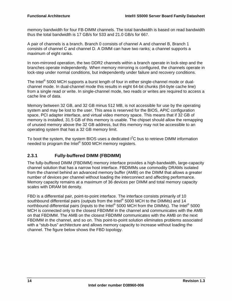
FBD is a differential pair, point-to-point interface. The interface consists primarily of 10 southbound differential pairs (outputs from the Intel® 5000 MCH to the DIMMs) and 14 northbound differential pairs (inputs to the Intel® 5000 MCH from the DIMMs). The Intel® 5000 MCH is connected only to the closest FBDIMM in the channel and communicates with the AMB on that FBDIMM. The AMB on the closest FBDIMM communicates with the AMB on the next FBDIMM in the channel, and so on. This point-to-point solution eliminates problems associated with a “stub-bus” architecture and allows memory capacity to increase without loading the channel. The figure below shows the FBD topology.
Intel® S5000 Server Board Family Datasheet Functional Architecture
Revision 1.3 Intel order number D38960-006
15
Figure 3. FBD Topology
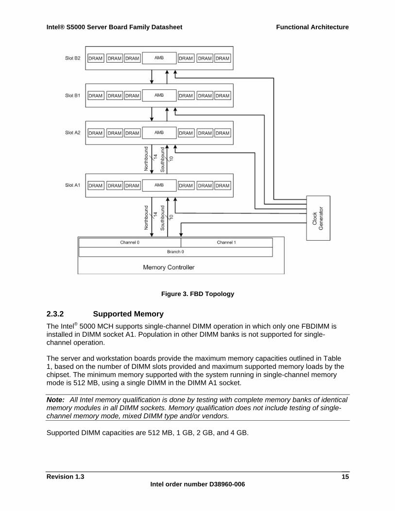
2.3.2 Supported Memory The Intel® 5000 MCH supports single-channel DIMM operation in which only one FBDIMM is installed in DIMM socket A1. Population in other DIMM banks is not supported for single-channel operation.
The server and workstation boards provide the maximum memory capacities outlined in Table 1, based on the number of DIMM slots provided and maximum supported memory loads by the chipset. The minimum memory supported with the system running in single-channel memory mode is 512 MB, using a single DIMM in the DIMM A1 socket.
Note: All Intel memory qualification is done by testing with complete memory banks of identical memory modules in all DIMM sockets. Memory qualification does not include testing of single-channel memory mode, mixed DIMM type and/or vendors.
Supported DIMM capacities are 512 MB, 1 GB, 2 GB, and 4 GB.
Functional Architecture Intel® S5000 Server Board Family Datasheet
Revision 1.3 Intel order number D38960-006
16
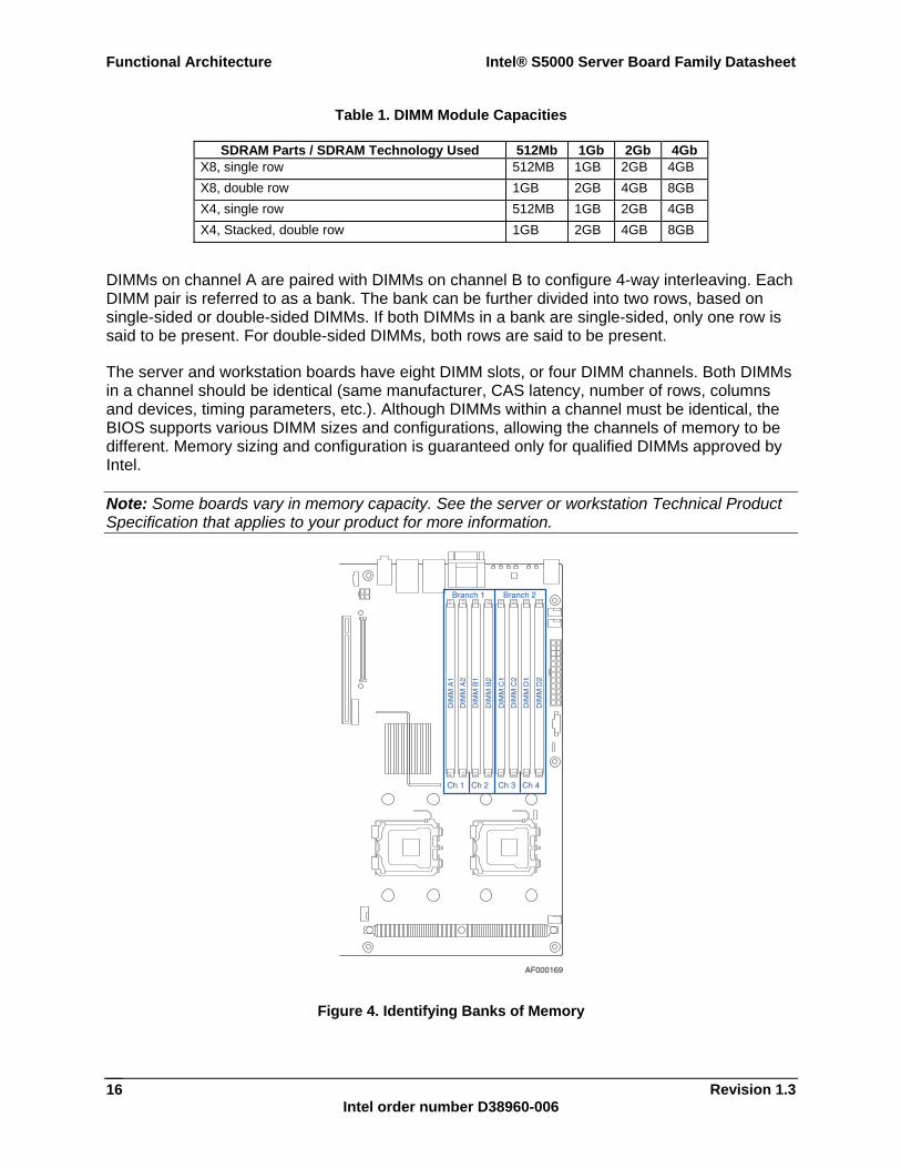
Table 1. DIMM Module Capacities
SDRAM Parts / SDRAM Technology Used 512Mb 1Gb 2Gb 4Gb X8, single row 512MB 1GB 2GB 4GB X8, double row 1GB 2GB 4GB 8GB X4, single row 512MB 1GB 2GB 4GB X4, Stacked, double row 1GB 2GB 4GB 8GB
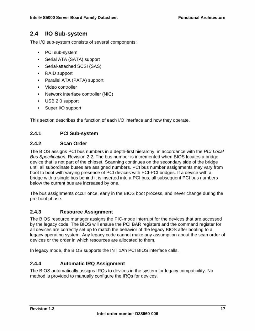
DIMMs on channel A are paired with DIMMs on channel B to configure 4-way interleaving. Each DIMM pair is referred to as a bank. The bank can be further divided into two rows, based on single-sided or double-sided DIMMs. If both DIMMs in a bank are single-sided, only one row is said to be present. For double-sided DIMMs, both rows are said to be present.
The server and workstation boards have eight DIMM slots, or four DIMM channels. Both DIMMs in a channel should be identical (same manufacturer, CAS latency, number of rows, columns and devices, timing parameters, etc.). Although DIMMs within a channel must be identical, the BIOS supports various DIMM sizes and configurations, allowing the channels of memory to be different. Memory sizing and configuration is guaranteed only for qualified DIMMs approved by Intel.
Note: Some boards vary in memory capacity. See the server or workstation Technical Product Specification that applies to your product for more information.
AF000169
Branch 1 Branch 2
Ch 1 Ch 2 Ch 3 Ch 4
DIM
M A
1
DIM
M A
2
DIM
M B
1
DIM
M B
2
DIM
M C
1
DIM
M C
2
DIM
M D
1
DIM
M D
2
Figure 4. Identifying Banks of Memory
Intel® S5000 Server Board Family Datasheet Functional Architecture
Revision 1.3 Intel order number D38960-006
17
2.4 I/O Sub-system The I/O sub-system consists of several components:
PCI sub-system Serial ATA (SATA) support Serial-attached SCSI (SAS) RAID support Parallel ATA (PATA) support Video controller Network interface controller (NIC) USB 2.0 support Super I/O support
This section describes the function of each I/O interface and how they operate.
2.4.1 PCI Sub-system
2.4.2 Scan Order The BIOS assigns PCI bus numbers in a depth-first hierarchy, in accordance with the PCI Local Bus Specification, Revision 2.2. The bus number is incremented when BIOS locates a bridge device that is not part of the chipset. Scanning continues on the secondary side of the bridge until all subordinate buses are assigned numbers. PCI bus number assignments may vary from boot to boot with varying presence of PCI devices with PCI-PCI bridges. If a device with a bridge with a single bus behind it is inserted into a PCI bus, all subsequent PCI bus numbers below the current bus are increased by one.
The bus assignments occur once, early in the BIOS boot process, and never change during the pre-boot phase.
2.4.3 Resource Assignment The BIOS resource manager assigns the PIC-mode interrupt for the devices that are accessed by the legacy code. The BIOS will ensure the PCI BAR registers and the command register for all devices are correctly set up to match the behavior of the legacy BIOS after booting to a legacy operating system. Any legacy code cannot make any assumption about the scan order of devices or the order in which resources are allocated to them.
In legacy mode, the BIOS supports the INT 1Ah PCI BIOS interface calls.
2.4.4 Automatic IRQ Assignment The BIOS automatically assigns IRQs to devices in the system for legacy compatibility. No method is provided to manually configure the IRQs for devices.
Functional Architecture Intel® S5000 Server Board Family Datasheet
Revision 1.3 Intel order number D38960-006
18
2.4.5 Legacy Option ROM Support The legacy support code in the BIOS will dispatch the legacy option ROMs in the available memory space in the address range 0C0000h-0DFFFFh and will follow all the legacy rules with respect to the option ROM space. If room is available in the E segment, and both C and D segments are already used, the BIOS will also shadow up to 0E7FFF. The BIOS allows the user to disable the shadowing of the onboard PCI devices.
2.4.6 EFI PCI APIs The BIOS provides standard PCI protocols as described in the Extensible Firmware Interface Reference Specification, Version 1.1.
2.4.7 Legacy PCI APIs In legacy mode, the system BIOS will support the INT 1Ah, AH = B1h functions as defined in the PCI BIOS Specification, Revision 2.1. The system BIOS supports the real mode interface.
2.4.8 Dual Video The BIOS supports single and dual video modes. Dual video mode is disabled by default.
In single video mode, the onboard video controller is disabled when an add-in video card is detected.
In dual video mode, the onboard video controller is enabled and is the primary video device. The external video card is allocated resources and is considered the secondary video device.
Note: See the server or workstation Technical Product Specification that applies to your product for more information.
2.4.9 Parallel ATA (PATA) Support The integrated IDE controller of the Intel® 631xESB / 632xESB I/O Controller Hub ICH6 provides one IDE channel. This IDE channel can support one optical drive. The IDE channels can be configured and enabled or disabled by accessing the BIOS Setup Utility during POST.
The BIOS supports the ATA/ATAPI Specification, version 6. It initializes the embedded IDE controller in the chipset south-bridge and the IDE devices that are connected to these devices. The BIOS scans the IDE devices and programs the controller and the devices with their optimum timings. The IDE disk read/write services that are provided by the BIOS use PIO mode, but the BIOS will program the necessary Ultra DMA registers in the IDE controller so that the operating system can use the Ultra DMA modes.
The BIOS initializes and supports ATAPI devices such as LS-120/240, CD-ROM, CD-RW, and DVD-ROM drives.
Intel® S5000 Server Board Family Datasheet Functional Architecture
Revision 1.3 Intel order number D38960-006
19
2.4.9.1 Ultra ATA/100 The IDE interface of the Intel® 631xESB / 632xESB I/O Controller Hub ICH DMA protocol redefines signals on the IDE cable to allow both host and target throttling of data and transfer rates of up to 100 MB/s.
2.4.9.2 IDE Initialization The BIOS supports the ATA/ATAPI Specification, version 6. The BIOS initializes the embedded IDE controller in the chipset (Intel® 631xESB / 632xESB I/O Controller Hub) and the IDE device that is connected to this device. The BIOS scans the IDE device and programs the controller and the device with their optimum timings. The IDE disk read/write services that are provided by the BIOS use PIO mode, but the BIOS programs the necessary Ultra DMA registers in the IDE controller so the operating system can use the Ultra DMA modes.
2.4.10 Serial ATA (SATA) Support The integrated Serial ATA (SATA) controller of the Intel® 631xESB / 632xESB I/O Controller Hub provides up to six SATA or four SAS devices ports on the server board. The SATA ports can be enabled / disabled and/or configured through the BIOS Setup Utility.
The BIOS initializes and supports SATA devices just like PATA devices. It initializes the embedded IDE controllers in the chipset and any SATA devices that are connected to these controllers. From a software standpoint, SATA controllers present the same register interface as PATA controllers. Hot-plugging SATA drives during the boot process is not supported by the BIOS and may result in undefined behavior.
The SATA function in the Intel® 631xESB / 632xESB I/O Controller Hub has dual modes of operation to support different operating system conditions. In the case of native IDE-enabled operating systems, the Intel® 631xESB / 632xESB I/O Controller Hub has separate PCI functions for serial and parallel ATA. To support legacy operating systems, there is only one PCI function for both the serial and parallel ATA ports.
The MAP register provides the ability to share PCI functions. When sharing is enabled, all I/O decoding is done through the SATA registers. A software write to the Function Disable Register (D31, F0, offset F2h, bit 1) causes Device 31, Function 1 (IDE controller) to be hidden and its configuration registers are not used. The SATA Capability Pointer Register (offset 34h) will change to indicate that Message Signaled Interrupt (MSI) is not supported in combined mode.
The Intel® 631xESB / 632xESB I/O Controller Hub SATA controller features two sets of interface signals that can be independently enabled or disabled. Each interface is supported by an independent DMA controller. The Intel® 631xESB / 632xESB I/O Controller Hub SATA controller interacts with an attached mass storage device through a register interface that is equivalent to that which is presented by a traditional IDE host adapter. The host software follows existing standards and conventions when accessing the register interface and follows standard command protocol conventions.
SATA interface transfer rates are independent of UDMA mode settings. SATA interface transfer rates will operate at the bus’s maximum speed, regardless of the UDMA mode reported by the SATA device or the system BIOS.
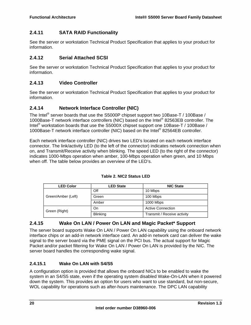
Functional Architecture Intel® S5000 Server Board Family Datasheet
Revision 1.3 Intel order number D38960-006
20
2.4.11 SATA RAID Functionality
See the server or workstation Technical Product Specification that applies to your product for information.
2.4.12 Serial Attached SCSI
See the server or workstation Technical Product Specification that applies to your product for information.
2.4.13 Video Controller
See the server or workstation Technical Product Specification that applies to your product for information.
2.4.14 Network Interface Controller (NIC) The Intel® server boards that use the S5000P chipset support two 10Base-T / 100Base / 1000Base-T network interface controllers (NIC) based on the Intel® 82563EB controller. The Intel® workstation boards that use the S5000X chipset support one 10Base-T / 100Base / 1000Base-T network interface controller (NIC) based on the Intel® 82564EB controller.
Each network interface controller (NIC) drives two LED’s located on each network interface connector. The link/activity LED (to the left of the connector) indicates network connection when on, and Transmit/Receive activity when blinking. The speed LED (to the right of the connector) indicates 1000-Mbps operation when amber, 100-Mbps operation when green, and 10 Mbps when off. The table below provides an overview of the LED’s.
Table 2. NIC2 Status LED
LED Color LED State NIC State Off 10 Mbps Green 100 Mbps Green/Amber (Left) Amber 1000 Mbps On Active Connection
Green (Right) Blinking Transmit / Receive activity
2.4.15 Wake On LAN / Power On LAN and Magic Packet* Support The server board supports Wake On LAN / Power On LAN capability using the onboard network interface chips or an add-in network interface card. An add-in network card can deliver the wake signal to the server board via the PME signal on the PCI bus. The actual support for Magic Packet and/or packet filtering for Wake On LAN / Power On LAN is provided by the NIC. The server board handles the corresponding wake signal.
2.4.15.1 Wake On LAN with S4/S5 A configuration option is provided that allows the onboard NICs to be enabled to wake the system in an S4/S5 state, even if the operating system disabled Wake-On-LAN when it powered down the system. This provides an option for users who want to use standard, but non-secure, WOL capability for operations such as after-hours maintenance. The DPC LAN capability
Intel® S5000 Server Board Family Datasheet Functional Architecture
Revision 1.3 Intel order number D38960-006
21
provides a secure system power-up, plus the ability to provide BIOS boot options, by sending authenticated IPMI messages directly to the BMC via the onboard NICs.
2.4.16 USB Support The USB controller functionality integrated into the Intel® 631xESB / 632xESB I/O Controller Hub ICH6 provides the server board with the interface for up to eight USB 2.0 ports. One internal USB 2.0 port is provided to support a USB internal floppy disk drive. One internal 1x10 header is provided to support an additional two optional USB 2.0 ports. USB 2.0 ports are routed through the bridge board connector for optional front access.
2.4.17 Native USB Support During the power on self-test (POST), the BIOS initializes and configures the USB subsystem in accordance with chapter 14 of the Extensible Firmware Interface Reference Specification, Version 1.1. The BIOS is capable of initializing and using the following types of USB devices:
USB Specification-compliant keyboards USB Specification-compliant mice USB Specification-compliant storage devices that utilize bulk-only transport mechanism
USB devices are scanned to determine if they are required for booting.
The BIOS supports USB 1.1-compliant devices and host controllers. The BIOS configures the USB 2.0-compliant host controller and USB 2.0-compliant devices in USB 1.1 mode because all USB 2.0 devices are required to support USB 1.1 mode. Although USB 1.1 mode is slower than USB 2.0 mode, the difference in speed is not significant during the pre-boot phase. The operating system can reconfigure the USB devices in USB 2.0 mode as required. The BIOS configures the USB 2.0 host controller (EHCI) so the operating system can use it.
During the pre-boot phase, the BIOS automatically supports the hot addition and hot removal of USB devices. For example, if a USB device is hot plugged, the BIOS detects the device insertion, initializes the device, and makes it available to the user. Only onboard USB controllers are initialized by BIOS. This does not prevent the operating system from supporting any available USB controllers, including on add-in cards.
2.4.18 Legacy USB Support The BIOS supports PS/2* emulation of USB keyboards and mice. During POST, the BIOS initializes and configures the root hub ports and then searches for a keyboard, a mouse, and the USB hub then enables them.
2.4.19 Super I/O Legacy I/O support is provided by a National Semiconductor* PC87427 Super I/O device. This chip contains the necessary circuitry to control two serial ports and PS/2-compatible keyboard and mouse. The Intel® server and workstation boards that use this chipset support the following:
GPIOs
Functional Architecture Intel® S5000 Server Board Family Datasheet
Revision 1.3 Intel order number D38960-006
22
Two serial ports Removable media drives Keyboard and mouse support Wake up control System health support
2.4.19.1 General Purpose Input/Output (GPIO) The National Semiconductor* PC87427 Super I/O provides nine general-purpose input/output pins that the server and workstation boards utilize.
Note: See the server or workstation Technical Product Specification that applies to your product for information.
2.4.19.2 Removable Media Drives The BIOS supports removable media devices in accordance with the Tested Hardware and Operating System List. The BIOS supports booting from USB mass storage devices connected to the chassis USB port, such as a USB flash drive device. The BIOS supports USB 2.0 media storage devices that are backward compatible to the USB 1.1 specification.
2.4.19.3 Keyboard and Mouse Dual stacked PS/2* ports on the back edge of the server board support a keyboard and mouse. Either port can support a mouse or keyboard. Neither port supports hot plugging, or connector insertion, while the system is turned on.
The system can boot without a keyboard or mouse attached. If present, the BIOS will detect the keyboard during POST and displays the message “Keyboard Detected” on the POST screen.
2.4.19.4 Wake-up Control The Super I/O contains functionality that allows various events to control the power-on and power-off the system.
Note See the server or workstation Technical Product Specification that applies to your product for information.
2.4.20 BIOS Flash The BIOS supports the Intel® 28F320C3B flash part. The flash part is a 4 MB flash ROM, of which 2 MB is programmable. The flash ROM contains system initialization routines, a setup utility, and runtime support routines. The layout is subject to change, as determined by Intel.
The flash ROM contains the necessary drivers for onboard peripherals such as SCSI, Ethernet, and video controllers. The Flash Memory Update utility loads the BIOS image into the flash.
Intel® S5000 Server Board Family Datasheet Functional Architecture
Revision 1.3 Intel order number D38960-006
23
2.5 Clock Generation and Distribution All buses on the Intel® server and workstation boards that use the Intel® 5000 MCH operate using synchronous clocks. Clock synthesizer/driver circuitry on the server board generates clock frequencies and voltage levels as required, including the following:
200-MHz differential clock at 0.7V logic levels. For processor 1, processor 2, debug port, and the Intel® 5000 MCH.
100-MHz differential clock at 0.7V logic levels on CK409B. For the DB800 clock buffer. 100-MHz differential clock at 0.7 Vlogic levels on DB800. For the PCI Express* device
this is the Intel® 5000 MCH, which includes x4 PCI Express slot. For SATA this is the Intel® 631xESB / 632xESB I/O Controller Hub ICH6.
66 MHz at 3.3V logic levels: for 5000 North Bridge and the Intel® 631xESB / 632xESB I/O Controller Hub ICH6.
48 MHz at 3.3V logic levels: for Intel® 631xESB / 632xESB I/O Controller Hub ICH6 and SIO.
33 MHz at 3.3V logic levels: for the Intel® 631xESB / 632xESB I/O Controller Hub ICH6, video, BMC, and SIO.
14.318 MHz at 2.5V logic levels: For the Intel® 631xESB / 632xESB I/O Controller Hub ICH6 and video.
10 Mhz at 5V logic levels: For the BMC.
The PCI-X slot speed on the full-length riser card is determined by the riser card in use.
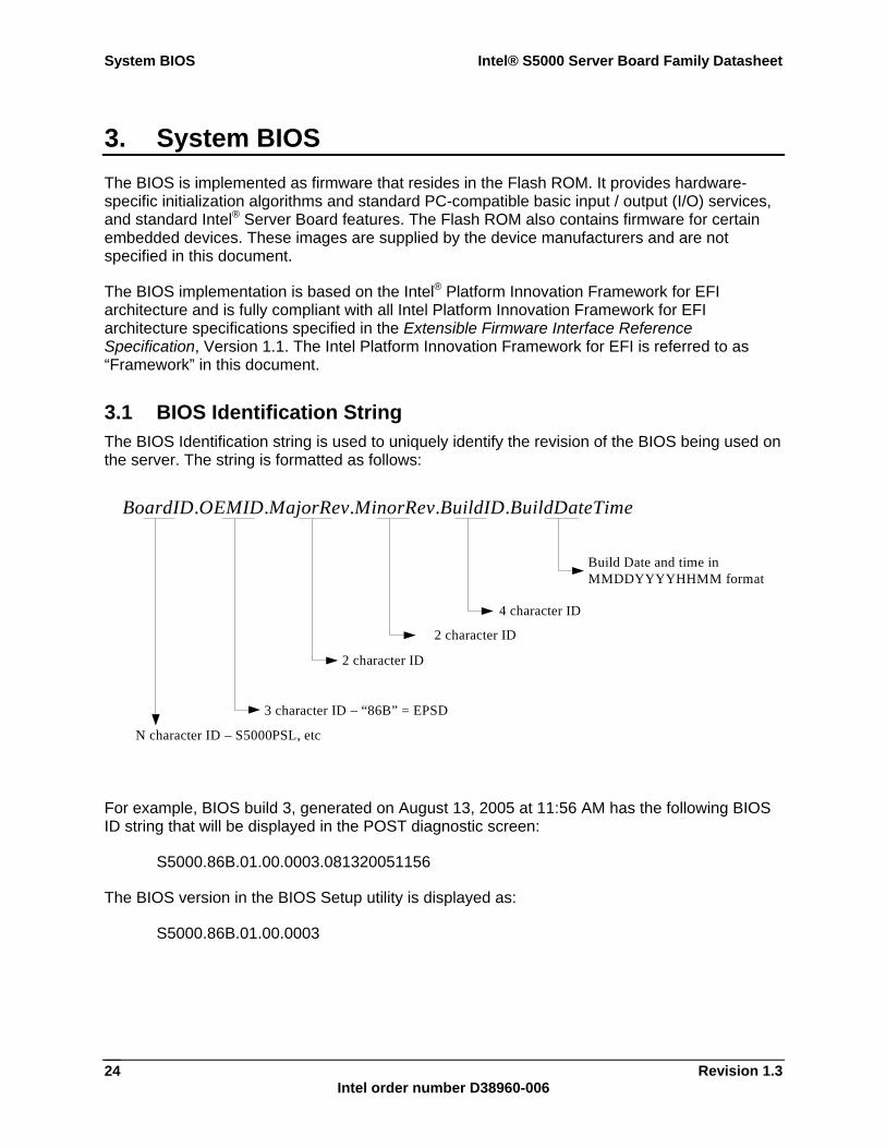
System BIOS Intel® S5000 Server Board Family Datasheet
Revision 1.3 Intel order number D38960-006
24
3. System BIOS The BIOS is implemented as firmware that resides in the Flash ROM. It provides hardware-specific initialization algorithms and standard PC-compatible basic input / output (I/O) services, and standard Intel® Server Board features. The Flash ROM also contains firmware for certain embedded devices. These images are supplied by the device manufacturers and are not specified in this document.
The BIOS implementation is based on the Intel® Platform Innovation Framework for EFI architecture and is fully compliant with all Intel Platform Innovation Framework for EFI architecture specifications specified in the Extensible Firmware Interface Reference Specification, Version 1.1. The Intel Platform Innovation Framework for EFI is referred to as “Framework” in this document.
3.1 BIOS Identification String The BIOS Identification string is used to uniquely identify the revision of the BIOS being used on the server. The string is formatted as follows:
BoardID.OEMID.MajorRev.MinorRev.BuildID.BuildDateTime
N character ID – S5000PSL, etc
3 character ID – “86B” = EPSD
2 character ID
2 character ID
4 character ID
Build Date and time inMMDDYYYYHHMM format
For example, BIOS build 3, generated on August 13, 2005 at 11:56 AM has the following BIOS ID string that will be displayed in the POST diagnostic screen:
S5000.86B.01.00.0003.081320051156
The BIOS version in the BIOS Setup utility is displayed as:
S5000.86B.01.00.0003
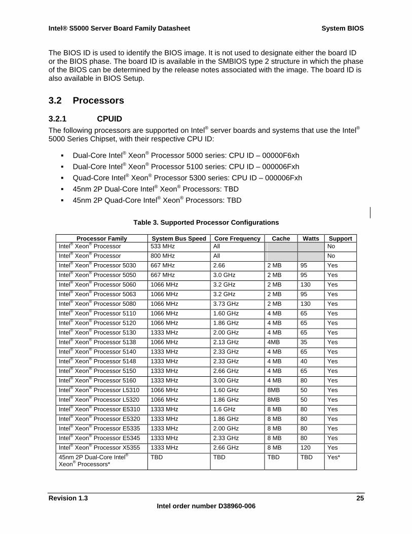
Intel® S5000 Server Board Family Datasheet System BIOS
Revision 1.3 Intel order number D38960-006
25
The BIOS ID is used to identify the BIOS image. It is not used to designate either the board ID or the BIOS phase. The board ID is available in the SMBIOS type 2 structure in which the phase of the BIOS can be determined by the release notes associated with the image. The board ID is also available in BIOS Setup.
3.2 Processors
3.2.1 CPUID The following processors are supported on Intel® server boards and systems that use the Intel® 5000 Series Chipset, with their respective CPU ID:
Dual-Core Intel® Xeon® Processor 5000 series: CPU ID – 00000F6xh Dual-Core Intel® Xeon® Processor 5100 series: CPU ID – 000006Fxh Quad-Core Intel® Xeon® Processor 5300 series: CPU ID – 000006Fxh 45nm 2P Dual-Core Intel® Xeon® Processors: TBD 45nm 2P Quad-Core Intel® Xeon® Processors: TBD
Table 3. Supported Processor Configurations
Processor Family System Bus Speed Core Frequency Cache Watts Support Intel® Xeon® Processor 533 MHz All No Intel® Xeon® Processor 800 MHz All No Intel® Xeon® Processor 5030 667 MHz 2.66 2 MB 95 Yes Intel® Xeon® Processor 5050 667 MHz 3.0 GHz 2 MB 95 Yes Intel® Xeon® Processor 5060 1066 MHz 3.2 GHz 2 MB 130 Yes Intel® Xeon® Processor 5063 1066 MHz 3.2 GHz 2 MB 95 Yes Intel® Xeon® Processor 5080 1066 MHz 3.73 GHz 2 MB 130 Yes Intel® Xeon® Processor 5110 1066 MHz 1.60 GHz 4 MB 65 Yes Intel® Xeon® Processor 5120 1066 MHz 1.86 GHz 4 MB 65 Yes Intel® Xeon® Processor 5130 1333 MHz 2.00 GHz 4 MB 65 Yes Intel® Xeon® Processor 5138 1066 MHz 2.13 GHz 4MB 35 Yes Intel® Xeon® Processor 5140 1333 MHz 2.33 GHz 4 MB 65 Yes Intel® Xeon® Processor 5148 1333 MHz 2.33 GHz 4 MB 40 Yes Intel® Xeon® Processor 5150 1333 MHz 2.66 GHz 4 MB 65 Yes Intel® Xeon® Processor 5160 1333 MHz 3.00 GHz 4 MB 80 Yes Intel® Xeon® Processor L5310 1066 MHz 1.60 GHz 8MB 50 Yes Intel® Xeon® Processor L5320 1066 MHz 1.86 GHz 8MB 50 Yes Intel® Xeon® Processor E5310 1333 MHz 1.6 GHz 8 MB 80 Yes Intel® Xeon® Processor E5320 1333 MHz 1.86 GHz 8 MB 80 Yes Intel® Xeon® Processor E5335 1333 MHz 2.00 GHz 8 MB 80 Yes Intel® Xeon® Processor E5345 1333 MHz 2.33 GHz 8 MB 80 Yes Intel® Xeon® Processor X5355 1333 MHz 2.66 GHz 8 MB 120 Yes 45nm 2P Dual-Core Intel® Xeon® Processors*
TBD TBD TBD TBD Yes*
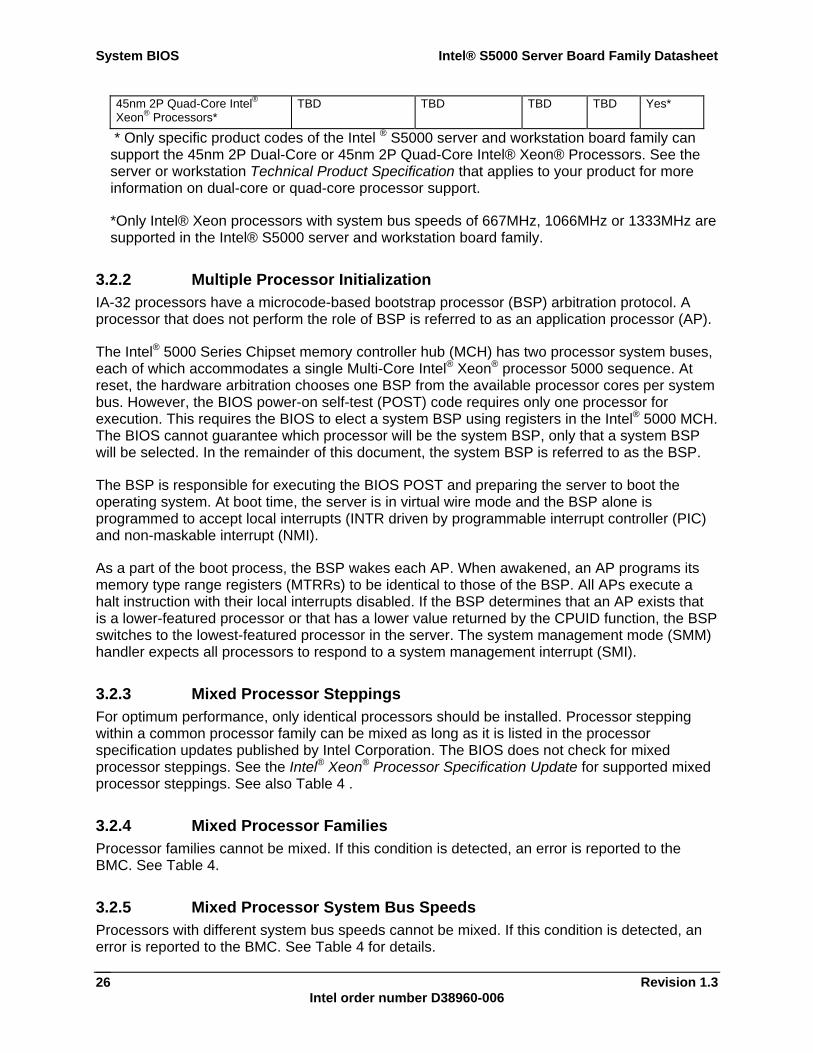
System BIOS Intel® S5000 Server Board Family Datasheet
Revision 1.3 Intel order number D38960-006
26
45nm 2P Quad-Core Intel® Xeon® Processors*
TBD TBD TBD TBD Yes*
* Only specific product codes of the Intel ® S5000 server and workstation board family can support the 45nm 2P Dual-Core or 45nm 2P Quad-Core Intel® Xeon® Processors. See the server or workstation Technical Product Specification that applies to your product for more information on dual-core or quad-core processor support.
*Only Intel® Xeon processors with system bus speeds of 667MHz, 1066MHz or 1333MHz are supported in the Intel® S5000 server and workstation board family.
3.2.2 Multiple Processor Initialization IA-32 processors have a microcode-based bootstrap processor (BSP) arbitration protocol. A processor that does not perform the role of BSP is referred to as an application processor (AP).
The Intel® 5000 Series Chipset memory controller hub (MCH) has two processor system buses, each of which accommodates a single Multi-Core Intel® Xeon® processor 5000 sequence. At reset, the hardware arbitration chooses one BSP from the available processor cores per system bus. However, the BIOS power-on self-test (POST) code requires only one processor for execution. This requires the BIOS to elect a system BSP using registers in the Intel® 5000 MCH. The BIOS cannot guarantee which processor will be the system BSP, only that a system BSP will be selected. In the remainder of this document, the system BSP is referred to as the BSP.
The BSP is responsible for executing the BIOS POST and preparing the server to boot the operating system. At boot time, the server is in virtual wire mode and the BSP alone is programmed to accept local interrupts (INTR driven by programmable interrupt controller (PIC) and non-maskable interrupt (NMI).
As a part of the boot process, the BSP wakes each AP. When awakened, an AP programs its memory type range registers (MTRRs) to be identical to those of the BSP. All APs execute a halt instruction with their local interrupts disabled. If the BSP determines that an AP exists that is a lower-featured processor or that has a lower value returned by the CPUID function, the BSP switches to the lowest-featured processor in the server. The system management mode (SMM) handler expects all processors to respond to a system management interrupt (SMI).
3.2.3 Mixed Processor Steppings For optimum performance, only identical processors should be installed. Processor stepping within a common processor family can be mixed as long as it is listed in the processor specification updates published by Intel Corporation. The BIOS does not check for mixed processor steppings. See the Intel® Xeon® Processor Specification Update for supported mixed processor steppings. See also Table 4 .
3.2.4 Mixed Processor Families Processor families cannot be mixed. If this condition is detected, an error is reported to the BMC. See Table 4.
3.2.5 Mixed Processor System Bus Speeds Processors with different system bus speeds cannot be mixed. If this condition is detected, an error is reported to the BMC. See Table 4 for details.

Intel® S5000 Server Board Family Datasheet System BIOS
Revision 1.3 Intel order number D38960-006
27
3.2.6 Mixed Processor Cache Sizes If the installed processors have mixed cache sizes, an error is reported to the BMC. The size of all cache levels must match between all installed processors. See Table 4.
3.2.7 Microcode Update If the system BIOS detects a processor for which a microcode update is not available, the BIOS reports an error to the BMC. See Table 4.
IA-32 processors can correct specific errata by loading an Intel-supplied data block, known as a microcode update. The BIOS stores the update in non-volatile memory and loads it into each processor during POST. The BIOS allows a number of microcode updates to be stored in the flash. This is limited by the amount of free space available.
3.2.8 Processor Cache The BIOS enables all levels of processor cache as early as possible during POST. There are no user options to modify the cache configuration, size, or policies. All detected cache sizes are reported in the SMBIOS Type 7 structures. The largest and highest-level cache detected is reported in BIOS Setup.
3.2.9 Mixed Processor Configuration The following table describes mixed processor conditions and actions for all Intel® server boards and systems that use the Intel® 5000 Series Chipset. Errors fall into one of two categories:
Halt: If the system can boot it will go directly to the error manager, regardless of the “Post Error Pause” setup option.
Pause: If “Post Error Pause” setup option is enabled, system will go directly to the error manager. Otherwise the system will continue to boot and no prompt is given for the error. The error is logged to the error manager.
Table 4. Mixed Processor Configurations
Error Severity System Action Processor family not Identical
Fatal The BIOS detects the error condition and responds as follows: Logs the error into the system event log (SEL)
Alerts the BMC of the configuration error with an IPMI command.
Does not disable the processor
Displays “0194: Processor family mismatch detected” message in the error manager
Halts the system
Processor cache not identical
Fatal The BIOS detects the error condition and responds as follows: Logs the error into the SEL
Alerts the BMC of the configuration error with an IPMI command.
Does not disable the processor
Displays “0192: Cache size mismatch detected” message in the error manager
Halts the system
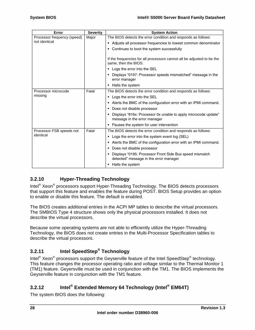
System BIOS Intel® S5000 Server Board Family Datasheet
Revision 1.3 Intel order number D38960-006
28
Error Severity System Action Processor frequency (speed) not identical
Major The BIOS detects the error condition and responds as follows: Adjusts all processor frequencies to lowest common denominator
Continues to boot the system successfully
If the frequencies for all processors cannot all be adjusted to be the same, then the BIOS: Logs the error into the SEL
Displays “0197: Processor speeds mismatched” message in the error manager
Halts the system
Processor microcode missing
Fatal The BIOS detects the error condition and responds as follows: Logs the error into the SEL
Alerts the BMC of the configuration error with an IPMI command.
Does not disable processor
Displays “816x: Processor 0x unable to apply microcode update” message in the error manager
Pauses the system for user intervention
Processor FSB speeds not identical
Fatal The BIOS detects the error condition and responds as follows: Logs the error into the system event log (SEL)
Alerts the BMC of the configuration error with an IPMI command.
Does not disable processor
Displays “0195: Processor Front Side Bus speed mismatch detected” message in the error manager
Halts the system
3.2.10 Hyper-Threading Technology Intel® Xeon® processors support Hyper-Threading Technology. The BIOS detects processors that support this feature and enables the feature during POST. BIOS Setup provides an option to enable or disable this feature. The default is enabled.
The BIOS creates additional entries in the ACPI MP tables to describe the virtual processors. The SMBIOS Type 4 structure shows only the physical processors installed. It does not describe the virtual processors.
Because some operating systems are not able to efficiently utilize the Hyper-Threading Technology, the BIOS does not create entries in the Multi-Processor Specification tables to describe the virtual processors.
3.2.11 Intel SpeedStep® Technology Intel® Xeon® processors support the Geyserville feature of the Intel SpeedStep® technology. This feature changes the processor operating ratio and voltage similar to the Thermal Monitor 1 (TM1) feature. Geyersville must be used in conjunction with the TM1. The BIOS implements the Geyserville feature in conjunction with the TM1 feature.
3.2.12 Intel® Extended Memory 64 Technology (Intel® EM64T) The system BIOS does the following:
Intel® S5000 Server Board Family Datasheet System BIOS
Revision 1.3 Intel order number D38960-006
29
Detects whether the processor is Intel® Extended Memory 64 Technology (Intel® EM64T) capable
Initializes the SMBASE for each processor Detects the appropriate SMRAM State Save Map used by the processor Enables Intel® EM64T during memory initialization if necessary
3.2.13 Execute Disable Bit Feature The Execute Disable Bit feature (XD bit) is an enhancement to the IA-32 Intel® architecture. An IA-32 processor that supports the Execute Disable Bit feature can prevent data pages from being used by malicious software to execute code. An IA-32 processor with the XD bit feature can provide memory protection in either of the following modes:
Legacy protected mode if the Physical Address Extension (PAE) is enabled. IA-32e mode when 64-bit extension technology is enabled (Entering IA-32e mode
requires enabling PAE).
The XD bit does not introduce any new instructions, it requires operating systems to operate in a PAE-enabled environment and establish a page-granular protection policy for memory. The XD bit can be enabled and disabled in BIOS Setup. The default behavior is enabled.
3.2.14 Enhanced Halt State (C1E) All processors support the Halt State (C1) through the native processor instructions HLT and MWAIT. Some processors implement an optimization of the C1 state called the Enhanced Halt State (C1E) to further reduce the total power consumption while in C1. When C1E is enabled, and all logical processors in the physical processors have entered the C1 state, the processor will reduce the core clock frequency to system bus ratio and VID. The transition of the physical processor from C1 to C1E is accomplished similar to an Enhanced Intel SpeedStep® Technology transition. If the BIOS determines all the system processors support C1E, then it is enabled.
3.2.15 Multi-Core Processor Support The BIOS does the following:
Initializes all processor cores Installs all NMI handlers for all dual core processors Leaves initialized AP in CLI/HLT loop Initializes stack for all APs
BIOS Setup provides an option to selectively enable or disable multi-core processor support. The default behavior is enabled.
The BIOS creates additional entries in the ACPI MP tables to describe the dual core processors. The SMBIOS Type 4 structure shows only the physical processors installed. It does not describe the virtual processors.
System BIOS Intel® S5000 Server Board Family Datasheet
Revision 1.3 Intel order number D38960-006
30
The BIOS will create entries in the multi-processor specification tables to describe dual core processors.
3.2.16 Intel® Virtualization Technology Intel® Virtualization Technology is designed to support multiple software environments sharing the same hardware resources. Each software environment may consist of operating system and applications. The Intel® Virtualization Technology can be enabled or disabled in BIOS Setup. The default behavior is disabled.
Note: If the Setup options are changed to enable or disable the Intel® Virtualization Technology setting in the processor, the user must perform an AC power cycle before the changes will take effect.
3.2.17 Fake MSI Support In PCI compatible INTx mode, the Intel® 5000 Series Chipsets supports a maximum of four unique interrupts. If more than four unique interrupts are used by devices behind the Intel® 5000 Series Chipset root ports, it could result in a potential interrupt scaling problem due to sharing of interrupts. On an Intel® 5000 based platform that supports eight processor cores, the configuration allows for interrupt distribution to all eight cores. Since the available number of unique interrupts (4) is less than the number of available cores (8), the platform cannot take advantage of all the available cores for interrupt distribution. However, the Intel® 5000 Series Chipsets provides an interrupt scaling feature called Fake MSI to mitigate this problem.
3.2.17.1 Overview of Fake MSI Support All PCIe devices are required to support MSI (Message Signaled Interrupt). In this scheme, the device causes an interrupt by writing the value of the MSI data register to the address contained in the MSI address register. The resulting memory write transaction is translated through chipset logic into an interrupt transaction for the appropriate target processor core(s). However, the MSI scheme requires support in the OS which is not widely available in currently shipping operating systems. The Fake MSI scheme allows PCIe devices running on such legacy operating systems to use the MSI mechanism to generate INTx compatible interrupts. This is accomplished by targeting the MSI memory write to an IOxAPIC in the system.
Under the Fake MSI scheme, PCI-Express devices are programmed to enable MSI functionality, and given a write path directly to the pin assertion register (PAR) of an IOxAPIC already present in the platform. The targeted IOxAPIC will now generate an APIC interrupt message in response to a memory write to the PAR, thus providing equivalent functionality to a virtual (edge-triggered) wire between the PCI-Express endpoint and the IOxAPIC. The Intel® 5000 Series Chipsets ensure that PCI ordering rules are maintained for the Fake MSI memory write.
All PCI-Express devices are required to support MSI. When Fake MSI is enabled, the PCI-Express devices generate a memory transaction with an address equal to I/OxAPIC_MEM_BAR + 0x20 (PAR) and a 32-bit data equal to the interrupt vector number corresponding to the device. This information is stored in the device's MSI address and data registers, and would be initialized by the system firmware (BIOS) prior to booting a non-MSI aware operating system.
Intel® S5000 Server Board Family Datasheet System BIOS
Revision 1.3 Intel order number D38960-006
31
3.2.17.2 Fake MSI Scheme Limitations The following limitations of the Fake MSI Scheme should be understood before using it in a platform:
1. The Fake MSI scheme can only be used by IO devices that support MSI capability (all PCIe devices are required to support either MSI or MSI-X).
2. The Fake MSI scheme cannot be used with a device that supports MSI-X1 (i.e., the device supports MSI-X only and does not support MSI).
3. The Fake MSI scheme can be used with MSI capable devices only. It cannot be used with a device that only supports MSI-X.
4. The I/OxAPIC interrupt used for Fake MSI cannot be shared. This is because MSI is an edge triggered mechanism and sharing will result in loss of interrupts.
5. Even if the IO device is multiple message capable, firmware must program the device to allocate one vector only (the Fake MSI scheme cannot support MSI multiple messages). This is required in order to ensure that the device-function does not modify any bits of the message data field.
6. Each IO device that intends to use the Fake MSI scheme should be programmed to a unique MSI data value corresponding to a unique I/OxAPIC input. The MSI address remains the same as we are targeting the PAR of the ESB2 I/OxAPIC.
7. If the IO device generates interrupts for multiple internal events, the device driver ISR must check for all internal events on each interrupt2. Otherwise, overrun situations are possible.
8. In case of multi-function devices, the Fake MSI scheme can be used to support up to 4 functions only. This is because interrupt routing of devices using the Fake MSI scheme are exposed to the operating system using MPS1.4 or _PRT table; these firmware tables are limited to 4 unique interrupts per device as required by the PCI Specification.
3.2.18 Acoustical Fan Speed Control The processors implement a methodology for managing processor temperatures that supports acoustic noise reduction through fan speed control. There are two components to the temperature calculation used to regulate the fans: TCONTROL offset and TCONTROL base. The BIOS retrieves the TCONTROL offset from a processor MSR and sends it to the BMC. The BMC is responsible for getting the TCONTROL base from the sensor data records and adding it to the value received from the BIOS.
1 MSI-X requires BAR registers to be initialized to locate the MSI-X table in MMIO space. Since legacy operating systems could potentially reconfigure the device and its BARs, in the case of “Fake MSI”, there is a risk of losing the MSI-X programming done by the BIOS. 2 The concern here is that a device driver written with level triggered semantics in mind may dismiss the interrupt with processing all the internal events associated with the interrupt because it is assured that the interrupt will be reasserted as long as internal events are pending.
System BIOS Intel® S5000 Server Board Family Datasheet
Revision 1.3 Intel order number D38960-006
32
3.3 Memory The Intel® 5000 MCH supports fully-buffered DIMM (FBDIMM) technology. The integrated Memory Controller Hub in the Intel® 5000 MCH divides the FBDIMMs on the board into two autonomous sets called branches. Each branch has two channels. In dual-channel mode, FBDIMMs on adjacent channels work in lock-step to provide the same cache line data, and a combined ECC. In the single-channel mode, only Channel 0 is active.
The BIOS is able to configure the memory controller dynamically in accordance with the available FBDIMM population and the selected RAS (reliability, availability, serviceability) mode of operation.
3.3.1 Memory Sizing and Configuration The BIOS supports various memory module sizes and configurations. These combinations of sizes and configurations are valid only for FBDIMMs approved by Intel. The BIOS reads the Serial Presence Detect (SPD) SEEPROMs on each installed memory module to determine the size and timing characteristics of the installed memory modules (FBDIMMs). The memory-sizing algorithm then determines the cumulative size of each row of FBDIMMs. The BIOS programs the memory controller in the chipset accordingly, such that the range of memory accessible from the processor is mapped into the correct FBDIMM or set of FBDIMMs.
3.3.2 POST Error Codes The range {0xE0, 0xEF} of POST codes is used for memory errors in early POST. In late POST, this range is used for reporting other system errors.
If no memory is available, the system will emit POST Diagnostic LED code 0xE1 and halt the system.
If the system is unable to communicate with the FBDIMMs, the BIOS will eventually time out and report POST Diagnostic LED code 0xE4. This is usually indicative of hardware failure.
If a FBDIMM or a set of FBDIMMs on the same FBD memory channel (row) fails Memory Intel® Interconnect built in self test (Intel® IBIST), or Memory Link Training, the BIOS will emit POST Diagnostic LED code 0xE6. If all of the memory fails IBIST the system will act as if no memory is available.
Any of the above errors cause a memory error beep code. Memory beep code errors are described in Section 5.3.2, POST Code Checkpoints.
3.3.3 Publishing System Memory The BIOS displays the total memory of the system during POST if the display logo is
disabled in the BIOS Setup utility. Total memory is the total size of memory discovered by the BIOS during POST, and is the sum of the individual sizes of installed FBDIMMs. The total memory is also displayed on the main page of the BIOS Setup utility.
The BIOS displays the effective memory of the system in the BIOS Setup utility. Effective memory is the total size of all FBDIMMs that are active (not disabled) and not used as redundant units.
Intel® S5000 Server Board Family Datasheet System BIOS
Revision 1.3 Intel order number D38960-006
33
If the Display Logo is disabled, the BIOS displays the total system memory on the diagnostic screen at the end of POST. This total is the same as the amount described by the first bullet, above.
The BIOS provides the total amount of memory in the system by supporting the EFI Boot Service function GetMemoryMap().
The BIOS provides the total amount of memory in the system by supporting the INT 15h, E820h function. See the Advanced Configuration and Power Interface Specification, Revision 2.0 for details.
Note: Memory between 4 GB and 4 GB minus 1.5 GB is not accessible for use by the operating system and may be lost to the user. This area is reserved for BIOS, APIC configuration space, and virtual video memory space. See section 3.3.3.1. Memory will also be reserved for PCI / PCI Express* / PCI Express resources. This means that if 4 GB of memory is installed, 2.5 GB or less of this memory is usable. The chipset allows remapping unused memory above the 4 GB address. To take advantage of this, turn on Physical Address Extensions (PAE) in your operating system.
3.3.3.1 Memory Reservation for Memory-mapped Functions A region of size 0.25 GB of memory below 4 GB is always reserved for mapping chipset, processor and BIOS (flash) spaces as memory-mapped I/O regions. This region will appear as a loss of memory to the operating system. In addition to this loss, the BIOS creates another reserved region for memory-mapped PCI Express* functions, including a standard 0.25 GB of standard PC Express configuration space. This memory is reclaimed by the operating system if PAE is turned on in the operating system.
3.3.3.2 High-Memory Reclaim When 4 GB or more of physical memory is installed, the reserved memory is lost. However, the Intel® 5000 Series Chipset provides a feature called high-memory reclaim that allows the BIOS and the operating system to remap the lost physical memory into system memory above 4 GB. The system memory is the memory that can be seen by the processor.
The BIOS will always enable high-memory reclaim if it discovers installed physical memory equal to or greater than 4 GB. For the operating system, the reclaimed memory is recoverable only when it supports and enables the PAE feature in the processor. Most operating systems support this feature. See the relevant operating system manuals for operating system support in your environment.
3.3.3.3 Memory Interleaving In general, to optimize memory accesses, the BIOS will enable Branch Interleaving, which allows the chipset to interleave data for successive cache-lines between the autonomous branches. Branch Interleaving is not possible on some platforms, since these do not have Branch 1 enabled.
Additionally, the Intel® 5000 sequence MCH also provides interleaving across logical memory devices called ranks. A pair of single-ranked lock-stepped FBDIMMs constitutes a memory rank. Interleaving effected between ranks allows the chipset to interleave cache-line data between
System BIOS Intel® S5000 Server Board Family Datasheet
Revision 1.3 Intel order number D38960-006
34
participant ranks, and the process is called Rank Interleaving. The BIOS by default enables 4:1 Rank Interleaving, in which 4 ranks participate in a single cache-line access.
3.3.4 Mixed Speed Memory Modules The BIOS supports memory modules of mixed speed through a combination of user-selected input frequency and the capability of each memory module (FBDIMM). This section describes the expected outcome on installation of FBDIMMs of different frequencies in the system, for a given user-selected frequency.
3.3.4.1 FBDIMM Characteristics To program a FBDIMM to function correctly for a given frequency, the BIOS queries each FBDIMM’s Serial-presence Data (SPD) store. The SPD contains the frequency characteristics of the FBDIMM, which are measured in terms of the following parameters:
CAS latency (CL) Common clock frequency Additive latency (AL) Buffer read delay (BRD)
The CAS latency and the additive latency are configurable parameters that are detected by the BIOS by reading the SPD data of the FBDIMMs. The BRD is the average inherent delay that is caused by the finite time that the AMB consumes in buffering the data read from the DRAMs before forwarding it on the northbound or southbound path.
3.3.4.2 Host Frequency and Gear Ratio The host frequency is the speed of the memory interface of the Intel® 5000 Series Chipset. This frequency determines the speed at which the chipset completes a memory transaction. The gear ratio determines the relative speed between the processor interface and the memory interface.
The BIOS supports two frequencies: 533 MHz and 667 MHz. The BIOS also provides an auto-select feature that provides automatic selection and configuration of the host frequency and gear ratio.
During memory discovery, the BIOS keeps track of the minimum latency requirements of each installed FBDIMM by recording relevant latency requirements from each FBDIMM’s SPD data. The BIOS then arrives at a common frequency that matches the requirements of all components and then configures the memory system, as well as the FBDIMMs, for that common frequency.
3.3.5 Memory Test
3.3.5.1 Integrated Memory BIST Engine The Intel® 5000 MCH incorporates an integrated Memory Built-in Self Test (BIST) engine that is enabled to provide extensive coverage of memory errors at both the memory cell level, as well as the data paths emanating from the FBDIMMs.
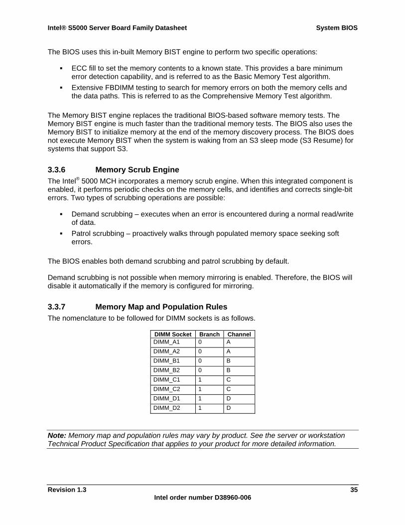
Intel® S5000 Server Board Family Datasheet System BIOS
Revision 1.3 Intel order number D38960-006
35
The BIOS uses this in-built Memory BIST engine to perform two specific operations:
ECC fill to set the memory contents to a known state. This provides a bare minimum error detection capability, and is referred to as the Basic Memory Test algorithm.
Extensive FBDIMM testing to search for memory errors on both the memory cells and the data paths. This is referred to as the Comprehensive Memory Test algorithm.
The Memory BIST engine replaces the traditional BIOS-based software memory tests. The Memory BIST engine is much faster than the traditional memory tests. The BIOS also uses the Memory BIST to initialize memory at the end of the memory discovery process. The BIOS does not execute Memory BIST when the system is waking from an S3 sleep mode (S3 Resume) for systems that support S3.
3.3.6 Memory Scrub Engine The Intel® 5000 MCH incorporates a memory scrub engine. When this integrated component is enabled, it performs periodic checks on the memory cells, and identifies and corrects single-bit errors. Two types of scrubbing operations are possible:
Demand scrubbing – executes when an error is encountered during a normal read/write of data.
Patrol scrubbing – proactively walks through populated memory space seeking soft errors.
The BIOS enables both demand scrubbing and patrol scrubbing by default.
Demand scrubbing is not possible when memory mirroring is enabled. Therefore, the BIOS will disable it automatically if the memory is configured for mirroring.
3.3.7 Memory Map and Population Rules The nomenclature to be followed for DIMM sockets is as follows.
DIMM Socket Branch Channel DIMM_A1 0 A DIMM_A2 0 A DIMM_B1 0 B DIMM_B2 0 B DIMM_C1 1 C DIMM_C2 1 C DIMM_D1 1 D DIMM_D2 1 D
Note: Memory map and population rules may vary by product. See the server or workstation Technical Product Specification that applies to your product for more detailed information.
System BIOS Intel® S5000 Server Board Family Datasheet
Revision 1.3 Intel order number D38960-006
36
3.3.7.1 Memory Sub-system Nomenclature FBDIMMs are organized into physical slots on memory channels that belong to memory
branches. Each branch can support a maximum of four DIMM sockets per channel. The memory channels are identified as Channel A, B, C, and D. Channels A and B belong to Branch 0. Channels C and D belong to Branch 1. The DIMM identifiers on the silkscreen on the board provide information about which
channel, and therefore which branch, they belong to. For example, DIMM_A1 is the first slot on Channel A on Branch 0. DIMM_C1 is the first DIMM socket on Channel C on Branch 1.
3.3.7.2 Memory Upgrade Rules Upgrading the system memory requires careful positioning of the FBDIMMs, based on the following factors:
The current mode of operation The existing FBDIMM population The FBDIMM characteristics The optimization techniques used by the Intel® 5000 MCH to maximize FBD bandwidth.
In dual-channel mode, the adjacent channels of a branch work in lock-step to provide increase in FBD bandwidth. Channel A and Channel B are lock-stepped when Branch 0 is configured to support dual-channel mode, Channel C and Channel D are lock-stepped when Branch 1 is configured for lock-step.
In single-channel mode, only Channel A, Branch 0 can be active. In this mode, Branch 1 is always disabled. Accordingly, only FBDIMMs on Channel A are enabled. All other FBDIMMs are disabled.
The following are the general rules to be observed when selecting and configuring memory to obtain the best performance from the system.
Rule 1: the Dual-channel or lock-stepped mode of operation is always the preferred mode of operation, irrespective of the branch on which it is possible.
Rule 2: Branch 0 is usually given precedence over Branch 1 in determining the mode of operation. The only exception to this rule is when Branch 1 satisfies Rule #1 above, but Branch 0 cannot.
Rule 3: Both branches are autonomous and capable of being independently initialized. However, the minimal upgrade for Branch 1 is DIMM_C1/DIMM_D1 such that Rule #1 is satisfied.
Rule 4: If an installed FBDIMM has faulty or incompatible SPD data, it will be ignored during the lock-step selection process, and thus essentially disabled by the BIOS. If the FBDIMM has no or missing SPD information, the slot on which it is placed will be treated as empty by the BIOS.
Intel® S5000 Server Board Family Datasheet System BIOS
Revision 1.3 Intel order number D38960-006
37
Rule 5: The FBDIMM population of Slot 1 on Branch 0 determines the mode that is selected. If DIMM_A1 and DIMM_B1 cannot lock-step, then the system reverts to single-channel mode, with DIMM_B1 disabled.
Rule 6: As long as Branch 1 cannot satisfy Rules 1 or 2, the Single-channel mode is always given preference over dual-channel mode if the configuration on Slot 1, Branch 0 is not in balance (if DIMM_A1 and DIMM_B1 are not identical.)
Rule 7: DIMM_A1 must always be populated, except the special case mentioned in Rule 2. In addition, the BIOS will always select the mode of operation that best matches the requirements of DIMM_A1, such that it is always enabled and used for runtime memory. For example, in a FBDIMM population that has Branch 0 with only DIMM_A1 populated, the BIOS will forcibly initialize and configure single-channel mode with only DIMM_A1 enabled, regardless of the number of FBDIMMs populated on Branch 1. Such a method of upgrading system memory is, therefore, incorrect, and results in a reduced-capacity operation. It must, therefore, be avoided.
Rule 8: DIMM_A1 is the minimum possible FBDIMM configuration. In this configuration, the memory operates in single-channel mode, and no RAS features are possible.
Rule 9: The minimum memory population recommended by Intel for enabling Branch 1 is four FBDIMMs: DIMM_A1, DIMM_B1, DIMM_C1 and DIMM_D1.
Rule 10: For a branch to operate in lock-step (dual-channel mode), the FBDIMMs in socket positions on adjacent channels of the branch must be identical in terms of timing, technology, and size. Therefore, DIMM_A1 and DIMM_B1 must be identical for Branch 1 to work in dual-channel mode. If the FBDIMMs on adjacent channels of a branch are not identical, the FBDIMM on the higher channel is disabled.
Rule 11: FBDIMMs on adjacent slots on the same channel do not need to be identical. Rule 12: The minimum memory upgrade for memory mirroring is four FBDIMMs:
DIMM_A1, DIMM_B1, DIMM_C1 and DIMM_D1. Memory mirroring inherently relies on the dual-channel mode of operation.
Rule 13: The minimum population for memory pair sparing is four FBDIMMs in dual channel mode: DIMM_A1, DIMM_A2, DIMM_B1, and DIMM_B2.
Rule 14: Once the FBDIMMs installed on the adjacent channels of a branch have lock-stepped, the resultant FBDIMM pair is treated as a single “logical” device thereafter. Therefore, if one of the DIMMs in this lock-stepped pair fails Memory BIST or Channel IBIST during POST, the BIOS will disable both FBDIMMs of the logical combination. Similarly, if one of these DIMMs has a runtime transient uncorrectable error, both DIMMs will be simultaneously disabled.
During the memory discovery phase of POST, the BIOS will disable any FBDIMM that does not conform to the rules.
For platforms that support only a single FBD branch, such as the Intel® Server Board S5000VSA, the same rules are applicable, except for rules that pertain to Branch 1.
3.3.7.3 Examples of FBDIMM Population and Upgrade Rules See the server or workstation Technical Product Specification that applies to your product for detailed information on FBDIMM population and upgrade rules.
System BIOS Intel® S5000 Server Board Family Datasheet
Revision 1.3 Intel order number D38960-006
38
3.3.8 Memory Modes of Operation Based on the available FBDIMM population, the BIOS will configure the system memory into the best possible configuration. Possible configurations in RAS mode are:
Single-channel mode Maximum interleave mode (dual-channel mode) Memory mirroring mode DIMM sparing mode (dual or single FBDIMM)
Single-channel and dual-channel modes are special cases when RAS is disabled. In single-channel mode, only one channel is active on each branch, with the adjacent channel disabled. In dual-channel mode, the FBDIMMs on adjacent channels on each branch are configured for maximum interleave in order to provide the optimal lock-step operation.
3.3.9 Memory RAS
3.3.9.1 RAS Features Server boards based on the Intel® 5000 Series Chipsets support the following memory RAS features:
Memory mirroring Memory sparing Automatic thermal throttling Fully-buffered DIMM (FBD) Channel Intel® Interconnect BIST (Intel® IBIST)
These standard RAS modes are used in conjunction with the standard memory test and memory scrub engines to provide full RAS support. Some of the RAS features are implemented differently on some boards.
3.3.9.2 Memory Sparing All versions of the Intel® 5000 Series Chipset provide memory sparing capabilities. Sparing is a RAS feature that involves configuring of a FBDIMM on the server board to be placed in reserve so it can be use to replace an FBDIMM that fails.
Spared memory configurations do not provide redundant copies of memory and the system can not continue to operate when an uncorrectable error occurs. The purpose of memory sparing is to detect a failing FBDIMM before it causes a system crash. Once the affected FBDIMM is isolated and removed from the set of active FBDIMMs, the system integrity is maintained by copying the data from the failed FBDIMM to the reserved FBDIMM.
See Section 3.7.2.1.2 for BIOS Setup utility options to enable this feature. The BIOS Setup utility will show if memory sparing is possible with the current memory configuration.
Note: The DIMM sparing feature requires that the spare FBDIMM be at least the size of the largest primary FBDIMM in use. When sparing is enabled, the BIOS selects the spare automatically during POST. No manual configuration of this feature is required beyond turning
Intel® S5000 Server Board Family Datasheet System BIOS
Revision 1.3 Intel order number D38960-006
39
on the feature in BIOS Setup. With sparing enabled, the total effective memory size will be reduced by the size of the spare FBDIMM(s).
3.3.9.2.1 Dual-ranked DIMM Sparing When a dual-ranked FBDIMM is used as a spare, the BIOS has the ability to independently select a physical rank on that FBDIMM as the spare unit and utilize the other physical rank as a normal unit. This selective sparing ensures maximization of available memory while still providing RAS. However, populating differently-ranked FBDIMMs for sparing is not a good practice and may yield unpredictable results.
3.3.9.3 Minimum FBDIMM Population for Sparing For FBDIMM sparing, the minimum population is at least two FBDIMMs on the same channel on any branch. Selecting sparing from BIOS Setup will cause the BIOS to attempt enabling the feature on both branches to begin with, but actual configuration for a given branch will depend upon the population of FBDIMMs on that branch.
For example: Correct configurations for Branch 0 are DIMM A1, DIMM A2. An incorrect configuration for Branch 0 is DIMM A1. Because there is only one FBDIMM, none is available to act as a spare.
The spare FBDIMMs do not contribute to available physical memory under normal system operation. The Effective Memory field on the BIOS Setup utility screen will indicate this absence of memory for the sparing operation.
3.3.9.4 Memory Mirroring Unlike memory sparing, the mirrored configuration is a redundant image of the memory, and can continue to operate with some uncorrectable errors occur.
Memory mirroring is a RAS feature in which two identical images of memory data are maintained, providing maximum redundancy. On the Intel® 5000 MCH-based Intel server boards, mirroring is achieved across Branch 0 and Branch 1 such that one of these branches is the primary image and the other the secondary image. The memory controller always directs read transactions to the primary branch. Write transactions are directed to both branches under normal circumstances.
Because the available system memory is divided into a primary image and a copy of the image, the effective system memory is reduced by one-half. For example, if the system is operating in memory mirroring mode and the total size of the FBDIMMs is 1 GB, then the effective size of the memory is 512 MB because half of the FBDIMMs are the secondary images.
For memory mirroring to work, participant FBDIMMs on the same DIMM sockets on the adjacent branches must be identical in terms of technology, number of ranks, timing, and size.
The BIOS provides a setup option to enable memory mirroring. When memory mirroring is enabled, the BIOS attempts to configure the memory system accordingly. If the FBDIMM population is not suitable for mirroring, the BIOS disables mirroring and reverts to the default non-RAS mode with maximum interleave, or to the single channel mode. The BIOS setup then defaults to the eventual setting on the next boot.
System BIOS Intel® S5000 Server Board Family Datasheet
Revision 1.3 Intel order number D38960-006
40
See the server or workstation Technical Product Specification that applies to your product for more information.
3.3.9.4.1 Minimum FBDIMM Population for Mirroring Memory mirroring requires the following minimum requirements:
Branch configuration: Mirroring requires both branches to be active. Interleave configuration: Mirroring requires that interleaving at the channel level be
enabled on both branches such that the FBDIMMs on the adjacent channels work in lock-step.
As a direct consequence of these requirements, the minimum FBDIMM population is DIMM_A1, DIMM_B1, DIMM_C1, and DIMM_D1. For more information, see section 3.3.7.
In this mode the pair of DIMM A1 and DIMM B1, and the pair of DIMM_C1 and DIMM_D1 operate in lock-step on Branch 0 and Branch 1 respectively, meeting the requirements listed above. Therefore, the minimum number of FBDIMMs for mirroring is four, arranged as mentioned above. The BIOS will disable all non-identical FBDIMMs, or pairs of FBDIMMs, across the branches to achieve symmetry and balance between the branches.
3.3.9.5 Automatic Thermal Throttling The Intel® 5000 sequence MCH performs automatic electrical throttling on the FBDIMMs when there is heavy memory traffic, as in the case of a memory intensive application, which indirectly results in a rise in temperature of the advanced memory buffers (AMBs) on the FBDIMMs. The BIOS always enables electrical throttling.
The BIOS will send a command to the BMC telling it which fan profile is set in BIOS Setup (acoustic or performance) and then it will send an additional command to get the settings for that profile. The BIOS uses the parameters retrieved from the thermal sensor data records (SDR) and the altitude setting from BIOS Setup to configure the memory and the chipset for memory throttling and fan speed control. If the BIOS fails to get the thermal SDRs, then it will use the memory reference code (MRC) default settings for the thermal values.
3.3.10 Memory Error Handling This section describes the BIOS and chipset policies used for handling and reporting errors occurring in the memory sub-system.
3.3.10.1 Memory Error Classification The BIOS classifies memory errors into the following categories:
Correctable ECC errors: errors that occur in memory cells and result in corruption of memory, but are internally corrected by the ECC engine in the chipset.
Uncorrectable ECC errors: errors that occur in memory cells and result in data corruption. The chipset’s ECC engine detects these errors, but cannot correct them. These errors create a loss of data fidelity and are severe errors.
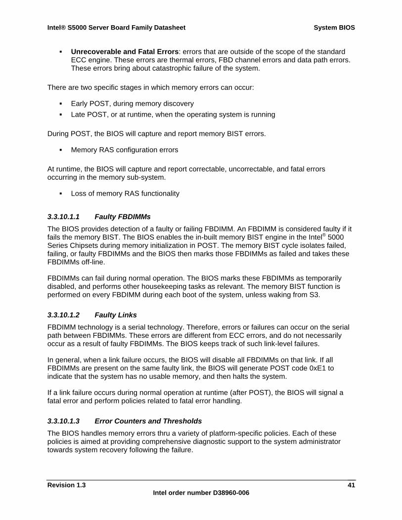
Intel® S5000 Server Board Family Datasheet System BIOS
Revision 1.3 Intel order number D38960-006
41
Unrecoverable and Fatal Errors: errors that are outside of the scope of the standard ECC engine. These errors are thermal errors, FBD channel errors and data path errors. These errors bring about catastrophic failure of the system.
There are two specific stages in which memory errors can occur:
Early POST, during memory discovery Late POST, or at runtime, when the operating system is running
During POST, the BIOS will capture and report memory BIST errors.
Memory RAS configuration errors
At runtime, the BIOS will capture and report correctable, uncorrectable, and fatal errors occurring in the memory sub-system.
Loss of memory RAS functionality
3.3.10.1.1 Faulty FBDIMMs The BIOS provides detection of a faulty or failing FBDIMM. An FBDIMM is considered faulty if it fails the memory BIST. The BIOS enables the in-built memory BIST engine in the Intel® 5000 Series Chipsets during memory initialization in POST. The memory BIST cycle isolates failed, failing, or faulty FBDIMMs and the BIOS then marks those FBDIMMs as failed and takes these FBDIMMs off-line.
FBDIMMs can fail during normal operation. The BIOS marks these FBDIMMs as temporarily disabled, and performs other housekeeping tasks as relevant. The memory BIST function is performed on every FBDIMM during each boot of the system, unless waking from S3.
3.3.10.1.2 Faulty Links FBDIMM technology is a serial technology. Therefore, errors or failures can occur on the serial path between FBDIMMs. These errors are different from ECC errors, and do not necessarily occur as a result of faulty FBDIMMs. The BIOS keeps track of such link-level failures.
In general, when a link failure occurs, the BIOS will disable all FBDIMMs on that link. If all FBDIMMs are present on the same faulty link, the BIOS will generate POST code 0xE1 to indicate that the system has no usable memory, and then halts the system.
If a link failure occurs during normal operation at runtime (after POST), the BIOS will signal a fatal error and perform policies related to fatal error handling.
3.3.10.1.3 Error Counters and Thresholds The BIOS handles memory errors thru a variety of platform-specific policies. Each of these policies is aimed at providing comprehensive diagnostic support to the system administrator towards system recovery following the failure.
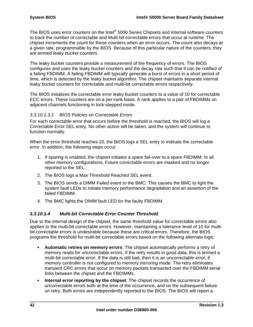
System BIOS Intel® S5000 Server Board Family Datasheet
Revision 1.3 Intel order number D38960-006
42
The BIOS uses error counters on the Intel® 5000 Series Chipsets and internal software counters to track the number of correctable and Multi-bit correctable errors that occur at runtime. The chipset increments the count for these counters when an error occurs. The count also decays at a given rate, programmable by the BIOS. Because of this particular nature of the counters, they are termed leaky bucket counters.
The leaky bucket counters provide a measurement of the frequency of errors. The BIOS configures and uses the leaky bucket counters and the decay rate such that it can be notified of a failing FBDIMM. A failing FBDIMM will typically generate a burst of errors in a short period of time, which is detected by the leaky bucket algorithm. The chipset maintains separate internal leaky bucket counters for correctable and multi-bit correctable errors respectively.
The BIOS initializes the correctable error leaky bucket counters to a value of 10 for correctable ECC errors. These counters are on a per-rank basis. A rank applies to a pair of FBDIMMs on adjacent channels functioning in lock-stepped mode.
3.3.10.1.3.1 BIOS Policies on Correctable Errors For each correctable error that occurs before the threshold is reached, the BIOS will log a Correctable Error SEL entry. No other action will be taken, and the system will continue to function normally.
When the error threshold reaches 10, the BIOS logs a SEL entry to indicate the correctable error. In addition, the following steps occur:
1. If sparing is enabled, the chipset initiates a spare fail-over to a spare FBDIMM. In all other memory configurations, Future correctable errors are masked and no longer reported to the SEL.
2. The BIOS logs a Max Threshold Reached SEL event.
3. The BIOS sends a DIMM Failed event to the BMC. This causes the BMC to light the system fault LEDs to initiate memory performance degradation and an assertion of the failed FBDIMM.
4. The BMC lights the DIMM fault LED for the faulty FBDIMM.
3.3.10.1.4 Multi-bit Correctable Error Counter Threshold Due to the internal design of the chipset, the same threshold value for correctable errors also applies to the multi-bit correctable errors. However, maintaining a tolerance level of 10 for multi-bit correctable errors is undesirable because these are critical errors. Therefore, the BIOS programs the threshold for multi-bit correctable errors based on the following alternate logic:
Automatic retries on memory errors: The chipset automatically performs a retry of memory reads for uncorrectable errors. If the retry results in good data, this is termed a multi-bit correctable error. If the data is still bad, then it is an uncorrectable error, if memory controller is not configured to memory mirroring mode. The retry eliminates transient CRC errors that occur on memory packets transacted over the FBDIMM serial links between the chipset and the FBDIMMs.
Internal error reporting by the chipset: The chipset records the occurrence of uncorrectable errors both at the time of the occurrence, and on the subsequent failure on retry. Both errors are independently reported to the BIOS. The BIOS will report a
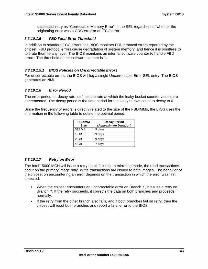
Intel® S5000 Server Board Family Datasheet System BIOS
Revision 1.3 Intel order number D38960-006
43
successful retry as “Correctable Memory Error” in the SEL regardless of whether the originating error was a CRC error or an ECC error.
3.3.10.1.5 FBD Fatal Error Threshold In addition to standard ECC errors, the BIOS monitors FBD protocol errors reported by the chipset. FBD protocol errors cause degradation of system memory, and hence it is pointless to tolerate them to any level. The BIOS maintains an internal software counter to handle FBD errors. The threshold of this software counter is 1.
3.3.10.1.5.1 BIOS Policies on Uncorrectable Errors For uncorrectable errors, the BIOS will log a single Uncorrectable Error SEL entry. The BIOS generates an NMI.
3.3.10.1.6 Error Period The error period, or decay rate, defines the rate at which the leaky bucket counter values are decremented. The decay period is the time period for the leaky bucket count to decay to 0.
Since the frequency of errors is directly related to the size of the FBDIMMs, the BIOS uses the information in the following table to define the optimal period:
FBDIMM Size
Decay Period (Approximate Duration)
512 MB 9 days 1 GB 9 days 2 GB 9 days 4 GB 7 days
3.3.10.1.7 Retry on Error The Intel® 5000 MCH will issue a retry on all failures. In mirroring mode, the read transactions occur on the primary image only. Write transactions are issued to both images. The behavior of the chipset on encountering an error depends on the transaction in which the error was first detected.
When the chipset encounters an uncorrectable error on Branch X, it issues a retry on Branch Y. If the retry succeeds, it corrects the data on both branches and proceeds normally.
If the retry from the other branch also fails, and if both branches fail on retry, then the chipset will reset both branches and report a fatal error to the BIOS.
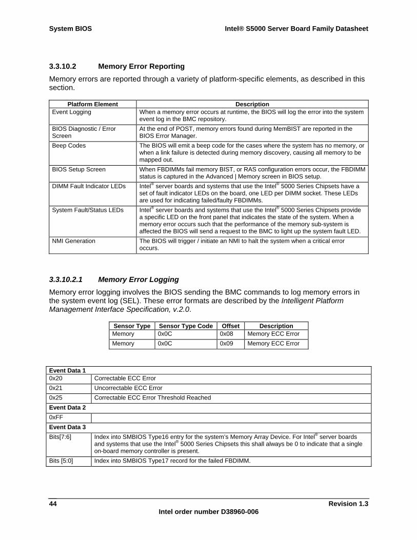
System BIOS Intel® S5000 Server Board Family Datasheet
Revision 1.3 Intel order number D38960-006
44
3.3.10.2 Memory Error Reporting Memory errors are reported through a variety of platform-specific elements, as described in this section.
Platform Element Description Event Logging When a memory error occurs at runtime, the BIOS will log the error into the system
event log in the BMC repository. BIOS Diagnostic / Error Screen
At the end of POST, memory errors found during MemBIST are reported in the BIOS Error Manager.
Beep Codes The BIOS will emit a beep code for the cases where the system has no memory, or when a link failure is detected during memory discovery, causing all memory to be mapped out.
BIOS Setup Screen When FBDIMMs fail memory BIST, or RAS configuration errors occur, the FBDIMM status is captured in the Advanced | Memory screen in BIOS setup.
DIMM Fault Indicator LEDs Intel® server boards and systems that use the Intel® 5000 Series Chipsets have a set of fault indicator LEDs on the board, one LED per DIMM socket. These LEDs are used for indicating failed/faulty FBDIMMs.
System Fault/Status LEDs Intel® server boards and systems that use the Intel® 5000 Series Chipsets provide a specific LED on the front panel that indicates the state of the system. When a memory error occurs such that the performance of the memory sub-system is affected the BIOS will send a request to the BMC to light up the system fault LED.
NMI Generation The BIOS will trigger / initiate an NMI to halt the system when a critical error occurs.
3.3.10.2.1 Memory Error Logging Memory error logging involves the BIOS sending the BMC commands to log memory errors in the system event log (SEL). These error formats are described by the Intelligent Platform Management Interface Specification, v.2.0.
Sensor Type Sensor Type Code Offset Description Memory 0x0C 0x08 Memory ECC Error Memory 0x0C 0x09 Memory ECC Error
Event Data 1 0x20 Correctable ECC Error 0x21 Uncorrectable ECC Error 0x25 Correctable ECC Error Threshold Reached Event Data 2 0xFF Event Data 3 Bits[7:6] Index into SMBIOS Type16 entry for the system’s Memory Array Device. For Intel® server boards
and systems that use the Intel® 5000 Series Chipsets this shall always be 0 to indicate that a single on-board memory controller is present.
Bits [5:0] Index into SMBIOS Type17 record for the failed FBDIMM.
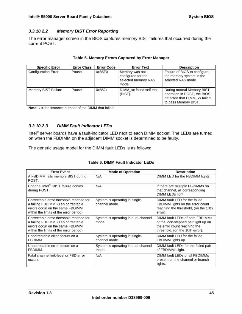
Intel® S5000 Server Board Family Datasheet System BIOS
Revision 1.3 Intel order number D38960-006
45
3.3.10.2.2 Memory BIST Error Reporting The error manager screen in the BIOS captures memory BIST failures that occurred during the current POST.
Table 5. Memory Errors Captured by Error Manager
Specific Error Error Class Error Code Error Text Description Configuration Error Pause 0x85F0 Memory was not
configured for the selected memory RAS mode.
Failure of BIOS to configure the memory system in the selected RAS mode.
Memory BIST Failure Pause 0x852x DIMM_xx failed self test (BIST).
During normal Memory BIST operation in POST, the BIOS detected that DIMM_xx failed to pass Memory BIST.
Note: x = the instance number of the DIMM that failed.
3.3.10.2.3 DIMM Fault Indicator LEDs Intel® server boards have a fault-indicator LED next to each DIMM socket. The LEDs are turned on when the FBDIMM on the adjacent DIMM socket is determined to be faulty.
The generic usage model for the DIMM fault LEDs is as follows:
Table 6. DIMM Fault Indicator LEDs
Error Event Mode of Operation Description A FBDIMM fails memory BIST during POST.
N/A DIMM LED for the FBDIMM lights.
Channel Intel® IBIST failure occurs during POST.
N/A If there are multiple FBDIMMs on that channel, all corresponding DIMM LEDs light.
Correctable error threshold reached for a failing FBDIMM. (Ten correctable errors occur on the same FBDIMM within the limits of the error period)
System is operating in single-channel mode.
DIMM fault LED for the failed FBDIMM lights on the error count reaching the threshold, (on the 10th error).
Correctable error threshold reached for a failing FBDIMM. (Ten correctable errors occur on the same FBDIMM within the limits of the error period)
System is operating in dual-channel mode.
DIMM fault LEDs of both FBDIMMs of the lock-stepped pair light up on the error count reaching the threshold, (on the 10th error).
Uncorrectable error occurs on a FBDIMM.
System is operating in single-channel mode.
DIMM fault LED for the failed FBDIMM lights up.
Uncorrectable error occurs on a FBDIMM.
System is operating in dual-channel mode.
DIMM fault LEDs for the failed pair of FBDIMMs light.
Fatal channel link-level or FBD error occurs.
N/A DIMM fault LEDs of all FBDIMMs present on the channel or branch lights.
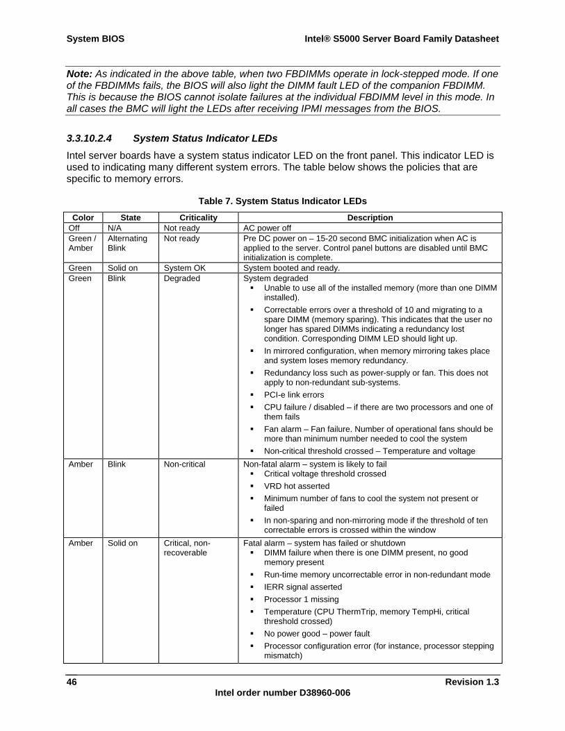
System BIOS Intel® S5000 Server Board Family Datasheet
Revision 1.3 Intel order number D38960-006
46
Note: As indicated in the above table, when two FBDIMMs operate in lock-stepped mode. If one of the FBDIMMs fails, the BIOS will also light the DIMM fault LED of the companion FBDIMM. This is because the BIOS cannot isolate failures at the individual FBDIMM level in this mode. In all cases the BMC will light the LEDs after receiving IPMI messages from the BIOS.
3.3.10.2.4 System Status Indicator LEDs Intel server boards have a system status indicator LED on the front panel. This indicator LED is used to indicating many different system errors. The table below shows the policies that are specific to memory errors.
Table 7. System Status Indicator LEDs
Color State Criticality Description Off N/A Not ready AC power off Green / Amber
Alternating Blink
Not ready Pre DC power on – 15-20 second BMC initialization when AC is applied to the server. Control panel buttons are disabled until BMC initialization is complete.
Green Solid on System OK System booted and ready. Green Blink Degraded System degraded
Unable to use all of the installed memory (more than one DIMM installed).
Correctable errors over a threshold of 10 and migrating to a spare DIMM (memory sparing). This indicates that the user no longer has spared DIMMs indicating a redundancy lost condition. Corresponding DIMM LED should light up.
In mirrored configuration, when memory mirroring takes place and system loses memory redundancy.
Redundancy loss such as power-supply or fan. This does not apply to non-redundant sub-systems.
PCI-e link errors CPU failure / disabled – if there are two processors and one of
them fails Fan alarm – Fan failure. Number of operational fans should be
more than minimum number needed to cool the system Non-critical threshold crossed – Temperature and voltage
Amber Blink Non-critical Non-fatal alarm – system is likely to fail Critical voltage threshold crossed VRD hot asserted Minimum number of fans to cool the system not present or
failed In non-sparing and non-mirroring mode if the threshold of ten
correctable errors is crossed within the window Amber Solid on Critical, non-
recoverable Fatal alarm – system has failed or shutdown
DIMM failure when there is one DIMM present, no good memory present
Run-time memory uncorrectable error in non-redundant mode IERR signal asserted Processor 1 missing Temperature (CPU ThermTrip, memory TempHi, critical
threshold crossed) No power good – power fault Processor configuration error (for instance, processor stepping
mismatch)
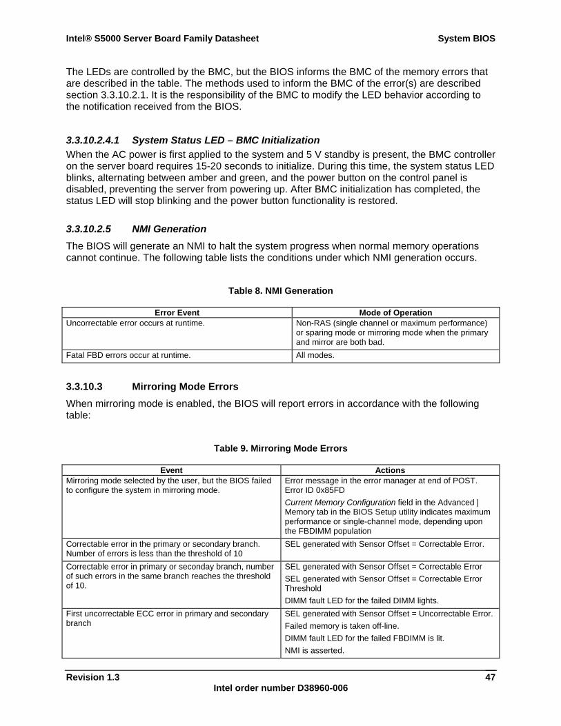
Intel® S5000 Server Board Family Datasheet System BIOS
Revision 1.3 Intel order number D38960-006
47
The LEDs are controlled by the BMC, but the BIOS informs the BMC of the memory errors that are described in the table. The methods used to inform the BMC of the error(s) are described section 3.3.10.2.1. It is the responsibility of the BMC to modify the LED behavior according to the notification received from the BIOS.
3.3.10.2.4.1 System Status LED – BMC Initialization When the AC power is first applied to the system and 5 V standby is present, the BMC controller on the server board requires 15-20 seconds to initialize. During this time, the system status LED blinks, alternating between amber and green, and the power button on the control panel is disabled, preventing the server from powering up. After BMC initialization has completed, the status LED will stop blinking and the power button functionality is restored.
3.3.10.2.5 NMI Generation The BIOS will generate an NMI to halt the system progress when normal memory operations cannot continue. The following table lists the conditions under which NMI generation occurs.
Table 8. NMI Generation
Error Event Mode of Operation Uncorrectable error occurs at runtime. Non-RAS (single channel or maximum performance)
or sparing mode or mirroring mode when the primary and mirror are both bad.
Fatal FBD errors occur at runtime. All modes.
3.3.10.3 Mirroring Mode Errors When mirroring mode is enabled, the BIOS will report errors in accordance with the following table:
Table 9. Mirroring Mode Errors
Event Actions Mirroring mode selected by the user, but the BIOS failed to configure the system in mirroring mode.
Error message in the error manager at end of POST. Error ID 0x85FD Current Memory Configuration field in the Advanced | Memory tab in the BIOS Setup utility indicates maximum performance or single-channel mode, depending upon the FBDIMM population
Correctable error in the primary or secondary branch. Number of errors is less than the threshold of 10
SEL generated with Sensor Offset = Correctable Error.
Correctable error in primary or seconday branch, number of such errors in the same branch reaches the threshold of 10.
SEL generated with Sensor Offset = Correctable Error SEL generated with Sensor Offset = Correctable Error Threshold DIMM fault LED for the failed DIMM lights.
First uncorrectable ECC error in primary and secondary branch
SEL generated with Sensor Offset = Uncorrectable Error. Failed memory is taken off-line. DIMM fault LED for the failed FBDIMM is lit. NMI is asserted.
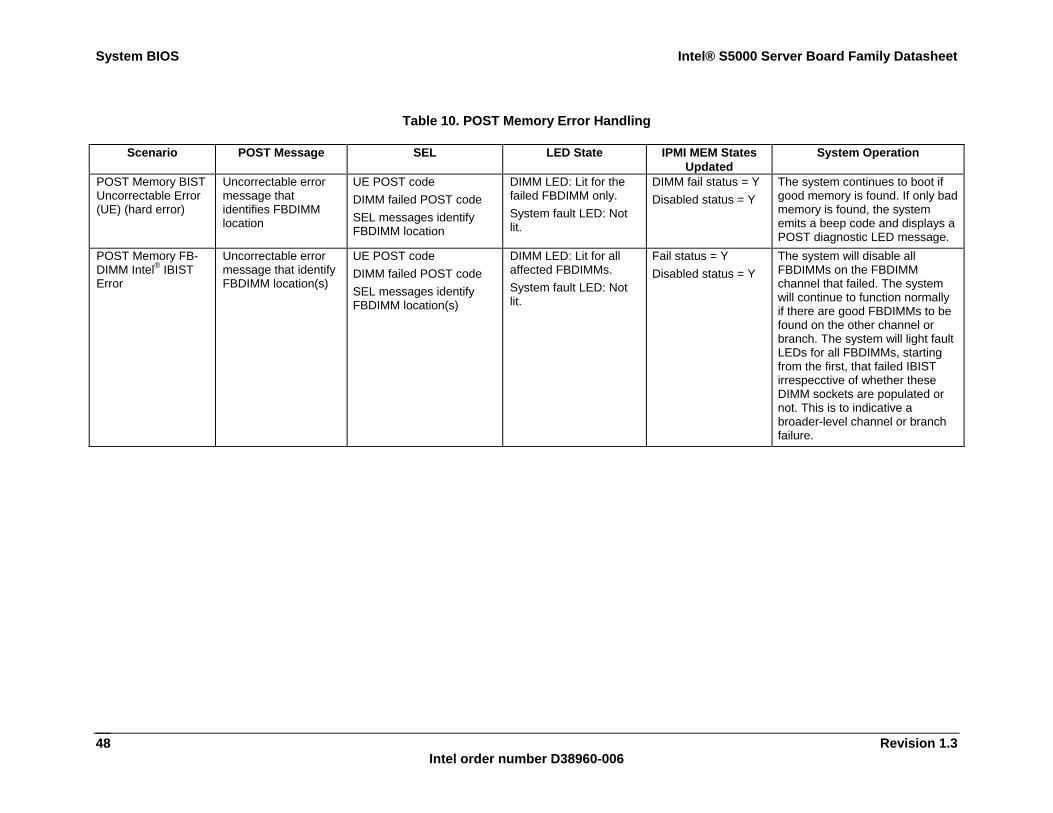
System BIOS Intel® S5000 Server Board Family Datasheet
Revision 1.3 Intel order number D38960-006
48
Table 10. POST Memory Error Handling
Scenario POST Message SEL LED State IPMI MEM States Updated
System Operation
POST Memory BIST Uncorrectable Error (UE) (hard error)
Uncorrectable error message that identifies FBDIMM location
UE POST code DIMM failed POST code SEL messages identify FBDIMM location
DIMM LED: Lit for the failed FBDIMM only. System fault LED: Not lit.
DIMM fail status = Y Disabled status = Y
The system continues to boot if good memory is found. If only bad memory is found, the system emits a beep code and displays a POST diagnostic LED message.
POST Memory FB-DIMM Intel® IBIST Error
Uncorrectable error message that identify FBDIMM location(s)
UE POST code DIMM failed POST code SEL messages identify FBDIMM location(s)
DIMM LED: Lit for all affected FBDIMMs. System fault LED: Not lit.
Fail status = Y Disabled status = Y
The system will disable all FBDIMMs on the FBDIMM channel that failed. The system will continue to function normally if there are good FBDIMMs to be found on the other channel or branch. The system will light fault LEDs for all FBDIMMs, starting from the first, that failed IBIST irrespecctive of whether these DIMM sockets are populated or not. This is to indicative a broader-level channel or branch failure.
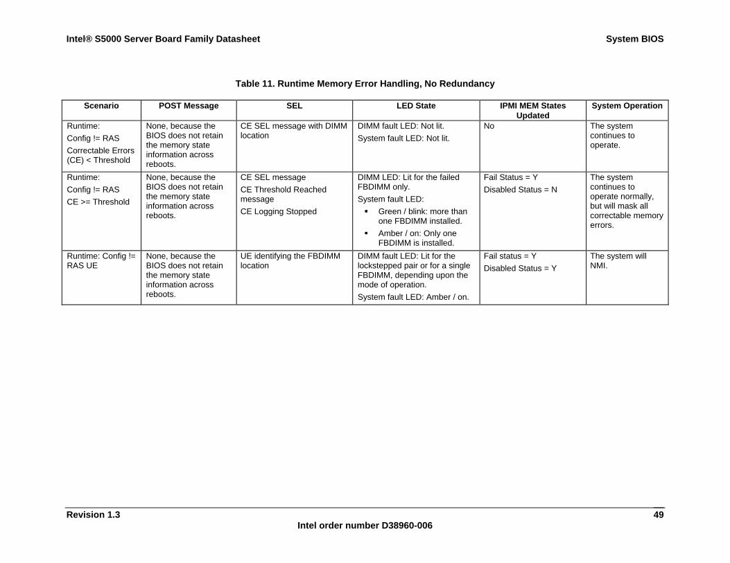
Intel® S5000 Server Board Family Datasheet System BIOS
Revision 1.3 Intel order number D38960-006
49
Table 11. Runtime Memory Error Handling, No Redundancy
Scenario POST Message SEL LED State IPMI MEM States Updated
System Operation
Runtime: Config != RAS Correctable Errors (CE) < Threshold
None, because the BIOS does not retain the memory state information across reboots.
CE SEL message with DIMM location
DIMM fault LED: Not lit. System fault LED: Not lit.
No The system continues to operate.
Runtime: Config != RAS CE >= Threshold
None, because the BIOS does not retain the memory state information across reboots.
CE SEL message CE Threshold Reached message CE Logging Stopped
DIMM LED: Lit for the failed FBDIMM only. System fault LED:
Green / blink: more than one FBDIMM installed.
Amber / on: Only one FBDIMM is installed.
Fail Status = Y Disabled Status = N
The system continues to operate normally, but will mask all correctable memory errors.
Runtime: Config != RAS UE
None, because the BIOS does not retain the memory state information across reboots.
UE identifying the FBDIMM location
DIMM fault LED: Lit for the lockstepped pair or for a single FBDIMM, depending upon the mode of operation. System fault LED: Amber / on.
Fail status = Y Disabled Status = Y
The system will NMI.
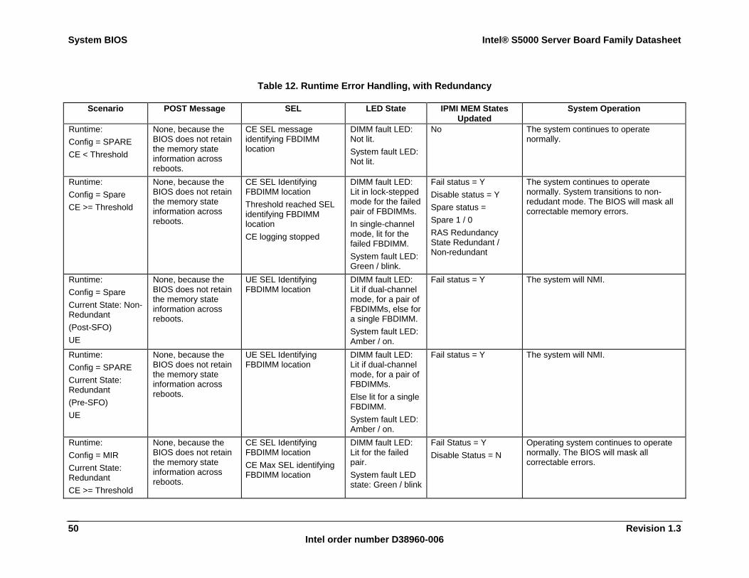
System BIOS Intel® S5000 Server Board Family Datasheet
Revision 1.3 Intel order number D38960-006
50
Table 12. Runtime Error Handling, with Redundancy
Scenario POST Message SEL LED State IPMI MEM States Updated
System Operation
Runtime: Config = SPARE CE < Threshold
None, because the BIOS does not retain the memory state information across reboots.
CE SEL message identifying FBDIMM location
DIMM fault LED: Not lit. System fault LED: Not lit.
No The system continues to operate normally.
Runtime: Config = Spare CE >= Threshold
None, because the BIOS does not retain the memory state information across reboots.
CE SEL Identifying FBDIMM location Threshold reached SEL identifying FBDIMM location CE logging stopped
DIMM fault LED: Lit in lock-stepped mode for the failed pair of FBDIMMs. In single-channel mode, lit for the failed FBDIMM. System fault LED: Green / blink.
Fail status = Y Disable status = Y Spare status = Spare 1 / 0 RAS Redundancy State Redundant / Non-redundant
The system continues to operate normally. System transitions to non-redudant mode. The BIOS will mask all correctable memory errors.
Runtime: Config = Spare Current State: Non-Redundant (Post-SFO) UE
None, because the BIOS does not retain the memory state information across reboots.
UE SEL Identifying FBDIMM location
DIMM fault LED: Lit if dual-channel mode, for a pair of FBDIMMs, else for a single FBDIMM. System fault LED: Amber / on.
Fail status = Y The system will NMI.
Runtime: Config = SPARE Current State: Redundant (Pre-SFO) UE
None, because the BIOS does not retain the memory state information across reboots.
UE SEL Identifying FBDIMM location
DIMM fault LED: Lit if dual-channel mode, for a pair of FBDIMMs. Else lit for a single FBDIMM. System fault LED: Amber / on.
Fail status = Y The system will NMI.
Runtime: Config = MIR Current State: Redundant CE >= Threshold
None, because the BIOS does not retain the memory state information across reboots.
CE SEL Identifying FBDIMM location CE Max SEL identifying FBDIMM location
DIMM fault LED: Lit for the failed pair. System fault LED state: Green / blink
Fail Status = Y Disable Status = N
Operating system continues to operate normally. The BIOS will mask all correctable errors.
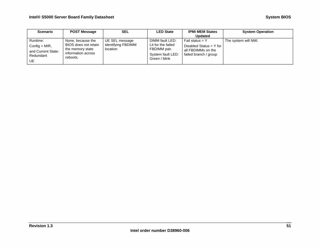
Intel® S5000 Server Board Family Datasheet System BIOS
Revision 1.3 Intel order number D38960-006
51
Scenario POST Message SEL LED State IPMI MEM States Updated
System Operation
Runtime: Config = MIR, and Current State: Redundant UE
None, because the BIOS does not retain the memory state information across reboots.
UE SEL message identifying FBDIMM location
DIMM fault LED: Lit for the failed FBDIMM pair. System fault LED: Green / blink
Fail status = Y Disabled Status = Y for all FBDIMMs on the failed branch / group
The system will NMI.
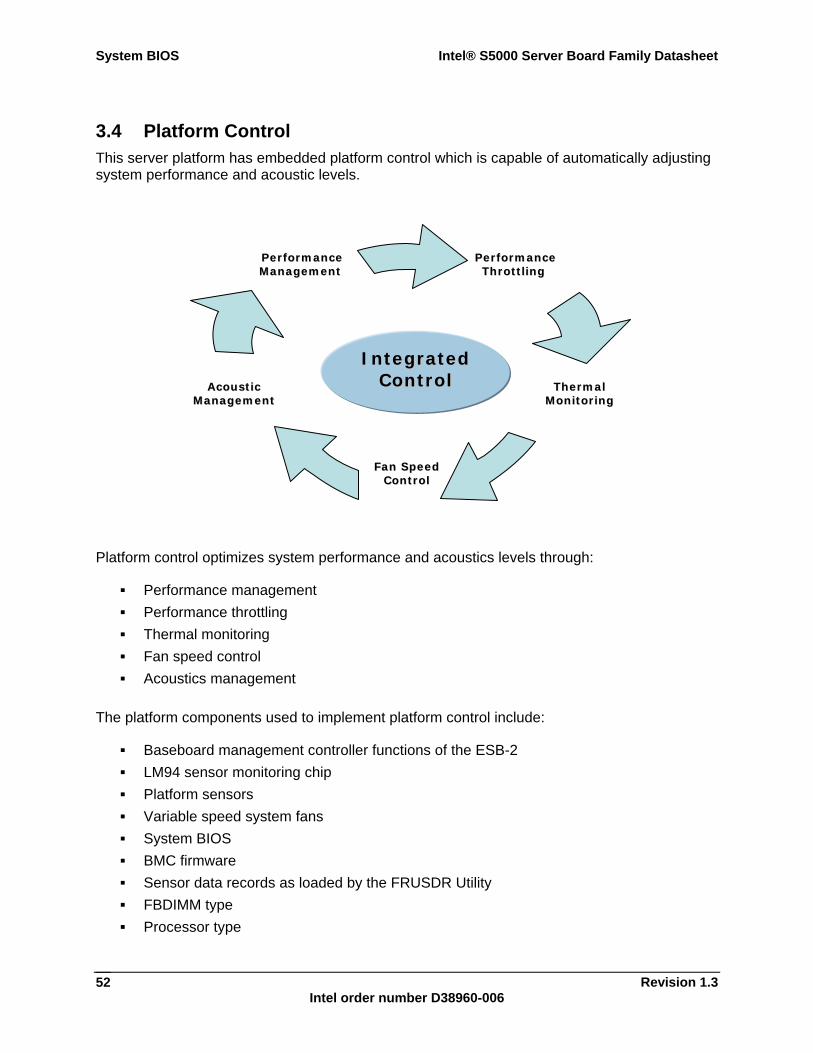
System BIOS Intel® S5000 Server Board Family Datasheet
Revision 1.3 Intel order number D38960-006
52
3.4 Platform Control This server platform has embedded platform control which is capable of automatically adjusting system performance and acoustic levels.
Platform control optimizes system performance and acoustics levels through:
Performance management Performance throttling Thermal monitoring Fan speed control Acoustics management
The platform components used to implement platform control include:
Baseboard management controller functions of the ESB-2 LM94 sensor monitoring chip Platform sensors Variable speed system fans System BIOS BMC firmware Sensor data records as loaded by the FRUSDR Utility FBDIMM type Processor type
FFaann SSppeeeedd CCoonnttrrooll
TThheerrmmaall MMoonniittoorriinngg
PPeerrffoorrmmaannccee TThhrroottttlliinngg
AAccoouussttiicc MMaannaaggeemmeenntt
PPeerrffoorrmmaannccee MMaannaaggeemmeenntt
IInntteeggrraatteedd CCoonnttrrooll
Intel® S5000 Server Board Family Datasheet System BIOS
Revision 1.3 Intel order number D38960-006
53
3.4.1 FBDIMM Open and Closed Loop Thermal Throttling Open-Loop Thermal Throttling (OLTT) Throttling is a solution to cool the DIMMs by reducing memory traffic allowed on the memory bus, which reduces power consumption and thermal output. With OLTT, the system throttles in response to memory bandwidth demands instead of actual memory temperature. Since there is no direct temperature feedback from the Fully Buffered DIMMs (FBD), the throttling behavior is preset rather than conservatively based on the worst cooling conditions (i.e., high inlet temperature and low fan speeds). Additionally, the fans that provide cooling to the memory region is set to conservative settings as well (i.e., higher minimal fan speed). OLTT produces a slightly louder system than CLTT because minimal fan speeds have to be set high enough to support any FBDs in the worst memory cooling conditions. Closed-Loop Thermal Throttling (CLTT) CLTT works by throttling the FBDs response directly to memory temperature via thermal sensors integrated on the advance memory buffer (AMB) of the FBD. This is the preferred throttling method because this approach lowers limitations on both memory power and thermal threshold, therefore minimizing throttling impact on memory performance. This reduces the utilization of high fan speeds because CLTT does not have to accommodated for the worst memory cooling conditions; with a higher thermal threshold, CLTT enables memory performance to achieve optimal levels. If the thermal sensors do not function properly (i.e, unable to retrieve memory temperature readings), the system can respond accordingly to enable either OLTT or CLTT.
Note: CLTT is only supported starting for specific BIOS, BMC and FRUSDR versions. See the Release Notes for information on the software stack that applies to your product(s).
3.4.2 Fan Speed Control System fan speed is controlled by the Baseboard Management Controller (BMC) functions of the ESB-2 chip. During normal system operation, the BMC will retrieve information from BIOS and monitor several platform thermal sensors to determine the required fan speeds.
In order to provide the proper fan speed control for a given system configuration, the BMC must have the appropriate platform data programmed. Platform configuration data is programmed using the FRUSDR Utility during the system integration process, and by System BIOS during run time.
3.4.2.1 System Configuration Using the FRUSDR Utility The Field Replaceable Unit & Sensor Data Record Update Utility (FRUSDR utility) is a program used to write platform specific configuration data to NVRAM on the server board. It allows the User to select which supported chassis (Intel or Non-Intel) and platform chassis configuration is being used. Based on the input provided, the FRUSDR writes sensor data specific to the configuration to NVRAM for the BMC controller to read each time the system is powered on.
3.4.2.2 Fan Speed Control from BMC and BIOS Inputs Using the data programmed to NVRAM by the FRUSDR utility, the BMC is configured to monitor and control the appropriate platform sensors and system fans each time the system is powered on. After power-on, the BMC uses additional data provided to it by System BIOS to determine how the system fans should be controlled.
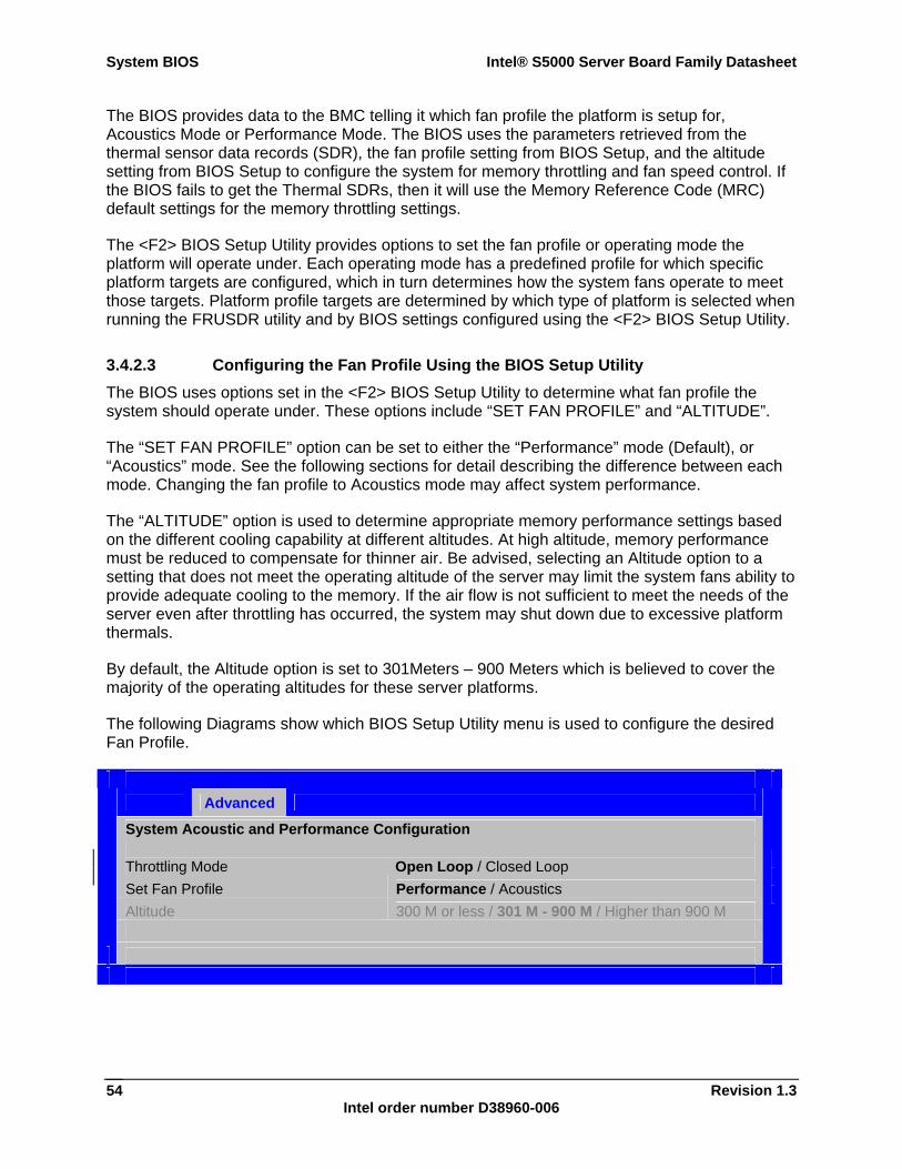
System BIOS Intel® S5000 Server Board Family Datasheet
Revision 1.3 Intel order number D38960-006
54
The BIOS provides data to the BMC telling it which fan profile the platform is setup for, Acoustics Mode or Performance Mode. The BIOS uses the parameters retrieved from the thermal sensor data records (SDR), the fan profile setting from BIOS Setup, and the altitude setting from BIOS Setup to configure the system for memory throttling and fan speed control. If the BIOS fails to get the Thermal SDRs, then it will use the Memory Reference Code (MRC) default settings for the memory throttling settings.
The <F2> BIOS Setup Utility provides options to set the fan profile or operating mode the platform will operate under. Each operating mode has a predefined profile for which specific platform targets are configured, which in turn determines how the system fans operate to meet those targets. Platform profile targets are determined by which type of platform is selected when running the FRUSDR utility and by BIOS settings configured using the <F2> BIOS Setup Utility.
3.4.2.3 Configuring the Fan Profile Using the BIOS Setup Utility The BIOS uses options set in the <F2> BIOS Setup Utility to determine what fan profile the system should operate under. These options include “SET FAN PROFILE” and “ALTITUDE”.
The “SET FAN PROFILE” option can be set to either the “Performance” mode (Default), or “Acoustics” mode. See the following sections for detail describing the difference between each mode. Changing the fan profile to Acoustics mode may affect system performance.
The “ALTITUDE” option is used to determine appropriate memory performance settings based on the different cooling capability at different altitudes. At high altitude, memory performance must be reduced to compensate for thinner air. Be advised, selecting an Altitude option to a setting that does not meet the operating altitude of the server may limit the system fans ability to provide adequate cooling to the memory. If the air flow is not sufficient to meet the needs of the server even after throttling has occurred, the system may shut down due to excessive platform thermals.
By default, the Altitude option is set to 301Meters – 900 Meters which is believed to cover the majority of the operating altitudes for these server platforms.
The following Diagrams show which BIOS Setup Utility menu is used to configure the desired Fan Profile.
Advanced
System Acoustic and Performance Configuration Throttling Mode Open Loop / Closed Loop Set Fan Profile Performance / Acoustics Altitude 300 M or less / 301 M - 900 M / Higher than 900 M
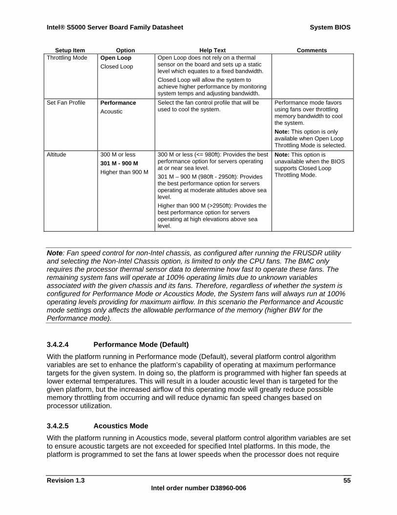
Intel® S5000 Server Board Family Datasheet System BIOS
Revision 1.3 Intel order number D38960-006
55
Setup Item Option Help Text Comments Throttling Mode Open Loop
Closed Loop Open Loop does not rely on a thermal sensor on the board and sets up a static level which equates to a fixed bandwidth. Closed Loop will allow the system to achieve higher performance by monitoring system temps and adjusting bandwidth.
Set Fan Profile Performance Acoustic
Select the fan control profile that will be used to cool the system.
Performance mode favors using fans over throttling memory bandwidth to cool the system. Note: This option is only available when Open Loop Throttling Mode is selected.
Altitude 300 M or less 301 M - 900 M Higher than 900 M
300 M or less (<= 980ft): Provides the best performance option for servers operating at or near sea level. 301 M – 900 M (980ft - 2950ft): Provides the best performance option for servers operating at moderate altitudes above sea level. Higher than 900 M (>2950ft): Provides the best performance option for servers operating at high elevations above sea level.
Note: This option is unavailable when the BIOS supports Closed Loop Throttling Mode.
Note: Fan speed control for non-Intel chassis, as configured after running the FRUSDR utility and selecting the Non-Intel Chassis option, is limited to only the CPU fans. The BMC only requires the processor thermal sensor data to determine how fast to operate these fans. The remaining system fans will operate at 100% operating limits due to unknown variables associated with the given chassis and its fans. Therefore, regardless of whether the system is configured for Performance Mode or Acoustics Mode, the System fans will always run at 100% operating levels providing for maximum airflow. In this scenario the Performance and Acoustic mode settings only affects the allowable performance of the memory (higher BW for the Performance mode).
3.4.2.4 Performance Mode (Default) With the platform running in Performance mode (Default), several platform control algorithm variables are set to enhance the platform’s capability of operating at maximum performance targets for the given system. In doing so, the platform is programmed with higher fan speeds at lower external temperatures. This will result in a louder acoustic level than is targeted for the given platform, but the increased airflow of this operating mode will greatly reduce possible memory throttling from occurring and will reduce dynamic fan speed changes based on processor utilization.
3.4.2.5 Acoustics Mode With the platform running in Acoustics mode, several platform control algorithm variables are set to ensure acoustic targets are not exceeded for specified Intel platforms. In this mode, the platform is programmed to set the fans at lower speeds when the processor does not require
System BIOS Intel® S5000 Server Board Family Datasheet
Revision 1.3 Intel order number D38960-006
56
additional cooling due to high utilization / power consumption. Memory throttling will be utilized to ensure that the memory thermal limits are not exceeded.
3.5 Flash ROM The BIOS supports the Intel® 28F320C3 flash part. The flash part is a 4 MB flash ROM, 2 MB of which is programmable. The flash ROM contains system initialization routines, setup utility, and runtime support routines. The exact layout is subject to change, as determined by Intel. A 128 KB block is available for storing OEM code (user binary) and custom logos.
3.6 BIOS User Interface 3.6.1 Logo / Diagnostic Screen The Logo / Diagnostic screen may be in one of two forms. If Display Logo is enabled in the BIOS Setup utility, a logo splash screen is displayed. By default Display Logo is enabled in BIOS Setup. If the logo is displayed during POST, pressing <Esc> will hide the logo and display the diagnostic screen.
If no logo is present in the flash ROM, or if Display Logo is disabled in the system configuration, the summary and diagnostic screen is displayed.
The diagnostic screen consists of the following information:
BIOS ID. See Section 3.1 System name Total memory detected (the total size of all installed FBDIMMs) Processor information (Intel branded string, speed, and number of physical processors
identified) Flash bank from which the system is booted Types of keyboards detected if plugged in (PS/2* and/or USB) Types of mouse devices detected if plugged in (PS/2 and/or USB)
3.7 BIOS Setup Utility The BIOS Setup utility is a text-based utility that allows the user to configure the system and view current settings and environment information for the platform devices. The BIOS Setup utility controls the platform's built-in devices.
The BIOS Setup utility interface consists of a number of pages or screens. Each page contains information or links to other pages. The first page in the BIOS Setup utility displays a list of general categories as links. These links lead to pages containing specific category’s configuration.
The following sections describe the look and behavior for the BIOS Setup utility.
3.7.1 Operation The BIOS Setup utility has the following features:
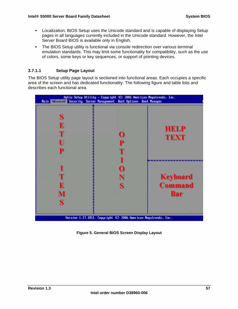
Intel® S5000 Server Board Family Datasheet System BIOS
Revision 1.3 Intel order number D38960-006
57
Localization. BIOS Setup uses the Unicode standard and is capable of displaying Setup pages in all languages currently included in the Unicode standard. However, the Intel Server Board BIOS is available only in English.
The BIOS Setup utility is functional via console redirection over various terminal emulation standards. This may limit some functionality for compatibility, such as the use of colors, some keys or key sequences, or support of pointing devices.
3.7.1.1 Setup Page Layout The BIOS Setup utility page layout is sectioned into functional areas. Each occupies a specific area of the screen and has dedicated functionality. The following figure and table lists and describes each functional area.
Figure 5. General BIOS Screen Display Layout
System BIOS Intel® S5000 Server Board Family Datasheet
Revision 1.3 Intel order number D38960-006
58
Table 13. BIOS Setup Page Layout
Functional Area Description Title Bar The title bar is located at the top of the screen and displays the title of the form
(page) the user is currently viewing. It may also display navigational information. Setup Item List The setup item list is a set of controllable and informational items. Each item in the
list occupies the left and center columns in the middle of the screen. The left column, the setup item, is the subject of the item. The middle column, the option, contains an informational value or choices of the subject. A setup item can be a hyperlink that is used to navigate pages. When it is a hyperlink, a setup item only occupies the setup item part of the screen.
Item Specific Help Area The item specific help area is located on the right side of the screen and contains help text for the highlighted setup item. Help information includes the meaning and usage of the item, allowable values, effects of the options, etc.
Keyboard Command Bar The keyboard command bar at the bottom right of the screen continuously displays help for special keys and navigation keys. The keyboard command bar is context-sensitive—it displays keys relevant to current page and mode.
Status Bar The status bar occupies the bottom line of the screen. This line would displays the BIOS ID.
3.7.1.2 Entering BIOS Setup The BIOS Setup utility is started by pressing the <F2> key during the system boot when the OEM or Intel logo is displayed.
When Display Logo is disabled, the following message is displayed on the diagnostics screen: “press <F2> to enter setup”.
3.7.1.3 Keyboard Commands The bottom right portion of the BIOS Setup utility screen provides a list of commands that are used to navigate through the utility. These commands are displayed at all times.
Each menu page contains a number of features. Except those used for informative purposes, each feature is associated with a value field. This field contains user-selectable parameters. Depending on the security option chosen and in effect by the password, a menu feature’s value may or may not be changeable. If a value is non-changeable, the feature’s value field is inaccessible. It displays as “grayed out.”
Intel® S5000 Server Board Family Datasheet System BIOS
Revision 1.3 Intel order number D38960-006
59
The keyboard command bar supports the following:
Table 14. BIOS Setup: Keyboard Command Bar
Key Option Description <Enter> Execute
Command The <Enter> key is used to activate sub-menus when the selected feature is a sub-menu, or to display a pick list if a selected option has a value field, or to select a sub-field for multi-valued features like time and date. If a pick list is displayed, the <Enter> key will select the currently highlighted item, undo the pick list, and return the focus to the parent menu.
<Esc> Exit The <Esc> key provides a mechanism for backing out of any field. This key will undo the pressing of the Enter key. When the <Esc> key is pressed while editing any field or selecting features of a menu, the parent menu is re-entered. When the <Esc> key is pressed in any sub-menu, the parent menu is re-entered. When the <Esc> key is pressed in any major menu, the exit confirmation window is displayed and the user is asked whether changes can be discarded. If “No” is selected and the <Enter> key is pressed, or if the <Esc> key is pressed, the user is returned to where he/she was before <Esc> was pressed, without affecting any existing any settings. If “Yes” is selected and the <Enter> key is pressed, setup is exited and the BIOS returns to the main System Options Menu screen.
↑ Select Item The up arrow is used to select the previous value in a pick list, or the previous option in a menu item's option list. The selected item must then be activated by pressing the <Enter> key.
↓ Select Item The down arrow is used to select the next value in a menu item’s option list, or a value field’s pick list. The selected item must then be activated by pressing the <Enter> key.
↔ Select Menu The left and right arrow keys are used to move between the major menu pages. The keys have no affect if a sub-menu or pick list is displayed.
<Tab> Select Field The <Tab> key is used to move between fields. For example, <Tab> can be used to move from hours to minutes in the time item in the main menu.
- Change Value The minus key on the keypad is used to change the value of the current item to the previous value. This key scrolls through the values in the associated pick list without displaying the full list.
+ Change Value The plus key on the keypad is used to change the value of the current menu item to the next value. This key scrolls through the values in the associated pick list without displaying the full list. On 106-key Japanese keyboards, the plus key has a different scan code than the plus key on the other keyboard, but will have the same effect.
<F9> Setup Defaults Pressing the <F9> key causes the following to appear:
Load Optimized defaults? (Y/N) If the <Y> key is pressed, all Setup fields are set to their default values. If the <N> key is pressed, or if the <Esc> key is pressed, the user is returned to where they were before the <F9> key was pressed without affecting any existing field values
<F10> Save and Exit Pressing the <F10> key causes the following message to appear:
Save Configuration and Reset? (Y/N) If the <Y> key is pressed, all changes are saved and Setup is exited. If the <N> key is pressed, or the <Esc> key is pressed, the user is returned to where they were before the <F10> key was pressed without affecting any existing values.
System BIOS Intel® S5000 Server Board Family Datasheet
Revision 1.3 Intel order number D38960-006
60
3.7.1.4 Menu Selection Bar The menu selection bar is located at the top of the screen. It displays the major menu selections.
3.7.2 Server Platform Setup Screens The sections below describe the screens available for the configuration of a server platform. In these sections, tables and figures are used to describe the contents of each screen. These tables and figures follow the following guidelines:
The text and values in the Setup Item, Options, and Help columns are displayed on the BIOS Setup screens.
Text in bold text in the Options columns indicates default values. These values are not displayed in bold on the setup screen.
Text in the Options columns indicates options available. The Comments column provides additional information where it may be helpful. This
information does not appear in the BIOS Setup screens. Information in the screen shot figures that is enclosed in brackets (< >) indicates text
that varies, depending on the option(s) installed. For example <Current Date> is replaced by the actual current date.
Information that is enclosed in ellipses brackets ({ }) in the tables indicates areas where the user needs to type in text instead of selecting from a provided option.
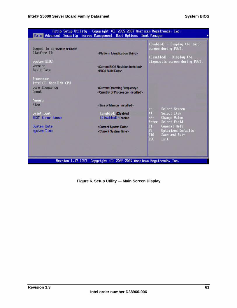
Intel® S5000 Server Board Family Datasheet System BIOS
Revision 1.3 Intel order number D38960-006
61
Figure 6. Setup Utility — Main Screen Display
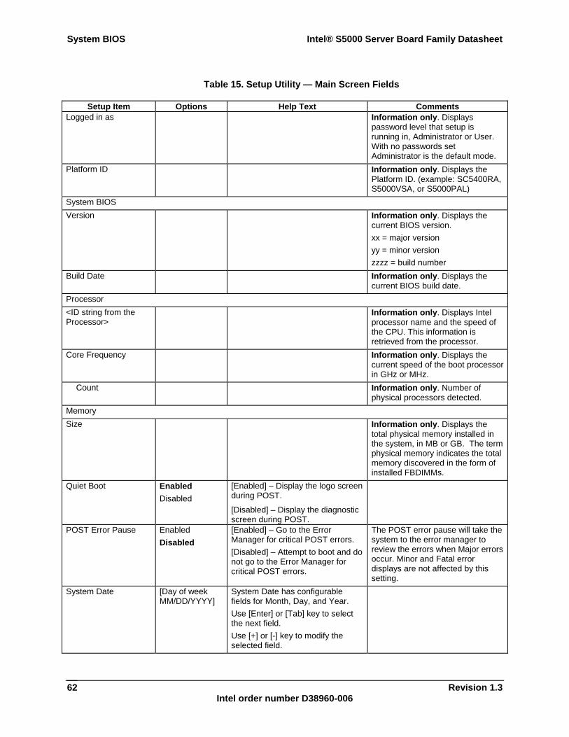
System BIOS Intel® S5000 Server Board Family Datasheet
Revision 1.3 Intel order number D38960-006
62
Table 15. Setup Utility — Main Screen Fields
Setup Item Options Help Text Comments Logged in as Information only. Displays
password level that setup is running in, Administrator or User. With no passwords set Administrator is the default mode.
Platform ID Information only. Displays the Platform ID. (example: SC5400RA, S5000VSA, or S5000PAL)
System BIOS Version Information only. Displays the
current BIOS version. xx = major version yy = minor version zzzz = build number
Build Date Information only. Displays the current BIOS build date.
Processor <ID string from the Processor>
Information only. Displays Intel processor name and the speed of the CPU. This information is retrieved from the processor.
Core Frequency Information only. Displays the current speed of the boot processor in GHz or MHz.
Count Information only. Number of physical processors detected.
Memory Size Information only. Displays the
total physical memory installed in the system, in MB or GB. The term physical memory indicates the total memory discovered in the form of installed FBDIMMs.
Quiet Boot Enabled Disabled
[Enabled] – Display the logo screen during POST.
[Disabled] – Display the diagnostic screen during POST.
POST Error Pause Enabled Disabled
[Enabled] – Go to the Error Manager for critical POST errors. [Disabled] – Attempt to boot and do not go to the Error Manager for critical POST errors.
The POST error pause will take the system to the error manager to review the errors when Major errors occur. Minor and Fatal error displays are not affected by this setting.
System Date [Day of week MM/DD/YYYY]
System Date has configurable fields for Month, Day, and Year. Use [Enter] or [Tab] key to select the next field. Use [+] or [-] key to modify the selected field.
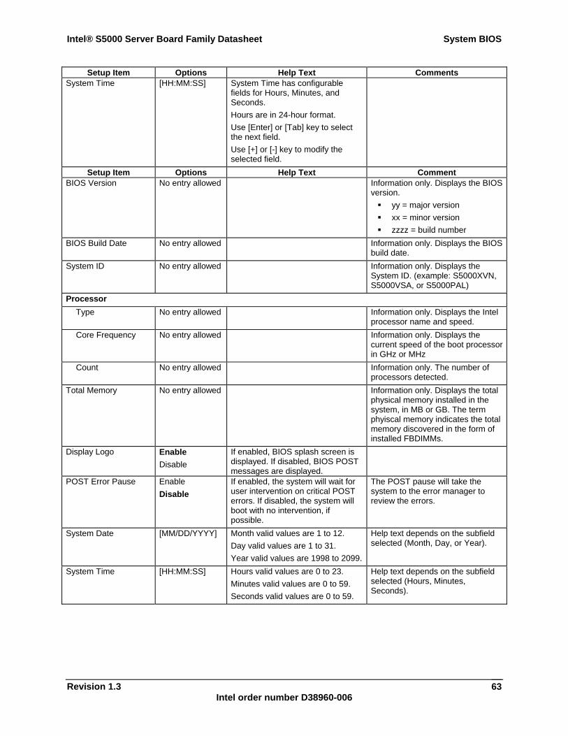
Intel® S5000 Server Board Family Datasheet System BIOS
Revision 1.3 Intel order number D38960-006
63
Setup Item Options Help Text Comments System Time [HH:MM:SS] System Time has configurable
fields for Hours, Minutes, and Seconds. Hours are in 24-hour format. Use [Enter] or [Tab] key to select the next field. Use [+] or [-] key to modify the selected field.
Setup Item Options Help Text Comment BIOS Version No entry allowed Information only. Displays the BIOS
version. yy = major version xx = minor version zzzz = build number
BIOS Build Date No entry allowed Information only. Displays the BIOS build date.
System ID No entry allowed Information only. Displays the System ID. (example: S5000XVN, S5000VSA, or S5000PAL)
Processor Type No entry allowed Information only. Displays the Intel
processor name and speed. Core Frequency No entry allowed Information only. Displays the
current speed of the boot processor in GHz or MHz
Count No entry allowed Information only. The number of processors detected.
Total Memory No entry allowed Information only. Displays the total physical memory installed in the system, in MB or GB. The term phyiscal memory indicates the total memory discovered in the form of installed FBDIMMs.
Display Logo Enable Disable
If enabled, BIOS splash screen is displayed. If disabled, BIOS POST messages are displayed.
POST Error Pause Enable Disable
If enabled, the system will wait for user intervention on critical POST errors. If disabled, the system will boot with no intervention, if possible.
The POST pause will take the system to the error manager to review the errors.
System Date [MM/DD/YYYY] Month valid values are 1 to 12. Day valid values are 1 to 31. Year valid values are 1998 to 2099.
Help text depends on the subfield selected (Month, Day, or Year).
System Time [HH:MM:SS] Hours valid values are 0 to 23. Minutes valid values are 0 to 59. Seconds valid values are 0 to 59.
Help text depends on the subfield selected (Hours, Minutes, Seconds).
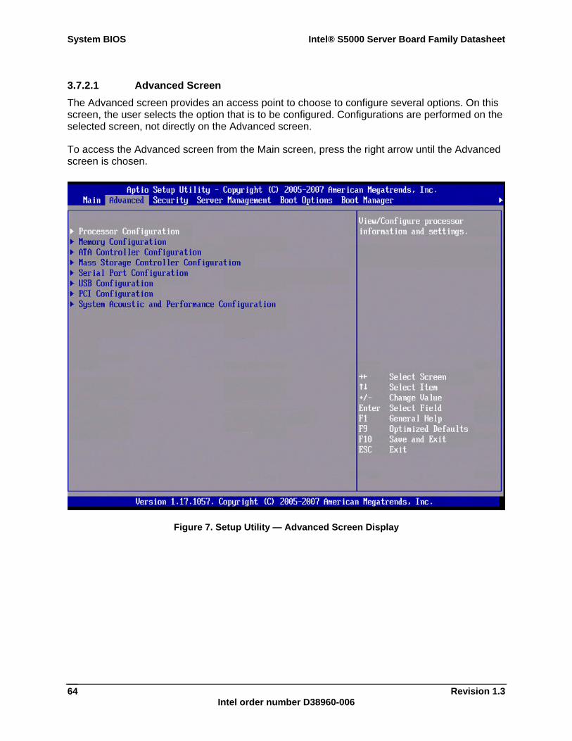
System BIOS Intel® S5000 Server Board Family Datasheet
Revision 1.3 Intel order number D38960-006
64
3.7.2.1 Advanced Screen The Advanced screen provides an access point to choose to configure several options. On this screen, the user selects the option that is to be configured. Configurations are performed on the selected screen, not directly on the Advanced screen.
To access the Advanced screen from the Main screen, press the right arrow until the Advanced screen is chosen.
Figure 7. Setup Utility — Advanced Screen Display
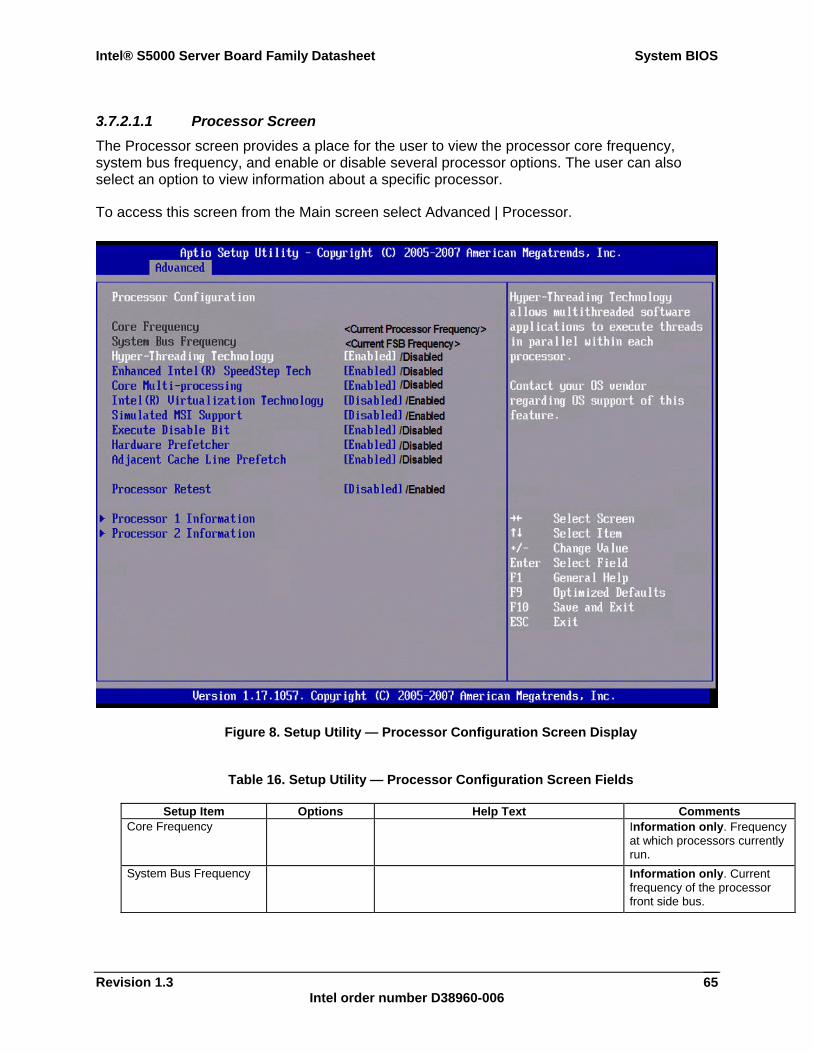
Intel® S5000 Server Board Family Datasheet System BIOS
Revision 1.3 Intel order number D38960-006
65
3.7.2.1.1 Processor Screen The Processor screen provides a place for the user to view the processor core frequency, system bus frequency, and enable or disable several processor options. The user can also select an option to view information about a specific processor.
To access this screen from the Main screen select Advanced | Processor.
Figure 8. Setup Utility — Processor Configuration Screen Display
Table 16. Setup Utility — Processor Configuration Screen Fields
Setup Item Options Help Text Comments Core Frequency Information only. Frequency
at which processors currently run.
System Bus Frequency Information only. Current frequency of the processor front side bus.
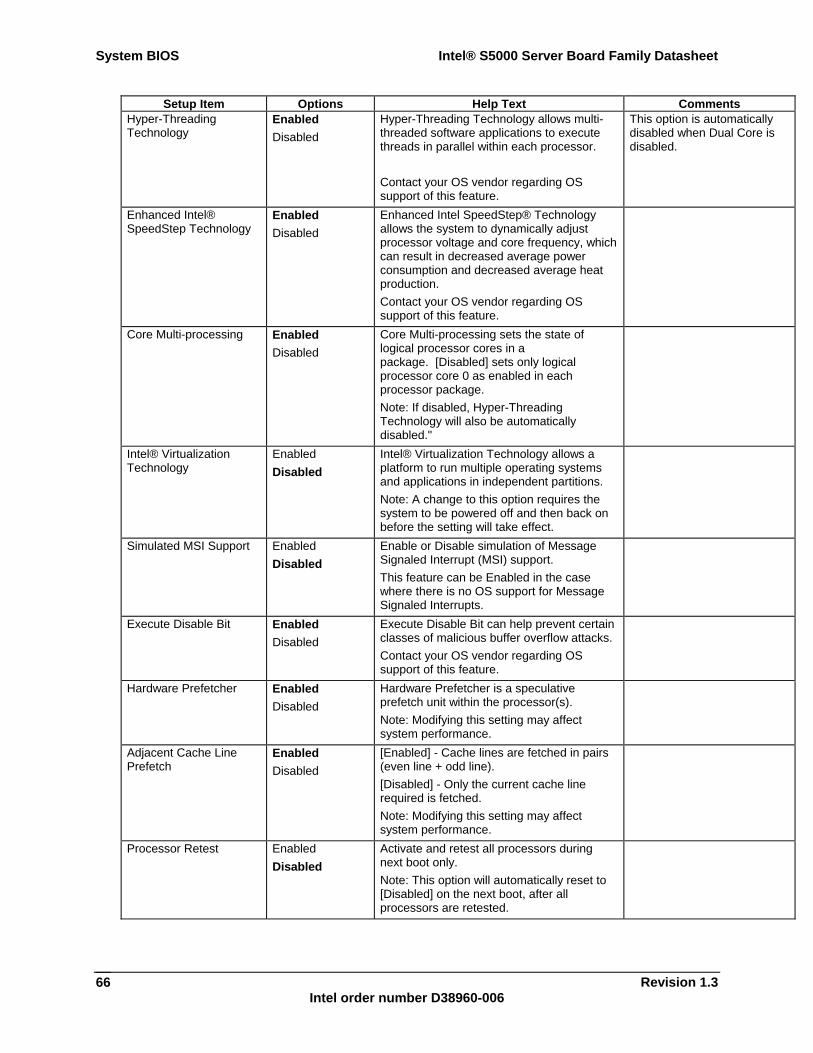
System BIOS Intel® S5000 Server Board Family Datasheet
Revision 1.3 Intel order number D38960-006
66
Setup Item Options Help Text Comments Hyper-Threading Technology
Enabled Disabled
Hyper-Threading Technology allows multi-threaded software applications to execute threads in parallel within each processor. Contact your OS vendor regarding OS support of this feature.
This option is automatically disabled when Dual Core is disabled.
Enhanced Intel® SpeedStep Technology
Enabled Disabled
Enhanced Intel SpeedStep® Technology allows the system to dynamically adjust processor voltage and core frequency, which can result in decreased average power consumption and decreased average heat production. Contact your OS vendor regarding OS support of this feature.
Core Multi-processing Enabled Disabled
Core Multi-processing sets the state of logical processor cores in a package. [Disabled] sets only logical processor core 0 as enabled in each processor package. Note: If disabled, Hyper-Threading Technology will also be automatically disabled."
Intel® Virtualization Technology
Enabled Disabled
Intel® Virtualization Technology allows a platform to run multiple operating systems and applications in independent partitions. Note: A change to this option requires the system to be powered off and then back on before the setting will take effect.
Simulated MSI Support Enabled Disabled
Enable or Disable simulation of Message Signaled Interrupt (MSI) support. This feature can be Enabled in the case where there is no OS support for Message Signaled Interrupts.
Execute Disable Bit Enabled Disabled
Execute Disable Bit can help prevent certain classes of malicious buffer overflow attacks. Contact your OS vendor regarding OS support of this feature.
Hardware Prefetcher Enabled Disabled
Hardware Prefetcher is a speculative prefetch unit within the processor(s). Note: Modifying this setting may affect system performance.
Adjacent Cache Line Prefetch
Enabled Disabled
[Enabled] - Cache lines are fetched in pairs (even line + odd line). [Disabled] - Only the current cache line required is fetched. Note: Modifying this setting may affect system performance.
Processor Retest Enabled Disabled
Activate and retest all processors during next boot only. Note: This option will automatically reset to [Disabled] on the next boot, after all processors are retested.
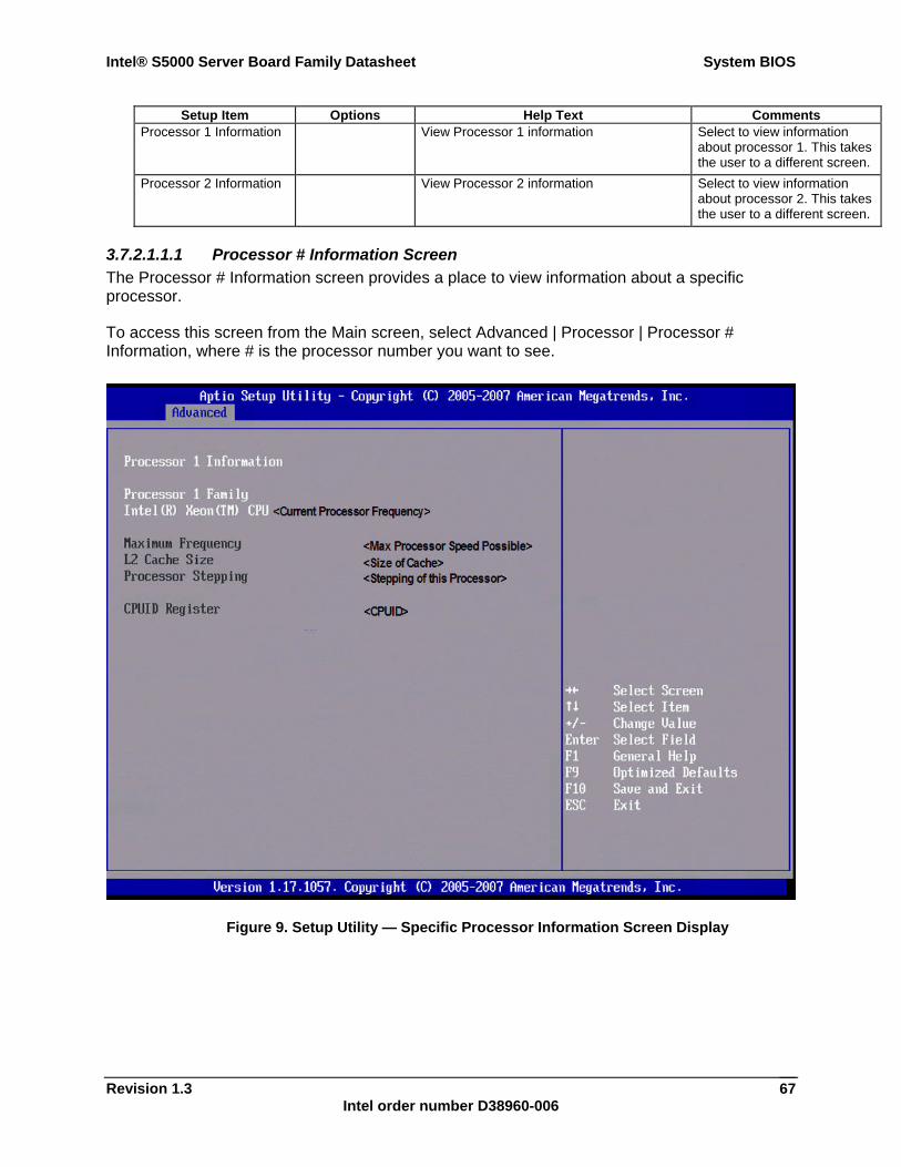
Intel® S5000 Server Board Family Datasheet System BIOS
Revision 1.3 Intel order number D38960-006
67
Setup Item Options Help Text Comments Processor 1 Information View Processor 1 information Select to view information
about processor 1. This takes the user to a different screen.
Processor 2 Information View Processor 2 information Select to view information about processor 2. This takes the user to a different screen.
3.7.2.1.1.1 Processor # Information Screen The Processor # Information screen provides a place to view information about a specific processor.
To access this screen from the Main screen, select Advanced | Processor | Processor # Information, where # is the processor number you want to see.
Figure 9. Setup Utility — Specific Processor Information Screen Display
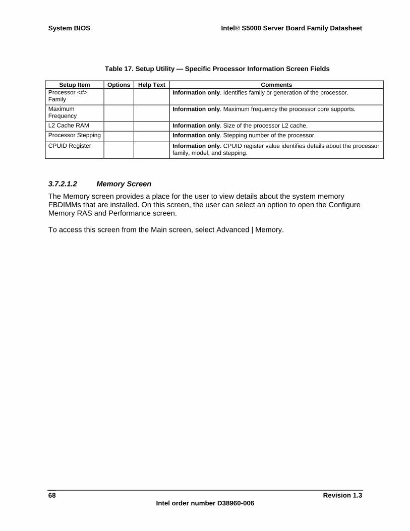
System BIOS Intel® S5000 Server Board Family Datasheet
Revision 1.3 Intel order number D38960-006
68
Table 17. Setup Utility — Specific Processor Information Screen Fields
Setup Item Options Help Text Comments Processor <#> Family
Information only. Identifies family or generation of the processor.
Maximum Frequency
Information only. Maximum frequency the processor core supports.
L2 Cache RAM Information only. Size of the processor L2 cache. Processor Stepping Information only. Stepping number of the processor.
CPUID Register Information only. CPUID register value identifies details about the processor family, model, and stepping.
3.7.2.1.2 Memory Screen The Memory screen provides a place for the user to view details about the system memory FBDIMMs that are installed. On this screen, the user can select an option to open the Configure Memory RAS and Performance screen.
To access this screen from the Main screen, select Advanced | Memory.
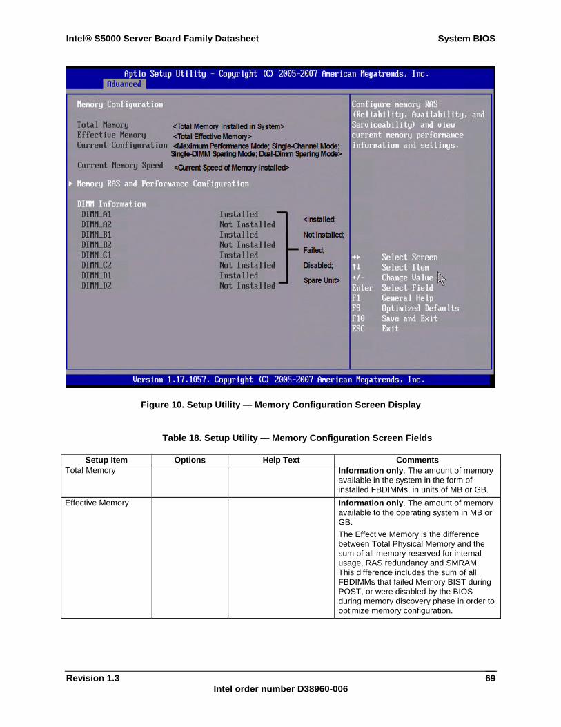
Intel® S5000 Server Board Family Datasheet System BIOS
Revision 1.3 Intel order number D38960-006
69
Figure 10. Setup Utility — Memory Configuration Screen Display
Table 18. Setup Utility — Memory Configuration Screen Fields
Setup Item Options Help Text Comments Total Memory Information only. The amount of memory
available in the system in the form of installed FBDIMMs, in units of MB or GB.
Effective Memory Information only. The amount of memory available to the operating system in MB or GB. The Effective Memory is the difference between Total Physical Memory and the sum of all memory reserved for internal usage, RAS redundancy and SMRAM. This difference includes the sum of all FBDIMMs that failed Memory BIST during POST, or were disabled by the BIOS during memory discovery phase in order to optimize memory configuration.
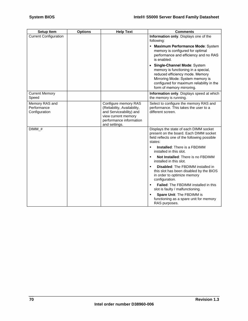
System BIOS Intel® S5000 Server Board Family Datasheet
Revision 1.3 Intel order number D38960-006
70
Setup Item Options Help Text Comments Current Configuration Information only. Displays one of the
following: Maximum Performance Mode: System
memory is configured for optimal performance and efficiency and no RAS is enabled.
• Single-Channel Mode: System memory is functioning in a special, reduced efficiency mode. Memory Mirroring Mode: System memory is configured for maximum reliability in the form of memory mirroring.
Current Memory Speed
Information only. Displays speed at which the memory is running.
Memory RAS and Performance Configuration
Configure memory RAS (Reliability, Availability, and Serviceability) and view current memory performance information and settings.
Select to configure the memory RAS and performance. This takes the user to a different screen.
DIMM_# Displays the state of each DIMM socket present on the board. Each DIMM socket field reflects one of the following possible states: Installed: There is a FBDIMM
installed in this slot. Not Installed: There is no FBDIMM
installed in this slot. Disabled: The FBDIMM installed in
this slot has been disabled by the BIOS in order to optimize memory configuration.
Failed: The FBDIMM installed in this slot is faulty / malfunctioning.
Spare Unit: The FBDIMM is functioning as a spare unit for memory RAS purposes.
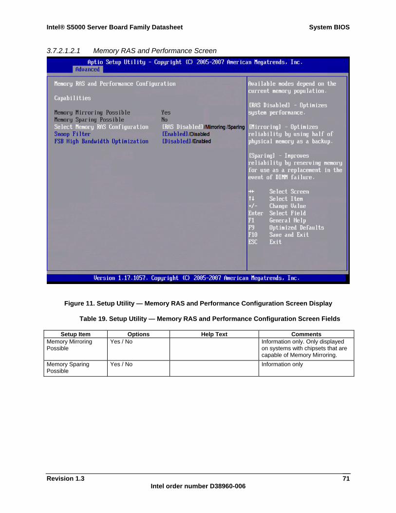
Intel® S5000 Server Board Family Datasheet System BIOS
Revision 1.3 Intel order number D38960-006
71
3.7.2.1.2.1 Memory RAS and Performance Screen
Figure 11. Setup Utility — Memory RAS and Performance Configuration Screen Display
Table 19. Setup Utility — Memory RAS and Performance Configuration Screen Fields
Setup Item Options Help Text Comments Memory Mirroring Possible
Yes / No Information only. Only displayed on systems with chipsets that are capable of Memory Mirroring.
Memory Sparing Possible
Yes / No Information only
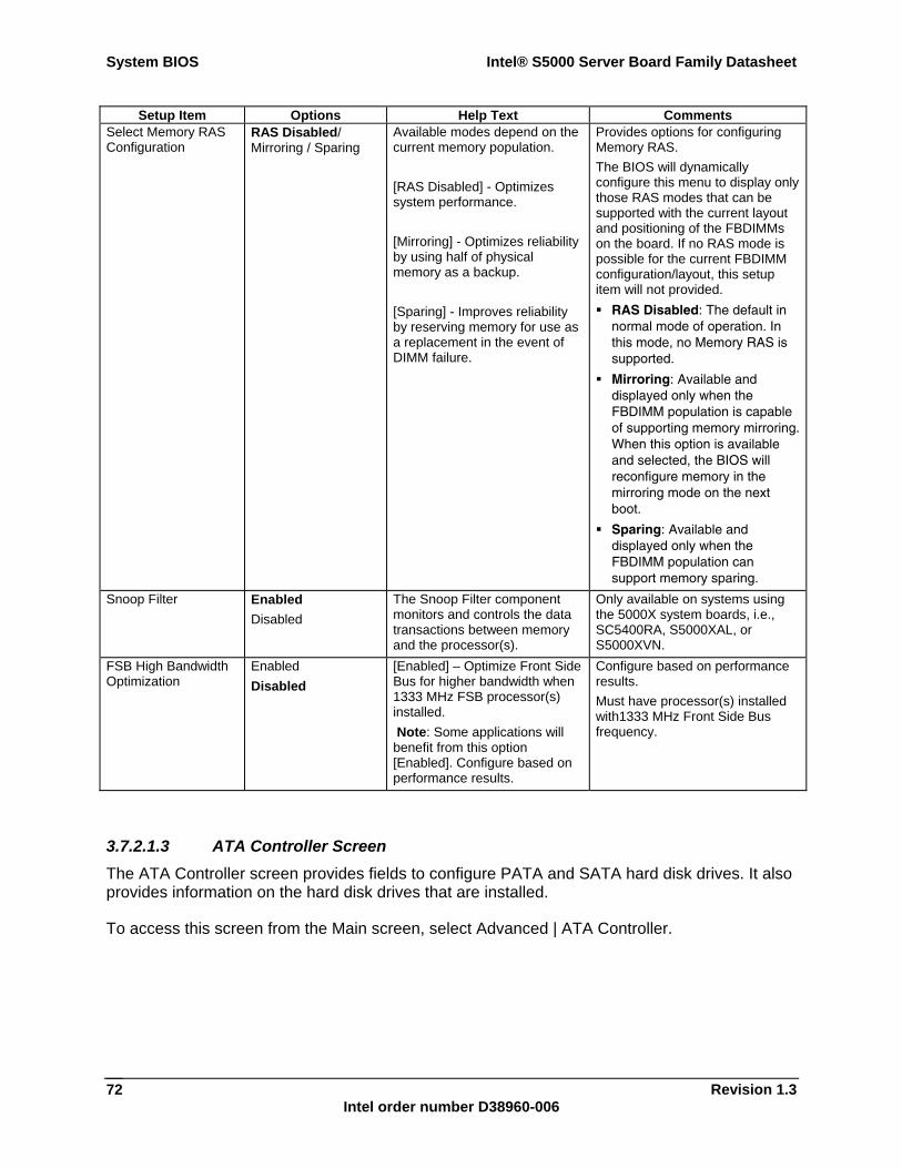
System BIOS Intel® S5000 Server Board Family Datasheet
Revision 1.3 Intel order number D38960-006
72
Setup Item Options Help Text Comments Select Memory RAS Configuration
RAS Disabled/ Mirroring / Sparing
Available modes depend on the current memory population. [RAS Disabled] - Optimizes system performance. [Mirroring] - Optimizes reliability by using half of physical memory as a backup. [Sparing] - Improves reliability by reserving memory for use as a replacement in the event of DIMM failure.
Provides options for configuring Memory RAS. The BIOS will dynamically configure this menu to display only those RAS modes that can be supported with the current layout and positioning of the FBDIMMs on the board. If no RAS mode is possible for the current FBDIMM configuration/layout, this setup item will not provided. RAS Disabled: The default in
normal mode of operation. In this mode, no Memory RAS is supported.
Mirroring: Available and displayed only when the FBDIMM population is capable of supporting memory mirroring. When this option is available and selected, the BIOS will reconfigure memory in the mirroring mode on the next boot.
Sparing: Available and displayed only when the FBDIMM population can support memory sparing.
Snoop Filter Enabled Disabled
The Snoop Filter component monitors and controls the data transactions between memory and the processor(s).
Only available on systems using the 5000X system boards, i.e., SC5400RA, S5000XAL, or S5000XVN.
FSB High Bandwidth Optimization
Enabled Disabled
[Enabled] – Optimize Front Side Bus for higher bandwidth when 1333 MHz FSB processor(s) installed. Note: Some applications will benefit from this option [Enabled]. Configure based on performance results.
Configure based on performance results. Must have processor(s) installed with1333 MHz Front Side Bus frequency.
3.7.2.1.3 ATA Controller Screen The ATA Controller screen provides fields to configure PATA and SATA hard disk drives. It also provides information on the hard disk drives that are installed.
To access this screen from the Main screen, select Advanced | ATA Controller.
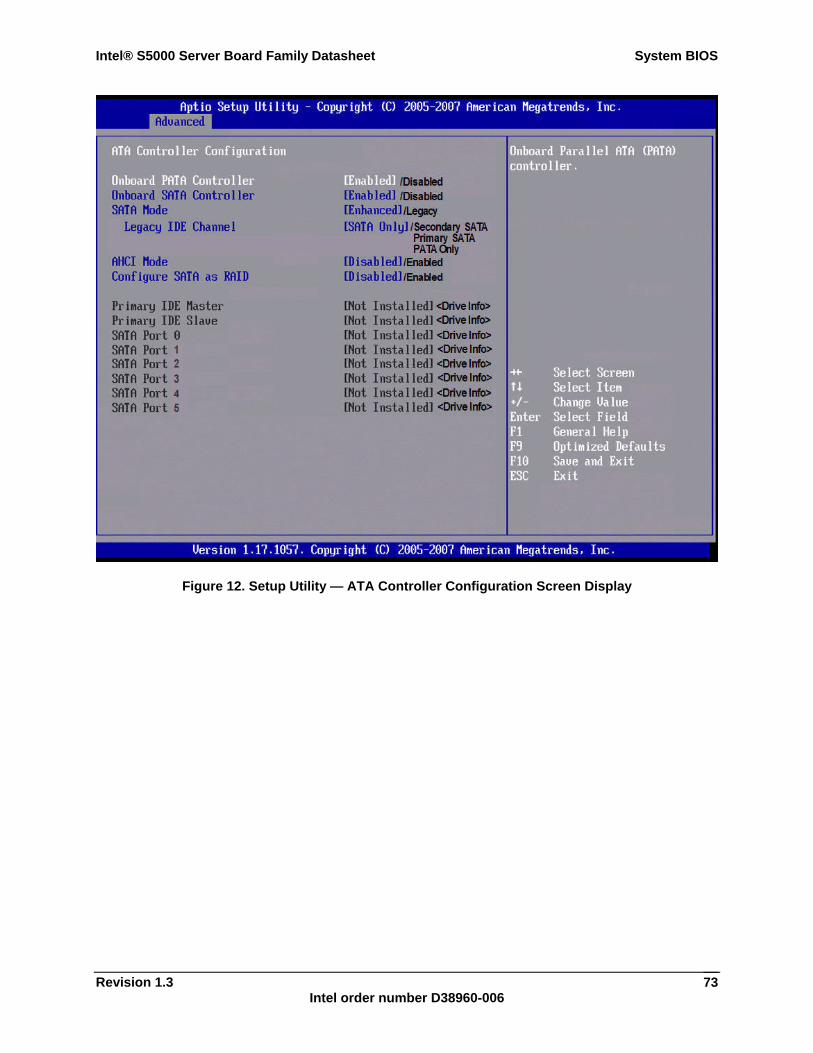
Intel® S5000 Server Board Family Datasheet System BIOS
Revision 1.3 Intel order number D38960-006
73
Figure 12. Setup Utility — ATA Controller Configuration Screen Display
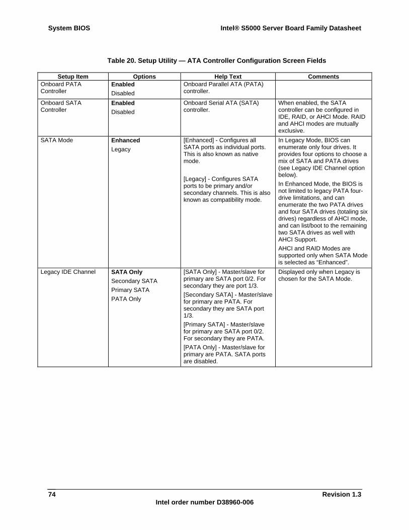
System BIOS Intel® S5000 Server Board Family Datasheet
Revision 1.3 Intel order number D38960-006
74
Table 20. Setup Utility — ATA Controller Configuration Screen Fields
Setup Item Options Help Text Comments Onboard PATA Controller
Enabled Disabled
Onboard Parallel ATA (PATA) controller.
Onboard SATA Controller
Enabled Disabled
Onboard Serial ATA (SATA) controller.
When enabled, the SATA controller can be configured in IDE, RAID, or AHCI Mode. RAID and AHCI modes are mutually exclusive.
SATA Mode Enhanced Legacy
[Enhanced] - Configures all SATA ports as individual ports. This is also known as native mode. [Legacy] - Configures SATA ports to be primary and/or secondary channels. This is also known as compatibility mode.
In Legacy Mode, BIOS can enumerate only four drives. It provides four options to choose a mix of SATA and PATA drives (see Legacy IDE Channel option below). In Enhanced Mode, the BIOS is not limited to legacy PATA four-drive limitations, and can enumerate the two PATA drives and four SATA drives (totaling six drives) regardless of AHCI mode, and can list/boot to the remaining two SATA drives as well with AHCI Support. AHCI and RAID Modes are supported only when SATA Mode is selected as “Enhanced”.
Legacy IDE Channel SATA Only Secondary SATA Primary SATA PATA Only
[SATA Only] - Master/slave for primary are SATA port 0/2. For secondary they are port 1/3. [Secondary SATA] - Master/slave for primary are PATA. For secondary they are SATA port 1/3. [Primary SATA] - Master/slave for primary are SATA port 0/2. For secondary they are PATA. [PATA Only] - Master/slave for primary are PATA. SATA ports are disabled.
Displayed only when Legacy is chosen for the SATA Mode.
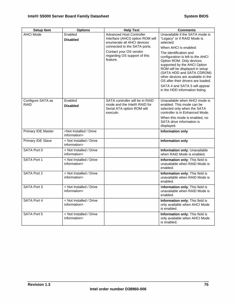
Intel® S5000 Server Board Family Datasheet System BIOS
Revision 1.3 Intel order number D38960-006
75
Setup Item Options Help Text Comments AHCI Mode Enabled
Disabled Advanced Host Controller Interface (AHCI) option ROM will enumerate all AHCI devices connected to the SATA ports. Contact your OS vendor regarding OS support of this feature.
Unavailable if the SATA mode is “Legacy” or if RAID Mode is selected. When AHCI is enabled: The identification and configuration is left to the AHCI Option ROM. Only devices supported by the AHCI Option ROM will be displayed in setup (SATA HDD and SATA CDROM) other devices are available in the OS after their drivers are loaded. SATA 4 and SATA 5 will appear in the HDD information listing.
Configure SATA as RAID
Enabled Disabled
SATA controller will be in RAID mode and the Intel® RAID for Serial ATA option ROM will execute.
Unavailable when AHCI mode is enabled. This mode can be selected only when the SATA controller is in Enhanced Mode. When this mode is enabled, no SATA drive information is displayed.
Primary IDE Master <Not Installed / Drive information>
Information only
Primary IDE Slave < Not Installed / Drive information>
Information only
SATA Port 0 < Not Installed / Drive information>
Information only; Unavailable when RAID Mode is enabled.
SATA Port 1 < Not Installed / Drive information>
Information only; This field is unavailable when RAID Mode is enabled.
SATA Port 2 < Not Installed / Drive information>
Information only; This field is unavailable when RAID Mode is enabled.
SATA Port 3 < Not Installed / Drive information>
Information only; This field is unavailable when RAID Mode is enabled.
SATA Port 4 < Not Installed / Drive information>
Information only; This field is only available when AHCI Mode is enabled.
SATA Port 5 < Not Installed / Drive information>
Information only; This field is only available when AHCI Mode is enabled.
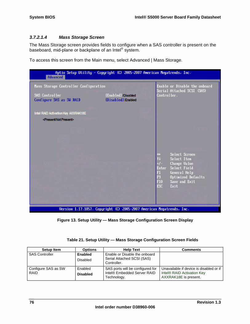
System BIOS Intel® S5000 Server Board Family Datasheet
Revision 1.3 Intel order number D38960-006
76
3.7.2.1.4 Mass Storage Screen The Mass Storage screen provides fields to configure when a SAS controller is present on the baseboard, mid-plane or backplane of an Intel® system.
To access this screen from the Main menu, select Advanced | Mass Storage.
Figure 13. Setup Utility — Mass Storage Configuration Screen Display
Table 21. Setup Utility — Mass Storage Configuration Screen Fields
Setup Item Options Help Text Comments SAS Controller Enabled
Disabled Enable or Disable the onboard Serial Attached SCSI (SAS) Controller.
Configure SAS as SW RAID
Enabled Disabled
SAS ports will be configured for Intel® Embedded Server RAID Technology.
Unavailable if device is disabled or if Intel® RAID Activation Key AXXRAK18E is present.
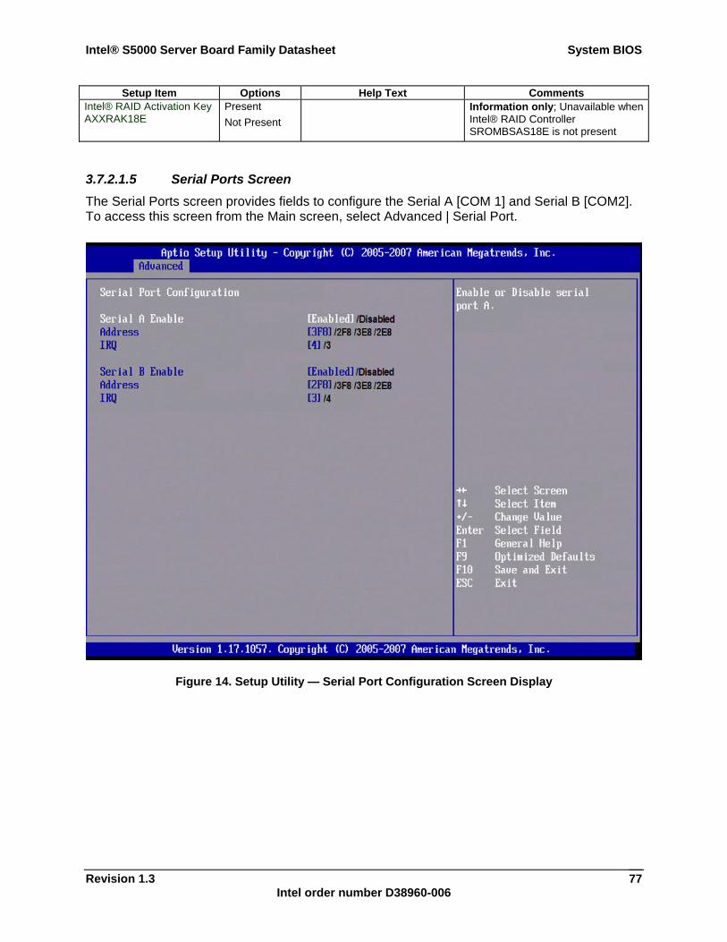
Intel® S5000 Server Board Family Datasheet System BIOS
Revision 1.3 Intel order number D38960-006
77
Setup Item Options Help Text Comments Intel® RAID Activation Key AXXRAK18E
Present Not Present
Information only; Unavailable when Intel® RAID Controller SROMBSAS18E is not present
3.7.2.1.5 Serial Ports Screen The Serial Ports screen provides fields to configure the Serial A [COM 1] and Serial B [COM2]. To access this screen from the Main screen, select Advanced | Serial Port.
Figure 14. Setup Utility — Serial Port Configuration Screen Display
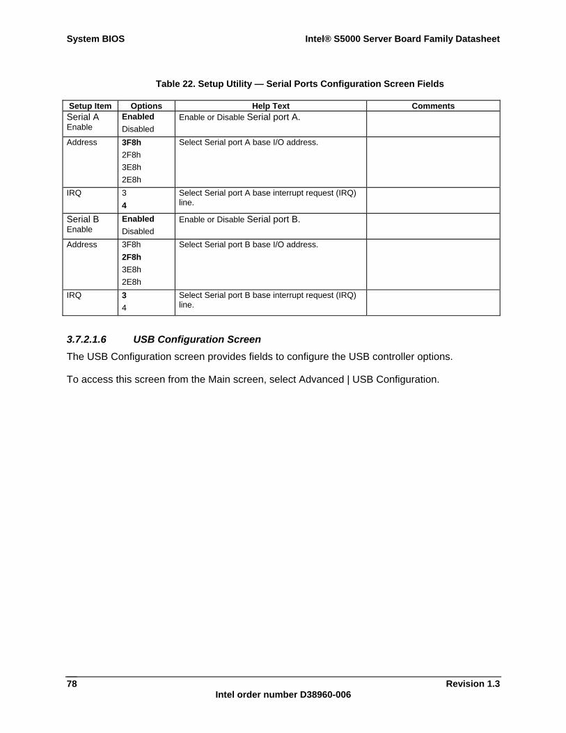
System BIOS Intel® S5000 Server Board Family Datasheet
Revision 1.3 Intel order number D38960-006
78
Table 22. Setup Utility — Serial Ports Configuration Screen Fields
Setup Item Options Help Text Comments Serial A Enable
Enabled Disabled
Enable or Disable Serial port A.
Address 3F8h 2F8h 3E8h 2E8h
Select Serial port A base I/O address.
IRQ 3 4
Select Serial port A base interrupt request (IRQ) line.
Serial B Enable
Enabled Disabled
Enable or Disable Serial port B.
Address 3F8h 2F8h 3E8h 2E8h
Select Serial port B base I/O address.
IRQ 3 4
Select Serial port B base interrupt request (IRQ) line.
3.7.2.1.6 USB Configuration Screen The USB Configuration screen provides fields to configure the USB controller options.
To access this screen from the Main screen, select Advanced | USB Configuration.
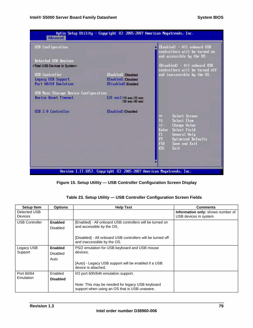
Intel® S5000 Server Board Family Datasheet System BIOS
Revision 1.3 Intel order number D38960-006
79
Figure 15. Setup Utility — USB Controller Configuration Screen Display
Table 23. Setup Utility — USB Controller Configuration Screen Fields
Setup Item Options Help Text Comments Detected USB Devices
Information only: shows number of USB devices in system
USB Controller Enabled Disabled
[Enabled] - All onboard USB controllers will be turned on and accessible by the OS. [Disabled] - All onboard USB controllers will be turned off and inaccessible by the OS.
Legacy USB Support
Enabled Disabled Auto
PS/2 emulation for USB keyboard and USB mouse devices. [Auto] - Legacy USB support will be enabled if a USB device is attached.
Port 60/64 Emulation
Enabled Disabled
I/O port 60h/64h emulation support. Note: This may be needed for legacy USB keyboard support when using an OS that is USB unaware.
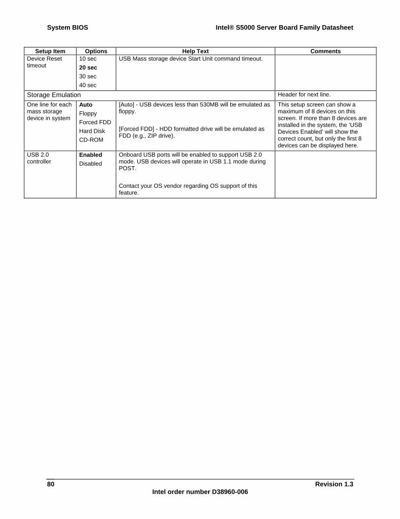
System BIOS Intel® S5000 Server Board Family Datasheet
Revision 1.3 Intel order number D38960-006
80
Setup Item Options Help Text Comments Device Reset timeout
10 sec 20 sec 30 sec 40 sec
USB Mass storage device Start Unit command timeout.
Storage Emulation Header for next line.
One line for each mass storage device in system
Auto Floppy Forced FDD Hard Disk CD-ROM
[Auto] - USB devices less than 530MB will be emulated as floppy. [Forced FDD] - HDD formatted drive will be emulated as FDD (e.g., ZIP drive).
This setup screen can show a maximum of 8 devices on this screen. If more than 8 devices are installed in the system, the ‘USB Devices Enabled’ will show the correct count, but only the first 8 devices can be displayed here.
USB 2.0 controller
Enabled Disabled
Onboard USB ports will be enabled to support USB 2.0 mode. USB devices will operate in USB 1.1 mode during POST. Contact your OS vendor regarding OS support of this feature.
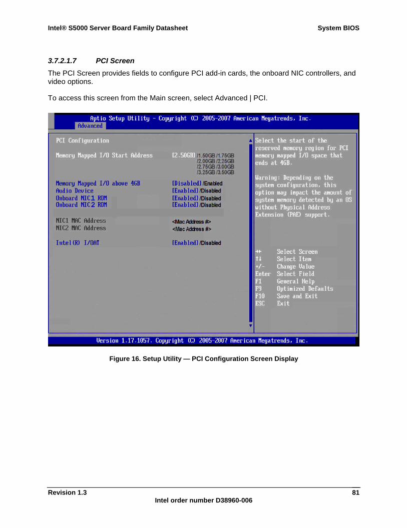
Intel® S5000 Server Board Family Datasheet System BIOS
Revision 1.3 Intel order number D38960-006
81
3.7.2.1.7 PCI Screen The PCI Screen provides fields to configure PCI add-in cards, the onboard NIC controllers, and video options.
To access this screen from the Main screen, select Advanced | PCI.
Figure 16. Setup Utility — PCI Configuration Screen Display
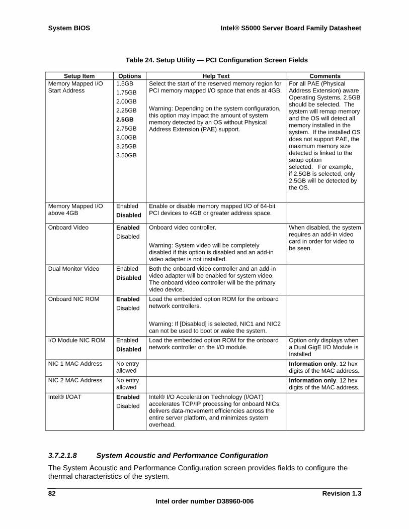
System BIOS Intel® S5000 Server Board Family Datasheet
Revision 1.3 Intel order number D38960-006
82
Table 24. Setup Utility — PCI Configuration Screen Fields
Setup Item Options Help Text Comments Memory Mapped I/O Start Address
1.5GB 1.75GB 2.00GB 2.25GB 2.5GB 2.75GB 3.00GB 3.25GB 3.50GB
Select the start of the reserved memory region for PCI memory mapped I/O space that ends at 4GB. Warning: Depending on the system configuration, this option may impact the amount of system memory detected by an OS without Physical Address Extension (PAE) support.
For all PAE (Physical Address Extension) aware Operating Systems, 2.5GB should be selected. The system will remap memory and the OS will detect all memory installed in the system. If the installed OS does not support PAE, the maximum memory size detected is linked to the setup option selected. For example, if 2.5GB is selected, only 2.5GB will be detected by the OS.
Memory Mapped I/O above 4GB
Enabled Disabled
Enable or disable memory mapped I/O of 64-bit PCI devices to 4GB or greater address space.
Onboard Video Enabled Disabled
Onboard video controller. Warning: System video will be completely disabled if this option is disabled and an add-in video adapter is not installed.
When disabled, the system requires an add-in video card in order for video to be seen.
Dual Monitor Video Enabled Disabled
Both the onboard video controller and an add-in video adapter will be enabled for system video. The onboard video controller will be the primary video device.
Onboard NIC ROM Enabled Disabled
Load the embedded option ROM for the onboard network controllers. Warning: If [Disabled] is selected, NIC1 and NIC2 can not be used to boot or wake the system.
I/O Module NIC ROM Enabled Disabled
Load the embedded option ROM for the onboard network controller on the I/O module.
Option only displays when a Dual GigE I/O Module is Installed
NIC 1 MAC Address No entry allowed
Information only. 12 hex digits of the MAC address.
NIC 2 MAC Address No entry allowed
Information only. 12 hex digits of the MAC address.
Intel® I/OAT Enabled Disabled
Intel® I/O Acceleration Technology (I/OAT) accelerates TCP/IP processing for onboard NICs, delivers data-movement efficiencies across the entire server platform, and minimizes system overhead.
3.7.2.1.8 System Acoustic and Performance Configuration The System Acoustic and Performance Configuration screen provides fields to configure the thermal characteristics of the system.
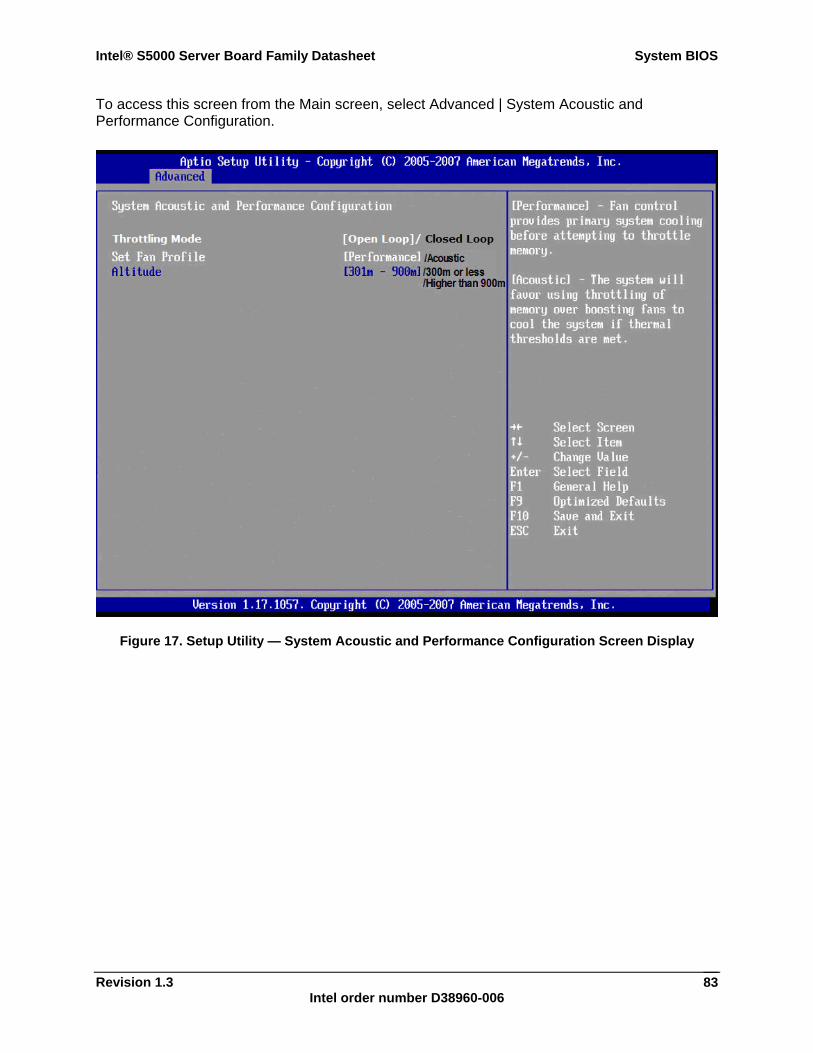
Intel® S5000 Server Board Family Datasheet System BIOS
Revision 1.3 Intel order number D38960-006
83
To access this screen from the Main screen, select Advanced | System Acoustic and Performance Configuration.
Figure 17. Setup Utility — System Acoustic and Performance Configuration Screen Display
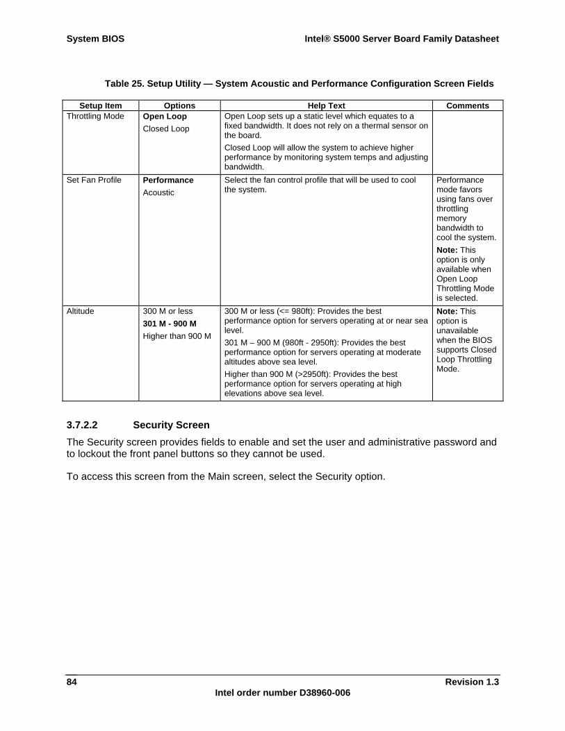
System BIOS Intel® S5000 Server Board Family Datasheet
Revision 1.3 Intel order number D38960-006
84
Table 25. Setup Utility — System Acoustic and Performance Configuration Screen Fields
Setup Item Options Help Text Comments Throttling Mode Open Loop
Closed Loop Open Loop sets up a static level which equates to a fixed bandwidth. It does not rely on a thermal sensor on the board. Closed Loop will allow the system to achieve higher performance by monitoring system temps and adjusting bandwidth.
Set Fan Profile Performance Acoustic
Select the fan control profile that will be used to cool the system.
Performance mode favors using fans over throttling memory bandwidth to cool the system. Note: This option is only available when Open Loop Throttling Mode is selected.
Altitude 300 M or less 301 M - 900 M Higher than 900 M
300 M or less (<= 980ft): Provides the best performance option for servers operating at or near sea level. 301 M – 900 M (980ft - 2950ft): Provides the best performance option for servers operating at moderate altitudes above sea level. Higher than 900 M (>2950ft): Provides the best performance option for servers operating at high elevations above sea level.
Note: This option is unavailable when the BIOS supports Closed Loop Throttling Mode.
3.7.2.2 Security Screen The Security screen provides fields to enable and set the user and administrative password and to lockout the front panel buttons so they cannot be used.
To access this screen from the Main screen, select the Security option.
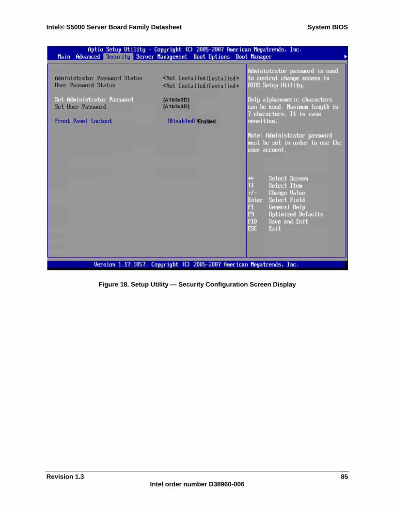
Intel® S5000 Server Board Family Datasheet System BIOS
Revision 1.3 Intel order number D38960-006
85
Figure 18. Setup Utility — Security Configuration Screen Display
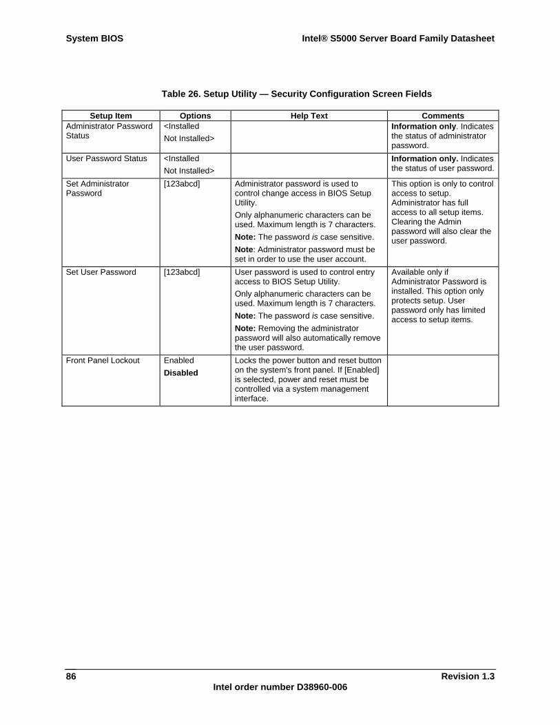
System BIOS Intel® S5000 Server Board Family Datasheet
Revision 1.3 Intel order number D38960-006
86
Table 26. Setup Utility — Security Configuration Screen Fields
Setup Item Options Help Text Comments Administrator Password Status
<Installed Not Installed>
Information only. Indicates the status of administrator password.
User Password Status <Installed Not Installed>
Information only. Indicates the status of user password.
Set Administrator Password
[123abcd] Administrator password is used to control change access in BIOS Setup Utility. Only alphanumeric characters can be used. Maximum length is 7 characters. Note: The password is case sensitive. Note: Administrator password must be set in order to use the user account.
This option is only to control access to setup. Administrator has full access to all setup items. Clearing the Admin password will also clear the user password.
Set User Password [123abcd] User password is used to control entry access to BIOS Setup Utility. Only alphanumeric characters can be used. Maximum length is 7 characters. Note: The password is case sensitive. Note: Removing the administrator password will also automatically remove the user password.
Available only if Administrator Password is installed. This option only protects setup. User password only has limited access to setup items.
Front Panel Lockout Enabled Disabled
Locks the power button and reset button on the system's front panel. If [Enabled] is selected, power and reset must be controlled via a system management interface.
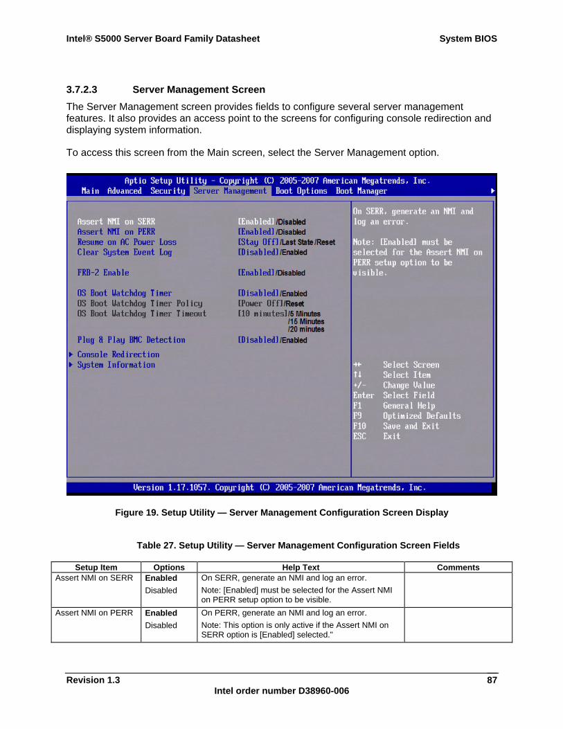
Intel® S5000 Server Board Family Datasheet System BIOS
Revision 1.3 Intel order number D38960-006
87
3.7.2.3 Server Management Screen The Server Management screen provides fields to configure several server management features. It also provides an access point to the screens for configuring console redirection and displaying system information.
To access this screen from the Main screen, select the Server Management option.
Figure 19. Setup Utility — Server Management Configuration Screen Display
Table 27. Setup Utility — Server Management Configuration Screen Fields
Setup Item Options Help Text Comments Assert NMI on SERR Enabled
Disabled On SERR, generate an NMI and log an error. Note: [Enabled] must be selected for the Assert NMI on PERR setup option to be visible.
Assert NMI on PERR Enabled Disabled
On PERR, generate an NMI and log an error. Note: This option is only active if the Assert NMI on SERR option is [Enabled] selected."
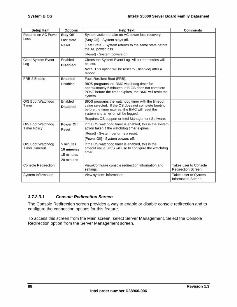
System BIOS Intel® S5000 Server Board Family Datasheet
Revision 1.3 Intel order number D38960-006
88
Setup Item Options Help Text Comments Resume on AC Power Loss
Stay Off Last state Reset
System action to take on AC power loss recovery. [Stay Off] - System stays off. [Last State] - System returns to the same state before the AC power loss. [Reset] - System powers on.
Clear System Event Log
Enabled Disabled
Clears the System Event Log. All current entries will be lost. Note: This option will be reset to [Disabled] after a reboot.
FRB-2 Enable Enabled Disabled
Fault Resilient Boot (FRB). BIOS programs the BMC watchdog timer for approximately 6 minutes. If BIOS does not complete POST before the timer expires, the BMC will reset the system.
O/S Boot Watchdog Timer
Enabled Disabled
BIOS programs the watchdog timer with the timeout value selected. If the OS does not complete booting before the timer expires, the BMC will reset the system and an error will be logged. Requires OS support or Intel Management Software.
O/S Boot Watchdog Timer Policy
Power Off Reset
If the OS watchdog timer is enabled, this is the system action taken if the watchdog timer expires. [Reset] - System performs a reset. [Power Off] - System powers off.
O/S Boot Watchdog Timer Timeout
5 minutes 10 minutes 15 minutes 20 minutes
If the OS watchdog timer is enabled, this is the timeout value BIOS will use to configure the watchdog timer.
Console Redirection View/Configure console redirection information and settings.
Takes user to Console Redirection Screen.
System Information View system information Takes user to System Information Screen.
3.7.2.3.1 Console Redirection Screen The Console Redirection screen provides a way to enable or disable console redirection and to configure the connection options for this feature.
To access this screen from the Main screen, select Server Management. Select the Console Redirection option from the Server Management screen.
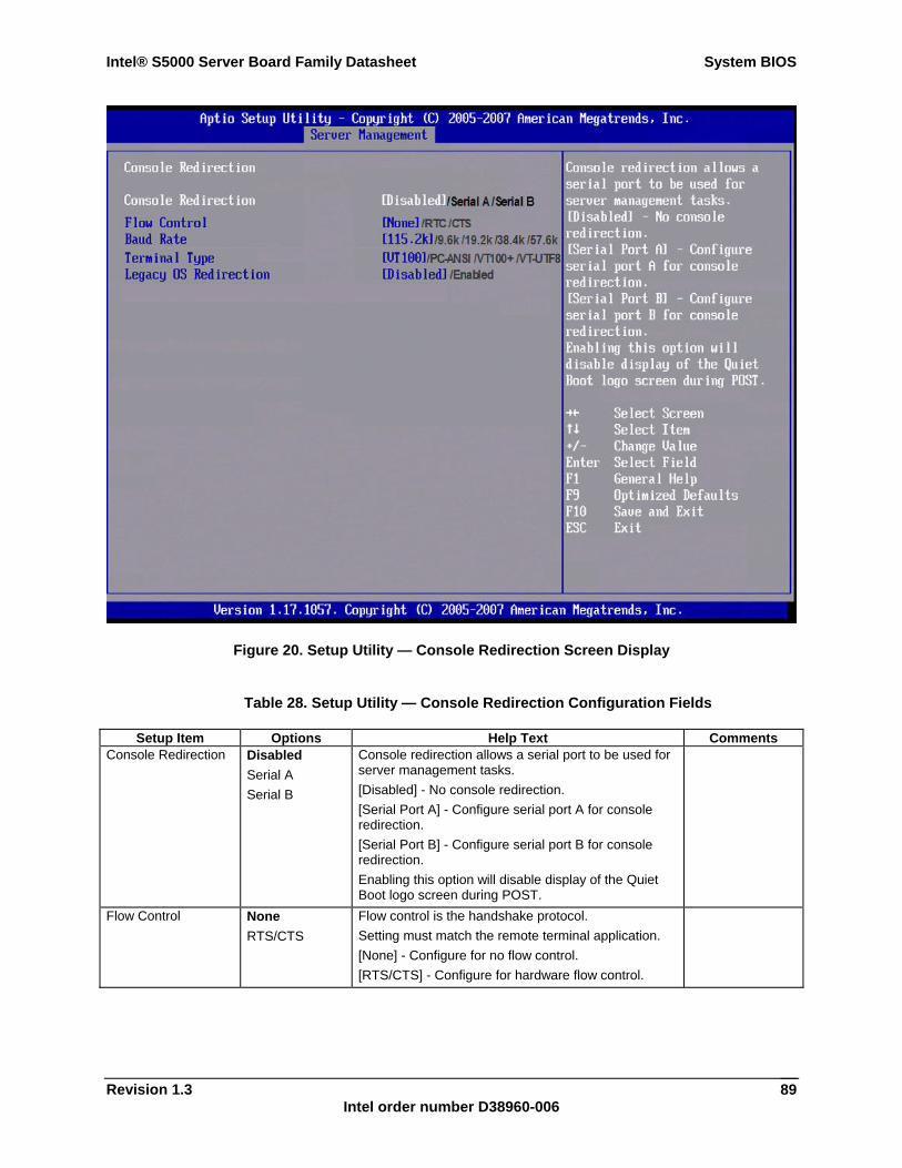
Intel® S5000 Server Board Family Datasheet System BIOS
Revision 1.3 Intel order number D38960-006
89
Figure 20. Setup Utility — Console Redirection Screen Display
Table 28. Setup Utility — Console Redirection Configuration Fields
Setup Item Options Help Text Comments Console Redirection Disabled
Serial A Serial B
Console redirection allows a serial port to be used for server management tasks. [Disabled] - No console redirection. [Serial Port A] - Configure serial port A for console redirection. [Serial Port B] - Configure serial port B for console redirection. Enabling this option will disable display of the Quiet Boot logo screen during POST.
Flow Control None RTS/CTS
Flow control is the handshake protocol. Setting must match the remote terminal application. [None] - Configure for no flow control. [RTS/CTS] - Configure for hardware flow control.
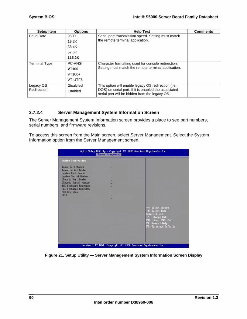
System BIOS Intel® S5000 Server Board Family Datasheet
Revision 1.3 Intel order number D38960-006
90
Setup Item Options Help Text Comments Baud Rate 9600
19.2K 38.4K 57.6K 115.2K
Serial port transmission speed. Setting must match the remote terminal application.
Terminal Type PC-ANSI VT100 VT100+ VT-UTF8
Character formatting used for console redirection. Setting must match the remote terminal application.
Legacy OS Redirection
Disabled Enabled
This option will enable legacy OS redirection (i.e., DOS) on serial port. If it is enabled the associated serial port will be hidden from the legacy OS.
3.7.2.4 Server Management System Information Screen The Server Management System Information screen provides a place to see part numbers, serial numbers, and firmware revisions.
To access this screen from the Main screen, select Server Management. Select the System Information option from the Server Management screen.
Figure 21. Setup Utility — Server Management System Information Screen Display
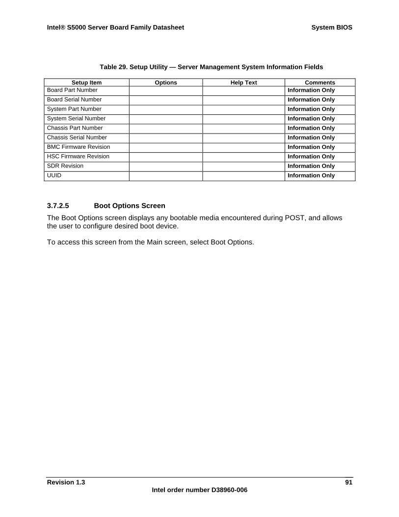
Intel® S5000 Server Board Family Datasheet System BIOS
Revision 1.3 Intel order number D38960-006
91
Table 29. Setup Utility — Server Management System Information Fields
Setup Item Options Help Text Comments Board Part Number Information Only Board Serial Number Information Only System Part Number Information Only System Serial Number Information Only Chassis Part Number Information Only Chassis Serial Number Information Only BMC Firmware Revision Information Only HSC Firmware Revision Information Only SDR Revision Information Only UUID Information Only
3.7.2.5 Boot Options Screen The Boot Options screen displays any bootable media encountered during POST, and allows the user to configure desired boot device.
To access this screen from the Main screen, select Boot Options.
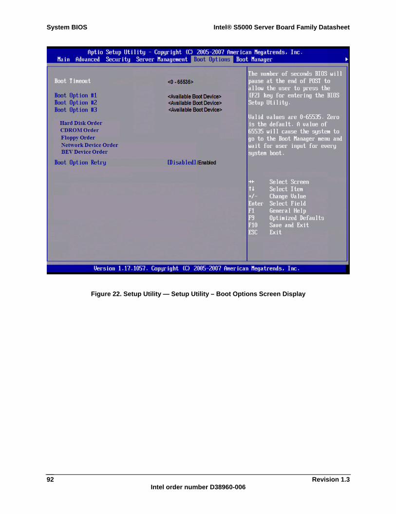
System BIOS Intel® S5000 Server Board Family Datasheet
Revision 1.3 Intel order number D38960-006
92
Figure 22. Setup Utility — Setup Utility – Boot Options Screen Display
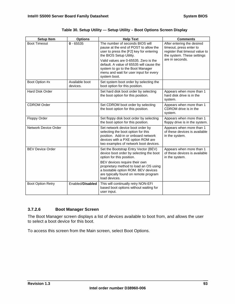
Intel® S5000 Server Board Family Datasheet System BIOS
Revision 1.3 Intel order number D38960-006
93
Table 30. Setup Utility — Setup Utility – Boot Options Screen Display
Setup Item Options Help Text Comments Boot Timeout 0 - 65535 The number of seconds BIOS will
pause at the end of POST to allow the user to press the [F2] key for entering the BIOS Setup Utility. Valid values are 0-65535. Zero is the default. A value of 65535 will cause the system to go to the Boot Manager menu and wait for user input for every system boot.
After entering the desired timeout, press enter to register that timeout value to the system. These settings are in seconds.
Boot Option #x Available boot devices.
Set system boot order by selecting the boot option for this position.
Hard Disk Order Set hard disk boot order by selecting the boot option for this position.
Appears when more than 1 hard disk drive is in the system.
CDROM Order Set CDROM boot order by selecting the boot option for this position.
Appears when more than 1 CDROM drive is in the system.
Floppy Order Set floppy disk boot order by selecting the boot option for this position.
Appears when more than 1 floppy drive is in the system.
Network Device Order Set network device boot order by selecting the boot option for this position. Add-in or onboard network devices with a PXE option ROM are two examples of network boot devices.
Appears when more than 1 of these devices is available in the system.
BEV Device Order Set the Bootstrap Entry Vector (BEV) device boot order by selecting the boot option for this position. BEV devices require their own proprietary method to load an OS using a bootable option ROM. BEV devices are typically found on remote program load devices.
Appears when more than 1 of these devices is available in the system.
Boot Option Retry Enabled/Disabled This will continually retry NON-EFI based boot options without waiting for user input.
3.7.2.6 Boot Manager Screen The Boot Manager screen displays a list of devices available to boot from, and allows the user to select a boot device for this boot.
To access this screen from the Main screen, select Boot Options.
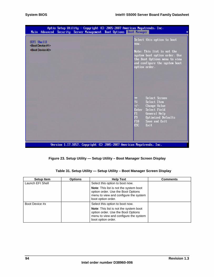
System BIOS Intel® S5000 Server Board Family Datasheet
Revision 1.3 Intel order number D38960-006
94
Figure 23. Setup Utility — Setup Utility – Boot Manager Screen Display
Table 31. Setup Utility — Setup Utility – Boot Manager Screen Display
Setup Item Options Help Text Comments Launch EFI Shell Select this option to boot now.
Note: This list is not the system boot option order. Use the Boot Options menu to view and configure the system boot option order.
Boot Device #x Select this option to boot now. Note: This list is not the system boot option order. Use the Boot Options menu to view and configure the system boot option order.
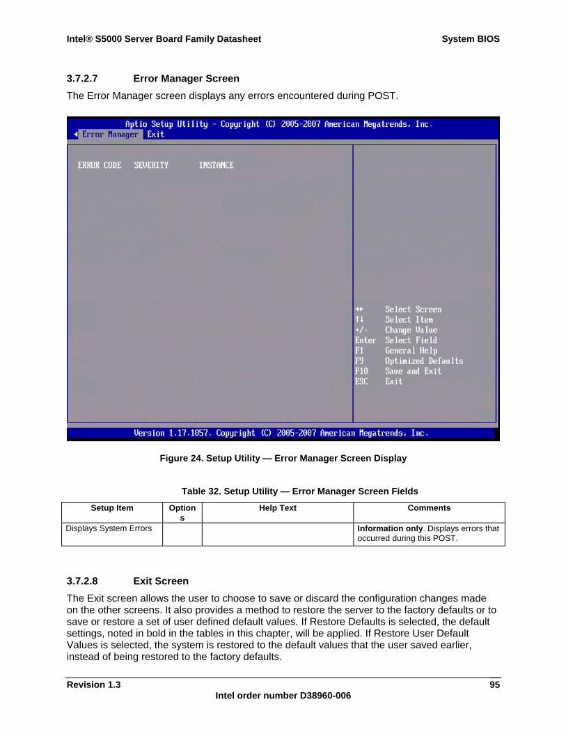
Intel® S5000 Server Board Family Datasheet System BIOS
Revision 1.3 Intel order number D38960-006
95
3.7.2.7 Error Manager Screen The Error Manager screen displays any errors encountered during POST.
Figure 24. Setup Utility — Error Manager Screen Display
Table 32. Setup Utility — Error Manager Screen Fields
Setup Item Options
Help Text Comments
Displays System Errors Information only. Displays errors that occurred during this POST.
3.7.2.8 Exit Screen The Exit screen allows the user to choose to save or discard the configuration changes made on the other screens. It also provides a method to restore the server to the factory defaults or to save or restore a set of user defined default values. If Restore Defaults is selected, the default settings, noted in bold in the tables in this chapter, will be applied. If Restore User Default Values is selected, the system is restored to the default values that the user saved earlier, instead of being restored to the factory defaults.
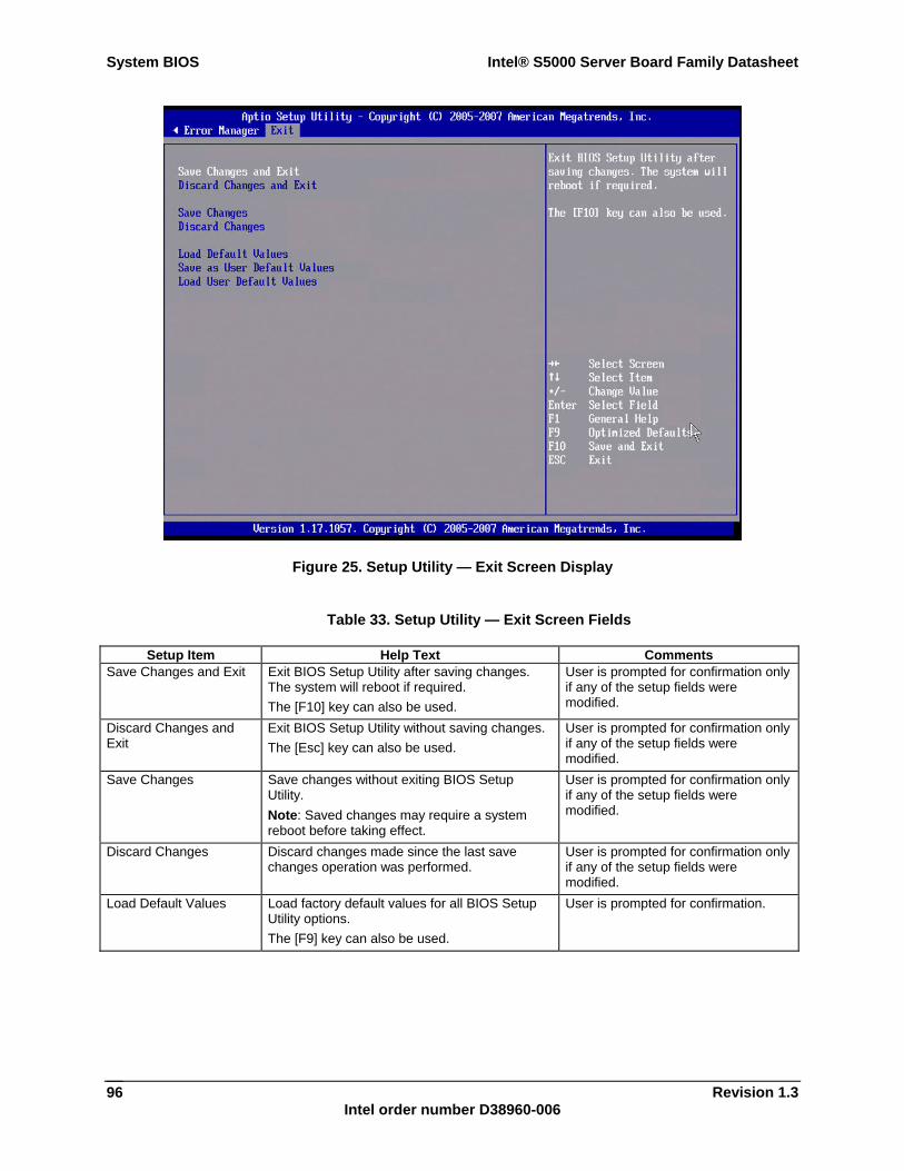
System BIOS Intel® S5000 Server Board Family Datasheet
Revision 1.3 Intel order number D38960-006
96
Figure 25. Setup Utility — Exit Screen Display
Table 33. Setup Utility — Exit Screen Fields
Setup Item Help Text Comments Save Changes and Exit Exit BIOS Setup Utility after saving changes.
The system will reboot if required. The [F10] key can also be used.
User is prompted for confirmation only if any of the setup fields were modified.
Discard Changes and Exit
Exit BIOS Setup Utility without saving changes. The [Esc] key can also be used.
User is prompted for confirmation only if any of the setup fields were modified.
Save Changes Save changes without exiting BIOS Setup Utility. Note: Saved changes may require a system reboot before taking effect.
User is prompted for confirmation only if any of the setup fields were modified.
Discard Changes Discard changes made since the last save changes operation was performed.
User is prompted for confirmation only if any of the setup fields were modified.
Load Default Values Load factory default values for all BIOS Setup Utility options. The [F9] key can also be used.
User is prompted for confirmation.
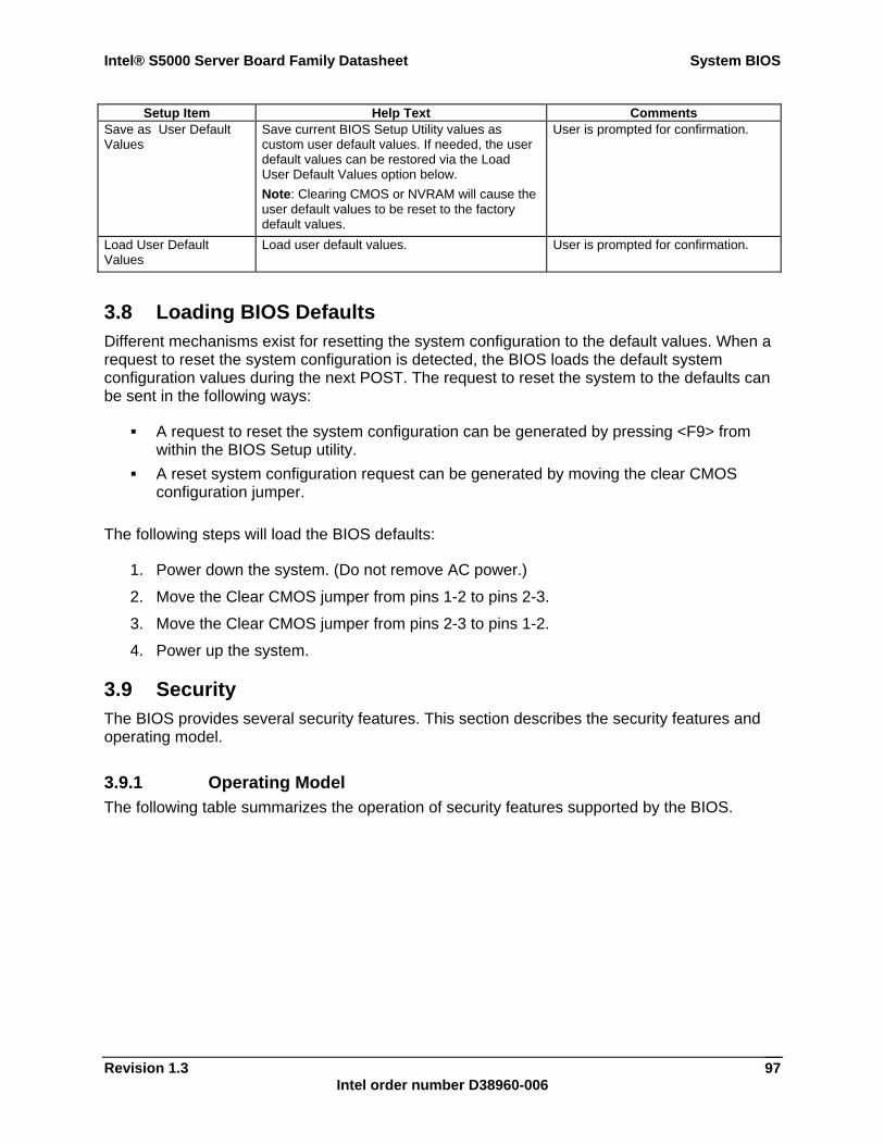
Intel® S5000 Server Board Family Datasheet System BIOS
Revision 1.3 Intel order number D38960-006
97
Setup Item Help Text Comments Save as User Default Values
Save current BIOS Setup Utility values as custom user default values. If needed, the user default values can be restored via the Load User Default Values option below. Note: Clearing CMOS or NVRAM will cause the user default values to be reset to the factory default values.
User is prompted for confirmation.
Load User Default Values
Load user default values. User is prompted for confirmation.
3.8 Loading BIOS Defaults Different mechanisms exist for resetting the system configuration to the default values. When a request to reset the system configuration is detected, the BIOS loads the default system configuration values during the next POST. The request to reset the system to the defaults can be sent in the following ways:
A request to reset the system configuration can be generated by pressing <F9> from within the BIOS Setup utility.
A reset system configuration request can be generated by moving the clear CMOS configuration jumper.
The following steps will load the BIOS defaults:
1. Power down the system. (Do not remove AC power.)
2. Move the Clear CMOS jumper from pins 1-2 to pins 2-3.
3. Move the Clear CMOS jumper from pins 2-3 to pins 1-2.
4. Power up the system.
3.9 Security The BIOS provides several security features. This section describes the security features and operating model.
3.9.1 Operating Model The following table summarizes the operation of security features supported by the BIOS.
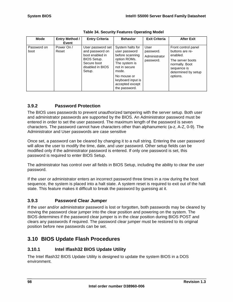
System BIOS Intel® S5000 Server Board Family Datasheet
Revision 1.3 Intel order number D38960-006
98
Table 34. Security Features Operating Model
Mode Entry Method / Event
Entry Criteria Behavior Exit Criteria After Exit
Password on boot
Power On / Reset
User password set and password on boot enabled in BIOS Setup. Secure boot disabled in BIOS Setup.
System halts for user password before scanning option ROMs. The system is not in secure mode. No mouse or keyboard input is accepted except the password.
User password. Administrator password.
Front control panel buttons are re-enabled. The server boots normally. Boot sequence is determined by setup options.
3.9.2 Password Protection The BIOS uses passwords to prevent unauthorized tampering with the server setup. Both user and administrator passwords are supported by the BIOS. An Administrator password must be entered in order to set the user password. The maximum length of the password is seven characters. The password cannot have characters other than alphanumeric (a-z, A-Z, 0-9). The Administrator and User passwords are case sensitive
Once set, a password can be cleared by changing it to a null string. Entering the user password will allow the user to modify the time, date, and user password. Other setup fields can be modified only if the administrator password is entered. If only one password is set, this password is required to enter BIOS Setup.
The administrator has control over all fields in BIOS Setup, including the ability to clear the user password.
If the user or administrator enters an incorrect password three times in a row during the boot sequence, the system is placed into a halt state. A system reset is required to exit out of the halt state. This feature makes it difficult to break the password by guessing at it.
3.9.3 Password Clear Jumper If the user and/or administrator password is lost or forgotten, both passwords may be cleared by moving the password clear jumper into the clear position and powering on the system. The BIOS determines if the password clear jumper is in the clear position during BIOS POST and clears any passwords if required. The password clear jumper must be restored to its original position before new passwords can be set.
3.10 BIOS Update Flash Procedures
3.10.1 Intel Iflash32 BIOS Update Utility The Intel Iflash32 BIOS Update Utility is designed to update the system BIOS in a DOS environment.
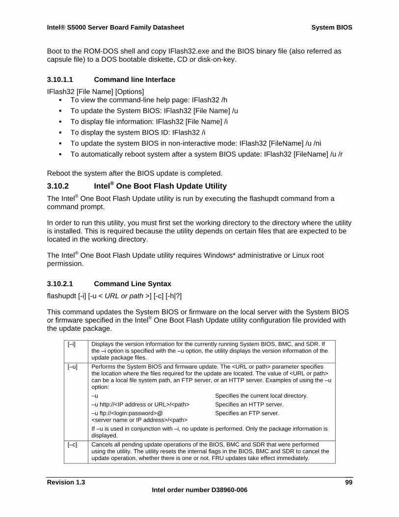
Intel® S5000 Server Board Family Datasheet System BIOS
Revision 1.3 Intel order number D38960-006
99
Boot to the ROM-DOS shell and copy IFlash32.exe and the BIOS binary file (also referred as capsule file) to a DOS bootable diskette, CD or disk-on-key.
3.10.1.1 Command line Interface IFlash32 [File Name] [Options]
To view the command-line help page: IFlash32 /h To update the System BIOS: IFlash32 [File Name] /u To display file information: IFlash32 [File Name] /i To display the system BIOS ID: IFlash32 /i To update the system BIOS in non-interactive mode: IFlash32 [FileName] /u /ni To automatically reboot system after a system BIOS update: IFlash32 [FileName] /u /r
Reboot the system after the BIOS update is completed.
3.10.2 Intel® One Boot Flash Update Utility The Intel® One Boot Flash Update utility is run by executing the flashupdt command from a command prompt.
In order to run this utility, you must first set the working directory to the directory where the utility is installed. This is required because the utility depends on certain files that are expected to be located in the working directory.
The Intel® One Boot Flash Update utility requires Windows* administrative or Linux root permission.
3.10.2.1 Command Line Syntax flashupdt [-i] [-u < URL or path >] [-c] [-h|?]
This command updates the System BIOS or firmware on the local server with the System BIOS or firmware specified in the Intel® One Boot Flash Update utility configuration file provided with the update package.
[–i] Displays the version information for the currently running System BIOS, BMC, and SDR. If the –i option is specified with the –u option, the utility displays the version information of the update package files.
[–u] Performs the System BIOS and firmware update. The <URL or path> parameter specifies the location where the files required for the update are located. The value of <URL or path> can be a local file system path, an FTP server, or an HTTP server. Examples of using the –u option:
–u –u http://<IP address or URL>/<path> –u ftp://<login:password>@ <server name or IP address>/<path>
Specifies the current local directory. Specifies an HTTP server. Specifies an FTP server.
If –u is used in conjunction with –i, no update is performed. Only the package information is displayed.
[–c] Cancels all pending update operations of the BIOS, BMC and SDR that were performed using the utility. The utility resets the internal flags in the BIOS, BMC and SDR to cancel the update operation, whether there is one or not. FRU updates take effect immediately.
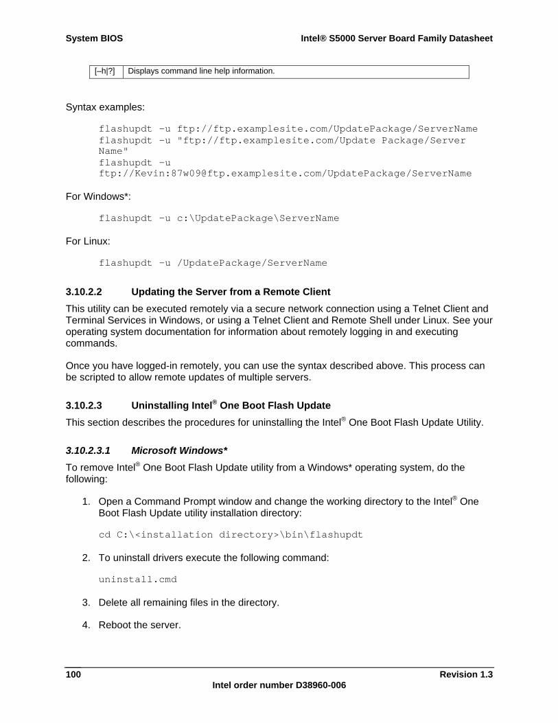
System BIOS Intel® S5000 Server Board Family Datasheet
Revision 1.3 Intel order number D38960-006
100
[–h|?] Displays command line help information.
Syntax examples:
flashupdt –u ftp://ftp.examplesite.com/UpdatePackage/ServerName flashupdt –u "ftp://ftp.examplesite.com/Update Package/Server Name" flashupdt –u ftp://Kevin:[email protected]/UpdatePackage/ServerName
For Windows*:
flashupdt –u c:\UpdatePackage\ServerName
For Linux:
flashupdt –u /UpdatePackage/ServerName
3.10.2.2 Updating the Server from a Remote Client This utility can be executed remotely via a secure network connection using a Telnet Client and Terminal Services in Windows, or using a Telnet Client and Remote Shell under Linux. See your operating system documentation for information about remotely logging in and executing commands.
Once you have logged-in remotely, you can use the syntax described above. This process can be scripted to allow remote updates of multiple servers.
3.10.2.3 Uninstalling Intel® One Boot Flash Update This section describes the procedures for uninstalling the Intel® One Boot Flash Update Utility.
3.10.2.3.1 Microsoft Windows* To remove Intel® One Boot Flash Update utility from a Windows* operating system, do the following:
1. Open a Command Prompt window and change the working directory to the Intel® One Boot Flash Update utility installation directory:
cd C:\<installation directory>\bin\flashupdt
2. To uninstall drivers execute the following command:
uninstall.cmd
3. Delete all remaining files in the directory.
4. Reboot the server.
Intel® S5000 Server Board Family Datasheet System BIOS
Revision 1.3 Intel order number D38960-006
101
3.10.2.3.2 Linux To remove the Intel® One Boot Flash Update utility from a Linux operating system, do the following:
1. Log in as root.
2. Open a terminal and change the working directory to the Intel® One Boot Flash Update utility installation directory:
cd /usr/local/flashupdt
3. Execute the following command:
/uninstall
3.11 BIOS Bank Select and One Boot Flash Update One Boot Flash Update refers to the ability to update the BIOS while the server is online and operating.
The BIOS Bank Select feature provides the ability to update the BIOS in a fault tolerant way. If the updated (new) BIOS is found to be non functional for any reason, the system can still be booted by rolling back to the previous, healthy BIOS.
All Intel® server boards and systems that use the Intel® 5000 Chipset Sequence have 4 MB of flash space for system BIOS. This flash is divided into 2 banks of 2 MB each. One of the banks is called upper bank and the other is called lower bank. The BIOS can reside in either or both of these banks. The BIOS area from which the system boots at any point in time is called the Primary BIOS Partition. The other BIOS area is called the Secondary BIOS Partition. All BIOS updates are made only to the Secondary BIOS Partition.
Note: The primary and secondary BIOS partitions are logical partition on a 4 MB system flash. They can reside on either of the two physical banks.
The BIOS relies on specialized hardware and additional flash space for a BIOS Bank Select and One Boot Flash Update. The BIOS Bank Select Jumper is used to direct the behavior of the BIOS once the online update is performed. The BIOS Bank Select Jumper has two modes.
1-2 Recovery Mode 2-3 Normal Operation (Default)
BIOS updates can be made with the BIOS Bank Select Jumper in either of the two positions. The behavior of the system in either of these modes is described below.
3.11.1 BIOS Bank Select Jumper in Normal Mode (Jumper Pins 2 - 3 connected)
In normal mode, the new BIOS image is updated onto the secondary partition and is validated. If the validation is successful, the BIOS uses specialized hardware to notify the system to boot from the new BIOS, and resets the system. The new BIOS begins to boot. If the boot is
System BIOS Intel® S5000 Server Board Family Datasheet
Revision 1.3 Intel order number D38960-006
102
successful, the BIOS update is complete. If the new BIOS fails to boot successfully, a timer is started and the system rolls back to the previous, healthy BIOS image.
1. Boot the system with the jumper covering pins 2 and 3.
2. Update the BIOS using iFlash32.exe or the Intel® One Flash Update (Intel® One Boot Flash Update utility) utility.
3. Reset the system.
4. The current BIOS will validate and then boot from the new BIOS.
5. If the new BIOS fails, roll back occurs and the system boots with the old BIOS.
3.11.2 BIOS Bank Select Jumper in Recovery Mode (Jumper pins 1 - 2 connected)
If the user wants or needs to update the primary BIOS image the BIOS Bank Select jumper may be moved to force the BIOS to boot from the secondary partition of the flash.
1. Boot the system with the jumper covering pins 1 and 2.
2. Update the BIOS using iFlash or the Intel® One Boot Flash Update utility.
3. Reset the system.
4. The system boots from the old BIOS.
5. If the new BIOS needs to be used, power off the system and move the jumper to cover pins 2 and 3, then power on the system.
6. If the new BIOS is healthy, the system boots with the new BIOS.
7. If the BIOS is corrupted or incompatible, the system does not roll back to the healthy BIOS. The user should power down the system, move the jumper to cover pins 1 and 2, power up the server to boot to the older BIOS.
3.12 OEM Binary A firmware volume is reserved for OEMs. The OEM firmware volume is used to contain the OEM logo and is updated independently of other firmware volumes. The OEM firmware volume hosts a firmware file system. The size of the OEM firmware volume is 192 KB.
3.12.1 Splash Logo The OEM FV can include the OEM splash logo and may be updated using the Change Logo utility. If an OEM logo is located in the firmware volume, it is used in place of the standard Intel logo. The logo file can be identified based on the file name.
The logo file must follow the standard framework format for graphical images. The size must not exceed 800 x 512 pixels. The number of colors cannot exceed 256, although the actual number of colors may be much fewer due to image size constraints.
3.13 Boot Device Selection The Boot Device Selection phase is responsible for controlling the booting of the system. The boot option variables are set by an operating system during operating system installation or
Intel® S5000 Server Board Family Datasheet System BIOS
Revision 1.3 Intel order number D38960-006
103
manually added by the user through the Boot Maintenance Manager of the Setup utility. The Boot Maintenance Manager provides the capability to make permanent changes to the boot order. It is also possible to change the first boot option for a single boot.
3.13.1 USB Boot Device Reordering In order to facilitate priority boot of various external USB boot devices & media without the need to enter the Setup Utility and reconfigure the saved Boot Options, BIOS will automatically adjust Boot Options for bootable USB devices. This automatic reordering of USB boot devices only occurs when a USB device is newly detected and not found in the previous configured boot order. When that USB boot device is removed, the configured order of Boot Options is restored.
If a standard boot device of the same type (Hard Disk, CDROM, Floppy) is already present in the configured Boot Options, then the USB boot device of that type is given priority and moved to the top of that device type boot order to boot before other devices of the same type. However, the position of that device type in the Boot Manager order is not changed to preserve the configured boot device type order. If a standard boot device of the same type is not already present in the configured Boot Options, then that type is given priority and moved to the top position in the Boot Manager order to boot before other device types already configured.
If the USB boot device is not intended for a one-time boot and will remain in the system configuration more permanently, then the boot order including the USB device can still be configured and saved in the Setup Utility and will be preserved as a permanent change to the boot order.
For security reasons, this USB boot device reordering will not occur if the User Password has been installed via the Security Configuration Screen in the Setup Utility.
3.13.2 Server Managment Boot Device Control The IPMI 2.0 specification includes provisions for server management devices to set certain boot parameters by setting boot flags.
The BIOS supports booting from the following:
PXE HDD (USB, SATA, SAS, and PATA) USB FDD USB key CD-ROM drive
3.14 Operating System Support
3.14.1 Windows Compatibility Intel Corporation and Microsoft Corporation co-author design guides for system designers who will use Intel processors and Microsoft operating systems. The Hardware Design Guide for Microsoft Windows 2000 Server, Version 3.0 is intended for systems that are designed to work with Windows Server class operating systems.
System BIOS Intel® S5000 Server Board Family Datasheet
Revision 1.3 Intel order number D38960-006
104
This product supports the Hardware Design Guide for Microsoft Windows 2000 Server, Version 3.0 enterprise requirements.
3.14.2 Advanced Configuration and Power Interface (ACPI) The primary role of the ACPI BIOS is to supply the ACPI tables. POST creates the ACPI tables and locates them in extended memory (above 1 MB). The location of these tables is conveyed to the ACPI-aware operating system through a series of tables located throughout memory. The format and location of these tables is documented in the publicly available ACPI specifications (Advanced Configuration and Power Interface Specification, Revision 1.0b and Advanced Configuration and Power Interface Specification, Revision 2.0).
The BIOS supports both ACPI 2.0 and 1.0b tables. To prevent conflicts with a non-ACPI-aware operating system, the memory used for the ACPI tables is marked as “reserved” in INT 15h, function E820h.
As described in the ACPI specifications, an ACPI-aware operating system generates an SMI to request that the system be switched into ACPI mode. The BIOS responds by setting up all system specific configurations required to support ACPI and issues the appropriate command to the BMC to enable ACPI mode. The system automatically returns to legacy mode on hard reset or power-on reset.
The ACPI specification requires the system to support at least one sleep state. The BIOS supports S0, S1, S3, S4, and S5 states. S1 is considered a sleep state.
Note: S3 is only supported on the Intel® Workstation Board S5000XVN. See the server or workstation Technical Product Specification that applies to your product for more information about the supported sleep states.
This platform can wake from the S1 state using USB devices in addition to the sources described in Section 3.16 below.
The wake sources are enabled by the ACPI operating systems with cooperation from the drivers. The BIOS has no direct control over the wake sources when an ACPI operating system is loaded. The role of the BIOS is limited to describing the wake sources to the operating system and controlling secondary control / status bits via the differentiated system description table (DSDT).
The S5 state is equivalent to operating system shutdown. No system context is saved when going into S5.
3.15 Front Control Panel Support The platform supports a power button, a reset button, and an NMI button on the control panel.
3.15.1 Power Button The BIOS supports a front control panel power button. Pressing the power button initiates a request that the BMC forwards to the ACPI power state machines in the chipset. It is monitored by the BMC and does not directly control power on the power supply.
Intel® S5000 Server Board Family Datasheet System BIOS
Revision 1.3 Intel order number D38960-006
105
Power Button — Off to On The BMC monitors the power button and the wake up event signals from the chipset. A transition from either source results in the BMC starting the power-up sequence. Since the processors are not executing, the BIOS does not participate in this sequence. The hardware receives the power good and reset signals from the BMC and then transitions to an on state.
Power Button — On to Off (operating system absent) The System Control Interrupt (SCI) is masked. The BIOS sets up the power button event to generate an SMI and checks the power button status bit in the ACPI hardware registers when an SMI occurs. If the status bit is set, the BIOS sets the ACPI power state of the machine in the chipset to the OFF state. The BMC monitors power state signals from the chipset and transitions an off state to the power supply. As a safety mechanism, the BMC automatically powers off the system in 4 to 5 seconds if the BIOS fails to service the request.
Power Button — On to Off (operating system present) If an ACPI operating system is running, pressing the power button switch generates a request via SCI to the operating system to shutdown the system. The operating system retains control of the system and operating system policy determines the sleep state into which the system transitions, if any. Otherwise the BIOS turns off the system.
3.15.2 Reset Button The platform supports a front control panel reset button. Pressing the reset button initiates a request that the BMC forwards to the chipset. The BIOS does not affect the behavior of the reset button.
3.15.3 Non-Maskable Interrupt (NMI) Button The BIOS supports a front control panel NMI button. The NMI button might not be provided on all front panel designs. Pressing the NMI button initiates a request that causes the BMC to generate a NMI. The BIOS captures the NMI during boot services time. The operating system catches the NMI during runtime. During boot services time, the BIOS halts the system upon detection of the NMI. During runtime, the operating system handles NMIs.
3.16 Sleep and Wake Support
3.16.1 System Sleep States The platform supports the following ACPI system sleep states:
ACPI S0 (working) state ACPI S1 (sleep) state ACPI S3 (suspend) state ACPI S4 (hibernate) state ACPI S5 (soft-off) state
Note: The S3 state is only supported on the Intel® Workstation Board S5000XVN. See the server or workstation Technical Product Specification that applies to your product for more information about supported sleep states.
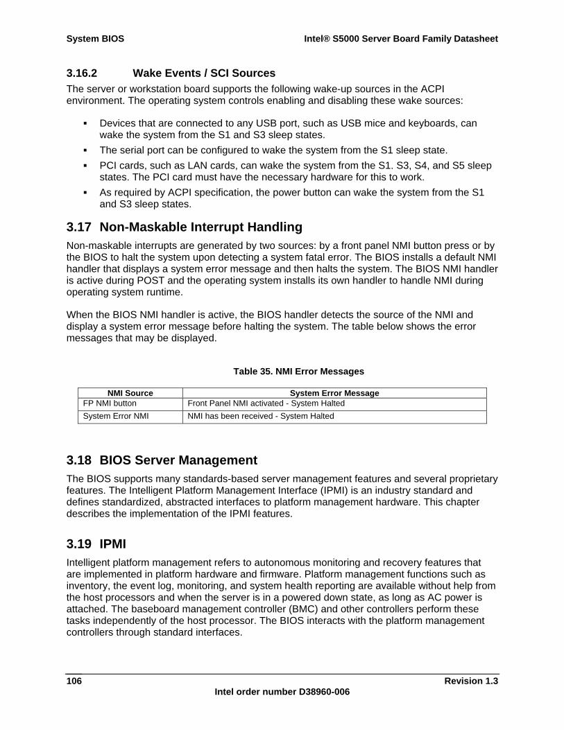
System BIOS Intel® S5000 Server Board Family Datasheet
Revision 1.3 Intel order number D38960-006
106
3.16.2 Wake Events / SCI Sources The server or workstation board supports the following wake-up sources in the ACPI environment. The operating system controls enabling and disabling these wake sources:
Devices that are connected to any USB port, such as USB mice and keyboards, can wake the system from the S1 and S3 sleep states.
The serial port can be configured to wake the system from the S1 sleep state. PCI cards, such as LAN cards, can wake the system from the S1. S3, S4, and S5 sleep
states. The PCI card must have the necessary hardware for this to work. As required by ACPI specification, the power button can wake the system from the S1
and S3 sleep states.
3.17 Non-Maskable Interrupt Handling Non-maskable interrupts are generated by two sources: by a front panel NMI button press or by the BIOS to halt the system upon detecting a system fatal error. The BIOS installs a default NMI handler that displays a system error message and then halts the system. The BIOS NMI handler is active during POST and the operating system installs its own handler to handle NMI during operating system runtime.
When the BIOS NMI handler is active, the BIOS handler detects the source of the NMI and display a system error message before halting the system. The table below shows the error messages that may be displayed.
Table 35. NMI Error Messages
NMI Source System Error Message FP NMI button Front Panel NMI activated - System Halted System Error NMI NMI has been received - System Halted
3.18 BIOS Server Management The BIOS supports many standards-based server management features and several proprietary features. The Intelligent Platform Management Interface (IPMI) is an industry standard and defines standardized, abstracted interfaces to platform management hardware. This chapter describes the implementation of the IPMI features.
3.19 IPMI Intelligent platform management refers to autonomous monitoring and recovery features that are implemented in platform hardware and firmware. Platform management functions such as inventory, the event log, monitoring, and system health reporting are available without help from the host processors and when the server is in a powered down state, as long as AC power is attached. The baseboard management controller (BMC) and other controllers perform these tasks independently of the host processor. The BIOS interacts with the platform management controllers through standard interfaces.
Intel® S5000 Server Board Family Datasheet System BIOS
Revision 1.3 Intel order number D38960-006
107
The BIOS enables the system interface to the BMC in early POST. The BIOS logs system events and POST error codes during the system operation. The BIOS logs a boot event to BMC early in POST. The events logged by the BIOS follow the Intelligent Platform Management Interface Specification, Version 2.0.
3.20 Console Redirection The BIOS supports redirection of both video and keyboard via a serial link (serial port). When console redirection is enabled, the local (host server) keyboard input and video output are passed both to the local keyboard and video connections, and to the remote console through the serial link. Keyboard inputs from both sources are considered valid and video is displayed to both outputs.
As an option, the system can be operated without a host keyboard or monitor attached to the system and run entirely via the remote console. Utilities that can be executed remotely include BIOS Setup.
3.20.1 Serial Configuration Settings The BIOS does not require that the splash logo be turned off for console redirection to function. The BIOS supports multiple consoles, some of which are in graphics mode and some in text mode.
Console redirection ends at the beginning of the legacy operating system boot. The operating system is responsible for continuing the redirection from that point.
3.20.2 Keystroke Mappings During console redirection, the remote terminal sends keystrokes to the local server. The remote terminal can be a dumb terminal with a direct connection and running a communication program. The keystroke mappings follow VT-UTF8 format with the following extensions.
3.20.2.1 Setup Alias Keys The <Del> and <Ctrl>-function key combinations are synonyms for the <F2> or “Setup” key. They are implemented and documented, but are not be prompted for in screen messages. These hot keys are defined for console redirection support, and are not be implemented for locally attached keyboards.
3.20.2.2 Standalone <Esc> Key for Headless Operation The Microsoft Headless Design Guidelines describes a specific implementation for the <Esc> key as a single standalone keystroke:
<Esc> followed by a two-second pause must be interpreted as a single escape. <Esc> followed within two seconds by one or more characters that do not form a
sequence described in this specification must be interpreted as <Esc> plus the character or characters, not as an escape sequence.
The escape sequence in the following table is an input sequence. This means it is sent to the BIOS from the remote terminal.
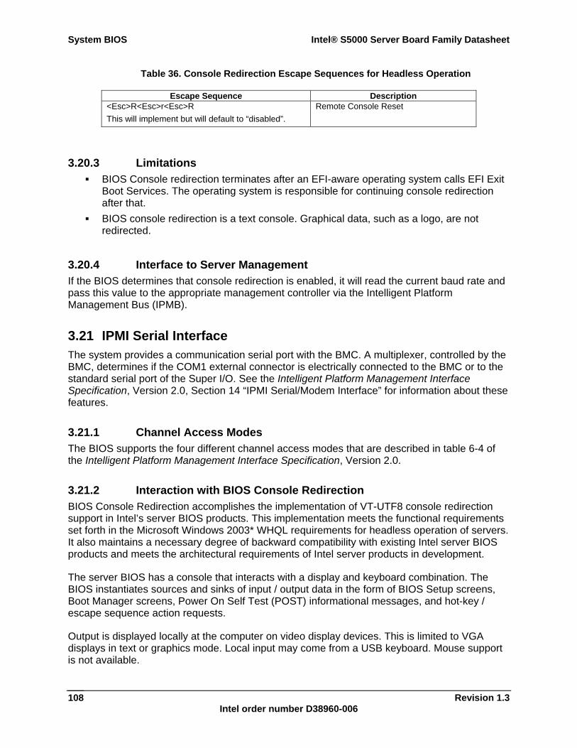
System BIOS Intel® S5000 Server Board Family Datasheet
Revision 1.3 Intel order number D38960-006
108
Table 36. Console Redirection Escape Sequences for Headless Operation
Escape Sequence Description <Esc>R<Esc>r<Esc>R This will implement but will default to “disabled”.
Remote Console Reset
3.20.3 Limitations BIOS Console redirection terminates after an EFI-aware operating system calls EFI Exit
Boot Services. The operating system is responsible for continuing console redirection after that.
BIOS console redirection is a text console. Graphical data, such as a logo, are not redirected.
3.20.4 Interface to Server Management If the BIOS determines that console redirection is enabled, it will read the current baud rate and pass this value to the appropriate management controller via the Intelligent Platform Management Bus (IPMB).
3.21 IPMI Serial Interface The system provides a communication serial port with the BMC. A multiplexer, controlled by the BMC, determines if the COM1 external connector is electrically connected to the BMC or to the standard serial port of the Super I/O. See the Intelligent Platform Management Interface Specification, Version 2.0, Section 14 “IPMI Serial/Modem Interface” for information about these features.
3.21.1 Channel Access Modes The BIOS supports the four different channel access modes that are described in table 6-4 of the Intelligent Platform Management Interface Specification, Version 2.0.
3.21.2 Interaction with BIOS Console Redirection BIOS Console Redirection accomplishes the implementation of VT-UTF8 console redirection support in Intel’s server BIOS products. This implementation meets the functional requirements set forth in the Microsoft Windows 2003* WHQL requirements for headless operation of servers. It also maintains a necessary degree of backward compatibility with existing Intel server BIOS products and meets the architectural requirements of Intel server products in development.
The server BIOS has a console that interacts with a display and keyboard combination. The BIOS instantiates sources and sinks of input / output data in the form of BIOS Setup screens, Boot Manager screens, Power On Self Test (POST) informational messages, and hot-key / escape sequence action requests.
Output is displayed locally at the computer on video display devices. This is limited to VGA displays in text or graphics mode. Local input may come from a USB keyboard. Mouse support is not available.
Intel® S5000 Server Board Family Datasheet System BIOS
Revision 1.3 Intel order number D38960-006
109
The use of serial port console redirection allows a single serial cable to be used for each server system. The serial cables from a number of servers can be connected to a serial concentrator or to a switch. This allows access to each individual server system. The system administrator can remotely switch from one server to another to manage large numbers of servers.
Through the redirection capabilities of the BMC on Intel® platforms, the serial port UART input / output stream can be further redirected and sent over a platform LAN device as a packetized serial byte stream. This BMC function is called Serial over LAN (SOL). It further optimizes space requirements and server management capability.
Additional features are available if BIOS for console redirection is enabled on the same COM port as the channel access serial port, and if the Channel Access Mode is set to either Always Active or Preboot.
BIOS console redirection supports an extra control escape sequence to force the COM port to the BMC. After this command is sent, the COM1 port attaches to the BMC Channel Access serial port and Super I/O COM1 data is ignored. This feature allows a remote user to monitor the status of POST using the standard BIOS console redirection features and then take control of the system reset or power using the Channel Mode features. If a failure occurs during POST, a watchdog time-out feature in the BMC automatically takes control of the COM1 port.
The character sequence that switches the multiplexer to the BMC serial port is “ESC O 9” (denoted as ^[O9). This key sequence is above the normal ANSI function keys and is not used by an ANSI terminal.
3.22 Wired For Management (WFM) Wired for Management is an industry-wide initiative to increase overall manageability and reduce total cost of ownership. WFM allows a server to be managed over a network. The system BIOS supports the System Management BIOS Reference Specification, Version 2.4 to help higher-level instrumentation software meet the Wired For Management Baseline Specification, Revision 2.0 requirements.
3.22.1 PXE BIOS Support The BIOS supports the EFI PXE implementation as specified in Chapter 15 of the Extensible Firmware Interface Reference Specification, Version 1.1. To utilize this, the user must load EFI Simple Network Protocol driver and the UNDI driver specific for the network interface card being used. The UNDI driver should be included with the network interface card. The Simple Network Protocol driver can be obtained from http://developer.intel.com/technology/framework.
The BIOS supports legacy PXE option ROMs in legacy mode and includes the necessary PXE ROMs in the BIOS image for the onboard controllers. The legacy PXE ROM is required to boot a non-EFI operating system over the network.
3.23 System Management BIOS (SMBIOS) The BIOS provides support for the System Management BIOS Reference Specification, Version 2.4 to create a standardized interface for manageable attributes that are expected to be supported by DMI-enabled computer systems. The BIOS provides this interface via data structures through which the system attributes are reported. Using SMBIOS, a system

System BIOS Intel® S5000 Server Board Family Datasheet
Revision 1.3 Intel order number D38960-006
110
administrator can obtain the types, capabilities, operational status, installation date and other information about the server components.
Intel® S5000 Server Board Family Datasheet System Management
Revision 1.3 Intel order number D38960-006
111
4. System Management
4.1 Feature Support This section provides a high-level list of management features supported by the Intel® 631xESB / 632xESB I/O Controller Hub BMC.
4.1.1 Legacy Features These features are carried over from previous platforms with little or no change in functionality.
4.1.1.1 IPMI 2.0 Features See the IPMI 2.0 Specification for more information on the features listed in this section.
Baseboard management controller (BMC) functionality Watchdog timer Messaging support – Includes command bridging and user/session support. Chassis device functionality – Includes power / reset control and BIOS boot flags
support. Alert processing device – Includes Platform Event Trap (PET) SNMP alerts via LAN
interfaces. Platform event filtering (PEF) device functionality. Event receiver device functionality – The BMC receives and processes events from
other platform subsystems. Field replaceable unit (FRU) inventory device functionality – The BMC supports access
to system FRU devices using IPMI FRU commands. System event log (SEL) device functionality – The BMC supports and provides access to
a SEL. Sensor device record (SDR) repository device functionality – The BMC supports storage
and access of system SDRs. Sensor device and sensor scanning / monitoring– The BMC provides IPMI management
of system sensors. The BMC polls various platform sensors for the purpose of monitoring and reporting system health. These include soft sensors used for reporting system state and events, as well as hardware sensor monitoring.
IPMI interfaces: - Host Interfaces – Includes SMS (with “receive message queue” support) and SMM
interfaces. - Serial- Interface – Basic mode and terminal mode support. - PCI-SMBus Interface – Allows plug-in PCI cards to send commands to BMC via
IPMB-like command protocol. - IPMB Interface - LAN Interfaces – Supports IPMI over LAN protocol (RMCP, RMCP+)
System Management Intel® S5000 Server Board Family Datasheet
Revision 1.3 Intel order number D38960-006
112
Serial Over LAN (SOL) ACPI state synchronization – The BMC tracks ACPI state changes (provided by BIOS). BMC self test – The BMC performs initialization and run-time self tests and makes
results available to external entities.
4.1.1.2 Non-IPMI Features This section lists non-IPMI feature support carried over from prior generation of servers.
PSMI 1.44-compliant power system monitoring, including support for power gauge and power nozzle sensors. Prior generation platforms supported PSMI 1.42, which was very similar to PSMI 1.44).
Fault resilient booting (FRB) support – FRB2 is supported via watchdog timer functionality.
BMC firmware update using firmware transfer mode operation BMC on-line update – BMC rolling update, which supports a redundant firmware image. Power state retention Chassis intrusion detection is supported on some platforms FRU fault LED support – The BMC lights server LEDs to indicate failed components. Basic fan control using TControl ver.1 SDRs. Fan redundancy monitoring and support Power supply redundancy monitoring and support Hot-swap fan support Signal testing support – The BMC provides test commands for setting or getting various
platform signal state Beep code generation – The BMC generates diagnostic beep codes for various fault
conditions Hot-swap backplane support – The BMC pushes power supply state to HSC System GUID storage and retrieval Front Panel management – The BMC controls system fault LED and chassis ID.
Supports secure lockout of certain front panel functionality. Monitors button presses. The chassis ID can be turned on via front panel button or command.
Power unit management – Support for power unit sensor. This handles power-good dropout condition.
NMI – Provides commands to set/get NMI source. Supports generation of NMI due to watchdog timer, IPMI command, or front panel NMI button. Monitors system NMI signal.
ARPs – The BMC can send and respond to ARP. This is supported on Intel® 631xESB / 632xESB I/O Controller Hub embedded NICs
DHCP – The BMC can perform DHCP. This is supported on Intel® 631xESB / 632xESB I/O Controller Hub embedded NICs

Intel® S5000 Server Board Family Datasheet System Management
Revision 1.3 Intel order number D38960-006
113
4.1.2 New Features This section lists features that are being introduced on server boards that use the Intel® 5000 Series Chipsets.
Acoustic management – Improved acoustic levels are achieved by including support for fan profiles using TControl ver2 SDRs.
BMC timeclock sync with SIO RTC – At BMC startup, the BMC reads SIO RTC and updates its internal timeclock to match.
Chassis intrusion fan interactions – Fans go to high speed when chassis intrusion signal is asserted. This is provided on platforms that have chassis intrusion support.
Intel® Remote Management Module (Intel® RMM) support. This card utilizes its own dedicated NIC (Intel® RMM NIC) to provide advanced server management features that work in conjunction with the BMC. This support includes the following: - BMC usage of Intel® RMM NIC via Fast Management Link (FML). The FML is used
as an extra NIC channel to the BMC. The BMC can support IPMI over LAN and SOL using this interface.
- BMC forwarding of event log messages to the Intel® RMM.
4.2 Power System The BMC is not directly in the system power control path but it does have the capability of blocking power control actions due to front panel power button presses or chipset initiated power state changes. It can generate power state changes by simulating a front panel power button press. It monitors both the requested power state from the chipset and the actual power good state.
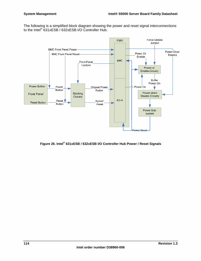
System Management Intel® S5000 Server Board Family Datasheet
Revision 1.3 Intel order number D38960-006
114
The following is a simplified block diagram showing the power and reset signal interconnections to the Intel® 631xESB / 632xESB I/O Controller Hub.
Figure 26. Intel® 631xESB / 632xESB I/O Controller Hub Power / Reset Signals
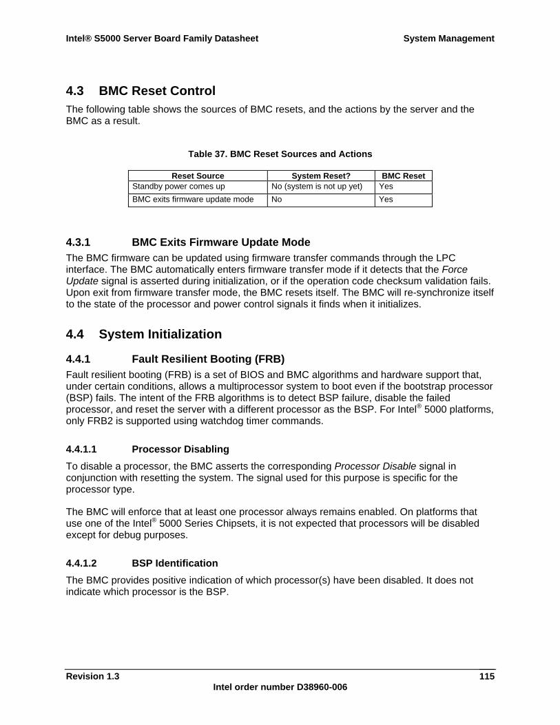
Intel® S5000 Server Board Family Datasheet System Management
Revision 1.3 Intel order number D38960-006
115
4.3 BMC Reset Control The following table shows the sources of BMC resets, and the actions by the server and the BMC as a result.
Table 37. BMC Reset Sources and Actions
Reset Source System Reset? BMC Reset Standby power comes up No (system is not up yet) Yes BMC exits firmware update mode No Yes
4.3.1 BMC Exits Firmware Update Mode The BMC firmware can be updated using firmware transfer commands through the LPC interface. The BMC automatically enters firmware transfer mode if it detects that the Force Update signal is asserted during initialization, or if the operation code checksum validation fails. Upon exit from firmware transfer mode, the BMC resets itself. The BMC will re-synchronize itself to the state of the processor and power control signals it finds when it initializes.
4.4 System Initialization
4.4.1 Fault Resilient Booting (FRB) Fault resilient booting (FRB) is a set of BIOS and BMC algorithms and hardware support that, under certain conditions, allows a multiprocessor system to boot even if the bootstrap processor (BSP) fails. The intent of the FRB algorithms is to detect BSP failure, disable the failed processor, and reset the server with a different processor as the BSP. For Intel® 5000 platforms, only FRB2 is supported using watchdog timer commands.
4.4.1.1 Processor Disabling To disable a processor, the BMC asserts the corresponding Processor Disable signal in conjunction with resetting the system. The signal used for this purpose is specific for the processor type.
The BMC will enforce that at least one processor always remains enabled. On platforms that use one of the Intel® 5000 Series Chipsets, it is not expected that processors will be disabled except for debug purposes.
4.4.1.2 BSP Identification The BMC provides positive indication of which processor(s) have been disabled. It does not indicate which processor is the BSP.
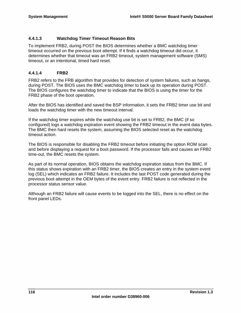
System Management Intel® S5000 Server Board Family Datasheet
Revision 1.3 Intel order number D38960-006
116
4.4.1.3 Watchdog Timer Timeout Reason Bits To implement FRB2, during POST the BIOS determines whether a BMC watchdog timer timeout occurred on the previous boot attempt. If it finds a watchdog timeout did occur, it determines whether that timeout was an FRB2 timeout, system management software (SMS) timeout, or an intentional, timed hard reset.
4.4.1.4 FRB2 FRB2 refers to the FRB algorithm that provides for detection of system failures, such as hangs, during POST. The BIOS uses the BMC watchdog timer to back up its operation during POST. The BIOS configures the watchdog timer to indicate that the BIOS is using the timer for the FRB2 phase of the boot operation.
After the BIOS has identified and saved the BSP information, it sets the FRB2 timer use bit and loads the watchdog timer with the new timeout interval.
If the watchdog timer expires while the watchdog use bit is set to FRB2, the BMC (if so configured) logs a watchdog expiration event showing the FRB2 timeout in the event data bytes. The BMC then hard resets the system, assuming the BIOS selected reset as the watchdog timeout action.
The BIOS is responsible for disabling the FRB2 timeout before initiating the option ROM scan and before displaying a request for a boot password. If the processor fails and causes an FRB2 time-out, the BMC resets the system.
As part of its normal operation, BIOS obtains the watchdog expiration status from the BMC. If this status shows expiration with an FRB2 timer, the BIOS creates an entry in the system event log (SEL) which indicates an FRB2 failure. It includes the last POST code generated during the previous boot attempt in the OEM bytes of the event entry. FRB2 failure is not reflected in the processor status sensor value.
Although an FRB2 failure will cause events to be logged into the SEL, there is no effect on the front panel LEDs.
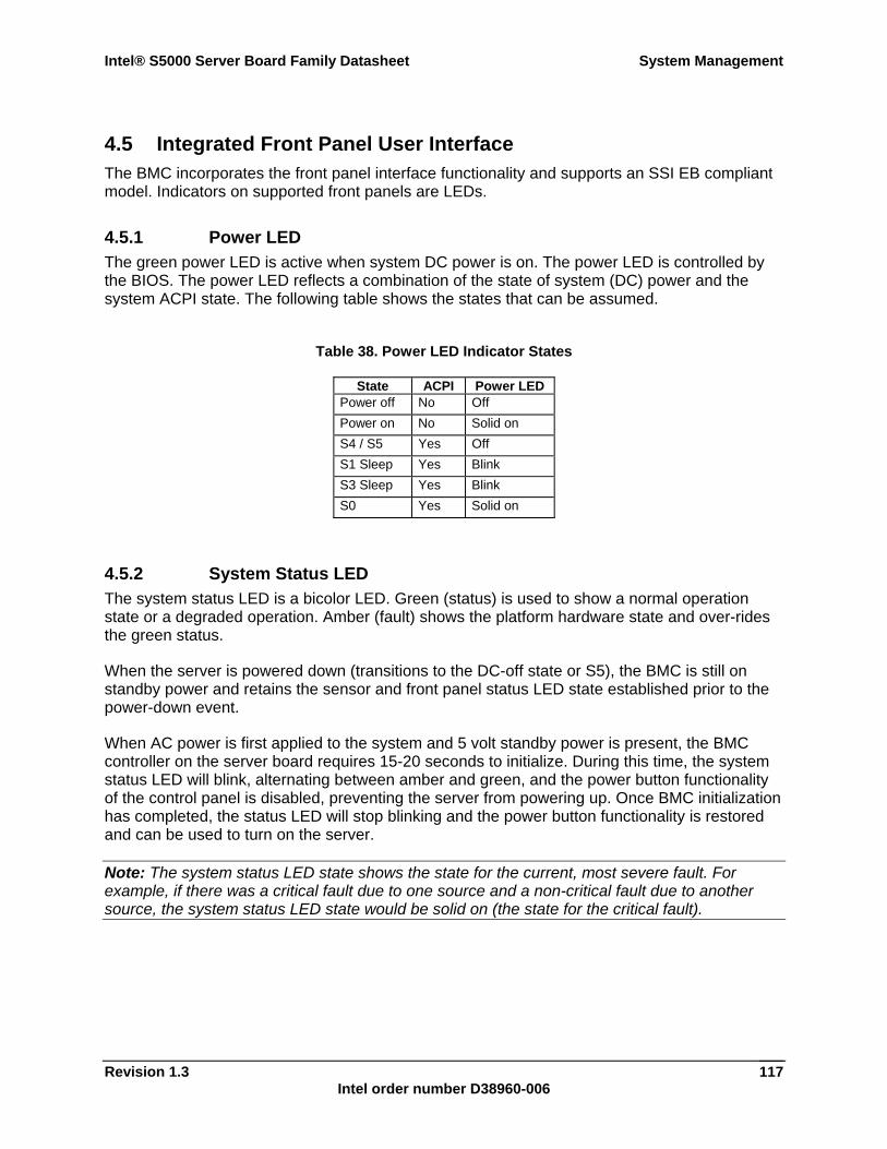
Intel® S5000 Server Board Family Datasheet System Management
Revision 1.3 Intel order number D38960-006
117
4.5 Integrated Front Panel User Interface The BMC incorporates the front panel interface functionality and supports an SSI EB compliant model. Indicators on supported front panels are LEDs.
4.5.1 Power LED The green power LED is active when system DC power is on. The power LED is controlled by the BIOS. The power LED reflects a combination of the state of system (DC) power and the system ACPI state. The following table shows the states that can be assumed.
Table 38. Power LED Indicator States
State ACPI Power LED Power off No Off Power on No Solid on S4 / S5 Yes Off S1 Sleep Yes Blink S3 Sleep Yes Blink S0 Yes Solid on
4.5.2 System Status LED The system status LED is a bicolor LED. Green (status) is used to show a normal operation state or a degraded operation. Amber (fault) shows the platform hardware state and over-rides the green status.
When the server is powered down (transitions to the DC-off state or S5), the BMC is still on standby power and retains the sensor and front panel status LED state established prior to the power-down event.
When AC power is first applied to the system and 5 volt standby power is present, the BMC controller on the server board requires 15-20 seconds to initialize. During this time, the system status LED will blink, alternating between amber and green, and the power button functionality of the control panel is disabled, preventing the server from powering up. Once BMC initialization has completed, the status LED will stop blinking and the power button functionality is restored and can be used to turn on the server.
Note: The system status LED state shows the state for the current, most severe fault. For example, if there was a critical fault due to one source and a non-critical fault due to another source, the system status LED state would be solid on (the state for the critical fault).
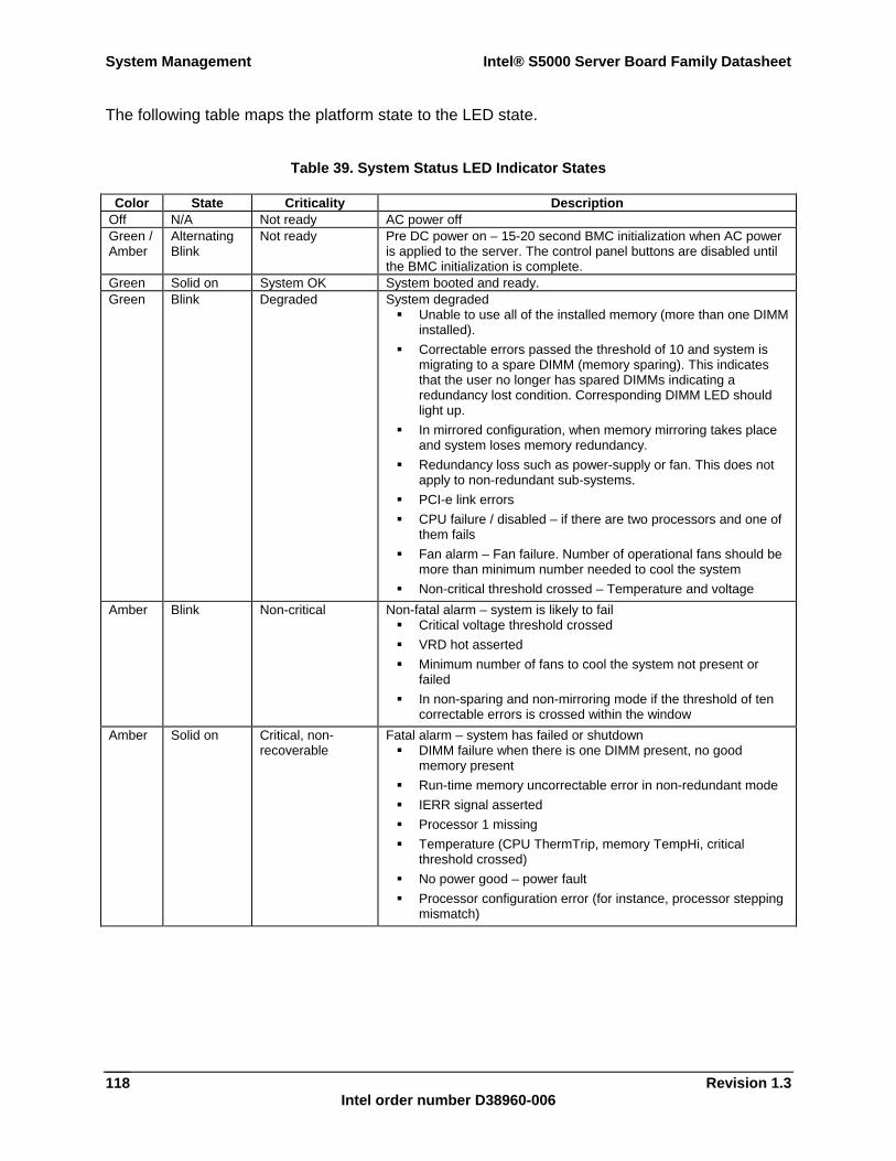
System Management Intel® S5000 Server Board Family Datasheet
Revision 1.3 Intel order number D38960-006
118
The following table maps the platform state to the LED state.
Table 39. System Status LED Indicator States
Color State Criticality Description Off N/A Not ready AC power off Green / Amber
Alternating Blink
Not ready Pre DC power on – 15-20 second BMC initialization when AC power is applied to the server. The control panel buttons are disabled until the BMC initialization is complete.
Green Solid on System OK System booted and ready. Green Blink Degraded System degraded
Unable to use all of the installed memory (more than one DIMM installed).
Correctable errors passed the threshold of 10 and system is migrating to a spare DIMM (memory sparing). This indicates that the user no longer has spared DIMMs indicating a redundancy lost condition. Corresponding DIMM LED should light up.
In mirrored configuration, when memory mirroring takes place and system loses memory redundancy.
Redundancy loss such as power-supply or fan. This does not apply to non-redundant sub-systems.
PCI-e link errors CPU failure / disabled – if there are two processors and one of
them fails Fan alarm – Fan failure. Number of operational fans should be
more than minimum number needed to cool the system Non-critical threshold crossed – Temperature and voltage
Amber Blink Non-critical Non-fatal alarm – system is likely to fail Critical voltage threshold crossed VRD hot asserted Minimum number of fans to cool the system not present or
failed In non-sparing and non-mirroring mode if the threshold of ten
correctable errors is crossed within the window Amber Solid on Critical, non-
recoverable Fatal alarm – system has failed or shutdown
DIMM failure when there is one DIMM present, no good memory present
Run-time memory uncorrectable error in non-redundant mode IERR signal asserted Processor 1 missing Temperature (CPU ThermTrip, memory TempHi, critical
threshold crossed) No power good – power fault Processor configuration error (for instance, processor stepping
mismatch)
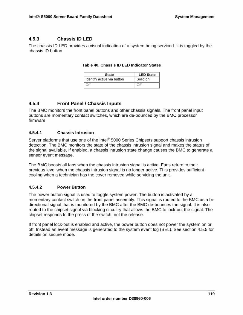
Intel® S5000 Server Board Family Datasheet System Management
Revision 1.3 Intel order number D38960-006
119
4.5.3 Chassis ID LED The chassis ID LED provides a visual indication of a system being serviced. It is toggled by the chassis ID button
Table 40. Chassis ID LED Indicator States
State LED State Identify active via button Solid on Off Off
4.5.4 Front Panel / Chassis Inputs The BMC monitors the front panel buttons and other chassis signals. The front panel input buttons are momentary contact switches, which are de-bounced by the BMC processor firmware.
4.5.4.1 Chassis Intrusion Server platforms that use one of the Intel® 5000 Series Chipsets support chassis intrusion detection. The BMC monitors the state of the chassis intrusion signal and makes the status of the signal available. If enabled, a chassis intrusion state change causes the BMC to generate a sensor event message.
The BMC boosts all fans when the chassis intrusion signal is active. Fans return to their previous level when the chassis intrusion signal is no longer active. This provides sufficient cooling when a technician has the cover removed while servicing the unit.
4.5.4.2 Power Button The power button signal is used to toggle system power. The button is activated by a momentary contact switch on the front panel assembly. This signal is routed to the BMC as a bi-directional signal that is monitored by the BMC after the BMC de-bounces the signal. It is also routed to the chipset signal via blocking circuitry that allows the BMC to lock-out the signal. The chipset responds to the press of the switch, not the release.
If front panel lock-out is enabled and active, the power button does not power the system on or off. Instead an event message is generated to the system event log (SEL). See section 4.5.5 for details on secure mode.
System Management Intel® S5000 Server Board Family Datasheet
Revision 1.3 Intel order number D38960-006
120
4.5.4.3 Reset Button An assertion of the front panel reset signal to the BMC causes the system to start the reset and reboot process, as long as the BMC has not locked-out this input. This assertion is immediate and without the cooperation from software or the operating system.
The reset button is a momentary contact button on the front panel. Its signal is routed through the front panel connector to the BMC, which monitors and de-bounces it.
If front panel lock-out is enabled, the reset button does not reset the system. Instead an event message is generated to the SEL.
4.5.4.4 Diagnostic Interrupt (Front Panel NMI) As stated in the IPMI 2.0 specification, “a diagnostic interrupt is a non-maskable interrupt or signal for generating diagnostic traces and ‘core dumps’ from the operating system.” For platforms that use one of the Intel® 5000 Series Chipsets, this is an NMI.
The diagnostic interrupt button is connected to the BMC through the front panel connector. A diagnostic interrupt button press causes the BMC to do the following:
Generate a critical event message. Generate a system NMI pulse.
After an NMI has been generated by the BMC, the BMC will not generate another until the system has been reset or powered down.
The BMC automatically clears the OEM 1 message flag and NMI sources whenever it detects a system reset, or is itself reset. The diagnostic interrupt button is not disabled or otherwise affected when the system is in front panel lock-out mode.
4.5.4.5 Chassis Identify The front panel chassis identify button toggles the state of the chassis ID LED. If the LED is off, then pushing the chassis identify button lights the LED. The LED remains lit until the button is pushed again.
4.5.5 Front Panel Lock-out Operation The front panel lock-out feature allows the front panel buttons to be protected against unauthorized use or access. Front panel lock-out mode is enabled and controlled by the system BIOS. When front panel lock-out is enabled and active, and a protected front panel button is pressed, an event is generated.
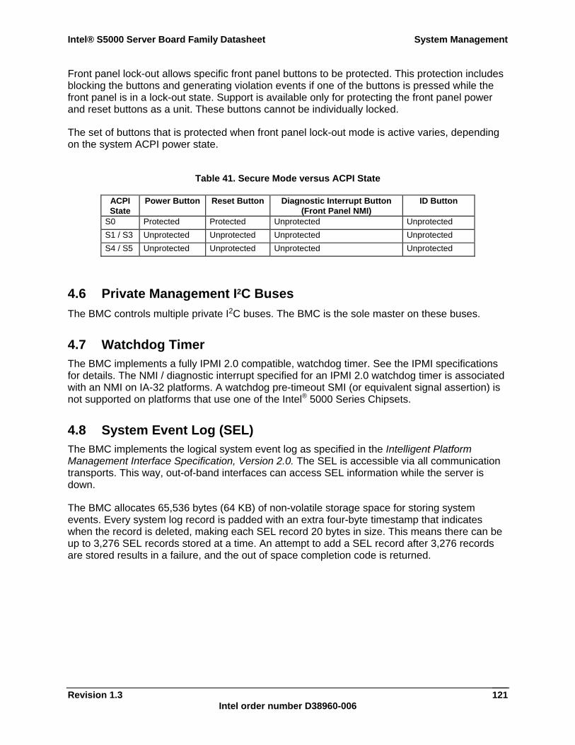
Intel® S5000 Server Board Family Datasheet System Management
Revision 1.3 Intel order number D38960-006
121
Front panel lock-out allows specific front panel buttons to be protected. This protection includes blocking the buttons and generating violation events if one of the buttons is pressed while the front panel is in a lock-out state. Support is available only for protecting the front panel power and reset buttons as a unit. These buttons cannot be individually locked.
The set of buttons that is protected when front panel lock-out mode is active varies, depending on the system ACPI power state.
Table 41. Secure Mode versus ACPI State
ACPI State
Power Button Reset Button Diagnostic Interrupt Button (Front Panel NMI)
ID Button
S0 Protected Protected Unprotected Unprotected S1 / S3 Unprotected Unprotected Unprotected Unprotected S4 / S5 Unprotected Unprotected Unprotected Unprotected
4.6 Private Management I2C Buses The BMC controls multiple private I2C buses. The BMC is the sole master on these buses.
4.7 Watchdog Timer The BMC implements a fully IPMI 2.0 compatible, watchdog timer. See the IPMI specifications for details. The NMI / diagnostic interrupt specified for an IPMI 2.0 watchdog timer is associated with an NMI on IA-32 platforms. A watchdog pre-timeout SMI (or equivalent signal assertion) is not supported on platforms that use one of the Intel® 5000 Series Chipsets.
4.8 System Event Log (SEL) The BMC implements the logical system event log as specified in the Intelligent Platform Management Interface Specification, Version 2.0. The SEL is accessible via all communication transports. This way, out-of-band interfaces can access SEL information while the server is down.
The BMC allocates 65,536 bytes (64 KB) of non-volatile storage space for storing system events. Every system log record is padded with an extra four-byte timestamp that indicates when the record is deleted, making each SEL record 20 bytes in size. This means there can be up to 3,276 SEL records stored at a time. An attempt to add a SEL record after 3,276 records are stored results in a failure, and the out of space completion code is returned.
System Management Intel® S5000 Server Board Family Datasheet
Revision 1.3 Intel order number D38960-006
122
4.8.1 Servicing Events Events can be received while the SEL is being cleared. The BMC implements an event message queue to avoid the loss of messages. Queued messages are not overwritten.
The BMC recognizes duplicate event messages by comparing sequence numbers and the message source. For more information, see the IPMI 2.0 Specification. Duplicate event messages are discarded (filtered) by the BMC after they are read from the event message queue. This means the queue can contain duplicate messages.
4.8.2 SEL Erasure SEL erasure is a background process. SEL events that arrive during the erasure process will be queued until the erasure is complete and then committed to the SEL.
SEL erasure generates an event logging disabled sensor event.
4.8.3 Timestamp Clock The BMC maintains a four-byte internal timestamp clock used by the SEL and sensor data record (SDR) sub-systems. This clock is incremented once per second.
4.8.3.1 Clock Initialization and Synchronization If the BMC loses standby power, then when the power is restored, the BMC reads the real-time clock (RTC) in the SIO chip and uses this value to update the BMC’s internal system clock. The clock is used for SEL timestamps and programmed system wake-ups.
The actual system clock used by the BIOS and the operating system is based on a RTC in the Intel® 5000 Series Chipsets’ ICH component, not on the component in the SIO that the BMC uses to initialize its clock. As a result, it is possible for synchronization issues to exist between the BMC clock and the real-time clock. In some situations, the BIOS updates the BMC clock. This alleviates possible mismatch problems as described below:
System boot: At each system boot, the BIOS checks the BMC timestamp clock and only updates this clock if the time is inaccurate. This reduces extra SEL entries.
SMI handler: The BIOS programs the chipset to generate an SMI when the operating system is shutting down (transition to S3, S4, or S5). This is necessary to download the sleep state information to BMC. During this SMI, the BIOS will read the time from the system RTC and then update BMC clock.
Whenever the BMC receives the Set SEL Time command, it updates the private RTC in the SIO to match the system time. That helps ensure that the BMC RTC is in sync with system RTC.
If the system time (for instance, set through an operating system interface) is changed, the BMC time clock will not be re-synchronized until the operating system shuts down the server, or, in case of a non-graceful shutdown, when the server is rebooted.
Intel® S5000 Server Board Family Datasheet System Management
Revision 1.3 Intel order number D38960-006
123
4.9 Sensor Data Record (SDR) Repository The BMC implements the logical sensor data record (SDR) repository as specified in the Intelligent Platform Management Interface Specification, Version 2.0 The SDR repository is accessible via all communication transports. This way, out-of-band interfaces can access SDR repository information while the system is down.
The BMC allocates 65,536 bytes (64 KB) of non-volatile storage space for the SDR.
4.9.1 Initialization Agent The BMC implements the internal sensor initialization agent functionality specified in the Intelligent Platform Management Interface Specification, Version 2.0. When the BMC initializes upon a system boot, it scans the SDR repository and configures the IPMB devices that have management controller records. This includes setting sensor thresholds, enabling or disabling sensor event message scanning, and enabling or disabling sensor event messages.
The initialization process causes those IPMB micro-controllers to rearm their event generation. In some cases, this causes a duplicate event to be sent to the BMC. The BMC’s mechanism to detect and delete duplicate events should prevent any duplicate event messages from being logged.
4.10 Field Replaceable Unit (FRU) Inventory Device The BMC implements the interface for logical FRU inventory devices as specified in the Intelligent Platform Management Interface Specification, Version 2.0. This functionality provides commands used for accessing and managing the FRU inventory information. These commands can be delivered via all interfaces.
The BMC provides FRU device command access to its own FRU device, and to the FRU devices throughout the server. The BMC controls the mapping of the FRU device ID to the physical device. In accordance with the IPMI specification, FRU device 0 is always located on the server board.
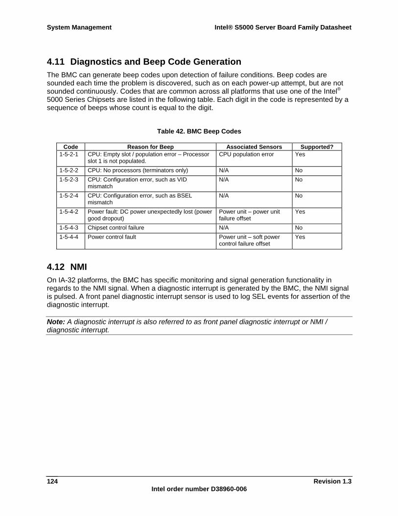
System Management Intel® S5000 Server Board Family Datasheet
Revision 1.3 Intel order number D38960-006
124
4.11 Diagnostics and Beep Code Generation The BMC can generate beep codes upon detection of failure conditions. Beep codes are sounded each time the problem is discovered, such as on each power-up attempt, but are not sounded continuously. Codes that are common across all platforms that use one of the Intel® 5000 Series Chipsets are listed in the following table. Each digit in the code is represented by a sequence of beeps whose count is equal to the digit.
Table 42. BMC Beep Codes
Code Reason for Beep Associated Sensors Supported? 1-5-2-1 CPU: Empty slot / population error – Processor
slot 1 is not populated. CPU population error Yes
1-5-2-2 CPU: No processors (terminators only) N/A No 1-5-2-3 CPU: Configuration error, such as VID
mismatch N/A No
1-5-2-4 CPU: Configuration error, such as BSEL mismatch
N/A No
1-5-4-2 Power fault: DC power unexpectedly lost (power good dropout)
Power unit – power unit failure offset
Yes
1-5-4-3 Chipset control failure N/A No 1-5-4-4 Power control fault Power unit – soft power
control failure offset Yes
4.12 NMI On IA-32 platforms, the BMC has specific monitoring and signal generation functionality in regards to the NMI signal. When a diagnostic interrupt is generated by the BMC, the NMI signal is pulsed. A front panel diagnostic interrupt sensor is used to log SEL events for assertion of the diagnostic interrupt.
Note: A diagnostic interrupt is also referred to as front panel diagnostic interrupt or NMI / diagnostic interrupt.
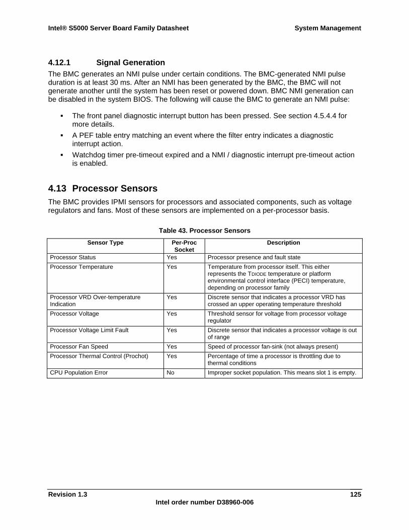
Intel® S5000 Server Board Family Datasheet System Management
Revision 1.3 Intel order number D38960-006
125
4.12.1 Signal Generation The BMC generates an NMI pulse under certain conditions. The BMC-generated NMI pulse duration is at least 30 ms. After an NMI has been generated by the BMC, the BMC will not generate another until the system has been reset or powered down. BMC NMI generation can be disabled in the system BIOS. The following will cause the BMC to generate an NMI pulse:
The front panel diagnostic interrupt button has been pressed. See section 4.5.4.4 for more details.
A PEF table entry matching an event where the filter entry indicates a diagnostic interrupt action.
Watchdog timer pre-timeout expired and a NMI / diagnostic interrupt pre-timeout action is enabled.
4.13 Processor Sensors The BMC provides IPMI sensors for processors and associated components, such as voltage regulators and fans. Most of these sensors are implemented on a per-processor basis.
Table 43. Processor Sensors
Sensor Type Per-Proc Socket
Description
Processor Status Yes Processor presence and fault state Processor Temperature Yes Temperature from processor itself. This either
represents the TDIODE temperature or platform environmental control interface (PECI) temperature, depending on processor family
Processor VRD Over-temperature Indication
Yes Discrete sensor that indicates a processor VRD has crossed an upper operating temperature threshold
Processor Voltage Yes Threshold sensor for voltage from processor voltage regulator
Processor Voltage Limit Fault Yes Discrete sensor that indicates a processor voltage is out of range
Processor Fan Speed Yes Speed of processor fan-sink (not always present) Processor Thermal Control (Prochot) Yes Percentage of time a processor is throttling due to
thermal conditions CPU Population Error No Improper socket population. This means slot 1 is empty.
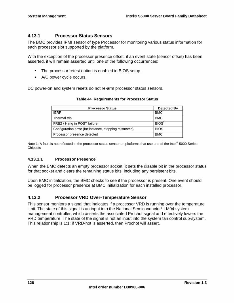
System Management Intel® S5000 Server Board Family Datasheet
Revision 1.3 Intel order number D38960-006
126
4.13.1 Processor Status Sensors The BMC provides IPMI sensor of type Processor for monitoring various status information for each processor slot supported by the platform.
With the exception of the processor presence offset, if an event state (sensor offset) has been asserted, it will remain asserted until one of the following occurrences:
The processor retest option is enabled in BIOS setup. A/C power cycle occurs.
DC power-on and system resets do not re-arm processor status sensors.
Table 44. Requirements for Processor Status
Processor Status Detected By IERR BMC Thermal trip BMC FRB2 / Hang in POST failure BIOS1 Configuration error (for instance, stepping mismatch) BIOS Processor presence detected BMC
Note 1: A fault is not reflected in the processor status sensor on platforms that use one of the Intel® 5000 Series Chipsets
4.13.1.1 Processor Presence When the BMC detects an empty processor socket, it sets the disable bit in the processor status for that socket and clears the remaining status bits, including any persistent bits.
Upon BMC initialization, the BMC checks to see if the processor is present. One event should be logged for processor presence at BMC initialization for each installed processor.
4.13.2 Processor VRD Over-Temperature Sensor This sensor monitors a signal that indicates if a processor VRD is running over the temperature limit. The state of this signal is an input into the National Semiconductor* LM94 system management controller, which asserts the associated Prochot signal and effectively lowers the VRD temperature. The state of the signal is not an input into the system fan control sub-system. This relationship is 1:1; if VRD-hot is asserted, then Prochot will assert.
Intel® S5000 Server Board Family Datasheet System Management
Revision 1.3 Intel order number D38960-006
127
4.13.3 ThermTrip Monitoring The BMC is responsible for persistently retaining ThermTrip history for each processor. This history tracks whether the processor has had a ThermTrip since the last processor sensor re-arm or retest.
When a thermal trip occurs, the BMC will poll the ThermTrip status for each processor. If the BMC has detected that a ThermTrip occurred, then it will set the ThermTrip offset for the applicable processor status sensor. The system hardware will then attempt to power down the server.
4.13.4 Platform Enviroment Control Interface (PECI) Support 4.13.4.1 PECI Temperature Value PECI temperature reading will be the current temperature reading relative to processor throttling temperature threshold. It is always be less than or equal to 0. As the temperature of the processor increases, the negative PECI reading will get smaller until it reaches 0 . When the processor temperature reaches or exceeds the Prochot temperature, the PECI temperature reading will remain at 0.
4.13.4.1.1 IPMI Sensor Support for PECI
Two temperature sensors per processor: Because these servers and workstations must support either non-PECI or PECI processors, this will be handled by defining two IPMI temperature sensors for each processor. One will be for PECI and one for thermal diode physical sensors. Only two of the temperature sensors will be enabled at a time (associated with PECI or thermal-diode), dependent on which sensor’s SDR is loaded on the system. PECI enabled processors only support the PECI SDR. When changing from non-PECI processors to PECI processors in a system the SDR must be re-loaded to get an accurate temperature reading.
IPMI sensor readings for PECI: IPMI processor temperature sensors that monitor thermal-diodes provide an absolute temperature value. However, when PECI processors are installed, the IPMI processor temperature sensors will provide relative values that are less than or equal to 0.
Detecting PECI sensors: The PECI sensors will be a type code (01h) = temperature and have a sensor maximum of 0 degrees C. If software needs to determine if a temperature sensor is a PECI sensor, it should convert the sensor maximum in the SDR and verify that the converted sensor maximum is 0 degrees C.
PECI sensor name: The PECI sensors are called Px Therm Margin on Intel S5000 systems, where the 'x' is the processor #. Example: Processor 1 would read P1 Therm Margin.
PECI thresholds: The PECI sensor will not have any thresholds assigned to this sensor
4.13.5 PROCHOT Support 4.13.5.1 PROCHOT Temperature Sensor On these servers and workstations, the PROCHOT sensor will be as an indication of the amount of time the processor spends in a throttled state, over a fixed period of time. Under normal operation, this sensor will read 0, indicating that the processor is not throttled. As the
System Management Intel® S5000 Server Board Family Datasheet
Revision 1.3 Intel order number D38960-006
128
processor increases in temperature, the amount of time the processor spends in a throttled state will increase, until 100% throttling is reached.
4.13.5.1.1 IPMI Sensor Support for PROCHOT
PROCHOT time window: The PROCHOT sensor measures the % of throttling on an individual processor over a 5.8 second time window.
Detecting PROCHOT sensors: The PROCHOT sensors will be a type code (01h) = temperature, but is read as a %. This is determined by reading bit 0 of the 'sensor units 1' field of the PROCHOT SDR. If bit 0 of this byte is 1b, then the sensor unit is read as a %. This is a standard method in IPMI to determine if a sensor is read as a %.
PROCHOT sensor name: The PROCHOT sensors are called Px Therm Ctrl % on Intel S5000 systems, where 'x' is the processor #. Example: Processor 1 would read P1 Therm Ctrl %.
PROCHOT thresholds: The PROCHOT sensors will have an upper critical threshold and should be treated as a normal threshold sensor.
4.13.6 IERR Monitoring The BMC monitors the IERR signal from each processor and maps this to the IERR offset of the associated processor status sensor.
4.13.7 Dynamic Processor Voltage Monitoring Processors support dynamic operating states in which the processor VIDs can change under program control or due to operating conditions. It is not feasible for the BMC to dynamically alter voltage thresholds for direct monitoring of the processor voltages. However, the National Semiconductor* LM94 system management controller device supports dynamic monitoring. The BMC reads a status register from the LM94 system management controller, which indicates if the processor voltage is within acceptable limits.
4.13.8 Processor Temperature Monitoring Processors used with platforms that use one of the Intel® 5000 Series Chipsets are multi-core and have one physical temperature sensor per core. The BMC aggregates the processor temperature or temperature offset (PECI enabled processor) sensing into one IPMI temperature sensor per socket. The higher of the two temperatures is used as the value of the IPMI sensor.
Intel® S5000 Server Board Family Datasheet System Management
Revision 1.3 Intel order number D38960-006
129
4.13.9 Processor Thermal Control Monitoring (Prochot) The BMC monitors processor thermal control monitoring for each processor. This functionality is provided by the National Semiconductor* LM94 system management controller device, which provides a reading of the percentage of time that the processor ProcHot signal is asserted over a given measurement window. The BMC implements this as a threshold sensor on a per-processor basis.
4.13.10 CPU Population Error Sensor The only processor population check that the BMC does is to verify that a processor is installed in slot 1. The hardware does not allow the server to power up in this state.
At BMC initialization, this sensor is first set to a de-asserted state. The BMC then checks for CPU population errors and sets the new value accordingly. If an error is detected and the SDR is so configured, a SEL event will be logged. The BMC checks for this fault condition and updates the sensor state at each attempt to DC power-on the system. At each DC power-on attempt, a beep code is generated if this fault is detected. BMC beep codes are listed in Table 42.
Note: This sensor is an auto-re-arm sensor but is not re-armed at system DC power-on or for system resets. The correct way to clear this sensor state is to correct the problem by AC powering down the server, installing a processor into slot 1, then AC powering on the server.
4.14 Standard Fan Management The BMC controls and monitors the system fans. For each fan, there is a fan speed sensor that provides fan failure detection. Some platforms also provide fan presence detection which the BMC maps into per-fan presence sensors. See the server or workstation Technical Product Specification that applies to your product for more information.
It is possible for the BMC to control the speed of some fans. Controllable fans are divided into fan domains in which there is a separate fan speed control for each domain and a separate fan control policy configurable for each domain.
A fan domain can have a set of temperature and fan sensors associated with it. These sensors are used to determine the current fan domain state. A fan domain has three states: sleep, nominal, and boost. The sleep and boost states have fixed, but configurable, fan speeds associated with them. The nominal state has a variable speed determined by the fan domain policy (see section 4.14.1, Nominal Fan Speed). An OEM SDR record is used to configure the fan domain policy (see Section 4.14.1).
Note: See the server or workstation Technical Product Specification that applies to your product for more information
The fan domain state is controlled by several factors. The following states are in order of precedence, from high to low:
System Management Intel® S5000 Server Board Family Datasheet
Revision 1.3 Intel order number D38960-006
130
Boost:
The associated fan in a critical or non-recoverable state in a non-redundant fan configuration.
The fan domain is a state of insufficient resources in a redundant fan configuration. Any temperature sensor in a critical or non-recoverable state, with the exception of
Processor Thermal Control Monitoring sensor (Prochot) or VRD Over-Temperature (VRDHot) sensors.
Sleep:
No boost conditions, system in ACPI S1 and S3 sleep states, and the BMC is configured to transition fan domains to sleep state.
Nominal:
See Section 4.14.1. 4.14.1 Nominal Fan Speed It is possible to configure a fan domain’s Nominal fan speed to be either static (fixed value) or controlled by the state of one or more associated temperature sensors.
OEM SDR records are used to configure which temperature sensors are associated with which fan control domains as well as the relationship (algorithm) between the temperature and fan speed control (PWM) value. Multiple OEM SDRs may reference / control the same fan control domain and multiple OEM SDRs may reference the same temperature sensors.
The PWM value for the given domain is computed using one or more instances of a stepwise linear algorithm and a clamp algorithm. The transition from one computed Nominal fan speed (PWM value) to a new one is ramped over time to avoid audible transitions. The ramp rate is configurable via the OEM SDR.
Multiple Additive and Clamp Controls can be defined for each fan domain and used simultaneously. For each domain, the BMC uses the maximum of all of the domain’s Stepwise Linear Control contributions and the sum of all of the domain’s Clamp Control contributions to computes the domain’s total PWM value, with the exception that a stepwise linear instance can be configured to provide the domain maximum at any time.
Hysteresis may be specified to minimize fan speed oscillation and also to smooth out fan speed transitions. Its application is described along with the fan contribution methods below. If a legacy TCONTROL SDR format does not allow specifying hysteresis, the BMC will assume a hysteresis value of zero.
4.14.2 Stepwise Linear
4.14.2.1 Fan Speed Contribution Each Stepwise Linear TCONTROL sub-record defines a lookup table that maps temperature sensor readings to fan speeds. The table entries must be in increasing order of temperature. The BMC walks the table, starting from the end, until it finds a temperature entry that is less
Intel® S5000 Server Board Family Datasheet System Management
Revision 1.3 Intel order number D38960-006
131
than or equal to the current reading of the temperature sensor. The corresponding fan speed is used as the domain fan contribution of that sub-record.
Hysteresis is applied to the difference calculated from the previously used reading to the current reading. If the difference is positive, the temperature is increasing and the specified positive hysteresis is subtracted. Otherwise, the change is negative or zero (non-positive), and the specified negative hysteresis is added.
If factoring in the hysteresis changes the calculated difference from positive to negative, or from non-positive to positive, the previously calculated contribution is used instead of recalculating the contribution. This is different from the IPMI sensor threshold interpretation of hysteresis, which is applied to threshold, but it has the desired effect of preventing oscillating fan speed behavior.
The basis for the final fan speed for each domain is the maximum of all calculated contributions of all Stepwise Linear TCONTROL sub-records that are valid under the active profile for that domain. All currently valid clamp contributions are added to this base value.
4.14.2.2 Domain Maximum Stepwise Linear TCONTROL sub-records might have a flag set that indicates that the instance provides the fan domain maximum PWM value. These sub-records do not contribute to the fan speed as described above. Instead, the fan speed obtained through the table lookup procedure is saved for later reference. When the final domain contribution is calculated, it will be reduced, if necessary, to this domain maximum value. Hysteresis is not applied to domain maximum sub-records.
4.14.3 Clamp Clamp TCONTROL sub-records specify a single temperature value and direct the BMC to increase the fan speed for the associated fan domain as necessary to maintain the value of the corresponding temperature sensor below the clamp value. When the sensor reading exceeds the clamp value, the fan speed contribution will increase over time until either the fan speed reaches maximum speed or the temperature reduces to below the threshold. If the temperature is below the threshold, the sensor’s contribution will be reduced over time until it goes to zero. Fan speed changes occur in the step size specified in the sub-record.
These sub-records allow a scan rate to be specified that will lower the frequency at which the sub-record’s contribution is recalculated. This can be used to allow time for the fan domain to react and increase the system cooling before increasing the fan speed again.
Hysteresis, if specified, is only applied when the contribution direction might change from positive to negative or vice versa. e.g., if the BMC previously increased the fan speed contribution from a given clamp sub-record, it will factor in any specified negative hysteresis when determining whether the “change direction” and start decreasing the fan contribution. If no action is taken due to hysteresis, the BMC continues to remember the previous direction.
The sum for all calculated contributions of all Clamp TCONTROL sub-records that are valid under the currently active profile for that domain will be added to the maximum of all currently valid stepwise linear contributions.
System Management Intel® S5000 Server Board Family Datasheet
Revision 1.3 Intel order number D38960-006
132
4.14.4 Sleep State Fan Control Using the Set ACPI Configuration Mode command, the BMC may be configured to set the fans to a fixed sleep state speed when the system is in the S1 sleep state.
4.14.5 Fan Redundancy Detection The BMC supports redundant fan monitoring and implements fan redundancy sensors. A fan redundancy sensor generates events when it’s associated set of fans transition between redundant and non-redundant states, as determined by the number and health of the component fans.
A single fan failure, or removal of a fan from a chassis that supports hot swap fans, in a redundant fan configuration is a non-critical failure and will be reflected in the front panel status as such.
4.14.6 Hot Swap Fan Support Some chassis and server boards provide support for hot-swap fans. These fans can be removed and replaced while the system is operating normally. The BMC implements fan presence sensors for each hot swappable fan. When a fan is replaced, the fan speed for the domain is temporarily set to high (kick-start) to ensure proper fan starting.
Note: See the server or workstation Technical Product Specification that applies to your product for more detailed information
4.15 Acoustic Management Acoustic management refers to enhanced fan management to keep the system optimally cooled while not creating unnecessary noise.
4.15.1 Fan Profiles The system can be configured through a BIOS setup screen option to give preference to meet the target acoustic level for the system at the expense of system performance, or to provide enhanced system performance at the expense of louder fans. This is accomplished with fan profiles. At the system boot, the BIOS will query the BMC to determine what fan profiles are supported. The BIOS indicates the chosen setup screen option to the BMC.
4.15.2 Interactions with DIMM Thermal Management
4.15.2.1 Thermal Profile Data The BIOS requires knowledge of various characteristics to use as input into its calculations for DIMM throttling setup. This is dependent on which fan profile is enabled. The BIOS retrieves this platform-specific information from the BMC at system boot.
The BMC supports this with Thermal Profile Data SDRs, which allow this data to be stored in the BMC’s SDR repository and can be customized per platform and per fan domain. On systems that support multiple profiles, each Thermal Profile SDR can apply to one or more profiles in a given fan domain.
Intel® S5000 Server Board Family Datasheet System Management
Revision 1.3 Intel order number D38960-006
133
4.16 PSMI Support Platforms that use the Intel® 5000 Series Chipsets support PSMI v1.44 compliant power supplies. Some power supplies may not support certain optional features, such as current monitoring.
4.17 System Memory RAS and Bus Error Monitoring System memory and bus error monitoring is done by the system BIOS. At startup, the BIOS checks the chipset for any memory errors early in the boot process. The BIOS updates the status of RAS configuration at startup and later at run time. BMC monitors and logs SEL events based on the SDR definitions. In addition, the BIOS help the BMC maintain the current DIMM presence and failure state and current memory RAS configuration (e.g., sparing, mirroring, RAID).
Support is provided for monitoring errors on system buses such as system bus errors and PCI bus errors. These are monitored by the BIOS, which generates critical interrupt sensor SEL events when the errors are detected.
The supported sensors are described below.
4.17.1 SMI Timeout Sensor For IA-32-based systems, the BMC supports an SMI Timeout Sensor (sensor type OEM (F3h), event type Discrete (03h)) that asserts if the SMI signal has been asserted for longer than a fixed time period (nominally 90 seconds for S5000 platforms). A continuously asserted SMI signal is an indication that the BIOS cannot service the condition that caused the SMI. This is usually because that condition prevents the BIOS from running.
When an SMI timeout occurs, the BMC takes the following actions:
It asserts the SMI timeout sensor and logs a SEL event for that sensor. It does an after-crash (post-mortem) system scan for uncorrectable memory and front-
side bus errors. Any uncorrectable ECC errors detected will be logged against a Memory sensor. Any uncorrectable bus errors will be logged against a Critical Interrupt sensor.
The standard behavior for BMC core firmware is to not initiate a system reset upon detection of an SMI timeout. This will be followed for S5000 platforms.
The BMC supports sensors for reporting post-mortem system memory errors and for DIMM presence, disabled state, and failure.
4.17.2 Memory Sensor The BMC supports one or more Memory type (0Ch) sensors that are event only. The sensors are only logged against by BMC detected errors (post-mortem) due to an SMI timeout event. Events will be event type specific (reading code 6Fh). The supported sensor offsets are:
01h – Uncorrectable ECC
System Management Intel® S5000 Server Board Family Datasheet
Revision 1.3 Intel order number D38960-006
134
4.17.3 Critical Interrupt Sensor The BMC implements a Critical Interrupt (13h) sensor for reporting the following conditions / events:
Bus Uncorrectable Error: Only sensed after an SMI timeout (post-mortem) Front Panel NMI / diagnostic interrupt: Monitored during normal system operation
4.17.4 DIMM Status Sensors There is one DIMM status sensor per DIMM slot. These sensors are IPMI sensor type Slot / Connector (21h) and event / reading type Sensor Specific (6Fh). The supported offsets are:
00h Fault Status Asserted 02h Device Installed 08h Device Disabled 09h Slot Holds Spare Device
The BIOS can set or clear individual offsets for the DIMM sensors using the Set DIMM State command and Get DIMM State commands.
If the BMC is so configured, the BMC stores the DIMM fault and disabled status will be stored persistently in non-volatile storage. They are re-established at BMC startup.
The state is not stored persistently.
4.17.4.1 Fault Status The BIOS detects the DIMM fault status and sets the DIMM sensor state when the BIOS detects an uncorrectable ECC error
4.17.4.2 Device Installed The BIOS performs DIMM presence detection and sets the DIMM sensor state appropriately at each system boot.
4.17.4.3 Device Disabled The BIOS can determine if a FBDIMM should be disabled and sets the DIMM sensor state
4.17.4.4 Slot Holds Spare Device The DIMM sparing indication is informational and used by the memory redundancy features to determine the redundancy state.
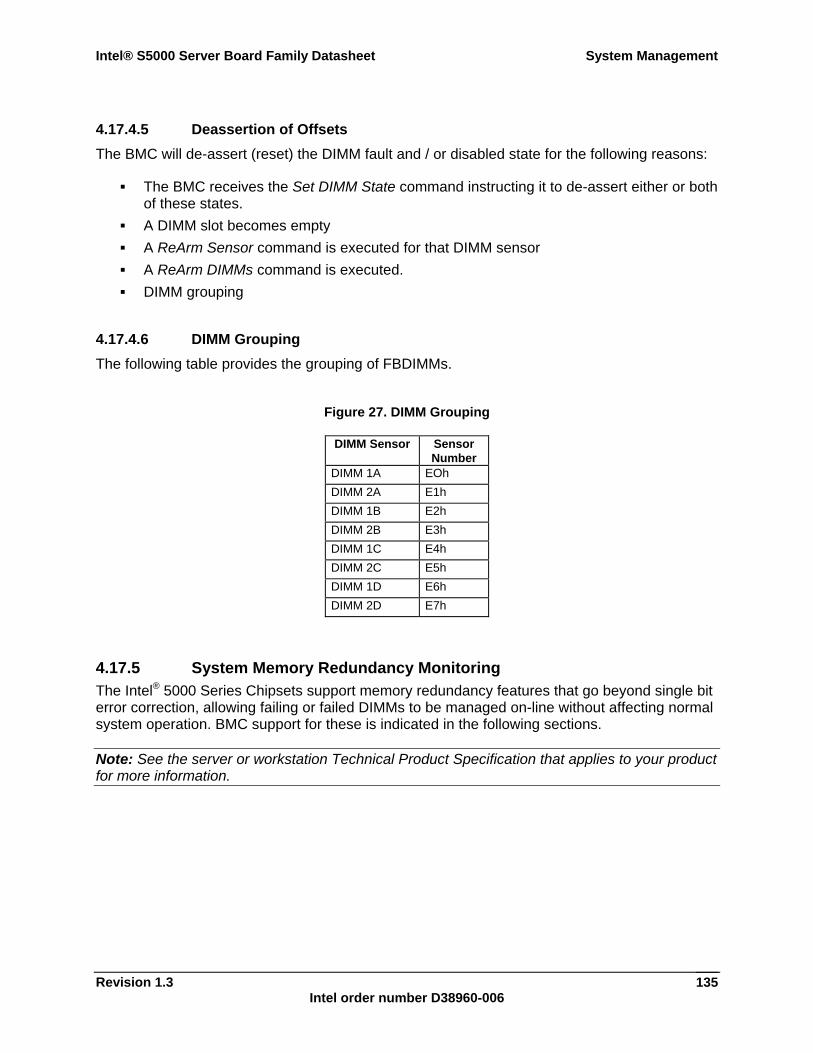
Intel® S5000 Server Board Family Datasheet System Management
Revision 1.3 Intel order number D38960-006
135
4.17.4.5 Deassertion of Offsets The BMC will de-assert (reset) the DIMM fault and / or disabled state for the following reasons:
The BMC receives the Set DIMM State command instructing it to de-assert either or both of these states.
A DIMM slot becomes empty A ReArm Sensor command is executed for that DIMM sensor A ReArm DIMMs command is executed. DIMM grouping
4.17.4.6 DIMM Grouping The following table provides the grouping of FBDIMMs.
Figure 27. DIMM Grouping
DIMM Sensor Sensor Number
DIMM 1A EOh DIMM 2A E1h DIMM 1B E2h DIMM 2B E3h DIMM 1C E4h DIMM 2C E5h DIMM 1D E6h DIMM 2D E7h
4.17.5 System Memory Redundancy Monitoring The Intel® 5000 Series Chipsets support memory redundancy features that go beyond single bit error correction, allowing failing or failed DIMMs to be managed on-line without affecting normal system operation. BMC support for these is indicated in the following sections.
Note: See the server or workstation Technical Product Specification that applies to your product for more information.
System Management Intel® S5000 Server Board Family Datasheet
Revision 1.3 Intel order number D38960-006
136
4.17.5.1 DIMM Sparing With DIMM sparing, the BMC will implement two sensors per DIMM sparing domain (the set of DIMMs which share a spare set of DIMMs). Each sparing domain will have an associated unique Entity ID. Both sensors will belong to that Entity.
DIMM sparing redundancy sensor Sparing redundancy is determined by the BIOS. The BIOS conveys this state to the BMC. The BMC then sets the state of the associated sensor for the specific sparing domain appropriately. This sensor is of type Availability Status (0Bh) and indicates whether the domain is redundant or not (i.e., whether there are spare DIMM(s) available for use). The supported offsets are: - 00h – Fully redundant
Both operational and enabled DIMMs and spares in domain - 01h – Redundancy lost: Sufficient resources, from redundant
Operational and enabled DIMMs in domain and no spares - 05h – Non-redundant: Insufficient resources
No operational or disabled DIMMs in domain
DIMM sparing enabled DIMM sparing is enabled by the BIOS and this configuration is set in the BMC The BMC then sets the state of the associated sensor for the specific sparing domain appropriately. This sensor is used to communicate the enabled state of the sparing feature for the associated domain. The sensor is of type Entity Presence (25h). This state of this sensor indicates whether the DIMM Sparing Redundancy sensor should be ignored. The supported offset is: - 00h – Entity present
If asserted, indicates that the DIMM sparing feature for this domain is enabled and the associated DIMM Sparing Redundancy Sensor state is valid. If not asserted, then the DIMM Sparing Redundancy Sensor should be ignored.
- 01h – Entity absent If asserted, indicates that the DIMM sparing feature for this domain is not available and the associated DIMM Sparing Redundancy Sensor state is invalid. This offset is mutually exclusive with offset 00h - Entity Present.
Note: See the server or workstation Technical Product Specification that applies to your product for more detailed information
4.17.5.2 Memory Mirroring If a specific platform supports memory mirroring, the BMC will implement two sensors per memory mirroring domain (the DIMMs that form a mirrored set). Each mirroring domain will have an associated unique entity ID. Both sensors will belong to that entity.
Intel® S5000 Server Board Family Datasheet System Management
Revision 1.3 Intel order number D38960-006
137
Memory mirroring redundancy sensor Memory mirroring redundancy is determined by the BIOS. The BIOS conveys this state to the BMC. The BMC then sets the state of the associated sensor for the specific mirroring domain appropriately. This sensor is of type Availability Status (0Bh) and indicates whether the domain is redundant or not (i.e., whether all mirrored DIMM(s) are available for use). The supported offsets are: - 00h – Fully redundant
All DIMMs in mirrored domain operational and enabled. - 01h – Redundancy lost : Sufficient resources
One or more failed DIMMs in one of the mirror pairs - 05h – Non-redundant : Insufficient resources
Non-operational DIMMs in both of the mirror pairs Memory mirroring enabled
Memory mirroring is enabled by the BIOS and this configuration is set in the BMC. The BMC then sets the state of the associated sensor for the specific mirroring domain appropriately. This sensor is used to communicate the enabled state of the mirroring feature for the associated domain. The sensor is of type Entity Presence (25h). This state of this sensor indicates whether the Memory Mirroring Redundancy sensor should be ignored. The supported offset is: - 00h – Entity present
If asserted, indicates that the memory mirroring feature for this domain is enabled and the associated memory mirroring redundancy sensor state is valid. If not asserted, then the memory mirroring redundancy sensor should be ignored.
- 01h – Entity absent If asserted, indicates that the memory mirroring feature for this domain is not available and the associated memory mirroring redundancy sensor state is invalid. This offset is mutually exclusive with offset 00h – Entity present.
Note: See the server or workstation Technical Product Specification that applies to your product for more detailed information
System Management Intel® S5000 Server Board Family Datasheet
Revision 1.3 Intel order number D38960-006
138
4.17.6 System Memory Monitoring and System Boot The following sequence of events describes the system booting process with respect to the system memory monitoring feature.
During system boot, BIOS will determine the DIMM population and set this state in the BMC. The BMC initializes the DIMM sensor state based on the discovered presence information and persistent fault information.
BIOS will configure memory, disabling DIMMs as necessary and configure the RAS features as required. The BIOS communicates the set of disabled DIMMs to the BMC and the BIOS then communicates the RAS feature configuration (enabled / disabled features) to the BMC.
The BIOS will then notify BMC to any one of the three redundancy states as defined in section 4.17.5.1.
The BIOS will test the memory. For any memory errors that cause the BIOS to disable a DIMM or generate an error event, the BIOS will notify the BMC of DIMM failure.
The BIOS must enable BMC system memory error monitoring.
4.18 PCI Express* Support
4.18.1 PCI Express Link Sensors The BMC implements a series of sensors of IPMI type Critical Interrupt that are used to log run-time PCI Express link errors detected by the BIOS. An entity ID in the SDR records associates the errors with PCI Express per the IPMI entity ID definitions.
When the BIOS detects an error, it communicates this to the BMC.
If an error state is asserted on one of the PCI Express* sensors, the BMC will set the Front panel fault LED to indicate a degraded condition. The sensor state is deasserted for the following reasons:
The sensor is rearmed through an IPMI command. The system is reset or powered-on.
Deassertion of the sensor state will remove that state as a contribution to the front panel fault LED.
4.18.2 BMC Self-test The BMC performs various tests as part of its initialization. If a failure is determined (e.g., corrupt BMC SDR), the BMC stores the error internally. BMC or BMC sub-system failures detected during regular BMC operation may also be stored internally.
Intel® S5000 Server Board Family Datasheet System Management
Revision 1.3 Intel order number D38960-006
139
4.19 Field Replaceable Unit (FRU) / Fault LED Control Several sets of FRU / POST / fault LEDs are supported. Some LEDs are owned by the BMC and some by the BIOS.
The BMC owns control of the following FRU / fault LEDs:
Fan fault LEDs: There is a fan fault LED associated with each fan. The BMC will light a fan fault LED if the associated fan tach sensor has a lower critical threshold event status asserted. Fan tach sensors are manual rearm sensors, therefore once the lower critical threshold has been crossed, the LED will remain lit until the sensor is rearmed. These sensors are rearmed at system DC power-on and system reset.
CPU fault LEDs: There is a CPU fault LED associated with each processor slot. The BMC will light a CPU fault LED when the associated processor status sensor detects either configuration error or processor disabled. Processor status sensors are manual rearm sensors, therefore once either of these circumstances are detected, the LED will remain lit until the sensor is rearmed. These sensors are NOT rearmed at system DC power-on and system reset.
4.20 Hot-swap Backplane (HSBP) Support The following is a list of BMC – HSC interactions.
BMC initialization agent configures HSC sensors. This occurs when the system is DC powered-on or reset.
Commands may be bridged through the BMC to the HSC via the IPMB. This is typically used by system software to access HSC status or to update the HSC firmware.
The HSBP, including the HSC, does not have power applied when the system is in the power-off (S0 sleep) state. Therefore when the system transitions to the DC power-on state, the HSC must reach an initialized state before communication with the BMC is possible.
4.21 Intel® Remote Management Module (Intel® RMM) Support
The Intel® Remote Management Module (Intel® RMM) provides keyboard, video, mouse (KVM) redirection capability and other advanced functionality. This section describes specific BMC support for the Intel® RMM add-in card.
4.21.1 Discovery Sequence The server board BMC supports a set of commands for setting and retrieving configuration information related to the server board support for the Intel® RMM. These commands are primarily used by the add-in card when power is first applied to the card. They query the BMC to discover platform support for the add-in connector.
The Intel® RMM uses this information to adapt to the specific connector support, to form a complete description of the network connectivity options available, and as the first step in reconfiguring the BMC according to its own configuration requirements.
System Management Intel® S5000 Server Board Family Datasheet
Revision 1.3 Intel order number D38960-006
140
The BMC provides configuration command interfaces when used with an Intel® RMM. This is done through a combination of IPMI and IPMI OEM commands. The BMC does not automatically handle this configuration. It relies on the Intel® RMM to discover the BMC add-in support and then to configure the BMC according to the Intel® RMM requirements. Typically, the Intel® RMM would have been previously configured by a software utility.
4.21.2 Division of Network Traffic Server management network traffic is handled either by the Intel® RMM or by the BMC, depending on the physical configuration. This is described in the two sub-sections below. The BMC only handles IPMI-over-LAN traffic, including SOL traffic, even if no Intel® RMM is installed. The Intel® RMM handles TCP/IP traffic. Other basic protocols are routed depending on the BMC and / or Intel® RMM configuration.
4.21.2.1 Third NIC Channel Interface to Intel® RMM The Intel® RMM supports a dedicated NIC, the Intel® RMM NIC. The Intel® RMM owns routing the network packets received over this interface. IPMI-over-LAN traffic, including SOL traffic, received by the Intel® RMM through this NIC is forwarded to the BMC over an FML or SMBus data link. The Intel® RMM handles other server management traffic autonomously.
The BMC supports this mode of operation through the fast management link (FML) network interface (FNI). This is a high-speed serial interface that provides the data link between the Intel® RMM and the Intel® 631xESB / 632xESB I/O Controller Hub BMC. When the feature is enabled, the BMC treats this data flow as a third LAN-based IPMI channel, in addition to the two Intel® 631xESB / 632xESB I/O Controller Hub-embedded NICs, and any IPMI response data is sent back over the FML bus as necessary. The FNI mode of operation is disabled when the BMC is reset due to a loss of standby power.
The BMC does not require the Intel® RMM to reassemble IP fragments before forwarding them, but it is necessary for the Intel® RMM to do so to identify the UDP or TCP port that is targeted by the IP payload.
4.21.3 Event Forwarding The BMC supports sending notification to the Intel® RMM when certain events occur within the BMC’s domain. This is implemented by the event forwarding mechanism. Event forwarding is a capability that enables the BMC to forward to an add-in controller a copy of event information that it internally generates or receives from a Platform Event message.
The following sub-sections describe BMC behavior when the event forwarding feature is enabled. The formats of the event record data for forwarded events are based on the SEL event records and OEM SEL record formats defined in Tables 32-1 and 32-2 of the IPMI 2.0 Specification.
Intel® S5000 Server Board Family Datasheet System Management
Revision 1.3 Intel order number D38960-006
141
4.21.3.1 SEL Forwarding When BMC SEL events are generated through any mechanism other than the Add SEL Entry command, the BMC will send time-stamped copies of these events to the Intel® RMM). Events are forwarded even if the BMC’s SEL is full.
4.21.3.2 BMC Status Change Forwarding The BMC sends notifications of other status change events that may be of interest to the registered add-in device. The BMC does not require the add-in device to take any action based on the event data.
4.21.4 Serial Routing The BMC provides support for the optional IPMI command, Set Serial Routing Mux, which supports implementations where an add-in card can take over responsibility for serial port sharing from the BMC. The command enables an add-in card or adjunct management controller to direct the BMC to route serial connections to the add-in card or to allow the connections to be handled by the BMC. Logically, this action can be viewed as controlling a hardware multiplexer (serial routing mux) that routes the serial signals between the BMC and the add-in card, although this specification does not describe or require a particular hardware implementation for supporting this capability.
4.21.4.1 Serial Routing and SOL SOL may be supported by either the BMC, using SOL in accordance with the IPMI 2.0 Specification, or by the Intel® RMM using Telnet. For the Intel® RMM-based method, the Intel® RMM must gain control of the serial mux from the BMC.
If the BMC is utilizing its UART interface when the command is received (for instance for BMC-based SOL or EMP) then it will immediately close the session and the serial channel will appear as disabled.
SOL cannot be routed through both the Intel® RMM and the BMC simultaneously.
4.21.5 Messaging Interfaces This section describes the supported BMC communication interfaces:
Host SMS Interface via low pin count (LPC) / (KCS) interface Host SMM Interface via low pin count (LPC) / keyboard controller style (KCS) interface Intelligent platform management bus (IPMB) I2C interface PCI SMBus Emergency management port (EMP) using the IPMI over Serial / Modem protocols for
serial remote access. LAN interface using the IPMI-over-LAN protocols
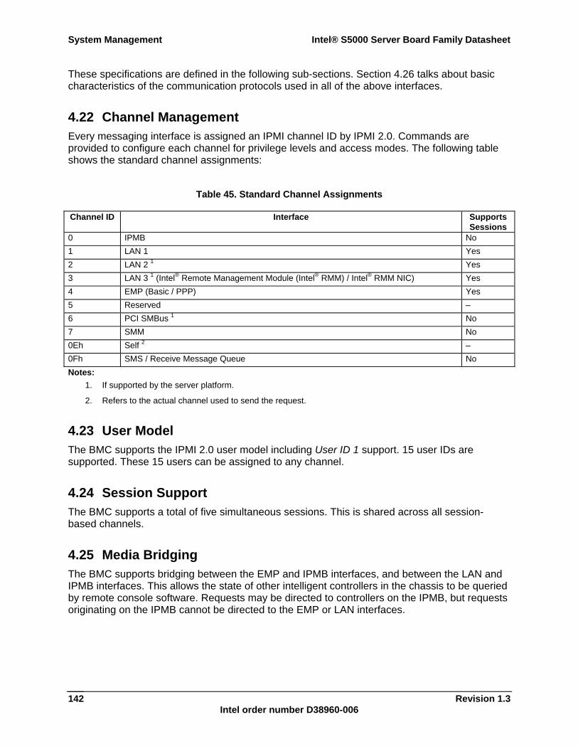
System Management Intel® S5000 Server Board Family Datasheet
Revision 1.3 Intel order number D38960-006
142
These specifications are defined in the following sub-sections. Section 4.26 talks about basic characteristics of the communication protocols used in all of the above interfaces.
4.22 Channel Management Every messaging interface is assigned an IPMI channel ID by IPMI 2.0. Commands are provided to configure each channel for privilege levels and access modes. The following table shows the standard channel assignments:
Table 45. Standard Channel Assignments
Channel ID Interface SupportsSessions
0 IPMB No 1 LAN 1 Yes 2 LAN 2 1 Yes 3 LAN 3 1 (Intel® Remote Management Module (Intel® RMM) / Intel® RMM NIC) Yes 4 EMP (Basic / PPP) Yes 5 Reserved – 6 PCI SMBus 1 No 7 SMM No 0Eh Self 2 – 0Fh SMS / Receive Message Queue No Notes:
1. If supported by the server platform.
2. Refers to the actual channel used to send the request.
4.23 User Model The BMC supports the IPMI 2.0 user model including User ID 1 support. 15 user IDs are supported. These 15 users can be assigned to any channel.
4.24 Session Support The BMC supports a total of five simultaneous sessions. This is shared across all session-based channels.
4.25 Media Bridging The BMC supports bridging between the EMP and IPMB interfaces, and between the LAN and IPMB interfaces. This allows the state of other intelligent controllers in the chassis to be queried by remote console software. Requests may be directed to controllers on the IPMB, but requests originating on the IPMB cannot be directed to the EMP or LAN interfaces.
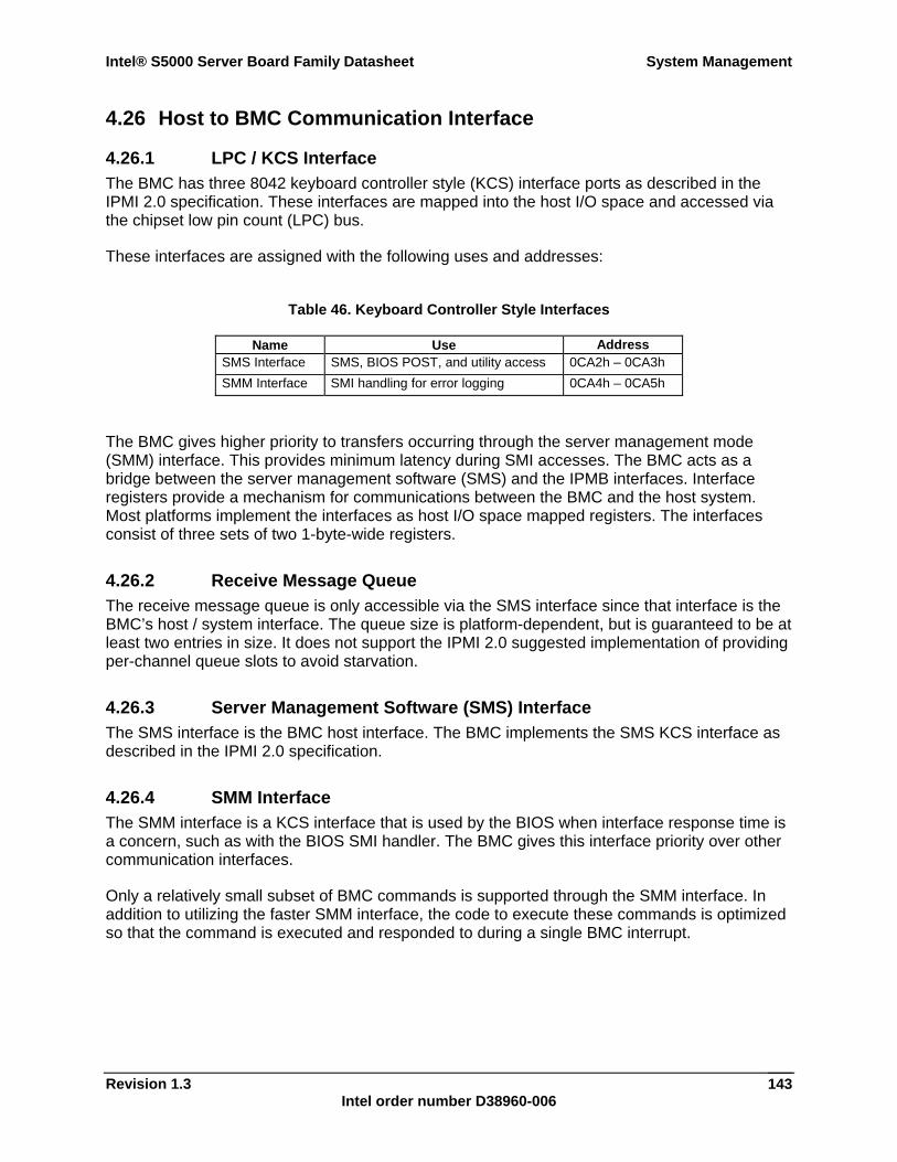
Intel® S5000 Server Board Family Datasheet System Management
Revision 1.3 Intel order number D38960-006
143
4.26 Host to BMC Communication Interface
4.26.1 LPC / KCS Interface The BMC has three 8042 keyboard controller style (KCS) interface ports as described in the IPMI 2.0 specification. These interfaces are mapped into the host I/O space and accessed via the chipset low pin count (LPC) bus.
These interfaces are assigned with the following uses and addresses:
Table 46. Keyboard Controller Style Interfaces
Name Use Address SMS Interface SMS, BIOS POST, and utility access 0CA2h – 0CA3h SMM Interface SMI handling for error logging 0CA4h – 0CA5h
The BMC gives higher priority to transfers occurring through the server management mode (SMM) interface. This provides minimum latency during SMI accesses. The BMC acts as a bridge between the server management software (SMS) and the IPMB interfaces. Interface registers provide a mechanism for communications between the BMC and the host system. Most platforms implement the interfaces as host I/O space mapped registers. The interfaces consist of three sets of two 1-byte-wide registers.
4.26.2 Receive Message Queue The receive message queue is only accessible via the SMS interface since that interface is the BMC’s host / system interface. The queue size is platform-dependent, but is guaranteed to be at least two entries in size. It does not support the IPMI 2.0 suggested implementation of providing per-channel queue slots to avoid starvation.
4.26.3 Server Management Software (SMS) Interface The SMS interface is the BMC host interface. The BMC implements the SMS KCS interface as described in the IPMI 2.0 specification.
4.26.4 SMM Interface The SMM interface is a KCS interface that is used by the BIOS when interface response time is a concern, such as with the BIOS SMI handler. The BMC gives this interface priority over other communication interfaces.
Only a relatively small subset of BMC commands is supported through the SMM interface. In addition to utilizing the faster SMM interface, the code to execute these commands is optimized so that the command is executed and responded to during a single BMC interrupt.
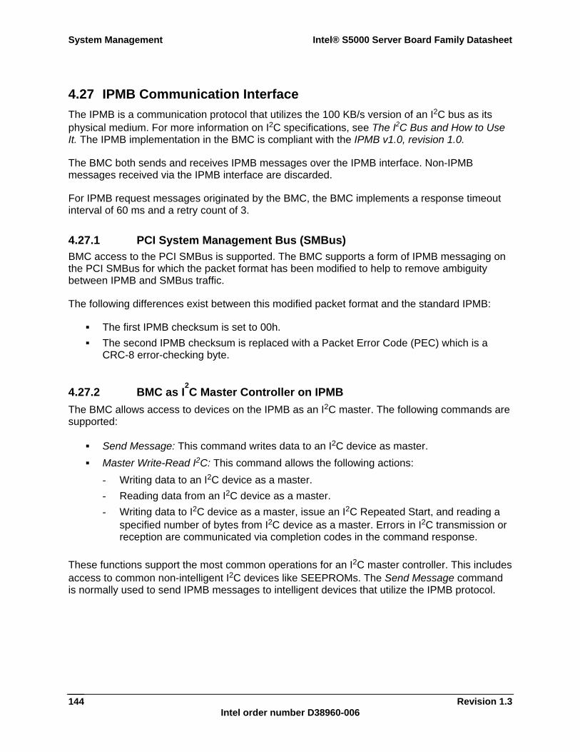
System Management Intel® S5000 Server Board Family Datasheet
Revision 1.3 Intel order number D38960-006
144
4.27 IPMB Communication Interface The IPMB is a communication protocol that utilizes the 100 KB/s version of an I2C bus as its physical medium. For more information on I2C specifications, see The I2C Bus and How to Use It. The IPMB implementation in the BMC is compliant with the IPMB v1.0, revision 1.0.
The BMC both sends and receives IPMB messages over the IPMB interface. Non-IPMB messages received via the IPMB interface are discarded.
For IPMB request messages originated by the BMC, the BMC implements a response timeout interval of 60 ms and a retry count of 3.
4.27.1 PCI System Management Bus (SMBus) BMC access to the PCI SMBus is supported. The BMC supports a form of IPMB messaging on the PCI SMBus for which the packet format has been modified to help to remove ambiguity between IPMB and SMBus traffic.
The following differences exist between this modified packet format and the standard IPMB:
The first IPMB checksum is set to 00h. The second IPMB checksum is replaced with a Packet Error Code (PEC) which is a
CRC-8 error-checking byte.
4.27.2 BMC as I2C Master Controller on IPMB
The BMC allows access to devices on the IPMB as an I2C master. The following commands are supported:
Send Message: This command writes data to an I2C device as master. Master Write-Read I2C: This command allows the following actions:
- Writing data to an I2C device as a master. - Reading data from an I2C device as a master. - Writing data to I2C device as a master, issue an I2C Repeated Start, and reading a
specified number of bytes from I2C device as a master. Errors in I2C transmission or reception are communicated via completion codes in the command response.
These functions support the most common operations for an I2C master controller. This includes access to common non-intelligent I2C devices like SEEPROMs. The Send Message command is normally used to send IPMB messages to intelligent devices that utilize the IPMB protocol.
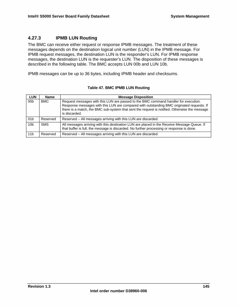
Intel® S5000 Server Board Family Datasheet System Management
Revision 1.3 Intel order number D38960-006
145
4.27.3 IPMB LUN Routing The BMC can receive either request or response IPMB messages. The treatment of these messages depends on the destination logical unit number (LUN) in the IPMB message. For IPMB request messages, the destination LUN is the responder’s LUN. For IPMB response messages, the destination LUN is the requester’s LUN. The disposition of these messages is described in the following table. The BMC accepts LUN 00b and LUN 10b.
IPMB messages can be up to 36 bytes, including IPMB header and checksums.
Table 47. BMC IPMB LUN Routing
LUN Name Message Disposition 00b BMC Request messages with this LUN are passed to the BMC command handler for execution.
Response messages with this LUN are compared with outstanding BMC originated requests. If there is a match, the BMC sub-system that sent the request is notified. Otherwise the message is discarded.
01b Reserved Reserved – All messages arriving with this LUN are discarded. 10b SMS All messages arriving with this destination LUN are placed in the Receive Message Queue. If
that buffer is full, the message is discarded. No further processing or response is done. 11b Reserved Reserved – All messages arriving with this LUN are discarded.
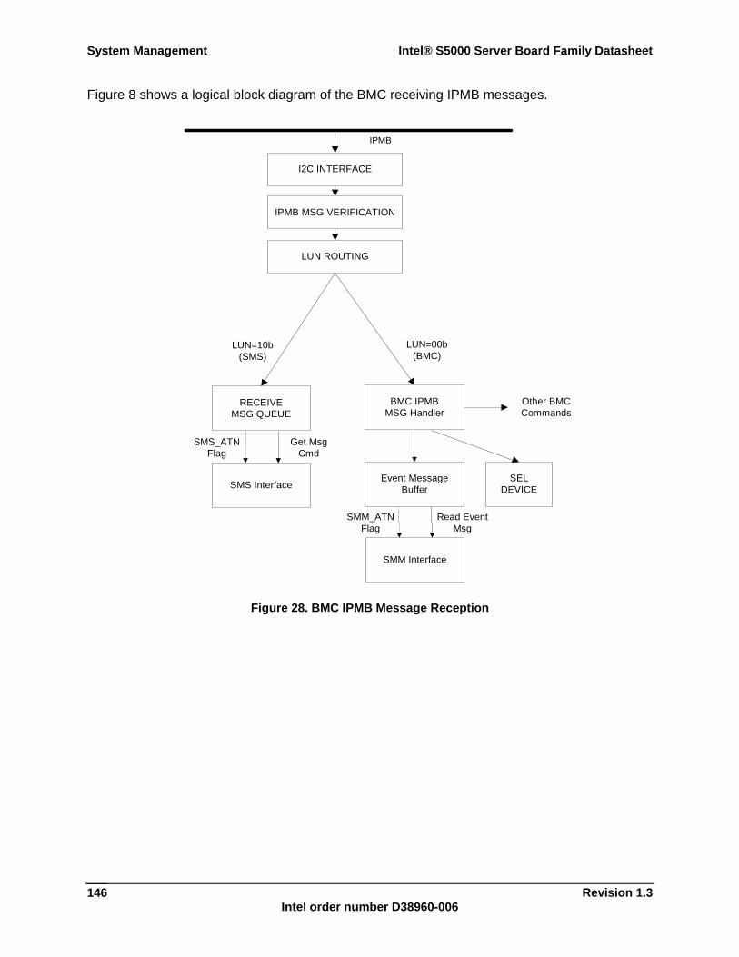
System Management Intel® S5000 Server Board Family Datasheet
Revision 1.3 Intel order number D38960-006
146
Figure 8 shows a logical block diagram of the BMC receiving IPMB messages.
IPMB
LUN ROUTING
IPMB MSG VERIFICATION
I2C INTERFACE
LUN=00b(BMC)
LUN=10b(SMS)
Other BMCCommands
SMM Interface
Event MessageBuffer
SMM_ATNFlag
Read EventMsg
BMC IPMBMSG Handler
SELDEVICESMS Interface
RECEIVEMSG QUEUE
SMS_ATNFlag
Get MsgCmd
Figure 28. BMC IPMB Message Reception
Intel® S5000 Server Board Family Datasheet System Management
Revision 1.3 Intel order number D38960-006
147
4.28 Emergency Management Port (EMP) Interface The EMP interface is the Intel implementation of the IPMI 2.0 IPMI over serial feature. The primary goal of providing an out-of-band RS232 connection is to give system administrators the ability to access low-level server management firmware functions by using commonly available tools. To make it easy to use and to provide high-compatibility with LAN and IPMB protocols, this protocol design adopts some features of both protocols.
The Intel implementation shares the EMP function with the platform’s Serial B interface. The BMC has control over which agent (BMC or system) has access to Serial B port. Hardware handshaking, and the the Ring Indicate and Data Carrier Detect signals are supported.
The basic mode of IPMI over serial is supported and is available whether or not DC power is on. Additional details on the IPMI over serial / modem interface is available in the IPMI 2.0 specification.
4.28.1 COM2 Port Switching As specified in the IPMI 2.0 specification, if EMP is enabled, then the BMC will watch the serial traffic when the COM2 port is owned by the system. This is done to respond to in-band port switching requests. Serial traffic snooping is done in basic mode, although the exact sequences recognized in the two modes is different.
4.28.2 Basic Mode Basic mode uses a protocol in which IPMI requests are transmitted over the serial port with minimum framing, providing a low overhead implementation. Command receipt by the BMC is acknowledged on a per-packet basis.
Basic mode minimumly supports None (un-authenticated) and Straight Password / Key authentication types. Callback is supported in basic mode.
4.28.3 Terminal Mode The BMC supports terminal mode as specified in the IPMI 2.0 specification. Terminal mode provides a printable ASCII text-based mechanism for delivering IPMI messages to the BMC over the serial channel or any packet-based interface. Messages can be delivered in two forms:
Via hex-ASCII pair encoded IPMI commands Via text SYS commands
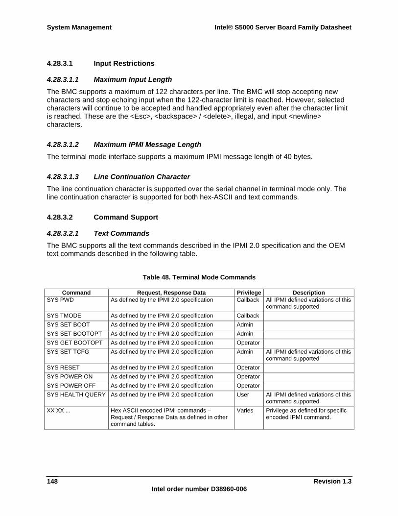
System Management Intel® S5000 Server Board Family Datasheet
Revision 1.3 Intel order number D38960-006
148
4.28.3.1 Input Restrictions
4.28.3.1.1 Maximum Input Length The BMC supports a maximum of 122 characters per line. The BMC will stop accepting new characters and stop echoing input when the 122-character limit is reached. However, selected characters will continue to be accepted and handled appropriately even after the character limit is reached. These are the <Esc>, <backspace> / <delete>, illegal, and input <newline> characters.
4.28.3.1.2 Maximum IPMI Message Length The terminal mode interface supports a maximum IPMI message length of 40 bytes.
4.28.3.1.3 Line Continuation Character The line continuation character is supported over the serial channel in terminal mode only. The line continuation character is supported for both hex-ASCII and text commands.
4.28.3.2 Command Support
4.28.3.2.1 Text Commands The BMC supports all the text commands described in the IPMI 2.0 specification and the OEM text commands described in the following table.
Table 48. Terminal Mode Commands
Command Request, Response Data Privilege Description SYS PWD As defined by the IPMI 2.0 specification Callback All IPMI defined variations of this
command supported SYS TMODE As defined by the IPMI 2.0 specification Callback SYS SET BOOT As defined by the IPMI 2.0 specification Admin SYS SET BOOTOPT As defined by the IPMI 2.0 specification Admin SYS GET BOOTOPT As defined by the IPMI 2.0 specification Operator SYS SET TCFG As defined by the IPMI 2.0 specification Admin All IPMI defined variations of this
command supported SYS RESET As defined by the IPMI 2.0 specification Operator SYS POWER ON As defined by the IPMI 2.0 specification Operator SYS POWER OFF As defined by the IPMI 2.0 specification Operator SYS HEALTH QUERY As defined by the IPMI 2.0 specification User All IPMI defined variations of this
command supported XX XX ... Hex ASCII encoded IPMI commands –
Request / Response Data as defined in other command tables.
Varies Privilege as defined for specific encoded IPMI command.
Intel® S5000 Server Board Family Datasheet System Management
Revision 1.3 Intel order number D38960-006
149
4.28.3.2.2 Text Command Privilege Levels The BMC supports the privilege level scheme for terminal mode text commands as specified in Table 48.
4.28.3.3 Bridging Support The BMC supports the optional bridging functionality described in the IPMI 2.0 specification.
4.28.4 Invalid Password Handling If three successive invalid Activate Session commands are received on the EMP interface, the BMC will send the hang-up sequence if in modem mode and delay 30 seconds before accepting another Activate Session command. The BMC will also log an Out-of-band Access Password Violation event to the system event log each time an invalid Activate Session command is received.
4.28.5 Serial Ping Message Behavior The BMC outputs the IPMI 2.0 specification Serial Connection Active command, or serial ping, over the serial connection once every two seconds when basic mode is enabled in the EMP configuration settings. However, serial ping message behavior can vary depending on the types of operating modes enabled.
4.28.5.1 Operating Mode (Connection Mode Enable) Auto-detection If basic mode and at least one other operating mode are enabled, and the BMC is currently auto-detecting the operating mode, the BMC outputs the serial ping until an operating mode is detected. If the operating mode detected is not basic mode, the serial pings are automatically disabled. Upon connection loss, session loss, or session closure, the serial pings are automatically re-enabled based upon the EMP configuration settings.
4.28.5.2 Terminal Mode If terminal mode is the only operating mode enabled in the EMP configuration settings, the serial ping is automatically disabled, regardless of the EMP configuration settings. If the EMP configuration changes, the serial ping message behavior will automatically be re-evaluated as necessary.
System Management Intel® S5000 Server Board Family Datasheet
Revision 1.3 Intel order number D38960-006
150
4.29 LAN Interface The BMC implements both the IPMI 1.5 and IPMI 2.0 messaging models. These provide out-of-band local area network (LAN) communication between the BMC and the external world.
The BMC supports a maximum of three LAN interfaces:
Two of the LAN interfaces utilize the embedded Intel® 631xESB / 632xESB I/O Controller Hub NICs (one channel per embedded NIC).
One LAN interface utilizes an optional external NIC known as the Intel® RMM NIC. This NIC requires the presence of the optional Intel® Remote Management Module add-in card.
See the IPMI 2.0 specification for details about the IPMI-over-LAN protocol.
4.29.1 IPMI 1.5 Messaging The communication protocol packet format consists of IPMI requests and responses encapsulated in an IPMI session wrapper for authentication, and wrapped in an RMCP packet, which is wrapped in an IP/UDP packet. Although authentication is provided, no encryption is provided, so administrating some settings, such as user passwords, through this interface is not advised.
Session establishment commands are IPMI commands that do not require authentication or an associated session.
The BMC supports None (no authentication), Straight Password / Key and MD5 authentication types over the LAN interface.
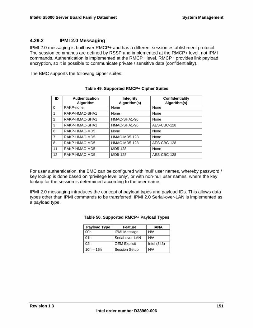
Intel® S5000 Server Board Family Datasheet System Management
Revision 1.3 Intel order number D38960-006
151
4.29.2 IPMI 2.0 Messaging IPMI 2.0 messaging is built over RMCP+ and has a different session establishment protocol. The session commands are defined by RSSP and implemented at the RMCP+ level, not IPMI commands. Authentication is implemented at the RMCP+ level. RMCP+ provides link payload encryption, so it is possible to communicate private / sensitive data (confidentiality).
The BMC supports the following cipher suites:
Table 49. Supported RMCP+ Cipher Suites
ID Authentication Algorithm
Integrity Algorithm(s)
Confidentiality Algorithm(s)
0 RAKP-none None None 1 RAKP-HMAC-SHA1 None None 2 RAKP-HMAC-SHA1 HMAC-SHA1-96 None 3 RAKP-HMAC-SHA1 HMAC-SHA1-96 AES-CBC-128 6 RAKP-HMAC-MD5 None None 7 RAKP-HMAC-MD5 HMAC-MD5-128 None 8 RAKP-HMAC-MD5 HMAC-MD5-128 AES-CBC-128 11 RAKP-HMAC-MD5 MD5-128 None 12 RAKP-HMAC-MD5 MD5-128 AES-CBC-128
For user authentication, the BMC can be configured with ‘null’ user names, whereby password / key lookup is done based on ‘privilege level only’, or with non-null user names, where the key lookup for the session is determined according to the user name.
IPMI 2.0 messaging introduces the concept of payload types and payload IDs. This allows data types other than IPMI commands to be transferred. IPMI 2.0 Serial-over-LAN is implemented as a payload type.
Table 50. Supported RMCP+ Payload Types
Payload Type Feature IANA 00h IPMI Message N/A 01h Serial-over-LAN N/A 02h OEM Explicit Intel (343) 10h – 15h Session Setup N/A
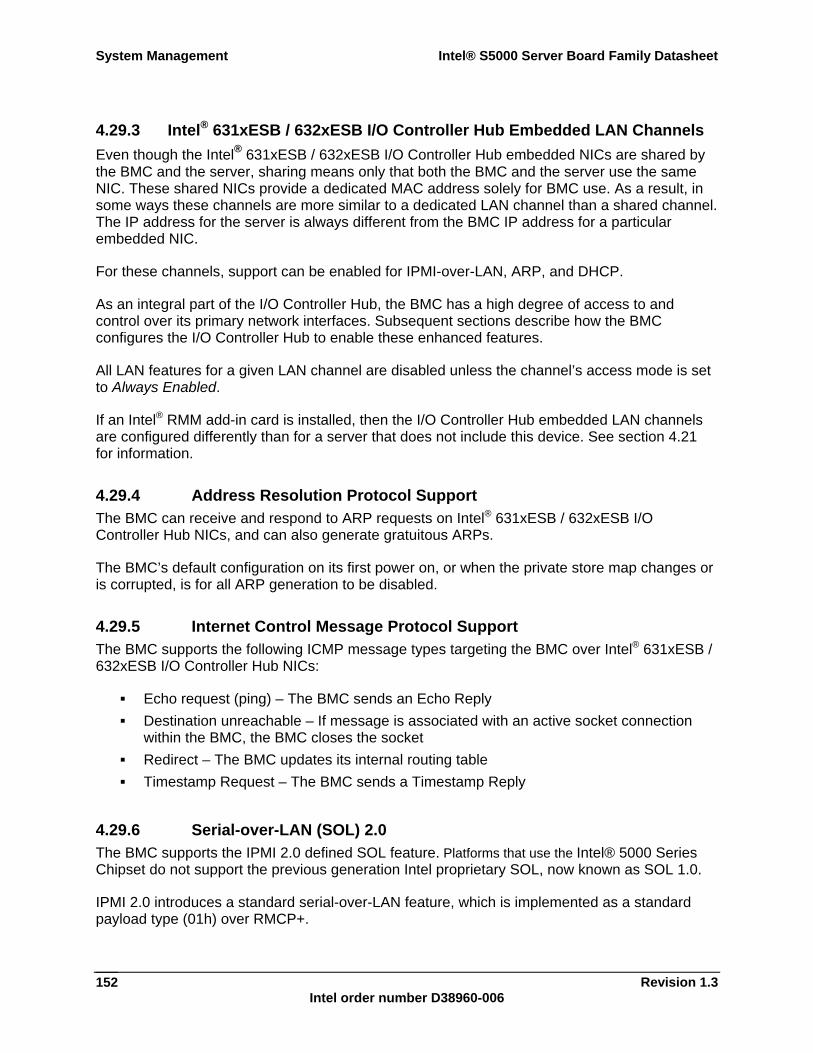
System Management Intel® S5000 Server Board Family Datasheet
Revision 1.3 Intel order number D38960-006
152
4.29.3 Intel® 631xESB / 632xESB I/O Controller Hub Embedded LAN Channels Even though the Intel® 631xESB / 632xESB I/O Controller Hub embedded NICs are shared by the BMC and the server, sharing means only that both the BMC and the server use the same NIC. These shared NICs provide a dedicated MAC address solely for BMC use. As a result, in some ways these channels are more similar to a dedicated LAN channel than a shared channel. The IP address for the server is always different from the BMC IP address for a particular embedded NIC.
For these channels, support can be enabled for IPMI-over-LAN, ARP, and DHCP.
As an integral part of the I/O Controller Hub, the BMC has a high degree of access to and control over its primary network interfaces. Subsequent sections describe how the BMC configures the I/O Controller Hub to enable these enhanced features.
All LAN features for a given LAN channel are disabled unless the channel’s access mode is set to Always Enabled.
If an Intel® RMM add-in card is installed, then the I/O Controller Hub embedded LAN channels are configured differently than for a server that does not include this device. See section 4.21 for information.
4.29.4 Address Resolution Protocol Support The BMC can receive and respond to ARP requests on Intel® 631xESB / 632xESB I/O Controller Hub NICs, and can also generate gratuitous ARPs.
The BMC’s default configuration on its first power on, or when the private store map changes or is corrupted, is for all ARP generation to be disabled.
4.29.5 Internet Control Message Protocol Support The BMC supports the following ICMP message types targeting the BMC over Intel® 631xESB / 632xESB I/O Controller Hub NICs:
Echo request (ping) – The BMC sends an Echo Reply Destination unreachable – If message is associated with an active socket connection
within the BMC, the BMC closes the socket Redirect – The BMC updates its internal routing table Timestamp Request – The BMC sends a Timestamp Reply
4.29.6 Serial-over-LAN (SOL) 2.0 The BMC supports the IPMI 2.0 defined SOL feature. Platforms that use the Intel® 5000 Series Chipset do not support the previous generation Intel proprietary SOL, now known as SOL 1.0.
IPMI 2.0 introduces a standard serial-over-LAN feature, which is implemented as a standard payload type (01h) over RMCP+.
Intel® S5000 Server Board Family Datasheet Error Reporting and Handling
Revision 1.3 Intel order number D38960-006
153
5. Error Reporting and Handling This chapter provides error message, error codes, and beep codes. For information about the role of the BIOS in error handling and the interaction between the BIOS, platform hardware, and server management firmware with regard to error handling see Chapter 4, System Management.
5.1 Fault Resilient Booting (FRB) Fault resilient booting (FRB) is feature that Intel provides to detect and handle errors during the system boot process. FRB helps to make sure the system boots, even if one or more processors fail during POST. There are several possible failures during the booting process that can be detected and handled by the BIOS and BMC:
Boot-strap processor (BSP) POST failure (FRB2 watchdog timer) Operating system load failures Application processor (AP) failures
5.1.1 BSP POST Failures (FRB-2) The FRB-2 process uses a watchdog timer that can be configured to reset the system if it hangs during POST. The BIOS sets the FRB-2 timer to 6 minutes.
The BIOS disables the watchdog timer before prompting the user for a boot password / user password, while scanning for option ROM, and when the user enters BIOS Setup. If the system hangs during POST, before the BIOS disables the FRB-2 timer, the BMC generates an asynchronous system reset (ASR).
The BMC retains status bits that can the BIOS can read later in POST to disable the previously failing processor, to log the appropriate event into the system event log, and to display an appropriate error message.
5.1.2 Operating System Load Failures (OS Boot Timer) The BIOS provides an additional watchdog timer to provide fault resilient booting to the operating system. This timer option is disabled by default. The timeout value and the option to enable the timer are configured in BIOS Setup. When enabled, the BIOS enables the OS Boot Timer in the BMC. It is the responsibility of the operating system or an application to disable this timer once the operating system has successfully loaded.
Warning: Enabling this option without having an operating system or server management application installed that supports this feature will cause the system to reboot when the timer expires. Consult your application or operating system documentation to ensure this feature is supported.
Error Reporting and Handling Intel® S5000 Server Board Family Datasheet
Revision 1.3 Intel order number D38960-006
154
5.2 Error Handling and Logging This section defines how errors are handled by the system BIOS, including a discussion of the role of the BIOS in error handling and the interaction between the BIOS, platform hardware, and server management firmware with regard to error handling. In addition, error-logging techniques are described and beep codes for errors are defined.
5.2.1 Error Sources and Types Server management must correctly and consistently handle system errors. System errors that can be enabled and disabled individually or as a group can be categorized as follows:
PCI bus Memory single- and multi-bit errors Sensors Errors detected during POST and logged as POST errors
Sensors are managed by the BMC. The BMC is capable of receiving event messages from individual sensors and logging system events.
5.2.2 Error Logging via SMI Handler The SMI handler handles and logs system-level events that are not visible to server management firmware. The SMI handler pre-processes all system errors, even those that are normally considered to generate an NMI.
The SMI handler sends a command to the BMC to log the event and provides the data to be logged. For example, the BIOS programs the hardware to generate an SMI on a single-bit memory error and logs the location of the failed FBDIMM in the system event log. System events that are handled by the BIOS generate SMIs. After the BIOS finishes logging the error it will assert the NMI if needed.
5.2.2.1 PCI Bus Error The PCI bus defines two error pins, PERR# and SERR#. These are used for reporting PCI parity errors and system errors, respectively. The BIOS can be instructed to enable or disable reporting PERR# and SERR# through NMI. Disabling NMI for PERR# and / or SERR# also disables logging of the corresponding event.
In the case of PERR#, the PCI bus master has the option to retry the offending transaction, or to report it using SERR#. All other PCI-related errors are reported by SERR#. All PCI-to-PCI bridges are configured so that they generate SERR# on the primary interface whenever there is SERR# on the secondary side, as long as SERR# is enabled in BIOS Setup. The same is true for PERR#.
5.2.2.2 PCI Express* Errors Fatal and critical PCI Express* errors are logged as PCI system errors and promoted to an NMI. All non-critical PCI Express errors are logged as PCI parity errors.
Intel® S5000 Server Board Family Datasheet Error Reporting and Handling
Revision 1.3 Intel order number D38960-006
155
5.2.2.3 Processor Bus Error The BIOS enables the error correction and detection capabilities of the processors by setting appropriate bits in the processor model specific register (MSR) and the appropriate bits in the chipset.
In the case of unrecoverable errors on the host processor bus, proper execution of the SMI handler cannot be guaranteed and the handler cannot be relied upon to log such conditions. The handler records the error to the system event log only if the system has not experienced a catastrophic failure that compromises the integrity of the handler.
5.2.2.4 Memory Bus Error The hardware is programmed to generate an SMI on correctable data errors in the memory array. The SMI handler records the error and the FBDIMM location to the system event log. Uncorrectable errors in the memory array are mapped to SMI because the BMC cannot determine the location of the faulty FBDIMM. The uncorrectable errors may have corrupted the contents of SMRAM. The SMI handler will log the failing FBDIMM number to the BMC if the SMRAM contents are still valid. The ability to isolate the failure down to a single FBDIMM may not be available on certain errors, and / or during early POST.
5.2.2.5 OS Watchdog Failure If an operating system device driver is using the watchdog timer to detect software or hardware failures and that timer expires, an asynchronous reset (ASR) is generated. This is equivalent to a hard reset. The POST portion of the BIOS can query the BMC for watchdog reset events as the system reboots, and logs this event in the SEL.
5.2.2.6 Boot Event The BIOS downloads the system date and time to the BMC during POST and logs a boot event. Software that parses the event log should not treat the boot event as an error.
5.2.3 Timestamp Clock Event The BMC maintains a 4-byte internal timestamp clock used by the SEL and SDR subsystems. The timestamp clock is incremented once per second.
5.2.3.1 No Real-time Clock (RTC) Access After a BMC reset, the BMC sets the initial value of the timestamp clock to 0x00000000, after which it is incremented once per second. A SEL event containing a timestamp from 0x00000000 to 0x14000000 has a timestamp value that is relative to BMC initialization.
During POST, the BIOS tells the BMC the current RTC time. The BMC maintains that time using a hardware signal driven from the same oscillator that maintains the system’s time-of-day clock. If the user changes the RTC during operation, SMS is responsible for synchronizing the time with the BMC.
Note: The BMC can lose the current timestamp during a BMC cold reset or a firmware update.
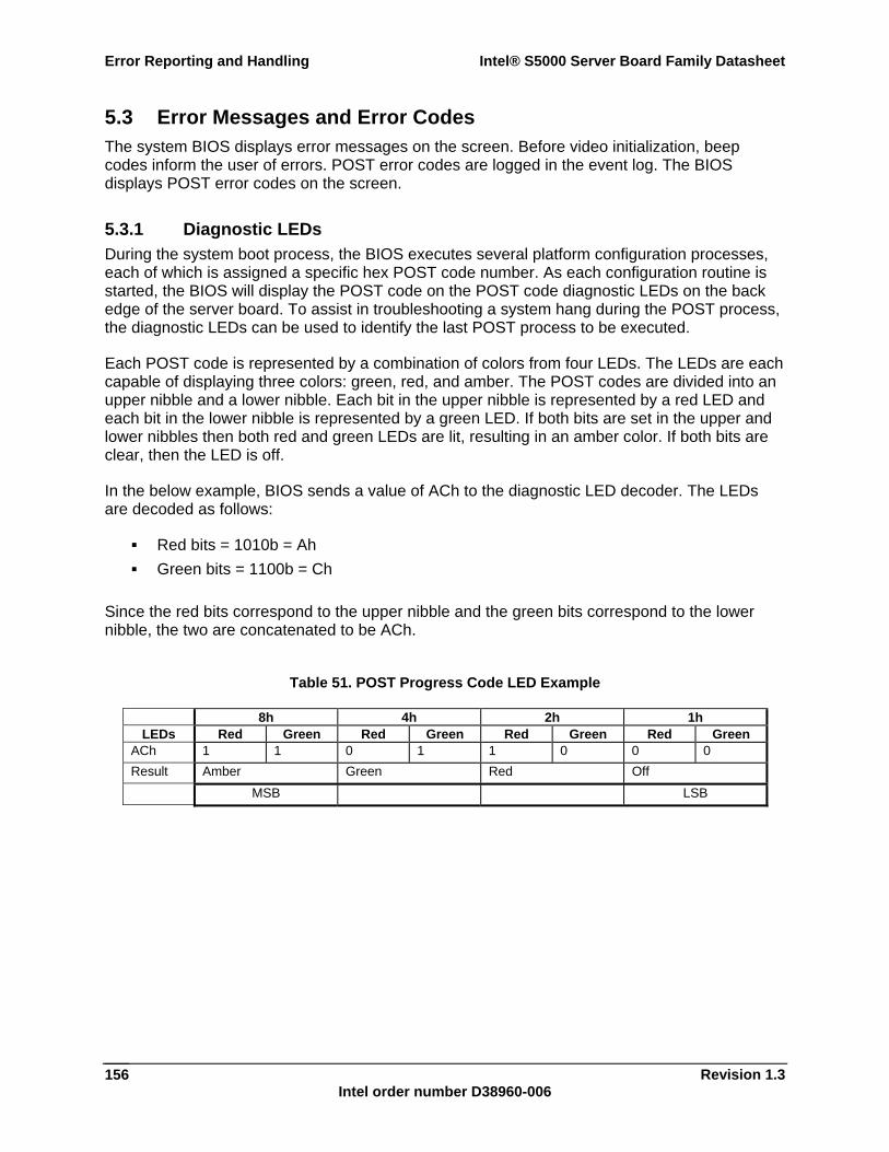
Error Reporting and Handling Intel® S5000 Server Board Family Datasheet
Revision 1.3 Intel order number D38960-006
156
5.3 Error Messages and Error Codes The system BIOS displays error messages on the screen. Before video initialization, beep codes inform the user of errors. POST error codes are logged in the event log. The BIOS displays POST error codes on the screen.
5.3.1 Diagnostic LEDs During the system boot process, the BIOS executes several platform configuration processes, each of which is assigned a specific hex POST code number. As each configuration routine is started, the BIOS will display the POST code on the POST code diagnostic LEDs on the back edge of the server board. To assist in troubleshooting a system hang during the POST process, the diagnostic LEDs can be used to identify the last POST process to be executed.
Each POST code is represented by a combination of colors from four LEDs. The LEDs are each capable of displaying three colors: green, red, and amber. The POST codes are divided into an upper nibble and a lower nibble. Each bit in the upper nibble is represented by a red LED and each bit in the lower nibble is represented by a green LED. If both bits are set in the upper and lower nibbles then both red and green LEDs are lit, resulting in an amber color. If both bits are clear, then the LED is off.
In the below example, BIOS sends a value of ACh to the diagnostic LED decoder. The LEDs are decoded as follows:
Red bits = 1010b = Ah Green bits = 1100b = Ch
Since the red bits correspond to the upper nibble and the green bits correspond to the lower nibble, the two are concatenated to be ACh.
Table 51. POST Progress Code LED Example
8h 4h 2h 1h LEDs Red Green Red Green Red Green Red Green
ACh 1 1 0 1 1 0 0 0 Result Amber Green Red Off
MSB LSB
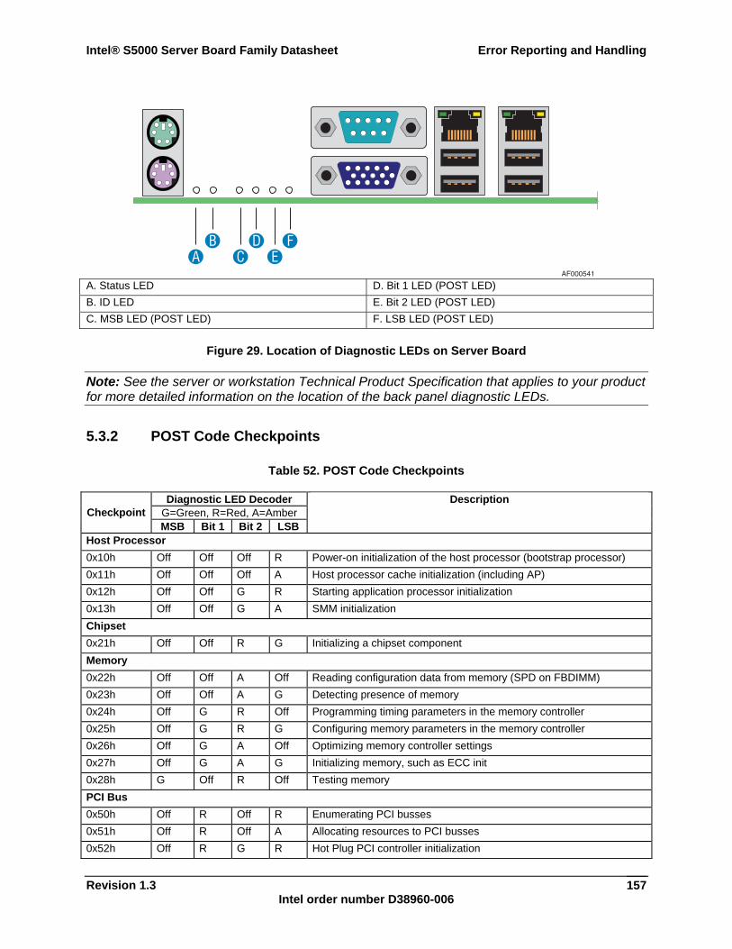
Intel® S5000 Server Board Family Datasheet Error Reporting and Handling
Revision 1.3 Intel order number D38960-006
157
A. Status LED D. Bit 1 LED (POST LED) B. ID LED E. Bit 2 LED (POST LED) C. MSB LED (POST LED) F. LSB LED (POST LED)
Figure 29. Location of Diagnostic LEDs on Server Board
Note: See the server or workstation Technical Product Specification that applies to your product for more detailed information on the location of the back panel diagnostic LEDs.
5.3.2 POST Code Checkpoints
Table 52. POST Code Checkpoints
Diagnostic LED Decoder G=Green, R=Red, A=Amber Checkpoint MSB Bit 1 Bit 2 LSB
Description
Host Processor 0x10h Off Off Off R Power-on initialization of the host processor (bootstrap processor) 0x11h Off Off Off A Host processor cache initialization (including AP) 0x12h Off Off G R Starting application processor initialization 0x13h Off Off G A SMM initialization Chipset 0x21h Off Off R G Initializing a chipset component Memory 0x22h Off Off A Off Reading configuration data from memory (SPD on FBDIMM) 0x23h Off Off A G Detecting presence of memory 0x24h Off G R Off Programming timing parameters in the memory controller 0x25h Off G R G Configuring memory parameters in the memory controller 0x26h Off G A Off Optimizing memory controller settings 0x27h Off G A G Initializing memory, such as ECC init 0x28h G Off R Off Testing memory PCI Bus 0x50h Off R Off R Enumerating PCI busses 0x51h Off R Off A Allocating resources to PCI busses 0x52h Off R G R Hot Plug PCI controller initialization
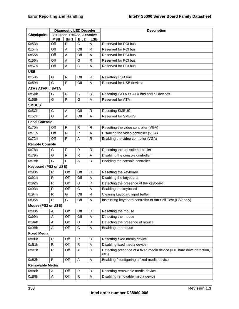
Error Reporting and Handling Intel® S5000 Server Board Family Datasheet
Revision 1.3 Intel order number D38960-006
158
Diagnostic LED Decoder G=Green, R=Red, A=Amber Checkpoint MSB Bit 1 Bit 2 LSB
Description
0x53h Off R G A Reserved for PCI bus 0x54h Off A Off R Reserved for PCI bus 0x55h Off A Off A Reserved for PCI bus 0x56h Off A G R Reserved for PCI bus 0x57h Off A G A Reserved for PCI bus USB 0x58h G R Off R Resetting USB bus 0x59h G R Off A Reserved for USB devices ATA / ATAPI / SATA 0x5Ah G R G R Resetting PATA / SATA bus and all devices 0x5Bh G R G A Reserved for ATA SMBUS 0x5Ch G A Off R Resetting SMBUS 0x5Dh G A Off A Reserved for SMBUS Local Console 0x70h Off R R R Resetting the video controller (VGA) 0x71h Off R R A Disabling the video controller (VGA) 0x72h Off R A R Enabling the video controller (VGA) Remote Console 0x78h G R R R Resetting the console controller 0x79h G R R A Disabling the console controller 0x7Ah G R A R Enabling the console controller Keyboard (PS2 or USB) 0x90h R Off Off R Resetting the keyboard 0x91h R Off Off A Disabling the keyboard 0x92h R Off G R Detecting the presence of the keyboard 0x93h R Off G A Enabling the keyboard 0x94h R G Off R Clearing keyboard input buffer 0x95h R G Off A Instructing keyboard controller to run Self Test (PS2 only) Mouse (PS2 or USB) 0x98h A Off Off R Resetting the mouse 0x99h A Off Off A Detecting the mouse 0x9Ah A Off G R Detecting the presence of mouse 0x9Bh A Off G A Enabling the mouse Fixed Media 0xB0h R Off R R Resetting fixed media device 0xB1h R Off R A Disabling fixed media device 0xB2h R Off A R Detecting presence of a fixed media device (IDE hard drive detection,
etc.) 0xB3h R Off A A Enabling / configuring a fixed media device Removable Media 0xB8h A Off R R Resetting removable media device 0xB9h A Off R A Disabling removable media device
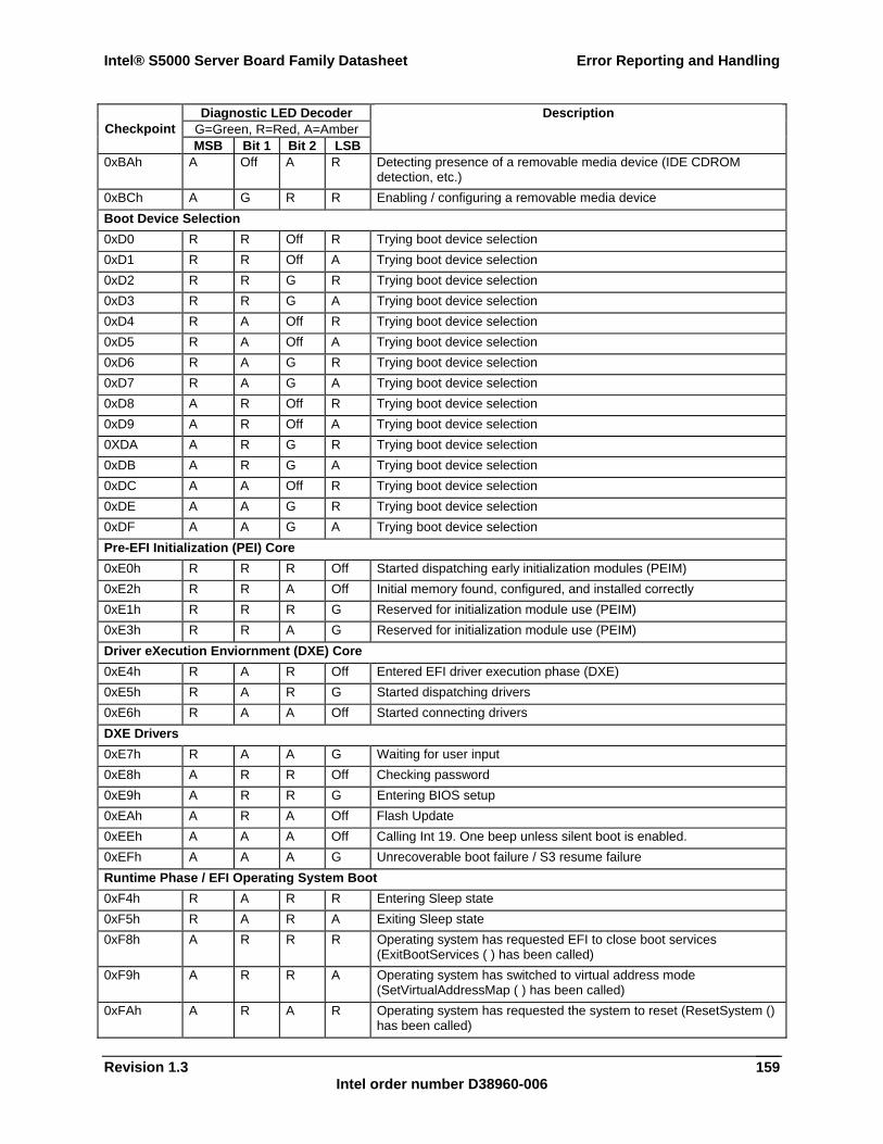
Intel® S5000 Server Board Family Datasheet Error Reporting and Handling
Revision 1.3 Intel order number D38960-006
159
Diagnostic LED Decoder G=Green, R=Red, A=Amber Checkpoint MSB Bit 1 Bit 2 LSB
Description
0xBAh A Off A R Detecting presence of a removable media device (IDE CDROM detection, etc.)
0xBCh A G R R Enabling / configuring a removable media device Boot Device Selection 0xD0 R R Off R Trying boot device selection 0xD1 R R Off A Trying boot device selection 0xD2 R R G R Trying boot device selection 0xD3 R R G A Trying boot device selection 0xD4 R A Off R Trying boot device selection 0xD5 R A Off A Trying boot device selection 0xD6 R A G R Trying boot device selection 0xD7 R A G A Trying boot device selection 0xD8 A R Off R Trying boot device selection 0xD9 A R Off A Trying boot device selection 0XDA A R G R Trying boot device selection 0xDB A R G A Trying boot device selection 0xDC A A Off R Trying boot device selection 0xDE A A G R Trying boot device selection 0xDF A A G A Trying boot device selection Pre-EFI Initialization (PEI) Core 0xE0h R R R Off Started dispatching early initialization modules (PEIM) 0xE2h R R A Off Initial memory found, configured, and installed correctly 0xE1h R R R G Reserved for initialization module use (PEIM) 0xE3h R R A G Reserved for initialization module use (PEIM) Driver eXecution Enviornment (DXE) Core 0xE4h R A R Off Entered EFI driver execution phase (DXE) 0xE5h R A R G Started dispatching drivers 0xE6h R A A Off Started connecting drivers DXE Drivers 0xE7h R A A G Waiting for user input 0xE8h A R R Off Checking password 0xE9h A R R G Entering BIOS setup 0xEAh A R A Off Flash Update 0xEEh A A A Off Calling Int 19. One beep unless silent boot is enabled. 0xEFh A A A G Unrecoverable boot failure / S3 resume failure Runtime Phase / EFI Operating System Boot 0xF4h R A R R Entering Sleep state 0xF5h R A R A Exiting Sleep state 0xF8h A R R R Operating system has requested EFI to close boot services
(ExitBootServices ( ) has been called) 0xF9h A R R A Operating system has switched to virtual address mode
(SetVirtualAddressMap ( ) has been called) 0xFAh A R A R Operating system has requested the system to reset (ResetSystem ()
has been called)
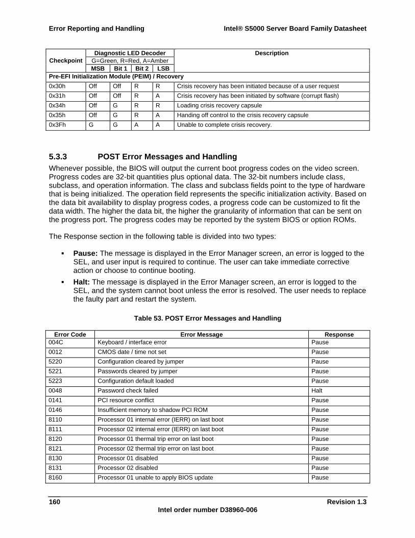
Error Reporting and Handling Intel® S5000 Server Board Family Datasheet
Revision 1.3 Intel order number D38960-006
160
Diagnostic LED Decoder G=Green, R=Red, A=Amber Checkpoint MSB Bit 1 Bit 2 LSB
Description
Pre-EFI Initialization Module (PEIM) / Recovery 0x30h Off Off R R Crisis recovery has been initiated because of a user request 0x31h Off Off R A Crisis recovery has been initiated by software (corrupt flash) 0x34h Off G R R Loading crisis recovery capsule 0x35h Off G R A Handing off control to the crisis recovery capsule 0x3Fh G G A A Unable to complete crisis recovery.
5.3.3 POST Error Messages and Handling Whenever possible, the BIOS will output the current boot progress codes on the video screen. Progress codes are 32-bit quantities plus optional data. The 32-bit numbers include class, subclass, and operation information. The class and subclass fields point to the type of hardware that is being initialized. The operation field represents the specific initialization activity. Based on the data bit availability to display progress codes, a progress code can be customized to fit the data width. The higher the data bit, the higher the granularity of information that can be sent on the progress port. The progress codes may be reported by the system BIOS or option ROMs.
The Response section in the following table is divided into two types:
Pause: The message is displayed in the Error Manager screen, an error is logged to the SEL, and user input is required to continue. The user can take immediate corrective action or choose to continue booting.
Halt: The message is displayed in the Error Manager screen, an error is logged to the SEL, and the system cannot boot unless the error is resolved. The user needs to replace the faulty part and restart the system.
Table 53. POST Error Messages and Handling
Error Code Error Message Response 004C Keyboard / interface error Pause 0012 CMOS date / time not set Pause 5220 Configuration cleared by jumper Pause 5221 Passwords cleared by jumper Pause 5223 Configuration default loaded Pause 0048 Password check failed Halt 0141 PCI resource conflict Pause 0146 Insufficient memory to shadow PCI ROM Pause 8110 Processor 01 internal error (IERR) on last boot Pause 8111 Processor 02 internal error (IERR) on last boot Pause 8120 Processor 01 thermal trip error on last boot Pause 8121 Processor 02 thermal trip error on last boot Pause 8130 Processor 01 disabled Pause 8131 Processor 02 disabled Pause 8160 Processor 01 unable to apply BIOS update Pause
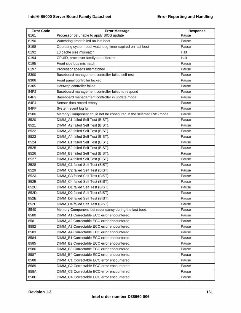
Intel® S5000 Server Board Family Datasheet Error Reporting and Handling
Revision 1.3 Intel order number D38960-006
161
Error Code Error Message Response 8161 Processor 02 unable to apply BIOS update Pause 8190 Watchdog timer failed on last boot Pause 8198 Operating system boot watchdog timer expired on last boot Pause 0192 L3 cache size mismatch Halt 0194 CPUID, processor family are different Halt 0195 Front side bus mismatch Pause 0197 Processor speeds mismatched Pause 8300 Baseboard management controller failed self-test Pause 8306 Front panel controller locked Pause 8305 Hotswap controller failed Pause 84F2 Baseboard management controller failed to respond Pause 84F3 Baseboard management controller in update mode Pause 84F4 Sensor data record empty Pause 84FF System event log full Pause 8500 Memory Component could not be configured in the selected RAS mode. Pause 8520 DIMM_A1 failed Self Test (BIST). Pause 8521 DIMM_A2 failed Self Test (BIST). Pause 8522 DIMM_A3 failed Self Test (BIST). Pause 8523 DIMM_A4 failed Self Test (BIST). Pause 8524 DIMM_B1 failed Self Test (BIST). Pause 8525 DIMM_B2 failed Self Test (BIST). Pause 8526 DIMM_B3 failed Self Test (BIST). Pause 8527 DIMM_B4 failed Self Test (BIST). Pause 8528 DIMM_C1 failed Self Test (BIST). Pause 8529 DIMM_C2 failed Self Test (BIST). Pause 852A DIMM_C3 failed Self Test (BIST). Pause 852B DIMM_C4 failed Self Test (BIST). Pause 852C DIMM_D1 failed Self Test (BIST). Pause 852D DIMM_D2 failed Self Test (BIST). Pause 852E DIMM_D3 failed Self Test (BIST). Pause 852F DIMM_D4 failed Self Test (BIST). Pause 8540 Memory Component lost redundancy during the last boot. Pause 8580 DIMM_A1 Correctable ECC error encountered. Pause 8581 DIMM_A2 Correctable ECC error encountered. Pause 8582 DIMM_A3 Correctable ECC error encountered. Pause 8583 DIMM_A4 Correctable ECC error encountered. Pause 8584 DIMM_B1 Correctable ECC error encountered. Pause 8585 DIMM_B2 Correctable ECC error encountered. Pause 8586 DIMM_B3 Correctable ECC error encountered. Pause 8587 DIMM_B4 Correctable ECC error encountered. Pause 8588 DIMM_C1 Correctable ECC error encountered. Pause 8589 DIMM_C2 Correctable ECC error encountered. Pause 858A DIMM_C3 Correctable ECC error encountered. Pause 858B DIMM_C4 Correctable ECC error encountered. Pause
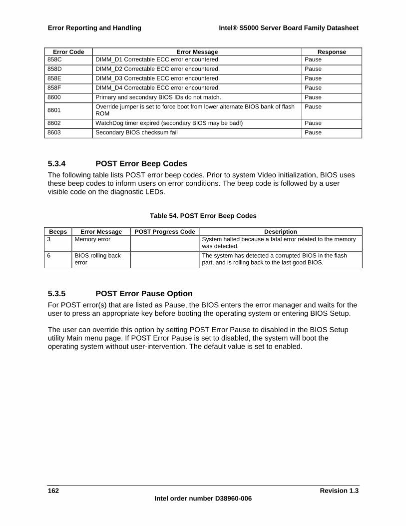
Error Reporting and Handling Intel® S5000 Server Board Family Datasheet
Revision 1.3 Intel order number D38960-006
162
Error Code Error Message Response 858C DIMM_D1 Correctable ECC error encountered. Pause 858D DIMM_D2 Correctable ECC error encountered. Pause 858E DIMM_D3 Correctable ECC error encountered. Pause 858F DIMM_D4 Correctable ECC error encountered. Pause 8600 Primary and secondary BIOS IDs do not match. Pause
8601 Override jumper is set to force boot from lower alternate BIOS bank of flash ROM
Pause
8602 WatchDog timer expired (secondary BIOS may be bad!) Pause 8603 Secondary BIOS checksum fail Pause
5.3.4 POST Error Beep Codes The following table lists POST error beep codes. Prior to system Video initialization, BIOS uses these beep codes to inform users on error conditions. The beep code is followed by a user visible code on the diagnostic LEDs.
Table 54. POST Error Beep Codes
Beeps Error Message POST Progress Code Description 3 Memory error System halted because a fatal error related to the memory
was detected. 6 BIOS rolling back
error The system has detected a corrupted BIOS in the flash
part, and is rolling back to the last good BIOS.
5.3.5 POST Error Pause Option For POST error(s) that are listed as Pause, the BIOS enters the error manager and waits for the user to press an appropriate key before booting the operating system or entering BIOS Setup.
The user can override this option by setting POST Error Pause to disabled in the BIOS Setup utility Main menu page. If POST Error Pause is set to disabled, the system will boot the operating system without user-intervention. The default value is set to enabled.
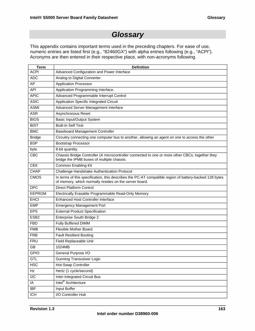
Intel® S5000 Server Board Family Datasheet Glossary
Revision 1.3 Intel order number D38960-006
163
Glossary This appendix contains important terms used in the preceding chapters. For ease of use, numeric entries are listed first (e.g., “82460GX”) with alpha entries following (e.g., “ACPI”). Acronyms are then entered in their respective place, with non-acronyms following.
Term Definition ACPI Advanced Configuration and Power Interface ADC Analog to Digital Converter. AP Application Processor API Application Programming Interface. APIC Advanced Programmable Interrupt Control ASIC Application Specific Integrated Circuit ASMI Advanced Server Management Interface ASR Asynchronous Reset BIOS Basic Input/Output System BIST Built-In Self Test BMC Baseboard Management Controller Bridge Circuitry connecting one computer bus to another, allowing an agent on one to access the other BSP Bootstrap Processor byte 8-bit quantity. CBC Chassis Bridge Controller (A microcontroller connected to one or more other CBCs, together they
bridge the IPMB buses of multiple chassis. CEK Common Enabling Kit CHAP Challenge Handshake Authentication Protocol CMOS In terms of this specification, this describes the PC-AT compatible region of battery-backed 128 bytes
of memory, which normally resides on the server board. DPC Direct Platform Control EEPROM Electrically Erasable Programmable Read-Only Memory EHCI Enhanced Host Controller Interface EMP Emergency Management Port EPS External Product Specification ESB2 Enterprise South Bridge 2 FBD Fully Buffered DIMM FMB Flexible Mother Board FRB Fault Resilient Booting FRU Field Replaceable Unit GB 1024MB GPIO General Purpose I/O GTL Gunning Transceiver Logic HSC Hot-Swap Controller Hz Hertz (1 cycle/second) I2C Inter-Integrated Circuit Bus IA Intel® Architecture IBF Input Buffer ICH I/O Controller Hub
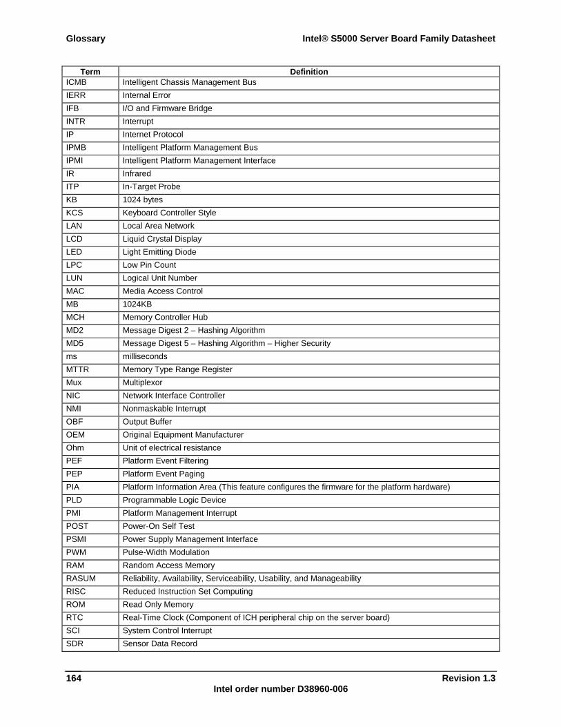
Glossary Intel® S5000 Server Board Family Datasheet
Revision 1.3 Intel order number D38960-006
164
Term Definition ICMB Intelligent Chassis Management Bus IERR Internal Error IFB I/O and Firmware Bridge INTR Interrupt IP Internet Protocol IPMB Intelligent Platform Management Bus IPMI Intelligent Platform Management Interface IR Infrared ITP In-Target Probe KB 1024 bytes KCS Keyboard Controller Style LAN Local Area Network LCD Liquid Crystal Display LED Light Emitting Diode LPC Low Pin Count LUN Logical Unit Number MAC Media Access Control MB 1024KB MCH Memory Controller Hub MD2 Message Digest 2 – Hashing Algorithm MD5 Message Digest 5 – Hashing Algorithm – Higher Security ms milliseconds MTTR Memory Type Range Register Mux Multiplexor NIC Network Interface Controller NMI Nonmaskable Interrupt OBF Output Buffer OEM Original Equipment Manufacturer Ohm Unit of electrical resistance PEF Platform Event Filtering PEP Platform Event Paging PIA Platform Information Area (This feature configures the firmware for the platform hardware) PLD Programmable Logic Device PMI Platform Management Interrupt POST Power-On Self Test PSMI Power Supply Management Interface PWM Pulse-Width Modulation RAM Random Access Memory RASUM Reliability, Availability, Serviceability, Usability, and Manageability RISC Reduced Instruction Set Computing ROM Read Only Memory RTC Real-Time Clock (Component of ICH peripheral chip on the server board) SCI System Control Interrupt SDR Sensor Data Record
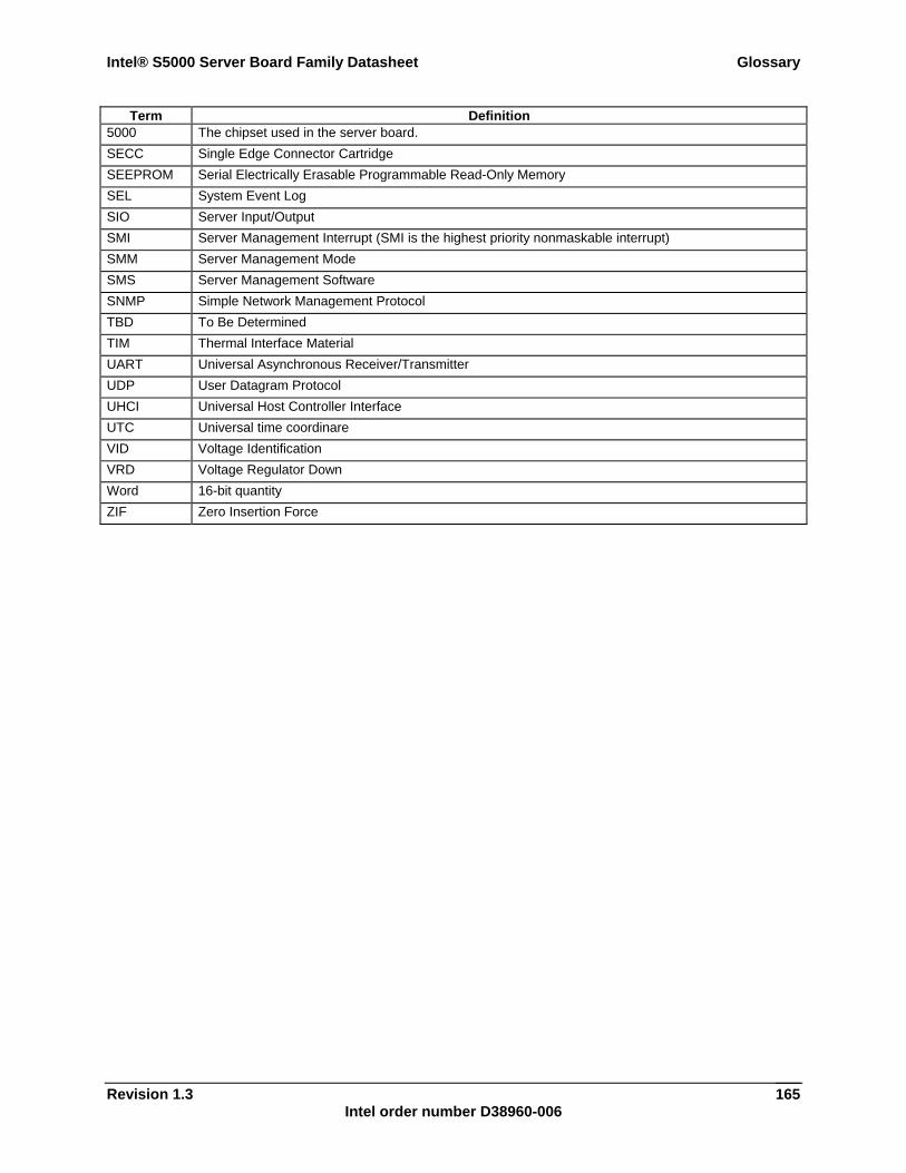
Intel® S5000 Server Board Family Datasheet Glossary
Revision 1.3 Intel order number D38960-006
165
Term Definition 5000 The chipset used in the server board. SECC Single Edge Connector Cartridge SEEPROM Serial Electrically Erasable Programmable Read-Only Memory SEL System Event Log SIO Server Input/Output SMI Server Management Interrupt (SMI is the highest priority nonmaskable interrupt) SMM Server Management Mode SMS Server Management Software SNMP Simple Network Management Protocol TBD To Be Determined TIM Thermal Interface Material UART Universal Asynchronous Receiver/Transmitter UDP User Datagram Protocol UHCI Universal Host Controller Interface UTC Universal time coordinare VID Voltage Identification VRD Voltage Regulator Down Word 16-bit quantity ZIF Zero Insertion Force
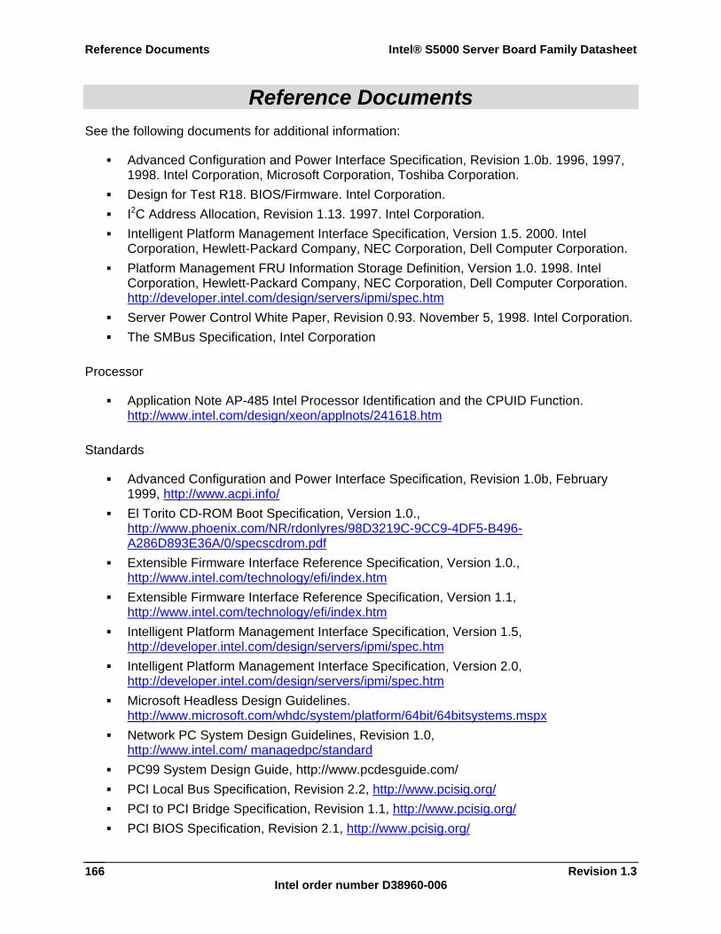
Reference Documents Intel® S5000 Server Board Family Datasheet
Revision 1.3 Intel order number D38960-006
166
Reference Documents See the following documents for additional information:
Advanced Configuration and Power Interface Specification, Revision 1.0b. 1996, 1997, 1998. Intel Corporation, Microsoft Corporation, Toshiba Corporation.
Design for Test R18. BIOS/Firmware. Intel Corporation. I2C Address Allocation, Revision 1.13. 1997. Intel Corporation. Intelligent Platform Management Interface Specification, Version 1.5. 2000. Intel
Corporation, Hewlett-Packard Company, NEC Corporation, Dell Computer Corporation. Platform Management FRU Information Storage Definition, Version 1.0. 1998. Intel
Corporation, Hewlett-Packard Company, NEC Corporation, Dell Computer Corporation. http://developer.intel.com/design/servers/ipmi/spec.htm
Server Power Control White Paper, Revision 0.93. November 5, 1998. Intel Corporation. The SMBus Specification, Intel Corporation
Processor
Application Note AP-485 Intel Processor Identification and the CPUID Function. http://www.intel.com/design/xeon/applnots/241618.htm
Standards
Advanced Configuration and Power Interface Specification, Revision 1.0b, February 1999, http://www.acpi.info/
El Torito CD-ROM Boot Specification, Version 1.0., http://www.phoenix.com/NR/rdonlyres/98D3219C-9CC9-4DF5-B496-A286D893E36A/0/specscdrom.pdf
Extensible Firmware Interface Reference Specification, Version 1.0., http://www.intel.com/technology/efi/index.htm
Extensible Firmware Interface Reference Specification, Version 1.1, http://www.intel.com/technology/efi/index.htm
Intelligent Platform Management Interface Specification, Version 1.5, http://developer.intel.com/design/servers/ipmi/spec.htm
Intelligent Platform Management Interface Specification, Version 2.0, http://developer.intel.com/design/servers/ipmi/spec.htm
Microsoft Headless Design Guidelines. http://www.microsoft.com/whdc/system/platform/64bit/64bitsystems.mspx
Network PC System Design Guidelines, Revision 1.0, http://www.intel.com/ managedpc/standard
PC99 System Design Guide, http://www.pcdesguide.com/ PCI Local Bus Specification, Revision 2.2, http://www.pcisig.org/ PCI to PCI Bridge Specification, Revision 1.1, http://www.pcisig.org/ PCI BIOS Specification, Revision 2.1, http://www.pcisig.org/
Intel® S5000 Server Board Family Datasheet Reference Documents
Revision 1.3 Intel order number D38960-006
167
PCI Power Management Specification, Revision 1.0, http://www.pcisig.org/ PCI IRQ Routing Table Specification, Revision 1.0, Microsoft Corporation. POST Memory Manager Specification, Revision 1.01,
http://www.phoenix.com/NR/rdonlyres/873A00CF-33AC-4775-B77E-08E7B9754993/0/specspmm101.pdf
Plug and Play BIOS Specification, Revision 1.0a, http://www.microsoft.com/whdc/system/pnppwr/pnp/default.mspx
System Management BIOS Reference Specification, Version 2.4, http://www.dmtf.org/standards/published_documents/DSP0134.pdf
Extensible Firmware Interface Specification 1.10 http://www.intel.com/technology/efi/main_specification.htm
Universal Serial Bus Revision 1.1 Specification, http://www.intel.com/technology/usb/spec.htm
Wired For Management Baseline Specification, Revision 2.0, http://www.intel.com/design/archives/wfm/downloads/base20.htm