Intel FPGA SDK for OpenCL€¦ · Intel® FPGA SDK for OpenCL ™ Intel® Arria® 10 GX FPGA...
65
Transcript of Intel FPGA SDK for OpenCL€¦ · Intel® FPGA SDK for OpenCL ™ Intel® Arria® 10 GX FPGA...

Intel® FPGA SDK for OpenCL™
Intel® Arria® 10 GX FPGA Development Kit Reference PlatformPorting Guide
Updated for Intel® Quartus® Prime Design Suite: 17.1
SubscribeSend Feedback
UG-OCL010 | 2017.11.06Latest document on the web: PDF | HTML

Contents
1 Intel® FPGA SDK for OpenCL™ Intel Arria 10 GX FPGA Development Kit ReferencePlatform Porting Guide.............................................................................................. 41.1 Intel Arria 10 GX FPGA Development Kit Reference Platform: Prerequisites.....................41.2 Features of the Intel Arria 10 GX FPGA Development Kit Reference Platform................... 5
1.2.1 Intel Arria 10 GX FPGA Development Kit Reference Platform Board Variants........61.3 Contents of the Intel Arria 10 GX FPGA Development Kit Reference Platform.................. 61.4 Changes in Intel Arria 10 Development Kit Reference Platform from 17.0 to 17.1 ........... 9
2 Developing Your Intel Arria 10 Custom Platform .......................................................... 112.1 Initializing Your Intel Arria 10 Custom Platform......................................................... 112.2 Modifying the Intel Arria 10 GX FPGA Development Kit Reference Platform Design......... 122.3 Integrating Your Intel Arria 10 Custom Platform with the Intel FPGA SDK for OpenCL.....132.4 Setting up the Intel Arria 10 Custom Platform Software Development Environment........142.5 Establishing Intel Arria 10 Custom Platform Host Communication................................ 152.6 Branding Your Intel Arria 10 Custom Platform........................................................... 152.7 Changing the Device Part Number...........................................................................162.8 Connecting the Memory in the Intel Arria 10 Custom Platform.....................................172.9 Modifying the Kernel PLL Reference Clock.................................................................182.10 Integrating an OpenCL Kernel in Your Intel Arria 10 Custom Platform......................... 182.11 Guaranteeing Timing Closure in the Intel Arria 10 Custom Platform............................19
2.11.1 Generating the base.qar Post-Fit Netlist for Your Intel Arria 10 CustomPlatform................................................................................................. 20
2.12 Troubleshooting Intel Arria 10 GX FPGA Development Kit Reference PlatformPorting Issues ..................................................................................................20
3 Intel Arria 10 GX FPGA Development Kit Reference Platform Design Architecture......... 223.1 Host-to-Intel Arria 10 FPGA Communication over PCIe .............................................. 22
3.1.1 Instantiation of Intel Arria 10 PCIe Hard IP with Direct Memory Access.............223.1.2 Device Identification Registers for Intel Arria 10 PCIe Hard IP......................... 243.1.3 Instantiation of the version_id Component................................................... 263.1.4 Definitions of Intel Arria 10 FPGA Development Kit Reference Platform
Hardware Constraints in Software Headers Files........................................... 263.1.5 PCIe Kernel Driver for the Intel Arria 10 GX FPGA Development Kit
Reference Platform...................................................................................273.1.6 Direct Memory Access............................................................................... 283.1.7 Message Signaled Interrupt........................................................................303.1.8 Partial Reconfiguration...............................................................................313.1.9 Cable Autodetect...................................................................................... 323.1.10 Host Channel..........................................................................................33
3.2 DDR4 as Global Memory for OpenCL Applications...................................................... 343.2.1 DDR4 IP Instantiation................................................................................353.2.2 DDR4 Connection to PCIe Host................................................................... 353.2.3 DDR4 Connection to the OpenCL Kernel....................................................... 36
3.3 Host Connection to OpenCL Kernels.........................................................................363.4 Intel Arria 10 FPGA System Design..........................................................................36
3.4.1 Clocks..................................................................................................... 363.4.2 Resets.....................................................................................................373.4.3 Floorplan................................................................................................. 38
Contents
Intel® FPGA SDK for OpenCL™ Intel® Arria® 10 GX FPGA Development Kit Reference Platform Porting Guide2

3.4.4 Global Routing..........................................................................................413.4.5 Pipelining.................................................................................................423.4.6 DDR4 Calibration...................................................................................... 423.4.7 Kernel Reprogramming via Partial Reconfiguration......................................... 42
3.5 Dynamic PLL Reconfiguration..................................................................................433.6 Guaranteed Timing Closure of the Intel Arria 10 GX FPGA Development Kit
Reference Platform Design..................................................................................433.6.1 Supply the Kernel Clock............................................................................. 433.6.2 Guarantee Kernel Clock Timing................................................................... 443.6.3 Provide a Timing-Closed Post-Fit Netlist....................................................... 45
3.7 Intel Quartus Prime Compilation Flow and Scripts......................................................463.7.1 Enabling the Intel Quartus Prime Forward-Compatibility Flow..........................473.7.2 Intel Quartus Prime Compilation Flow for Board Developers ........................... 483.7.3 Intel Quartus Prime Compilation Flow for Custom Platform Users.....................493.7.4 Platform Designer System Generation..........................................................503.7.5 QDB File Generation.................................................................................. 503.7.6 Hash Checking..........................................................................................50
3.8 Addition of Timing Constraints................................................................................ 513.9 Connection of the Intel Arria 10 GX FPGA Development Kit Reference Platform to
the Intel FPGA SDK for OpenCL...........................................................................513.9.1 Describe the Intel Arria 10 GX FPGA Development Kit Reference Platform
to the Intel FPGA SDK for OpenCL.............................................................. 513.9.2 Describe the Intel Arria 10 GX FPGA Development Kit Reference Platform
Hardware to the Intel FPGA SDK for OpenCL................................................523.10 Intel Arria 10 FPGA Programming Flow...................................................................53
3.10.1 Define the Contents of the fpga.bin File for the Intel Arria 10 GX FPGADevelopment Kit Reference Platform...........................................................54
3.11 Host-to-Device MMD Software Implementation........................................................543.12 Implementation of Intel FPGA SDK for OpenCL Utilities............................................ 55
3.12.1 aocl install..............................................................................................553.12.2 aocl uninstall.......................................................................................... 563.12.3 aocl program.......................................................................................... 563.12.4 aocl flash............................................................................................... 563.12.5 aocl diagnose......................................................................................... 573.12.6 aocl list-devices...................................................................................... 58
3.13 Intel Arria 10 FPGA Development Kit Reference Platform Scripts................................583.14 Considerations in Intel Arria 10 GX FPGA Development Kit Reference Platform
Implementation................................................................................................ 59
4 Document Revision History............................................................................................ 60
Contents
Intel® FPGA SDK for OpenCL™ Intel® Arria® 10 GX FPGA Development Kit Reference Platform Porting Guide3

1 Intel® FPGA SDK for OpenCL™ Intel Arria 10 GX FPGADevelopment Kit Reference Platform Porting Guide
The Intel® Arria® 10 GX FPGA Development Kit Reference Platform Porting Guidedescribes the procedures and design considerations for modifying the Intel Arria 10 GXFPGA Development Kit Reference Platform (a10_ref) into your own Custom Platformfor use with the Intel FPGA Software Development Kit (SDK) for OpenCL™ (1) (2).
1.1 Intel Arria 10 GX FPGA Development Kit Reference Platform:Prerequisites
The Intel Arria 10 GX FPGA Development Kit Reference Platform Porting Guideassumes that you are an experienced FPGA designer who is familiar with Intel's FPGAdesign tools and concepts.
Prerequisites for the altera_a10pciedk Reference Platform:
• An Intel Arria 10-based accelerator card with working PCI Express* (PCIe*) andmemory interfaces
Test these interfaces together in the same design using the same version of theIntel Quartus® Prime Pro Edition software that you will use to develop yourCustom Platform.
Attention: The native Arria 10 GX FPGA Development Kit does not automaticallywork with the SDK. Before using the Arria 10 GX FPGA DevelopmentKit with the SDK, you must first contact your field applicationsengineer or regional support center representative who will configurethe development kit for you.
Alternatively, contact support for assistance.
• Intel Quartus Prime Pro Edition software
• Designing with Logic Lock regions
General prerequisites:
• FPGA architecture, including clocking, global routing, and I/Os
• High-speed design
• Timing analysis
• Platform Designer design and Avalon® interfaces
(1) OpenCL and the OpenCL logo are trademarks of Apple Inc. used by permission of the KhronosGroup™.
(2) The Intel FPGA SDK for OpenCL is based on a published Khronos Specification, and has passedthe Khronos Conformance Testing Process. Current conformance status can be found at www.khronos.org/conformance.
UG-OCL010 | 2017.11.06
Intel Corporation. All rights reserved. Intel, the Intel logo, Altera, Arria, Cyclone, Enpirion, MAX, Nios, Quartusand Stratix words and logos are trademarks of Intel Corporation or its subsidiaries in the U.S. and/or othercountries. Intel warrants performance of its FPGA and semiconductor products to current specifications inaccordance with Intel's standard warranty, but reserves the right to make changes to any products and servicesat any time without notice. Intel assumes no responsibility or liability arising out of the application or use of anyinformation, product, or service described herein except as expressly agreed to in writing by Intel. Intelcustomers are advised to obtain the latest version of device specifications before relying on any publishedinformation and before placing orders for products or services.*Other names and brands may be claimed as the property of others.
ISO9001:2008Registered

• Tcl scripting
• PCIe
• DDR4 external memory
This document also assumes that you are familiar with the following Intel FPGA SDKfor OpenCL-specific tools and documentation:
• Custom Platform Toolkit and the Intel FPGA SDK for OpenCL Custom PlatformToolkit User Guide
• Stratix® V Network Reference Platform (s5_net) and the Stratix V NetworkReference Platform Porting Guide
The memory-mapped device (MMD) and driver software stack in the a10_refReference Platform is derived from the s5_net Reference Platform design.
Related Links
• Intel FPGA SDK for OpenCL Custom Platform Toolkit User Guide
• Intel FPGA SDK for OpenCL Intel Arria 10 SoC Development Kit Reference PlatformPorting Guide
• Intel FPGA SDK for OpenCL Cyclone V SoC Development Kit Reference PlatformPorting Guide
• Intel FPGA SDK for OpenCL Stratix V Network Reference Platform Porting Guide
1.2 Features of the Intel Arria 10 GX FPGA Development KitReference Platform
Prior to designing an Intel FPGA SDK for OpenCL Custom Platform, decide on designconsiderations that allow you to fully utilize the available hardware on your computingcard.
The Intel Arria 10 GX FPGA Development Kit Reference Platform targets a subset ofthe hardware features available in the Intel Arria 10 GX FPGA Development Kit.
Figure 1. Hardware Features of the Intel Arria 10 GX FPGA Development Kit
1 Intel® FPGA SDK for OpenCL™ Intel Arria 10 GX FPGA Development Kit Reference PlatformPorting Guide
UG-OCL010 | 2017.11.06
Intel® FPGA SDK for OpenCL™ Intel® Arria® 10 GX FPGA Development Kit Reference Platform Porting Guide5

Features of the a10_ref Reference Platform:
• OpenCL Host
The a10_ref Reference Platform uses a PCIe-based host that connects to the IntelArria 10 PCIe Gen3 x8 hard IP core.
• OpenCL Global Memory
The hardware provides one 2-gigabyte (GB) DDR4 SDRAM daughtercard that ismounted on the HiLo connector (J14 in Figure 1 on page 5).
• FPGA Programming via one of the following methods:
— Partial Reconfiguration (PR) over PCIe.
— External cable and the Intel Arria 10 GX FPGA Development Kit's on-boardIntel FPGA Download Cable II interface.
— External Intel FPGA Download Cable II interface connected to a 10-pin JTAGheader.
• Guaranteed Timing
The a10_ref Reference Platform relies on the Intel Quartus Prime Pro Editioncompilation flow to provide guaranteed timing closure. The timing-clean a10_refReference Platform is preserved in the form of a precompiled post-fit netlist (thatis, the base.qdb Intel Quartus Prime Database Export File). The Intel FPGA SDKfor OpenCL Offline Compiler imports this preserved post-fit netlist into eachOpenCL kernel compilation.
• OpenCL Host Pipe
Using direct memory access (DMA) in Intel Arria 10 PCIe Gen3 x8 hard IP corea10gx_hostch board variant has a direct host to kernel and kernel to host pipe.
1.2.1 Intel Arria 10 GX FPGA Development Kit Reference Platform BoardVariants
The Intel Arria 10 GX FPGA Development Kit Reference Platform has two boardvariants (that is, a10gx and a10gx_hostch) that targets the Intel Arria 10 GX FPGADevelopment Kit containing the production silicon for Intel Arria 10 FPGA (-1 speedgrade) and DDR4-2400 SDRAM .
To compile your OpenCL kernel for a specific board variant, include the -board=<board_name> option in your aoc command (for example, aoc -board=a10gx myKernel.cl).
Related Links
Compiling a Kernel for a Specific FPGA Board (-board=<board_name>)
1.3 Contents of the Intel Arria 10 GX FPGA Development KitReference Platform
Familiarize yourself with the directories and files within the Intel Arria 10 GX FPGADevelopment Kit Reference Platform because they are referenced throughout thisdocument.
1 Intel® FPGA SDK for OpenCL™ Intel Arria 10 GX FPGA Development Kit Reference PlatformPorting Guide
UG-OCL010 | 2017.11.06
Intel® FPGA SDK for OpenCL™ Intel® Arria® 10 GX FPGA Development Kit Reference Platform Porting Guide6

Table 1. Highlights of the Intel Arria 10 GX FPGA Development Kit Reference PlatformDirectory
Windows File or Folder Linux File or Directory Description
board_env.xml board_env.xml eXtensible Markup Language (XML) file that describes theReference Platform to the Intel FPGA SDK for OpenCL.
hardware hardware Contains the Intel Quartus Prime project templates for thea10gx board variant.See Table 2 on page 7 for a list of files in this directory.
windows64 linux64 Contains the MMD library, kernel mode driver, and executablefiles of the SDK utilities (that is, install, uninstall, flash,program, diagnose) for your 64-bit operating system.
source source For Windows, the source folder contains source codes for theMMD library and SDK utilities. The MMD library and the SDKutilities are in the windows64 folder.For Linux, the source directory contains source codes for theMMD library and SDK utilities. The MMD library and the SDKutilities are in the linux64 directory.
Table 2. Contents of the a10gx DirectoryThe following table lists the files in the INTELFPGAOCLSDKROOT/board/a10_ref/hardware/a10gxdirectory, where INTELFPGAOCLSDKROOT points to the location of the SDK installation.
File Description
mem.qsys Platform Designer system that, together with the .ip files in theip/mem subdirectory, implements the mem component.
ddr4.qsys Platform Designer system that, together with the .ip files in the ip/ddr4 subdirectory, implements the ddr4 component.
base.qsf Intel Quartus Prime Settings File for the base project revision. This fileincludes, by reference, all the settings in the flat.qsf file.Use this revision when porting the a10_ref Reference Platform to yourown Custom Platform. The Intel Quartus Prime Pro Edition softwarecompiles this base project revision from source code.
base.qar Intel Quartus Prime Archive File that contains base.qdb, pr_base.id,and base.sdc. This file is generated by the scripts/post_flow_pr.tcl file during base revision compile, and is usedduring import revision compilation.
base.qdb Intel Quartus Prime Database Export File the containsthe precompiled netlist of the static regions of thedesign.
pr_base.id Text file containing a unique number for a given basecompilation that the runtime uses to determine whetherit is safe to use PR programming.
base.sdc Synopsys Design Constraints File that the Intel QuartusPrime software autogenerates during a basecompilation. The base.sdc file is used in the toprevision compilation to import all the timing constraintsfrom the static region.
board.qsys Platform Designer system that implements the board interfaces (that is,the static region) of the OpenCL hardware system.
board_spec.xml XML file that provides the definition of the board hardware interfaces tothe SDK.
continued...
1 Intel® FPGA SDK for OpenCL™ Intel Arria 10 GX FPGA Development Kit Reference PlatformPorting Guide
UG-OCL010 | 2017.11.06
Intel® FPGA SDK for OpenCL™ Intel® Arria® 10 GX FPGA Development Kit Reference Platform Porting Guide7

File Description
device.tcl Tcl file that is included in all revisions and contains all device-specificinformation (for example, device family, ordering part number (OPN),voltage settings, etc.)
flat.qsf Intel Quartus Prime Settings File for the flat project revision. This fileincludes all the common settings, such as pin location assignments, thatare used in the other revisions of the project (that is, base, top, andtop_synth). The base.qsf, top.qsf, and top_synth.qsf filesinclude, by reference, all the settings in the flat.qsf file.The Intel Quartus Prime software compiles the flat revision with minimallocation constraints. The flat revision compilation does not generate abase.qar file that you can use for future import compilations and doesnot implement the guaranteed timing flow.
import_compile.tcl Tcl script for the SDK-user compilation flow (that is, import revisioncompilation).
max5_150.pof Programming file for the MAX® V device on the Intel Arria 10 GX FPGADevelopment Kit that sets the memory reference clock to 150 MHz bydefault at power-up.You must program the max5_150.pof file onto your a10gx board.
opencl_bsp_ip.qsf Intel Quartus Prime Settings File that collects all the required .ip filesin a unique location.During flat and base revision compilations, the board.qsys, mem.qsysand ddr4.qsys Platform Designer files are added to theopencl_bsp_ip.qsf file.
quartus.ini Contains any special Intel Quartus Prime software options that you needto compile OpenCL kernels for the a10_ref Reference Platform.
top.qpf Intel Quartus Prime Project File for the OpenCL hardware system.
top.qsf Intel Quartus Prime Settings File for the SDK-user compilation flow.
top.sdc Synopsys Design Constraints File that contains board-specific timingconstraints.
top.v Top-level Verilog Design File for the OpenCL hardware system.
top_post.sdc Platform Designer and Intel FPGA SDK for OpenCL IP-specific timingconstraints.
top_synth.qsf Intel Quartus Prime Settings File for the Intel Quartus Prime revision inwhich the OpenCL kernel system is synthesized.
ip/mem/<file_name> Directory containing the .ip files that the Intel Quartus Prime ProEdition software needs to parameterize the mem component.You must provide both the mem.qsys file and the corresponding .ipfiles in this directory to the Intel Quartus Prime Pro Edition software.
ip/ddr4/<file_name> Directory containing the .ip files that the Intel Quartus Prime ProEdition software needs to parameterize the ddr4 component.You must provide both the ddr4.qsys file and the corresponding .ipfiles in this directory to the Intel Quartus Prime Pro Edition software.
ip/board/<file_name> Directory containing the .ip files that the Intel Quartus Prime ProEdition software needs to parameterize the board instance.You must provide both the board.qsys file and the corresponding .ipfiles in this directory to the Intel Quartus Prime Pro Edition software.
ip/freeze_wrapper.v Verilog Design File that implements the freeze logic placed at outputs ofthe Partial Reconfiguration region.
ip/irq_controller/<file_name> IP that receives interrupts from the OpenCL kernel system and sendsmessage signaled interrupts (MSI) to the host.
continued...
1 Intel® FPGA SDK for OpenCL™ Intel Arria 10 GX FPGA Development Kit Reference PlatformPorting Guide
UG-OCL010 | 2017.11.06
Intel® FPGA SDK for OpenCL™ Intel® Arria® 10 GX FPGA Development Kit Reference Platform Porting Guide8

File Description
Refer to the Message Signaled Interrupts section for more information.
ip/host_channel IP that implements the DMA descriptor controller as well as AVMM-to-AVST and AVST-to-AVMM between DMA and kernel.Attention: This IP is available only in the a10gx_hostch board variant.
scripts/base_write_sdc.tcl Tcl script that the base revision compilation uses to generate thebase.sdc file containing all the constraints collected in the baserevision compilation. The Intel Quartus Prime Pro Edition software usesthe base.sdc file when compiling the import (top) revision.
scripts/create_fpga_bin_pr.tcl Tcl script that generates the fpga.bin file. The fpga.bin file containsall the necessary files for configuring the FPGA.For more information on the fpga.bin file, refer to the Define theContents of the fpga.bin File for the Intel Arria 10 GX FPGADevelopment Kit Reference Platform section.
scripts/post_flow_pr.tcl Tcl script that implements the guaranteed timing closure flow, asdescribed in the Guaranteed Timing Closure of the Intel Arria 10 GXFPGA Development Kit Reference Platform Design section.
scripts/pre_flow_pr.tcl Tcl script that executes before the invocation of the Intel Quartus Primesoftware compilation. Running the script generates the PlatformDesigner HDL for board.qsys and kernel_system.qsys. It alsocreates a unique ID for the PR base revision (that is, static region). Thisunique ID is stored in the pr_base.id file.
scripts/regenerate_cache.tcl Tcl script that regenerates the BAK cache file in your temporarydirectory.
scripts/qar_ip_files.tcl Tcl script that packages up base.qdb, pr_base.id and base.sdcduring base revision compile.
scripts/create_acds_ver_hex.tcl Tcl script called by the pre_flow_pr.tcl script to create contents ofthe ACDS version ROM.
Related Links
• Guaranteed Timing Closure of the Intel Arria 10 GX FPGA Development KitReference Platform Design on page 43
• Message Signaled Interrupt on page 30
• Define the Contents of the fpga.bin File for the Intel Arria 10 GX FPGADevelopment Kit Reference Platform on page 54
• Hash Checking on page 50
1.4 Changes in Intel Arria 10 Development Kit Reference Platformfrom 17.0 to 17.1
Following is a list of what has changed for a10_ref Reference Platform from 17.0 to17.1 release:
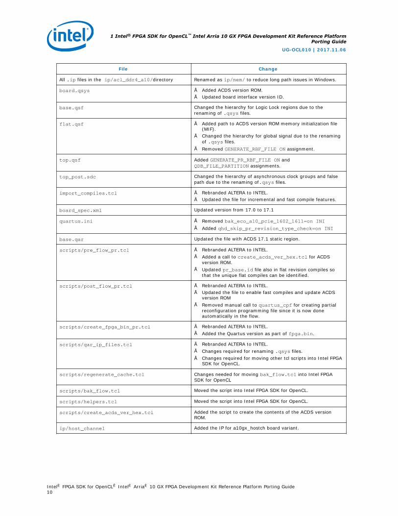
Table 3. Changes in a10_ref Reference Platform from 17.0 to 17.1
File Change
acl_ddr4_a10_core.qsys Renamed as ddr4.qsys to reduce long path issues in Windows.
All .ip files in the ip/acl_ddr4_a10_core/directory Renamed as ip/ddr4/ to reduce long path issues in Windows.
acl_ddr4_a10.qsys Renamed as mem.qsys to reduce long path issues in Windows.
continued...
1 Intel® FPGA SDK for OpenCL™ Intel Arria 10 GX FPGA Development Kit Reference PlatformPorting Guide
UG-OCL010 | 2017.11.06
Intel® FPGA SDK for OpenCL™ Intel® Arria® 10 GX FPGA Development Kit Reference Platform Porting Guide9
File Change
All .ip files in the ip/acl_ddr4_a10/directory Renamed as ip/mem/ to reduce long path issues in Windows.
board.qsys • Added ACDS version ROM.• Updated board interface version ID.
base.qsf Changed the hierarchy for Logic Lock regions due to therenaming of .qsys files.
flat.qsf • Added path to ACDS version ROM memory initialization file(MIF).
• Changed the hierarchy for global signal due to the renamingof .qsys files.
• Removed GENERATE_RBF_FILE ON assignment.
top.qsf Added GENERATE_PR_RBF_FILE ON andQDB_FILE_PARTITION assignments.
top_post.sdc Changed the hierarchy of asynchronous clock groups and falsepath due to the renaming of.qsys files.
import_compiles.tcl • Rebranded ALTERA to INTEL.• Updated the file for incremental and fast compile features.
board_spec.xml Updated version from 17.0 to 17.1
quartus.ini • Removed bak_eco_a10_pcie_1602_1611=on INI• Added qhd_skip_pr_revision_type_check=on INI
base.qar Updated the file with ACDS 17.1 static region.
scripts/pre_flow_pr.tcl • Rebranded ALTERA to INTEL.• Added a call to create_acds_ver_hex.tcl for ACDS
version ROM.• Updated pr_base.id file also in flat revision compiles so
that the unique flat compiles can be identified.
scripts/post_flow_pr.tcl • Rebranded ALTERA to INTEL.• Updated the file to enable fast compiles and update ACDS
version ROM• Removed manual call to quartus_cpf for creating partial
reconfiguration programming file since it is now doneautomatically in the flow.
scripts/create_fpga_bin_pr.tcl • Rebranded ALTERA to INTEL.• Added the Quartus version as part of fpga.bin.
scripts/qar_ip_files.tcl • Rebranded ALTERA to INTEL.• Changes required for renaming .qsys files.• Changes required for moving other tcl scripts into Intel FPGA
SDK for OpenCL.
scripts/regenerate_cache.tcl Changes needed for moving bak_flow.tcl into Intel FPGASDK for OpenCL
scripts/bak_flow.tcl Moved the script into Intel FPGA SDK for OpenCL.
scripts/helpers.tcl Moved the script into Intel FPGA SDK for OpenCL.
scripts/create_acds_ver_hex.tcl Added the script to create the contents of the ACDS versionROM.
ip/host_channel Added the IP for a10gx_hostch board variant.
1 Intel® FPGA SDK for OpenCL™ Intel Arria 10 GX FPGA Development Kit Reference PlatformPorting Guide
UG-OCL010 | 2017.11.06
Intel® FPGA SDK for OpenCL™ Intel® Arria® 10 GX FPGA Development Kit Reference Platform Porting Guide10

2 Developing Your Intel Arria 10 Custom PlatformUse the tools available in Intel Arria 10 GX FPGA Development Kit Reference Platform(a10_ref) and the Intel FPGA SDK for OpenCL Custom Platform Toolkit together tocreate your own Custom Platform.
Developing your Custom Platform requires in-depth knowledge of the contents in thefollowing documents and tools:
• Intel FPGA SDK for OpenCL Custom Platform User Guide
• Contents of the SDK Custom Platform Toolkit
• Stratix V Network Reference Platform Porting Guide
• Documentation for all the Intel FPGA IP in your Custom Platform
• Intel FPGA SDK for OpenCL Getting Started Guide
• Intel FPGA SDK for OpenCL Programming Guide
In addition, you must independently verify all IP on your computing card (for example,PCIe controllers and DDR4 external memory).
Related Links
• Intel FPGA SDK for OpenCL Custom Platform Toolkit User Guide
• Intel FPGA SDK for OpenCL Intel Arria 10 SoC Development Kit Reference PlatformPorting Guide
• Intel FPGA SDK for OpenCL Intel Cyclone V SoC Development Kit ReferencePlatform Porting Guide
• Intel FPGA SDK for OpenCL Intel Stratix V Network Reference Platform PortingGuide
• Intel FPGA SDK for OpenCL Getting Started Guide
• Intel FPGA SDK for OpenCL Programming Guide
2.1 Initializing Your Intel Arria 10 Custom Platform
To initialize your Intel FPGA SDK for OpenCL Custom Platform, copy the Intel Arria 10GX FPGA Development Kit Reference Platform to another directory and rename it.
UG-OCL010 | 2017.11.06
Intel Corporation. All rights reserved. Intel, the Intel logo, Altera, Arria, Cyclone, Enpirion, MAX, Nios, Quartusand Stratix words and logos are trademarks of Intel Corporation or its subsidiaries in the U.S. and/or othercountries. Intel warrants performance of its FPGA and semiconductor products to current specifications inaccordance with Intel's standard warranty, but reserves the right to make changes to any products and servicesat any time without notice. Intel assumes no responsibility or liability arising out of the application or use of anyinformation, product, or service described herein except as expressly agreed to in writing by Intel. Intelcustomers are advised to obtain the latest version of device specifications before relying on any publishedinformation and before placing orders for products or services.*Other names and brands may be claimed as the property of others.
ISO9001:2008Registered
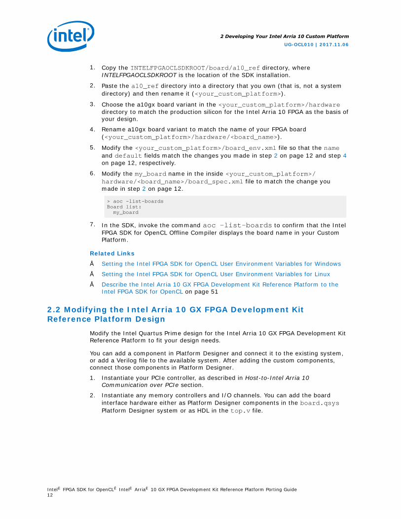
1. Copy the INTELFPGAOCLSDKROOT/board/a10_ref directory, whereINTELFPGAOCLSDKROOT is the location of the SDK installation.
2. Paste the a10_ref directory into a directory that you own (that is, not a systemdirectory) and then rename it (<your_custom_platform>).
3. Choose the a10gx board variant in the <your_custom_platform>/hardwaredirectory to match the production silicon for the Intel Arria 10 FPGA as the basis ofyour design.
4. Rename a10gx board variant to match the name of your FPGA board(<your_custom_platform>/hardware/<board_name>).
5. Modify the <your_custom_platform>/board_env.xml file so that the nameand default fields match the changes you made in step 2 on page 12 and step 4on page 12, respectively.
6. Modify the my_board name in the inside <your_custom_platform>/hardware/<board_name>/board_spec.xml file to match the change youmade in step 2 on page 12.
> aoc -list-boardsBoard list: my_board
7. In the SDK, invoke the command aoc -list-boards to confirm that the IntelFPGA SDK for OpenCL Offline Compiler displays the board name in your CustomPlatform.
Related Links
• Setting the Intel FPGA SDK for OpenCL User Environment Variables for Windows
• Setting the Intel FPGA SDK for OpenCL User Environment Variables for Linux
• Describe the Intel Arria 10 GX FPGA Development Kit Reference Platform to theIntel FPGA SDK for OpenCL on page 51
2.2 Modifying the Intel Arria 10 GX FPGA Development KitReference Platform Design
Modify the Intel Quartus Prime design for the Intel Arria 10 GX FPGA Development KitReference Platform to fit your design needs.
You can add a component in Platform Designer and connect it to the existing system,or add a Verilog file to the available system. After adding the custom components,connect those components in Platform Designer.
1. Instantiate your PCIe controller, as described in Host-to-Intel Arria 10Communication over PCIe section.
2. Instantiate any memory controllers and I/O channels. You can add the boardinterface hardware either as Platform Designer components in the board.qsysPlatform Designer system or as HDL in the top.v file.
2 Developing Your Intel Arria 10 Custom Platform
UG-OCL010 | 2017.11.06
Intel® FPGA SDK for OpenCL™ Intel® Arria® 10 GX FPGA Development Kit Reference Platform Porting Guide12

The board.qsys file and the top.v file are in the <your_custom_platform>/hardware/<board_name> directory.
3. Modify the device.tcl file to match all the correct settings for the device onyour board.
4. Modify the <your_custom_platform>/hardware/<board_name>/flat.qsffile to use only the pin-outs and settings for your system. The base.qsf,top.qsf, and top_synth.qsf files will include all the settings from theflat.qsf file.
The top.qsf file and top_synth.qsf file are in the<your_custom_platform>/hardware/<board_name> directory.
Related Links
Host-to-Intel Arria 10 FPGA Communication over PCIe on page 22
2.3 Integrating Your Intel Arria 10 Custom Platform with the IntelFPGA SDK for OpenCL
After you modify your Intel Quartus Prime design files, integrate your Custom Platformwith the Intel FPGA SDK for OpenCL.
1. Update the <your_custom_platform>/hardware/<board_name>/board_spec.xml file. Ensure that there is at least one global memory interface,and all the global memory interfaces correspond to the exported interfaces fromthe board.qsys Platform Designer System File.
2. Set the environment variable ACL_DEFAULT_FLOW to flat.
Setting this environment variable instructs the SDK to compile the flat revisioncorresponding to <your_custom_platform>/hardware/<board_name>/flat.qsf file without the partitions or Logic Locks.
Tip: Intel recommends to get a timing clean flat revision compiled beforeproceeding to the base revision compiles. You can also invoke the followingcommand with the -bsp-flow=<revision_type> attribute to run differentrevisions of your project (for example, flat or base compiles).
aoc -bsp-flow=flat boardtest.cl -o=bin/boardtest.aocx
3. Set the environment variable ACL_DEFAULT_FLOW to base.
Setting this environment variable instructs the SDK to compile the base revisioncorresponding to the <your_custom_platform>/hardware/<board_name>/base.qsf file.
4. Perform the steps outlined in the INTELFPGAOCLSDKROOT/board/custom_platform_toolkit/tests/README.txt file to compile theINTELFPGAOCLSDKROOT/board/custom_platform_toolkit/tests/boardtest/boardtest.cl OpenCL kernel source file.
2 Developing Your Intel Arria 10 Custom Platform
UG-OCL010 | 2017.11.06
Intel® FPGA SDK for OpenCL™ Intel® Arria® 10 GX FPGA Development Kit Reference Platform Porting Guide13
The environment variable INTELFPGAOCLSDKROOT points to the location of theSDK installation.
5. If compilation fails because of timing failures, fix the errors, or compileINTELFPGAOCLSDKROOT/board/custom_platform_toolkit/tests/boardtest.cl with different seeds. To compile the kernel with a different seed,include the -seed=<N> option in the aoc command (for example, aoc -seed=2 boardtest.cl).
You might be able to fix minor timing issues by simply compiling your kernel witha different seed.
Related Links
Describe the Intel Arria 10 GX FPGA Development Kit Reference Platform Hardware tothe Intel FPGA SDK for OpenCL on page 52
2.4 Setting up the Intel Arria 10 Custom Platform SoftwareDevelopment Environment
Prior to building the software layer for your Intel FPGA SDK for OpenCL CustomPlatform, set up the software development environment.
• To compile the MMD layer for Windows, perform the following tasks:
a. Install the GNU make utility on your development machine.
b. Install a version of Microsoft Visual Studio that has the ability to compile 64-bit software (for example, Microsoft Visual Studio version 2010 Professional).
c. Set the development environment so that SDK users can invoke commandsand utilities at the command prompt.
d. Modify the <your_custom_platform_name>/source/Makefile.commonfile so that TOP_DEST_DIR points to the top-level directory of your CustomPlatform.
e. In the Makefile.common file or the development environment, set theJUNGO_LICENSE variable to your Jungo WinDriver license.
f. To check that you have set up the software development environmentproperly, invoke the gmake or gmake clean command.
• To compile the MMD layer for Linux, perform the following tasks:
a. Ensure that you use a Linux distribution that Intel supports (for example, GNUCompiler Collection (GCC) version 4.47).
b. Modify the <your_custom_platform>/source/Makefile.common file sothat TOP_DEST_DIR points to the top-level directory of your Custom Platform.
• To check that you have set up the software environment properly, invoke the makeor make clean command.
Related Links
Jungo Connectivity Ltd. website
2 Developing Your Intel Arria 10 Custom Platform
UG-OCL010 | 2017.11.06
Intel® FPGA SDK for OpenCL™ Intel® Arria® 10 GX FPGA Development Kit Reference Platform Porting Guide14

2.5 Establishing Intel Arria 10 Custom Platform HostCommunication
After modifying and rebranding the Intel Arria 10 GX FPGA Development Kit ReferencePlatform to your own Custom Platform, use the tools and utilities in your CustomPlatform to establish communication between your FPGA accelerator board and yourhost application.
1. Program your FPGA device with the <your_custom_platform>/hardware/<board_name>/base.sof file and then reboot your system.
You should have created the base.sof file when integrating your CustomPlatform with the Intel FPGA SDK for OpenCL. Refer to the Integrating Your IntelArria 10 Custom Platform with the Intel FPGA SDK for OpenCL section for moreinformation.
2. Confirm that your operating system recognizes a PCIe device with your vendorand device IDs.
— For Windows, open the Device Manager and verify that the correct deviceand IDs appear in the listed information.
— For Linux, invoke the lspci command and verify that the correct device andIDs appear in the listed information.
3. Run the aocl install <path_to_customplatform> utility command toinstall the kernel driver on your machine.
4. For Windows, set the PATH environment variable. For Linux, set theLD_LIBRARY_PATH environment variable.
For more information about the settings for PATH and LD_LIBRARY_PATH, refer toSetting the Intel FPGA SDK for OpenCL User Environment Variables in the IntelFPGA SDK for OpenCL Getting Started Guide.
5. Modify the version_id_test function in your <your_custom_platform>/source/host/mmd/acl_pcie_device.cpp MMD source code file to exit afterreading from the version ID register.
6. Run the aocl diagnose utility command and confirm that the version IDregister reads back the ID successfully. You may set the environment variablesACL_HAL_DEBUG and ACL_PCIE_DEBUG to a value of 1 to visualize the result ofthe diagnostic test on your terminal.
Related Links
• Integrating Your Intel Arria 10 Custom Platform with the Intel FPGA SDK forOpenCL on page 13
• Setting the Intel FPGA SDK for OpenCL Environment Variables for Linux
• Setting the Intel FPGA SDK for OpenCL User Environment Variables for Windows
2.6 Branding Your Intel Arria 10 Custom Platform
Modify the library, driver and source files in the Intel Arria 10 GX FPGA DevelopmentKit Reference Platform to reference your Intel FPGA SDK for OpenCL Custom Platform.
2 Developing Your Intel Arria 10 Custom Platform
UG-OCL010 | 2017.11.06
Intel® FPGA SDK for OpenCL™ Intel® Arria® 10 GX FPGA Development Kit Reference Platform Porting Guide15

1. In the software development environment available with the a10_ref ReferencePlatform, replace all references of "a10_ref" with the name of your CustomPlatform.
2. Modify the PACKAGE_NAME and MMD_LIB_NAME fields in the<your_custom_platform>/source/Makefile.common file.
3. Modify the name, linklib, and mmlibs elements in<your_custom_platform>/board_env.xml file to your custom MMD libraryname.
4. In your Custom Platform, modify the following lines of code in thehw_pcie_constants.h file to include information of your Custom Platform:
#define ACL_BOARD_PKG_NAME "a10_ref"#define ACL_VENDOR_NAME "Intel Corporation"#define ACL_BOARD_NAME "Arria 10 Reference Platform"
For Windows, the hw_pcie_constants.h file is in the<your_custom_platform>\source_windows64\include folder. For Linux,the hw_pcie_constants.h file is in the <your_custom_platform>/linux64/driver directory.
Note: The ACL_BOARD_PKG_NAME variable setting must match the nameattribute of the board_env element that you specified in theboard_env.xml file.
5. Define the Device ID, Subsystem Vendor ID, Subsystem Device ID, and RevisionID, as defined in the Device Identification Registers for Intel Arria 10 PCIe Hard IPsection.
Note: The PCIe IDs in the hw_pcie_constants.h file must match theparameters in the PCIe controller hardware.
6. Update your Custom Platform's board.qsys Platform Designer system and thehw_pcie_constants.h file with the IDs defined in 5 on page 16.
7. For Windows, update DeviceList fields in the <your_custom_platform>\windows64\driver\acl_boards_a10_ref.inf file to match your PCIe IDvalues and then rename the file toacl_board_<your_custom_platform>.inf.
Note: The <your_custom_platform> string inacl_board_<your_custom_platform>.inf must match the string youspecify for the name field in the board_env.xml file.
8. Run make in the<your_custom_platform>/source directory to generate thedriver.
Related Links
Device Identification Registers for Intel Arria 10 PCIe Hard IP on page 24
2.7 Changing the Device Part Number
When porting the Intel Arria 10 GX FPGA Development Kit Reference Platform to yourown board, change the device part number, where applicable, to the part number ofthe device on your board.
2 Developing Your Intel Arria 10 Custom Platform
UG-OCL010 | 2017.11.06
Intel® FPGA SDK for OpenCL™ Intel® Arria® 10 GX FPGA Development Kit Reference Platform Porting Guide16

Update the device part number in the following files within the<your_custom_platform>/hardware/<board_name> directory:
• In the device.tcl file, change the device part number in the set globalassignment -name DEVICE 10AX115S2F45I1SG QSF assignment.The updated device number will appear in the base.qsf, top.qsf, andtop_synth.qsf files.
• In the board.qsys, mem.qsys, and ddr4.qsys files, change all occurrences of10AX115S2F45I1SG.
2.8 Connecting the Memory in the Intel Arria 10 Custom Platform
Calibrate the external memory IP and controllers in your Custom Platform, andconnect them to the host.
1. In your Custom Platform, instantiate your external memory IP based on theinformation in the DDR4 as Global Memory for OpenCL Applications section.Update the information pertaining to the global_mem element in the<your_custom_platform>/hardware/<board_name>/board_spec.xml file.
2. Remove the boardtest hardware configuration file that you created during theintegration of your Custom Platform with the Intel FPGA SDK for OpenCL.
3. Recompile the INTELFPGAOCLSDKROOT/board/custom_platform_toolkit/tests/boardtest/boardtest.cl kernel source file.
The environment variable INTELFPGAOCLSDKROOT points to the location of theSDK installation.
4. Reprogram the FPGA with the new boardtest hardware configuration file andthen reboot your machine.
5. Modify the wait_for_uniphy function in the acl_pcie_device.cpp MMDsource code file to exit after checking the UniPHY status register. Rebuild the MMDsoftware.
For Windows, the acl_pcie_device.cpp file is in the<your_custom_platform>\source\host\mmd folder. For Linux, theacl_pcie_device.cpp file is in the <your_custom_platform>/source/host/mmd directory.
6. Run the aocl diagnose SDK utility and confirm that the host reads back boththe version ID and the value 0 from the uniphy_status component.The utility should return the message Uniphy are calibrated.
7. Consider analyzing your design in the Signal Tap logic analyzer to confirm thesuccessful calibration of all memory controllers.
Note: For more information on Signal Tap logic analyzer, download the Signal TapII Logic Analyzer tutorial from the University Program Tutorial page.
Related Links
• DDR4 as Global Memory for OpenCL Applications on page 34
• Integrating Your Intel Arria 10 Custom Platform with the Intel FPGA SDK forOpenCL on page 13
• Signal Tap II with Verilog Designs
2 Developing Your Intel Arria 10 Custom Platform
UG-OCL010 | 2017.11.06
Intel® FPGA SDK for OpenCL™ Intel® Arria® 10 GX FPGA Development Kit Reference Platform Porting Guide17

2.9 Modifying the Kernel PLL Reference Clock
The Intel Arria 10 GX FPGA Reference Platform uses an external 125 MHz clock as areference for the I/O PLL. The I/O PLL relies on this reference clock to generate theinternal kernel_clk clock, and the kernel_clk2x clock that runs at twice thefrequency of kernel_clk. When porting the a10_ref Reference Platform to your ownboard using a different reference clock, update the board.qsys and top.sdc fileswith the new reference clock speed.
1. In the <your_custom_platform>/hardware/<board_name>/board.qsysfile, update the REF_CLK_RATE parameter value on the kernel_clk_gen IPmodule.
2. In the <your_custom_platform>/hardware/<board_name>/top.sdc file,update the create_clock assignment for kernel_pll_refclk.
3. [Optional] In the <your_custom_platform>/hardware/<board_name>/top.v file, update the comment for the kernel_pll_refclk input port.
After you update the board.qsys and the top.sdc files, the post_flow_pr.tclscript will automatically determine the I/O PLL reference frequency and compute thecorrect PLL settings.
2.10 Integrating an OpenCL Kernel in Your Intel Arria 10 CustomPlatform
After you establish host communication and connect the external memory, test theFPGA programming process from kernel creation to program execution.
1. Perform the steps outlined in INTELFPGAOCLSDKROOT/board/custom_platform_toolkit/tests/README.txt file to build the hardwareconfiguration file from the INTELFPGAOCLSDKROOT/board/custom_platform_toolkit/tests/boardtest/boardtest.cl kernel sourcefile.
The environment variable INTELFPGAOCLSDKROOT points to the location of theIntel FPGA SDK for OpenCL installation.
2. Program your FPGA device with the hardware configuration file you created in 1 onpage 18 and then reboot your machine.
3. Remove the early-exit modification in the version_id_test function in theacl_pcie_device.cpp file that you implemented when you establishedcommunication between the board and the host interface.
For Windows, the acl_pcie_device.cpp file is in the<your_custom_platform>\source\host\mmd folder. For Linux, theacl_pcie_device.cpp file is in the <your_custom_platform>/source/host/mmd directory.
4. Invoke the aocl diagnose <device_name> command, where<device_name> is the string you define in your Custom Platform to identify eachboard.
2 Developing Your Intel Arria 10 Custom Platform
UG-OCL010 | 2017.11.06
Intel® FPGA SDK for OpenCL™ Intel® Arria® 10 GX FPGA Development Kit Reference Platform Porting Guide18

By default, <device_name> is the acl number (for example, acl0 to acl31) thatcorresponds to your FPGA device. In this case, invoke the aocl diagnoseacl0 command.
5. Build the boardtest host application using the .sln file (Windows) or Makefile(Linux) in the SDK's Custom Platform Toolkit.
For Windows, the .sln file for Windows is in the INTELFPGAOCLSDKROOT\board\custom_platform_toolkit\tests\boardtest\host folder. For Linux, theMakefile is in the INTELFPGAOCLSDKROOT/board/custom_platform_toolkit/tests/boardtest directory.
6. Set the environment variable CL_CONTEXT_COMPILER_MODE_INTELFPGA to avalue of 3 and run the boardtest host application.
For more information on CL_CONTEXT_COMPILER_MODE_INTELFPGA, refer toTroubleshooting Intel Arria 10 GX FPGA Development Kit Reference PlatformPorting Issues.
Related Links
• Establishing Intel Arria 10 Custom Platform Host Communication on page 15
• Troubleshooting Intel Arria 10 GX FPGA Development Kit Reference PlatformPorting Issues on page 20
2.11 Guaranteeing Timing Closure in the Intel Arria 10 CustomPlatform
When modifying the Intel Arria 10 GX FPGA Development Kit Reference Platform intoyour own Custom Platform, ensure that guaranteed timing closure holds true for yourCustom Platform.
1. Establish the floorplan of your design.
Important: Consider all design criteria outlined in the FPGA System Design sectionof the Intel FPGA SDK for OpenCL Custom Platform Toolkit User Guide.
2. Compile several seeds of the INTELFPGAOCLSDKROOT/board/custom_platform_toolkit/tests/boardtest/boardtest.cl file until yougenerate a design that closes timing cleanly.
To specify the seed number, include the -seed=<N> option in your aoccommand.
3. Copy the base.qar file from the INTELFPGAOCLSDKROOT/board/a10_ref/hardware/a10gx directory into your Custom Platform.
4. Use the flat.qsf file in the a10_ref Reference Platform as references todetermine the type of information you must include in the flat.qsf file for yourCustom Platform.
The base.qsf, top.qsf, and top_synth.qsf files automatically inherit all thesettings in the flat.qsf file. However, if you need to modify Logic Lock Plusregion or PR assignments, only make these changes in the base.qsf file.
5. Confirm that you can use the .aocx file to reprogram the FPGA by invoking theaocl program acl0 boardtest.aocx command.
2 Developing Your Intel Arria 10 Custom Platform
UG-OCL010 | 2017.11.06
Intel® FPGA SDK for OpenCL™ Intel® Arria® 10 GX FPGA Development Kit Reference Platform Porting Guide19

6. Remove the ACL_DEFAULT_FLOW environment variable that you added whenintegrating your Custom Platform with the Intel FPGA SDK for OpenCL.
7. Ensure that the environment variable CL_CONTEXT_COMPILER_MODE_INTELFPGAis not set.
8. Run the boardtest_host executable.
Related Links
• Intel Arria 10 FPGA System Design on page 36
• FPGA System Design
• Integrating Your Intel Arria 10 Custom Platform with the Intel FPGA SDK forOpenCL on page 13
2.11.1 Generating the base.qar Post-Fit Netlist for Your Intel Arria 10Custom Platform
To implement the compilation flow, you must generate a base.qar Intel QuartusPrime Archive File for your Intel Arria 10 Custom Platform.
The steps below represent a general procedure for regenerating the base.qar file:
1. Port the system design and the flat.qsf file to your computing card.
2. Compile the INTELFPGAOCLSDKROOT/board/custom_platform_ toolkit/tests/boardtest/boardtest.cl kernel source file using the base revision. Fixany timing failures and recompile the kernel until timing is clean. You can add the-bsp-flow=base argument to the aoc command to generate a base.qar fileduring the kernel compilation.
INTELFPGAOCLSDKROOT points to the location of the Intel FPGA SDK for OpenCLinstallation.
3. Copy the generated base.qar file into your Custom Platform.
4. Using the default compilation flow, test the base.qar file across several OpenCLdesign examples and confirm that the following criteria are satisfied:
• All compilations close timing.
• The OpenCL design examples achieve satisfactory Fmax.
• The OpenCL design examples function on the accelerator board.
Related Links
• Integrating Your Intel Arria 10 Custom Platform with the Intel FPGA SDK forOpenCL on page 13
• Provide a Timing-Closed Post-Fit Netlist on page 45
2.12 Troubleshooting Intel Arria 10 GX FPGA Development KitReference Platform Porting Issues
Set Intel FPGA SDK for OpenCL-specific environment variables to help diagnoseCustom Platform design problems.
2 Developing Your Intel Arria 10 Custom Platform
UG-OCL010 | 2017.11.06
Intel® FPGA SDK for OpenCL™ Intel® Arria® 10 GX FPGA Development Kit Reference Platform Porting Guide20
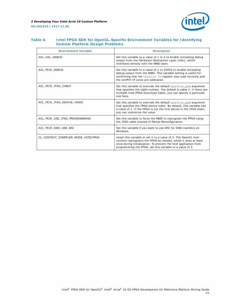
Table 4. Intel FPGA SDK for OpenCL-Specific Environment Variables for IdentifyingCustom Platform Design Problems
Environment Variable Description
ACL_HAL_DEBUG Set this variable to a value of 1 to 5 to enable increasing debugoutput from the Hardware Abstraction Layer (HAL), whichinterfaces directly with the MMD layer.
ACL_PCIE_DEBUG Set this variable to a value of 1 to 10000 to enable increasingdebug output from the MMD. This variable setting is useful forconfirming that the version ID register was read correctly andthe UniPHY IP cores are calibrated.
ACL_PCIE_JTAG_CABLE Set this variable to override the default quartus_pgm argumentthat specifies the cable number. The default is cable 1. If there aremultiple Intel FPGA Download Cable, you can specify a particularone here.
ACL_PCIE_JTAG_DEVICE_INDEX Set this variable to override the default quartus_pgm argumentthat specifies the FPGA device index. By default, this variable hasa value of 1. If the FPGA is not the first device in the JTAG chain,you can customize the value.
ACL_PCIE_USE_JTAG_PROGRAMMING Set this variable to force the MMD to reprogram the FPGA usingthe JTAG cable instead of Partial Reconfiguration.
ACL_PCIE_DMA_USE_MSI Set this variable if you want to use MSI for DMA transfers onWindows.
CL_CONTEXT_COMPILER_MODE_INTELFPGA Unset this variable or set it to a value of 3. The OpenCL hostruntime reprograms the FPGA as needed, which it does at leastonce during initialization. To prevent the host application fromprogramming the FPGA, set this variable to a value of 3.
2 Developing Your Intel Arria 10 Custom Platform
UG-OCL010 | 2017.11.06
Intel® FPGA SDK for OpenCL™ Intel® Arria® 10 GX FPGA Development Kit Reference Platform Porting Guide21

3 Intel Arria 10 GX FPGA Development Kit ReferencePlatform Design Architecture
Intel created the Intel Arria 10 GX FPGA Development Kit Reference Platform(a10_ref) based on various design considerations. Familiarize yourself with thesedesign considerations. Having a thorough understanding of the design decision-making process might help in the design of your own Intel FPGA SDK for OpenCLCustom Platform.
Host-to-Intel Arria 10 FPGA Communication over PCIe on page 22
DDR4 as Global Memory for OpenCL Applications on page 34
Host Connection to OpenCL Kernels on page 36
Intel Arria 10 FPGA System Design on page 36
Dynamic PLL Reconfiguration on page 43
Guaranteed Timing Closure of the Intel Arria 10 GX FPGA Development Kit ReferencePlatform Design on page 43
Intel Quartus Prime Compilation Flow and Scripts on page 46
Addition of Timing Constraints on page 51
Connection of the Intel Arria 10 GX FPGA Development Kit Reference Platform to theIntel FPGA SDK for OpenCL on page 51
Intel Arria 10 FPGA Programming Flow on page 53
Host-to-Device MMD Software Implementation on page 54
Implementation of Intel FPGA SDK for OpenCL Utilities on page 55
Intel Arria 10 FPGA Development Kit Reference Platform Scripts on page 58
Considerations in Intel Arria 10 GX FPGA Development Kit Reference PlatformImplementation on page 59
3.1 Host-to-Intel Arria 10 FPGA Communication over PCIe
The Intel Arria 10 GX FPGA Development Kit Reference Platform instantiates the IntelArria 10 PCIe hard IP to implement a host-to-device connection over PCIe.
3.1.1 Instantiation of Intel Arria 10 PCIe Hard IP with Direct MemoryAccess
The Intel Arria 10 GX FPGA Development Kit Reference Platform instantiates the IntelArria 10 PCIe hard IP with direct memory access (DMA) to implement a host-to-deviceconnection over PCIe.
UG-OCL010 | 2017.11.06
Intel Corporation. All rights reserved. Intel, the Intel logo, Altera, Arria, Cyclone, Enpirion, MAX, Nios, Quartusand Stratix words and logos are trademarks of Intel Corporation or its subsidiaries in the U.S. and/or othercountries. Intel warrants performance of its FPGA and semiconductor products to current specifications inaccordance with Intel's standard warranty, but reserves the right to make changes to any products and servicesat any time without notice. Intel assumes no responsibility or liability arising out of the application or use of anyinformation, product, or service described herein except as expressly agreed to in writing by Intel. Intelcustomers are advised to obtain the latest version of device specifications before relying on any publishedinformation and before placing orders for products or services.*Other names and brands may be claimed as the property of others.
ISO9001:2008Registered
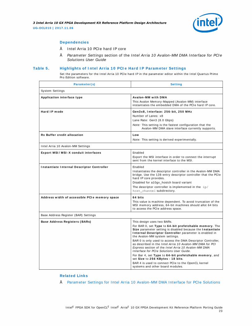
Dependencies
• Intel Arria 10 PCIe hard IP core
• Parameter Settings section of the Intel Arria 10 Avalon-MM DMA Interface for PCIeSolutions User Guide
Table 5. Highlights of Intel Arria 10 PCIe Hard IP Parameter SettingsSet the parameters for the Intel Arria 10 PCIe hard IP in the parameter editor within the Intel Quartus PrimePro Edition software.
Parameter(s) Setting
System Settings
Application interface type Avalon-MM with DMAThis Avalon Memory-Mapped (Avalon-MM) interfaceinstantiates the embedded DMA of the PCIe hard IP core.
Hard IP mode Gen3x8, Interface: 256-bit, 250 MHzNumber of Lanes: x8Lane Rate: Gen3 (8.0 Gbps)Note: This setting is the fastest configuration that the
Avalon-MM DMA slave interface currently supports.
Rx Buffer credit allocation LowNote: This setting is derived experimentally.
Intel Arria 10 Avalon-MM Settings
Export MSI/MSI-X conduit interfaces EnabledExport the MSI interface in order to connect the interruptsent from the kernel interface to the MSI.
Instantiate Internal Descriptor Controller EnabledInstantiates the descriptor controller in the Avalon-MM DMAbridge. Use the 128-entry descriptor controller that the PCIehard IP core provides.Disabled for a10gx_hostch board variantThe descriptor controller is implemented in the ip/host_channel subdirectory.
Address width of accessible PCIe memory space 64 bitsThis value is machine dependent. To avoid truncation of theMSI memory address, 64-bit machines should allot 64 bitsto access the PCIe address space.
Base Address Register (BAR) Settings
Base Address Registers (BARs) This design uses two BARs.For BAR 0, set Type to 64-bit prefetchable memory. TheSize parameter setting is disabled because the InstantiateInternal Descriptor Controller parameter is enabled inthe Avalon-MM system settings.BAR 0 is only used to access the DMA Descriptor Controller,as described in the Intel Arria 10 Avalon-MM DMA for PCIExpress section of the Intel Arria 10 Avalon-MM DMAInterface for PCIe Solutions User Guide.For Bar 4, set Type to 64-bit prefetchable memory, andset Size to 256 KBytes - 18 bits.BAR 4 is used to connect PCIe to the OpenCL kernelsystems and other board modules.
Related Links
• Parameter Settings for Intel Arria 10 Avalon-MM DMA Interface for PCIe Solutions
3 Intel Arria 10 GX FPGA Development Kit Reference Platform Design Architecture
UG-OCL010 | 2017.11.06
Intel® FPGA SDK for OpenCL™ Intel® Arria® 10 GX FPGA Development Kit Reference Platform Porting Guide23

• Intel Arria 10 Avalon-MM DMA for PCI Express
3.1.2 Device Identification Registers for Intel Arria 10 PCIe Hard IP
To build PCIe hardware, you must set PCIe IDs related to the device hardware.
Table 6. Device Hardware-Related PCIe ID Registers
ID Register Name ID Provider Description Parameter Name in PCIeIP Core
Vendor ID PCI-SIG® Identifies the FPGA manufacturer.Always set this register to 0x1172, which is Intelvendor ID.
vendor_id_hwtcl
Device ID Intel Describes the PCIe configuration on the FPGAaccording to Intel's internal guideline.Set the device ID to the device code of the FPGAon your accelerator board.For the Intel Arria 10 GX FPGA Development KitReference Platform, set the Device ID register to0x2494, which signifies Gen 3 speed, 8 lanes,Intel Arria 10 device family, and Avalon-MMinterface, respectively.Refer to Table 7 on page 25 for more information.
device_id_hwtcl
Revision ID When setting this ID, ensure that it matches thefollowing revision IDs:• For Windows, the revision ID specified for the
DeviceList field in the<your_custom_platform>\windows64\driver\acl_boards_<your_custom_platform>.inf file.
• For Linux, the revision ID specified for theACL_PCI_REVISION variable in the<your_custom_platform>/linux64/driver/hw_pcie_constants.h file.
—
Class Code Intel The Intel FPGA SDK for OpenCL utility checks thebase class value to verify whether the board is anOpenCL device.Do not modify the class code settings.• Base class: 0x12 for processing accelerator• Sub class: 0x00• Programming interface: 0x01
—
SubsystemVendor ID
Board vendor Identifies the manufacturer of the acceleratorboard.Set this register to the vendor ID of manufacturerof your accelerator board. For the a10_refReference Platform, the subsystem vendor ID is0x1172.If you are a board vendor, set this register to yourvendor ID.
subsystem_vendor_id_hwtcl
SubsystemDevice ID
Board vendor Identifies the accelerator board.The SDK uses this ID to identify the board becausethe software might perform differently on differentboards. If you create a Custom Platform thatsupports multiple boards, use this ID to distinguishbetween the boards. Alternatively, if you havemultiple Custom Platforms, each supporting asingle board, you can use this ID to distinguishbetween the Custom Platforms.
subsystem_device_id_hwtcl
continued...
3 Intel Arria 10 GX FPGA Development Kit Reference Platform Design Architecture
UG-OCL010 | 2017.11.06
Intel® FPGA SDK for OpenCL™ Intel® Arria® 10 GX FPGA Development Kit Reference Platform Porting Guide24

ID Register Name ID Provider Description Parameter Name in PCIeIP Core
Important: Make this ID unique to your CustomPlatform. For example, for the a10_refReference Platform, the ID is0xA151.
You can find these PCIe ID definitions in the PCIe controller instantiated in theINTELFPGAOCLSDKROOTboard/a10_ref/hardware/a10gx/board.qsys PlatformDesigner System File. These IDs are necessary in the driver and the SDK'sprogramming flow. The kernel driver uses the Vendor ID, Subsystem Vendor IDand the Subsystem Device ID to identify the boards it supports. The SDK'sprogramming flow checks the Device ID to ensure that it programs a device witha .aocx Intel FPGA SDK for OpenCL Offline Compiler executable file targeting thatspecific device.
Table 7. Intel FPGA SDK for OpenCL's Numbering Convention for PCIe Hard IP DeviceID
Location in ID Definition
15:14 RESERVED
13:12 Speed• 0 — Gen 1• 1 — Gen 2• 2 — Gen 3• 3 — Gen 4
11 RESERVED
10:8 Number of lanes• 0 — 1 lane• 1 — 2 lanes• 3 — 4 lanes• 4 — 8 lanes• 5 — 16 lanes• 6 — 32 lanes
7:4 Device family• 0 — Altera Stratix IV GX• 1 — Altera Arria II GX• 2 — Stratix II GX• 3 — Arria GX• 4 — Cyclone IV GX• 5 — External• 6 — Stratix V• 7 — Arria V• 8 — Cyclone V• 9 — Arria 10
3 1 — Soft IP (SIP)This ID indicates that the PCIe protocol stack is implemented in soft logic.If unspecified, the IP is considered a hard IP.
2:0 Platform Designer PCIe interface typecontinued...
3 Intel Arria 10 GX FPGA Development Kit Reference Platform Design Architecture
UG-OCL010 | 2017.11.06
Intel® FPGA SDK for OpenCL™ Intel® Arria® 10 GX FPGA Development Kit Reference Platform Porting Guide25

Location in ID Definition
• 0 — 64 bits• 1 — 128 bits• 2 — 256 bits• 3 — Desc/Data (that is, Avalon-Streaming (Avalon-ST) interface)• 4 — Avalon-MM interface
3.1.3 Instantiation of the version_id Component
Intel specifies an additional version ID and uses it to verify the address map of thesystem. The host verifies the version ID of the Intel Arria 10 GX FPGA DevelopmentKit Reference Platform when instantiating the version_id component that connects tothe PCIe Avalon master.
The version ID for the a10_ref Reference Platform is A0C7C1E6 in 17.1 release.
Before communicating with any part of the FPGA system, the host first reads from thisversion_id register to confirm the following:
• The PCIe can access the FPGA fabric successfully.
• The address map matches the map in the MMD software.
Update the VERSION_ID parameter in the version_id component to a new value withevery slave addition or removal from the PCIe BAR 4 bus, or whenever the addressmap changes.
3.1.4 Definitions of Intel Arria 10 FPGA Development Kit ReferencePlatform Hardware Constraints in Software Headers Files
After you build the PCIe component in your hardware design, you need a softwarelayer to communicate with the board via PCIe. To enable communication between theboard and the host interface, define the hardware constants for the software in headerfiles.
The two header files that describe the hardware design to the software are in thefollowing locations:
• For Windows systems, the header files are in the INTELFPGAOCLSDKROOT\board\a10_ref\source\include folder, where INTELFPGAOCLSDKROOT is the pathto the SDK installation.
• For Linux systems, the header files are in the INTELFPGAOCLSDKROOT/board/a10_ref/linux64/driver directory.
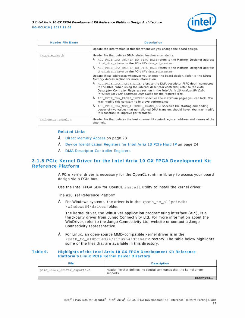
Table 8. Intel Arria 10 GX FPGA Development Kit Reference Platform Header Files
Header File Name Description
hw_pcie_constants.h Header file that defines most of the hardware constants for the board design.This file includes constants such as the IDs described in PCIe Device IdentificationRegisters, BAR number, and offset for different components in your design. Inaddition, this header file also defines the name strings of ACL_BOARD_PKG_NAME,ACL_VENDOR_NAME, and ACL_BOARD_NAME.
continued...
3 Intel Arria 10 GX FPGA Development Kit Reference Platform Design Architecture
UG-OCL010 | 2017.11.06
Intel® FPGA SDK for OpenCL™ Intel® Arria® 10 GX FPGA Development Kit Reference Platform Porting Guide26
Header File Name Description
Update the information in this file whenever you change the board design.
hw_pcie_dma.h Header file that defines DMA-related hardware constants.• ACL_PCIE_DMA_ONCHIP_RD_FIFO_BASE refers to the Platform Designer address
of rd_dts_slave on the PCIe IP's dma_rd_master.• ACL_PCIE_DMA_ONCHIP_WR_FIFO_BASE refers to the Platform Designer address
of wr_dts_slave on the PCIe IP's dma_rd_master.Update these addresses whenever you change the board design. Refer to the DirectMemory Access section for more information.• ACL_PCIE_DMA_TABLE_SIZE refers to the DMA descriptor FIFO depth connected
to the DMA. When using the internal descriptor controller, refer to the DMADescriptor Controller Registers section in the Intel Arria 10 Avalon-MM DMAInterface for PCIe Solutions User Guide for the required size.
• ACL_PCIE_DMA_PAGES_LOCKED specifies the maximum pages you can lock. Youmay modify this constant to improve performance.
• ACL_PCIE_DMA_NON_ALIGNED_TRANS_LOG specifies the starting and endingpower-of-two values that non-aligned DMA transfers should have. You may modifythis constant to improve performance.
hw_host_channel.h Header file that defines the host channel IP control register address and names of thechannels.
Related Links
• Direct Memory Access on page 28
• Device Identification Registers for Intel Arria 10 PCIe Hard IP on page 24
• DMA Descriptor Controller Registers
3.1.5 PCIe Kernel Driver for the Intel Arria 10 GX FPGA Development KitReference Platform
A PCIe kernel driver is necessary for the OpenCL runtime library to access your boarddesign via a PCIe bus.
Use the Intel FPGA SDK for OpenCL install utility to install the kernel driver.
The a10_ref Reference Platform
• For Windows systems, the driver is in the <path_to_al0pciedk>\windows64\driver folder.
The kernel driver, the WinDriver application programming interface (API), is athird-party driver from Jungo Connectivity Ltd. For more information about theWinDriver, refer to the Jungo Connectivity Ltd. website or contact a JungoConnectivity representative.
• For Linux, an open-source MMD-compatible kernel driver is in the<path_to_al0pciedk>/linux64/driver directory. The table below highlightssome of the files that are available in this directory.
Table 9. Highlights of the Intel Arria 10 GX FPGA Development Kit ReferencePlatform's Linux PCIe Kernel Driver Directory
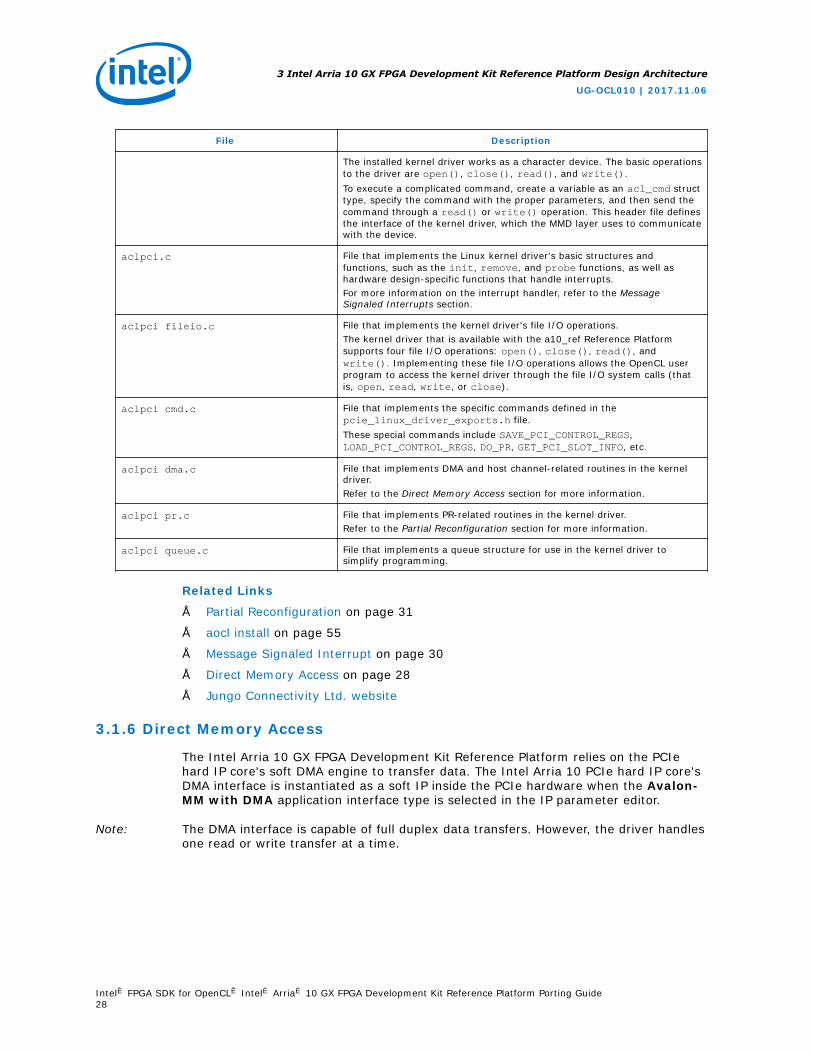
File Description
pcie_linux_driver_exports.h Header file that defines the special commands that the kernel driversupports.
continued...
3 Intel Arria 10 GX FPGA Development Kit Reference Platform Design Architecture
UG-OCL010 | 2017.11.06
Intel® FPGA SDK for OpenCL™ Intel® Arria® 10 GX FPGA Development Kit Reference Platform Porting Guide27
File Description
The installed kernel driver works as a character device. The basic operationsto the driver are open(), close(), read(), and write().To execute a complicated command, create a variable as an acl_cmd structtype, specify the command with the proper parameters, and then send thecommand through a read() or write() operation. This header file definesthe interface of the kernel driver, which the MMD layer uses to communicatewith the device.
aclpci.c File that implements the Linux kernel driver's basic structures andfunctions, such as the init, remove, and probe functions, as well ashardware design-specific functions that handle interrupts.For more information on the interrupt handler, refer to the MessageSignaled Interrupts section.
aclpci fileio.c File that implements the kernel driver's file I/O operations.The kernel driver that is available with the a10_ref Reference Platformsupports four file I/O operations: open(), close(), read(), andwrite(). Implementing these file I/O operations allows the OpenCL userprogram to access the kernel driver through the file I/O system calls (thatis, open, read, write, or close).
aclpci cmd.c File that implements the specific commands defined in thepcie_linux_driver_exports.h file.These special commands include SAVE_PCI_CONTROL_REGS,LOAD_PCI_CONTROL_REGS, DO_PR, GET_PCI_SLOT_INFO, etc.
aclpci dma.c File that implements DMA and host channel-related routines in the kerneldriver.Refer to the Direct Memory Access section for more information.
aclpci pr.c File that implements PR-related routines in the kernel driver.Refer to the Partial Reconfiguration section for more information.
aclpci queue.c File that implements a queue structure for use in the kernel driver tosimplify programming.
Related Links
• Partial Reconfiguration on page 31
• aocl install on page 55
• Message Signaled Interrupt on page 30
• Direct Memory Access on page 28
• Jungo Connectivity Ltd. website
3.1.6 Direct Memory Access
The Intel Arria 10 GX FPGA Development Kit Reference Platform relies on the PCIehard IP core's soft DMA engine to transfer data. The Intel Arria 10 PCIe hard IP core'sDMA interface is instantiated as a soft IP inside the PCIe hardware when the Avalon-MM with DMA application interface type is selected in the IP parameter editor.
Note: The DMA interface is capable of full duplex data transfers. However, the driver handlesone read or write transfer at a time.
3 Intel Arria 10 GX FPGA Development Kit Reference Platform Design Architecture
UG-OCL010 | 2017.11.06
Intel® FPGA SDK for OpenCL™ Intel® Arria® 10 GX FPGA Development Kit Reference Platform Porting Guide28
Hardware Considerations
The instantiation process exports the DMA controller slave ports (that is,rd_dts_slave and wr_dts_slave) and master ports (that is, rd_dcm_master andwr_dcm_master) into the PCIe module. Two additional master ports,dma_rd_master and dma_wr_master, are exported for DMA read and writeoperations, respectively. For the DMA interface to function properly, all these portsmust be connected correctly in the board.qsys Platform Designer system, where thePCIe hard IP is instantiated.
At the start of DMA transfer, the DMA Descriptor Controller reads from the DMAdescriptor table in user memory, and stores the status and the descriptor table into aFIFO address. There are two FIFO addresses: Read Descriptor FIFO address andWrite Descriptor FIFO address. After storing the descriptor table into a FIFOaddress, DMA transfer into the FIFO address can occur. The dma_rd_master port,which moves data from user memory to the device, must connect to therd_dts_slave and wr_dts_slave ports. Because the dma_rd_master portconnects to DDR4 memory also, the locations of the rd_dts_slave andwr_dts_slave ports in the address space must be defined in the hw_pcie_dma.hfile.
The rd_dcm_master and wr_dcm_master ports must connect to the txs port. Atthe end of the DMA transfer, the DMA controller writes the MSI data and the donestatus into the user memory via the txs slave. The txs slave is part of the PCIe hardIP in board.qsys.
All modules that use DMA must connect to the dma_rd_master and dma_wr_masterports. For DDR4 memory connection, Intel recommends implementing an additionalpipeline to connect the two 256-bit PCIe DMA ports to the 512-bit memory slave. Formore information, refer to the DDR4 Connection to PCIe Host section.
Software Considerations
The MMD layer uses DMA to transfer data if it receives a data transfer request thatsatisfies both of the following conditions:
• A transfer size that is greater than 1024 bytes.
• The starting addresses for both the host buffer and the device offset are aligned to64 bytes.
Related Links
• Definitions of Intel Arria 10 FPGA Development Kit Reference Platform HardwareConstraints in Software Headers Files on page 26
• Intel Arria 10 DMA Avalon-MM DMA Interface to the Application Layer
• DMA Descriptor Controller Registers
• Implementing a DMA Transfer on page 30
• DDR4 Connection to PCIe Host on page 35
3 Intel Arria 10 GX FPGA Development Kit Reference Platform Design Architecture
UG-OCL010 | 2017.11.06
Intel® FPGA SDK for OpenCL™ Intel® Arria® 10 GX FPGA Development Kit Reference Platform Porting Guide29

3.1.6.1 Implementing a DMA Transfer
Implement a DMA transfer in the MMD on Windows (INTELFPGAOCLSDKROOT\board\a10_ref\source\host\mmd\acl_pcie_dma_windows.cpp) or in the kerneldriver on Linux (INTELFPGAOCLSDKROOT/board/a10_ref/linux64/driver/aclpci_dma).
Note: For Windows, the Jungo WinDriver imposes a 5000 to 10000 limit on the number ofinterrupts received per second in user mode. This limit translates to a 2.5 gigabytesper second (GBps) to 5 GBps DMA bandwidth when a full 128-entry table of 4 KB pageis transferred per interrupt.
On Windows, polling is the default method for maximizing PCIe DMA bandwidth at theexpense of CPU run time. To use interrupts instead of polling, assign a non-NULL valueto the ACL_PCIE_DMA_USE_MSI environment variable.
The steps below describe the general procedure for implementing a DMA transfer:
1. Verify that the previous DMA transfer sent all the requested bytes of data.
2. Map the virtual memories that are requested for DMA transfer to physicaladdresses.
Note: The amount of virtual memory that can be mapped at a time is systemdependent. Large DMA transfers will require multiple mapping or unmappingoperations. For a higher bandwidth, map the virtual memory ahead in aseparate thread that is in parallel to the transfer.
3. Set up the DMA descriptor table on local memory.
4. Write the location of the DMA descriptor table, which is in user memory, to theDMA control registers (that is, RC Read Status and Descriptor Base andRC Write Status and Descriptor Base).
5. Write the Platform Designer address of descriptor FIFOs to the DMA controlregisters (that is EP Read Descriptor FIFO Base and EP Write Statusand Descriptor FIFO Base).
6. Write the start signal to the RD_DMA_LAST_PTR and WR_DMA_LAST_PTR DMAcontrol registers.
7. After the current DMA transfer finishes, repeat the procedure to implement thenext DMA transfer.
Related Links
Direct Memory Access on page 28
3.1.7 Message Signaled Interrupt
The Intel Arria 10 GX FPGA Development Kit Reference Platform uses one MSI line forboth DMA and the kernel interface.
Two different modules generate the signal for the MSI line. The DMA controller in thePCIe hard IP core generates the DMA's MSI. The PCI Express interrupt request (IRQ)module (that is, the INTELFPGAOCLSDKROOT/board/a10_ref/hardware/a10gx/ip/irq_controller directory) generates the kernel interface's MSI.
For more information on the PCI Express IRQ module, refer to Handling PCIeInterrupts webpage.
3 Intel Arria 10 GX FPGA Development Kit Reference Platform Design Architecture
UG-OCL010 | 2017.11.06
Intel® FPGA SDK for OpenCL™ Intel® Arria® 10 GX FPGA Development Kit Reference Platform Porting Guide30

Hardware Considerations
In INTELFPGAOCLSDKROOT/board/a10_ref/hardware/a10gx/board.qsys, theDMA MSI is connected internally; however, you must connect the kernel interfaceinterrupt manually. For the kernel interface interrupt, the PCI Express IRQ module isinstantiated as pcie_irq_0 in board.qsys. The kernel interface interruptsconnections are as follows:
• The kernel_irq_to_host port from the OpenCL Kernel Interface(kernel_interface) connects to the interrupt receiver, which allows theOpenCL kernels to signal the PCI Express IRQ module to send an MSI.
• The PCIe hard IP's msi_intfc port connects to the MSI_Interface port in thePCI Express IRQ module. The kernel interface interrupt receives the MSI addressand the data necessary to generate the interrupt via msi_intfc.
• The IRQ_Gen_Master port on the PCI Express IRQ module, which is used to writethe MSI, connects to the txs port on the PCIe hard IP.
• The IRQ_Read_Slave and IRQ_Mask_Slave ports connect to thepipe_stage_host_ctrl module on Bar 4. After receiving an MSI, the userdriver can read the IRQ_Read_Slave port to check the status of the kernelinterface interrupt, and read the IRQ_Mask_Slave port to mask the interrupt.
Software Considerations
The interrupt service routine in the Linux driver checks which module generates theinterrupt. For the DMA's MSI, the driver reads the DMA descriptor table's status bit inlocal memory, as specified in the Read DMA Example section of the Intel Arria 10Avalon-MM DMA Interface for PCIe Solutions User Guide. For kernel interface's MSI,the driver reads the interrupt line sent by the kernel interface.
The interrupt service routine involves the following tasks:
1. Check DMA status on the DMA descriptor table.
2. Read the kernel status from the IRQ_READ_SLAVE port on the PCI Express IRQmodule.
3. If a kernel interrupt was triggered, mask the interrupt by writing to theIRQ_MASK_SLAVE port on the PCI Express IRQ module. Then, execute the kernelinterrupt service routine.
4. If a DMA interrupt was triggered, reset the DMA descriptor table and execute theDMA interrupt service routine.
5. If applicable, unmask a masked kernel interrupt.
Related Links
• Handling PCIe Interrupts
• Read DMA Example
3.1.8 Partial Reconfiguration
The Intel Arria 10 GX FPGA Development Kit Reference Platform uses partialreconfiguration (PR) as a default mechanism to reconfigure the OpenCL kernel-relatedpartition of the design without altering the static board interface that is in a runningstate.
3 Intel Arria 10 GX FPGA Development Kit Reference Platform Design Architecture
UG-OCL010 | 2017.11.06
Intel® FPGA SDK for OpenCL™ Intel® Arria® 10 GX FPGA Development Kit Reference Platform Porting Guide31

You can only use PR when the static board interface, generated during basecompilations, matches the static region of the design that is used to compile theOpenCL kernel's PR region.
For Windows MMD implementation, the INTELFPGAOCLSDKROOT\board\a10_ref\source\host\mmd\acl_pcie_config.cpp file contains the MMD code thatcommunicates with the PR configuration controller within the static region of thedesign. The program_core_with_PR_file function within theacl_pcie_config.cpp file requires a handle to the PR bitstream and the length ofthe PR bitstream in order to perform the PR operation.
For Linux driver implementation, the INTELFPGAOCLSDKROOT/board/a10_ref/linux64/driver/aclpci_pr.c file includes the main host driver routine thatcommunicates with the PR configuration controller within the static region of thedesign. The aclpci_pr function within the acl_pci_pr.c file requires the followinginformation in order to perform the PR operation:
• A handle to the board
• A handle to the PR bitstream
• The length of the PR bitstream
After verifying that the device is opened, the bitstream is of adequate length, and thePCIe endpoint of the device is reachable, the aclpci_pr function writes 0x1 to thePR IP status register. Then, the aclpci_pr function writes the complete bitstream, 32bits at a time, to the PR IP. After the bitstream transfer is complete, the aclpci_prfunction performs a read operation to the PR IP status register to verify whether PR issuccessful. A return value of 0x14 indicates a successful PR operation; any otherreturn value indicates an error.
To override the default reconfiguration mechanism, set theACL_PCIE_USE_JTAG_PROGRAMMING environment variable, as shown below:
• For Windows, type set ACL_PCIE_USE_JTAG_PROGRAMMING=1 at the commandprompt.
• For Linux, type export ACL_PCIE_USE_JTAG_PROGRAMMING=1 at the commandprompt.
Setting ACL_PCIE_USE_JTAG_PROGRAMMING specifies that JTAG full-chipconfiguration is the default mechanism for reconfiguring the device.
Related Links
Partial Reconfiguration IP Core
3.1.9 Cable Autodetect
If partial reconfiguration (PR) cannot be used or fails to reconfigure the OpenCLkernel-related partition of the design, an attempt is made to do a full JTAGprogramming over the Intel FPGA Download Cable (formerly USB-Blaster).
The Intel Arria 10 GX FPGA Development Kit Reference Platform automatically tries todetect the cable by default when programming the FPGA via the Intel FPGA DownloadCable.
3 Intel Arria 10 GX FPGA Development Kit Reference Platform Design Architecture
UG-OCL010 | 2017.11.06
Intel® FPGA SDK for OpenCL™ Intel® Arria® 10 GX FPGA Development Kit Reference Platform Porting Guide32

You can set the ACL_PCIE_JTAG_CABLE or ACL_PCIE_JTAG_DEVICE_INDEXenvironment variables to disable the auto-detect feature and use values that youdefine.
Cable autodetect is useful when you have multiple devices connected to a single hostand PR cannot be used to program the FPGA.
The memory-mapped device (MMD) uses in-system sources and probes to identify thecable connected to the target board. You must instantiate the cade_id register blockand connect it to Bar 4 with the correct address map. You must also instantiateboard_in_system_sources_probes_cade_id, which is an in-system sources andprobe component, and connect it to cade_id register.
The MMD must be updated to take in the relevant changes. Add the scripts/find_jtag_cable.tcl script to be added to your custom platform.
When the FPGA is being programmed via the Intel FPGA Download Cable, the MMDinvokes quartus_stp to execute the find_jtag_cable.tcl script. The scriptidentifies the cable and index number which is then used to program the FPGAthrough the quartus_pgm command.
3.1.10 Host Channel
The a10gx_hostch board variant of Intel Arria 10 GX FPGA Development Kit ReferencePlatform uses host channel to provide direct streaming interface between OpenCL hostand kernel by using DMA.
The streaming interface makes use of DMA.
3.1.10.1 Host Channel IP Instantiation
In Platform Designer, the host channel IP can be instantiated from Intel Arria 10 boardsupport package components in the IP catalog. The name of the IP isacl_hostchannel_top.
Table 10. Host Channel Top Configuration Setting
IP Parameters Description
HOST_CHANNEL_DEPTH - 2048 Depth of the internal buffer that DMA transfers data to andfrom.There are two buffers, and both of their depths are set bythis parameter.
HOST_CHANNEL_VALID_BUFFER_USE_LAB - 0 Set to 1 to use LABs to instantiate the internal buffer, and 0to use block RAMs.
3.1.10.2 Host Channel Top Connection to PCIe DMA
In addition to the ports connected in DMA section, by disabling Instantiateinternal descriptor controller setting on Intel Arria 10 Hard IP for PCIExpress, ReadDCS, WrDCS, rd_ast_rx, wr_ast_rx, RdDmaRx and WrDmaRx portsare exposed on the IP.
These ports must be connected to the DMA descriptor controller in the host channel IP.
3 Intel Arria 10 GX FPGA Development Kit Reference Platform Design Architecture
UG-OCL010 | 2017.11.06
Intel® FPGA SDK for OpenCL™ Intel® Arria® 10 GX FPGA Development Kit Reference Platform Porting Guide33

Base address offset must match the address mentioned in the board.qsys file, sincethese addresses are used by the internal descriptor controller of a10gx board variant.
You need to make the following connections:
• On acl_hostchannel_top IP, rd_dma and wr_dma ports are used to receiveand send data to DMA. These ports must be connected to the corresponding portson PCIe IP with base address offset matching in the hw_host_channel.h headerfile.
• The cra port must be connected to the host_ctrl.
• The msi_interface port must be connected to Intel Arria 10 Hard IP for PCIExpress, and the msi_interface_out must be connected to themsi_interface port of the pcie_irq.
3.1.10.3 Host Channel Top Connection to OpenCL Kernel
To stream data to kernel, Avalon-Streaming stin and stout ports are used. To clockcross into kernel clock, two Avalon-ST dual clock FIFO should be instantiated.
For one FIFO, the in port should be connected to the stout port of the host channeltop, while the out port is exported. For the second FIFO, out port should beconnected to the stin port of the host channel top, while the in port is exported.
In the board_spec.xml, the host channel ports are IO ports.
3.2 DDR4 as Global Memory for OpenCL Applications
The Intel Arria 10 GX FPGA Development Kit has one bank of 2GB x72 DDR4-2400SDRAM. The DDR4 SDRAM is a daughtercard that is mounted to the development kit'sHiLo connector.
In the current version of the a10_ref Reference Platform, all Platform Designercomponents related to the DDR4 global memory are now part of theINTELFPGAOCLSDKROOT/board/a10_ref/hardware/a10gx/acl_ddr4_a10.qsys Platform Designer subsystem within board.qsys. In addition,the location of the clock domain crossings has changed to increase the number ofblocks operating in the slower PCIe domain. With this modified structure, you can addmultiple memories with different clock domains to the system.
If you have a Custom Platform that is ported from a previous version of the a10_refReference Platform, you have the option to modify your Custom Platform as describedabove. This modification is not mandatory.
Dependencies
DDR4 external memory interfaces
For more information on the DDR4 external memory interface IP, refer to the DDR2,DDR3, and DDR4 SDRAM Board Design Guidelines section in External MemoryInterface Handbook Volume 2: Design Guidelines.
To use the DDR4 SDRAM as global memory for Intel FPGA SDK for OpenCL designs,you must instantiate the memory controller IP, connect the memory IP to the host,and connect the memory IP to the kernel.
3 Intel Arria 10 GX FPGA Development Kit Reference Platform Design Architecture
UG-OCL010 | 2017.11.06
Intel® FPGA SDK for OpenCL™ Intel® Arria® 10 GX FPGA Development Kit Reference Platform Porting Guide34

Related Links
DDR2, DDR3, and DDR4 SDRAM Board Design Guidelines
3.2.1 DDR4 IP Instantiation
The Intel Arria 10 GX FPGA Development Kit Reference Platform uses one DDR4Controller IP to communicate with the physical memory.
Table 11. DDR4 SDRAM Controller IP Configuration Settings
IP Parameter Configuration Setting
Timing Parameters As per the computing card's data specifications.
Avalon Width Power of 2 Currently, OpenCL does not support non-power-of-2 bus widths. As a result, thea10_ref Reference Platform uses the option that forces the DDR4 controller to powerof 2. Use the additional pins of this x72 core for error checking between the memorycontroller and the physical module.
Byte Enable Support EnabledByte enable support is necessary in the core because the Intel FPGA SDK for OpenCLrequires byte-level granularity to all memories.
Performance Enabling the reordering of DDR4 memory accesses and a deeper command queuelook-ahead depth might provide increased bandwidth for some OpenCL kernels. For atarget application, adjust these and other parameters as necessary.Note: Increasing the command queue look-ahead depth allows the DDR4 memory
controller to reorder more memory accesses to increase efficiency, whichimproves overall memory throughput.
Debug Disabled for production.
3.2.2 DDR4 Connection to PCIe Host
Connect all global memory systems in the Intel Arria 10 GX FPGA Development KitReference Platform to the host via the OpenCL Memory Bank Divider component.
The DDR4 IP core has one bank where its width and address configurations matchthose of the DDR4 SDRAM. Intel tunes the other parameters such as burst size,pending reads, and pipelining. These parameters are customizable for an endapplication or board design.
The Avalon master interfaces from the OpenCL Memory Bank Divider componentconnect to their respective memory controllers. The Avalon slave connects to the PCIeand DMA IP core. Implementations of appropriate clock crossing and pipelining arebased on the design floorplan and the clock domains specific to the computing card.The OpenCL Memory Bank Divider section in the Intel FPGA SDK for OpenCL CustomPlatform Toolkit User Guide specifies the connection details of the snoop and memorgports.
Important: Instruct the host to verify the successful calibration of the memory controller.
The INTELFPGAOCLSDKROOT/board/a10_ref/hardware/a10gx/board.qsysPlatform Designer system uses a custom UniPHY Status to AVS IP component toaggregate different UniPHY status conduits into a single Avalon slave port named s.This slave port connects to the pipe_stage_host_ctrl component so that the PCIehost can access it.
3 Intel Arria 10 GX FPGA Development Kit Reference Platform Design Architecture
UG-OCL010 | 2017.11.06
Intel® FPGA SDK for OpenCL™ Intel® Arria® 10 GX FPGA Development Kit Reference Platform Porting Guide35

Related Links
OpenCL Memory Bank Divider
3.2.3 DDR4 Connection to the OpenCL Kernel
The OpenCL kernel needs to connect directly to the memory controller in the IntelArria 10 GX FPGA Development Kit Reference Platform via a FIFO-based clock crosser.
A clock crosser is necessary because the kernel interface for the compiler must beclocked in the kernel clock domain. In addition, the width, address width, and burstsize characteristics of the kernel interface must match those specified in the OpenCLMemory Bank Divider connecting to the host. Appropriate pipelining also existsbetween the clock crosser and the memory controller.
3.3 Host Connection to OpenCL Kernels
The PCIe host needs to pass commands and arguments to the OpenCL kernels via thecontrol register access (CRA) Avalon slave port that each OpenCL kernel generates.The OpenCL Kernel Interface component exports an Avalon master interface(kernel_cra) that connects to this slave port. The OpenCL Kernel Interfacecomponent also generates the kernel reset (kernel_reset) that resets all logic inthe kernel clock domain.
The Intel Arria 10 FPGA Development Kit Reference Platform has one DDR4 memorybank. As a result, the Reference Platform instantiates the OpenCL Kernel Interfacecomponent and sets the Number of global memory systems parameter to 1.
3.4 Intel Arria 10 FPGA System Design
To integrate all components, close timing, and deliver a post-fit netlist that functionsin the hardware, you must first address several additional FPGA design complexities.
Examples of design complexities:
• Designing a robust reset sequence
• Establishing a design floorplan
• Managing global routing
• Pipelining
Optimizations of these design complexities occur in tandem with one another in orderto meet timing and board hardware optimization requirements.
3.4.1 Clocks
Several clock domains affect the Platform Designer hardware system of the Intel Arria10 GX FPGA Development Kit Reference Platform.
3 Intel Arria 10 GX FPGA Development Kit Reference Platform Design Architecture
UG-OCL010 | 2017.11.06
Intel® FPGA SDK for OpenCL™ Intel® Arria® 10 GX FPGA Development Kit Reference Platform Porting Guide36

These clock domains include:
• 250 MHz PCIe clock
• 300 MHz DDR4 clock
• 50 MHz general clock (config_clk)
• 125 MHz kernel reference clock
• Kernel clock that can have any clock frequency
With the exception of the kernel clock, the a10_ref Reference Platform is responsiblefor the timing closure of these clocks. However, because the board design must clockcross all interfaces in the kernel clock domain, the board design also has logic in thekernel clock domain. It is crucial that this logic is minimal and achieves an Fmaxhigher than typical kernel performance.
Related Links
Guaranteed Timing Closure of the Intel Arria 10 GX FPGA Development Kit ReferencePlatform Design on page 43
3.4.2 Resets
The Intel Arria 10 GX FPGA Development Kit Reference Platform design includes theimplementation of reset drivers.
These reset drivers include:
• The por_reset_counter in the INTELFPGAOCLSDKROOT/board/a10_ref/hardware/a10gx/board.qsys Platform Designer system implements thepower-on-reset. The power-on-reset resets all the hardware on the device byissuing a reset for a number of cycles after the FPGA completes configuration.
• The PCIe bus issues a perst reset that resets all hardware on the device.
• The OpenCL Kernel Interface component issues the kernel_reset that resets alllogic in the kernel clock domain.
The power-on-reset and the perst reset are combined into a single global_reset;therefore, there are only two reset sources in the system (that is, global_reset andkernel_reset). However, these resets are explicitly synchronized across the variousclock domains, resulting in several reset interfaces.
3 Intel Arria 10 GX FPGA Development Kit Reference Platform Design Architecture
UG-OCL010 | 2017.11.06
Intel® FPGA SDK for OpenCL™ Intel® Arria® 10 GX FPGA Development Kit Reference Platform Porting Guide37

Important Considerations Regarding Resets
• Synchronizing resets to different clock domains might cause several high fan-outresets.
Platform Designer automatically synchronizes resets to the clock domain of eachconnected component. In doing so, Platform Designer instantiates new resetcontrollers with derived names that might change when the design changes. Thisname change makes it difficult to make and maintain global clock assignments tosome of the resets. As a result, for each clock domain, there are explicit resetcontrollers. For example, global_reset drives reset_controller_pcie andreset_controller_ddr4; however, they are synchronized to the PCIe andDDR4 clock domains, respectively.
• Resets and clocks must work together to propagate reset to all logic.
Resetting a circuit in a given clock domain involves asserting the reset over anumber of clock cycles. However, your design may apply resets to the PLLs thatgenerate the clocks for a given clock domain. This means a clock domain can holdin reset without receiving the clock edge that is necessary for synchronous resets.In addition, a clock holding in reset might prevent the propagation of a resetsignal because it is synchronized to and from that clock domain. Avoid suchsituations by ensuring that your design satisfies the following criteria:
— Generate the global_reset signal off the free-running config_clk.
— The ddr4_calibrate IP resets the External Memory Interface controllerseparately.
• Apply resets to both reset interfaces of a clock-crossing bridge or FIFO component.
FIFO content corruption might occur if only part of a clock-crossing bridge or adual-clock FIFO component is reset. These components typically provide a resetinput for each clock domain; therefore, reset both interfaces or none at all. Forexample, in the a10_ref Reference Platform, kernel_reset resets all the kernelclock-crossing bridges between DDR on both the m0_reset and s0_resetinterfaces.
3.4.3 Floorplan
Intel establishes the floorplan of the Intel Arria 10 GX FPGA Development KitReference Platform by iterating on the design and IP placements.
Dependencies
• Partial Reconfiguration
• Chip Planner
• Logic Lock Plus regions
Intel performed the following tasks iteratively to derive the floorplan of the a10_refReference Platform:
1. Compile a design without any region or floorplanning constraints.
3 Intel Arria 10 GX FPGA Development Kit Reference Platform Design Architecture
UG-OCL010 | 2017.11.06
Intel® FPGA SDK for OpenCL™ Intel® Arria® 10 GX FPGA Development Kit Reference Platform Porting Guide38

Intel recommends that you compile the design with several seeds.
2. Examine the placement of the IP cores (for example, PCIe, DDR4, Avaloninterconnect pipeline stages and adapters) for candidate locations, as determinedby the Intel Quartus Prime Pro Edition software's Fitter. In particular, Intelrecommends examining the seeds that meet or almost meet the timingconstraints.
For the a10_ref Reference Platform, the PCIe I/O is located in the lower left corner ofthe Intel Arria 10 FPGA. The DDR4 I/O is located on the top part of the left I/O columnof the device. Because the placements of the PCIe and DDR4 IP components tend tobe close to the locations of their respective I/Os, you can apply Logic Lock Plus regionsto constrain the IP components to those candidate regions.
3 Intel Arria 10 GX FPGA Development Kit Reference Platform Design Architecture
UG-OCL010 | 2017.11.06
Intel® FPGA SDK for OpenCL™ Intel® Arria® 10 GX FPGA Development Kit Reference Platform Porting Guide39

Figure 2. Floorplan of the Intel Arria 10 FPGA Development Kit Reference Platform
As shown in this Chip Planner view of the floorplan, the two Logic Lock Plus regionsspread out between the PCIe I/O and the top region of the left I/O column (that is, theDDR4 I/O area).
• The largest Logic Lock Plus region (Region 1) covers the PCIe I/O and containsmost of the static board interface logic.
• Regions 2 contains an Avalon interconnect pipeline stage that bridges the PCIe I/Oand DDR4 I/O regions. The Avalon interconnect pipeline stages also help improvethe timing closure rate of the static board interface part of the design.
3 Intel Arria 10 GX FPGA Development Kit Reference Platform Design Architecture
UG-OCL010 | 2017.11.06
Intel® FPGA SDK for OpenCL™ Intel® Arria® 10 GX FPGA Development Kit Reference Platform Porting Guide40

You must create a dedicated Logic Lock Plus region for the OpenCL kernel system.Furthermore, do not place kernel logic in the board's Logic Lock Plus regions (that is,static region). The static region and the OpenCL kernel system region (that is, PRregion) do not overlap each other. As shown in Figure 2 on page 40, the logic for theboardtest.clOpenCL kernel, that is, the scatter area, can be placed anywhereexcept within the seven Logic Lock Plus regions.
Intel recommends the following strategies to maximize the available FPGA resourcesfor the OpenCL kernel system to improve kernel routability:
• The OpenCL kernel system PR region should cover the entire device except theLogic Lock Plus regions of the board.
• The size of a Logic Lock Plus region should be just large enough to contain theboard logic and to meet timing constraints of the board clocks. Oversized LogicLock Plus regions consume FPGA resources unnecessarily.
• Avoid creating tightly-packed Logic Lock Plus regions that cause very high logicutilization and high routing congestion.
High routing congestion within the Logic Lock Plus regions might decrease theFitter's ability to route OpenCL kernel signals through the regions.
In the case where the board clocks are not meeting timing and the critical path isbetween the Logic Lock Plus regions (that is, across region-to-region gap), insertback-to-back pipeline stages on paths that cross the gap. For example, if the criticalpath is between Region 1 and Region 2, lock down the first pipeline stage (an Avalon-MM Pipeline Bridge component) to Region 1, lock down the second pipeline stage toRegion 2, and connect the two pipeline stages directly. This technique ensures thatpipeline registers are on both sides of the region-to-region gap, thereby minimizingthe delay of paths crossing the gap.
Refer to the Pipelining section for more information.
Related Links
• Pipelining on page 42
• Creating Logic Lock Plus Regions
3.4.4 Global Routing
FPGAs have dedicated clock trees that distribute high fan-out signals to varioussections of the devices. In the FPGA system that the Intel Arria 10 FPGA DevelopmentKit Reference Platform targets, global routing can distribute high fan-out signalsregionally or globally.
• Regional distribution applies across any quadrant of the device.
• Global distribution applies across the entire device.
There is no restriction on the placement location of the OpenCL kernel on the device.As a result, the kernel clocks and kernel reset must distribute high fan-out signalsglobally.
Note: To support PR, global routing for the Kernel Reset signal that drives logic inside a PRregion requires special handling. Refer to the Partial Reconfiguration section for moreinformation.
3 Intel Arria 10 GX FPGA Development Kit Reference Platform Design Architecture
UG-OCL010 | 2017.11.06
Intel® FPGA SDK for OpenCL™ Intel® Arria® 10 GX FPGA Development Kit Reference Platform Porting Guide41

Related Links
Partial Reconfiguration on page 31
3.4.5 Pipelining
You must manually insert pipelines throughout the FPGA system.
In Platform Designer, you can implement pipelines via an Avalon-MM Pipeline Bridgecomponent by setting the following pipelining parameters within the Avalon-MMPipeline Bridge dialog box:
• Select Pipeline command signals
• Select Pipeline response signals
• Select both Pipeline command signals and Pipeline response signals
Examples of Pipeline Implementation
• Signals that traverse long distances because of the floorplan's shape or theregion-to-region gaps require additional pipelines.
The DMA at the bottom of the FPGA must connect to the DDR4 memory at the topof the FPGA. To achieve timing closure of the board interface logic at a DDR4 clockspeed of 300 MHz, additional pipeline stages between the OpenCL Memory BankDivider component and the DDR4 controller IP are necessary. In the Intel Arria 10GX FPGA Development Kit Reference Platform's board.qsys Platform Designersystem, the pipeline stages are named pipe_stage_ddr4a_dimm_*.
The middle pipeline stage, pipe_stage_ddr4a_dimm, combines both the directkernel DDR4 accesses and the accesses through the OpenCL Memory BankDivider. The multistage pipeline approach ensures that the kernel entry point tothe pipeline is geared towards neither the OpenCL Memory Bank Divider, which isclose to the PCIe IP core, nor the DDR4 IP core, which is at the very top of theFPGA.
3.4.6 DDR4 Calibration
The Intel Arria 10 GX FPGA Development Kit Reference Platform includes specialmechanisms to ensure the functional stability of the Intel Arria 10 silicon. Forexample, the DDR4 memory might not calibrate successfully after FPGAreconfiguration. The driver within the a10_ref Reference Platform can detect a failedcalibration via the Uniphy Status to AVS IP, and retrigger calibration through theddr4_calibrate IP block.
3.4.7 Kernel Reprogramming via Partial Reconfiguration
The Intel Arria 10 GX FPGA Development Kit Reference Platform provides the ability tomodify the OpenCL kernel and reprograms it onto the FPGA. The a10_ref ReferencePlatform places the OpenCL kernel in a PR region of the device. Doing so allows you toreprogram the kernel-specific portion of the FPGA across the PCIe bus withoutaffecting the board interface region (that is, static region) of the device.
DependenciesIntel Quartus Prime Pro Edition software's Partial Reconfiguration feature
3 Intel Arria 10 GX FPGA Development Kit Reference Platform Design Architecture
UG-OCL010 | 2017.11.06
Intel® FPGA SDK for OpenCL™ Intel® Arria® 10 GX FPGA Development Kit Reference Platform Porting Guide42

To ensure that the device functions properly during and after PR reprogramming,following these rules:
• Place a freeze wrapper around the PR region. The freeze wrapper holds the criticalcontrol outputs from the PR region in a known, inactive state during thereprogramming of the logic inside the PR region.
The INTELFPGAOCLSDKROOT/board/a10_ref/hardware/a10gx/ip/freeze_wrapper.v file implements the freeze wrapper, whereINTELFPGAOCLSDKROOT is the path to the SDK installation.
• Hold the kernel_reset_n signal, which is routed using Global Clock resources,in a logic 1 (deasserted) state during reprogramming of the PR region. Whenprogramming completes, assert the kernel_reset_n signal (that is, set it to thelow state) before disabling the freeze wrapper. Asserting the kernel_reset_nsignal resets all logic in the PR region to a known state. This assertion step isnecessary because the state of all flipflops in the PR region is undefined after PRprogramming. The logic in the freeze_wrapper.v file implements the requiredbehavior for the reset and freeze signals.
3.5 Dynamic PLL Reconfiguration
PLL that is used to generate the OpenCL kernel clocks resides in the static region ofthe design's floorplan. As a result, reprogramming of the kernel partition via PR doesnot modify the PLL settings. The Intel FPGA SDK for OpenCL relies on thepost_flow_pr.tcl Tcl script and the instantiation of the acl_kernel_clk_a10Platform Designer component to modify kernel PLL.
In both PR reprogramming and full-chip JTAG programming, the PLL is dynamicallyreconfigured by default after FPGA configuration completes. This default dynamic PLLreconfiguration step is unnecessary after full-chip programming because the correctPLL settings are already part of the .sof file programmed onto the FPGA over JTAG.
3.6 Guaranteed Timing Closure of the Intel Arria 10 GX FPGADevelopment Kit Reference Platform Design
One of the key features of the Intel FPGA SDK for OpenCL is that it abstracts awayhardware details, such as timing closure, for software developers. Both the SDK andthe Custom Platform contribute to the implementation of the SDK's guaranteed timingclosure feature.
The SDK provides the IP to generate the kernel clock, and a post-flow script thatensures this clock is configured with a safe operating frequency confirmed by timinganalysis. The Custom Platform developer imports a post-fit netlist that has alreadyachieved timing closure on all non-kernel clocks.
3.6.1 Supply the Kernel Clock
In the Intel Arria 10 GX FPGA Development Kit Reference Platform, the OpenCL KernelClock Generator component provides the kernel clock and its 2x variant.
The REF_CLK_RATE parameter specifies the frequency of the reference clock thatconnects to the kernel PLL ( pll_refclk). For the a10_ref Reference Platform, theREF_CLK_RATE frequency is 125 MHz.
3 Intel Arria 10 GX FPGA Development Kit Reference Platform Design Architecture
UG-OCL010 | 2017.11.06
Intel® FPGA SDK for OpenCL™ Intel® Arria® 10 GX FPGA Development Kit Reference Platform Porting Guide43

The KERNEL_TARGET_CLOCK_RATE parameter specifies the frequency that theIntel Quartus Prime Pro Edition software attempts to achieve during compilation. Theboard hardware contains some logic that the kernel clock clocks. At a minimum, theboard hardware includes the clock crossing hardware. To prevent this logic fromlimiting the Fmax achievable by a kernel, the KERNEL_TARGET_CLOCK_RATE mustbe higher than the frequency that a simple kernel can achieve on your device. For theIntel Arria 10 GX FPGA Development Kit that the a10_ref Reference Platform targets,the KERNEL_TARGET_CLOCK_RATE is 400 MHz.
Caution: When developing a Custom Platform, setting a high target Fmax might cause difficultyin achieving timing closure.
When developing your Custom Platform and attempting to close timing, add anoverriding SDC definition to relax the timing of the kernel. The following code examplefrom the INTELFPGAOCLSDKROOT/board/a10_ref/hardware/a10gx/top_post.sdc file applies a 5 ns (200 MHz) maximum delay constraint on theOpenCL kernel during base revision compilations:
if {! [string equal $::TimeQuestInfo(nameofexecutable) "quartus_map"]}{ if { [get_current_revision] eq "base" } { post_message -type critical_warning "Compiling with slowed OpenCL Kernel clock. This is to help achieve timing closure for board bringup."
if {! [string equal $::TimeQuestInfo(nameofexecutable) "quartus_sta"]} { set kernel_keepers [get_keepers system_inst\|kernel_system\|*] set_max_delay 5 -from $kernel_keepers -to $kernel_keepers } }}
3.6.2 Guarantee Kernel Clock Timing
The Intel Quartus Prime database interface executable (quartus_cdb) runs a scriptafter every Intel Quartus Prime Pro Edition software compilation as a post-flow script.In the Intel Arria 10 GX FPGA Development Kit Reference Platform, the OpenCL KernelClock Generator component works together with the post-flow script to guaranteekernel clock timing.
In the import revision compilation, the compilation script import_compile.tclinvokes the INTELFPGAOCLSDKROOT/board/a10_ref/hardware/a10gx/scripts/post_flow.tcl Tcl script in the a10_ref Reference Platform after everyIntel Quartus Prime Pro Edition software compilation using quartus_cdb.
The post_flow.tcl script also determines the kernel clock and configures it to afunctional frequency.
Important: Execute this post flow script for every Intel Quartus Prime compilation.
3 Intel Arria 10 GX FPGA Development Kit Reference Platform Design Architecture
UG-OCL010 | 2017.11.06
Intel® FPGA SDK for OpenCL™ Intel® Arria® 10 GX FPGA Development Kit Reference Platform Porting Guide44

3.6.3 Provide a Timing-Closed Post-Fit Netlist
Each Intel FPGA SDK for OpenCL-compatible Reference and Custom Platform, such asthe Intel Arria 10 GX FPGA Development Kit Reference Platform, provides a timing-closed post-fit netlist that imports placement and routing information for all nodesclocked by non-kernel clocks.
Dependencies
Intel Quartus Prime Pro Edition compiler
Intel Quartus Prime software provides several mechanisms for preserving theplacement and routing of some previously compiled logic and importing this logic intoa new compilation. For Intel Arria 10 devices, the previously compiled logic isimported into the compilation flow.
Figure 3. Custom Platform Development Flow and Hand-Off between Board Developerand End UserThis figure illustrates the hand-off between the board vendor and the SDK end user. The board developer isresponsible for porting the a10_ref Reference Platform to their own board, closing timing, and locking down thestatic part of the board.
Intel Arria 10 GX FPGA Development KitReference Platform porting and
customization
Board Interface Lock-Down Flow
Guaranteed Timing Flow
Hardware Runs
Timing clean and locked down Custom Platform
Board Developer(STEP 1)
Intel FPGA SDK for OpenCLEnd User(STEP 2)
3 Intel Arria 10 GX FPGA Development Kit Reference Platform Design Architecture
UG-OCL010 | 2017.11.06
Intel® FPGA SDK for OpenCL™ Intel® Arria® 10 GX FPGA Development Kit Reference Platform Porting Guide45

Figure 4. Structure of the Hierarchy for the OpenCL Hardware System on the IntelArria 10 DeviceThis figure illustrates that the placement and routing for everything outside the kernel_system partition arepreserved and are imported in the top revision compilations. The kernel_system partition itself is notpreserved and is compiled from source.
root_partition (top.v)
Board Interface(board.qsys)
Freeze Wrapper (freeze_wrapper.v)
OpenCL Kernel(kernel_system.qsys)
The Intel Quartus Prime Pro Edition compilation flow can preserve the placement androuting of the board interface partition via the exported Intel Quartus Prime ArchiveFile. The base.qdb file contains all the database files for the base compilation ofroot_partition. The a10_ref Reference Platform is configured with the projectrevisions and partitioning that are necessary to implement the compilation flow. Bydefault, the SDK invokes the Intel Quartus Prime Pro Edition software on the toprevision. This revision is configured to import and restore the base.qdb file, whichhas been precompiled and exported from a base revision compilation.
When developing your Custom Platform from the a10_ref Reference Platform, it isessential to maintain the flat.qsf, base.qsf, top.qsf, and top_synth.qsf IntelQuartus Prime Settings Files.
The a10_ref Reference Platform includes two additional partitions: the Top partitionand the kernel_system partition. The Top partition contains all logic, and thekernel_system partition contains the logic in the PR region. The PR region isspecified by the following assignments:
set_instance_assignment -name PARTIAL_RECONFIGURATION_PARTITION ON -to freeze_wrapper_inst|kernel_system_inst
Related Links
Generating the base.qar Post-Fit Netlist for Your Intel Arria 10 Custom Platform onpage 20
3.7 Intel Quartus Prime Compilation Flow and Scripts
The import_compile.tcl Tcl Script File in the Intel Arria 10 GX FPGA DevelopmentKit Reference Platform controls the Intel Quartus Prime compilation flow.
3 Intel Arria 10 GX FPGA Development Kit Reference Platform Design Architecture
UG-OCL010 | 2017.11.06
Intel® FPGA SDK for OpenCL™ Intel® Arria® 10 GX FPGA Development Kit Reference Platform Porting Guide46

Invoke the Intel Quartus Prime compilation flow by calling the following quartus_shexecutables:
• The board developer runs the quartus_sh --flow compile top -c basecommand to execute the base revision compilation. This compilation closes timing,locks down the static region, and generates the base.qdb file.
• The user of the Intel Arria 10 FPGA Development Kit Reference Platform or aCustom Platform runs the quartus_sh -t import_compile.tcl command toexecute the import revision compilation. This compilation generates programmingfiles that are guaranteed to be timing closed and PR-compatible with each other.
3.7.1 Enabling the Intel Quartus Prime Forward-Compatibility Flow
The forward-compatibility flow allows you to use base.qdb files that are forwardcompatible with future versions of the Intel Quartus Prime Pro Edition software.
Enabling the forward-compatibility flow allows you to use board vendor-generatedprecompiled post-fit netlists, in the form of the base.qdb file, in a future IntelQuartus Prime Pro Edition software version. The forward-compatibility flow eliminatesthe need to match the Intel Quartus Prime Pro Edition software version used todevelop the Custom Platform and the version used to run the Custom Platform.
Warning: Intel does not guarantee that the compilation of your board design in a future versionof the Intel Quartus Prime Pro Edition software will be successful. It is possible thatyour base.qdb file implements a configuration that will become illegal in future IntelQuartus Prime Pro Edition software versions.
If you are migrating a previous version of the Intel Arria 10 GX FPGA Development KitReference Platform to the current version and you want to incorporate the forward-compatibility flow, perform the following tasks:
1. Add the following command in the INTELFPGAOCLSDKROOT/board/a10_ref/hardware/a10gx/scripts/post_flow_pr.tcl script to generate a forward-compatible base.qdb file:
quartus_cdb top -c base --export_design --snapshot final --file base.qdb
For information on the function of the post_flow_pr.tcl script, refer toQuartus Prime Compilation Flow for Board Developers.
2. In the INTELFPGAOCLSDKROOT/board/a10_ref/hardware/a10gx/import_compile.tcl script, add the quartus_fit and then the quartus_asmcommands after importing the base.qdb file.Running these commands verifies that the imported base.qdb file is usable in theIntel Quartus Prime Pro Edition software version that Custom Platform users workwith.
For more information on the function of the import_compile.tcl script, refer tothe Intel Quartus Prime Compilation Flow for Custom Platform Users.
Related Links
• Intel Quartus Prime Compilation Flow for Board Developers on page 48
• Intel Quartus Prime Compilation Flow for Custom Platform Users on page 49
3 Intel Arria 10 GX FPGA Development Kit Reference Platform Design Architecture
UG-OCL010 | 2017.11.06
Intel® FPGA SDK for OpenCL™ Intel® Arria® 10 GX FPGA Development Kit Reference Platform Porting Guide47

3.7.2 Intel Quartus Prime Compilation Flow for Board Developers
The quartus_sh --flow compile top -c base command executes the IntelQuartus Prime compilation flow that generates a base.sof full-chip JTAGprogramming file within the .aocx file.
The script performs the necessary tasks to ensure that the import revisioncompilations using the timing-closed and locked-down static region are PR-compatiblewith each other.
Running the quartus_sh --flow compile top -c base command executes thefollowing tasks:
• Runs quartus_syn to execute the Analysis and Synthesis stage of the IntelQuartus Prime compilation flow.
• Runs quartus_fit to execute the Place and Route stage of the Intel QuartusPrime compilation flow.
• Runs quartus_sta to execute the Static Timing Analysis stage of the IntelQuartus Prime compilation flow.
• Runs the INTELFPGAOCLSDKROOT/board/a10_ref/hardware/a10gx/scripts/post_flow_pr.tcl file.
The post_flow_pr.tcl script determines the maximum frequency at which theOpenCL kernel can run and generates the corresponding PLL settings. The scriptthen reruns static timing analysis. The script also exports the compilationdatabase of the base revision compilation results as a forward-compatible PartitionDatabase File (.qdb). Refer to the QDB File Generation section for moreinformation.
• Runs quartus_asm to generate the .sof file with updated embedded PLLsettings. Updating the .sof file allows it to run safely on the board with themaximum kernel frequency.
• Generates the fpga.bin file, which contains the full-chip programming file. Thefull-chip programming file (base.sof) is in the .acl.sof section of thefpga.bin file.
The .aocx file that the base revision compilation flow generates only containsthe .sof full-chip programming file. It does not contain a programming file that canbe used with PR because this .aocx file is only intended to be written to Flashmemory as the default FPGA image. The Intel FPGA SDK for OpenCL program utilityautomatically uses JTAG programming when it programs with a .aocx file from thebase revision compilation. Only the import revision compilation flow, executed by theSDK user, generates a .aocx file that can be used with PR.
Related Links
• Hash Checking on page 50
• Platform Designer System Generation on page 50
• QDB File Generation on page 50
3 Intel Arria 10 GX FPGA Development Kit Reference Platform Design Architecture
UG-OCL010 | 2017.11.06
Intel® FPGA SDK for OpenCL™ Intel® Arria® 10 GX FPGA Development Kit Reference Platform Porting Guide48
3.7.3 Intel Quartus Prime Compilation Flow for Custom Platform Users
The import_compile.tcl script executes the Intel Quartus Prime compilation flowthat generates a top.sof full-chip JTAG programming file and a top.rbf PRbitstream file within the .aocx file.
The import_compile.tcl script executes the following tasks:
• Runs the INTELFPGAOCLSDKROOT/board/a10_ref/hardware/a10gx/scripts/pre_flow_pr.tcl file. The pre_flow_pr.tcl script generates theboard.qsys and the kernel_system.qsys Platform Designer System Files.
Refer to the Platform Designer System Generation section for more information.
• Imports the base revision compilation results as a .qdb file.
Refer to the QDB File Generation section for more information.
• Runs quartus_fit and quartus_asm to verify that the .qdb file is forwardcompatible.
• Runs quartus_syn to execute the Analysis and Synthesis stage of the IntelQuartus Prime compilation flow for the kernel partition only.
• Runs quartus_fit to execute the Place and Route stage of the Intel QuartusPrime compilation flow for the entire design.
• Runs quartus_sta to execute the Static Timing Analysis stage of the IntelQuartus Prime compilation flow.
• Runs the INTELFPGAOCLSDKROOT/board/a10_ref/hardware/a10gx/scripts/post_flow_pr.tcl file. The post_flow_pr.tcl script determinesthe maximum frequency at which the OpenCL kernel can run and generates thecorresponding PLL settings. The script then reruns the static timing analysis.
• Runs quartus_asm to generate the full-chip programming files for the baserevision.
• Runs quartus_asm to generate the full-chip programming files for the importrevision.
• Generates the fpga.bin file, which contains the following files and IDs:
— The top.sof full-chip programming file.
— The top.rbf PR programming file.
— The pr_base.id unique ID for PR base revision.
Before quartus_asm generates the .sof file in an import revision compilation, thestatic region of the import revision compilation is compared to the static region of thebase revision compilation to check for errors. To prevent a mismatch error in the I/Oconfiguration shift register (IOCSR) bits, the PLL settings in the base.sof andtop.sof files must be identical. When designing the Intel Arria 10 FPGA DevelopmentKit Reference Platform, Intel ensured in the import_compile.tcl Tcl script that thePLL settings in both the base.sof file and the top.sof file are identical, resulting inan additional quartus_asm execution step to regenerate the base.sof file.
Related Links
• Platform Designer System Generation on page 50
• QDB File Generation on page 50
3 Intel Arria 10 GX FPGA Development Kit Reference Platform Design Architecture
UG-OCL010 | 2017.11.06
Intel® FPGA SDK for OpenCL™ Intel® Arria® 10 GX FPGA Development Kit Reference Platform Porting Guide49

3.7.4 Platform Designer System Generation
The Intel FPGA SDK for OpenCL Offline Compiler generates the board.qsys andkernel_system.qsys Platform Designer systems in the INTELFPGAOCLSDKROOT/board/<custom_platform>/hardware/<board_name> directory after successfullycompleting a first-stage compilation. The INTELFPGAOCLSDKROOT environmentvariable points to the location of the Intel FPGA SDK for OpenCL installation directory.
The board.qsys Platform Designer system represents the bulk of the static region.The kernel_system.qsys Platform Designer system is the top-level of the PRregion. The pre_flow_pr.tcl script generates both Platform Designer systems onthe fly before the beginning of the Intel Quartus Prime compilation flow in both thebase and import revision compilations.
3.7.5 QDB File Generation
The base.qdb Intel Quartus Prime Compilation Database File contains all thenecessary compilation database information for importing a timing-closed and placed-and-routed netlist of the static region.
The INTELFPGAOCLSDKROOT/board/a10_ref/hardware/a10gx/scripts/post_flow_pr.tcl script creates the base.qdb file. The .tcl file invokes theexport_design command to export the entire base revision compilation database tothe base.qar file that also contains the base.sdc and pr_baseid files. For yourCustom Platform, you do not need to add the base.sdc and pr_base.id files to theboard directory (that is, INTELFPGAOCLSDKROOT/board/<custom_platform>/hardware/<board_name>) separately.
3.7.6 Hash Checking
Intel assigns a unique ID to each base revision compilation to ensure a safe way ofonly partially reconfiguring a PR region on top of a design that has a matching staticregion.
The unique ID is generated at the beginning of a base revision compilation using theMD5 message-digest algorithm. The MD5 algorithm generates a hash of a text file thatcontains the current working directory and a high-resolution timer value. The MD5algorithm then truncates the hash to a 32-bit value. The INTELFPGAOCLSDKROOT/board/a10_ref/hardware/a10gx/scripts/pre_flow_pr.tcl script stores this32-bit value in the pr_base_id register IP within the board.qsys Platform Designersystem by overwriting the default value of 0xdeadbeef.
The unique ID for the base revision compilation is added to the pr_base.id file. TheID becomes part of the import revision compilation directory after the pr_base.idfile is copied from the INTELFPGAOCLSDKROOT/board/a10_ref/hardware/a10gxdirectory. During the fpga.bin generation step of the import revision compilation,the unique ID is added as the .acl.hash section of the fpga.bin file.
When the Intel FPGA SDK for OpenCL user invokes the aocl program utility toreconfigure the FPGA, the software first checks that the pr_base id value in thecurrently programmed static region matches the hash value in the fpga.bin section
3 Intel Arria 10 GX FPGA Development Kit Reference Platform Design Architecture
UG-OCL010 | 2017.11.06
Intel® FPGA SDK for OpenCL™ Intel® Arria® 10 GX FPGA Development Kit Reference Platform Porting Guide50

within the .aocx file. If the two 32-bit values match, it is safe to execute partialreconfiguration. If the 32-bit values do not match, the aocl program utilityperforms full-chip JTAG programming via Intel FPGA Download Cable.
3.8 Addition of Timing Constraints
A Custom Platform must apply the correct timing constraints to the Intel QuartusPrime project. In the Intel Arria 10 FPGA Development Kit Reference Platform, thetop.sdc file contains all timing constraints applicable before IP instantiation inPlatform Designer. The top_post.sdc file contains timing constraints applicable afterPlatform Designer.
The order of the application of time constraints is based on the order of appearance ofthe top.sdc and top_post.sdc in the top.qsf file.
One noteworthy constraint in the a10_ref Reference Platform is the multicycleconstraint for the kernel reset in the top_post.sdc file. Using global routing savesrouting resources and provides more balanced skew. However, the delay across theglobal route might cause recovery timing issues that limit kernel clock speed.Therefore, it is necessary to include a multicycle path on the global reset signal.
Related Links
• Intel Quartus Prime Timing Analyzer Cookbook
• Timing Analysis Overview
• Passing Timing Analyzer SDC Timing Constraints to the Intel Quartus PrimeSoftware
3.9 Connection of the Intel Arria 10 GX FPGA Development KitReference Platform to the Intel FPGA SDK for OpenCL
A Custom Platform must include a board_env.xml file to describe its generalcontents to the Intel FPGA SDK for OpenCL Offline Compiler. For each hardwaredesign, your Custom Platform also requires a board_spec.xml file for each hardwaredesign that describes the hardware.
The following sections describe the implementation of these files for the Intel Arria 10GX FPGA Development Kit Reference Platform.
3.9.1 Describe the Intel Arria 10 GX FPGA Development Kit ReferencePlatform to the Intel FPGA SDK for OpenCL
The INTELFPGAOCLSDKROOT/board/a10_ref/board_env.xml file describes theIntel Arria 10 GX FPGA Development Kit Reference Platform to the Intel FPGA SDK forOpenCL. Details of each field in the board_env.xml file are available in the Creatingthe board_env.xml File section of the Intel FPGA SDK for OpenCL Custom PlatformToolkit User Guide.
In the a10_ref Reference Platform, Intel uses the bin folder for Windows dynamic linklibraries (DLLs), the lib directory for delivering libraries, and the libexec directoryfor delivering the SDK utility executables. This directory structure allows the PATHenvironment variable to point to the location of the DLLs (that is, bin) in isolation ofthe SDK utility executables.
3 Intel Arria 10 GX FPGA Development Kit Reference Platform Design Architecture
UG-OCL010 | 2017.11.06
Intel® FPGA SDK for OpenCL™ Intel® Arria® 10 GX FPGA Development Kit Reference Platform Porting Guide51
Related Links
Creating the board_env.xml File
3.9.2 Describe the Intel Arria 10 GX FPGA Development Kit ReferencePlatform Hardware to the Intel FPGA SDK for OpenCL
The Intel Arria 10 GX FPGA Development Kit Reference Platform includes anINTELFPGAOCLSDKROOT/board/a10_ref/hardware/a10gx/board_spec.xml filethat describes the hardware to the Intel FPGA SDK for OpenCL.
Device
The device section contains the name of the device model file available in theINTELFPGAOCLSDKROOT/share/models/dm directory of the SDK and in the boardspec.xml file. The used_resources element accounts for all logic outside of thekernel partition. The value of used_resources for alms equals the differencebetween the total number of adaptive logic modules (ALMs) used in final placementand the total number of ALMs available to the kernel partition. You can derive thisvalue from the Partition Statistic section of the Fitter report after a compilation.Consider the following ALM categories within an example Fitter report:
+----------------------------------------------------------------------------------+; Fitter Partition Statistics ;+----------------------+-----------------+-----------------------------------------+; Statistic ; l ; freeze_wrapper_inst|kernel_system_inst ;+----------------------+-----------------+-----------------------------------------+; ALMs needed [=A-B+C] ; 0 / 427200 (0%) ; 0 / 385220 (0%) ;
The value of used_resources equals the total number of ALMs in l minus the totalnumber of ALMs in freeze wrapper inst|kernel_system_inst. In the exampleabove, used_resources = 427200 - 385220 = 41980 ALMs.
You can derive used_resources for rams and dsps in the same way using M20Ksand DSP blocks, respectively. The used_resources value for ffs is four times theused_resources value for alms because there are two primary and two secondarylogic registers per ALM.
Global Memory
In the board_spec.xml file, there is one global_mem section for DDR memory.Assign the string DDR to the name attribute of the global_mem element. The boardinstance in Platform Designer provides all of these interfaces. Therefore, the stringboard is specified in the name attribute of all the interface elements withinglobal_mem.
3 Intel Arria 10 GX FPGA Development Kit Reference Platform Design Architecture
UG-OCL010 | 2017.11.06
Intel® FPGA SDK for OpenCL™ Intel® Arria® 10 GX FPGA Development Kit Reference Platform Porting Guide52

• DDR
Because DDR memory serves as the default memory for the board that thea10_ref Reference Platform targets, its address attribute begins at zero. Itsconfig_addr is 0x018 to match the memorg conduit used to connect to thecorresponding OpenCL Memory Bank Divider for DDR.
Attention: The width and burst sizes must match the parameters in the OpenCLMemory Bank Divider for DDR (memory_bank_divider).
Interfaces
The interfaces section describes kernel clocks, reset, CRA, and snoop interfaces.The OpenCL Memory Bank Divider for the default memory (in this case,memory_bank_divider) exports the snoop interface described in the interfacessection. The width of the snoop interface should match the width of the correspondingstreaming interface.
3.10 Intel Arria 10 FPGA Programming Flow
There are three ways to program the Intel Arria 10 FPGA for the Intel Arria 10 GXFPGA Development Kit Reference Platform: Flash, quartus_pgm, and partialreconfiguration (PR).
In the order from the longest to the shortest configuration time, the three FPGAprogramming methods are as follows:
• To replace both the FPGA periphery and the core while maintaining theprogrammed state after power cycling, use Flash programming.
• To replace both the FPGA periphery and the core, use the Intel Quartus PrimeProgrammer command-line executable (quartus_pgm) to program the device viacables such as the Intel FPGA Download Cable (formerly USB-Blaster).
• To replace only the kernel portion of the device, use PR.
The default FPGA programming flow is to use PR over PCIe. The PartialReconfiguration Controller IP instantiates PR over PCIe using the following IPparameter settings:
Table 12. Parameter Settings for the Partial Reconfiguration Controller IP
Parameter Setting
Settings
Use as PR Internal Host Enabled
Enable Avalon-MM slave interface Enabled
Input data width 32 bits
Clock-to-Data ratio 1
Divide error detection frequency by 1
Advanced Settings
Auto-instantiate PR block Enabled
Auto-instantiate CRC block Enabled
3 Intel Arria 10 GX FPGA Development Kit Reference Platform Design Architecture
UG-OCL010 | 2017.11.06
Intel® FPGA SDK for OpenCL™ Intel® Arria® 10 GX FPGA Development Kit Reference Platform Porting Guide53

The 50 MHz config_clk clocks the Partial Reconfiguration Controller IP. The Avalon-MM interface connects to the host control bus on PCIe BAR4. Using PCIe Gen3x8under these configuration settings, the duration of partial reconfiguration of the PRregion is about 1.6 seconds.
You cannot use PR if there is a mismatch between the hash within the .aocx file andthe hash in the static region of the current image on the FPGA. In this case, programthe FPGA via Intel FPGA Download Cable by invoking quartus_pgm instead. Ifthe .aocx file is not PR compatible with the current image on the FPGA, the IntelQuartus Prime Programmer displays the following message:
aocl program acl0 boardtest.aocxaocl program: Running program from <path_to_a10_ref>/linux64/libexecReprogramming device with handle 1MMD INFO : [acla10_ref0] PR base and import compile IDs do not matchMMD INFO : [acla10_ref0] PR base ID currently configured is 0x7d056bf2MMD INFO : [acla10_ref0] PR import compile expects ID to be 0x30242eb9mmd program_device: Board reprogram failed
Only use quartus_pgm via Intel FPGA Download Cable if you use a cable to connectthe board and the host computer. Cabling is a point of potential failure, and it does notscale well to large deployments. If possible, reserve the quartus_pgm programmingapproach for development and testing purposes only.
If PR fails, an attempt is automatically made to detect the Intel FPGA Download Cableand do a full JTAG programming.
3.10.1 Define the Contents of the fpga.bin File for the Intel Arria 10 GXFPGA Development Kit Reference Platform
You may arbitrarily define the contents of the fpga.bin file in a Custom Platformbecause it passes from the Intel FPGA SDK for OpenCL to the Custom Platform as ablack box. Intel defines the contents of the fpga.bin file in the Intel Arria 10 GXFPGA Development Kit Reference Platform as an Executable and Linkable Format (ELF)binary the organizes the various fields into sections.
Table 13. Contents of the Intel Arria 10 GX FPGA Development Reference Platform'sfpga.bin File
Field Description
.acl.sof The full programming bitstream for the compiled design. This section appears inthe fpga.bin files generated from both the base revision and the import revisioncompilations.
.acl.core.rbf The PR programming bitstream for the kernel region. This section only appears inthe fpga.bin file generated from import revision compilation.
.acl.hash The unique ID for the base revision compilation. This section only appears in thefpga.bin file generated from import revision compilation.
3.11 Host-to-Device MMD Software Implementation
The Intel Arria 10 GX FPGA Development Kit Reference Platform's MMD layer is a thinsoftware layer that is essential for communication between the host and the board. Afull implementation of the MMD library is necessary for every Custom Platform for theproper functioning of the OpenCL host applications and board utilities. Details of the
3 Intel Arria 10 GX FPGA Development Kit Reference Platform Design Architecture
UG-OCL010 | 2017.11.06
Intel® FPGA SDK for OpenCL™ Intel® Arria® 10 GX FPGA Development Kit Reference Platform Porting Guide54

API functions, their arguments, and return values for MMD layer are specified in the<your_custom_platform>/source/include/aocl_mmd.h file, where<your_custom_platform> points to the top-level directory of your Custom Platform.
The source codes of an MMD library that demonstrates good performance are availablein the INTELFPGAOCLSDKROOT/board/a10_ref/source/host/mmd directory.Refer to the Host-to-Device MMD Software Implementation section in the Stratix VNetwork Reference Platform Porting Guide for more information.
For more information on the MMD API functions, refer to the MMD API Descriptionssection of the Intel FPGA SDK for OpenCL Custom Platform Toolkit User Guide.
Related Links
• Host-to-Device MMD Software Implementation
• MMD API Descriptions
3.12 Implementation of Intel FPGA SDK for OpenCL Utilities
The Intel Arria 10 GX FPGA Development Kit Reference Platform includes a set of IntelFPGA SDK for OpenCL utilities for managing the FPGA board.
For more information on the implementation requirements of the AOCL utilities, referto the Providing Intel FPGA SDK for OpenCL Utilities Support section of the Intel FPGASDK for OpenCL Custom Platform Toolkit User Guide.
Related Links
Providing Intel FPGA SDK for OpenCL Utilities Support
3.12.1 aocl install
The install <path_to_customplatform> utility in the Intel Arria 10 GX FPGADevelopment Kit Reference Platform installs the kernel driver on the host computer.Users of the Intel FPGA SDK for OpenCL only need to install the driver once, afterwhich the driver should be automatically loaded each time the machine reboots.
Attention: You must have write privileges to the SDK directory to install the kernel directory.
Windows
The install.bat script is located in the <your_custom_platform>\windows64\libexec directory, where <your_custom_platform> points to the top-level directory of your Custom Platform. This install.bat script triggers theinstall executable from Jungo Connectivity Ltd. to install the WinDriver on the hostmachine.
Linux
The install script is located in the <your_custom_platform>/linux64/libexec directory. This install script first compiles the kernel module in atemporary location and then performs the necessary setup to enable automatic driverloading after reboot.
3 Intel Arria 10 GX FPGA Development Kit Reference Platform Design Architecture
UG-OCL010 | 2017.11.06
Intel® FPGA SDK for OpenCL™ Intel® Arria® 10 GX FPGA Development Kit Reference Platform Porting Guide55

3.12.2 aocl uninstall
The uninstall <path_to_customplatform> utility in the Intel Arria 10 GX FPGADevelopment Kit Reference Platform removes the current host computer drivers usedfor communicating with the board.
Windows
The uninstall.bat script is located in the <your_custom_platform>\windows64\libexec directory, where <your_custom_platform> points to the top-level directory of your Custom Platform. This uninstall.bat script triggers theuninstall executable from Jungo Connectivity Ltd. to uninstall the WinDriver on thehost machine.
Linux
The uninstall script is located in the <your_custom_platform>/linux64/libexec directory. This uninstall script removes the driver module from thekernel.
3.12.3 aocl program
The program utility in the Intel Arria 10 GX FPGA Development Kit Reference Platformprograms the board with the specified .aocx file. Calling theaocl_mmd_reprogram() MMD API function implements the program utility.
3.12.4 aocl flash
The flash utility in the Intel Arria 10 GX FPGA Development Kit Reference Platformconfigures the power-on image for the FPGA using the specified .aocx file. Callinginto the MMD library implements the flash utility.
3 Intel Arria 10 GX FPGA Development Kit Reference Platform Design Architecture
UG-OCL010 | 2017.11.06
Intel® FPGA SDK for OpenCL™ Intel® Arria® 10 GX FPGA Development Kit Reference Platform Porting Guide56

Figure 5. JTAG Chain with Intel Arria 10 FPGA, MAX V CPLD, and CFI Flash MemoryThis figure illustrates the JTAG chain and the location of the common flash interface (CFI) relative to the MAX VCPLD on the Intel Arria 10 GX FPGA Development Kit.
2*CFI_1Gb
10AX115S2E2 5M2210Z
TDI
TDO
3.12.5 aocl diagnose
The diagnose utility in the Intel Arria 10 GX FPGA Development Kit ReferencePlatform reports device information and identifies issues. The diagnose utility firstverifies the installation of the kernel driver. Depending on whether an additionalargument is specified in the command, the utility then performs different tasks.
Without an argument, the utility returns the overall information of all the devicesinstalled in a host machine. If a specific device name is provided as an argument (thatis, aocl diagnose <device_name>), the diagnose utility runs a memorytransfer test and then reports the host-device transfer performance.
You can run the diagnose utility for multiple devices (that is, aocl diagnose<device_name1> <device_name2> <device_name3>). If you want to run thediagnose utility for all devices, use the all option (that is aocl diagnose all).
3.12.5.1 Possible Errors After Running the diagnose Utility
This section provides debugging steps to some of the errors you might encounter afterimplementing the diagnose utility.
Memory Module Not Plugged-in or a Loose Connection on the Board
If the memory module is not plugged in or if there is a loose connection on the board,you might see errors similar to the following example:
aocl diagnose: Running diagnose from aocl diagnose: failed 32 times. First error below:Vendor: Intel CorporationMMD INFO: [acla10_ref0] uniphy(s) did not calibrate. Expected 0 but read 2MMD INFO: If there are more failures than Uniphy controllers connected, MMD INFO: ensure the uniphy_status core is correctly parameterized.
3 Intel Arria 10 GX FPGA Development Kit Reference Platform Design Architecture
UG-OCL010 | 2017.11.06
Intel® FPGA SDK for OpenCL™ Intel® Arria® 10 GX FPGA Development Kit Reference Platform Porting Guide57
Solution
Confirm that you have connected the memory board, power cable, and USB cablecorrectly as shown in Configuring and installing the Intel Arria 10 GX FPGADevelopment Kit board. If you have confirmed your connections and continue to getthis error, the memory board might not be seated correctly in the HiLo connector.
Error While Loading Shared Libraries
When you execute diagnose all utility, you might see errors as shown in thefollowing example:
$ aocl diagnose allhld/board/a10_ref/linux64/libexec/diagnose: error while loading shared libraries: libaltera_a10_ref_mmd.so: cannot open shared object file: No such file or directory
Solution
Ensure that you have set the PATH environment variable correctly.
export PATH=$PATH:$INTELFPGAOCLSDKROOT/bin:$QUARTUS_DIR/bin
3.12.6 aocl list-devices
The list-devices utility lists all the devices installed in a host machine, grouped byboard packages.
The list-devices utility is similar to the diagnose utility. It first verifies theinstallation of the kernel driver and then lists all the devices.
3.13 Intel Arria 10 FPGA Development Kit Reference PlatformScripts
The Intel Arria 10 FPGA Development Kit Reference Platform includes a number of Tclscripts in its hardware/<board_name>/scripts directory.
Table 14. Tcl Scripts within the INTELFPGAOCLSDKROOT/board/a10_ref/hardware/a10gx/scripts Directory
Script Description
base_write_sdc.tcl The post_flow_pr.tcl script runs this script during the base revisioncompilation. The base_write_sdc.tcl script then exports all the SDCconstraints to the base.sdc file, which is part of the board directory.
create_fpga_bin_pr.tcl Creates the ELF binary file, fpga.bin, from the .sof file, the .rbf file,and the pr_base.id file.
post_flow_pr.tcl This script runs after every Intel Quartus Prime Pro Edition softwarecompilation. It facilitates the guaranteed timing flow by setting the kernelclock PLL, generating a small report in the acl_quartus_report.txtfile, and rerunning STA with the modified kernel clock settings.
pre_flow_pr.tcl This script generates the RTL of the top-level board.qsys PlatformDesigner system for the static region and the kernel_system.qsysPlatform Designer system for the kernel PR region.
continued...
3 Intel Arria 10 GX FPGA Development Kit Reference Platform Design Architecture
UG-OCL010 | 2017.11.06
Intel® FPGA SDK for OpenCL™ Intel® Arria® 10 GX FPGA Development Kit Reference Platform Porting Guide58
Script Description
qar_ip_files.tcl Tcl script that packages up all IP files in the base revision compile to createbase.qar.
create_acds_ver_hex.tcl Tcl script that creates quartus_version.id andacds_version_rom.mif files. PR can be done only if the programmedAOCX was compiled from the same Quartus version as AOCX beingprogrammed.quartus_version.id is stored in AOCX so that at runtime, BSP candetermine Quartus version of AOCX being programmed.acds_version_rom.mif is used during compilation, to update thecontents of on-chip memory in the SOF file.
regenerate_cache.tcl Tcl script that regenerates the BAK cache file in your temporary directory.
3.14 Considerations in Intel Arria 10 GX FPGA Development KitReference Platform Implementation
The implementation of the Intel Arria 10 GX FPGA Development Kit Reference Platformincludes some workarounds that address certain Intel Quartus Prime Pro Editionsoftware known issues.
• The quartus_syn executable reads the SDC files. However, it does not supportthe Tcl command get_current_revision. Therefore, in the top_post.sdcfile, a check is in place to determine whether quartus_syn has read the filebefore checking the current version.
In addition to these workarounds, take into account the following considerations:
• Intel Quartus Prime compilation is only ever performed after the Intel FPGA SDKfor OpenCL Offline Compiler embeds an OpenCL kernel inside the system.
• Perform Intel Quartus Prime compilation after you install the Intel FPGA SDK forOpenCL and set the INTELFPGAOCLSDKROOT environment variable to point to theSDK installation.
• The name of the directory where the Intel Quartus Prime project resides mustmatch the name field in the board_spec.xml file within the Custom Platform.The name must be case sensitive.
• The PATH or LD_LIBRARY_PATH environment variable must point to the MMDlibrary in the Custom Platform.
3 Intel Arria 10 GX FPGA Development Kit Reference Platform Design Architecture
UG-OCL010 | 2017.11.06
Intel® FPGA SDK for OpenCL™ Intel® Arria® 10 GX FPGA Development Kit Reference Platform Porting Guide59
4 Document Revision HistoryTable 15. Document Revision History of the Intel Arria 10 GX FPGA Development Kit
Reference Platform Porting Guide
Date Version Changes
November 2017 2017.11.03 • Rebranded the following:— Environment variable ALTERAOCLSDKROOT to
INTELFPGAOCLSDKROOT.— Arria 10 to Intel Arria 10.— USB download cable to Intel FPGA download cable.— USB Blaster to Intel FPGA Download Cable.— SignalTap II Logic Analyzer to Signal Tap logic analyzer.— CL_CONTEXT_COMPILER_MODE_ALTERA to
CL_CONTEXT_COMPILER_MODE_INTELFPGA
— Qsys Pro as Platform Designer— Quartus Prime Pro Edition as Intel Quartus Prime Pro Edition— Quartus Prime as Intel Quartus Prime— LogicLock as Logic Lock
• In 6 on page 12, added an example code.• In Connecting the Memory in the Intel Arria 10 Custom Platform on
page 17, added cross references to University program page and SignalTap II logic analyzer tutorial.
• In Partial Reconfiguration on page 31, added a related link to PartialReconfiguration IP Core.
• In Floorplan on page 38, added a related link to Creating Logic LockPlus Regions.
• In Features of the Intel Arria 10 GX FPGA Development Kit ReferencePlatform on page 5, added OpenCL Host Pipe feature.
• In Intel Arria 10 GX FPGA Development Kit Reference Platform BoardVariants on page 6, added the a10gx_hostch variant.
• In Instantiation of Intel Arria 10 PCIe Hard IP with Direct MemoryAccess on page 22, updated Instantiate Internal Descriptor ControllerEnabled parameter for the disabled setting for a10gx_hostch boardvariant.
• In Instantiation of the version_id Component on page 26, updated theversion ID for the a10_ref Reference Platform.
• In Definitions of Intel Arria 10 FPGA Development Kit ReferencePlatform Hardware Constraints in Software Headers Files on page 26,added hw_host_channel.h header file that defines the host channelIP control register address and names of the channels.
continued...
UG-OCL010 | 2017.11.06
Intel Corporation. All rights reserved. Intel, the Intel logo, Altera, Arria, Cyclone, Enpirion, MAX, Nios, Quartusand Stratix words and logos are trademarks of Intel Corporation or its subsidiaries in the U.S. and/or othercountries. Intel warrants performance of its FPGA and semiconductor products to current specifications inaccordance with Intel's standard warranty, but reserves the right to make changes to any products and servicesat any time without notice. Intel assumes no responsibility or liability arising out of the application or use of anyinformation, product, or service described herein except as expressly agreed to in writing by Intel. Intelcustomers are advised to obtain the latest version of device specifications before relying on any publishedinformation and before placing orders for products or services.*Other names and brands may be claimed as the property of others.
ISO9001:2008Registered
Date Version Changes
• Renamed the references of the following:— acl_ddr4_a10_core.qsys to ddr4.qsys— acl_ddr4_a10.qsys to mem.qsys— ip/acl_ddr4_a10/ to ip/mem/— ip/acl_ddr4_a10_core/ to ip/ddr4/
• In Intel Quartus Prime Compilation Flow for Custom Platform Users onpage 49, removed the bullet point about running quartus_cpf togenerate the PR programming files since it is done automatically in theflow now.
• In PCIe Kernel Driver for the Intel Arria 10 GX FPGA Development KitReference Platform on page 27, updated the description of aclpcidma.c file to include host channel.
• In Contents of the Intel Arria 10 GX FPGA Development Kit ReferencePlatform on page 6:— Added ip/host_channel and scripts/
create_acds_ver_hex.tcl to the table.— Removed scripts/bak_flow.tcl and scripts/helpers.tcl
since both scripts are now moved to Intel FPGA SDK for OpenCL.— Corrected board.Qsys Pro, acl_ddr4_a10.Qsys Pro and
acl_ddr4_a10_core.Qsys Pro as board.qsys,acl_ddr4_a10.qsys and acl_ddr4_a10_core.qsys.
• Implemented single dash and -option=<value> conventions in thefollowing topics:— Intel Arria 10 GX FPGA Development Kit Reference Platform Board
Variants on page 6— Integrating Your Intel Arria 10 Custom Platform with the Intel FPGA
SDK for OpenCL on page 13— Guaranteeing Timing Closure in the Intel Arria 10 Custom Platform
on page 19— Initializing Your Intel Arria 10 Custom Platform on page 11
• Updated the topic aocl diagnose on page 57 to include options todiagnose multiple devices and all devices.
• Added the following new topics:— Changes in Intel Arria 10 Development Kit Reference Platform from
17.0 to 17.1 on page 9— aocl list-devices on page 58— Possible Errors After Running the diagnose Utility on page 57— Host Channel on page 33— Host Channel IP Instantiation on page 33— Host Channel Top Connection to PCIe DMA on page 33— Host Channel Top Connection to OpenCL Kernel on page 34
• Updated the topics aocl install on page 55 and aocl uninstall on page 56to include the path to custom platform during installation anduninstallation. Added a Attention note in the aocl install on page 55about the need for write privileges for the SDK directory.
• In Initializing Your Intel Arria 10 Custom Platform on page 11 and Establishing Intel Arria 10 Custom Platform Host Communication onpage 15, removed reference to the environment variableAOCL_BOARD_PACKAGE_ROOT since it is deprecated and and updatedinstances of aocl install updated as aocl install<path_to_customplatform>.
• In Integrating Your Intel Arria 10 Custom Platform with the Intel FPGASDK for OpenCL on page 13, added a new step 2 about setting theenvironment variable ACL_DEFAULT_FLOW to flat.
continued...
4 Document Revision History
UG-OCL010 | 2017.11.06
Intel® FPGA SDK for OpenCL™ Intel® Arria® 10 GX FPGA Development Kit Reference Platform Porting Guide61
Date Version Changes
• In Intel Arria 10 FPGA Development Kit Reference Platform Scripts onpage 58, added the following three tcl scripts:— qar_ip_files.tcl
— create_acds_ver_hex.tcl
— regenerate_cache.tcl
• In Addition of Timing Constraints on page 51, added Related links toSDC and Time Quest topics in Quartus handbook and cookbook.
• In Generating the base.qar Post-Fit Netlist for Your Intel Arria 10Custom Platform on page 20, updated step 2 about adding the -bsp-flow=base argument to the aoc command to generate a base.qarfile.
May 2017 2017.05.08 Replaced references to ACL_QSH_COMPILE_CMD withACL_DEFAULT_FLOW.
October 2016 2016.10.31 • Rebranded Altera SDK for OpenCL to Intel FPGA SDK for OpenCL.• Rebranded Altera Offline Compiler to Intel FPGA SDK for OpenCL Offline
Compiler.• Changed the short-form name of the Reference Platform from
altera_a10pciedk to a10_ref, to match the directory name in the SDK.• Added notice that you must contact your field applications engineer or
regional support center representative to configure the Arria 10 GXFPGA Development Kit before using it with the SDK.
• Removed the a10gx_es2 and the a10gx_es3 board variants from theReference Platform. The a10_ref Reference Platform only supports thea10gx board variant.
• In Contents of the Arria 10 GX FPGA Development Kit ReferencePlatform:— For Windows, changed the source_windows64 directory to
source.— Updated the list of files available in the a10gx subdirectory.— Removed information for the max5_133.pof file.
• Removed statement regarding PR being an early-access feature.• Updated the location of the acl_ddr4_a10.qsys and
acl_ddr4_a10_core.qsys files from the a10gx/ip directory to thetop-level a10gx directory. The board.qsys, acl_ddr4_a10.qsys,and acl_ddr4_a10_core.qsys systems were migrated to Qsys Pro.
• In the ip subdirectory, added .ip files that contain parameters ofinstantiated external OpenCL IP. Refer to Contents of the Arria 10 GXFPGA Development Kit Reference Platform for more information.
• Added an opencl_bsp_ip.qsf file so that qsys_archive in QsysPro can insert .qsys and .ip files into this revision. All Verilog andQsys source files from top.sdc and top_post.sdc are now inopencl_bsp_ip.qsf.
• In Modifying the Arria 10 GX FPGA Development Kit Reference PlatformDesign, added a step to update the device.tcl file with the correctsettings.
continued...
4 Document Revision History
UG-OCL010 | 2017.11.06
Intel® FPGA SDK for OpenCL™ Intel® Arria® 10 GX FPGA Development Kit Reference Platform Porting Guide62

Date Version Changes
• In Changing the Device Part Number:— Noted that the QSF setting for the device part number is now in
device.tcl instead of flat.qsf The following device-specificassignments are now in device.tcl:• FAMILY, MIN_CORE_JUNCTION_TEMP,
MAX_CORE_JUNCTION_TEMP, DEVICE_FILTER_PACKAGE,DEVICE_FILTER_PIN_COUNT,ERROR_CHECK_FREQUENCY_DIVISOR,STRATIX_DEVICE_IO_STANDARD,RESERVE_ALL_UNUSED_PINS_WEAK_PULLUP,RESERVE_DATA0_AFTER_CONFIGURATION
— Noted that the device part number must be updated inacl_ddr4_a10.qsys and acl_ddr4_a10_core.qsys, in additionto board.qsys.
• In Guaranteeing Timing Closure in the Arria 10 Custom Platform andGenerating the base.qdb Post-Fit Netlist for Your Arria 10 CustomPlatform, noted that base.sdc must be copied along with base.qdband pr_base_id.txt into the Custom Platform.
• In Floorplan, updated the floorplan of the a10_ref Reference Platform.• In Provide a Timing-Closed Post-Fit Netlist, removed the QSF
assignments that enabled the Spectra-Q engine compilation flow forbase and top revision compilations. The base.qsf file no longer needsto be updated in order to enable the flow.
• In Enabling the Quartus Prime Spectra-Q Forward_Compatibility Flow:— Modified the Quartus Prime software command to be added to the
post_flow_pr.tcl script to generate the forward-compatiblebase.qdb file.
— Removed the step of modifying the quartus.ini file because it isno longer needed.
• In Quartus Prime Compilation Flow for Board Developers, modified thelist of tasks that are performed when the quartus_sh --flowcompile top -c base command was invoked because the processwould no longer run the pre_flow_pr.tcl script.
• In the top.qpf file, reorganized the order of the revisions toopencl_bsp_ip, flat, base, top_synth, and then top. In addition ,removed old references to Intel Quartus Prime software version 15.1
continued...
4 Document Revision History
UG-OCL010 | 2017.11.06
Intel® FPGA SDK for OpenCL™ Intel® Arria® 10 GX FPGA Development Kit Reference Platform Porting Guide63

Date Version Changes
• Modified top_post.sdc file to reflect Qsys Pro RTL hierarchy changes• To facilitate Partial Reconfiguration:
— Added set_global_assignment -name REVISION_TYPEPR_BASE to the base.qsf file
— Added set_global_assignment -name REVISION_TYPEPR_BASE to the top_synth.qsf file
— Added set_global_assignment -name REVISION_TYPEPR_IMPL to the top.qsf file
— In the quartus.ini file, removed the following lines:• qhd_enable_pr_bak_export=on
• pr_allow_lims_on_globals_user_guarantee_frozen_high=on
• apl_use_advanced_pcl=off
• qhd_force_bak_export=on and
• hd_force_bak_import=on
• In the flat.qsf file:— Removed the wildcarded LREGION assignments for
pipe_stage_dma* and pipe_stage_pcie_* and the commentedGLOBAL_SIGNAL assignments.
— Added the line PR_ALLOW_GLOBAL_LIMS ON -tofreeze_wrapper_inst|kernel_system_clock_reset_reset_reset_n
— Changed the GLOBAL_SIGNAL assignment to kernel clocks
July 2016 2016.07.29 • Maintenance release.• In Arria 10 GX FPGA Development Kit Reference Platform Board
Variants and Initializing Your Arria 10 Custom Platform, added reminderto match the board variant with the status of the Arria 10 device onyour board.
May 2016 2016.05.09 • Modified content to reflect the creation of the base.qdb file in lieu ofthe base_qhd.qar file.
• Modified content to reflect the implementation of the flat.qsf file,which contains all the common QSF assignments shared among thebase.qsf, top.qsf, and top_synth.qsf files. Use the flat revisionfor compilation flows that cannot use PR and do not require guaranteedtiming. Because the flat revision is included in both the base and toprevisions, use the flat revision to expand your design (for example, toattach extra DDR memory banks on your board).
• Modified content to reflect the updated functionality of thepre_flow_pr.tcl and post_flow_pr.tcl scripts.
• Updated the command you run to execute the base revisioncompilationfrom quartus_sh -t base_compile.tclto quartus_sh --flow compile top -c base.This update enables you to compile the design from the Quartus PrimePro Edition software GUI.
• Removed the ip/acl_kernel_clk_a10/acl_kernel_clk_a10.qsys and ip/acl_temperature_a10/<file_name> files from the Reference Platform because theacl_kernel_clk_a10 and acl_temperature_sensor_a10 IP are now partof the Altera SDK for OpenCL.Use the IPs from AOCL instead of duplicating them in your CustomPlatform. A check is in place to verify that these IPs are not duplicatedin your Custom Platform.
continued...
4 Document Revision History
UG-OCL010 | 2017.11.06
Intel® FPGA SDK for OpenCL™ Intel® Arria® 10 GX FPGA Development Kit Reference Platform Porting Guide64

Date Version Changes
• The guaranteed timing flow is now part of AOCL. To avoid duplication,removed the following files from the Reference Platform:— adjust_plls.tcl, which creates the PLL configuration file and
modifies the PLL atoms— pr_checks.tcl, which checks for initialized MLABs
• Removed information on the following legacy files; they are no longerpart of the Reference Platform:— hardware/<board_name>/base_compile.tcl
— hardware/<board_name>/base_qhd.qar
— hardware/<board_name>/system.qsys
— scripts/call_script_as_function.tcl
— scripts/create_pr_base_id.tcl
• Added memory hierarchy in board.qsys:— The DDR4 subsystem is now in a separate IP located in the ip/
acl_ddr4_a10 directory— The DDR4 core and pipeline stages are not in separate Qsys
systems• In Describe the Arria 10 GX FPGA Development Kit Reference Platform
Hardware to the AOCL, updated the example Fitter Partition Statisticsreport and the explanation on how to calculate used_resources foralms.
• Under Quartus Prime Compilation Flow and Scripts, added the sectionEnabling the Quartus Prime Spectra-Q Forward-Compatibility Flow.Modified the import_compile.tcl file and added INI settings toquartus.ini and base.qsf to enable the Forward Compatibility flow.Support for the Forward Compatibility flow is preliminary. Refer to theAltera SDK for OpenCL version 16.0 Release Notes for more details.
December 2015 2015.12.21 Initial release.
4 Document Revision History
UG-OCL010 | 2017.11.06
Intel® FPGA SDK for OpenCL™ Intel® Arria® 10 GX FPGA Development Kit Reference Platform Porting Guide65