Intel 8086 CPU: An · and 8085. The 8-bit registers are: ... The assembler knows which mode to...
21
-
Upload
dinhnguyet -
Category
Documents
-
view
257 -
download
0
Transcript of Intel 8086 CPU: An · and 8085. The 8-bit registers are: ... The assembler knows which mode to...

Intel 8086 CPU: An Introduction
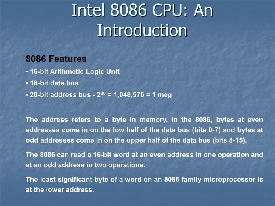
8086 Features
• 16-bit Arithmetic Logic Unit
• 16-bit data bus
• 20-bit address bus - 220 = 1,048,576 = 1 meg
The address refers to a byte in memory. In the 8086, bytes at even
addresses come in on the low half of the data bus (bits 0-7) and bytes at
odd addresses come in on the upper half of the data bus (bits 8-15).
The 8086 can read a 16-bit word at an even address in one operation and
at an odd address in two operations.
The least significant byte of a word on an 8086 family microprocessor is
at the lower address.
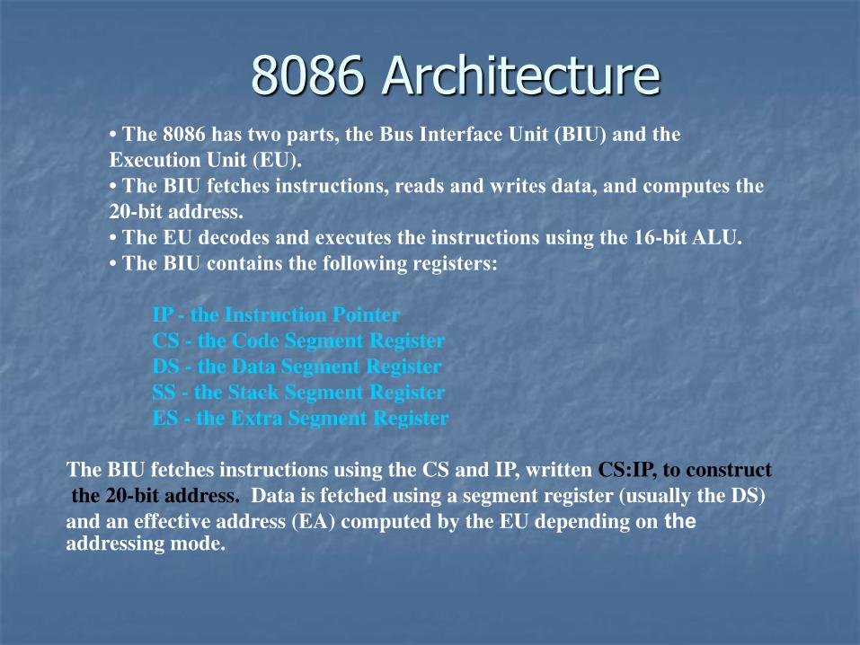
8086 Architecture • The 8086 has two parts, the Bus Interface Unit (BIU) and the Execution Unit (EU).
• The BIU fetches instructions, reads and writes data, and computes the 20-bit address.
• The EU decodes and executes the instructions using the 16-bit ALU.
• The BIU contains the following registers:
IP - the Instruction Pointer
CS - the Code Segment Register
DS - the Data Segment Register
SS - the Stack Segment Register
ES - the Extra Segment Register
The BIU fetches instructions using the CS and IP, written CS:IP, to construct
the 20-bit address. Data is fetched using a segment register (usually the DS)
and an effective address (EA) computed by the EU depending on the addressing mode.
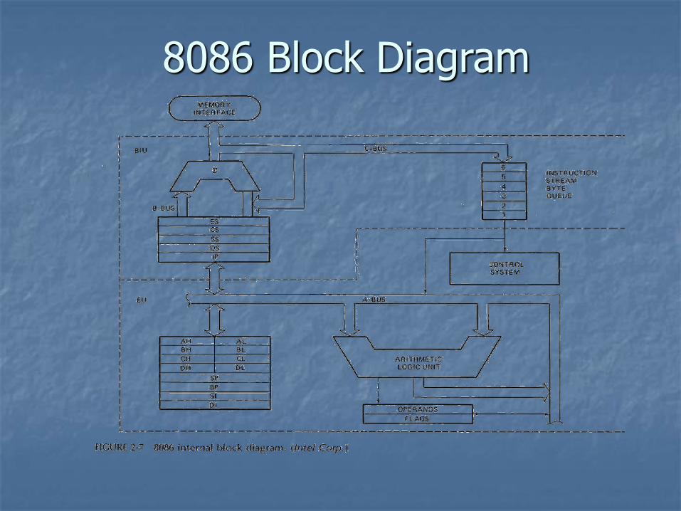
8086 Block Diagram
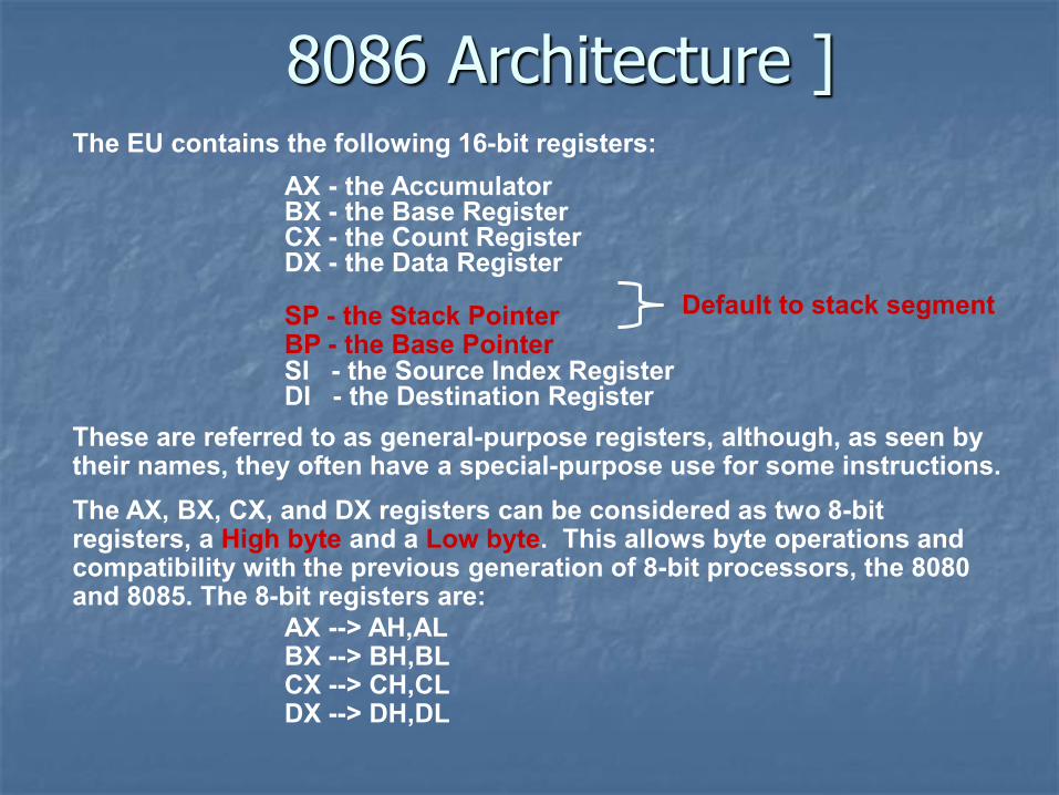
The EU contains the following 16-bit registers:
AX - the Accumulator BX - the Base Register CX - the Count Register DX - the Data Register SP - the Stack Pointer
BP - the Base Pointer SI - the Source Index Register DI - the Destination Register
These are referred to as general-purpose registers, although, as seen by their names, they often have a special-purpose use for some instructions.
The AX, BX, CX, and DX registers can be considered as two 8-bit registers, a High byte and a Low byte. This allows byte operations and compatibility with the previous generation of 8-bit processors, the 8080 and 8085. The 8-bit registers are:
AX --> AH,AL BX --> BH,BL CX --> CH,CL DX --> DH,DL
8086 Architecture ]
Default to stack segment
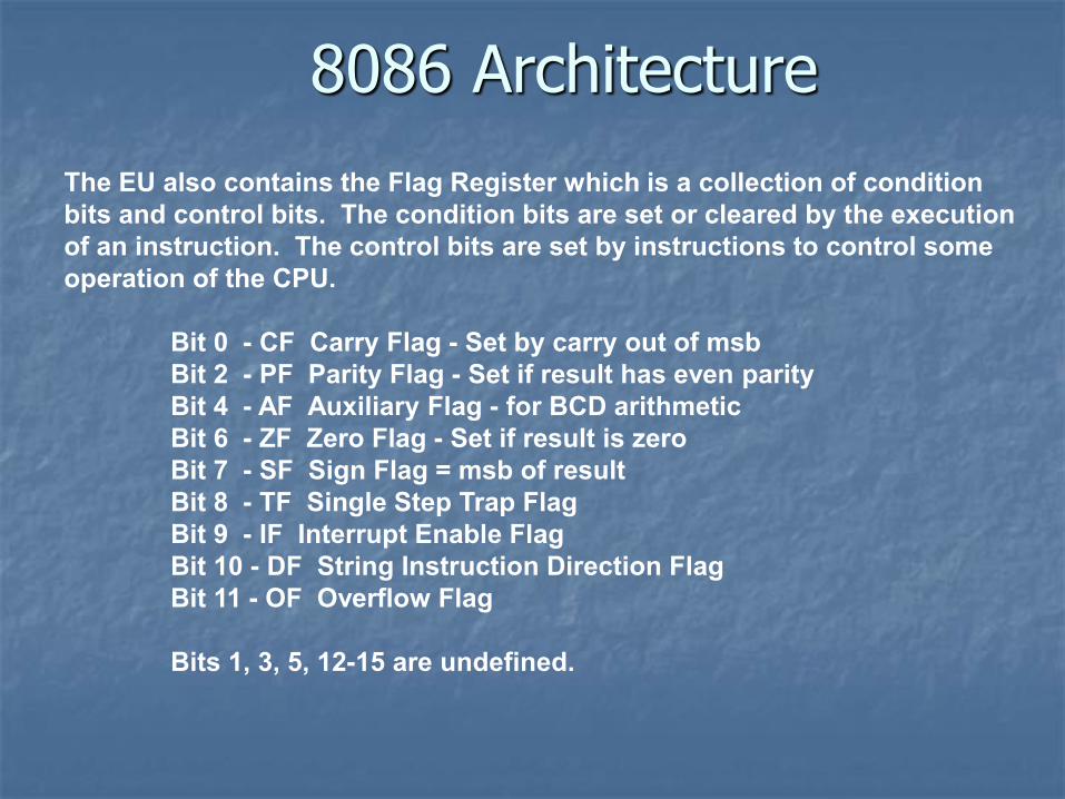
8086 Architecture The EU also contains the Flag Register which is a collection of condition bits and control bits. The condition bits are set or cleared by the execution of an instruction. The control bits are set by instructions to control some operation of the CPU.
Bit 0 - CF Carry Flag - Set by carry out of msb Bit 2 - PF Parity Flag - Set if result has even parity Bit 4 - AF Auxiliary Flag - for BCD arithmetic Bit 6 - ZF Zero Flag - Set if result is zero Bit 7 - SF Sign Flag = msb of result Bit 8 - TF Single Step Trap Flag Bit 9 - IF Interrupt Enable Flag Bit 10 - DF String Instruction Direction Flag Bit 11 - OF Overflow Flag
Bits 1, 3, 5, 12-15 are undefined.
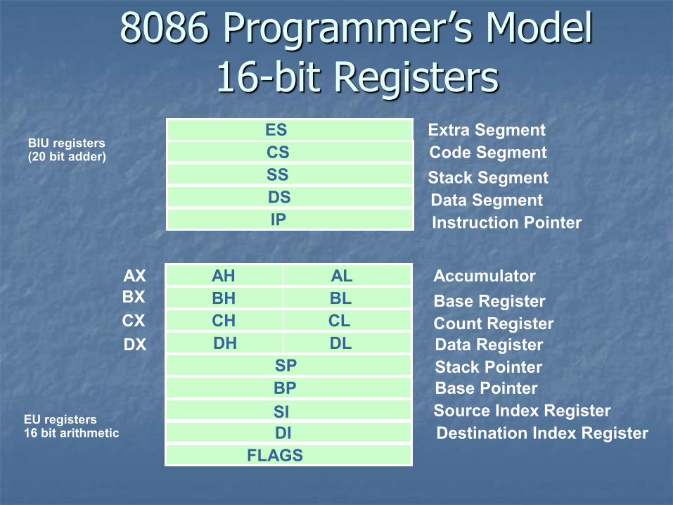
8086 Programmer’s Model 16-bit Registers
ES
CS
SS
DS
IP
AH
BH
CH
DH
AL
BL
CL
DL
SP
BP
SI
DI
FLAGS
AX
BX
CX
DX
Extra Segment
Code Segment
Stack Segment
Data Segment
Instruction Pointer
Accumulator
Base Register
Count Register
Data Register
Stack Pointer
Base Pointer
Source Index Register
Destination Index Register
BIU registers (20 bit adder)
EU registers 16 bit arithmetic
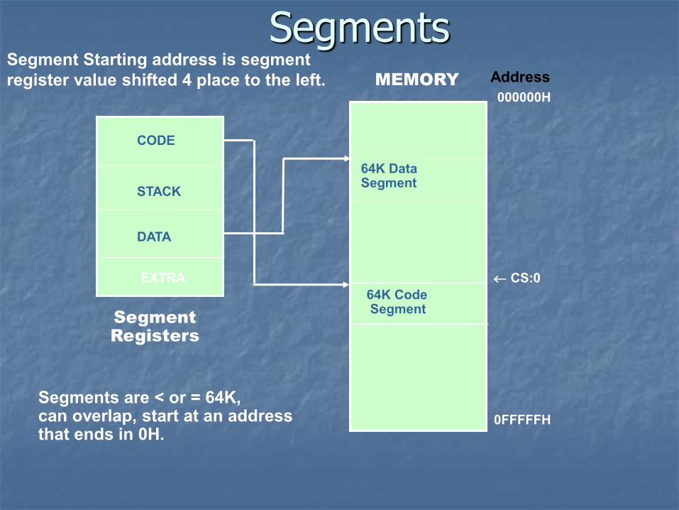
Segments
Segment Registers
EXTRA
64K Data Segment
64K Code Segment
CODE
STACK
DATA
MEMORY Address
000000H
0FFFFFH
Segments are < or = 64K, can overlap, start at an address that ends in 0H.
CS:0
Segment Starting address is segment register value shifted 4 place to the left.
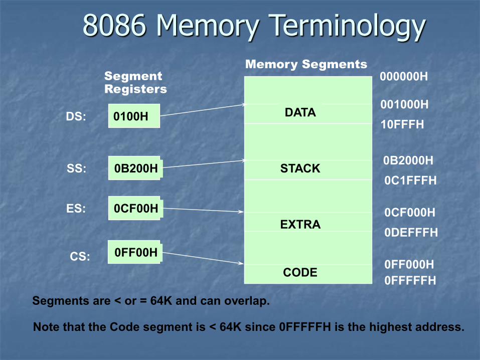
8086 Memory Terminology
CODE
DATA
STACK
EXTRA
0100H
0B200H
0CF00H
0FF00H
DS:
SS:
ES:
CS:
001000H
0B2000H
0CF000H
0FF000H
10FFFH
0C1FFFH
0DEFFFH
0FFFFFH
000000H Segment Registers
Memory Segments
Segments are < or = 64K and can overlap.
Note that the Code segment is < 64K since 0FFFFFH is the highest address.
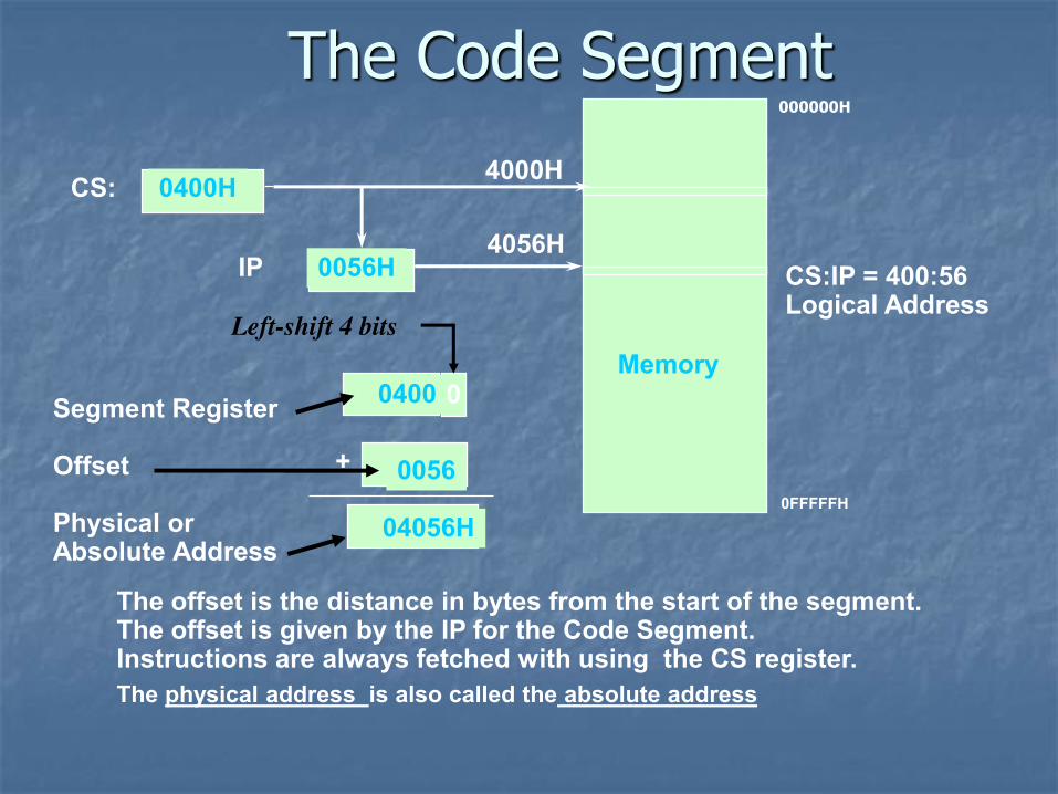
The Code Segment
The offset is the distance in bytes from the start of the segment. The offset is given by the IP for the Code Segment. Instructions are always fetched with using the CS register.
The physical address is also called the absolute address
000000H
Memory
Segment Register Offset Physical or Absolute Address
0
+
CS:
IP
0400H
0056H
4000H
4056H
0400
0056
04056H
CS:IP = 400:56 Logical Address
0FFFFFH
Left-shift 4 bits
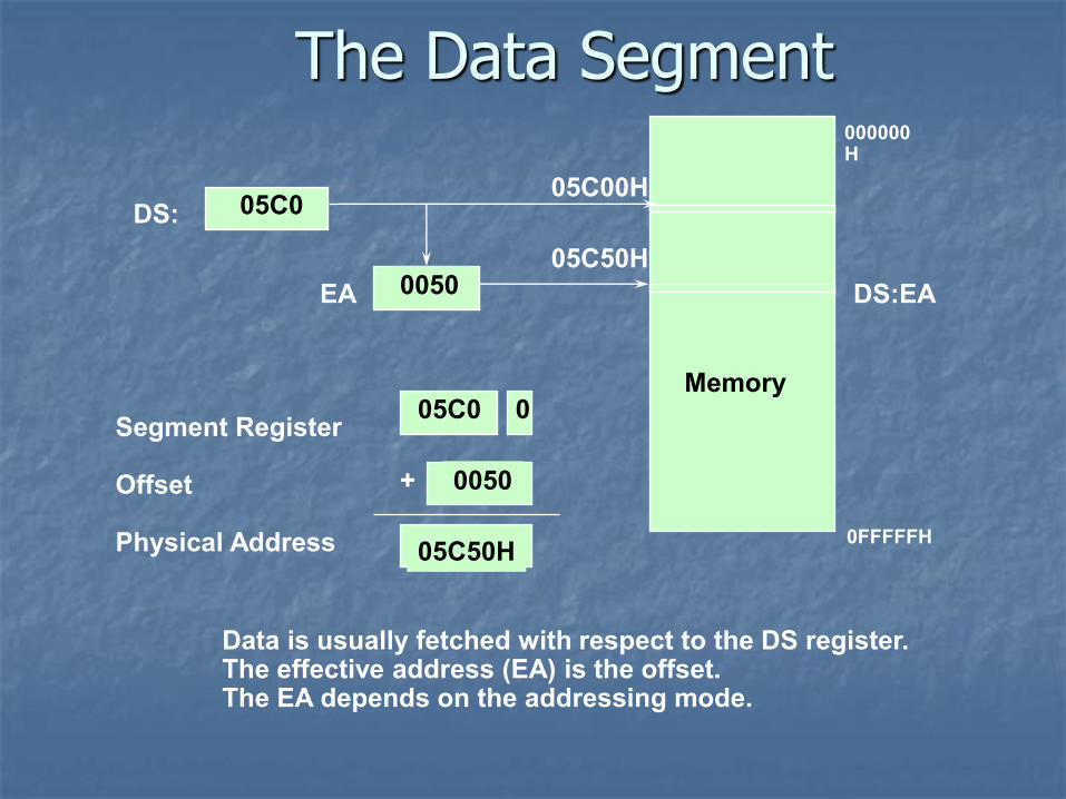
The Data Segment
Data is usually fetched with respect to the DS register. The effective address (EA) is the offset. The EA depends on the addressing mode.
Memory
Segment Register Offset Physical Address
+
DS:
EA
05C0
0050
05C00H
05C50H
05C0 0
0050
05C50H
DS:EA
000000H
0FFFFFH
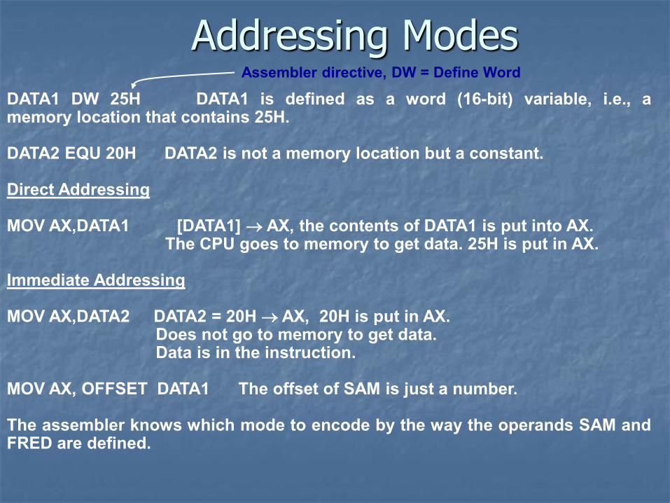
Addressing Modes
DATA1 DW 25H DATA1 is defined as a word (16-bit) variable, i.e., a memory location that contains 25H. DATA2 EQU 20H DATA2 is not a memory location but a constant. Direct Addressing MOV AX,DATA1 [DATA1] AX, the contents of DATA1 is put into AX. The CPU goes to memory to get data. 25H is put in AX. Immediate Addressing MOV AX,DATA2 DATA2 = 20H AX, 20H is put in AX. Does not go to memory to get data. Data is in the instruction. MOV AX, OFFSET DATA1 The offset of SAM is just a number. The assembler knows which mode to encode by the way the operands SAM and FRED are defined.
Assembler directive, DW = Define Word
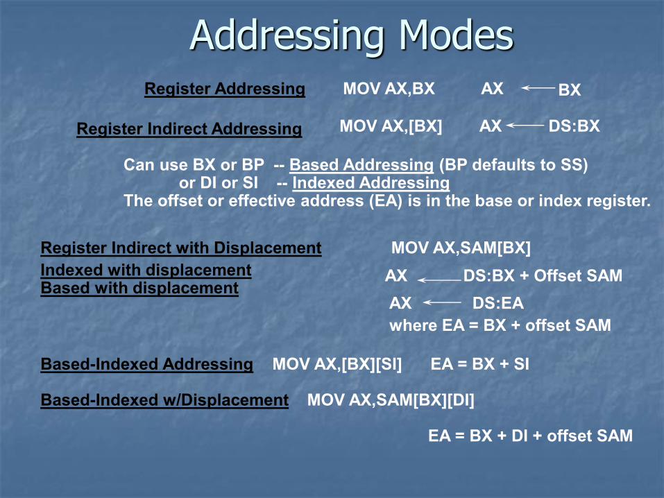
Addressing Modes Register Addressing MOV AX,BX AX BX
Register Indirect Addressing MOV AX,[BX] AX DS:BX
Can use BX or BP -- Based Addressing (BP defaults to SS) or DI or SI -- Indexed Addressing The offset or effective address (EA) is in the base or index register. Register Indirect with Displacement MOV AX,SAM[BX]
AX DS:BX + Offset SAM Indexed with displacement Based with displacement
Based-Indexed Addressing MOV AX,[BX][SI] EA = BX + SI Based-Indexed w/Displacement MOV AX,SAM[BX][DI] EA = BX + DI + offset SAM
AX DS:EA
where EA = BX + offset SAM
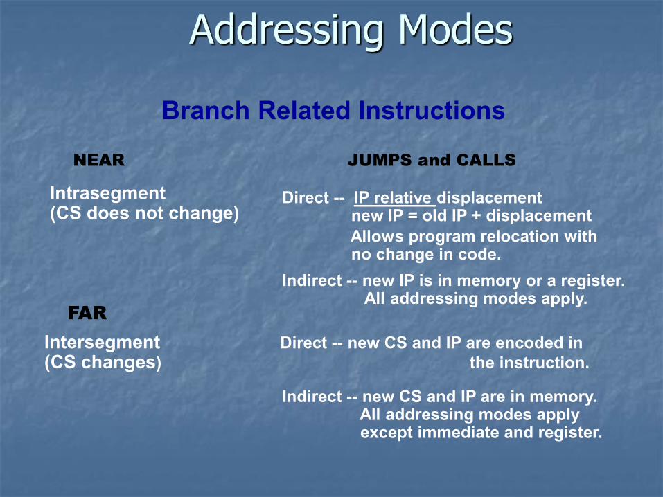
Addressing Modes
Branch Related Instructions
Intrasegment (CS does not change)
Direct -- IP relative displacement new IP = old IP + displacement
Allows program relocation with no change in code.
Indirect -- new IP is in memory or a register. All addressing modes apply.
Intersegment Direct -- new CS and IP are encoded in (CS changes) the instruction.
Indirect -- new CS and IP are in memory. All addressing modes apply except immediate and register.
NEAR JUMPS and CALLS
FAR
Assembly Language
The Assembler is a program that reads the source program as data and translates the instructions into binary machine code. The assembler outputs a listing of the addresses and machine code along with the source code and a binary file (object file) with the machine code. Most assemblers scan the source code twice -- called a two-pass assembler.
• The first pass determines the locations of the labels or identifiers. • The second pass generates the code.
Assembly Language To locate the labels, the assembler has a location counter. This counts the number of bytes required by each instruction.
• When the program starts a segment, the location counter is zero. • If a previous segment is re-entered, the counter resumes the count. • The location counter can be set to any offset by the ORG directive.
In the first pass, the assembler uses the location counter to construct a symbol table which contains the offsets or values of the various labels. The offsets are used in the second pass to generate operand addresses.
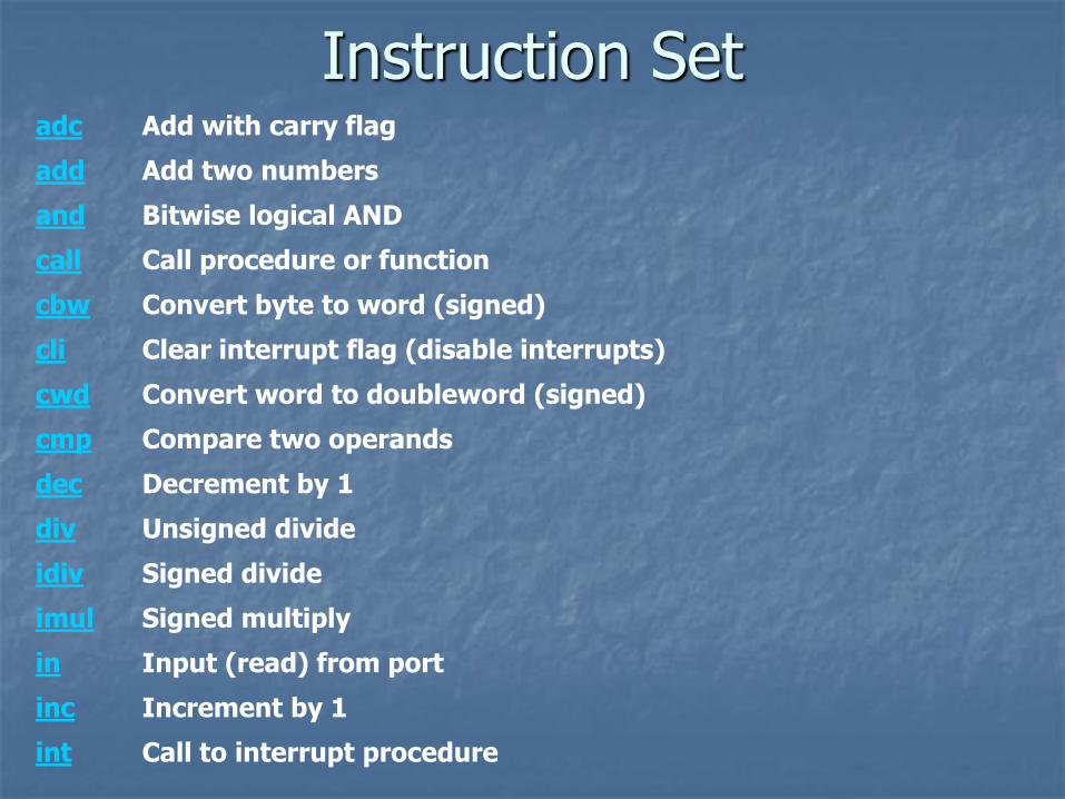
adc Add with carry flag
add Add two numbers
and Bitwise logical AND
call Call procedure or function
cbw Convert byte to word (signed)
cli Clear interrupt flag (disable interrupts)
cwd Convert word to doubleword (signed)
cmp Compare two operands
dec Decrement by 1
div Unsigned divide
idiv Signed divide
imul Signed multiply
in Input (read) from port
inc Increment by 1
int Call to interrupt procedure
Instruction Set
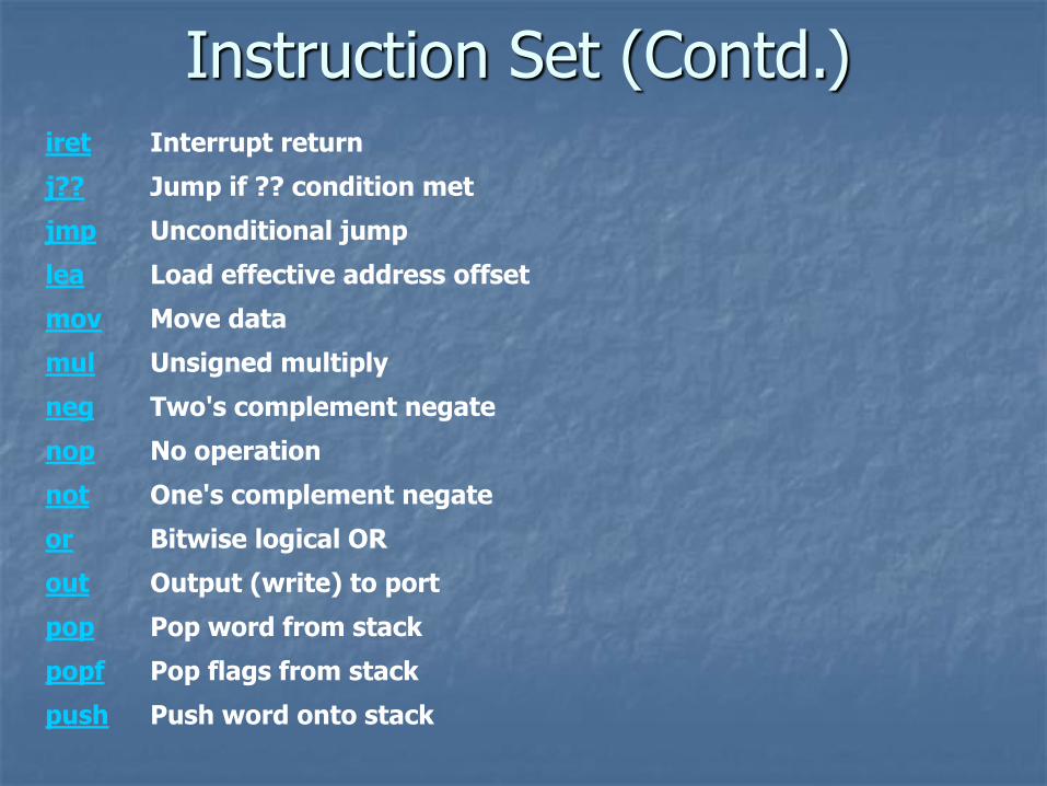
iret Interrupt return
j?? Jump if ?? condition met
jmp Unconditional jump
lea Load effective address offset
mov Move data
mul Unsigned multiply
neg Two's complement negate
nop No operation
not One's complement negate
or Bitwise logical OR
out Output (write) to port
pop Pop word from stack
popf Pop flags from stack
push Push word onto stack
Instruction Set (Contd.)
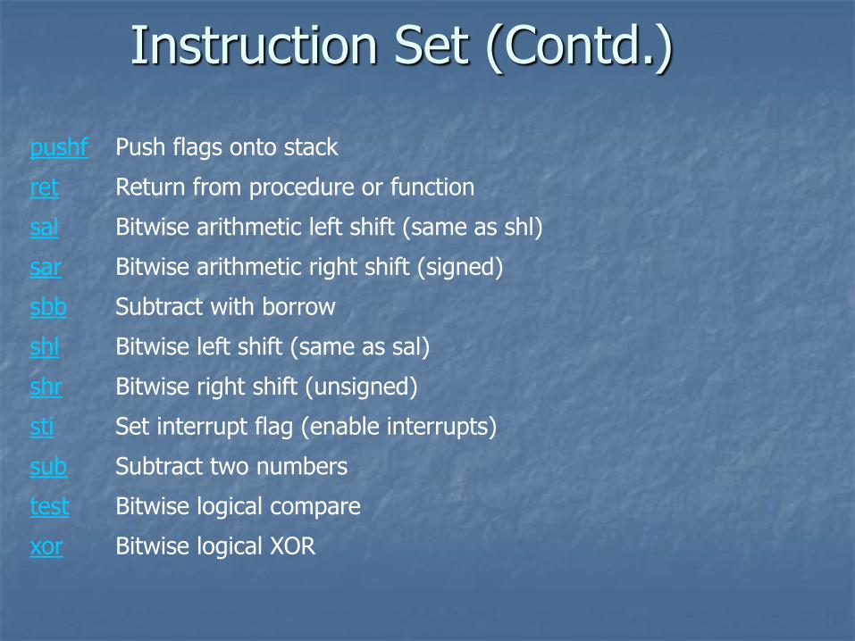
pushf Push flags onto stack
ret Return from procedure or function
sal Bitwise arithmetic left shift (same as shl)
sar Bitwise arithmetic right shift (signed)
sbb Subtract with borrow
shl Bitwise left shift (same as sal)
shr Bitwise right shift (unsigned)
sti Set interrupt flag (enable interrupts)
sub Subtract two numbers
test Bitwise logical compare
xor Bitwise logical XOR
Instruction Set (Contd.)
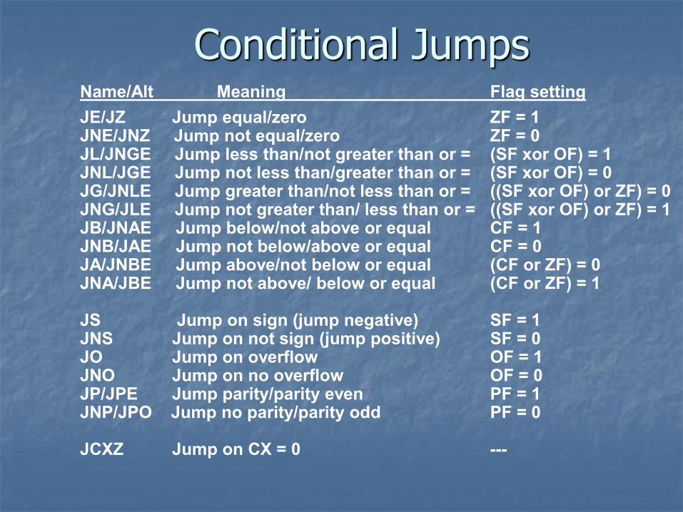
Conditional Jumps Name/Alt Meaning Flag setting
JE/JZ Jump equal/zero ZF = 1 JNE/JNZ Jump not equal/zero ZF = 0 JL/JNGE Jump less than/not greater than or = (SF xor OF) = 1 JNL/JGE Jump not less than/greater than or = (SF xor OF) = 0 JG/JNLE Jump greater than/not less than or = ((SF xor OF) or ZF) = 0 JNG/JLE Jump not greater than/ less than or = ((SF xor OF) or ZF) = 1 JB/JNAE Jump below/not above or equal CF = 1 JNB/JAE Jump not below/above or equal CF = 0 JA/JNBE Jump above/not below or equal (CF or ZF) = 0 JNA/JBE Jump not above/ below or equal (CF or ZF) = 1 JS Jump on sign (jump negative) SF = 1 JNS Jump on not sign (jump positive) SF = 0 JO Jump on overflow OF = 1 JNO Jump on no overflow OF = 0 JP/JPE Jump parity/parity even PF = 1 JNP/JPO Jump no parity/parity odd PF = 0 JCXZ Jump on CX = 0 ---
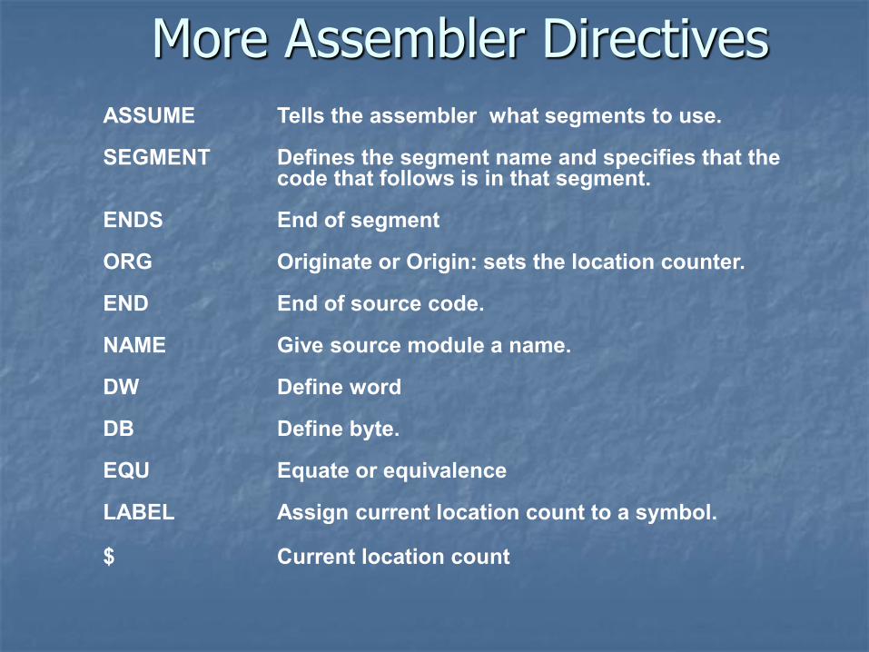
More Assembler Directives
ASSUME Tells the assembler what segments to use. SEGMENT Defines the segment name and specifies that the
code that follows is in that segment. ENDS End of segment ORG Originate or Origin: sets the location counter. END End of source code. NAME Give source module a name. DW Define word DB Define byte. EQU Equate or equivalence LABEL Assign current location count to a symbol. $ Current location count