Integrity Bath€¦ · 2071 14th Ave – Columbus, NE 68601 800-798-5867 FAX: 402-563-9102...
18
Form MB80MN11 Rev 0001 - 07-27-2015 2071 14 th Ave – Columbus, NE 68601 800-798-5867 FAX: 402-563-9102 www.mastercarebath.com Integrity Bath Model MB-80-R Installation Manual (Specifications & Rough-In Included) Important Safety Instructions Read & Follow All Instructions Thoroughly
Transcript of Integrity Bath€¦ · 2071 14th Ave – Columbus, NE 68601 800-798-5867 FAX: 402-563-9102...

Form MB80MN11 Rev 0001 - 07-27-2015
2071 14th Ave – Columbus, NE 68601
800-798-5867 FAX: 402-563-9102 www.mastercarebath.com
Integrity Bath Model MB-80-R
Installation Manual (Specifications & Rough-In Included)
Important Safety Instructions Read & Follow All Instructions Thoroughly


Integrity Bath
Standard Tub Models MB-80 Console Tub Models MB-80-R
Dimensions: Bath: Width: Standard (MB-80) 34 ½”
Width: Console (MB-80-R) 52 ½” Length: Standard (MB-80) 70” Length: Tub/Console (MB-80-R) 79” Tub Rim Height: (All Models) 36 ½” Console Height: Console (MB-80-R) 68”
Specifications: Back Flow Prevention: 1”Air gap for tub fill, vacuum breakers for MB-80-R shower hoses. Watts N-9 double checks for MB-80
shower hoses. Note: The factory provided backflow prevention is the most widely accepted. Local codes may require changes, which is the responsibility of the local plumbing contractor.
BathAire(SM)
Outlets: 5 with 6 ports each for a total 30 warm air massage outlets.Door Seal: Seal certified by Warnock Hersey to the ASME A112.19.15-2005 and ASTM D 2000 standards to insure long
lasting durability for bathtubs with pressure sealed doors. Highly resistant to oils, detergents and all water conditions.
Electrical: UL/CSA approved 120V AC, 60 Hz, 15 Amp dead front GFCI (ground fault circuit interrupter)
Installation Time: 1 ½ hours Inspection and Adjustments: ½ hour Liquids Storage: Located behind lockable service access doors. Motor Specs: BathAire(SM) Motor: 120 V., 11 Amps, 1.3 H.P. Variable speed with built-in 600 watt heating element for
maximum comfort and control. Patent: US 6,766,543 B1.Room Size: Standard Model 6’ wide x 9’4” long; Console model 6’ wide x 10’ long. Can fit in smaller room; call
with dimensions. Service Access: Controlled access through lockable service doors. Electrical Standards: CAN/CSA C22.2 No. 218.2-93 (R2004) Hydromassage Bathtub Appliances.
UL 1795 Hydromassage Bathtubs, Third Edition, Including revisions through to Sept. 22, 2006. Plumbing Standards: Warnock Hersey, CSA B45.5 (2008); ASME A112.19.15 (2005); CSA B45S1 (2004); ANSI Z124.1.2 (2005). State Standards: IL Dept. of Public Health, Product approval letter dated 10/28/04.
Commonwealth of Massachusetts, Approval Code P3-1108-235 Michigan State Code Commission, Certificate of Acceptability No. 1554 PA. Wisconsin Administrative Code, In Compliance with chapters Comm. 82 through 84, Wis. Adm. Code, and Chapters 145-160, Wisconsin Statutes. Product File #20060062 & 20010143.
Establishment Registration: 30033336913Switches: Membrane Thermometer: Analog or digital temperature measurements. Tub Entry: Door counter-balanced with simple guidance system for ease of operation. Tub Fill/Shower: Built-in thermostatic mixing valve certified to ASSE 1016-2005, AMSE A112.18.1-2005, CSA B125, and UPC
listed. Tub Fill / Shower shut off valves certified ASSE and UPC listed with ceramic disc controls. Tub Shell: Sanitary gel-coated FRP (Fiberglass Reinforced Polymer). Tub Water Use: 55 gallons Minimum with normal displacement 4 inches below over flow escutcheon. Waste: 2" PVC schedule 40 pipe. Water Connection: ¾” hose swivel connections supplied by manufacturer Water Supply: ¾” hot and cold with shut-offs. Hot and cold water pressure 45 psi. Hot water temperature to be 120o F and
Cold water to be 59o F.Weight: MB-80 (420 lbs), MB-80-R (Tub 385 lbs, Console 240 lbs), MT-80 Transfer system (150 lbs).
Approximately 10 years--determined by use and conditions45 gallon fill capacity
Warning: 1) Risk of electrical shock; Disconnect electric power source before installation and subsequent servicing. 2) An equipmentgrounding terminal is provided in the field wiring compartment. To reduce the risk of electrical shock, this terminal must be connected tothe grounding means provided in the electric supply panel with a conductor equivalent in size to the circuit conductors supplying this equipment. 3) Install this unit in accordance with the U.S. National Electrical Code in the U.S.A and the Canadian Electrical Code, Part I in Canada.
10-30-14 Page 2 of 16
2071 14th Ave. Columbus, NE 68601 Ph: 800-798-5867Fax: 402-564-9102 Web: mastercarebath.com
Useful Life: Reservoir:
MB-80-R Integrity Bath ______________________________________________________________________________________________
MasterCare Patient EquipmentNote: Integrity Bath must be purchased or specified with the Integrity Transfer Chair. For more information please
contact MasterCare.
CUSTSERV
Highlight
CUSTSERV
Highlight

MB-80-R Integrity Bath ______________________________________________________________________________________________
10-30-14 Page 3 of 16
1. Plan Bathing System Layout
FIG. # 1 Right Hinged Door
RoomDoor
130 "
112 "
1
O4
"
85
3/4
"
4
5"
5
1"
40
3/4
”
31"
Outside lines represent the recommended area for optimum operational access.
Inside line s represent the minimum area for in stallation with room door positioned as shown to open outward.
See
plu
mb
ing
note
s ne
xt p
age
rega
rdin
g flo
or d
rain
.
FIG. # 2 Left Hinged Door
RoomDoor
: CAUTION
130 "
112 "
1
O4
"
85
3/4
”
4
0 3
/4"
45
"
51
"
Outside lines represent the recommended area for optimum operational access.
Inside line s represent the minimum area for in stallation with room door positioned as shown to open outward.
See
plum
bing
not
es
next
pag
e re
gard
ing
floor
dra
in.
Warning:
Choose flattest floor location. Make sure sufficient room is provided to allow unobstructed area for transfer in and out of the tub with the transfer system. Room dimensions, door sizes and floor drain placement, must comply with all applicable building and health codes.
Caution:
Figure #1 and #2 tub placement is critical for door opening and access to disinfectant and dispensing both sides. Space around system is needed to allow assistant to access resident, disinfectant & dispensing systems and maintain both sides. Avoid covering switches, valves and other items that must be accessed by authorized personnel or maintenance.
TUB
CABINET
CONSOLE
CORRECT FLOOR SURFACE
CHAIR TRANSFER SYSTEM
CORRECT FLOOR DRAIN LOCATION
INCORRECT INCLINEDFLOOR SURFACE
INCORRECT DRAINLOCATION IN FRONT OF TUB
FIG. # 4
Floor Surface: Correct & Incorrect
FIG: # 3

MB-80-R Integrity Bath ______________________________________________________________________________________________
10-30-14 Page 4 of 16
2. Mark Tub Center Line On Wall & Floor
FIG. # 1
Bathing SystemFootprint
Allow Minimum 33" For Door Arc
CenterLine Of Tub
33 1/2"
52 1/2"
33"
26"
76 1/2"
3. Install Electrical Service
FIG. # 2
25”
10” Center
Line Of Tub
Floor
Wall
4. Install Plumbing Service
FIG. # 3
Floor
Wall5" Facets or ball
valves with 3/4"hose connectors
"2" PVC Waste Pipe
5"18"
3" +/- 1/4 "
Electrical Service Notes
WARNING: Electrical current can cause severe injury or death if the following precautions are not heeded.WARNING: Turn off power source.WARNING: Lock circuit open to prevent accidental activation.WARNING: Electrical service must be located higher than plumbing service.WARNING: Electrical switches and outlets must not be in reach by bathers in the tub.WARNING: Electrical wiring must comply with all applicable codes. A licensed electrician may be required to install the service.WARNING: Connect the bathing system ONLY to a circuit protected by a CLASS A GFCI.WARNING: Connect only to a branch circuit protected by an over current protection device rated not more than 15 amps.
Plumbing Service Notes
It is strongly recommended that a floor drain be installed in the vicinity of the front of the tub 40” either side of the centerline of the tub. Plumbing service must comply with all applicable building and plumbing codes. A licensed plumber may be required to install this service. Local plumbing codes may require back flow prevents to be installed on both the hot and cold water lines.
General Notes Caution: Wall and floor openings for the electrical and plumbing service installations should be closed and sealed to help maintain sanitary conditions.
Memo: “P” Trap to be supplied by customer not manufacturer.
Floor
Alternate # 1 Alternate # 2 Wall
2" Waste Pipe With Trap
Approx. 27 "
To TubDrain
Approx. 27 "
To TubDrain
Floor
Wall
2" Waste Pipe With Trap
3"+/- 1/4"
3"+/- 1/4"
FIG. # 4
NOTE: Item 4-Install Plumbing Service The height of the PVC waste pipe should be 3"
All dimensions are approximate + / - 1/4"
CAUTION: The tub uses flexible hoses--it is an industry standard and is recommended by MasterCare to replace the hoses every five (5) years and to inspect the hoses yearly for any obvious signs of damage, wear, etc. If any signs of damage or wear are noted replace the hoses.
120V AC, 60 Hz, 15 Amp CLASS A GFCI receptacle flush mounted in wallWARNING: Connect the bathing system ONLY to a circuit protected by a CLASS A GFCI
CUSTSERV
Highlight
CUSTSERV
Highlight
CUSTSERV
Highlight

MB-80-R Integrity Bath ______________________________________________________________________________________________
10-30-14 Page 5 of 16
BATHING SYSTEM INSTALLATION
General Warnings:
Warning: Risk of electrical shock.
All equipment comes standard with a 120V – 3 prong electrical plug. Plug the bathing system into a 120V AC, 60 Hz, 15 Amp CLASS A GFCI receptacle. All hard wiring must be performed by a licensed electrician following local codes. The main power supply must be disconnected before hard wiring. Warning!! Failure to disconnect main power before hard wiring unit can result in Electrical Shock, Death or Damage to Equipment not covered with the warranty.
An equipment grounding terminal is provided in the field wiring compartment (electrical box on the unit). To reduce the risk of electrical shock, this terminal must be connected to the grounding means provided in the electrical supply panel with a conductor equivalent in size to circuit conductors supplying this equipment.
Install this unit in accordance with the Canadian electrical code, part I, in Canada and in accordance with the U.S. national electrical code in the U.S.A. or local codes whichever applies.
Warning: Risk of Scalding.
Hot water can scald people. Temperature control valve must be adjusted before using bath. Do not allow temperature to exceed 109.4 F (43 C)
Other Precautions:
Tub and cabinet components are heavy and bulky. Do not attempt to lift or move this tub or cabinet alone.
Damp or wet floors can be slippery causing falls and serious injury. Dry wet areas before starting to install bathing system.
Standing in tub can damage the tub or lead to falls and serious injury. Do not stand in tub during installation or use. Do not allow residents to stand in the tub.
1. Check Electrical and Plumbing and Service Rough-Ins
Bathing system location identified and marked per instructions in rough-ins Plumbing installed according to instructions in rough-in manual. Wall and floor openings around pipes closed and sealed.
2. Clear Waste Water Drain
Make sure wastewater drain is free of debris
3. Flush Debris from Hot and Cold Water Service Lines
Flush debris from the incoming hot and cold water lines. Run about 10 gallons through each line into a bucket. This will protect the plumbing valves in the bathing system from potential damage by migration of debris into its vital components.
You are now ready to install your MasterCare Integrity Bathing System.
4. Position Tub
Slide back of tub towards the wall so that top edge is squared off 9” (23.9cm) from wall. Remove dispensing and disinfectant boxes by removing the 2 screws at the top of the boxes then lift and set them to the side of the door opening.
Make sure 2” drain on tub is aligned with 2” drain rough-in. Connect with 2” flexible connector, don’t tighten yet. Note: If flexible connector doesn’t meet local codes use any type of detachable coupler that meets code to allow drain connection to be uncoupled so tub can slid forward for service.
Anchor bolt holelocation.
9”
2" (5 cm) Connector
FIG. # 1
CAUTION: The tub uses flexible hoses--it is an industry standard and is recommended by MasterCare to replace the hoses every five (5) years and to inspect the hoses yearly for any obvious signs of damage, wear, etc. If any signs of damage or wear are noted replace the hoses.
CUSTSERV
Highlight

MB-80-R Integrity Bath ______________________________________________________________________________________________
10-30-14 Page 6 of 16
5. Locate & Set Anchors In Floor
Find the two 1/4” holes located in the fiberglass rear floor area of the tub. Mark the hole locations on the floor, disconnect the 2” drain and slide the tub forward about six feet. Drill two 1/2” holes for the 1/4” SS anchor bolt anchors. Clean/blow out the holes that were previously drilled. Slide the tub back, connect the drain and set the anchors accordingly.
Caution: During next step be careful not to scratchtop or sides of tub while sliding tub inside the cabinet.
6. Pre-Position Reservoir
Position the Reservoir (see figure #1) centered on the two inch drain. Leave about 40” between the reservoir support cabinets and wall for access purposes. Connect hot/ cold water high pressure hoses from inside of the support cabinets to the hot and cold water supply valves with ¾” male hose fittings.
FIG. # 1
40”
7. Reset Tub
Slide tub back inside of reservoir side service cabinets to 9” square with the wall. Then remove the disinfectant and oil/shampoo dispensing boxes and set aside. Align predrilled anchor holes in rear floor of tub with anchors already set in the floor. Secure with anchor bolts.
8. Level Tub
Shim with floor tile as needed to level tub (see FIG. # 2 this page).
Warning:
If shimming to level tub is necessary because of unlevel floor, use non-porous material such as floor tile. If shimming ¾” high or more contact MasterCare representative for riser kit to increase the height of carrier for positive tub/chair latch connection. Transfer chair could drop to floor if tub and carrier rails are not correctly aligned. Tub must be level to facilitate alignment of lower carrier rails to tub rails.
9. Make Final Connections
Connect the 2” tub drain to 2” drain rough-in. Replace the dispensing boxes on both sides. Plug the bathing system into a 120V AC, 60 Hz, 15 Amp CLASS A GFCI receptacle. Connect the remaining hot water supply hose to the ¾” upper male hose fitting at the inside top of the disinfectant supply cabinet.
10. Tighten Anchor Bolts
Re-install dispensing boxes
11. Position Reservoir Against Wall
Remove any obstructions that would interfere with the fit of the console against the wall. If needed trim the back edge of the lower reservoir supports on each side to fit around the mop board or cut the mop board to butt against them. Carefully slide reservoir over tub all the way back so that it is firmly against the wall. The trim seal bulb on the
back edge should be slightly compressed.
12. Connect Disinfectant Shower Wand Hose
Connect ½” female end of the disinfectant hose to the ½” lower male fitting on the inside top of the disinfectant box.
Shim to level
FIG. # 2

MB-80-R Integrity Bath ______________________________________________________________________________________________
10-30-14 Page 7 of 16
VERIFY SYSTEM OPERATION
13. Close and Lock Door
Reference the copy of wall chart instructions, page 14, as needed during the verification process. Rotate and position door inside the tub as far as it will go. Wide both hands push door down carefully until it latches in the down position. Rotate door camarm up into full locked position.
14. Turn on BathAire
Turn on BathAire by pushing the “BathAireOn/Off” button.
15. Turn on Supply Water
Turn on the hot and cold water supply valves. With the shower wand pointed inside the tub turn the chrome shower spray on/off handle counter clockwise (on) purge the plumbing system of any trapped air. Turn off after trapped air is purged. Rotate the reservoir open/closed handle on side of the console to open position. Rotate chrome reservoir fill knob on plumbing control deck counter clockwise until full open.
16. Check for Connector Leaks
Check all hose connections for leaks. While holding shower wand over inside of tub turn chromeshower spray handle counter clockwise (on) and check for leaks. Turn shower spray off. While holding disinfectant wand over inside of tub turn chrome “disinfectant” handle counter clockwise (on) and check for leaks. Turn disinfectant handle clockwise (off). Tighten any loose connections that are leaking.
17. Check Fill Temp Gauge
Adjust temperature of the incoming water to approximately 102 F (39 C) by turning the mixingvalve handle to a position that provides a constant readout of desired temperature on the Thermometer located on the right side of the reservoir. Then turn the mixing valve handle to full hot.
Warning: Hot water can scald people.Temperature of the water in the tub must not exceed 109.4 F (43 C) or limit per facility policy whichever is less. If it does, call MasterCare’s Technical Service Department 1-800-798-5867 for assistance.
18. Fill Reservoir
Rotate the reservoir open/closed handle on side of the console to closed position. Continue to fill reservoir until completely full. A built-in float valve will automatically shut off the water when the reservoir is full. Check bath temp gauge, it should read approximately (within 3 degrees) what the fill temp. gauge read while filling the reservoir.
19. Check Reservoir Open/Close Function
Rotate reservoir open/close handle on the side of the console to the open position. Then rotate reservoir open/close handle on the side of the console to the closed position. Water flow from fill spigot should stop after a few seconds with some minor residual flow until all the water drains out of the plumbing system.
20. Fill Tub
Rotate reservoir open/close handle on the side of the console back to the open position. Water should flow freely from the reservoir into the tub. Fill time from reservoir to tub should be approximately 1 minute and 45 seconds under optimum conditions. Memo: Without a bather inside the tub to displace water the tub will only be partially filled.
21. Check BathAire Hydromassage Function
Air bubbles should flow evenly out of all aerators. The level of air flow was preset at the factory. Check all functions on the oval BathAire control panel per copy of the operational procedures wall chart on page 14 of this manual.
. 22. Drain Tub
Rotate Drain Open/Close lever to open position. Allow tub to drain completely. Check all drain connections for leaks. Make sure all water drains from tub. If not, tub is not level. Level per instructions on page 7.

MB-80-R Integrity Bath ______________________________________________________________________________________________
10-30-14 Page 8 of 16
FIG. # 1
23. Check & Adjust Disinfectant Dispensing System
Refer to the Operational Procedures (In the black binder sent with the tub) for the disinfectantdispensing system to set up and check this system to make sure it operates as intended.
With disinfectant wand pointed inside the tub turn chrome disinfectant “On/Off” handle counter clockwise all the way on.
The clear tubing line from the one gallon bottle of concentrated cleaner disinfectant should have solution all the way up. After a few seconds a soapy disinfectant solution will emit from the wand. See below for adjustments.
Caution: The Cleaner/Disinfectant system ispreset at the factory to dispense 2 oz. of concentrated disinfectant per gallon of water. Using other brand disinfectant cleaners or system replacement parts could cause this recommended ratio to change and result in an incorrect solution.
The flow rate of concentrate can be adjusted by turning the adjustment screw (see figure #1) on the injector housing counter clockwise for more, clockwise for less.
The adjustment screw can be accessed through the small plugged hole to the left of the disinfectant“On/Off” handle.
24. Check & Program Bath Oil & Shampoo Dispensing System
Remove the service access door on the right side of the tub. Connect the one gallon jugs of bath oil and shampoo shipped separately in the Starter Kit to the appropriate dispensing hoses. Bath oil left hose and Shampoo right hose. To prime, push the appropriate button for the solution you want to prime for seven seconds.
Refer to the Operational Procedures (In the black binder sent with the tub) for the Bath Oil & Shampoo dispensing system to set up and check the system to make sure it operates as intended. Set to dispense ½ oz. bath oil and ¼ oz shampoo.
If any problems are encountered in items 23 or 24 above, check the Maintenance Instructions included in the aforementioned Operating Instructions or call your local MasterCare Representative or MasterCare direct for technical service support.

MB-80-R Integrity Bath ______________________________________________________________________________________________
10-30-14 Page 9 of 16
CHAIR SYSTEM ADJUSTMENT
General Warnings:
Tub & Chair rails must align properly to prevent chair derailment and provide smooth transfer of the chair. Transfer system lower carrier must latch to avoid disengagement from tub. Transfer system lower carrier caster bumpers, docking pin horizontal and vertical, railmounting bar & bumpers and chair rails alignment must be checked and adjusted before use. Improper chair to tub transfer adjustment could allow residents to fall to the floor resulting in severe injury. Failure to heed these warnings could result in injury to the patient or operator.
1. Open Tub Door
MEMO: For model MB-80-R with built-in chair without lower carrier disregard the rest of this procedure. Do, however, check the function of the chair lock lever. Pull up on the lever and move and lock the chair into its four basic positions: front for transfers, all the way back for upright bathing and about ¾” back for reclined bathing. Seedrawing of chair features on page 13.
FIG # 1
Tub Door
2. Position Transfer System
FIG # 2
Tub RailsCarrier RailsUnder Chair
MB-80-R Integrity Bath ______________________________________________________________________________________________
10-30-14 Page 10 of 16
Side c ut-a-way view of la tch p in receiver wi th chai rla tch p in posi tioned prior to docking.
Latch Pin Receiver Latch
Pin
1
Side c ut-a-way view of la tch p in receiver wi th chai rla tch p in in in itia l engagementphase.
2
Side c ut-a-way v iew of la tch p in receiver wi th chai r la tch p in in fu l ly engagedposi tion.
3
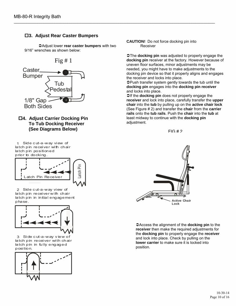
3. Adjust Rear Caster Bumpers
Adjust lower rear caster bumpers with two 9/16” wrenches as shown below:
Fig # 1
Tub Pedestal
CasterBumper
1/8" GapBoth Sides
4. Adjust Carrier Docking Pin To Tub Docking Receiver (See Diagrams Below)
CAUTION! Do not force docking pin into Receiver
The docking pin was adjusted to properly engage the docking pin receiver at the factory. However because of uneven floor surfaces, minor adjustments may be needed, you might have to make adjustments to the docking pin device so that it properly aligns and engages the receiver and locks into place. Push transfer system gently towards the tub until the docking pin engages into the docking pin receiver and locks into place. If the docking pin does not properly engage the receiver and lock into place, carefully transfer the upperchair into the tub by pulling up on the active chair lock(See Figure # 2) and transfer the chair from the carrierrails onto the tub rails. Push the chair into the tub at least midway to continue with the docking pin adjustment.
FIG # 2
Active Chair Lock
Access the alignment of the docking pin to the receiver then make the required adjustments for the docking pin to properly engage the receiver and lock into place. Check by pulling on the lower carrier to make sure it is locked into position.

MB-80-R Integrity Bath ______________________________________________________________________________________________
10-30-14 Page 11 of 16
4. (Continued)
The diagram below of the docking pin device will help you determine which nuts to loosen to make the required adjustments. Make sure tub is level per item # 8 page # 7 before making these adjustments. If the docking pin is too high or too low loosen the up/down adjustment nuts and adjust as needed. Tighten the nuts back down securely. Assess the alignment of the docking pin to the receiver then make the required adjustments for the docking pin to properly engage the receiver and lock into place.
FIG. # 1
TUB
Docking Pin
Docking Pin Receiver
Docking PinRelease Lever
Up/Down & Side to Side Adjustment Nuts
In/Out Adjustment Nuts
5. Center Rail Mounting Bars In The Door Opening and Adjust Mounting Bar Bumpers
With the carrier correctly latched to the tub, verify the mounting bars under the lower carrier rails have equal space between the mounting bars and the sides of the door opening. If not, loosen the side to side adjustment nuts on the docking pin and adjust as needed. Verify all docking pin assembly nuts and bolts are tight.
FIG. # 29/16" Nuts
BrakeUnlock TabDocking Pin
Release Lever Foot
Ramp9/16" Nuts
Bumper
Lower Carrier Rail
MountingBar
6. Align Lower Carrier Rails to Tub Rails
Position the lower carrier rails flush against the tub rails. Looking down from the top, the two lower carrierrails should align parallel with the tub rails. Looking from the side, the top of the two carrier rails should be 1/16” above the plain of the tub rails. See below:
FIG. # 3
Carrier Rail
17 7/16” Front RailTo Rail
Top View Unit Without Scale
Carrier & TubRails Must ButtAgainst Each Other
Rear Carrier RailsWidth DimensionMust Match TubRails Width
Carrier Rail
Tub Rail
Tub Rail
FIG. # 4
Carrier Rail
17 7/16” Front RailTo Rail
Top View Unit With Scale
Carrier & TubRails Must ButtAgainst Each Other
Rear Carrier RailsWidth Dimension1/16” Wider ThanTub Rails WidthEach Side
Carrier Rail
Tub Rail
Tub Rail
FIG. # 5
Carrier Raill
1/16" Side View
Tub Rail
To adjust, loosen the 9/16” nuts at the base of the lower carrier rails. See Figure # 2 on this page. Then make the required up/down and side to side adjustments to match the lower carrier rails to the tub rail. Tighten the nuts against each other when the desired adjustment is achieved.
MB-80-R Integrity Bath ______________________________________________________________________________________________
10-30-14 Page 12 of 16
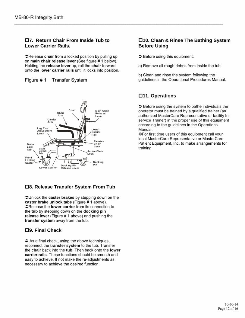
7. Return Chair From Inside Tub to Lower Carrier Rails.
Release chair from a locked position by pulling up on main chair release lever (See figure # 1 below). Holding the release lever up, roll the chair forward onto the lower carrier rails until it locks into position.
Figure # 1 Transfer System
BrakeUnlock Tab
BrakeLock Tab
LowerCarrierRail
Main ChairReleaseLever
Passive ChairLock
Act ive Chair Lock
Docking Pin
Carrier Arm
Chair Chair Arm
Leg RestAdjustmentLatch
Docking PinRelease LeverLower Carrier
FrontLocking Caster
8. Release Transfer System From Tub
Unlock the caster brakes by stepping down on the caster brake unlock tabs (Figure # 1 above). Release the lower carrier from its connection to the tub by stepping down on the docking pinrelease lever (Figure # 1 above) and pushing the transfer system away from the tub.
9. Final Check
As a final check, using the above techniques, reconnect the transfer system to the tub. Transfer the chair back into the tub. Then back onto the lowercarrier rails. These functions should be smooth and easy to achieve. If not make the re-adjustments as necessary to achieve the desired function.
10. Clean & Rinse The Bathing System Before Using
Before using this equipment:
a) Remove all rough debris from inside the tub.
b) Clean and rinse the system following theguidelines in the Operational Procedures Manual.
11. Operations
Before using the system to bathe individuals the operator must be trained by a qualified trainer (an authorized MasterCare Representative or facility In-service Trainer) in the proper use of this equipment according to the guidelines in the Operations Manual. For first time users of this equipment call your local MasterCare Representative or MasterCare Patient Equipment, Inc. to make arrangements for training

MB-80-R Integrity Bath ______________________________________________________________________________________________
10-30-14 Page 13 of 16
Door LatchRelease Button
Door Seal Open/Close Arm
Latch Pin Receiver Drain Open/
Close Lever
Oil/ShampooControl Panel
Mixing Valve
Reservoir Fill ValveOn/Off
Shower On/OffValve
Shower Wand
Reservoir
Disinfectant Wand
Disinfectant WandOn/OffValveBehind TheSide ServiceDoor
Bath WaterTemperature
FillTemperature
Tub FillLever
Service AccessDoorBath Oil Shampoo
Key Latch
GFCIReSet
AromaTherapyCap
Latch PinReceiver
Tub Rails
Auxiliary Drain Open/Close Lever
Auxiliary Drain Open/Close Lever
Tub DoorOpened
BrakeUnlock Tab
BrakeLock Tab
ChairRail
Main ChairReleaseLever
Passive ChairLock
Act ive Chair Lock
Latch Pin
Carrier Arm
Chair Chair Arm
Leg RestAdjustmentLatch
Latch PinRelease LeverLower Carrier
FrontLocking Castor
OPERATING INSTRUCTIONSMasterCare Bath Model MB-80-RIntegrity
1) Fill Reservoir:* Tub Fill Lever Shower Wand
Shower Control Valve Mixing ValveFill Temp Shower Control Valve Reservoir Fill Valve
2) Transfer Resident Into Tub:BathAire Control On/Off Button More & Less Air/Heat Buttons.Tub Door Chair Chair Rails Tub RailsChair Lower Carrier Latch Pin Receiver
Chair/Carrier Lower CarrierLocking Casters Brake Lock.
Active Chair Lock Locking Casters. Lower CarrierLatch Pin Release Lever,
Door Cam Arm
3) Before Filling The Tub From The Reservoir:
“Bath Temp”.
step # 6 Door Cam Arm
step #1
4) Fill Tub:Tub Fill Lever
Reservoir Fill Valve
5) To Use Shower Wand: step # 1
6) To Remove Resident From Tub: BathAire Leg Rest step # 2 Main Chair Release Lever Chair RailsLatch Pin Release Lever
Make sure the is turned to a full closed position. Make sure the is directed into tub. Turn the on. Adjust for desired safe water temperature (per facility policy) displayedon the bottom thermometer labeled “ ”. Turn off. Turn on. Continue monitoring to maintain desired temperature. Reservoir fill will shut off automatically when full.
* Push to turn on and adjust to desired speed using * Open . Back towards tub to align with .* Push back until is engaged in the (located in the lower front center of the
tub) and locks into position. Test by pulling on arms to make sure Lock front by stepping down on Adjust leg rest up one click by pulling up on leg rest.
* Pull up on , push chair into tub. Release Unlock from tub bystepping down on the push out-of-way. If tub has built-in chair, lock into front position, verify it islocked by pushing on it, then transfer resident into chair.
*Position door inside tub, push down until it latches and rotate up.
* Check bath temperature on the upper thermometer labeled Make sure the desired water temperature per facility policy is achieved (See warning # 1).
* If bath water exceeds desired temperatures, remove resident from bath per.. Close door and rotate up. Open drain. Drain
sufficient water from console to adjust temp to desire level per instructions in .
* After desired temp is verified, close drain and open and leave open until desired water level is achieved. Then close and fill for next bath, or turn off if no more baths are scheduled.
Follow procedure in above. Test on wrist before showering resident.
Open drain. After water is drained, turn off and open door. Adjust one click up. Align lower carrier to tub and engage per above, then lock the front casters. Pull up on
, then roll resident onto . (See warning # 2 below) Unlock front casters. Step down on to disengage carrier from tub to transfer resident. If tub has built-in chair, lock into front
position and transfer resident out using proper ergonomic techniques.
is locked into position.
7) To Clean/Sanitize Tub: Door Cam Arm
Disinfectant Wand
Reservoir Fill Valve Tub Fill Lever
Return chair to inside of tub. Close door and rotate up. Close drain. Rinse surfaces of tub & chair with shower wand. Apply MasterCare disinfectant cleaner with to all chair parts, inside tub surfaces and removed pads. Scrub with brush. Follow directions on disinfectant cleanerlabel. Rinse with hot water. At the end of the day, shut off
and drain reservoir completely. Leave in open position. Remove door seal, pads and belts for daily cleaning and sanitizing.
inside
On/Off
BathAireControl
MoreAir/Heat
LessAir/Heat
2 SpeedWave

Memo: 1) Local codes that require connection to a 4” sewer tap will be the responsibility of the purchasing entity.2) For electrical rough-ins use the same guidelines in the standard Integrity Rough-In Manual which thesespecial instructions were inserted in. 3) MasterCare’s bathing and showering systems are certified as meeting all national plumbing and electricalcodes. Local codes exceeding the requirements of the national codes are the responsibility of the purchasingentity.
MB-80-R Installation Manual(Specifications & Rough-In Included)
for MasterCare Shower Cabinets & Integrity Bath Systems With Built-In Toilet Feature
MasterCare
Rear View Of Integrity Tub 0r Shower Cabinet
Cut-A-Way Side View of Tub & Toilet Drain Detail Integrity Tubs With (See Memo Below) & Without Reservoir 0r Shower Cabinet
2” SCH 40 PVC Drain Pipe To “P” Trap Rough-In In Floor
“P” Trap Supplied by Purchasing Entity.
1 ½” C/L Tub DrainFrom Floor 3 ½” C/L Toilet Drain
From Floor
9”
Memo: Above drawing shows the Integrity Tub Without Reservoir Model MB-80. The Integrity TubWith Reservoir (not shown) has the same exact tub & toilet drain specifications with the tub rear9” from the wall. This allows you install rough-ins for connection to the tub and toilet drains within the 9” space between the rear of the tub and the wall.
4” SCH 40 PVC Drain Pipe FromToilet To Sewer Tap Rough-In.
No Trap Needed.
11”
Floor
Floor
Wa
ll M
B-8
0
Wa
ll M
B-8
0-R
1 ½ ”3 ½ ”
5 1/4”
3 1/4”
Rough-In 3/4” Hot Water Supply With MPT Shutoff Valve
Rough-In 1” (50-60 psi) DedicatedSeparate Cold Water Supply With MPT Shutoff Valve
Connect To 4” Wax Free Toilet Seal Already Attached With A Flange To The Toilet Outlet From A 4” Sewer Tap. See Memo. Also See Side View Below For More Detail.
Connect To 2” Tub Drain Using The 2” Fernco Connector Suppled In The Factory Install Kit. See Side ViewBelow For More Detail.
Rough-In 3/4” Cold Water Supply With MPT Shutoff Valve
3 1/4”
16”17 ½”
Center LineOf Tub/Shower Cabinet
16 3/4”
BATH OILBATH OIL SHAMPOOSHAMPOO
MasterCareMasterCare
10-30-14 Page 14 of 16
CUSTSERV
Highlight
CUSTSERV
Highlight

MasterCare
ThermAire ThermAire
MasterCare MasterCare
BathAire BathAire
On/Off On/OffWave Wave
ThermAire ThermAire
MasterCare MasterCare
BathAire BathAire
On/Off On/OffWave Wave
MB-80-R Right Hinged Door
MB-80 Right Hinged Door
MB-80 Left Hinged Door
MB-80-R Left Hinged Door
To determine the hinged door location on the Integrity tub you are ordering, picture yourself facingthe open end of the tub. The door will swing to the right or left as pictured above. Please checkthe box next to the model number above for the hinged door location you need. Fill out the informationbelow and fax/e-mail this document along with your Proposal back to us. Call us on our 800 number if you have any questions. For multiple units of different configurations write # needed by each check mark.
Facility Name:____________________________ Authorized Purchaser Name:____________________________
Title: ___________________________Signature:________________________________________Date:________
ThermAire ThermAire
MasterCare MasterCare
BathAire BathAire
On/Off On/OffWave Wave
ThermAire ThermAire
MasterCare MasterCare
BathAire BathAire
On/Off On/OffWave Wave
10-30-14 Page 15 of 16
MB-80-R Integrity Bath

Page 16 of 16
Gen II Mixing Valve Requirements:
The MasterCare Bathing System for safety purposes is supplied with a thermostatic mixing valve that is ASSE 1016-T listed, UPC listed and CSA certified to the most stringent mixing valve safety standards in the industry.
To achieve optimum results the valve manufacturer requires 120o F hot water supply at the valve and 59o F cold water supply at the valve. These temperatures will achieve a 100o F blend of water.
Note: After installation and before use verify that the cartridge screens are clean. Remove and carefully clean any debris from the screens. If the water heaters temperature is regulated at the source with a tempering valve the hot water temperature by the time it reaches the mixing valve on the bathing system may be inadequate (based on line size, distance water must travel and insulation) corrective options are as follows.
Preferred Option: 1. Run a dedicated ¾” hot water line to the tub with 120o F minimum to 150o F maximum water
temperature at 45 PSI to the high pressure hot water hose connecting to the mixing valve on thetub. Note: MasterCare provides a code approved point of use ASSE 1016-T listed mixing valveto safely regulate the tub and shower temperature in the bathing system.
Alternative Options: 1. Adjust the MasterCare Gen II Mixing Valve to compensate for inadequate hot water supply.
2. Order a MasterCare manual mixing valve override knob. This knob will allow for a manualoverride of the anti-scald thermostatic mixing valve. Note: A signed release exemptingMasterCare from liability will be required.
3. Slightly restrict the cold water supply to provide more hot water.
Form 0000 Rev 0000 10-30-14
2071 14th Ave – Columbus, NE 68601 800-798-5867 FAX: 402-563-9102
www.mastercarebath.com