Integration Patterns - download.microsoft.com · Integration Patterns explains how the authors of...
420
Integration Patterns
Transcript of Integration Patterns - download.microsoft.com · Integration Patterns explains how the authors of...
Integration Patterns

Integration Patterns
David Trowbridge, Microsoft Platform Architecture Guidance
Ulrich Roxburgh, Microsoft Consulting Services (Australia)
Gregor Hohpe, ThoughtWorks, Inc.
Dragos Manolescu, ThoughtWorks, Inc.
E.G. Nadhan, EDS
pat ter ns & pract ices

ISBN 0-7356-1850-X
Information in this document, including URL and other Internet Web sitereferences, is subject to change without notice. Unless otherwise noted, theexample companies, organizations, products, domain names, e-mail addresses,logos, people, places, and events depicted herein are fictitious, and no associationwith any real company, organization, product, domain name, e-mail address, logo,person, place, or event is intended or should be inferred. Complying with allapplicable copyright laws is the responsibility of the user. Without limiting therights under copyright, no part of this document may be reproduced, stored in orintroduced into a retrieval system, or transmitted in any form or by any means(electronic, mechanical, photocopying, recording, or otherwise), or for anypurpose, without the express written permission of Microsoft Corporation.
Microsoft may have patents, patent applications, trademarks, copyrights, or otherintellectual property rights covering subject matter in this document. Except asexpressly provided in any written license agreement from Microsoft, the furnishingof this document does not give you any license to these patents, trademarks,copyrights, or other intellectual property.
© 2004 Microsoft Corporation. All rights reserved.
Microsoft, MS-DOS, Windows, Windows NT, Windows Server, Active Directory,BizTalk, InfoPath, Visio, Visual Basic, and Visual Studio are either registeredtrademarks or trademarks of Microsoft Corporation in the United States and/orother countries.
The names of actual companies and products mentioned herein may be thetrademarks of their respective owners.
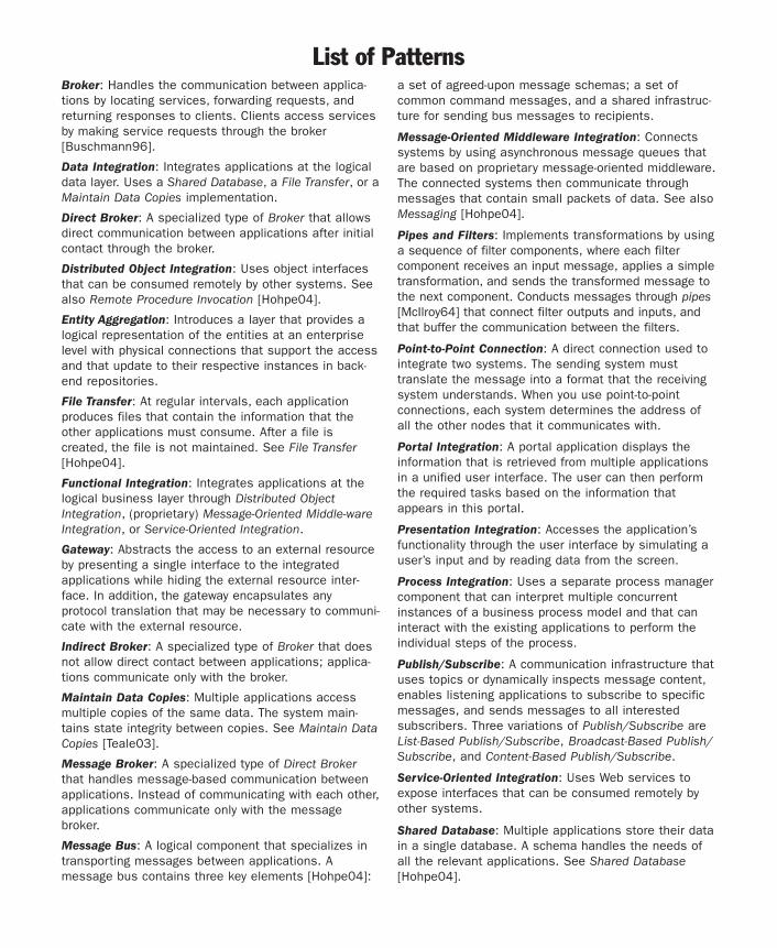
Broker: Handles the communication between applica-tions by locating services, forwarding requests, andreturning responses to clients. Clients access servicesby making service requests through the broker[Buschmann96].
Data Integration: Integrates applications at the logicaldata layer. Uses a Shared Database, a File Transfer, or aMaintain Data Copies implementation.
Direct Broker: A specialized type of Broker that allowsdirect communication between applications after initialcontact through the broker.
Distributed Object Integration: Uses object interfacesthat can be consumed remotely by other systems. Seealso Remote Procedure Invocation [Hohpe04].
Entity Aggregation: Introduces a layer that provides alogical representation of the entities at an enterpriselevel with physical connections that support the accessand that update to their respective instances in back-end repositories.
File Transfer: At regular intervals, each applicationproduces files that contain the information that theother applications must consume. After a file iscreated, the file is not maintained. See File Transfer[Hohpe04].
Functional Integration: Integrates applications at thelogical business layer through Distributed ObjectIntegration, (proprietary) Message-Oriented Middle-wareIntegration, or Service-Oriented Integration.
Gateway: Abstracts the access to an external resourceby presenting a single interface to the integratedapplications while hiding the external resource inter-face. In addition, the gateway encapsulates anyprotocol translation that may be necessary to communi-cate with the external resource.
Indirect Broker: A specialized type of Broker that doesnot allow direct contact between applications; applica-tions communicate only with the broker.
Maintain Data Copies: Multiple applications accessmultiple copies of the same data. The system main-tains state integrity between copies. See Maintain DataCopies [Teale03].
Message Broker: A specialized type of Direct Brokerthat handles message-based communication betweenapplications. Instead of communicating with each other,applications communicate only with the messagebroker.
Message Bus: A logical component that specializes intransporting messages between applications. Amessage bus contains three key elements [Hohpe04]:
a set of agreed-upon message schemas; a set ofcommon command messages, and a shared infrastruc-ture for sending bus messages to recipients.
Message-Oriented Middleware Integration: Connectssystems by using asynchronous message queues thatare based on proprietary message-oriented middleware.The connected systems then communicate throughmessages that contain small packets of data. See alsoMessaging [Hohpe04].
Pipes and Filters: Implements transformations by usinga sequence of filter components, where each filtercomponent receives an input message, applies a simpletransformation, and sends the transformed message tothe next component. Conducts messages through pipes[McIlroy64] that connect filter outputs and inputs, andthat buffer the communication between the filters.
Point-to-Point Connection: A direct connection used tointegrate two systems. The sending system musttranslate the message into a format that the receivingsystem understands. When you use point-to-pointconnections, each system determines the address ofall the other nodes that it communicates with.
Portal Integration: A portal application displays theinformation that is retrieved from multiple applicationsin a unified user interface. The user can then performthe required tasks based on the information thatappears in this portal.
Presentation Integration: Accesses the application’sfunctionality through the user interface by simulating auser’s input and by reading data from the screen.
Process Integration: Uses a separate process managercomponent that can interpret multiple concurrentinstances of a business process model and that caninteract with the existing applications to perform theindividual steps of the process.
Publish/Subscribe: A communication infrastructure thatuses topics or dynamically inspects message content,enables listening applications to subscribe to specificmessages, and sends messages to all interestedsubscribers. Three variations of Publish/Subscribe areList-Based Publish/Subscribe, Broadcast-Based Publish/Subscribe, and Content-Based Publish/Subscribe.
Service-Oriented Integration: Uses Web services toexpose interfaces that can be consumed remotely byother systems.
Shared Database: Multiple applications store their datain a single database. A schema handles the needs ofall the relevant applications. See Shared Database[Hohpe04].
List of Patterns

ContentsPreface xi
Who Should Read This Book . . . . . . . . . . . . . . . . . . . . . . . . . . . . . . . . . . . . . . . . . . . . xiHow This Book Is Organized. . . . . . . . . . . . . . . . . . . . . . . . . . . . . . . . . . . . . . . . . . . . xiiDocumentation Conventions . . . . . . . . . . . . . . . . . . . . . . . . . . . . . . . . . . . . . . . . . . . xivCommunity . . . . . . . . . . . . . . . . . . . . . . . . . . . . . . . . . . . . . . . . . . . . . . . . . . . . . . . . xivFeedback and Support . . . . . . . . . . . . . . . . . . . . . . . . . . . . . . . . . . . . . . . . . . . . . . . . xvContributors . . . . . . . . . . . . . . . . . . . . . . . . . . . . . . . . . . . . . . . . . . . . . . . . . . . . . . . . xvAbout the Principal Authors . . . . . . . . . . . . . . . . . . . . . . . . . . . . . . . . . . . . . . . . . . . . xvi
Chapter 1Integration and Patterns 1
The Problem of Integration . . . . . . . . . . . . . . . . . . . . . . . . . . . . . . . . . . . . . . . . . . . . . . 2Integration Architecture . . . . . . . . . . . . . . . . . . . . . . . . . . . . . . . . . . . . . . . . . . . . . . 2Applications . . . . . . . . . . . . . . . . . . . . . . . . . . . . . . . . . . . . . . . . . . . . . . . . . . . . . . 3
The Global Bank Scenario . . . . . . . . . . . . . . . . . . . . . . . . . . . . . . . . . . . . . . . . . . . . . . 4Context . . . . . . . . . . . . . . . . . . . . . . . . . . . . . . . . . . . . . . . . . . . . . . . . . . . . . . . . . . 4Requirements . . . . . . . . . . . . . . . . . . . . . . . . . . . . . . . . . . . . . . . . . . . . . . . . . . . . . 4Next Steps . . . . . . . . . . . . . . . . . . . . . . . . . . . . . . . . . . . . . . . . . . . . . . . . . . . . . . . 6
Patterns . . . . . . . . . . . . . . . . . . . . . . . . . . . . . . . . . . . . . . . . . . . . . . . . . . . . . . . . . . . 7Patterns in Sports . . . . . . . . . . . . . . . . . . . . . . . . . . . . . . . . . . . . . . . . . . . . . . . . . . 7Patterns in Music . . . . . . . . . . . . . . . . . . . . . . . . . . . . . . . . . . . . . . . . . . . . . . . . . . 9Pattern Structure . . . . . . . . . . . . . . . . . . . . . . . . . . . . . . . . . . . . . . . . . . . . . . . . . . 9Pattern-Based Design . . . . . . . . . . . . . . . . . . . . . . . . . . . . . . . . . . . . . . . . . . . . . . 10
Patterns at Global Bank. . . . . . . . . . . . . . . . . . . . . . . . . . . . . . . . . . . . . . . . . . . . . . . 11Next Chapter . . . . . . . . . . . . . . . . . . . . . . . . . . . . . . . . . . . . . . . . . . . . . . . . . . . . . . . 17
Chapter 2Using Patterns to Design the Baseline Architecture 19
Meeting the Requirements of Global Bank . . . . . . . . . . . . . . . . . . . . . . . . . . . . . . . . . 19Using Patterns to Communicate Design Decisions . . . . . . . . . . . . . . . . . . . . . . . . . 20The Role of a Baseline Architecture . . . . . . . . . . . . . . . . . . . . . . . . . . . . . . . . . . . . 21
Designing the Global Bank Baseline Architecture . . . . . . . . . . . . . . . . . . . . . . . . . . . . 21View Scheduled Payments Use Case . . . . . . . . . . . . . . . . . . . . . . . . . . . . . . . . . . . 22Adding a Message Broker for the Loan Systems . . . . . . . . . . . . . . . . . . . . . . . . . . . 29Execute Scheduled Payment Use Case. . . . . . . . . . . . . . . . . . . . . . . . . . . . . . . . . . 33Designing for Execute Scheduled Payment and Receive Payment Response . . . . . . . 35Accessing Account Services on the Mainframe . . . . . . . . . . . . . . . . . . . . . . . . . . . . 44The Portal Web Application . . . . . . . . . . . . . . . . . . . . . . . . . . . . . . . . . . . . . . . . . . 46Global Bank Portal Application . . . . . . . . . . . . . . . . . . . . . . . . . . . . . . . . . . . . . . . . 49Implementing the Global Bank Scenario . . . . . . . . . . . . . . . . . . . . . . . . . . . . . . . . . 50
Next Chapter . . . . . . . . . . . . . . . . . . . . . . . . . . . . . . . . . . . . . . . . . . . . . . . . . . . . . . . 53
Contents v
Chapter 3Integrating Layer 55
Level of Automation . . . . . . . . . . . . . . . . . . . . . . . . . . . . . . . . . . . . . . . . . . . . . . . . . 55Level of Abstraction . . . . . . . . . . . . . . . . . . . . . . . . . . . . . . . . . . . . . . . . . . . . . . . . . . 56Maintaining State . . . . . . . . . . . . . . . . . . . . . . . . . . . . . . . . . . . . . . . . . . . . . . . . . . . 56Coupling . . . . . . . . . . . . . . . . . . . . . . . . . . . . . . . . . . . . . . . . . . . . . . . . . . . . . . . . . . 57Semantic Dissonance . . . . . . . . . . . . . . . . . . . . . . . . . . . . . . . . . . . . . . . . . . . . . . . . 57Choosing an Integration Layer Type . . . . . . . . . . . . . . . . . . . . . . . . . . . . . . . . . . . . . . 57
Portal Integration . . . . . . . . . . . . . . . . . . . . . . . . . . . . . . . . . . . . . . . . . . . . . . . . . 58Entity Aggregation . . . . . . . . . . . . . . . . . . . . . . . . . . . . . . . . . . . . . . . . . . . . . . . . . 59Process Integration . . . . . . . . . . . . . . . . . . . . . . . . . . . . . . . . . . . . . . . . . . . . . . . . 59
Integrating Layer Patterns . . . . . . . . . . . . . . . . . . . . . . . . . . . . . . . . . . . . . . . . . . . . . 60Entity Aggregation . . . . . . . . . . . . . . . . . . . . . . . . . . . . . . . . . . . . . . . . . . . . . . . . . . . 61
Context . . . . . . . . . . . . . . . . . . . . . . . . . . . . . . . . . . . . . . . . . . . . . . . . . . . . . . . . . 61Problem . . . . . . . . . . . . . . . . . . . . . . . . . . . . . . . . . . . . . . . . . . . . . . . . . . . . . . . . 61Forces . . . . . . . . . . . . . . . . . . . . . . . . . . . . . . . . . . . . . . . . . . . . . . . . . . . . . . . . . 61Solution . . . . . . . . . . . . . . . . . . . . . . . . . . . . . . . . . . . . . . . . . . . . . . . . . . . . . . . . 62Example . . . . . . . . . . . . . . . . . . . . . . . . . . . . . . . . . . . . . . . . . . . . . . . . . . . . . . . . 72Resulting Context . . . . . . . . . . . . . . . . . . . . . . . . . . . . . . . . . . . . . . . . . . . . . . . . . 73Testing Considerations . . . . . . . . . . . . . . . . . . . . . . . . . . . . . . . . . . . . . . . . . . . . . 74Security Considerations . . . . . . . . . . . . . . . . . . . . . . . . . . . . . . . . . . . . . . . . . . . . . 74Operational Considerations . . . . . . . . . . . . . . . . . . . . . . . . . . . . . . . . . . . . . . . . . . 74Known Uses . . . . . . . . . . . . . . . . . . . . . . . . . . . . . . . . . . . . . . . . . . . . . . . . . . . . . 75Related Patterns . . . . . . . . . . . . . . . . . . . . . . . . . . . . . . . . . . . . . . . . . . . . . . . . . . 75
Process Integration . . . . . . . . . . . . . . . . . . . . . . . . . . . . . . . . . . . . . . . . . . . . . . . . . . 76Context . . . . . . . . . . . . . . . . . . . . . . . . . . . . . . . . . . . . . . . . . . . . . . . . . . . . . . . . . 76Problem . . . . . . . . . . . . . . . . . . . . . . . . . . . . . . . . . . . . . . . . . . . . . . . . . . . . . . . . 76Forces . . . . . . . . . . . . . . . . . . . . . . . . . . . . . . . . . . . . . . . . . . . . . . . . . . . . . . . . . 76Solution . . . . . . . . . . . . . . . . . . . . . . . . . . . . . . . . . . . . . . . . . . . . . . . . . . . . . . . . 77Implementation Details . . . . . . . . . . . . . . . . . . . . . . . . . . . . . . . . . . . . . . . . . . . . . 80Example . . . . . . . . . . . . . . . . . . . . . . . . . . . . . . . . . . . . . . . . . . . . . . . . . . . . . . . . 82Resulting Context . . . . . . . . . . . . . . . . . . . . . . . . . . . . . . . . . . . . . . . . . . . . . . . . . 82Testing Considerations . . . . . . . . . . . . . . . . . . . . . . . . . . . . . . . . . . . . . . . . . . . . . 84Related Patterns . . . . . . . . . . . . . . . . . . . . . . . . . . . . . . . . . . . . . . . . . . . . . . . . . . 85Acknowledgments . . . . . . . . . . . . . . . . . . . . . . . . . . . . . . . . . . . . . . . . . . . . . . . . . 85
Implementing Process Integration with BizTalk Server 2004 . . . . . . . . . . . . . . . . . . . . 86Context . . . . . . . . . . . . . . . . . . . . . . . . . . . . . . . . . . . . . . . . . . . . . . . . . . . . . . . . . 86Background . . . . . . . . . . . . . . . . . . . . . . . . . . . . . . . . . . . . . . . . . . . . . . . . . . . . . 86Implementation Strategy . . . . . . . . . . . . . . . . . . . . . . . . . . . . . . . . . . . . . . . . . . . . 86Example . . . . . . . . . . . . . . . . . . . . . . . . . . . . . . . . . . . . . . . . . . . . . . . . . . . . . . . . 91Resulting Context . . . . . . . . . . . . . . . . . . . . . . . . . . . . . . . . . . . . . . . . . . . . . . . . 103Testing Considerations . . . . . . . . . . . . . . . . . . . . . . . . . . . . . . . . . . . . . . . . . . . . 104Security Considerations . . . . . . . . . . . . . . . . . . . . . . . . . . . . . . . . . . . . . . . . . . . . 104Operational Considerations . . . . . . . . . . . . . . . . . . . . . . . . . . . . . . . . . . . . . . . . . 105Related Patterns . . . . . . . . . . . . . . . . . . . . . . . . . . . . . . . . . . . . . . . . . . . . . . . . . 105Acknowledgments . . . . . . . . . . . . . . . . . . . . . . . . . . . . . . . . . . . . . . . . . . . . . . . . 105

Contentsvi
Portal Integration . . . . . . . . . . . . . . . . . . . . . . . . . . . . . . . . . . . . . . . . . . . . . . . . . . 106Context . . . . . . . . . . . . . . . . . . . . . . . . . . . . . . . . . . . . . . . . . . . . . . . . . . . . . . . . 106Problem . . . . . . . . . . . . . . . . . . . . . . . . . . . . . . . . . . . . . . . . . . . . . . . . . . . . . . . 106Forces . . . . . . . . . . . . . . . . . . . . . . . . . . . . . . . . . . . . . . . . . . . . . . . . . . . . . . . . 106Solution . . . . . . . . . . . . . . . . . . . . . . . . . . . . . . . . . . . . . . . . . . . . . . . . . . . . . . . 107Example . . . . . . . . . . . . . . . . . . . . . . . . . . . . . . . . . . . . . . . . . . . . . . . . . . . . . . . 109Resulting Context . . . . . . . . . . . . . . . . . . . . . . . . . . . . . . . . . . . . . . . . . . . . . . . . 109
Chapter 4System Connections 111
Connecting to Layered Applications . . . . . . . . . . . . . . . . . . . . . . . . . . . . . . . . . . . . . 111Data Integration . . . . . . . . . . . . . . . . . . . . . . . . . . . . . . . . . . . . . . . . . . . . . . . . . . . 114Presentation Integration . . . . . . . . . . . . . . . . . . . . . . . . . . . . . . . . . . . . . . . . . . . . . 117Functional Integration . . . . . . . . . . . . . . . . . . . . . . . . . . . . . . . . . . . . . . . . . . . . . . . 118
Credit Scoring Example . . . . . . . . . . . . . . . . . . . . . . . . . . . . . . . . . . . . . . . . . . . . 119Kinds of Functional Integration . . . . . . . . . . . . . . . . . . . . . . . . . . . . . . . . . . . . . . 119
System Connection Patterns . . . . . . . . . . . . . . . . . . . . . . . . . . . . . . . . . . . . . . . . . . 120Data Integration . . . . . . . . . . . . . . . . . . . . . . . . . . . . . . . . . . . . . . . . . . . . . . . . . . . 124
Context . . . . . . . . . . . . . . . . . . . . . . . . . . . . . . . . . . . . . . . . . . . . . . . . . . . . . . . . 124Problem . . . . . . . . . . . . . . . . . . . . . . . . . . . . . . . . . . . . . . . . . . . . . . . . . . . . . . . 124Forces . . . . . . . . . . . . . . . . . . . . . . . . . . . . . . . . . . . . . . . . . . . . . . . . . . . . . . . . 124Solution . . . . . . . . . . . . . . . . . . . . . . . . . . . . . . . . . . . . . . . . . . . . . . . . . . . . . . . 125Example . . . . . . . . . . . . . . . . . . . . . . . . . . . . . . . . . . . . . . . . . . . . . . . . . . . . . . . 127Resulting Context . . . . . . . . . . . . . . . . . . . . . . . . . . . . . . . . . . . . . . . . . . . . . . . . 127Acknowledgments . . . . . . . . . . . . . . . . . . . . . . . . . . . . . . . . . . . . . . . . . . . . . . . . 134
Functional Integration . . . . . . . . . . . . . . . . . . . . . . . . . . . . . . . . . . . . . . . . . . . . . . . 135Context . . . . . . . . . . . . . . . . . . . . . . . . . . . . . . . . . . . . . . . . . . . . . . . . . . . . . . . . 135Problem . . . . . . . . . . . . . . . . . . . . . . . . . . . . . . . . . . . . . . . . . . . . . . . . . . . . . . . 135Forces . . . . . . . . . . . . . . . . . . . . . . . . . . . . . . . . . . . . . . . . . . . . . . . . . . . . . . . . 135Solution . . . . . . . . . . . . . . . . . . . . . . . . . . . . . . . . . . . . . . . . . . . . . . . . . . . . . . . 136Resulting Context . . . . . . . . . . . . . . . . . . . . . . . . . . . . . . . . . . . . . . . . . . . . . . . . 138Testing Considerations . . . . . . . . . . . . . . . . . . . . . . . . . . . . . . . . . . . . . . . . . . . . 144Security Considerations . . . . . . . . . . . . . . . . . . . . . . . . . . . . . . . . . . . . . . . . . . . . 144Acknowledgments . . . . . . . . . . . . . . . . . . . . . . . . . . . . . . . . . . . . . . . . . . . . . . . . 145
Service-Oriented Integration . . . . . . . . . . . . . . . . . . . . . . . . . . . . . . . . . . . . . . . . . . . 146Context . . . . . . . . . . . . . . . . . . . . . . . . . . . . . . . . . . . . . . . . . . . . . . . . . . . . . . . . 146Problem . . . . . . . . . . . . . . . . . . . . . . . . . . . . . . . . . . . . . . . . . . . . . . . . . . . . . . . 146Forces . . . . . . . . . . . . . . . . . . . . . . . . . . . . . . . . . . . . . . . . . . . . . . . . . . . . . . . . 146Solution . . . . . . . . . . . . . . . . . . . . . . . . . . . . . . . . . . . . . . . . . . . . . . . . . . . . . . . 148Example . . . . . . . . . . . . . . . . . . . . . . . . . . . . . . . . . . . . . . . . . . . . . . . . . . . . . . . 153Resulting Context . . . . . . . . . . . . . . . . . . . . . . . . . . . . . . . . . . . . . . . . . . . . . . . . 153Security Considerations . . . . . . . . . . . . . . . . . . . . . . . . . . . . . . . . . . . . . . . . . . . . 155Related Patterns . . . . . . . . . . . . . . . . . . . . . . . . . . . . . . . . . . . . . . . . . . . . . . . . . 155Acknowledgments . . . . . . . . . . . . . . . . . . . . . . . . . . . . . . . . . . . . . . . . . . . . . . . . 155

Contents vii
Implementing Service-Oriented Integration with ASP.NET . . . . . . . . . . . . . . . . . . . . . . 157Context . . . . . . . . . . . . . . . . . . . . . . . . . . . . . . . . . . . . . . . . . . . . . . . . . . . . . . . . 157Background . . . . . . . . . . . . . . . . . . . . . . . . . . . . . . . . . . . . . . . . . . . . . . . . . . . . 157Implementation Strategy . . . . . . . . . . . . . . . . . . . . . . . . . . . . . . . . . . . . . . . . . . . 158Example: Building an ASP.NET Web Service to Access the Mainframe Gateway . . . . 164Resulting Context . . . . . . . . . . . . . . . . . . . . . . . . . . . . . . . . . . . . . . . . . . . . . . . . 179Testing Considerations . . . . . . . . . . . . . . . . . . . . . . . . . . . . . . . . . . . . . . . . . . . . 179Security Considerations . . . . . . . . . . . . . . . . . . . . . . . . . . . . . . . . . . . . . . . . . . . . 181Acknowledgments . . . . . . . . . . . . . . . . . . . . . . . . . . . . . . . . . . . . . . . . . . . . . . . . 181
Implementing Service-Oriented Integration with BizTalkServer 2004 . . . . . . . . . . . . . . . . . . . . . . . . . . . . . . . . . . . . . . . . . . . . . . . . . . . . 182Context . . . . . . . . . . . . . . . . . . . . . . . . . . . . . . . . . . . . . . . . . . . . . . . . . . . . . . . . 182Background . . . . . . . . . . . . . . . . . . . . . . . . . . . . . . . . . . . . . . . . . . . . . . . . . . . . 182Implementation Strategy . . . . . . . . . . . . . . . . . . . . . . . . . . . . . . . . . . . . . . . . . . . 183Example . . . . . . . . . . . . . . . . . . . . . . . . . . . . . . . . . . . . . . . . . . . . . . . . . . . . . . . 186Resulting Context . . . . . . . . . . . . . . . . . . . . . . . . . . . . . . . . . . . . . . . . . . . . . . . . 203Testing Considerations . . . . . . . . . . . . . . . . . . . . . . . . . . . . . . . . . . . . . . . . . . . . 204Security Considerations . . . . . . . . . . . . . . . . . . . . . . . . . . . . . . . . . . . . . . . . . . . . 204Operational Considerations . . . . . . . . . . . . . . . . . . . . . . . . . . . . . . . . . . . . . . . . . 205Acknowledgments . . . . . . . . . . . . . . . . . . . . . . . . . . . . . . . . . . . . . . . . . . . . . . . . 205
Presentation Integration . . . . . . . . . . . . . . . . . . . . . . . . . . . . . . . . . . . . . . . . . . . . . 206Aliases . . . . . . . . . . . . . . . . . . . . . . . . . . . . . . . . . . . . . . . . . . . . . . . . . . . . . . . . 206Context . . . . . . . . . . . . . . . . . . . . . . . . . . . . . . . . . . . . . . . . . . . . . . . . . . . . . . . . 206Problem . . . . . . . . . . . . . . . . . . . . . . . . . . . . . . . . . . . . . . . . . . . . . . . . . . . . . . . 206Forces . . . . . . . . . . . . . . . . . . . . . . . . . . . . . . . . . . . . . . . . . . . . . . . . . . . . . . . . 206Solution . . . . . . . . . . . . . . . . . . . . . . . . . . . . . . . . . . . . . . . . . . . . . . . . . . . . . . . 207Example . . . . . . . . . . . . . . . . . . . . . . . . . . . . . . . . . . . . . . . . . . . . . . . . . . . . . . . 209Resulting Context . . . . . . . . . . . . . . . . . . . . . . . . . . . . . . . . . . . . . . . . . . . . . . . . 210Testing Considerations . . . . . . . . . . . . . . . . . . . . . . . . . . . . . . . . . . . . . . . . . . . . 211Security Considerations . . . . . . . . . . . . . . . . . . . . . . . . . . . . . . . . . . . . . . . . . . . . 212Acknowledgments . . . . . . . . . . . . . . . . . . . . . . . . . . . . . . . . . . . . . . . . . . . . . . . . 212
Chapter 5Integration Topologies 213
Point-to-Point Connection . . . . . . . . . . . . . . . . . . . . . . . . . . . . . . . . . . . . . . . . . . . . . 214Broker . . . . . . . . . . . . . . . . . . . . . . . . . . . . . . . . . . . . . . . . . . . . . . . . . . . . . . . . . . 215
Broker Examples . . . . . . . . . . . . . . . . . . . . . . . . . . . . . . . . . . . . . . . . . . . . . . . . . 218Message Bus . . . . . . . . . . . . . . . . . . . . . . . . . . . . . . . . . . . . . . . . . . . . . . . . . . . . . 221Publish/Subscribe. . . . . . . . . . . . . . . . . . . . . . . . . . . . . . . . . . . . . . . . . . . . . . . . . . 223
List-Based Publish/Subscribe . . . . . . . . . . . . . . . . . . . . . . . . . . . . . . . . . . . . . . . 223Broadcast-Based Publish/Subscribe . . . . . . . . . . . . . . . . . . . . . . . . . . . . . . . . . . 224Content-Based Publish/Subscribe . . . . . . . . . . . . . . . . . . . . . . . . . . . . . . . . . . . . 224
A More Detailed Look at Topologies . . . . . . . . . . . . . . . . . . . . . . . . . . . . . . . . . . . . . 225Topology Levels . . . . . . . . . . . . . . . . . . . . . . . . . . . . . . . . . . . . . . . . . . . . . . . . . . 225
Contentsviii
Using Topologies Together . . . . . . . . . . . . . . . . . . . . . . . . . . . . . . . . . . . . . . . . . . . . 229Point-to-Point Connection . . . . . . . . . . . . . . . . . . . . . . . . . . . . . . . . . . . . . . . . . . . 230Broker . . . . . . . . . . . . . . . . . . . . . . . . . . . . . . . . . . . . . . . . . . . . . . . . . . . . . . . . 231Message Bus and Publish/Subscribe . . . . . . . . . . . . . . . . . . . . . . . . . . . . . . . . . . 231
Integration Topology Level Patterns . . . . . . . . . . . . . . . . . . . . . . . . . . . . . . . . . . . . . 236Message Broker . . . . . . . . . . . . . . . . . . . . . . . . . . . . . . . . . . . . . . . . . . . . . . . . . . . 237
Aliases . . . . . . . . . . . . . . . . . . . . . . . . . . . . . . . . . . . . . . . . . . . . . . . . . . . . . . . . 237Context . . . . . . . . . . . . . . . . . . . . . . . . . . . . . . . . . . . . . . . . . . . . . . . . . . . . . . . . 237Problem . . . . . . . . . . . . . . . . . . . . . . . . . . . . . . . . . . . . . . . . . . . . . . . . . . . . . . . 237Forces . . . . . . . . . . . . . . . . . . . . . . . . . . . . . . . . . . . . . . . . . . . . . . . . . . . . . . . . 237Solution . . . . . . . . . . . . . . . . . . . . . . . . . . . . . . . . . . . . . . . . . . . . . . . . . . . . . . . 238Example . . . . . . . . . . . . . . . . . . . . . . . . . . . . . . . . . . . . . . . . . . . . . . . . . . . . . . . 239Resulting Context . . . . . . . . . . . . . . . . . . . . . . . . . . . . . . . . . . . . . . . . . . . . . . . . 240Testing Considerations . . . . . . . . . . . . . . . . . . . . . . . . . . . . . . . . . . . . . . . . . . . . 242Security Considerations . . . . . . . . . . . . . . . . . . . . . . . . . . . . . . . . . . . . . . . . . . . . 242Operational Considerations . . . . . . . . . . . . . . . . . . . . . . . . . . . . . . . . . . . . . . . . . 243Known Uses . . . . . . . . . . . . . . . . . . . . . . . . . . . . . . . . . . . . . . . . . . . . . . . . . . . . 243Variants . . . . . . . . . . . . . . . . . . . . . . . . . . . . . . . . . . . . . . . . . . . . . . . . . . . . . . . 243Related Patterns . . . . . . . . . . . . . . . . . . . . . . . . . . . . . . . . . . . . . . . . . . . . . . . . . 243Acknowledgments . . . . . . . . . . . . . . . . . . . . . . . . . . . . . . . . . . . . . . . . . . . . . . . . 244
Implementing Message Broker with BizTalk Server 2004. . . . . . . . . . . . . . . . . . . . . . 245Context . . . . . . . . . . . . . . . . . . . . . . . . . . . . . . . . . . . . . . . . . . . . . . . . . . . . . . . . 245Background . . . . . . . . . . . . . . . . . . . . . . . . . . . . . . . . . . . . . . . . . . . . . . . . . . . . 245Implementation Strategy . . . . . . . . . . . . . . . . . . . . . . . . . . . . . . . . . . . . . . . . . . . 246Example . . . . . . . . . . . . . . . . . . . . . . . . . . . . . . . . . . . . . . . . . . . . . . . . . . . . . . . 249Resulting Context . . . . . . . . . . . . . . . . . . . . . . . . . . . . . . . . . . . . . . . . . . . . . . . . 255Testing Considerations . . . . . . . . . . . . . . . . . . . . . . . . . . . . . . . . . . . . . . . . . . . . 256Security Considerations . . . . . . . . . . . . . . . . . . . . . . . . . . . . . . . . . . . . . . . . . . . . 256Operational Considerations . . . . . . . . . . . . . . . . . . . . . . . . . . . . . . . . . . . . . . . . . 257Variants . . . . . . . . . . . . . . . . . . . . . . . . . . . . . . . . . . . . . . . . . . . . . . . . . . . . . . . 257Business Rule Engine . . . . . . . . . . . . . . . . . . . . . . . . . . . . . . . . . . . . . . . . . . . . . 257Related Patterns . . . . . . . . . . . . . . . . . . . . . . . . . . . . . . . . . . . . . . . . . . . . . . . . . 258Acknowledgments . . . . . . . . . . . . . . . . . . . . . . . . . . . . . . . . . . . . . . . . . . . . . . . . 259
Message Bus . . . . . . . . . . . . . . . . . . . . . . . . . . . . . . . . . . . . . . . . . . . . . . . . . . . . . 260Context . . . . . . . . . . . . . . . . . . . . . . . . . . . . . . . . . . . . . . . . . . . . . . . . . . . . . . . . 260Problem . . . . . . . . . . . . . . . . . . . . . . . . . . . . . . . . . . . . . . . . . . . . . . . . . . . . . . . 260Forces . . . . . . . . . . . . . . . . . . . . . . . . . . . . . . . . . . . . . . . . . . . . . . . . . . . . . . . . 260Solution . . . . . . . . . . . . . . . . . . . . . . . . . . . . . . . . . . . . . . . . . . . . . . . . . . . . . . . 261Example . . . . . . . . . . . . . . . . . . . . . . . . . . . . . . . . . . . . . . . . . . . . . . . . . . . . . . . 266Resulting Context . . . . . . . . . . . . . . . . . . . . . . . . . . . . . . . . . . . . . . . . . . . . . . . . 269Security Considerations . . . . . . . . . . . . . . . . . . . . . . . . . . . . . . . . . . . . . . . . . . . . 270Operational Considerations . . . . . . . . . . . . . . . . . . . . . . . . . . . . . . . . . . . . . . . . . 270Related Patterns . . . . . . . . . . . . . . . . . . . . . . . . . . . . . . . . . . . . . . . . . . . . . . . . . 271Acknowledgments . . . . . . . . . . . . . . . . . . . . . . . . . . . . . . . . . . . . . . . . . . . . . . . . 271

Contents ix
Publish/Subscribe. . . . . . . . . . . . . . . . . . . . . . . . . . . . . . . . . . . . . . . . . . . . . . . . . . 272Aliases . . . . . . . . . . . . . . . . . . . . . . . . . . . . . . . . . . . . . . . . . . . . . . . . . . . . . . . . 272Context . . . . . . . . . . . . . . . . . . . . . . . . . . . . . . . . . . . . . . . . . . . . . . . . . . . . . . . . 272Problem . . . . . . . . . . . . . . . . . . . . . . . . . . . . . . . . . . . . . . . . . . . . . . . . . . . . . . . 272Forces . . . . . . . . . . . . . . . . . . . . . . . . . . . . . . . . . . . . . . . . . . . . . . . . . . . . . . . . 272Solution . . . . . . . . . . . . . . . . . . . . . . . . . . . . . . . . . . . . . . . . . . . . . . . . . . . . . . . 273Example . . . . . . . . . . . . . . . . . . . . . . . . . . . . . . . . . . . . . . . . . . . . . . . . . . . . . . . 280Resulting Context . . . . . . . . . . . . . . . . . . . . . . . . . . . . . . . . . . . . . . . . . . . . . . . . 280Testing Considerations . . . . . . . . . . . . . . . . . . . . . . . . . . . . . . . . . . . . . . . . . . . . 281Security Considerations . . . . . . . . . . . . . . . . . . . . . . . . . . . . . . . . . . . . . . . . . . . . 281Operational Considerations . . . . . . . . . . . . . . . . . . . . . . . . . . . . . . . . . . . . . . . . . 281Related Patterns . . . . . . . . . . . . . . . . . . . . . . . . . . . . . . . . . . . . . . . . . . . . . . . . . 282Acknowledgments . . . . . . . . . . . . . . . . . . . . . . . . . . . . . . . . . . . . . . . . . . . . . . . . 282
Chapter 6Additional Integration Patterns 283
Pipes and Filters . . . . . . . . . . . . . . . . . . . . . . . . . . . . . . . . . . . . . . . . . . . . . . . . . . . 283Gateway . . . . . . . . . . . . . . . . . . . . . . . . . . . . . . . . . . . . . . . . . . . . . . . . . . . . . . . . . 284Integration Layers Patterns . . . . . . . . . . . . . . . . . . . . . . . . . . . . . . . . . . . . . . . . . . . 285Pipes and Filters . . . . . . . . . . . . . . . . . . . . . . . . . . . . . . . . . . . . . . . . . . . . . . . . . . . 286
Aliases . . . . . . . . . . . . . . . . . . . . . . . . . . . . . . . . . . . . . . . . . . . . . . . . . . . . . . . . 286Context . . . . . . . . . . . . . . . . . . . . . . . . . . . . . . . . . . . . . . . . . . . . . . . . . . . . . . . . 286Problem . . . . . . . . . . . . . . . . . . . . . . . . . . . . . . . . . . . . . . . . . . . . . . . . . . . . . . . 286Forces . . . . . . . . . . . . . . . . . . . . . . . . . . . . . . . . . . . . . . . . . . . . . . . . . . . . . . . . 286Solution . . . . . . . . . . . . . . . . . . . . . . . . . . . . . . . . . . . . . . . . . . . . . . . . . . . . . . . 287Example . . . . . . . . . . . . . . . . . . . . . . . . . . . . . . . . . . . . . . . . . . . . . . . . . . . . . . . 290Resulting Context . . . . . . . . . . . . . . . . . . . . . . . . . . . . . . . . . . . . . . . . . . . . . . . . 292Testing Considerations . . . . . . . . . . . . . . . . . . . . . . . . . . . . . . . . . . . . . . . . . . . . 293Known Uses . . . . . . . . . . . . . . . . . . . . . . . . . . . . . . . . . . . . . . . . . . . . . . . . . . . . 293Related Patterns . . . . . . . . . . . . . . . . . . . . . . . . . . . . . . . . . . . . . . . . . . . . . . . . . 295Acknowledgments . . . . . . . . . . . . . . . . . . . . . . . . . . . . . . . . . . . . . . . . . . . . . . . . 295
Implementing Pipes and Filters with BizTalk Server 2004 . . . . . . . . . . . . . . . . . . . . . 296Context . . . . . . . . . . . . . . . . . . . . . . . . . . . . . . . . . . . . . . . . . . . . . . . . . . . . . . . . 296Background . . . . . . . . . . . . . . . . . . . . . . . . . . . . . . . . . . . . . . . . . . . . . . . . . . . . 296Implementation Strategy . . . . . . . . . . . . . . . . . . . . . . . . . . . . . . . . . . . . . . . . . . . 297Example . . . . . . . . . . . . . . . . . . . . . . . . . . . . . . . . . . . . . . . . . . . . . . . . . . . . . . . 299Resulting Context . . . . . . . . . . . . . . . . . . . . . . . . . . . . . . . . . . . . . . . . . . . . . . . . 305Testing Considerations . . . . . . . . . . . . . . . . . . . . . . . . . . . . . . . . . . . . . . . . . . . . 305Security Considerations . . . . . . . . . . . . . . . . . . . . . . . . . . . . . . . . . . . . . . . . . . . . 306Operational Considerations . . . . . . . . . . . . . . . . . . . . . . . . . . . . . . . . . . . . . . . . . 306Acknowledgments . . . . . . . . . . . . . . . . . . . . . . . . . . . . . . . . . . . . . . . . . . . . . . . . 307

Contentsx
Gateway . . . . . . . . . . . . . . . . . . . . . . . . . . . . . . . . . . . . . . . . . . . . . . . . . . . . . . . . . 308Context . . . . . . . . . . . . . . . . . . . . . . . . . . . . . . . . . . . . . . . . . . . . . . . . . . . . . . . . 308Problem . . . . . . . . . . . . . . . . . . . . . . . . . . . . . . . . . . . . . . . . . . . . . . . . . . . . . . . 308Forces . . . . . . . . . . . . . . . . . . . . . . . . . . . . . . . . . . . . . . . . . . . . . . . . . . . . . . . . 308Solution . . . . . . . . . . . . . . . . . . . . . . . . . . . . . . . . . . . . . . . . . . . . . . . . . . . . . . . 309Example . . . . . . . . . . . . . . . . . . . . . . . . . . . . . . . . . . . . . . . . . . . . . . . . . . . . . . . 312Resulting Context . . . . . . . . . . . . . . . . . . . . . . . . . . . . . . . . . . . . . . . . . . . . . . . . 314Testing Considerations . . . . . . . . . . . . . . . . . . . . . . . . . . . . . . . . . . . . . . . . . . . . 315Security Considerations . . . . . . . . . . . . . . . . . . . . . . . . . . . . . . . . . . . . . . . . . . . . 316Operational Considerations . . . . . . . . . . . . . . . . . . . . . . . . . . . . . . . . . . . . . . . . . 317Related Patterns . . . . . . . . . . . . . . . . . . . . . . . . . . . . . . . . . . . . . . . . . . . . . . . . . 317Acknowledgments . . . . . . . . . . . . . . . . . . . . . . . . . . . . . . . . . . . . . . . . . . . . . . . . 318
Implementing Gateway with Host Integration Server 2004. . . . . . . . . . . . . . . . . . . . . 319Context . . . . . . . . . . . . . . . . . . . . . . . . . . . . . . . . . . . . . . . . . . . . . . . . . . . . . . . . 319Background . . . . . . . . . . . . . . . . . . . . . . . . . . . . . . . . . . . . . . . . . . . . . . . . . . . . 319Implementation Strategy . . . . . . . . . . . . . . . . . . . . . . . . . . . . . . . . . . . . . . . . . . . 320Example . . . . . . . . . . . . . . . . . . . . . . . . . . . . . . . . . . . . . . . . . . . . . . . . . . . . . . . 331Resulting Context . . . . . . . . . . . . . . . . . . . . . . . . . . . . . . . . . . . . . . . . . . . . . . . . 339Tests . . . . . . . . . . . . . . . . . . . . . . . . . . . . . . . . . . . . . . . . . . . . . . . . . . . . . . . . . 339
Chapter 7Project Notebook 341
Interpreting the Artifacts . . . . . . . . . . . . . . . . . . . . . . . . . . . . . . . . . . . . . . . . . . . . . 342Global Bank Business Context . . . . . . . . . . . . . . . . . . . . . . . . . . . . . . . . . . . . . . . . . 342
Convergence in the Banking Industry . . . . . . . . . . . . . . . . . . . . . . . . . . . . . . . . . . 342Stakeholder Viewpoints . . . . . . . . . . . . . . . . . . . . . . . . . . . . . . . . . . . . . . . . . . . . . . 344
Board of Directors Viewpoint . . . . . . . . . . . . . . . . . . . . . . . . . . . . . . . . . . . . . . . . 344Chief Executive Officer . . . . . . . . . . . . . . . . . . . . . . . . . . . . . . . . . . . . . . . . . . . . 346General Manager of Banking . . . . . . . . . . . . . . . . . . . . . . . . . . . . . . . . . . . . . . . . 351Director of Electronic Bill Presentment and Payment . . . . . . . . . . . . . . . . . . . . . . . 354Electronic Bill Presentment and Payment Supervisor . . . . . . . . . . . . . . . . . . . . . . . 355
From Business Scenario to Technical Solution . . . . . . . . . . . . . . . . . . . . . . . . . . . . . 355Viewpoints Within the Enterprise Architecture . . . . . . . . . . . . . . . . . . . . . . . . . . . . 357Business Architecture Views . . . . . . . . . . . . . . . . . . . . . . . . . . . . . . . . . . . . . . . . 358Integration Architecture Views . . . . . . . . . . . . . . . . . . . . . . . . . . . . . . . . . . . . . . . 365Integration Patterns . . . . . . . . . . . . . . . . . . . . . . . . . . . . . . . . . . . . . . . . . . . . . . 369
Going Forward . . . . . . . . . . . . . . . . . . . . . . . . . . . . . . . . . . . . . . . . . . . . . . . . . . . . . 378
Appendix 379List of Patterns and Pattlets . . . . . . . . . . . . . . . . . . . . . . . . . . . . . . . . . . . . . . . . . . 379
Bibliography 385
Index 389

Preface
Welcome to Integration Patterns, the third patterns release in the pattern & practicesseries from Microsoft. Building on the application patterns presented in EnterpriseSolution Patterns Using Microsoft .NET, this guide applies patterns to solve integra-tion problems within the enterprise.
Integration Patterns explains how the authors of this guide used patterns to designand build an integration architecture in the context of a representative customerscenario. The guide contains a catalog of 18 integration patterns, including imple-mentations that use BizTalk Server 2004, Host Integration Server 2004, ASP.NET,Visual Studio .NET, Visio 2003, and the .NET Framework.
Why does this guide include a scenario? Although reader feedback on previouspatterns releases was positive, they also gave us suggestions for improvement.Readers said that they liked the pattern catalog, but they wanted help understand-ing how to apply patterns to a real scenario. In response to this feedback, the au-thors used a pattern-based approach to build and test a baseline architecture thatmeets the needs of an integration scenario. We incorporated the essence of our actualdesign discussions into the scenario to show how we used patterns to communicateand make design decisions. .Because a well-designed architecture must be traceableto the needs of the business, we included a set of artifacts that trace from high-levelbusiness processes down to code.
The chosen scenario is an online bill payment application in the banking industry.Although we don’t presume to be experts in banking, we did want to use a scenariowith sufficient complexity to illustrate our approach to solving significant technicalchallenges. We expect that you will use your own skills and experience to tailor yoursystems to your enterprise. We hope you find this guide to be a practical and helpfulresource during this effort.
Who Should Read This BookIf you are new to patterns, we suggest that you read Enterprise Solution PatternsUsing Microsoft .NET before you read this guide. This prerequisite reading willintroduce you to patterns that you can apply during the design and implementationof applications.
Integration Patterns is for readers in one or more of the following categories:● Chief technology officers, architects, designers, and developers who understand
application patterns but are new to integration patterns

Prefacexii
● Chief technology officers, architects, designers and developers who are alreadyexperienced in using integration patterns to integrate enterprise solutions
● Chief information officers, chief technology officers, technology directors, and ITmanagers who are responsible for aligning business with technology and inte-grating multiple systems
For those in the first group, the first two chapters are very important to understand-ing the context of integration and the use of patterns during the design process.These chapters will help you understand the next four chapters, which collectivelyform a pattern catalog. You are likely to discover that you have implemented someof these patterns before without knowing that they were patterns.
Readers in the second group can go directly to chapters three through six and usethem as a pattern catalog. After you find a particular pattern you are interested in, itis helpful to review the introductory material at the beginning of the chapter tobetter understand the relationship of this pattern to other adjacent patterns. As youconsider design alternatives for your enterprise, you are likely to find chapter sevenhelpful. This chapter contains examples of business and technology alignmentartifacts and more information on the pattern-based design approach.
Readers in the last group should read chapter one, then go directly to chapter seven.This chapter explains how Global Bank approached the issue of business and tech-nology alignment. This chapter contains example artifacts and more information onthe role of patterns in the design process. If you would like more information abouta specific pattern, use chapters three through six as a pattern catalog and find theappropriate pattern.
How This Book Is OrganizedChapter 1, “Integration and Patterns” introduces the Global Bank scenario that isused throughout this guide and briefly discusses how patterns can help develop-ment teams find workable answers to integration challenges.
Chapter 2, “Using Patterns to Design the Integration Baseline Architecture” uses thelanguage of patterns to explore the decisions and tradeoffs that the members of theGlobal Bank architecture team made while designing and implementing their billpayment system.
Chapters 3 through 5 present a catalog of 18 patterns, which are grouped intoclusters. Each chapter starts by describing how the patterns in a particular clusterare related and then gives direction on when to use the patterns. The implementa-tion patterns include step-by-step instructions and code examples where applicable.Code examples are written in C# and are for example purposes only. The examplecode is not meant to be used in production.
Preface xiii
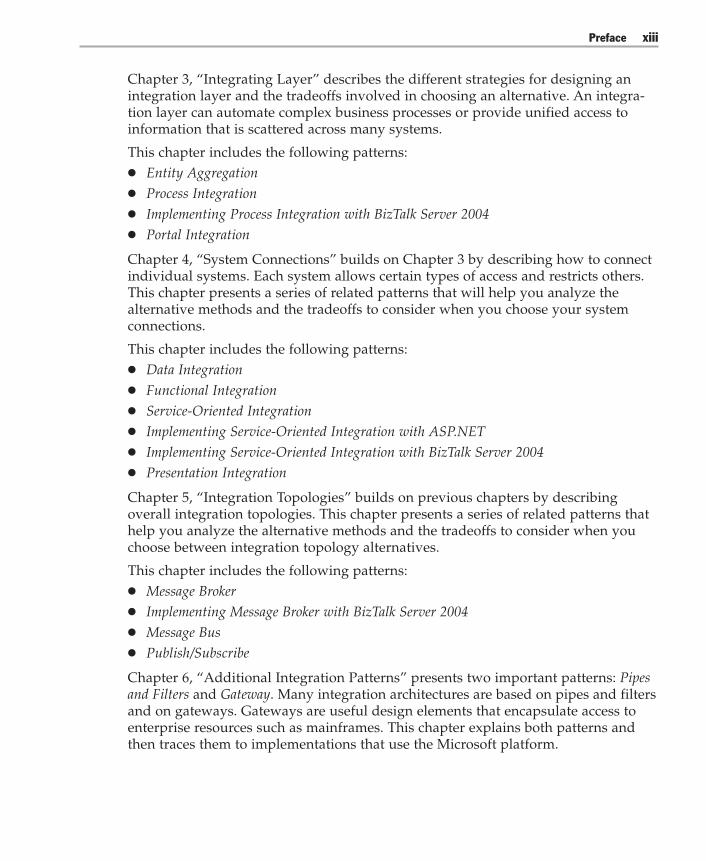
Chapter 3, “Integrating Layer” describes the different strategies for designing anintegration layer and the tradeoffs involved in choosing an alternative. An integra-tion layer can automate complex business processes or provide unified access toinformation that is scattered across many systems.
This chapter includes the following patterns:● Entity Aggregation● Process Integration● Implementing Process Integration with BizTalk Server 2004● Portal Integration
Chapter 4, “System Connections” builds on Chapter 3 by describing how to connectindividual systems. Each system allows certain types of access and restricts others.This chapter presents a series of related patterns that will help you analyze thealternative methods and the tradeoffs to consider when you choose your systemconnections.
This chapter includes the following patterns:● Data Integration● Functional Integration● Service-Oriented Integration● Implementing Service-Oriented Integration with ASP.NET● Implementing Service-Oriented Integration with BizTalk Server 2004● Presentation Integration
Chapter 5, “Integration Topologies” builds on previous chapters by describingoverall integration topologies. This chapter presents a series of related patterns thathelp you analyze the alternative methods and the tradeoffs to consider when youchoose between integration topology alternatives.
This chapter includes the following patterns:● Message Broker● Implementing Message Broker with BizTalk Server 2004● Message Bus● Publish/Subscribe
Chapter 6, “Additional Integration Patterns” presents two important patterns: Pipesand Filters and Gateway. Many integration architectures are based on pipes and filtersand on gateways. Gateways are useful design elements that encapsulate access toenterprise resources such as mainframes. This chapter explains both patterns andthen traces them to implementations that use the Microsoft platform.

Prefacexiv
This chapter includes the following patterns:● Pipes and Filters● Implementing Pipes and Filters with BizTalk Server 2004● Gateway● Implementing Gateway with Host Integration Server 2004
Chapter 7, “Project Notebook” takes a broader view of the Global Bank scenario byshowing the link between business and technology viewpoints. It starts with anoverview of the Global Bank business environment, and then describes the view-points of five key business stakeholders. The chapter then presents a series ofmodels that the Global Bank team produced as they designed the baseline architec-ture based on business requirements. These models trace a path from the ChiefExecutive Officer to the technical solution and show how the team used patternsduring the design process. The chapter also includes additional details about thepattern based approach used in this guide.
Appendix, “List of Patterns and Pattlets,” presents a list of patterns and pattlets thatthis guide mentions, but that it does not discuss in detail. Pattlets are actual patternsthat this book refers to; however, the book does not discuss them in detail.
Documentation ConventionsThis guide uses the following style conventions and terminology.
Table 1: Style Conventions Table
Element Meaning
Bold font Objects, classes, methods, predefined functions, and events.
Italic font Names of patterns and pattlets referenced in this guide. Newterminology also appears in italic on first use.
Monospace font Code examples.
Note Alerts you to supplementary information.
CommunityThe patterns in this guide are part of a new Patterns community on GotDotNet.GotDotNet is a Microsoft .NET Framework Community Web site that usesworkspaces in an online collaborative development environment where .NETFramework developers can create, host, and manage projects throughout the projectlife cycle. You can also use this Patterns community to post questions, providefeedback, or connect with other users for sharing ideas.
Preface xv
Access to the Patterns community is available from the following Web site:
http://gotdotnet.com/team/architecture/patterns
Feedback and SupportQuestions? Comments? Suggestions? For feedback on this guide, please send e-mailto [email protected].
The patterns documented here are designed to jump-start the architecture anddesign of systems integration. Patterns are simple mechanisms that are meant to beapplied to the problem at hand and are usually combined with other patterns. Theyare not meant to be plugged into an application. Example code is provided “as is”and is not intended for production use. It is only intended to illustrate the pattern,and therefore does not include extra code such as exception handling, logging,security, and validation. Although this deliverable has undergone testing and reviewby industry luminaries it is not supported like a traditional Microsoft product.
ContributorsThanks to the following contributing authors: Ward Cunningham, Microsoft Plat-form Architecture Guidance; Ramkumar Kothandaraman, Microsoft Developer andPlatform Evangelism Architecture Strategy Team; Bill Mc Donald, Robert Miles,Ascentium Corporation; Javier Mariscal, Two Connect, Inc.; Raymond Laghaeian,Implement.Com.
Many thanks to the following reviewers who provided invaluable assistance andfeedback: John Sullivan, Thoughtworks; Ralph Johnson, University of Illinois atUrbana-Champaign; Eddie Hulme, EDS; Dave Swift, Chief Architect, Zurich Finan-cial Services; Rupert D.E. Brown, CTO Team Reuters; United Kingdom ArchitectCouncil – Patterns Working Group; Richard Sears, Sears and Associates; MichaelPlatt, Scott Woodgate, Satish Thatte, Phil Teale, Alex Weinert, Marc Levy, UlrichHomann, Dave Green, Paul Larsen, Jack Greenfield, Keith Short, David Lavigne,Chris Houser, Anil Balakrishnan, Shawn Henretty, Doug Carrell, Joe Sharp, MilesUlrich, Steve Smaller, Shanku Niyogi, Wojtek Kozaczynski, Jonathan Wanagel,Jason Hogg, Jim Newkirk, Ed Lafferty, Sandy Khaund, Ken Perilman, Mauro Regio,Microsoft Corporation.
Thanks also to the many contributors who assisted us in the production of this book,in particular: Matt Evans, Larry Brader, Microsoft Platform Architecture Guidance;Abhijit Somalwar, Jude Yuvaraj, Anuradha Sathyanarayana, Infosys TechnologiesLtd; Tyson Nevil, Susan Filkins, Entirenet; Claudette Iebbiano, CI Design Studio;Sanjeev Garg, Satyam Computer Services; Blaine Wastell, Ascentium Corporation

Prefacexvi
About the Principal AuthorsDavid Trowbridge is an Architect with the Platform Architecture Group atMicrosoft. He is one of the driving forces behind Microsoft’s pattern initiative.David was also the lead author of Enterprise Solution Patterns Using Microsoft.NET.Prior to joining Microsoft, David designed and delivered numerous enterprisetransactional systems, commercial shrink-wrapped software products, and customintegration solutions.
Ulrich Roxburgh has over 20 years academic and IT experience. He has worked forMicrosoft for the last seven years as a consultant specializing in e-business systems,both in New Zealand and Australia. He is currently an architect with MicrosoftConsulting Services, based in Sydney. He has worked closely with the BizTalk Serverteam since early 2000. In the process, he wrote some of the first training material forBizTalk Server 2000, and he has published several whitepapers on BizTalk Server,application integration, and business process automation.
Gregor Hohpe leads the Enterprise Integration practice at ThoughtWorks, Inc., aspecialized provider of application development and integration services. Gregor isa widely recognized thought leader on asynchronous messaging architectures andco-author of the seminal book Enterprise Integration Patterns (Addison-Wesley, 2004).Gregor speaks regularly at technical conferences around the world and maintainsthe Web site www.eaipatterns.com.
Dragos A. Manolescu is a software architect with ThoughtWorks. He has been anactive member of the patterns community since 1996. He has published patterns ondata flow, information retrieval, multimedia, workflow engines and e-business, andchaired the 6th Conference on Pattern Languages of Programs (PLoP). He holds aPh.D. in Computer Science from the University of Illinois at Urbana-Champaign.
E. G. Nadhan is a Principal in EDS with over 21 years of experience in softwaredevelopment and engineering in distributed environments. Nadhan has successfullyled the implementation and deployment of several integration solutions for EDSclients in multiple industries including the financial, chemical, healthcare, andmanufacturing industries. He has always encouraged the adoption of a pattern-based approach to the architecture of these solutions.

1Integration and Patterns
“The significant problems we face cannot be solved at the same level of thinking we were atwhen we created them.” — Albert Einstein
Few enterprise applications exist in isolation. Most are connected to other applica-tions and services by data feeds and common reference data. Others are con-nected through elaborate integration networks. If you look above the level ofsingle applications and focus on an enterprise’s whole software portfolio, youoften see a complex collection of silo applications, heterogeneous platforms, andislands of sometimes duplicated data and services that are interconnected bymessages, objects, file transfers, batch feeds, and human interactions.
At the same time, businesses consider information technology (IT) to be a keyelement of both operational efficiency and competitive advantage. There are highexpectations of technical investments despite rapidly changing business conditionsand operating environments. Compounding this problem is the rate of change intechnology, as innovations such as Web services emerge. Although adopting thisnew technology promises a new level of interoperability between systems andenterprises, it also demands that practitioners devise an integrated, enterprise-level approach to building applications and services.
Given today’s complex technical and business environment, how do you create anintegrated portfolio of applications and services for your enterprise?
This guide discusses known good ways to integrate systems, and it uses patternsto describe them. To ground the discussion in something tangible, the guide:● Describes a representative scenario in detail● Builds out a performance-tested, baseline architecture to validate the approach● Uses the vocabulary of patterns to describe important design tradeoffs● Traces the patterns to an implementation that uses the Microsoft® platform
Integration Patterns2
The guide does not:● Describe a feature-complete or fully secure implementation● Assert that there is only one right answer when it comes to design● Promote patterns as a silver bullet for solving all design problems
The Problem of IntegrationMany enterprises create overly complex integration architectures in very predictableways. Business units within the enterprise often have a strong business case for anIT capability. They fund and staff projects to provide this capability, while trackingprimarily the delivered functionality. However, they often have little regard for thetechnical architecture underneath. Assuming the business case is sound, this is oftenin the best interest of the business — at least in the short run.
In the long run, however, building business capabilities without careful consider-ation of an enterprise-wide technical architecture can lead to a high cost for IToperations, an inflexible portfolio of applications and services, and a high cost fornew application development. Even worse, the enterprise will be at a distinct disad-vantage with respect to other competitors that have built well-factored, agile, andwell-integrated applications and services. This is especially true in industries whereinformation has a high economic value and new business models emerge quickly,posing real economic threats.
The balance between these business and technology forces is delicate. Moving toofast to enable business capabilities can result in a glut of architecturally incompatibleapplications, which likely will need to be rationalized and integrated later ata high cost to the enterprise. On the other hand, unchecked indulgence of the natu-ral engineering tendency to study the problem deeply before acting can lead to longand costly enterprise architecture engagements. Not only do these efforts takesignificant time to execute (at a high opportunity cost), but, if not carefully man-aged, they risk producing little more than a set of binders that sit unused ona shelf.
Integration ArchitectureAn enterprise’s integration architecture balances the requirements of the businessand the requirements of individual applications. Inside this integration architecture,you often find an overwhelming maze of systems, connections, and channels. If youstudy enough of these, you see common combinations of integratedsystems such as portals, networks of connections such as message brokers, buses,and point-to-point connections, and numerous individual connections and channels.To understand the maze, it is helpful to understand how many of these integrationarchitectures evolve — one application at a time.
Chapter 1: Integration and Patterns 3
Many developers and architects start by designing and building stand-alone appli-cations. They then progress to more complex enterprise applications. As applicationsrequire connections to shared enterprise resources, it is natural to create abstractionsand wrappers that encapsulate these resources from an application-centric point of view.After all, it is just one more connection to the enterprise resource. Further enterprise-level work is often out of scope for the application project.
Although this approach works well from the perspective of a single application,connecting all applications in this way is unlikely to produce a well-ordered set ofapplications. Instead, you need a logical design at the integration level, just like youneed a logical design at the application level. To think clearly about an integratedportfolio of applications and services at the enterprise level, you must invert yourviewpoint. You must first consider the needs of the enterprise as an integratedwhole and then consider how to expose shared functionality through networkedapplications. This kind of thinking is quite different from traditional monolithicapplication development or n-tier development. It begs the question: what isan application anyway?
ApplicationsMost software-related definitions describe applications as “any part of a softwaresystem used to deliver end-user functionality” [Firesmith95] or “a computer pro-gram designed to help people perform a certain type of work” [Microsoft02-3]. Ifyou think of design from a traditional application-centric point of view, you usuallyexpect to encapsulate functionality into one or more executable files and then deploythem to necessary servers. You do not expect to use existing services to any largedegree. However, if you approach this same problem from an integration architec-ture perspective, the ideal application is a thin layer of presentation that consumesshared functionality or data at the enterprise level. Ideally, much of this functional-ity already exists and is accessible at a level of granularity that is meaningful to thebusiness. And if new functionality must be built, it is designed not to stand alone,but to be shared with other enterprise applications and services.
To show how this kind of thinking might be practically applied, the remainder ofthis guide uses some of these concepts in an interesting, yet challenging, online billpayment scenario called Global Bank. This scenario introduces enough complexityto illustrate the design tradeoffs without introducing too many details.

Integration Patterns4
The Global Bank ScenarioAlthough talking about architecture and design at a conceptual level helps to setguiding principles, there is nothing like building out an actual system againstrequirements to gain common understanding at a more technical level. That is whythe authors of this guide have developed an executable baseline architecture againsta concrete scenario: Global Bank. Later chapters of this guide describe the designand implementation details of the solution, but first, let’s look at some of the contextand requirements of this scenario.
ContextGlobal Bank is a midsize, traditional bank that has acquired a complete range offinancial services capabilities through a series of acquisitions. It has a limited onlinebanking presence that is fragmented across its various divisions. As part of itsstrategy to expand with the limited cash it has available, Global Bank has decided toinnovate in the online banking market by providing a host of value-added servicesin addition to a fully integrated financial management capability.
Note: This chapter contains an intentionally brief overview of Global Bank’s business contextand approach to building integration architecture. For more detailed information, see Chapter7, “Project Notebook.”
The chief executive officer (CEO) decided the first step was to immediately addan electronic bill payment capability to the current online banking system. Thiswould allow customers to schedule electronic payments online from their checkingaccounts — a high demand feature providing greater customer convenience. TheCEO believed this added convenience would have an immediate impact uponcustomer satisfaction and loyalty, while demonstrating tangible progress to hisboard of directors. To initiate this effort, the CEO brought in his chief technicalofficer (CTO) and the vice president for consumer banking and asked them todeliver this capability before the end of the fiscal year. He expected rough-order-of-magnitude (ROM) cost and schedule estimates within six weeks.
RequirementsThe CTO immediately involved a senior program manager to create a project aroundthis initiative. The program manager formed a team to build a high-level projectplan and to start gathering requirements. Unlike many projects, the CTO expected tonot only gather requirements from the consumer banking division, but to alsonegotiate requirements with the consumer banking division based on the overallneeds of the business.

Chapter 1: Integration and Patterns 5
As he reflected on the overall initiative, the CTO felt confident that the businesswould continue to invest in additional financial services for its customer base andthat additional acquisitions were likely to follow. This was clearly not an isolatedinitiative; rather, it reflected a longer-term strategy for the company. He realized itwas important to have a well-conceived technical architecture at the enterprise levelthat would smoothly support these corporate goals.
Beyond the functional requirements that would emerge, he wanted a solid technicalfoundation that would allow him to meet operational requirements as well. Hepulled together an architecture team and asked them to create a baseline architecturethat would support this initiative and future initiatives. As a first approximation, hestarted with the following high-level requirements and constraints:● Build a baseline architecture for a Web-based online banking portal that allows
customers to pay bills online from their checking accounts.● All account-related transactions will use the current system, which resides on an
IBM mainframe (OS390) using Customer Information Control System (CICS)based transactions.
● The online bank system will reside in the corporate data center in Seattle, Wash-ington. It will be connected to an acquired bank’s data center in Los Angeles,California though a private leased line.
● Loan information will be pulled from the acquired bank’s loan systems, whichreside on systems that are based on IBM WebSphere J2EE.
● All customer profile information will use the current Customer RelationshipManagement (CRM) system.
● Domestic electronic payments will use the current payment system, and interna-tional electronic payments will use SWIFT-based transactions through an externalpayment gateway. Payees that cannot receive electronic payments will be paidusing electronic transactions to a manual fulfillment center, which will then makethe payments manually through the U.S. mail.
● Except for the systems previously identified, the system will be based on theMicrosoft platform.
● The system’s overall transaction rates, concurrent users, and response time mustmeet the first year’s projected usage plus an engineering safety factor of 3x (orthree times the first year’s projected usage) to handle burst load.
● The system must meet or exceed the service level agreement (SLA) for our cur-rent online system.

Integration Patterns6
Next StepsIf you were part of this architecture team, how would you proceed? If you werefortunate, someone on this team would have built a system like this before andwould apply those experiences and lessons learned to this effort. This would beoptimal, but is not probable. It is more likely that members of your team are veryproficient with a set of technologies that might solve part of this problem. Forexample, they might be proficient with object-oriented design, message-orientedmiddleware, integration servers, or distributed object systems. Naturally, teammembers want to apply the tools they have used before to solve future problems,but how do you know which technology is appropriate for which area of the designand when? When the problem and the technology align, you can move quickly andeffectively to build the solution. However, we have all seen familiar technologyapplied in unfamiliar areas for which it is suboptimal.
Wouldn’t it be great to be able to break this problem down into relatively atomicdecision points and understand the design alternatives available to you at eachpoint? For each alternative, wouldn’t you want to know how others have imple-mented similar choices and what the resulting advantages and disadvantages were?Although you may not have the luxury of an experienced person to discuss thiswith, the next best alternative is a catalog of best practices that are documented aspatterns. Before continuing with the Global Bank scenario, let’s discuss the conceptof patterns at a very high level and how they might apply to software development.
Note: Rather than repeat the introductory material from Enterprise Solution Patterns UsingMicrosoft .NET or from a formal pattern description found in an introductory patterns book, thischapter relaxes the formal pattern description and provides some examples from everyday life.This is an effort to make the pattern idea more approachable. The chapter then shows theresults of applying pattern-based thinking to an integration scenario. Later chapters explainspecific patterns in more detail.

Chapter 1: Integration and Patterns 7
PatternsPeople think in patterns. It is the way we naturally communicate ideas related tocomplex subject areas such as music, science, medicine, chess, and softwaredesign. Patterns are not new. We all use them intuitively as part of the learningprocess without really thinking about it. And because our minds naturally usepatterns to perform complex tasks, you can find patterns nearly everywhere.
Patterns in SportsConsider what happens during a soccer game or an American football game.
A
B
Figure 1.1Patterns in soccer

Integration Patterns8
A P
QE F
MN FQ
A
P
Figure 1.2Patterns in American football
Individuals who are acting according to predetermined patterns move quickly anddecisively against targeted opponents. Each individual’s pattern of movement isalso part of a larger pattern of orchestration where each player has clear responsibili-ties and scope. In addition, the entire team is in a binary state — either offense ordefense. Without patterns in sports, the games would not be as rich and interesting.Can you image how long the huddle would be in an American football game with-out the language of plays (patterns)?
Note: Software patterns are significantly more complex than these simple examples. Theexamples are intended to make the notion of software patterns more approachable at theexpense of being less technically rigorous. For more rigorous introductions to patterns, see thebibliography section.
If you look closer at patterns, you will find relationships between them. In sports,for example, teams have certain plays for offense and certain plays for defense; thepatterns that describe two players’ actions must fit into a larger pattern that theteam is following. In this sense, patterns can be described in terms ofhierarchies.
Chapter 1: Integration and Patterns 9
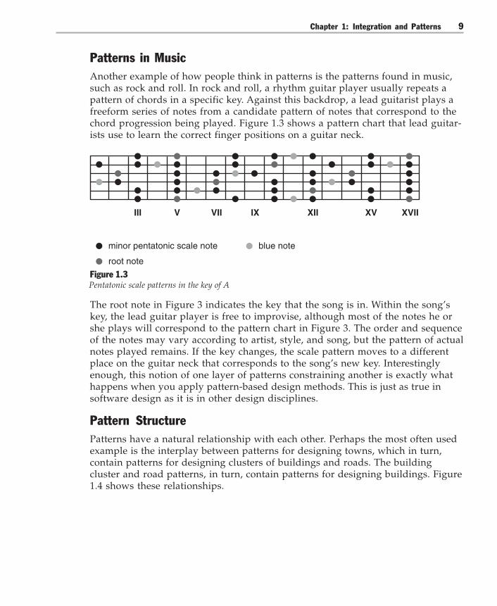
Patterns in MusicAnother example of how people think in patterns is the patterns found in music,such as rock and roll. In rock and roll, a rhythm guitar player usually repeats apattern of chords in a specific key. Against this backdrop, a lead guitarist plays afreeform series of notes from a candidate pattern of notes that correspond to thechord progression being played. Figure 1.3 shows a pattern chart that lead guitar-ists use to learn the correct finger positions on a guitar neck.
minor pentatonic scale note
III V VII IX XII XV XVII
blue note
root note
Figure 1.3Pentatonic scale patterns in the key of A
The root note in Figure 3 indicates the key that the song is in. Within the song’skey, the lead guitar player is free to improvise, although most of the notes he orshe plays will correspond to the pattern chart in Figure 3. The order and sequenceof the notes may vary according to artist, style, and song, but the pattern of actualnotes played remains. If the key changes, the scale pattern moves to a differentplace on the guitar neck that corresponds to the song’s new key. Interestinglyenough, this notion of one layer of patterns constraining another is exactly whathappens when you apply pattern-based design methods. This is just as true insoftware design as it is in other design disciplines.
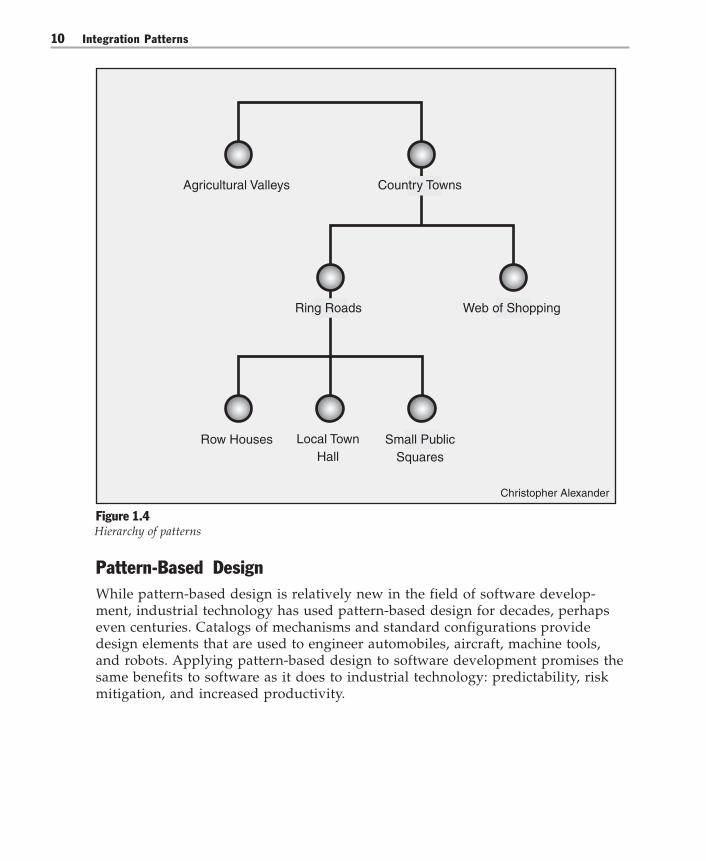
Pattern StructurePatterns have a natural relationship with each other. Perhaps the most often usedexample is the interplay between patterns for designing towns, which in turn,contain patterns for designing clusters of buildings and roads. The buildingcluster and road patterns, in turn, contain patterns for designing buildings. Figure1.4 shows these relationships.
Integration Patterns10
Christopher Alexander
Agricultural Valleys Country Towns
Web of Shopping
Row Houses Small PublicSquares
Ring Roads
Local TownHall
Figure 1.4Hierarchy of patterns
Pattern-Based DesignWhile pattern-based design is relatively new in the field of software develop-ment, industrial technology has used pattern-based design for decades, perhapseven centuries. Catalogs of mechanisms and standard configurations providedesign elements that are used to engineer automobiles, aircraft, machine tools,and robots. Applying pattern-based design to software development promises thesame benefits to software as it does to industrial technology: predictability, riskmitigation, and increased productivity.

Chapter 1: Integration and Patterns 11
Experience is KeyOf course, pattern-based design alone is no guarantee of success in either softwaredesign or industrial technology. Known good mechanisms can be used to buildplanes that do not fly, cars that do not handle well, and applications that do notscale. There is simply no substitute for the skill and experience of designers andengineers in any subject area, and software is no exception. Although patterns helpby offering manageable portions of design knowledge, they are not complete solu-tions by themselves. They still require your skill and experience to tailor them toyour specific requirements.
Applying PatternsApplying patterns to a specific scenario usually involves an iterative design process.As a guiding principle, you want to keep your design as “simple as possible and nosimpler,” as Albert Einstein once said. Although you can use patterns to solve designproblems, make sure that you have a legitimate problem first before applying apattern. Do not use patterns just for the sake of using them.
Although design guidelines and process are related topics (and worthy of dedicatedworks), this book focuses on the tangible outputs of the design process. It focuses inparticular on the role of patterns as they are applied to problems. To examine theconcrete artifacts produced by a pattern-based design process, let’s go back toGlobal Bank and see what came out of the design sessions as the team worked onthe baseline architecture.
Patterns at Global BankThe architecture team analyzed the high-level requirements and constraints pro-vided by the CTO and reviewed existing technical architecture models of the enter-prise. The architecture team also designated several members of the team to do abuild-versus-buy analysis of related commercial off-the-shelf software (COTS)packages that might meet the requirements.
Based on the build-versus-buy analysis, the team decided to build a custom extensibleportal by using commercial platform infrastructure components such as Web serversand database servers, but not to use packaged portal applications. Figure 1.5 showstheir initial approximation of the server types in a network diagram.

Integration Patterns12
DataFirewall
External Partner(SWIFT)
External Partner(Manual Fulfillment)
Customer
SMTP IntegrationServer
Web Server
Firewall
IntegrationServer
NetworkedBank
System
NetworkedBank
System
Payment DirectoryServices
GatewayService
Gateway
Mainframe
CRM
Ethernet
Ethernet
Firewall
Remote Data Center
Data
Figure 1.5Initial network diagram with server types
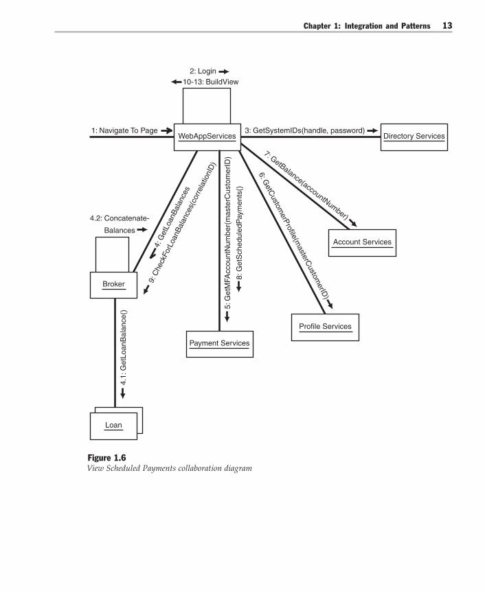
For each key use case, the team determined the sequence of system interactions thatmust occur to fulfill the stated requirements. They described these interactions interms of server types and message sequences. Figure 1.6 shows the View ScheduledPayments use case realization in the form of a collaboration diagram.
Chapter 1: Integration and Patterns 13
9: C
heck
ForL
oanB
alan
ces(
corr
elat
ionI
D)
4: G
etLo
anB
alan
ces
WebAppServices3: GetSystemIDs(handle, password)
8: G
etS
ched
uled
Pay
men
ts()
5: G
etM
FAcc
ount
Num
ber(
mas
terC
usto
mer
ID)
6: GetC
ustomerP
rofile(masterC
ustomerID
)7: GetBalance(accountNumber)4.2: Concatenate-
Balances
4.1:
Get
Loan
Bal
ance
()1: Navigate To Page
2: Login
Directory Services
Account Services
Profile Services
Payment Services
Broker
Loan
10-13: BuildView
Figure 1.6View Scheduled Payments collaboration diagram

Integration Patterns14
The flow of the use case in Figure 1.6 is:1. A customer navigates to the online bill payment application.2. The Web server prompts the customer for a user name and password.3. The Web server authenticates the customer by using information retrieved from
the directory server.4. The Web server sends an asynchronous request to the integration server asking
for related loans.5. The Web server retrieves the customer’s mainframe account number from the
payment server.6. The Web server retrieves customer profile information from the CRM server.7. The Web server retrieves account balance information from the mainframe.8. The Web server retrieves a list of scheduled payments from the payment server.9. The Web server checks the integration server to see whether any loan information
has been retrieved.10. The Web server builds the presentation, which displays account balance, sched-
uled payments, and customer profile information.11. If loan information is available, it appends this optional information onto the
presentation.12. The Web server returns the presentation code back to the browser.13. The browser renders the view.
This use case realization is a representative sample of the bill payment application’ssignificant use cases. The team took a similar approach to analyze other use cases,identify server types, and design message interactions. To create these use caserealizations, the team conducted a series of iterations, each beginning with a designsession using class-responsibility-collaboration (CRC) style techniques. Althoughsimilar in nature to CRC sessions, these sessions were not limited to class-levelabstractions. Often these sessions involved subsystems, server types, processes, andchannels as well.
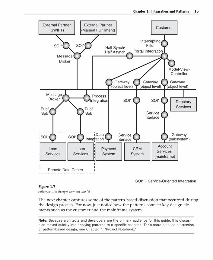
The team’s goal, as they considered the necessary collaborations between elements,was to design the simplest system that would satisfy all current requirements andaccount for system constraints. While working through the alternatives, they relied onthe language of patterns to provide a common vocabulary for the team. Patterns werealso useful as a concise way to communicate the context, forces, and tradeoffs in-volved in each design decision. At times, they realized that certain patterns onlyadded complexity to the design, so they eliminated those patterns.
As they completed each iteration, they created a pattern model of the system torecord their decisions. The model from the last iteration is shown in Figure 1.7. Thispattern model represented the simplest system that realized the target use cases andconstraints. To keep their models simple, they represented patterns as circles andadded other high-level design elements to the model to communicate the overalldesign.
Chapter 1: Integration and Patterns 15
External Partner(SWIFT)
SOI*
External Partner(Manual Fulfillment)
Customer
LoanServices
CRMSystem
PaymentSystem
Model-View-Controller
SOI*
SOI*
ServiceInterface
Gateway(subsystem)
MessageBroker
SOI*
SOI* = Service-Oriented Integration
Remote Data Center
Half Synch/ Half Asynch
Gateway(object level)
Gateway(object level)
Gateway(object level)
SOI*
Pub/Sub
MessageBroker
ProcessIntegration
Pub/Sub
SOI*
ServiceInterface
InterceptingFilter
Portal Integration
LoanServices
DirectoryServices
AccountServices
(mainframe)
DataIntegration
Figure 1.7Patterns and design element model
The next chapter captures some of the pattern-based discussion that occurred duringthe design process. For now, just notice how the patterns connect key design ele-ments such as the customer and the mainframe system.
Note: Because architects and developers are the primary audience for this guide, this discus-sion moved quickly into applying patterns to a specific scenario. For a more detailed discussionof pattern-based design, see Chapter 7, “Project Notebook.”

Integration Patterns16
The next step was to map these patterns to an implementation technology and toiterate again. In this case, many of the platform decisions were already made, andthese platform decisions constrained the design choices. Sometimes, the implemen-tation constraints forced the team to reconsider their design, and they adjustedaccordingly. When they finished, they produced the platform-level implementationdiagram shown in Figure 1.8.
Customer
Model-View-Controller
SOI*
ServiceInterface
Gateway(subsystem)SOI*
SOI* = Service-Oriented Integration
Half Synch/ Half Asynch
Gateway(object level)
Gateway(object level)
Gateway(object level)
SOI*
SOI*
InterceptingFilter
Portal Integration
ASP.NET &.NET Framework
IBM OS390MicrosoftCRM?
SQL Server(Yukon)
Pub/Sub
MessageBroker
ProcessIntegration
Pub/Sub
Remote Data Center
BizTalk Server 2004
External Partner(SWIFT)
SOI*
External Partner(Manual Fulfillment)
SOI*
MessageBroker
BizTalk Server 2004
ServiceInterface
Host IntegrationServer 2004
.NET Framework
DataIntegration
IBM WebSphere J2EE
Active Directory
Figure 1.8Pattern diagram mapped to implementation technology
Chapter 1: Integration and Patterns 17
Figure 1.8 shows that the Global Bank integration architecture is composed ofnumerous pattern-based design elements implemented on the Microsoft platform.To trace the implementation of these elements down to running bits, refer to theappropriate implementation pattern later in this guide. For example, to understandhow to implement the gateway to the mainframe, refer to Implementing Gateway withHost Integration Server 2004. This pattern includes the details associated with con-necting Global Bank’s .NET Framework portal application with their existingCOBOL-based CICS transactions.
Next ChapterThis chapter introduced the Global Bank scenario that is used throughout this guideand briefly discussed how patterns can help development teams find workableanswers to integration challenges. The next chapter uses the language of patterns toexplore the decisions and tradeoffs that the Global Bank architecture team madewhile designing and implementing their bill payment system.


2Using Patterns to Design the BaselineArchitecture
“It’s all talk until the code runs.” — Ward Cunningham
The last chapter introduced a banking scenario that posed many technical integra-tion challenges. It also presented patterns as an effective means of communicatingdesign decisions. This chapter walks though the application of integration patternsin the context of the Global Bank scenario.
Although the scenario is a fictitious story for conveying design decisions, it isimportant to note that the authors actually built and performance tested thisdesign in the patterns & practices lab at Microsoft. The design team consisted of field-experienced practitioners with access to the latest product builds. The decisionpoints in the story correspond to real decision points in the lab, although this de-scription shapes them into a more readable story than the actual effort. Also, theactual development process was more iterative than the story might suggest; someportions of the system evolved incrementally. Later in this guide, you will find thatthe implementation patterns contain extracts of the code used to run the GlobalBank baseline architecture. You will also find more detailed explanations of thepatterns mentioned in this chapter.
Meeting the Requirements of Global BankAt the end of the last chapter, the Global Bank architecture team applied a pattern-based design approach to its bill payment system’s requirements and arrived at aninitial technical architecture blueprint. At this point, the team felt fairly satisfiedabout the initial design, at least on paper. The members of the team knew the valueof creating these design models, but they also knew that they would learn otherthings only from the running code. They were anxious to validate their models withexecutable bits.

Integration Patterns20
To validate their thinking, the members of the Global Bank team built a baselinearchitecture in the test lab and implemented five of the most architecturally signifi-cant use cases. They chose these particular use cases to help define and validate themost important mechanisms in the design. They did not intend the use cases to befunctionally complete — that would come later when the functional requirementsfirmed up. At this point, they wanted to refine the riskiest parts of their designdown to the level of executable code, the most concrete form of design.
As they implemented this baseline architecture, members of the team also perfor-mance tested many parts of the system to validate their design assumptions andtradeoffs. This helped them to further understand the overall scalability of theirsolution as they considered the impact of additional users over time. All of thisimplementation and testing contributed to their overall confidence in the patternsthey had selected.
The bulk of this chapter explores the decisions and tradeoffs that the Global Bankarchitecture team made during the design and implementation process, and it takesa closer look at the implemented system. The discussion uses the language of pat-terns to convey these decisions and tradeoffs, as well as the intentions behind them,as discrete and comprehensible decision points. Throughout the discussion, patternnames appear in title capitalization and italic (for example, Portal Integration). Thistreatment of pattern names emphasizes the building of a pattern vocabulary andsignals that the concepts are explained as patterns later in this guide.
Using Patterns to Communicate Design DecisionsEach pattern clearly limits the scope of its problem and solution to a discrete andcomprehensible, or “mind-sized,” decision point. By considering relatively smallatomic design decisions one at a time, you are better prepared to manage the overallcomplexity of the system. As you build a complex system, you aggregate thesesmall design decisions together to eventually form a larger hierarchy, or frame, ofdecisions.
Of course, changes at the top of the hierarchy may affect the elements below, and itis unrealistic to expect your first design to be just right. Most likely, you will need toiterate. However, having a set of discrete decision points makes it easier to iteratewhen you need to.
Remember, in complex environments, there is often no single right answer for agiven problem. For any set of requirements, each group of designers may arrive atdifferent, yet equally valid, designs. Usually, the difference reflects a different set oftradeoffs and priorities. What is most important to understand about the designprocess is that:

Chapter 2: Using Patterns to Design the Baseline Architecture 21
● A series of technical decisions must be made.● Each design decision involves tradeoffs — both advantages and disadvantages.● Tradeoffs made at one level constrain the decisions at other levels.● The sum of these design decisions must result in an architecture that meets both
the functional and nonfunctional requirements of the system.
With these guidelines in mind, the architecture team set out to build a baselinearchitecture.
The Role of a Baseline ArchitectureA baseline architecture is a thin executable slice through the overall system that isdesigned to implement the most architecturally significant use cases. As you imple-ment these key use cases, you want to define the key mechanisms and componentsin the system and retire the most serious technical risks early. If you do this well, thebaseline architecture does not become a prototype to be thrown away. Instead, itbecomes the skeletal structure of the system. The baseline provides sufficient stabil-ity so that subsequent iterations can smoothly evolve the running system into onethat meets all of the functional and nonfunctional requirements. The baseline archi-tecture is intentionally incomplete.
How do you actually design a baseline architecture? To answer this question, let’strace the architecture team’s steps during the design sessions.
Designing the Global Bank Baseline ArchitectureAs the team dissected the high-level requirements of the chief technology officer(CTO), the members of the team arrived at the following use cases:● Schedule Payments● View Scheduled Payments● Execute Scheduled Payment● Receive Payment Response● Add Payee
The first use case they discussed was the View Scheduled Payments use case. Thisuse case involved a portal that allowed users to see their account information,including their current account balance and a list of scheduled payments. To buildthis portal, the team would need to connect to multiple back-end systems and toaggregate the results in a single view. Implementing this use case would require theteam to resolve several key technical issues. Let’s look now at the use case in moredetail and understand the team’s thinking as they approached the problem.
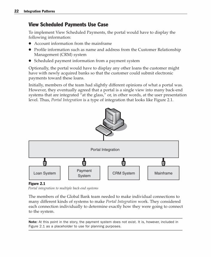
Integration Patterns22
View Scheduled Payments Use CaseTo implement View Scheduled Payments, the portal would have to display thefollowing information:● Account information from the mainframe● Profile information such as name and address from the Customer Relationship
Management (CRM) system● Scheduled payment information from a payment system
Optionally, the portal would have to display any other loans the customer mighthave with newly acquired banks so that the customer could submit electronicpayments toward these loans.
Initially, members of the team had slightly different opinions of what a portal was.However, they eventually agreed that a portal is a single view into many back-endsystems that are integrated “at the glass,” or, in other words, at the user presentationlevel. Thus, Portal Integration is a type of integration that looks like Figure 2.1.
Loan SystemPaymentSystem
CRM System Mainframe
Portal Integration
Figure 2.1Portal integration to multiple back-end systems
The members of the Global Bank team needed to make individual connections tomany different kinds of systems to make Portal Integration work. They consideredeach connection individually to determine exactly how they were going to connectto the system.
Note: At this point in the story, the payment system does not exist. It is, however, included inFigure 2.1 as a placeholder to use for planning purposes.

Chapter 2: Using Patterns to Design the Baseline Architecture 23
System ConnectionsAs the members of the team thought more about this problem, they debated thekinds of connections they could make. The discussion was full of overloaded termsand individual biases toward the methods that each member was most familiarwith. To make matters worse, the team did not share a common design vocabularybecause some members of the team had never worked together before.
Finally, the members of the team realized they had to narrow the discussion to a fewpractical choices for each system. To do so, they would have to tighten their frame ofreference when they compared their connection options. They finally agreed toapproach the problem from the perspective of integrating by using a Three-LayeredServices Application [Trowbridge03]. As shown in Figure 2.2, a Three-Layered ServicesApplication defines three distinct logical layers: data, business logic (functional), andpresentation.
Data Layer
PresentationLayer
Business Logic Layer
Figure 2.2Three-Layered Services Application
They also agreed that although not every system was designed as a Three-LayeredServices Application, using these three logical layers would give them a common wayto reason about other systems. Using these layers to shape their discussion, theybegan to discuss the relative tradeoffs between each connection alternative.
Note: To present an overview of the design, this chapter discusses tradeoffs between designalternatives at a high level only. For more detailed information regarding these tradeoffs, seethe pattern chapters (Chapters 3 through 6). If you want to see a visual model of all of thesepatterns and their relationships, see Chapter 7, “Project Notebook”
Integration Patterns24
First, they could use Data Integration to connect at the logical level of data, makingthe same data available to more than one application. This approach worked wellwhen there was very little business logic to reuse across applications. For otherapplications, they knew that raw data was not enough; they wanted to reuse thefunctionality of a given application. This functionality often contained businesslogic, process, or calculated values. In this case, they would need to use FunctionalIntegration to connect at the business logic layer. And although they preferred toconnect to systems directly to share either function or data, they acknowledged thatsometimes the only practical way to integrate with a system was through Presenta-tion Integration, also known as screen scraping. Moving away from a pure systemsperspective, they also discussed human integration as a means to integrate with asystem. However, because they were focused on building a baseline architecture,they considered human integration to be out of scope — at least for the moment.
Now that they agreed on an approach to the alternatives before them, the membersof the team returned to the set of individual connection decisions they had to make.The first system to connect to was the payment system.
Connecting to the Payment System
The members of the team knew they would need a system to hold all the scheduledpayments along with related information. They decided the simplest thing to do wasto build a payment system that persisted this information in a database with Web-based administrator screens to manage the data. They decided to use Data Integra-tion to connect the portal to the payment system because no additional systemfunctionality or behavior seemed important to share.
Connecting to the CRM System
The next system to connect to was the existing CRM system. The members of theteam analyzed the system architecture and realized there was only one practicalchoice: Functional Integration. That is because the software vendor used a highlyabstracted schema within a relational database to store information and recom-mended against Data Integration. Instead, the vendor provided a functional Webservices interface to encapsulate access to the data. This was the same kind ofencapsulation at a system level that good object-oriented designers perform at aclass level when they create private instance variables and public accessormethods.
Although encapsulation is generally a good thing, in this case the members of theteam marked it as a technical risk. They marked it as a risk because the vendor’simplementation was effectively “black box,” or unknown to the Global Bank team.The members of the team also knew from experience how difficult it is to build highperformance abstract interfaces. Furthermore, because profile information from theCRM was required with each View Scheduled Payments request, performance wascritical. They decided to mark this interface as a key test point and to stress test it

Chapter 2: Using Patterns to Design the Baseline Architecture 25
early to discover the point where additional load would compromise system perfor-mance. They needed this information soon so they could consider compensatingdesign alternatives, if necessary.
Connecting to the Mainframe
Integrating with the mainframe was critical because it was the system of record forall account information. Over the years, the organization had invested significantlyto develop solid Customer Information Control System (CICS) transactions. Anyintegration with the account system would need to use this functionality; therefore,the team chose Functional Integration but deferred the connection details until later.
The team created the diagram in Figure 2.3 to record the design decisions made sofar. The team used squares to represent design elements, circles to represent pat-terns, and lines to indicate relationships between the patterns and other designelements.
Customer
CRMSystem
PaymentSystem
FunctionalIntegration
FunctionalIntegration
DataIntegration
Portal Integration
AccountServices
(mainframe)
Figure 2.3Connecting the payment, CRM, and mainframe systems to a portal
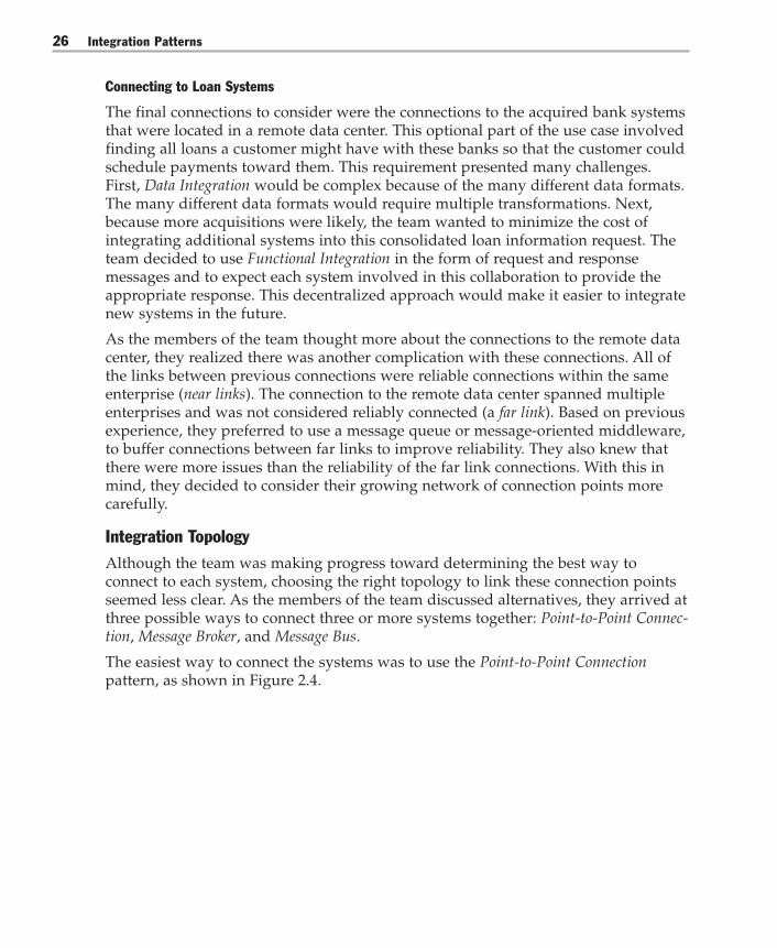
Integration Patterns26
Connecting to Loan Systems
The final connections to consider were the connections to the acquired bank systemsthat were located in a remote data center. This optional part of the use case involvedfinding all loans a customer might have with these banks so that the customer couldschedule payments toward them. This requirement presented many challenges.First, Data Integration would be complex because of the many different data formats.The many different data formats would require multiple transformations. Next,because more acquisitions were likely, the team wanted to minimize the cost ofintegrating additional systems into this consolidated loan information request. Theteam decided to use Functional Integration in the form of request and responsemessages and to expect each system involved in this collaboration to provide theappropriate response. This decentralized approach would make it easier to integratenew systems in the future.
As the members of the team thought more about the connections to the remote datacenter, they realized there was another complication with these connections. All ofthe links between previous connections were reliable connections within the sameenterprise (near links). The connection to the remote data center spanned multipleenterprises and was not considered reliably connected (a far link). Based on previousexperience, they preferred to use a message queue or message-oriented middleware,to buffer connections between far links to improve reliability. They also knew thatthere were more issues than the reliability of the far link connections. With this inmind, they decided to consider their growing network of connection points morecarefully.
Integration TopologyAlthough the team was making progress toward determining the best way toconnect to each system, choosing the right topology to link these connection pointsseemed less clear. As the members of the team discussed alternatives, they arrived atthree possible ways to connect three or more systems together: Point-to-Point Connec-tion, Message Broker, and Message Bus.
The easiest way to connect the systems was to use the Point-to-Point Connectionpattern, as shown in Figure 2.4.
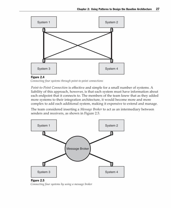
Chapter 2: Using Patterns to Design the Baseline Architecture 27
System 3
System 1
System 4
System 2
Figure 2.4Connecting four systems through point-to-point connections
Point-to-Point Connection is effective and simple for a small number of systems. Aliability of this approach, however, is that each system must have information abouteach endpoint that it connects to. The members of the team knew that as they addedmore systems to their integration architecture, it would become more and morecomplex to add each additional system, making it expensive to extend and manage.
The team considered inserting a Message Broker to act as an intermediary betweensenders and receivers, as shown in Figure 2.5.
System 3
System 1
System 4
System 2
Message Broker
Figure 2.5Connecting four systems by using a message broker
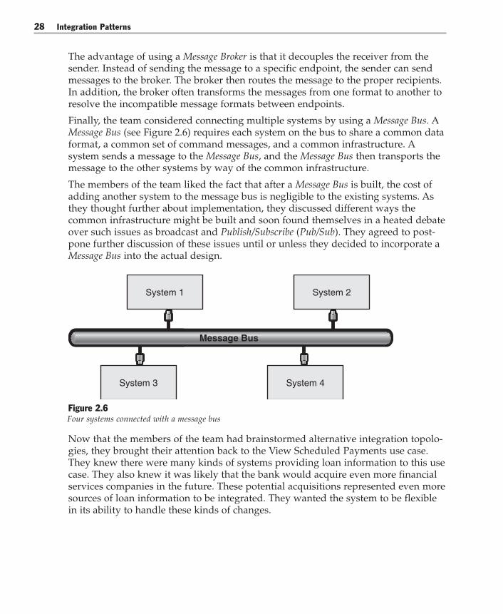
Integration Patterns28
The advantage of using a Message Broker is that it decouples the receiver from thesender. Instead of sending the message to a specific endpoint, the sender can sendmessages to the broker. The broker then routes the message to the proper recipients.In addition, the broker often transforms the messages from one format to another toresolve the incompatible message formats between endpoints.
Finally, the team considered connecting multiple systems by using a Message Bus. AMessage Bus (see Figure 2.6) requires each system on the bus to share a common dataformat, a common set of command messages, and a common infrastructure. Asystem sends a message to the Message Bus, and the Message Bus then transports themessage to the other systems by way of the common infrastructure.
The members of the team liked the fact that after a Message Bus is built, the cost ofadding another system to the message bus is negligible to the existing systems. Asthey thought further about implementation, they discussed different ways thecommon infrastructure might be built and soon found themselves in a heated debateover such issues as broadcast and Publish/Subscribe (Pub/Sub). They agreed to post-pone further discussion of these issues until or unless they decided to incorporate aMessage Bus into the actual design.
System 1
System 3 System 4
System 2
Message Bus
Figure 2.6Four systems connected with a message bus
Now that the members of the team had brainstormed alternative integration topolo-gies, they brought their attention back to the View Scheduled Payments use case.They knew there were many kinds of systems providing loan information to this usecase. They also knew it was likely that the bank would acquire even more financialservices companies in the future. These potential acquisitions represented even moresources of loan information to be integrated. They wanted the system to be flexiblein its ability to handle these kinds of changes.
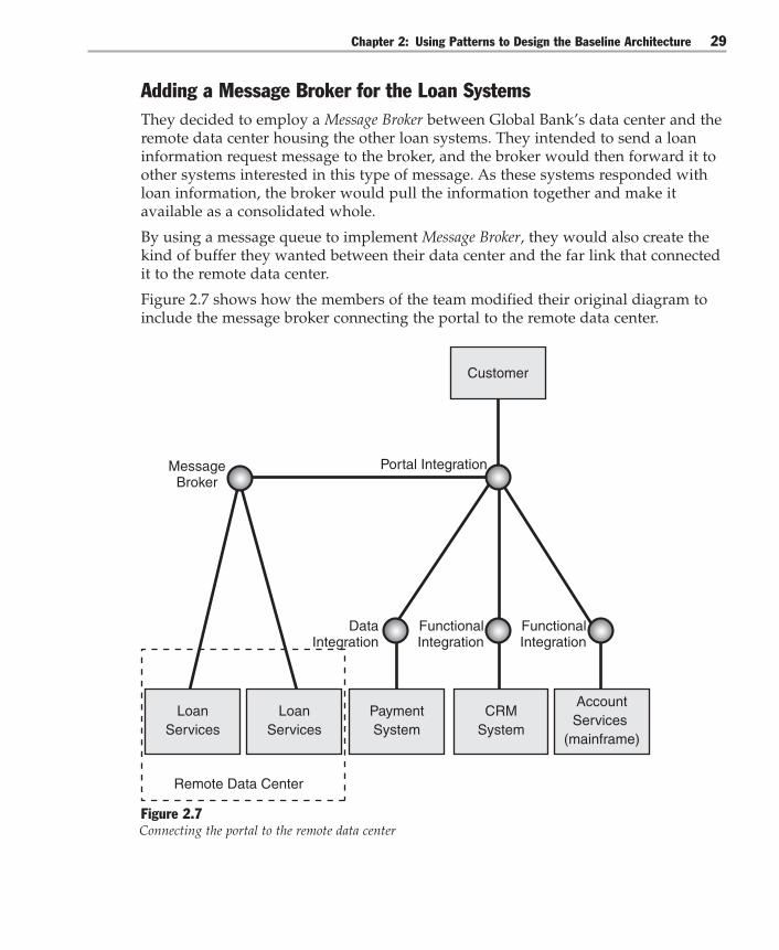
Chapter 2: Using Patterns to Design the Baseline Architecture 29
Adding a Message Broker for the Loan SystemsThey decided to employ a Message Broker between Global Bank’s data center and theremote data center housing the other loan systems. They intended to send a loaninformation request message to the broker, and the broker would then forward it toother systems interested in this type of message. As these systems responded withloan information, the broker would pull the information together and make itavailable as a consolidated whole.
By using a message queue to implement Message Broker, they would also create thekind of buffer they wanted between their data center and the far link that connectedit to the remote data center.
Figure 2.7 shows how the members of the team modified their original diagram toinclude the message broker connecting the portal to the remote data center.
Remote Data Center
Customer
LoanServices
CRMSystem
PaymentSystem
MessageBroker
FunctionalIntegration
FunctionalIntegration
DataIntegration
Portal Integration
LoanServices
AccountServices
(mainframe)
Figure 2.7Connecting the portal to the remote data center

Integration Patterns30
To show the dynamic nature of the system and to document how the system wouldrealize the View Scheduled Payments use case, the team drew the collaborationdiagram that is shown in Figure 2.8.
9: C
heck
ForL
oanB
alan
ces(
corr
elat
ionI
D)
4: G
etLo
anB
alan
ces
WebAppServices3: GetSystemIDs(handle, password)
8: G
etS
ched
uled
Pay
men
ts()
5: G
etM
FAcc
ount
Num
ber(
mas
terC
usto
mer
ID)
6: GetC
ustomerP
rofile(masterC
ustomerID
)
7: GetBalance(accountNumber)4.2: Concatenate-
Balances
4.1:
Get
Loan
Bal
ance
()
1: Navigate To Page
2: Login
Directory Services
Account Services
Profile Services
Payment Services
Broker
Loan
10-13: BuildView
Figure 2.8View Scheduled Payments collaboration diagram
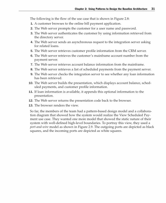
Chapter 2: Using Patterns to Design the Baseline Architecture 31
The following is the flow of the use case that is shown in Figure 2.8:1. A customer browses to the online bill payment application.2. The Web server prompts the customer for a user name and password.3. The Web server authenticates the customer by using information retrieved from
the directory server.4. The Web server sends an asynchronous request to the integration server asking
for related loans.5. The Web server retrieves customer profile information from the CRM server.6. The Web server retrieves the customer’s mainframe account number from the
payment server.7. The Web server retrieves account balance information from the mainframe.8. The Web server retrieves a list of scheduled payments from the payment server.9. The Web server checks the integration server to see whether any loan information
has been retrieved.10. The Web server builds the presentation, which displays account balance, sched-
uled payments, and customer profile information.11. If loan information is available, it appends this optional information to the
presentation.12. The Web server returns the presentation code back to the browser.13. The browser renders the view.
So far, the members of the team had a pattern-based design model and a collabora-tion diagram that showed how the system would realize the View Scheduled Pay-ment use case. They wanted one more model that showed the static nature of theirsystem with well-defined high-level boundaries. To portray this view, they used aport-and-wire model as shown in Figure 2.9. The outgoing ports are depicted as blacksquares, and the incoming ports are depicted as white squares.

Integration Patterns32
[Set Loan Info]
[Get Loan Balances]
Integration Services
[Get System IDs]
Directory Services(Directory Server)
[Get Other Loans]
Loan Services (acquired
bank’s systems)
[Get Other Loans]
Loan Services (acquired
bank’s systems)
Gateway
BusinessLogic
Presentation
Customer
[View ScheduledPayments]
Web/App Services
[Get CustomerProfile Information]
Profile Services(CRM System)
[Get Account Balance]
Account Services(Mainframe)
[Get Mainframe Acct No]
[Get Scheduled Payments]
Payment Services (Payment System)
Data
Data Data Data
Figure 2.9View Scheduled Payments message flow

Chapter 2: Using Patterns to Design the Baseline Architecture 33
Although all the details were certainly not worked out for this use case, the mem-bers of the team felt that the use case was at a sufficient level of detail to proceed tothe next use case. They would return to refine the design later, after exploringwhether parts of this design would realize other use cases as well.
Execute Scheduled Payment Use CaseThe next use case they considered was the Execute Scheduled Payment use case. Toimplement this use case, the system would:● Start up at a system-defined interval.● Retrieve the set of payments to be made on or before the current date.● For each payment, the system would verify that there were sufficient funds in the
payment account and then debit the account for the payment amount.● Send the payment to an appropriate payment channel.
There were four kinds of payment channels currently in scope: domestic paymentsthrough a clearing house, electronic payment gateways using Society for WorldwideInterbank Financial Telecommunication (SWIFT) transactions, electronic paymentsto a manual fulfillment house, and account-to-account transfers within the bank’sinternal system.
Focusing on the Baseline ArchitectureAs the members of the team talked though this use case, they tried to avoid discuss-ing domain-specific details that had more to do with business logic than technicalarchitecture. Although they knew these details were important, they also realizedthat the purpose of the baseline architecture was to mitigate technical risk, not tofully refine the business requirements. They knew the requirements team was ontrack to do exactly that job, so they focused on the items that worried them the mostfrom a technical perspective. They also deemphasized some of the use case areasthat did not represent top technical challenges.
Payment ChannelsOne area of concern was the SWIFT payment Gateway.
Note: The Gateway pattern abstracts access to an external resource by presenting a singleinterface to the integrated applications while hiding the external resource interface. For moreinformation, see “Gateway” later in this chapter.
Integration Patterns34
The members of the team knew the requirements would include making interna-tional transactions to support their wealthiest clients, and for this they would useSWIFT transactions. They also knew there would be requirements for domesticpayments, and for those payments they would use the existing system. It would betoo expensive to pay a SWIFT transaction fee for domestic payments, especiallywhen they already had an existing payment system.
The existing payment system was technically straightforward. It used a leasedsecure line for Point-to-Point Connection with a clearing house and secure file trans-fer. The bank and the clearing house exchanged files that contained both outgoingand incoming data records. This was a simple form of Data Integration that the bankhad used for years. The team would use this system for domestic transfers. Becausethey understood it well, there was little reason to build and test this system early, sothese details were omitted from the initial use case.
However, the SWIFT payment Gateway was a very different story. They would needto package the transaction securely in an XML message and use Web services to sendit to the payment Gateway over the Internet. Because this part of the use case wasnew to the team and presented many technical risks, it was one of the top priorities forthe baseline architecture. They wanted to build it early and test it.
Using Domain Knowledge to Guide Design DecisionsBecause many members of the team had been in banking for years, they naturallybrought their business knowledge into the design sessions. Although this businessknowledge was invaluable, the team had to sort out what was relevant for thebaseline architecture and what was not. This sorting was, of course, a judgment call,but it was necessary for the team to stay focused on mitigating the most importanttechnical risks first.
For example, the members of the team knew that any time the bank would initiate apayment through an external party such as a clearing house or a payment Gateway,the confirmation would be delayed. The rules of double entry accounting would notallow funds to be in limbo during this period. Therefore, a holding account wouldhave to be credited at payment initiation and debited upon payment confirmation.This would keep the system in balance at all times.
Although implementing a holding account was critical to the final use case, it wasnot critical for the early baseline architecture. The team was proficient at enlistingdebits and credits in the same transactions across most of the systems in the bank.They did not consider this to be a technical risk. Therefore, the team decided to deferthe implementation of this logic until after the requirements team defined thespecific holding accounts to use.

Chapter 2: Using Patterns to Design the Baseline Architecture 35
Using SWIFT Gateway for the Baseline ArchitectureThe rules to determine the right payment channel were straightforward. When acustomer scheduled a payment, the customer could select either a domestic or aninternational payment. If the payment were domestic, the customer would providean American Bankers Association (ABA) routing number for the intended payee. Ifthis field were left blank, the system would send an electronic payment to a com-pany that specialized in paper check writing and mailing services (a manual fulfill-ment house). If the field were not blank, the system would check the routing numberagainst a list of internal banks. If the numbers matched, the system would make apayment by transferring money internally from one account to another. If therouting number were valid but did not match the internal banks, the standarddomestic payments system would make the payment by secure file transfer. Finally,payments marked as international would use the SWIFT payment Gateway. Becausethe system would send the payment to an appropriate channel, there would be asystem-based acknowledgment that the message was received.
To simplify the initial use case, the members of the team omitted any routing to theirdomestic payment system and instead routed these payments through the SWIFTGateway for test purposes. This exercised the SWIFT Gateway by using the test data.The test data was based on domestic accounts instead of international accounts. Itwould be easy to add international routing and test data later, but they wanted topressure test the Gateway payment mechanisms early.
As they continued to walk though the use case flow, the members of the teamrealized that a key element was missing. Currently, the system would receive anacknowledgment that the payment message was sent, but how would the systemknow if the payment was received by the intended payee? What would happen ifthe payment Gateway or manual fulfillment house could not pay the payee? Thesequestions led them to the Receive Payment Response use case.
Designing for Execute Scheduled Payment and Receive PaymentResponseThe Receive Payment Response use case described the behavior of the paymentGateway and the manual fulfillment house after they processed the payment request.In this use case, these payment channels returned the result of their processing toGlobal Bank’s system. If the payment was successful, the payment status and trans-action ID were updated in the payment system. If the payment failed, a compensat-ing transaction to credit the account was first issued to the mainframe and thenstatus and ID fields were updated accordingly in thepayment system.

Integration Patterns36
Because of the close relationship between Execute Scheduled Payments and ReceivePayment Response, the team decided to evaluate Process Integration for both usecases.
Process IntegrationProcess Integration adds a layer of software on top of other applications and servicesto coordinate the execution of a long-running business function, as shown in Figure2.10.
SWIFTGateway
ManualFulfillment
Partner
PaymentSystem
Internal BankSystem
Process Integration
Figure 2.10Process Integration, a coordinating layer above other applications and services
The members of the team knew they would need a layer like this to coordinate thetwo use cases, and they discussed the best way to design it. Some members of theteam suggested an integration server. Integration servers often include orchestrationtools for this purpose. Other members of the team wanted to build a custom coordi-nating layer by encapsulating process and activity components. They thought theintegration server was excessive. After some debate, they decided to choose theintegration server approach. They reasoned it was likely that the bank would con-tinue to add more financial services and external partners in the future, and thatthese services and partners would need Process Integration capabilities also. Andalthough the use of an integration server might initially cost them some time forinstallation and training, the cost would be more than repaid through the reduceddevelopment time and overall flexibility of the system.
The members of the team updated their design model to incorporate Process Integra-tion, as shown in Figure 2.11. Notice that process integration needs to communicatewith the message broker and the payment systems, but it does not need to connectdirectly to the portal.
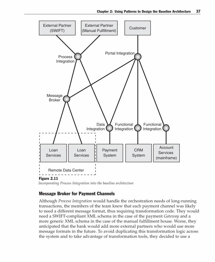
Chapter 2: Using Patterns to Design the Baseline Architecture 37
Remote Data Center
External Partner(SWIFT)
External Partner(Manual Fulfillment)
Customer
LoanServices
CRMSystem
PaymentSystem
ProcessIntegration
MessageBroker
FunctionalIntegration
FunctionalIntegration
DataIntegration
Portal Integration
LoanServices
AccountServices
(mainframe)
Figure 2.11Incorporating Process Integration into the baseline architecture
Message Broker for Payment ChannelsAlthough Process Integration would handle the orchestration needs of long-runningtransactions, the members of the team knew that each payment channel was likelyto need a different message format, thus requiring transformation code. They wouldneed a SWIFT-compliant XML schema in the case of the payment Gateway and amore generic XML schema in the case of the manual fulfillment house. Worse, theyanticipated that the bank would add more external partners who would use moremessage formats in the future. To avoid duplicating this transformation logic acrossthe system and to take advantage of transformation tools, they decided to use a

Integration Patterns38
Message Broker as an intermediary between Global Bank’s system and their tradingpartners’ systems.
Like the other Message Broker in this design, the queue-based message broker imple-mentation would buffer the somewhat unreliable connections between systems.
Message Broker Using Functional Integration with SOIEven though they decided to use a message broker to communicate with tradingpartners, they still had to decide how to connect the Message Broker to the targetsystem. Message Brokers can use Data Integration to connect at the logical data layer.For example, Message Brokers can connect at the logical data level by sending files byusing File Transfer Protocol (FTP). Or, Message Brokers can use Functional Integrationto connect at the business logic layer. For example, they can connect by using Webservices.
The members of the team knew there were many ways to share functionality. Thethree most common methods are distributed objects (.NET Framework remoting,COM+, Common Object Request Broker Architecture (CORBA)), Remote MethodInvocation (RMI); proprietary message-oriented middleware, and Web services.Some of the team members came from large enterprises where they had built logicalservices on top of proprietary message-oriented middleware. This approach had hadworked well for them in the past. However, all the members of the team wereintrigued by the possibility of using Web services because of the potentialinteroperability between platforms and the support of major platform vendors. Notsurprisingly, they decided to connect with partners by using a kind of FunctionalIntegration based on Web services: Service-Oriented Integration (SOI).
To record their design decisions, the members team modified their design model toinclude an additional message broker and the use of Service-Oriented Integration, asshown in Figure 2.12. They also rationalized the communication lines with a com-mon bus to make the model more readable.

Chapter 2: Using Patterns to Design the Baseline Architecture 39
SOI* = Service-Oriented Integration
Remote Data Center
External Partner(SWIFT)
SOI*
External Partner(Manual Fulfillment)
Customer
LoanServices
CRMSystem
PaymentSystem
SOI*
MessageBroker
MessageBroker Process
Integration
FunctionalIntegration
FunctionalIntegration
DataIntegration
Portal Integration
LoanServices
AccountServices
(mainframe)
Figure 2.12Incorporating Message Broker and Service-Oriented Integration for connections with trading partners
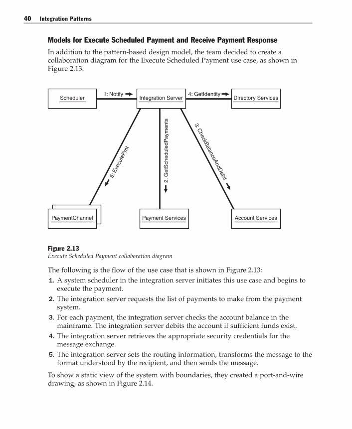
Integration Patterns40
Models for Execute Scheduled Payment and Receive Payment ResponseIn addition to the pattern-based design model, the team decided to create acollaboration diagram for the Execute Scheduled Payment use case, as shown inFigure 2.13.
3: CheckB
alanceAndD
ebit5: E
xecu
teP
mt
4: GetIdentity1: NotifyScheduler Integration Server Directory Services
2. G
etS
ched
uled
Pay
men
ts
PaymentChannel Payment Services Account Services
Figure 2.13Execute Scheduled Payment collaboration diagram
The following is the flow of the use case that is shown in Figure 2.13:1. A system scheduler in the integration server initiates this use case and begins to
execute the payment.2. The integration server requests the list of payments to make from the payment
system.3. For each payment, the integration server checks the account balance in the
mainframe. The integration server debits the account if sufficient funds exist.4. The integration server retrieves the appropriate security credentials for the
message exchange.5. The integration server sets the routing information, transforms the message to the
format understood by the recipient, and then sends the message.
To show a static view of the system with boundaries, they created a port-and-wiredrawing, as shown in Figure 2.14.

Chapter 2: Using Patterns to Design the Baseline Architecture 41
[Pay Item]
Payment Gateway(SWIFT)
[Get Identity]
Directory Services(Directory Server)
[Pay Item]
Account Services (acquired
bank’s systems)
[Pay Item]
Manual Fulfillment
ExecutePayment
SendPayment
[Send Payment] Integration Services
[Set Payment Status]
[Check Balance + Debit]
Account Services(Mainframe)
[Get Scheduled Payments]
Payment Services (Payment System)
Data
Data Data
TransformMessage
Set PaymentRouting
Figure 2.14Execute Scheduled Payment use case realization

Integration Patterns42
Because the Receive Payment Response use case was related to the View ScheduledPayments use case, the team created a collaboration diagram for this use case, asshown in Figure 2.15.
4: SetStatus
5: UpdateStatus
Payment ServicesPaymentChannel
2: SendPayment-Response
1: ProcessPayment3: CorrelateResponse
Integration Services
Figure 2.15Receive Payment Response collaboration diagram
The following is the flow of the use case that is shown in Figure 2.15:1. The precondition for this use case is that a payment message has been sent to one
of the payment recipients: the SWIFT payment gateway, the manual fulfillmentpartner, or an acquired bank.
2. After processing the payment request, the payment recipient sends a paymentresponse to the integration server.
3. The integration server correlates the response to the originating request.4. If the payment failed, the integration server credits the customer account on the
mainframe.5. The integration server updates the payment record in the payment system with
status and transaction ID.
Just as they did for the previous use case, the members of the team also produced aport-and-wire diagram for Receive Payment Response, as shown in Figure 2.16.

Chapter 2: Using Patterns to Design the Baseline Architecture 43
[Receive PaymentResponse]
Integration Services
[Send PaymentResponse]
Payment Gateway(SWIFT)
[Send PaymentResponse]
Account Services (acquired
bank’s systems)
Manual Fulfillment
[Credit Account]
Account Services(Mainframe)
[Set Payment Status]
Payment Services (Payment System)
Data Data
[Send PaymentResponse]
Figure 2.16Receive Payment Response use case realization
Integration Patterns44
Accessing Account Services on the MainframeAs the members of the team reviewed the Receive Payment Response use case, theyrealized there was still a key issue to resolve. Both this use case and the View Sched-uled Payments use case needed to access the mainframe by using Functional Integra-tion, although exactly how that was going to be done was still unclear. There wereclear differences in application programming and potential differences in networkprotocols that had to be resolved, not to mention security and transactions. Howwould the team manage this complexity and not let it overcomplicate the design?One team member suggested a Gateway.
GatewayA Gateway is a design element that encapsulates outbound access to an externalsystem. There are Gateways at the application level that are usually implemented asclasses. For more information, see Enterprise Solution Patterns Using Microsoft .NET[Trowbridge03] or Martin Fowler’s Patterns of Enterprise Application Architecture[Fowler03]. There are also Gateways at the integration level that are usually imple-mented as processes or subsystems. Based on the CTO’s constraints, the members ofthe team knew that the system platform would be based on Microsoft technology,while the mainframe was based on an IBM CICS system. They decided to employ aGateway to bridge the communication and programming model between thesedifferent technologies.
Although the team decided to use a Gateway to bridge technologies, the team neededto decide how to connect the application to the Gateway. One method was to connectthe Web server directly to the mainframe Gateway, resulting in the least number ofnetwork hops, while placing a mainframe connection in the perimeter network (alsoknown as DMZ, demilitarized zone, and screened subnet). Although this directconnection was likely to be fast, it would require deploying the connection to everyWeb server used for this purpose. It also made the team nervous that a hacked Webserver could be used to gain mainframe access.
Another choice was to wrap the mainframe Gateway with a Service Interface[Trowbridge03] by using Web services and to then have the ASP.NET page from theWeb servers make the call to the Service Interface. The Service Interface would thenaccess the mainframe through the Gateway. The additional network hops and serial-ization would have performance implications, but this approach would also havethe advantage of exposing the mainframe functionality (Functional Integration) toother applications in the enterprise by using a platform-independent connection(Service-Oriented Integration). To secure this connection, the members of the teamconsidered a Web Services Security (WS-Security) implementation, but they realizedthere would be a performance tradeoff for the necessary encryption and decryptionroutines.

Chapter 2: Using Patterns to Design the Baseline Architecture 45
Capturing the design decisions made so far, the members of the team modifiedtheir design model to reflect the Gateway and Service Interface patterns shown inFigure 2.17.
External Partner(SWIFT)
SOI*
External Partner(Manual Fulfillment)
Customer
LoanServices
CRMSystem
PaymentSystem
SOI*
SOI*
ServiceInterface
Gateway(subsystem)
MessageBroker
SOI* = Service-Oriented Integration
Remote Data Center
MessageBroker
ProcessIntegration
FunctionalIntegration
DataIntegration
Portal Integration
LoanServices
AccountServices
(mainframe)
Figure 2.17Incorporating the Gateway and Service Interface to communicate with the mainframe
Integration Patterns46
Performance vs. Extensibility TradeoffThe team knew that the account system on the mainframe was a key system to theenterprise and that many other systems and services would need to use it. Becauseso many systems depended on it, they also knew that performance was important.
Based on these considerations, the members of the team created test request andresponse messages with realistic payloads, and they created three test points thatwere designed to measure relevant performance.
The first test point ran from the Web server directly to the Gateway system. Thesecond test point ran from the Web server to a Web services – based Service Interface.The Service Interface then used a Gateway system to call the mainframe. Finally, thelast test point ran the same Web services – based Service Interface but implementedWS-Security. They stressed the system to find out where the transaction rates,concurrent users, and response times flattened. They would need to know thisinformation to compare it to the operational requirements being captured by theproject team. Using the actual performance against the requirements would helpthem determine how to best meet the requirement for the system to handle up tothree times the anticipated load. Ultimately, it would help them make the tradeoffsin performance and flexibility that they needed to make.
At this point, the team felt they had worked out most of the necessary resourceconnections and communication mechanisms to meet the current use cases. Theynow turned their attention to the portal Web application itself.
The Portal Web ApplicationTo refine the portal application, the team needed to decide the identification, authen-tication, and authorization mechanisms the Web application would use to identify acustomer and authorize access. They decided to use Intercepting Filter and the ActiveDirectory® directory service.
Following the steps of the View Scheduled Payments use case, a customer uses aWeb browser to go to the Global Bank Web site where an Intercepting Filter interceptsthe Web request and prompts the user for a user name and password. The Webserver requests the user’s credentials from the directory server, authenticates theuser, associates the user with a role, and then returns a set of credentials to the Webserver.
Figure 2.18 shows how the members of the team modified their pattern-baseddesign model to document these decisions.

Chapter 2: Using Patterns to Design the Baseline Architecture 47
DataFirewall
External Partner(SWIFT)
External Partner(Manual Fulfillment)
Customer
SMTP IntegrationServer
Web Server
Firewall
IntegrationServer
NetworkedBank
System
NetworkedBank
System
Payment DirectoryServices
GatewayService
Gateway
Mainframe
CRM
Ethernet
Ethernet
Firewall
Remote Data Center
Data
Figure 2.18Adding Intercepting Filter and Directory Services to the design model
Refining the portal application required the use of other related patterns that solveother problems beyond integration. These problems appear almost any time youwant to build a Web-based application.

Integration Patterns48
Application vs. Integration PatternsThe Intercepting Filter pattern just introduced into the Global Bank design is not partof this Integration Patterns guide. Neither are the Service Interface or class-levelgateways, such as Service Gateway, that also become part of the design later in thischapter. These other patterns are from Enterprise Solution Patterns Using Microsoft.NET, which is a recommended prerequisite to this guide. Additionally, the DataIntegration pattern later in this guide refers to Data Patterns, which is another previ-ous patterns guide. Figure 2.19 shows the relationship between these three guides.
Integration Patterns
IntegrationArchitecture
Data Patterns
Enterprise SolutionPatterns
ApplicationArchitecture
M-S Snapshot
Repl.
M-M Row-Level Synchron-
ization
M-M Row-Level
Synchronization Using SQL
Server
M-S Transactional Incremental Repl. Using SQL Server
Move Copy of
Data
App- Managed
Data Copies
Maintain Data
Copies
ETL
Master-SlaveRepl.
Master-MasterRepl.
Capture Transaction
Details
M-S Transactional Incremental
Repl.
Data Replication
M-S Snapshot
ReplicationUsing SQL
Server
Figure 2.19Relationship between Integration Patterns and other Microsoft patterns guides
For more information about previously released patterns, refer to the guides andtheir references. Now let’s return to the Global Bank scenario.

Chapter 2: Using Patterns to Design the Baseline Architecture 49
Global Bank Portal ApplicationIn the View Scheduled Payments use case, after the Web server obtains and validatessecurity credentials, the Web server uses these credentials to issue an asynchronousrequest for loan information from within a synchronous method. This approach isthe Half Synch/Half Asynch pattern [Schmidt00]. Next, the Web server uses a Gatewayobject to access the mainframe’s Gateway subsystem and retrieve an account balance.
Note: The Gateway in this case is a class-level or object-level Gateway, whereas the Gatewaythat translates network and programming model calls to the mainframe is a subsystem-levelGateway. For information about class-level Gateways, see Service Gateway in Enterprise SolutionPatterns for Microsoft .NET and Data Table Gateway in Martin Fowler’s Enterprise ApplicationArchitecture. Information about subsystem-level gateways is contained later in this guide.
The Web server then uses a Gateway object to call the CRM system. The CRM systemhas encapsulated its functionality with a Web services – based Service Interface.Finally, the Web server checks to see whether the asynchronous request has returneda loan information response. After all this data is retrieved, the Web server thenbuilds a presentation that displays all the requested information. If the loan systemrequest returned any entries, the presentation appends this information to thedisplay as optional information.
Figure 2.20 shows how the members of the team updated the pattern-based designmodel to document these decisions.
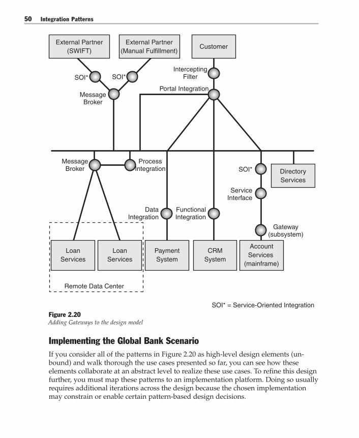
Integration Patterns50
External Partner(SWIFT)
SOI*
External Partner(Manual Fulfillment)
Customer
LoanServices
CRMSystem
PaymentSystem
SOI*
SOI*
ServiceInterface
Gateway(subsystem)
MessageBroker
SOI* = Service-Oriented Integration
Remote Data Center
MessageBroker
ProcessIntegration
FunctionalIntegration
DataIntegration
InterceptingFilter
Portal Integration
LoanServices
DirectoryServices
AccountServices
(mainframe)
Figure 2.20Adding Gateways to the design model
Implementing the Global Bank ScenarioIf you consider all of the patterns in Figure 2.20 as high-level design elements (un-bound) and walk thorough the use cases presented so far, you can see how theseelements collaborate at an abstract level to realize these use cases. To refine this designfurther, you must map these patterns to an implementation platform. Doing so usuallyrequires additional iterations across the design because the chosen implementationmay constrain or enable certain pattern-based design decisions.

Chapter 2: Using Patterns to Design the Baseline Architecture 51
For example, some of the implementation decisions will be constrained by decisionsthat the enterprise has already made. To understand these constraints, you need tounderstand the current technical architecture within your enterprise and make anintelligent initial allocation of functionality to server types. The members of theGlobal Bank team did this for their scenario and arrived at the model of their techni-cal architecture that is shown in Figure 2.21.
External Partner(SWIFT)
SOI*
External Partner(Manual Fulfillment)
Customer
LoanServices
CRMSystem
PaymentSystem
Model-View-Controller
SOI*
SOI*
ServiceInterface
Gateway(subsystem)
MessageBroker
SOI*
SOI* = Service-Oriented Integration
Remote Data Center
Half Synch/ Half Asynch
Gateway(object level)
Gateway(object level)
Gateway(object level)
SOI*
Pub/Sub
MessageBroker
ProcessIntegration
Pub/Sub
SOI*
ServiceInterface
InterceptingFilter
Portal Integration
LoanServices
DirectoryServices
AccountServices
(mainframe)
DataIntegration
Figure 2.21Initial Global Bank network diagram with server types

Integration Patterns52
To refine this model more, the members of the team needed to decide the platformor platforms to build their system on. Given the CTO’s constraints, some of theplatform infrastructure decisions were easy. For example, the account information ofrecord would reside on the mainframe. The mainframe is based on an IBM OS/390operating system. The acquired banks ran on systems based on WebSphere Java 2Enterprise Edition (J2EE). The rest of the systems would be based on the Microsoftplatform, as shown in Figure 2.22.
Customer
Model-View-Controller
SOI*
ServiceInterface
Gateway(subsystem)SOI*
SOI* = Service-Oriented Integration
Half Synch/ Half Asynch
Gateway(object level)
Gateway(object level)
Gateway(object level)
SOI*
SOI*
InterceptingFilter
Portal Integration
ASP.NET &.NET Framework
IBM OS390MicrosoftCRM?
SQL Server(Yukon)
Pub/Sub
MessageBroker
ProcessIntegration
Pub/Sub
Remote Data Center
BizTalk Server 2004
External Partner(SWIFT)
SOI*
External Partner(Manual Fulfillment)
SOI*
MessageBroker
BizTalk Server 2004
ServiceInterface
Host IntegrationServer 2004
.NET Framework
DataIntegration
IBM WebSphere J2EE
Active Directory
Figure 2.22Mapping the baseline architecture and patterns to technologies

Chapter 2: Using Patterns to Design the Baseline Architecture 53
Notice the mix of Microsoft and third-party technologies, as well as the questionmark associated with the Microsoft CRM system. The question mark indicates thatthe Global Bank team is still testing whether this system meets its requirements. Theteam will compare the performance test results with the actual operational require-ments obtained from the project team to see if this implementation meets its perfor-mance needs.
Later in this book, you will find these patterns described in detail, with matchingimplementation patterns to Microsoft technologies.
Note: The preview release of this guide does not document all the patterns that appear inFigure 2.22. For example, only some architecture and design patterns have matching imple-mentation patterns. However, some patterns have multiple implementation patterns, such asImplementing Service-Oriented Integration with ASP.NET and Implementing Service-OrientedIntegration with BizTalk Server 2004.
Next ChapterThis chapter showed how the Global Bank team applied patterns to design theirbaseline architecture. The description moved quickly over a wide range of patternsand technical challenges. The next chapter is the first of three pattern cluster chap-ters that describe these patterns in greater detail. Chapter 7, “A Language of Pat-terns,” uses a visual model to tie these patterns and their relationships together andto explain how the Global Bank team used this visual model to guide them throughtheir design choices.


3Integrating Layer
“Any problem in computer science can be solved with another layer of indirection.” —David Wheeler (chief programmer for the EDSAC project in the early 1950s)
As described in Chapter 1, connecting multiple systems requires an infrastructurethat moves data between the systems. However, you often want the solution to domore than just pass data around. You want to add an additional layer of functional-ity on top of the functional assets that reside inside the existing applications. Thislayer can automate complex business processes or provide unified access to informa-tion that is currently scattered across many systems.
How should such an integrating layer be designed, and what choices do you have?Unfortunately, there is no single right answer for all enterprise architectures. Thischapter discusses some of the key considerations to help you to understand thetradeoffs associated with the various alternatives and to find the most suitableapproach.
Level of AutomationA fully integrated enterprise seems to be any CIO’s idea of perfection. Complexinteractions between systems are orchestrated through precisely modeled businessprocess definitions. Any data format inconsistencies are resolved through the inte-gration layer. Relevant summary data is presented to executive dashboards with up-to-the-minute accuracy. Such visions are surely enticing, but should every enterpriseset out to build such a comprehensive and inherently complicated solution?
It is not likely that anyone would build such a solution because of the time andmoney it takes to build a complex enterprise integration solution. Therefore, decid-ing how far to go is an important step when planning an integration solution.Automation brings efficiency and can help eliminate inconsistencies in current

Integration Patterns56
business practices. However, complete automation can require an enormous upfronteffort that delays the tangible benefits to the business. A simpler solution might onlyachieve a portion of the business benefit, but it achieves that benefit much soonerand with much less risk. For example, displaying information from multiple systemsin a single screen that is divided into individual panels can increase productivity,and it does not require the system to resolve all the differences between existingsystems.
Level of AbstractionObject-oriented design principles teach the benefits of abstraction. Abstracting onesystem’s internals from other systems allows you to change one system withoutaffecting the other systems. This ability to limit the propagation of changes is a keyconsideration for integration solutions where connections can be plentiful andmaking changes to applications can be very difficult.
You achieve abstraction in a number of ways. For example, you can achieve abstrac-tion by passing self-contained documents between systems. Passing a documentdoes not instruct another system to perform a specific function, but it leaves thatchoice to the receiving system. Thus, if the receiving application processes thedocument in a different way, the originating system is not affected.
Maintaining StateMost integration solutions aim to streamline business processes such as placing anorder or making a payment. These processes rely on the coordinated completion of aseries of steps. When an order arrives, the order has to be validated, the inventoryhas to be checked, the sales tax has to be computed, and an invoice has to be gener-ated. This type of integration requires some mechanism to track the current state ofan order. For example, the mechanism might indicate whether the order has beenvalidated yet and which step should be completed next. This state mechanism canbe implemented in three ways:● Manually. State can reside in the user’s head or in a manual on the user’s desk.
Based on the information gathered, a user can decide which step should beperformed next. This approach is less efficient and less reliable than more auto-mated solutions, but it is also very flexible and easy to implement.
● Inside existing applications. The state can be kept inside existing applications.For example, after the inventory application has verified the number of items onhand, it can be programmed to send a message to the financial system to com-pute the sales tax. The financial system in turn might send a message to thefulfillment system to ship the goods. This approach is more efficient but also tiesthe applications more closely to each other.

Chapter 3: Integrating Layer 57
● In an integration layer. You can insert a new integration layer to orchestrate theactivities across multiple applications and to keep track of state. Such a layer islikely to require additional effort, but it manages all interactions from a centralpoint without applications requiring information about each other.
CouplingLoose coupling has become the standard of distributed applications. Loose couplingmakes integrated systems less dependent on each other and allows them to evolveindependently. However, loose coupling is not a panacea. Loosely coupled systemscan often be difficult to understand and debug.
Semantic DissonanceOne of the key difficulties in building integration solutions is the notion ofsemantic dissonance. This term describes a situation where data that appears to be thesame may not necessarily mean the same thing. For example, one system might treata monetary figure for annual revenues as if it includes sales tax, while anothersystem treats the monetary figure as if it does not include any taxes. Likewise, onesystem might define the Western Region, in the context of revenue breakdown, toinclude the state of Colorado. Meanwhile, another system may define Colorado aspart of the Central Region. These types of semantic dissonance can be very difficultto detect and reconcile. Some rather elegant types of integration rely on the completeresolution of semantic dissonance, which might not be feasible in real-life situations.Other simpler forms of integration, such as Portal Integration, can accommodateambiguity, but they do it at the expense of precision. For an in-depth discussion ofdata modeling and the perils of semantic dissonance, see Data and Reality, by WilliamKent [Kent00].
Choosing an Integration Layer TypeBased on these considerations, this guide identifies three approaches towardsintegrating layers. Each approach is presented as a pattern (see Figure 3.1):● Entity Aggregation● Process Integration● Portal Integration

Integration Patterns58
Entity Aggregation Process Integration Portal Integration
Figure 3.1Three integration approaches
The following paragraphs briefly describe each approach to integration, in orderfrom least to most complex.
Portal IntegrationPortal Integration connects systems to provide a unified view to a user. Portal Integra-tion can dramatically increase productivity because users no longer have to accessmultiple applications independently. Instead, they receive a comprehensive viewacross all systems in a visually consistent format that is illustrated in Figure 3.2.More sophisticated versions of Portal Integration also allow the user to make updatesto individual systems or even across multiple systems.
System 1 System 2 System 3 System 4
Portal Integration
Figure 3.2Portal Integration provides a unified view across systems

Chapter 3: Integrating Layer 59
Portal Integration is often easier to implement than other, more automated alterna-tives. The disadvantage of the simplicity is that much of the business process andmany of the rules still reside in a user’s head as opposed to in a system. Neverthe-less, Portal Integration is often a good first step towards integration.
Entity AggregationThe main limitation of Portal Integration is that it aggregates information only forend users but not for applications. Entity Aggregation addresses this shortcoming byproviding a unified data view to applications, as illustrated in Figure 3.3.
Applications and Services
System 1 System 2 System 3 System 4
Entity Aggregation
Figure 3.3Entity Aggregation provides unified data access across systems
Entity Aggregation provides a logical representation of unified data entities acrossmultiple data stores. Applications can interact with this representation as if it were asingle data source. Thus, Entity Aggregation greatly simplifies the development ofapplications that need to access data across multiple data stores. The tradeoff for thisincreased integration is that the integration layer must now resolve any instances ofsemantic dissonance between the individual systems. Resolving such semanticdissonance and creating a unified data layer can be a major undertaking.
Process IntegrationProcess Integration focuses on the orchestration of interactions between multiplesystems, as illustrated in Figure 3.4. As mentioned earlier, automated businessprocesses such as straight-through processing often drive integration initiatives. It isoften advisable to model these processes outside of the applications to avoid cou-pling the applications to each other. You can achieve this modeling by adding aProcess Integration layer that manages the interaction across applications. This layertracks the state of each business process instance and also enables centralized

Integration Patterns60
reporting. For example, this layer enables the Business Activity Monitoring (BAM)feature of Microsoft BizTalk® Server.
System 1 System 2 System 3 System 4
Process Integration
Figure 3.4Process Integration orchestrates activities across systems
The three integration layer types are not mutually exclusive. An integration solutionmight use Portal Integration for some portions of the solution and Process Integrationfor others. Management reporting functions may be accomplished by using EntityAggregation. All the approaches may be used in parallel.
Integrating Layer PatternsThe following table summarizes the three patterns just discussed and shows thecorresponding implementation patterns.
Table 3.1: Integrating Layer Patterns
Pattern Problem Associated implementations
Entity Aggregation How can enterprise data that isredundantly distributed acrossmultiple repositories be effectivelymaintained by applications?
Process Integration How do you coordinate the execution Implementing Processof a long-running business function Integration with BizTalkthat spans multiple disparate Server 2004applications?
Portal Integration How can users efficiently performtasks that require access toinformation that resides indisparate systems?
Chapter 3: Integrating Layer 61
Entity Aggregation
ContextEnterprise-level data is distributed across multiple repositories in an inconsistentfashion. Existing applications need to have a single consistent representation of keyentities which are logical groups of related data elements such as Customer, Product,Order, or Account. Moving data between these repositories may not be a viableoption.
ProblemHow can enterprise data that is redundantly distributed across multiple repositoriesbe effectively maintained by applications?
ForcesThe following forces have to be considered in this context:● There may be multiple systems of record for the same entity. Business rules and
processes could dictate the manner in which the system of record is determinedfor a given entity. For example, an employee entity is usually defined in humanresource management system (HRMS) applications, in payroll applications, andin benefits applications, as well as in other systems. Each system defines its ownview of an employee. However, if you are building an employee self-serviceportal, you need to have a complete view of what constitutes an employee andnot just the bits and pieces.
● Often, semantic dissonance exists between the data values represented within thesame entity across repositories. The same data element may not represent thesame information in multiple repositories. For example, the data elementNumberOfDaysRemaining for a project task might include all days includingholidays in one repository, but it might include only workdays in anotherrepository.
● Even when the data elements are semantically consistent, the information theyrepresent might vary across parallel instances of the data element. In such cases,it may be difficult to determine which instance of the data element is accurate.For example, in a financial institution where there are dedicated repositories forvarious customer communication channels, the Available Balance entity in onerepository may not be the same as the Available Balance in another repository.For example, the Available Balance in the ATM database may not be the same asthe Available Balance in the repository serving the online banking channel.

Integration Patterns62
● Invalid data might have crept in through other entry points into the repositories.All the entry points may not enforce all the business and data validation rules ina consistent fashion. This is typical of mainframe systems where the validationlogic enforced in the screens may be outdated and therefore not enforced in theenterprise’s newer applications.
● Referential integrity of data across multiple repositories may have been violated.This happens due to absent or malfunctioning data synchronization processes. Ina manufacturing environment, it is critical that the product data management(PDM) system always be concurrent with the order management system. Ordersentered in the order management system that have an invalid reference to aproduct can violate the referential integrity of the product data across the respec-tive repositories.
● Applications may need logical subsets of the data elements that may not beavailable in a single repository. Therefore, business logic may have to be appliedto properly group the data elements into the logical subset. For example, abanking customer maintains different kinds of information across various reposi-tories. Personal information is stored in the customer information file repository;account balance is stored in a financial application repository; and loan informa-tion is stored in the mortgage lending repository. When the customer accesses theonline banking site, the nature of the customer’s request determines the subset ofthe information to be presented. An address change request needs data from thecustomer information file repository, but an inquiry on the outstanding balancefor all accounts and loans requires specific data from all three repositories.
● Data synchronization processes may already exist between repositories thatpermit one repository to act as a front end to the other. In these cases, the syn-chronization mechanism is better left untouched. This is typical where databasereplication is used across two separate database instances that use the sameunderlying technology.
SolutionIntroduce an Entity Aggregation layer that provides a logical representation of theentities at an enterprise level with physical connections that support the access andthat update to their respective instances in back-end repositories.
This representation is analogous to the Portal Integration pattern, which presents tothe end user a unified view of information that is retrieved from multiple applica-tions. Similar to the portal layer that provides this view for the application frontends, the Entity Aggregation layer provides a similar view across the data in the back-end repositories as shown in Figure 3.5.

Chapter 3: Integrating Layer 63
Repository 1 Repository 2
Entity AggregationLayer
Application
Repository 3
Figure 3.5Entity Aggregation
Establishing Entity Aggregation involves a two-step process:1. Defining the enterprise-wide representation that provides a consistent unified
representation of the entity.2. Implementing a physical bidirectional connection between this representation
and its respective instances in the back-end repositories.
The following example explains this process in more detail.

Integration Patterns64
U.S. Repository
Area CodeExchangeNumber
Phone Number
EMEA Repository
Back-End Repositories
Front-End Applications
Country CodeCity CodeExchangeNumber
Phone Number
U.S. Application EMEA Application
U.S. Enterprise EMEA Enterprise
Figure 3.6Environment without Entity Aggregation
Figure 3.6 shows two applications that access their respective back-end repositoriesfor information about the Phone Number entity within two different enterprises:U.S. Enterprise and the Europe, Middle East, and Asia (EMEA) Enterprise. Bothapplications maintain the information about the phone number within their respec-tive repositories.
Each application follows the respective domestic convention for representing phonenumbers in its back-end repository. The U.S. representation of the entity includes thearea codes, the exchanges, and the numbers. The EMEA representation, on the otherhand, represents the same information using the country code, the city code, theexchange, and the number.
As part of a merger and acquisition exercise, these enterprises merge to form a newlogical enterprise. Both applications have to access the information in both reposito-ries. Therefore, the phone number now has to be represented at an enterprise-widelevel that includes both the U.S. and the EMEA business units.

Chapter 3: Integrating Layer 65
Back-End Repositories
EntityAggregation
Layer
Front-End Applications
U.S. Repository
Area CodeExchangeNumber
Phone Number
Country CodeArea CodeExchangeNumber
Phone Number
EMEA Repository
Country CodeCity CodeExchangeNumber
Phone Number
U.S. Application EMEA Application
U.S. Enterprise EMEA Enterprise
Figure 3.7Environment with Entity Aggregation
Figure 3.7 shows the manner in which Entity Aggregation can facilitate the seamlessrepresentation of the Phone Number entity across both repositories.
The first step in establishing this layer involves defining the enterprise-wide repre-sentation of the Phone Number entity.
The Phone Number entity within the Entity Aggregation layer includes attributes thatare unique to each enterprise. The Phone Number entity also includes attributes thatare common across both enterprises. Thus, Country Code is included because it is anattribute unique to the EMEA enterprise. Similarly, because Exchange and Numberare common attributes across both repository instances, they are also included. Eventhough Area Code and City Code are unique to each enterprise, their basic represen-tation and purpose is identical. Therefore, the Entity Aggregation layer representation

Integration Patterns66
chooses to include the Area Code while using this field to store the City Codeinformation from the EMEA repository.
The next step involves building the physical connections between the Entity Aggre-gation layer and the back-end U.S. and EMEA repositories. The technology drivingthese connections depends on the repository being accessed.
ApproachThere are two architectural approaches to implementing Entity Aggregation:● Straight-through processing● Replication
Depending on the architectural characteristics of the entity instances to be inte-grated, a combination of these approaches may be required.
Straight-Through Processing
A straight-through processing approach fetches information from the respectiveback-end repositories in real time and correlates the information into a single unifiedview. This implies that the Entity Aggregation layer has real-time connectivity to therepositories and should be able to associate the disparate instances of the entity.
Replication
The replication of entities for use by the Entity Aggregation layer is required whenthe following conditions are true:● Real-time connectivity to the repositories is absent.● Complicated joins across multiple instances of the same entity across various
repositories is required to provide a consistent representation.● High performance is vital to the solution.
This approach requires a separate physical repository within the Entity Aggregationlayer that stores data conforming to the enterprise-wide representation of the entity.The data in each back-end repository is replicated into the Entity Aggregation reposi-tory. This replication requires the implementation of supporting processes to enforcethe business rules that validate the data being replicated. Replication should beperformed both ways between the back-end repositories and the Entity Aggregationrepositories.
In many respects, this approach offers capabilities very similar to those supported by adata warehouse. Data warehouses originally were built with the intent of summariz-ing transactional data that could be used for business intelligence and trends analysis.In many large enterprises today, data warehouses have transformed into yet anotherrepository within the enterprise. They do not always serve as the enterprise-wideunified representation of the data. However, such data warehouses have a good

Chapter 3: Integrating Layer 67
baseline definition for enterprise-level entities, and the enterprise-wide representationof an entity can be built on top of this definition.
Design ConsiderationsEffective design of an Entity Aggregation layer requires several issues to be given dueconsideration. These issues may be broadly classified as follows:● Data representation. Data representation includes entity representation and schema
reconciliation. Entity representation is the definition of the enterprise-wide repre-sentation of the entity with its attributes and key relationships to other entities.Schema reconciliation involves reconciling the varied definitions of the underly-ing schema across repositories. In addition to the data representation beingdefined, the format in which the representation is stored must be established aswell.
● Data identification. Introduction of a new layer of data representation requiresthe establishment of an appropriate mechanism that uniquely identifies eachentity across all repositories, including the Entity Aggregation layer itself. Anentity reference is one such mechanism.
● Data operation. Data operation includes the manner in which transactionaloperations are performed on the data. This includes Create, Read, Update, andDelete (CRUD) actions, and it includes any compensatory measures thereof. Formore information about this consideration, see “Inquiry vs. Update” later in thispattern.
● Data governance. Data governance involves establishing ownership of ongo-ing maintenance and establishing change management processes to direct theongoing maintenance of entities and their data elements. These processes alsohelp refine the integration requirements by rationalizing the number of datarepositories, if necessary.
Each of these issues is outlined in the following sections.
Entity Representation
There are several approaches that could be adopted to defining the enterprise-widerepresentation of the entity.
Entity representations may have to be custom developed to address the specificneeds of the enterprise as whole. This may be the only viable option under thefollowing circumstances:● Existing representations within the enterprise represent only a small portion of
the enterprise-wide representation of the entity and are not readily extensible toaccommodate the needs of the enterprise.
● Characteristics that are unique to the enterprise cannot be properly reflectedwithin any external representations of the entity.

Integration Patterns68
However, custom representations are not always a financially viable option becausethey require a regeneration of the existing entities and their relationships.
Instead, a representation that is foreign to all the applications within the enterprisemay be a viable approach as long as it still conforms to the core business processes.You could also use current representations that are specific to certain industries forthis purpose. In other words, embracing an external representation does not neces-sarily entail the additional expense of procuring an application.
In other cases, you could choose the representation supported by one of theexisting applications within the enterprise. ERP and CRM applications that supportand drive the business processes for the enterprise are prime candidates for thisapproach.
While Entity Aggregation is all about having a single view of entities across theenterprise, entity representations within this layer might have to be adjusted torepresent the nuances of individual business units. This is especially true for largeinternational conglomerates that have been forced into being a logical enterprisethrough acquisitions and mergers of other enterprises that operate as autonomousbusiness units.
Reaching a consensus on the representation within any one of these units can be achallenge. Therefore, reaching a similar consensus across all of these units can be anambitious goal, if not an impossible one. In these cases, multiple representations (onefor each operating unit) might be a more realistic and practical approach.
Schema Reconciliation
Even if the enterprise reaches consensus on the entity representation, the representa-tion within each instance of the entity may still vary across different repositories.Different repositories can hold different schemas for the same entity. The EntityAggregation layer must harmonize the subtle differences between these schemas inthe following ways:● Entity Aggregation must account for the representation of all entities held within
the different repositories.● Entity Aggregation must define a unified schema for all entities which represents
a logical consolidation of all the views.● Entity Aggregation must effect transformations between each repository’s schema
and the unified schema.
Note: Sometimes, the term canonical schema is used instead of unified view. This pattern usesthe latter term, because canonical schema implies that all the representations share the sameschema, which is not always necessary.

Chapter 3: Integrating Layer 69
Figure 3.8 shows an example of customer information that is represented in morethan one repository. Although the contact repository defines the contact informationfor a customer, the financial repository defines the credit card details for the cus-tomer. The Entity Aggregation layer defines a unified schema that contains all theattributes required for representing the customer entity. The Entity Aggregation layeralso defines the mapping between the unified schema and those schemas held by theindividual repositories.
Customer
Contact Repository
Back-EndRepositories
Entity AggregationLayer
Customer IDLast NameFirst NameAddressSocSecIDEmailPhoneNum
Customer
Financial Repository
Financial Mapping
Contact Mapping
Customer IDCard TypeCard NumExp Date
Customer
Customer IDLast NameFirst NameAddressSocSecIDEmailPhoneNumCard TypeCard NumExp Date
Figure 3.8Schema reconciliation

Integration Patterns70
References
Entity reference is the information required to uniquely identify an entity. Repositoriesthat store instances of a given entity tend to maintain their own unique identifiers fortheir respective instances to ensure they have full control over internal data consis-tency. The Entity Aggregation layer should account for this and should be able to mapreferences that point to a single instance. Apart from references that are held by otherrepositories, the Entity Aggregation layer might create its own reference for an entityinstance. The idea here is that the Entity Aggregation layer maintains its own referenceto an entity instance and maps this reference to the individual repository’s reference.This reduces the coupling between the Entity Aggregation layer and individual reposi-tories because new repositories can be introduced without affecting the Entity Aggrega-tion layer’s unified view.
Master Reference
Entity Aggregation layer uniquely identifies an entity instance by using a referenceknown as a master reference. A master reference could be:● A reference held by one of the repositories. For example, you can designate the
reference held by a CRM repository as the master reference for a customer entity.● A new reference that the Entity Aggregation layer creates for the entity instance
and maps to other references held by different repositories.
Inquiry vs. Update
The technological solutions available today are more robust for inquiring than theyare for updating data in the back-end repositories. Updating has the inherent chal-lenges of maintaining the synchrony of data across repositories.
Note: In the context of this pattern, deleting an entity is considered to be a form of update.
An update request usually contains two elements: a reference that uniquely identi-fies the instance and an update payload that contains information about the updatedattributes and their respective values.
The Entity Aggregation layer uses entity references across all the repositories toperform the inquiries and updates. Although the Entity Aggregation layer maintainsthe entity reference, the references that are unique to each repository have to bedetermined before the update is made to the back-end repositories. For more infor-mation, see “References.”
Compensation
The process of performing a compensating action can be manual or automatic.Business process owners have a strong influence on the manner in which compen-sating actions should be implemented.

Chapter 3: Integrating Layer 71
If one of the systems fails to handle the update request, the Entity Aggregation layershould be able to handle this business exception by using one of the followingapproaches:● Request a rollback on all the other updates that have already been made.● Run a compensating transaction to reverse the effects of the successful updates
that were already completed.
Ownership
Although the Entity Aggregation layer represents the unified view of an entity, it iscertainly possible to store different fragments of an entity in different systems.Therefore, the system of record is not the same for all fragments.
For example, employee information could be distributed across the payroll andbenefits repositories. It is also possible that some information may be owned bymultiple systems. For example, attributes such as LastName and FirstName areprobably represented in more than one system. In this case, the Entity Aggregationlayer should designate a system as an authoritative source for attributes that arerepresented in more than one system.
This has several implications for the behavior that occurs during inquiries andupdates. Attributes will always be fetched from the authoritative source. If the sameattribute is represented by another system, those values will be ignored by the EntityAggregation layer. Updates, on the other hand, have different semantics. When theEntity Aggregation layer receives an update request for an entity, the updates shouldbe propagated to all the constituent systems of record.
Change Management
Processes have to be put in place to coordinate changes across all the repositoriesand the Entity Aggregation layer. In addition to ensuring active participation from thedifferent business process owners and information technology (IT) representativesfor each repository, a key step in this process is to ensure that the integrity of theenterprise-wide representation of the entity is not compromised.
Three types of changes to the underlying repositories can directly and significantlyaffect the Entity Aggregation layer:● Configuration. The repository configuration could undergo changes. This would
include redeployment of the repository to a new physical location or to a differ-ent server. Configuration parameters such as the scheduled downtime for mainte-nance could affect connectivity to the Entity Aggregation layer as well. In an idealenvironment, only the Entity Aggregation layer is directly affected by this changebecause connections between repositories usually do not exist. However, theother repositories could be indirectly affected by these changes through theirconnectivity to the Entity Aggregation layer.

Integration Patterns72
● Data model. The data model could undergo changes within the repository. Theenterprise-wide representation of entities supported by the Entity Aggregationlayer is significantly affected by these changes. Other repositories that storeinformation in the same domain are affected also.
● Data values. Changes to transactional data in a repository have the least impact,if any, on the Entity Aggregation layer and on other repositories. However,changes to reference data that spans repositories or to reference data that is usedby the Entity Aggregation layer have a significant impact.
ExampleFigure 3.9 shows a scenario where the Stock Trade entity is partitioned acrosssystems based on geographical constraints. Applications that analyze the trends in agiven industry require a complete view of the trades across geographical boundariesand systems.
The Entity Aggregation layer consolidates the view across geographical boundariesso that the partitioning of data across the repositories is transparent to the applica-tions that perform trends analysis.
U.S. Trades
Global Trades
Entity Aggregation Layer
Stock TrendsAnalysis Application
EMEA Trades
Figure 3.9Stock trades scenario
Chapter 3: Integrating Layer 73
Resulting ContextEntity Aggregation has the following benefits and liabilities:
Benefits● Consensus. Entity Aggregation forces consensus across business and functional
units on the manner in which entities are represented at an enterprise-level.● Single view. Entity Aggregation enables a single view of key business entities such
as Customer, Account, Product, and (in the case of healthcare) Patient.● Improved access to information. An enterprise-level view of key business
entities enables applications to have immediate access to the information perti-nent to these entities. Access to information is not constrained by the repositoriesthat house them.
● Reduced semantic dissonance. Entity Aggregation eliminates semantic dissonanceacross existing applications that work on the same data elements from multiplerepositories.
● Central location. Entity Aggregation supports a central location for validatingdata that is populated into the repositories.
● Reduced change impact. Entity Aggregation reduces the potential impact ofchanges to the back-end repositories. Depending on the nature of the changesbeing made, the Entity Aggregation layer can continue to serve the needs of theapplications while these changes are in progress.
Liabilities● Additional layer. Entity Aggregation introduces an additional architectural layer
that could adversely affect end-to-end performance of the solution.● Consensus. Entity Aggregation requires consensus across business units on the
definition of the enterprise-wide representation of entities.● Reengineering applications. Existing applications that are tightly coupled to a
given set of repositories would have to be reengineered to accommodate the newarchitectural layer. Additionally, it is not always possible to reengineer someapplications — especially packaged solutions.
Integration Patterns74
Testing ConsiderationsThe following testing considerations apply when adding an Entity Aggregation layer:● Depending on the degree to which the Entity Aggregation layer is adopted, all
valid combinations of applications and their back-end repositories would have tobe regression tested.
● Existing test cases may have to be revised to reflect the business rules beingexercised in the Entity Aggregation layer.
● Test data available within a given repository must be repurposed to accommo-date the enterprise-wide representation of entities in the Entity Aggregation layer.
● Simultaneous connectivity from the Entity Aggregation layer to all the back-endrepositories has to be tested. In the absence of Entity Aggregation, connectivitywould have been a requirement only between the various application-repository pairs.
Security ConsiderationsThe Entity Aggregation layer is effective at providing access to information that ispertinent to business entities at an enterprise level. However, applications might beable to obtain access to repositories that may not have been available prior to theintroduction of the Entity Aggregation layer. Even though applications might stilloperate on the same data elements, they might access new repositories through theEntity Aggregation layer. Access privileges for various roles within these applicationshave to be managed at the Entity Aggregation layer.
Operational ConsiderationsThere are two separate operational aspects to the Entity Aggregation layer:● The Entity Aggregation layer has to be operated and monitored as a repository
that houses the enterprise-wide representation of entities. Less maintenance ofthe underlying data in the Entity Aggregation layer is required for the straight-through processing solution than for the replication solution. In the replicationsolution, the operational aspects that apply to the data in the repositories alsoapply to the Entity Aggregation layer. In either case, similar operational aspectsapply if the Entity Aggregation layer maintains the entity references that areexternal to all the repositories.
● Network connectivity between the applications and the Entity Aggregation layerand network connectivity between the Entity Aggregation layer and the reposito-ries are critical components of the overall solution. The straight-through process-ing solution, in particular, requires concurrent connectivity to all the repositories.

Chapter 3: Integrating Layer 75
Known UsesEnterprise Information Integration is another industry term that is used to identifythe enterprise-wide representation of a logical data model that houses the keybusiness entities that have bidirectional physical connections to the back-end reposi-tories where data is stored.
Some companies provide a logical metadata modeling approach that allows enter-prises to reuse models and data for real-time aggregation and caching with updatesynchronization. All these companies initially provided query-only capability, butthey are slowly beginning to support bidirectional transfer of data between theEntity Aggregation layer and the back-end repositories.
Related PatternsGiven that the Entity Aggregation layer provides a view of data that is distributedacross repositories, Data Integration is closely related to this pattern.

Integration Patterns76
Process Integration
ContextYou have multiple disparate systems, and each of those systems is part of an overallbusiness function. For example, a business function such as processing an incomingorder may require the participation of the customer management system, the inven-tory system, the shipping system, and one or more financial systems. The businesscould operate more efficiently if the systems could be integrated so that the businessfunction could be completed automatically.
ProblemHow do you coordinate the execution of a long-running business function that spansmultiple disparate applications?
ForcesTo solve this problem, you have to balance the following considerations and forces:● To implement the overall business function, you could have one system directly
call the system that performs the next step, as defined in the business function.However, this approach encodes the sequence of interactions into the individualsystems. Creating this dependency in each system makes changing the sequencemore error-prone and also limits your ability to reuse systems in multiplecontexts.
● The change and maintenance cycle of a complex business function is likely to bedifferent from the change cycle of the individual business functions that resideinside the applications. For example, financial functions such as computing salestax or posting revenues are typically subject to infrequent, but mandatory, legalor regulatory changes. In contrast, the overall execution of a business functionmight be changed much more frequently based on business and marketingstrategies.
● Complex business functions can often take days or weeks to complete.However, most functions that are available in existing applications are synchro-nous; that is, the caller has to wait while the application performs the requestedfunction. This type of synchronous interaction is not well-suited to long-runningbusiness functions because one application could spend a significant amount oftime waiting for another application to complete the requested function.
● A longer time span of execution increases the likelihood that an application mightfail during the execution of the business function. If one application fails, por-tions of the overall function may have to be reverted so that all systems can bereturned to a consistent state.
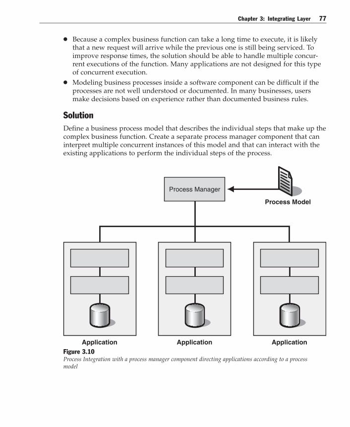
Chapter 3: Integrating Layer 77
● Because a complex business function can take a long time to execute, it is likelythat a new request will arrive while the previous one is still being serviced. Toimprove response times, the solution should be able to handle multiple concur-rent executions of the function. Many applications are not designed for this typeof concurrent execution.
● Modeling business processes inside a software component can be difficult if theprocesses are not well understood or documented. In many businesses, usersmake decisions based on experience rather than documented business rules.
SolutionDefine a business process model that describes the individual steps that make up thecomplex business function. Create a separate process manager component that caninterpret multiple concurrent instances of this model and that can interact with theexisting applications to perform the individual steps of the process.
Process Manager
Process Model
Application Application ApplicationFigure 3.10Process Integration with a process manager component directing applications according to a processmodel

Integration Patterns78
For each incoming request for the business function, the process manager creates anew process instance based on the process model. Each instance maintains thecurrent state of the process plus any additional information that is needed for thebusiness process to continue. Creating individual process instances allows theprocess manager to execute many business functions in parallel.
After one application completes its business function, the process manager deter-mines which function to execute next based on the state of the process instance.Therefore, each participating application can operate individually without anyknowledge of the sequence of steps defined in the process model.
The process manager maintains this state even if a specific application is temporarilyunavailable. As a result, the overall execution of the business function is not stoppedif a specific application is temporarily unavailable. Instead, the business functioncan continue after the application is back online.
The process manager interacts with the individual applications by way of DataIntegration, Functional Integration, or Presentation Integration, depending on the natureof the interaction and the architecture of the application. Therefore, Process Integra-tion resembles a composite application built on top of existing business functions thatreside in existing applications.
Process Integration provides a clean separation between the definition of the processin the process model, the execution of the process in the process manager, and theimplementation of the individual functions in the applications. This separationallows the application functions to be reused in many differentprocesses.
The separation of process model and process manager also allows the processmanager to be domain independent because it only has to interpret the basic con-structs that form a process model. These constructs manage the parallel execution ofmultiple steps, and they typically comprise sequences, decision points, forks, andjoins. Using these constructs, enterprises can create a model at the business levelwithout having to understand the internals of the process manager or the individualapplications.
Process Integration involves collaboration between the components that are describedin Table 3.2.
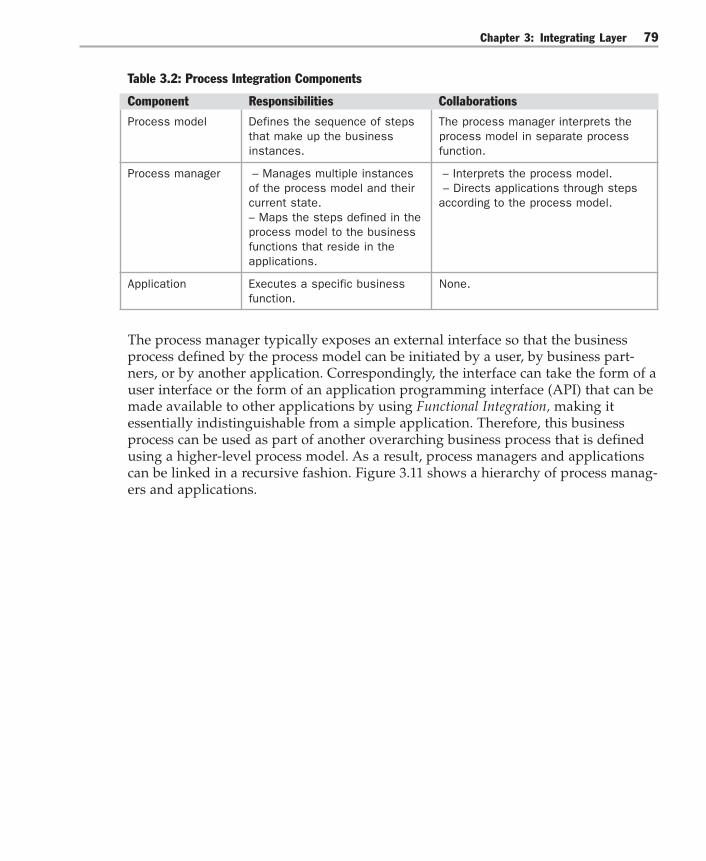
Chapter 3: Integrating Layer 79
Table 3.2: Process Integration Components
Component Responsibilities Collaborations
Process model Defines the sequence of steps The process manager interprets thethat make up the business process model in separate processinstances. function.
Process manager – Manages multiple instances – Interprets the process model.of the process model and their – Directs applications through stepscurrent state. according to the process model.– Maps the steps defined in theprocess model to the businessfunctions that reside in theapplications.
Application Executes a specific business None.function.
The process manager typically exposes an external interface so that the businessprocess defined by the process model can be initiated by a user, by business part-ners, or by another application. Correspondingly, the interface can take the form of auser interface or the form of an application programming interface (API) that can bemade available to other applications by using Functional Integration, making itessentially indistinguishable from a simple application. Therefore, this businessprocess can be used as part of another overarching business process that is definedusing a higher-level process model. As a result, process managers and applicationscan be linked in a recursive fashion. Figure 3.11 shows a hierarchy of process manag-ers and applications.
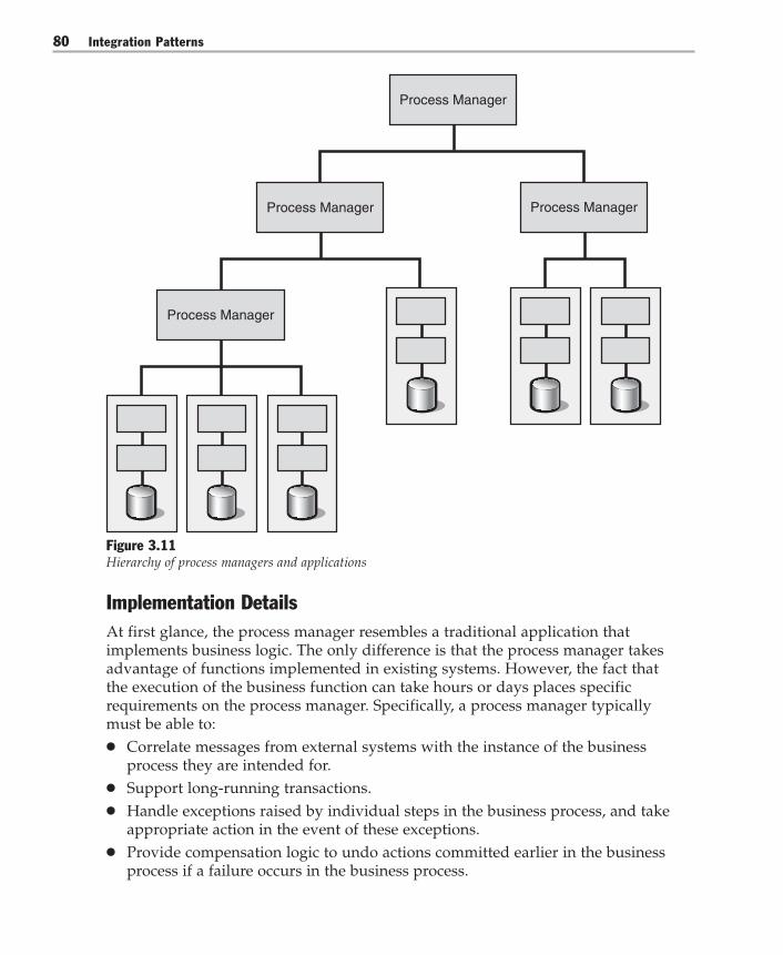
Integration Patterns80
Process Manager
Process Manager
Process Manager
Process Manager
Figure 3.11Hierarchy of process managers and applications
Implementation DetailsAt first glance, the process manager resembles a traditional application thatimplements business logic. The only difference is that the process manager takesadvantage of functions implemented in existing systems. However, the fact thatthe execution of the business function can take hours or days places specificrequirements on the process manager. Specifically, a process manager typicallymust be able to:● Correlate messages from external systems with the instance of the business
process they are intended for.● Support long-running transactions.● Handle exceptions raised by individual steps in the business process, and take
appropriate action in the event of these exceptions.● Provide compensation logic to undo actions committed earlier in the business
process if a failure occurs in the business process.

Chapter 3: Integrating Layer 81
Correlating Messages and Process Instances
Orchestration of processes involves messages sent to external systems and receivedfrom external systems. These external systems implement the actions that make upthe business process. At any time, there are likely to be many instances of thebusiness process running at once, and any message that is received must becorrelated with the correct instance of the business process that it was intended for.
Transactions
Transactions provide encapsulation of individual atomic actions. A transaction isan action or a series of actions that transform a system from one consistent stateto another. When dealing with long-running business functions, it is useful todistinguish between two kinds of transactions: atomic transactions and long-running transactions. When you use Process Integration, your design must supportboth kinds of transactions.
Atomic transactions are the same kind of transactions as those found in databases.They adhere to a set of properties, commonly called the Atomicity, Consistency,Isolation, and Durability (ACID) properties. This type of transaction requirestransactional resources, such as a database update or the sending of a message, thatpermit you to automatically roll back changes if the transaction is stopped. Atomictransactions are suited only for short-running portions of the overall process.
Long-running transactions are used when one or more of the following conditionsare true:● The transactions must occur over an extended time period, and the transaction
cannot be supported by atomic transactions.● The actions involved in the transaction are not themselves transactional, but you
want to group these actions into more granular atomic units of work that canexist across time, organizations, and applications.
● Other transactions are grouped within a transaction. Both atomic and long-running transactions may be grouped in a long-running transaction, but othertransactions cannot be grouped in an atomic transaction.
For long-running transactions, you must allow the user to stop the process mid-stream. When the process stops, the system will persist data regarding the com-pleted actions and the intermediate states. After the process restarts, the applicationwill reload this intermediate state to allow the process to continue from the pointwhere it stopped.

Integration Patterns82
Handling Exceptions and Compensating Transactions
When external applications are invoked to implement a specific action, a variety oferrors can occur. These errors cause error codes to be sent in messages that arereturned by the external systems, and these errors cause exceptions to be thrown.
Status code errors can be handled by conditional logic inside the process model. Thisapproach is natural, but can lead to an unwieldy control flow if all possible errorconditions have to be covered. Errors in the form of exceptions can be handled byexception handlers attached to the scope in which the exception occurred. This scopecan be the entire process model, or it can be a specific subsection. If an exceptionoccurs within this scope, the exception handler is automatically invoked without theprocess designer having to explicitly model each individual error condition.
Some of these errors require the application to revert the transaction state to the statebefore the long-running transaction started. When these errors occur, the applicationissues a compensating transaction.
ExampleProcess Integration is commonly used to streamline the execution of a sequence oftasks. One popular application in the financial industry is the notion of straight-through processing (STP). STP describes the automated end-to-end processing oftransactions such as trades from inception to settlement.
As described in the solution section, Process Integration can also be used to provide anaggregate service to other applications. For example, consider a service that makesconcurrent updates to multiple data sources as defined in Entity Aggregation. Theimplementation of such a service requires Process Integration internally to managetransactional integrity, partial failure situations, and compensation actions.
Process Integration is such a common need that standards committees and workinggroups are defining standard languages to describe process models. Examples ofsuch languages are:● Business Process Modeling Language (BPML)● Business Process Execution Language (BPEL)● Web Services Choreography Interface (WSCI)
Resulting ContextProcess Integration results in the following benefits and liabilities:

Chapter 3: Integrating Layer 83
Benefits● Maintainability. Creating a separate process integration layer allows users to
define and maintain the business process independent from the implementationof the individual functions. This increases maintainability and reduces the skillset requirements for the personnel who maintain the process definition.
● Reusability. Because the existing applications are not dependent on the processmanagement layer, the functions inside these applications can be reused inmultiple process definitions.
● Flexibility. The process manager can support a variety of configurations thatwould be difficult to implement in many traditional programming models. Forexample, parallel execution of multiple tasks, synchronization points, timeouts,and escalations are all configurations that would be difficult to implement in atraditional programming model. Supporting a variety of configurations gives theprocess manager the flexibility to adapt to many different business requirements.
● Reporting capability. Because the process instances are maintained centrally, itbecomes feasible to extract statistical information that spans multiple processsteps and process instances. Such reports can provide answers to questions suchas “How long does it take on average to fulfill an order?” or “How many ordersare on hold due to insufficient inventory?” This type of reporting can be instru-mental in making informed business decisions.
Liabilities● Potential bottleneck. Managing a large number of process instances in a central
process manager component can present a run-time bottleneck. However, in mostcases, the parallel execution of multiple process manager instances can alleviatethis threat while maintaining the benefit of central configurability.
● Temptation to overuse. This liability is the flip side of the flexibility inherent inProcess Integration solutions. Because Process Integration can be used to solvenearly any integration problem, some people take this as an indication that eachand every integration problem should be solved using Process Integration. This isnot true. Using Process Integration frivolously can lead to overarchitected andsometimes inefficient solutions — for example, in cases where a Message Brokerwould be perfectly appropriate to address the requirements.
● Complexity. A generic process manager can be difficult to build because it has todeal with concurrency, checkpoints, and recoverability. For these reasons, acommercial process manager should be used whenever possible. If a commercialcomponent is not available, the cost of building the process manager should becarefully weighed against the cost of making changes to the process model.
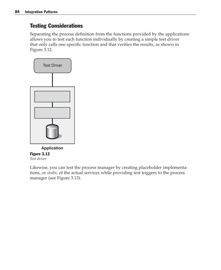
Integration Patterns84
Testing ConsiderationsSeparating the process definition from the functions provided by the applicationsallows you to test each function individually by creating a simple test driverthat only calls one specific function and that verifies the results, as shown inFigure 3.12.
Application
Test Driver
Figure 3.12Test driver
Likewise, you can test the process manager by creating placeholder implementa-tions, or stubs, of the actual services while providing test triggers to the processmanager (see Figure 3.13).

Chapter 3: Integrating Layer 85
Process Manager
Test Stub Test Stub Test Stub
Figure 3.13Using stubs to test the process manager
Related PatternsFor more information, see the following related patterns:● Implementing Process Integration with BizTalk Server 2004. This pattern uses the
Global Bank scenario to show how you can use BizTalk Server 2004 to implementProcess Integration.
● Process Manager pattern [Hohpe04]. Process Manager describes the internalfunction and implementation of the process manager component.
Acknowledgments[Hohpe04] Hohpe, Gregor; Bobby Woolf, Enterprise Integration Patterns: Designing,Building, and Deploying Messaging Solutions. Addison-Wesley, 2004.
[Ruh01] Ruh, William. Enterprise Application Integration. A Wiley Tech Brief. Wiley,2001.
Integration Patterns86
Implementing Process Integration with BizTalk Server 2004
ContextYou are developing new solutions that reuse functionality provided by existingapplications and systems in your enterprise. The individual mechanisms to integratewith each of these applications have already been defined, so now you use MicrosoftBizTalk Server 2004 to implement Process Integration to coordinate and manage theoverall interaction between all these systems.
BackgroundGlobal Bank is developing new banking solutions, including an electronic billpayment system. Global Bank wants to enable customers to schedule payments fromtheir accounts. These scheduled payments will be batch-processed daily by thebank’s systems.
The application to be built, which processes the customer’s scheduled payments(Execute Scheduled Payments use case), will reuse functionality supplied by variousbank systems including the Microsoft SQL Server database, various Web services,and the Microsoft Host Integration Server interface to the bank mainframe (seeImplementing Gateway with Host Integration Server 2004). The Execute ScheduledPayments application will also interact with internal, external, and manual paymentsystems.
Global Bank has already defined the individual integration mechanisms for each ofthese applications and systems. Now Global Bank wants to use BizTalk Server 2004orchestration to manage interactions across all the systems that constitute thecomposite electronic bill payment business process.
BizTalk Server orchestration is a good choice for describing complex process models.Orchestration is a .NET Framework language, just like C# and Microsoft VisualBasic® .NET. Orchestration provides programming constructs such as loops, deci-sion statements, program scope, transactions, and exception processing semantics.Orchestrations are compiled to produce .NET Framework common languageruntime (CLR) libraries that are hosted by the BizTalk Server runtime. The BizTalkServer runtime essentially acts as an application server for long-running businessapplications.
Implementation StrategyGlobal Bank developers have already implemented the individual integrationmechanisms required to interact with each of the systems that are involved in theExecute Scheduled Payments solution. You now define a process model that de-scribes the sequence of steps that make up the overall application. This processmodel is defined and implemented as a BizTalk Server orchestration. Figure 3.14

Chapter 3: Integrating Layer 87
shows the relationship between the orchestration (the process model), the existingsystems, and the BizTalk Server runtime (the process manager).
BizTalk Server(Process Manager)
Orchestration(Process Model)
Application Application Application
Figure 3.14BizTalk Server orchestration directing applications according to a process model
To develop the Execute Scheduled Payments application, you use BizTalk Orchestra-tion Designer to define the process model. Orchestration Designer presents a visualdesign and development environment that defines the process flow separately fromthe implementation of the individual steps in the process. You then link each actionin the process flow with the implementation of that action. The implementation isusually represented as an interaction with an application that is external to theorchestration itself.
Each incoming request to execute a payment creates a new instance of the ExecuteScheduled Payments orchestration. These orchestration instances run in parallel,maintain their own state, and maintain any additional information that is needed forexecution. The orchestration engine uses the orchestration to determine the externalapplications to invoke and the sequence in which to call them. The external applica-tions are invoked synchronously or asynchronously depending on the nature of theinteraction and the architecture of the external application. For example, an externalapplication is invoked synchronously when updating status information in thedatabase and asynchronously when sending payment requests to external systems.

Integration Patterns88
To completely model a process, an orchestration must do more than invoke each ofthe external applications in sequence. The orchestration must be able to do thefollowing:● Correlate messages from external systems with the instance of the business
process they are intended for.● Support long-running application instances.● Handle exceptions raised by individual steps in the application and take appro-
priate action when these exceptions occur.● Provide compensation logic to undo actions committed earlier in the business
process if a failure occurs.
BizTalk Server orchestration provides functionality to support each of these require-ments, as described in the following sections.
Correlating Messages and Process InstancesOrchestration of processes such as Execute Scheduled Payments involves messagessent to external systems and received from external systems. These external systemsimplement the actions that make up the business process. At any time, there arelikely to be many instances of the business process running at the same time. Eachinstance maintains its own state, and any message that is received must becorrelated with the correct instance of the business process that it was intended for.For example, Execute Scheduled Payments receives a payment acknowledgmentmessage from a payment authority to indicate that a specific payment has beenprocessed. For more information, see, “Step 6: Sending the Payment and Receivingan Acknowledgment,” in the “Example” section.
To set up correlation within an orchestration, you start by defining a correlation typethat specifies one or more message properties. The combination of these propertiesis guaranteed to be unique across all instances of the business process. Theseproperties map to fields in the outgoing and incoming messages. For example, SSNcould be a property that occurs in both the outgoing message and the incomingmessage, albeit in a different location in each message.
To map the properties to fields in the outgoing message, you create an instance ofthis correlation type called a correlation set. This correlation set is then initialized(unique values are assigned to the properties in the correlation type) by specifyingthis correlation set as the Initializing Correlation Set for a Send shape in the orches-tration. This means that when a message is transmitted by way of this Send shape,the correlation set will be initialized using the correct fields in the message (SSN, forexample).
Lastly, you configure the matching Receive shape to use this correlation set as theFollowing Correlation Set. This means that when a message is sent back to theorchestration, the message will be passed to the instance of the orchestration thathas a correlation set with properties that match the properties in the message.

Chapter 3: Integrating Layer 89
Long-Running TransactionsA long-running transaction contains persistence points that are also restart points ifa failure occurs. BizTalk Server 2004 implements transactions, compensation, andexception handling within a Scope shape. The Scope shape supports both atomicand long-running transactions. For more information about atomic and long-running transactions, see “Transactions” in the Process Integration pattern.
The Execute Scheduled Payments orchestration uses long-running transactions tohandle long-lived interactions with external systems that may fail or time out. Formore information, see “Step 6: Sending the Payment and Receiving anAcknowledgment” in the “Example” section.
Handling Exceptions and Compensating TransactionsWhen external applications are invoked to implement a specific action, a variety oferrors can occur. These errors may cause exceptions to be thrown. For example,when an orchestration calls a Web service, the Web service can raise an exceptionthat is passed back to the BizTalk orchestration process. Exceptions are handled byexception handlers that are attached to the scope within which the exception oc-curred. The outermost scope in a BizTalk orchestration is that of the orchestrationitself. Additional scopes can be nested within an orchestration by using the Scopeshape.
Exception handling logic can be defined for the entire orchestration as a separateexecution flow within the Orchestration Designer. It is also possible to encapsulatevarious action shapes within a Scope shape and to define an exception handlingboundary around these shapes so that the shape has its own unique exceptionhandling properties. An example of this is shown in “Step 4: HandlingExceptions.”
When an error occurs, an orchestration may need to reverse the effects of transac-tions that occurred earlier in the orchestration, and that have already been commit-ted. To achieve this, the orchestration executes a compensation block, whichspecifies how the transaction can be reversed. Compensation also reverses actionsthat are not transactional, such as sending a message.
For example, an orchestration contains a scope with an atomic transaction thatcommits and writes changes to a database. This first scope is followed by anotherscope with a long-running transaction. When an error occurs in this second scope,the error aborts the long-running transaction and then starts exception handlinglogic for the long-running transaction. However, the effects of the first atomictransaction cannot be rolled back, because they have already been committed.
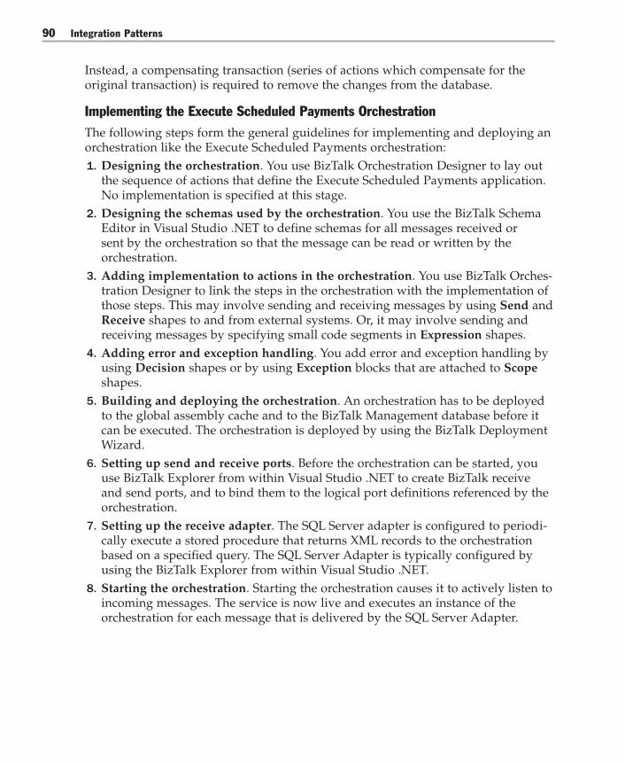
Integration Patterns90
Instead, a compensating transaction (series of actions which compensate for theoriginal transaction) is required to remove the changes from the database.
Implementing the Execute Scheduled Payments OrchestrationThe following steps form the general guidelines for implementing and deploying anorchestration like the Execute Scheduled Payments orchestration:1. Designing the orchestration. You use BizTalk Orchestration Designer to lay out
the sequence of actions that define the Execute Scheduled Payments application.No implementation is specified at this stage.
2. Designing the schemas used by the orchestration. You use the BizTalk SchemaEditor in Visual Studio .NET to define schemas for all messages received orsent by the orchestration so that the message can be read or written by theorchestration.
3. Adding implementation to actions in the orchestration. You use BizTalk Orches-tration Designer to link the steps in the orchestration with the implementation ofthose steps. This may involve sending and receiving messages by using Send andReceive shapes to and from external systems. Or, it may involve sending andreceiving messages by specifying small code segments in Expression shapes.
4. Adding error and exception handling. You add error and exception handling byusing Decision shapes or by using Exception blocks that are attached to Scopeshapes.
5. Building and deploying the orchestration. An orchestration has to be deployedto the global assembly cache and to the BizTalk Management database before itcan be executed. The orchestration is deployed by using the BizTalk DeploymentWizard.
6. Setting up send and receive ports. Before the orchestration can be started, youuse BizTalk Explorer from within Visual Studio .NET to create BizTalk receiveand send ports, and to bind them to the logical port definitions referenced by theorchestration.
7. Setting up the receive adapter. The SQL Server adapter is configured to periodi-cally execute a stored procedure that returns XML records to the orchestrationbased on a specified query. The SQL Server Adapter is typically configured byusing the BizTalk Explorer from within Visual Studio .NET.
8. Starting the orchestration. Starting the orchestration causes it to actively listen toincoming messages. The service is now live and executes an instance of theorchestration for each message that is delivered by the SQL Server Adapter.
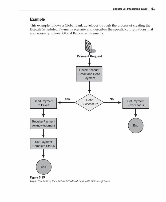
Chapter 3: Integrating Layer 91
ExampleThis example follows a Global Bank developer through the process of creating theExecute Scheduled Payments scenario and describes the specific configurations thatare necessary to meet Global Bank’s requirements.
Send Paymentto Payee
Set PaymentError Status
Receive PaymentAcknowledgment
Set PaymentComplete Status
Check AccountCredit and Debit
Payment
Yes No
End
End
DebitSuccessful?
Payment Request
Figure 3.15High-level view of the Execute Scheduled Payments business process

Integration Patterns92
To implement the Execute Scheduled Payments process, the Global Bank developerstarts by designing the process model that describes the solution. Figure 3.15 showsa high-level sketch of the process flow for this solution. The developer uses thisprocess model design to develop the Execute Scheduled Payments orchestration inthe BizTalk Server Orchestration Designer. Initially, the developer just specifies theprocess flow in the orchestration and then links the actions in the orchestration tothe implementation of those actions. For example, actions may be implemented by acall to an external Web method.
The following steps describe in detail how the Execute Scheduled Payments orches-tration implements the process model. They also describe how the completedorchestration is compiled and deployed in the Global Bank environment.
Note: Although the following steps adhere to the general implementation and deploymentguidelines presented earlier in “Implementing the Execute Scheduled Payments Orchestration,”the order and number of the steps vary slightly. The sample steps that follow reflect both theorder in which the developer creates the orchestration in BizTalk Server and the order in whichBizTalk Server presents the orchestration in the user interface. The developer also performssome steps such as error handling multiple times, according to accepted practices.
Step 1: Receiving a Payment RequestThe first shape in the orchestration is a Receive shape, which receives paymentmessages (requests). This Receive shape is linked to an orchestration port calledReceivePaymentRequest (see Figure 3.16).
Figure 3.16The first stage in the orchestration is receiving the Payment message
Whenever a payment request message is received, a new instance of the orchestra-tion is created and the message is received by this port. For information about howthese messages are generated, see “Step 10: Setting Up the SQL Server Adapter.”

Chapter 3: Integrating Layer 93
Step 2: Designing the Payment Message SchemaThe developer needs to specify an XML schema that describes the payment messageso that it can be processed by the orchestration. Normally, a developer would usethe BizTalk Schema Editor to design a schema. However, in this case, the paymentmessages are generated by using a SQL query to create an XML record set (see “Step10: Setting Up the SQL Server Adapter”). The developer can use the SQL ServerAdapter Wizard to automatically generate a schema that is appropriate for thisquery. Figure 3.17 shows the Global Bank payment schema as viewed in the BizTalkSchema Editor.
Figure 3.17The generated payment schema in the BizTalk Schema Editor

Integration Patterns94
When the SQL query is executed, multiple payment records are typically returned.The payment records must be split into separate records so that each payment canbe handled individually. The developer uses the BizTalk Schema Editor to createanother schema that is known as an envelope schema. The envelope schema repre-sents the set of payments. When the receive port is configured to use these schemas,the XML recordset that is generated is automatically split into individual XMLrecords.
Step 3: Calling a Web Service to Debit the AccountNext, the customer’s account is checked to ensure that it has sufficient funds to paythe bill. The appropriate amount is then debited from the account. The functionalityfor these steps exists on the mainframe and has been exposed as a Web servicethrough Host Integration Server (see Implementing Gateway with Host IntegrationServer 2004).
To implement this part of the orchestration, the developer uses the Add Web Refer-ence Wizard to add a Web reference to the project, just as he or she would add a Webreference to any other .NET Framework application. Adding the Web referencecreates an orchestration port that is bound to the Web service. Figure 3.18 shows theresults of adding a Web reference to an orchestration; the DebitPort is the portbound to the Web service, and CheckBalanceAndDebit and CreditAccount repre-sent some of the Web methods that this Web serviceimplements.
In addition, the Add Web Reference Wizard generates XML schemas that representthe request-response messages for each of the Web methods exposed by the Webservice. The Add Web Reference Wizard also creates corresponding orchestrationmessage types. The developer then creates instances of the orchestration messagetypes CheckBalanceAndDebit_request and CheckBalanceAndDebit_response. Theseinstances are called DebitRequest and DebitResponse respectively.

Chapter 3: Integrating Layer 95
Figure 3.18Preparing and sending a message to a Web method
The DebitRequest message is initialized using a Transform shape calledTransformPayment2DebitRequest (see Figure 3.19). This shape applies an Exten-sible Stylesheet Language for Transformations (XSLT) transformation to the incom-ing Payment message and initializes the DebitRequest message.
The DebitRequest message is then sent to the Web method CheckBalanceAndDebitby the SendDebitRequest shape, which ensures the account has sufficient funds.The appropriate amount is then debited from the account. The Web method returnsthe DebitResponse message to the ReceiveDebitResponse shape. This message hasfields that contain the new account balance and the status of the debit action.

Integration Patterns96
Step 4: Handling ExceptionsUnder some circumstances, the CheckBalanceAndDebit Web method mayreturn an exception. For example, an exception is generated if a request toCheckBalanceAndDebit specifies an invalid account number. The orchestrationmust handle this exception by providing an exception handler that specifies anappropriate action under these conditions.
Exception handling can be set at various levels of scope within the orchestration. Inthis instance, the Web method request and response are enclosed by a Scope shape.The Scope shape has specific exception handling code attached (see Catch SOAPException in Figure 3.18).
In this example, the exception handling is simple. The code in the Set Error StatusExpression shape sets the value of the errorStatus orchestration variable to 1, toindicate that a Web service exception has occurred. This value is checked later in theorchestration (see “Step 5: Checking for Errors”).
Note: This example assumes that if an exception is generated, no debit occurs. Therefore, nocompensation logic is required in this case. For an example that requires compensation logic,see “Step 7: Compensating for Payment Errors.”
Step 5: Checking for ErrorsStep 4 described how the Web method can throw exceptions, and how these excep-tions are caught and handled. Additionally, the Web method response message(DebitResponse) returns a status code that may also indicate an error such as insuffi-cient funds in the account.
Exceptions and error status messages differ in their recoverability. An exception isreserved for situations where a fundamental error has occurred that is not likely tobe recoverable. Step 4 provides an example of an exception being thrown for aninvalid account number. This situation may indicate a significant problem (a dataerror) that is not likely to be recoverable.
An error status message is reserved for an error status that is returned by a Webmethod and that indicates a business error occurred where the business error islikely to be recoverable. An example of a business error that is likely to be recover-able is an attempt to execute a payment when there are insufficient funds in theaccount.
When the Web method returns a response message, the response message containsa Boolean status field. The orchestration checks the value of this field to determineif the Web method call was successful. In this case, the Web method call is successfulif the appropriate amount was debited from the account. To check the value of thefield, a Decide shape is used to test the value of the status field as shown in Figure3.19.
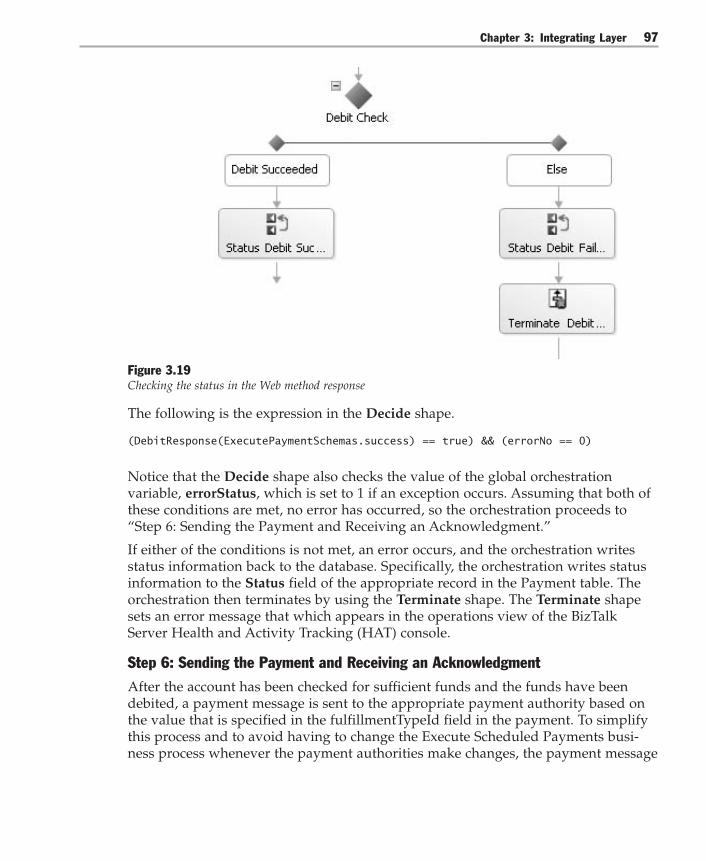
Chapter 3: Integrating Layer 97
Figure 3.19Checking the status in the Web method response
The following is the expression in the Decide shape.
(DebitResponse(ExecutePaymentSchemas.success) == true) && (errorNo == 0)
Notice that the Decide shape also checks the value of the global orchestrationvariable, errorStatus, which is set to 1 if an exception occurs. Assuming that both ofthese conditions are met, no error has occurred, so the orchestration proceeds to“Step 6: Sending the Payment and Receiving an Acknowledgment.”
If either of the conditions is not met, an error occurs, and the orchestration writesstatus information back to the database. Specifically, the orchestration writes statusinformation to the Status field of the appropriate record in the Payment table. Theorchestration then terminates by using the Terminate shape. The Terminate shapesets an error message that which appears in the operations view of the BizTalkServer Health and Activity Tracking (HAT) console.
Step 6: Sending the Payment and Receiving an AcknowledgmentAfter the account has been checked for sufficient funds and the funds have beendebited, a payment message is sent to the appropriate payment authority based onthe value that is specified in the fulfillmentTypeId field in the payment. To simplifythis process and to avoid having to change the Execute Scheduled Payments busi-ness process whenever the payment authorities make changes, the payment message

Integration Patterns98
is sent to a Message Broker. Message Broker is implemented with BizTalk Server also,For additional information, see Implementing Message Broker with BizTalk Server 2004.
Message Broker selects the appropriate payment authority based on thefulfillmentTypeId field, transforms the message to the appropriate format for thatpayment authority, and then sends the message. This series of events is shown inFigure 3.20.
Figure 3.20Sending the payment request and receiving a response
After the payment message is sent to the payment authority through the MessageBroker, the payment authority sends an acknowledgement back to theReceivePaymentResponse port. When these acknowledgement responses arrive,they need to be correlated to the correct instance of the payment orchestration forwhich they are intended.
To correlate the response message with the orchestration instance, the developercreates a correlation type that specifies certain fields in the message. These fields areguaranteed to be unique across all instances of the orchestration; this example usesthe PaymentId field. The developer creates an instance of this correlation type calleda correlation set. The correlation set is be initialized with the actual value of thePaymentId from the PaymentRequest message when that message is sent out theSendPaymentRequest orchestration port. Lastly, the developer configures theReceive Payee Response shape to wait for an acknowledgment message thatmatches this correlation set.

Chapter 3: Integrating Layer 99
Now, when the payment authority sends an acknowledgment back, the acknowledg-ment includes the PaymentId. The BizTalk orchestration engine automatically passesthe acknowledgment to the instance of the ReceivePaymentResponse port with acorrelation set that equates to this PaymentId.
Step 7: Compensating for Payment ErrorsAt this stage in the orchestration, the following errors could have occurred:● No response was received from the payment authority. This error could occur
either because the payment authority never received the Payment message orbecause of some fault with the payment authority system.
● The response indicated that payment could not be processed. This error couldoccur for a number of reasons, such as invalid payee details or incorrect paymentdetails.
Exceptions and errors are handled in the same way as in steps 4 and 5. One or moreexception handlers catch exceptions, and a Decide shape checks the status fields inthe response messages.
Note: The Send Payment Request Tx scope shape can have a timeout attached so that if noresponse is received within a certain time, the orchestration automatically generates anexception.
Compensation processing is also needed at this point. Compensation processingreverses the effects of earlier transactions that have occurred in the business process.In this example, the customer account is debited before the payment request is sentto the payment authority. It is not possible to roll back this transaction because it hasalready been committed and the money has been deducted from the customer’saccount balance. Because the bill has not been paid, the compensation processingmust reverse the effects of this transaction by crediting the money back to theaccount.

Integration Patterns100
Figure 3.21Compensation logic for failed payments
Figure 3.21 shows how the compensation is added to the Scope shape that sends thepayment request message. The compensation logic transforms the payment messageto create a Web method request that can be sent to the CreditAccount Web method.
Note: A real-world scenario would require additional error handling around the compensationcode, but this has been excluded in this example for simplicity.
Step 8: Deploying the OrchestrationThe orchestration, schemas, and maps now must be compiled to a .NET Frameworkassembly, and then the assembly must be deployed to the BizTalk Server Configura-tion database and to the global assembly cache. To deploy to the global assemblycache, the assembly must be signed with a strong name.
Before building the assembly, create a key file by using the following command atthe command prompt.
>sn –k ExecutePayment.snk
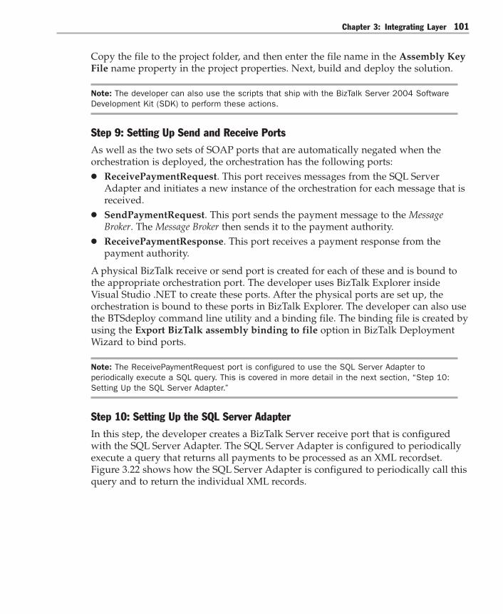
Chapter 3: Integrating Layer 101
Copy the file to the project folder, and then enter the file name in the Assembly KeyFile name property in the project properties. Next, build and deploy the solution.
Note: The developer can also use the scripts that ship with the BizTalk Server 2004 SoftwareDevelopment Kit (SDK) to perform these actions.
Step 9: Setting Up Send and Receive PortsAs well as the two sets of SOAP ports that are automatically negated when theorchestration is deployed, the orchestration has the following ports:● ReceivePaymentRequest. This port receives messages from the SQL Server
Adapter and initiates a new instance of the orchestration for each message that isreceived.
● SendPaymentRequest. This port sends the payment message to the MessageBroker. The Message Broker then sends it to the payment authority.
● ReceivePaymentResponse. This port receives a payment response from thepayment authority.
A physical BizTalk receive or send port is created for each of these and is bound tothe appropriate orchestration port. The developer uses BizTalk Explorer insideVisual Studio .NET to create these ports. After the physical ports are set up, theorchestration is bound to these ports in BizTalk Explorer. The developer can also usethe BTSdeploy command line utility and a binding file. The binding file is created byusing the Export BizTalk assembly binding to file option in BizTalk DeploymentWizard to bind ports.
Note: The ReceivePaymentRequest port is configured to use the SQL Server Adapter toperiodically execute a SQL query. This is covered in more detail in the next section, “Step 10:Setting Up the SQL Server Adapter.”
Step 10: Setting Up the SQL Server AdapterIn this step, the developer creates a BizTalk Server receive port that is configuredwith the SQL Server Adapter. The SQL Server Adapter is configured to periodicallyexecute a query that returns all payments to be processed as an XML recordset.Figure 3.22 shows how the SQL Server Adapter is configured to periodically call thisquery and to return the individual XML records.
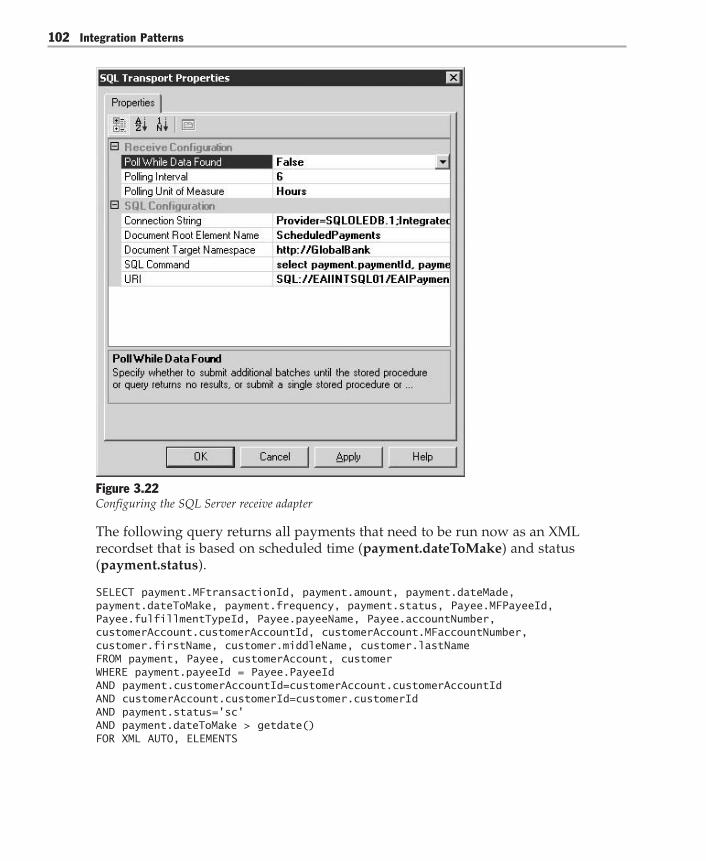
Integration Patterns102
Figure 3.22Configuring the SQL Server receive adapter
The following query returns all payments that need to be run now as an XMLrecordset that is based on scheduled time (payment.dateToMake) and status(payment.status).
SELECT payment.MFtransactionId, payment.amount, payment.dateMade,payment.dateToMake, payment.frequency, payment.status, Payee.MFPayeeId,Payee.fulfillmentTypeId, Payee.payeeName, Payee.accountNumber,customerAccount.customerAccountId, customerAccount.MFaccountNumber,customer.firstName, customer.middleName, customer.lastNameFROM payment, Payee, customerAccount, customerWHERE payment.payeeId = Payee.PayeeIdAND payment.customerAccountId=customerAccount.customerAccountIdAND customerAccount.customerId=customer.customerIdAND payment.status='sc'AND payment.dateToMake > getdate()FOR XML AUTO, ELEMENTS

Chapter 3: Integrating Layer 103
As described in steps 1 and 2, the record set returned is split into individual pay-ment messages by using an XML envelope schema, and each of these messagescreates a new instance of the orchestration.
Step 11: Starting the OrchestrationFinally, the developer uses BizTalk Explorer to bind the physical receive and sendports created in steps 9 and 10 to the ports in the orchestration. The developer thenstarts the orchestration. Now, the SQL Server Adapter should execute the SQL queryevery six hours, and one instance of the orchestration should be created for eachpayment record that is returned. These orchestrations execute the scheduled pay-ment as described and terminate upon completion.
Resulting ContextThis implementation of Process Integration results in the following benefits andliabilities.
Benefits● Maintainability. Creating a separate process integration layer allows users to
define and maintain the business process independent from the implementationof the individual functions. This increases maintainability and reduces the skillset requirements for the personnel who maintain the process definition. BizTalkServer orchestration supports this by defining the business process flow indepen-dently of the binding to individual actions that make up that flow.
● Reusability. Because the existing applications are not dependent on the processmanagement layer, the functions inside these applications can be reused inmultiple process definitions.
● Flexibility. BizTalk orchestration supports a variety of configurations that wouldbe difficult to implement in many traditional programming models. For example,BizTalk orchestration supports parallel execution of multiple tasks, synchroniza-tion points, timeouts, and escalations. Supporting a variety of configurationsgives the process manager the flexibility to adapt to many different businessrequirements.
● Reporting. Because the process instances are maintained centrally, it becomesfeasible to extract statistical information that spans multiple process steps andprocess instances. Such reports can tell you the average length of time it takes tofulfill an order and the number of orders that are on hold because of insufficientinventory. BizTalk Server provides extensive real-time reporting, and in addition,it uses SQL Server Analysis Services to provide comprehensive reporting acrossaggregated business results.

Integration Patterns104
Liabilities● Potential bottleneck. Managing a large number of process instances in a central
process manager component may present a run-time bottleneck. However,BizTalk Server provides mechanisms to manage the lifetime of a large number ofconcurrently running orchestrations. These mechanisms include dehydration andrehydration of business processes that are currently blocked.
● Temptation to overuse. This liability is the flipside of the flexibility inherent inProcess Integration solutions. Because BizTalk orchestration can be used to solvenearly any integration problem, the temptation is to apply BizTalk orchestrationto all integration problems. This can lead to overarchitected solutions and some-times to inefficient solutions. For example, many developers might be tempted touse Process Integration in cases where Message Broker would beperfectly appropriate to address the requirements.
Testing ConsiderationsSeparating the process definition from the functions provided by the applicationsmeans that you can test each business function (service) individually by creatingsimple test drivers that call the functions and verify the results. For example, youcan test the Gateway Web service by using a.NET Framework application to call theWeb service, by supplying various test parameters, and by validating the responses.
The advantage of using a commercial process manager such as BizTalk Server 2004is that it is designed to handle complex issues that are related to throughput, thread-ing, transactions, locking, and performance bottlenecks. This means that you onlyneed to perform minimal testing of these aspects of the application. This also meansthat more testing effort can concentrate on the unit tests of the individual steps ofthe business process and on the integration of these steps into a complete businessprocess.
Security ConsiderationsApplications built using BizTalk Server orchestration typically access multiplebusiness systems that encapsulate the individual steps of the business process. Thesebusiness systems often provide their own authentication mechanism, usually a username and password. A common requirement when using BizTalk orchestration toaccess these systems is for the orchestration to supply credentials for the user who isrepresented by this instance of the business process.
For example, a business process may be initiated by many users filling out aMicrosoft Office InfoPath™ form and sending it in a SOAP message to BizTalkServer. The messages initiate a new instance of the orchestration for each user. Theseinstances then access business systems such as an Enterprise Resource Planning

Chapter 3: Integrating Layer 105
(ERP) system by using the user’s credentials for that system. Because it is not practi-cal to request the credentials from the user, credentials are either encoded in themessage itself or accessed by BizTalk from a secure store.
BizTalk Server provides the enterprise single sign-on (SSO) system to store creden-tial information. SSO provides a secured store, which is based on the user’s securitycontext, and stores security and state information that is pertinent to that securitycontext. In the earlier example, the security context of the user filling out theInfoPath form can be used to retrieve the user name and password for the ERPsystem from SSO. The orchestration can then access the ERP system on that user’sbehalf.
Operational ConsiderationsBizTalk Server orchestrations are bound to a BizTalk Server host. A BizTalk Serverhost is an engine for messaging and orchestration. An instance of a BizTalk Serverhost can be created on each BizTalk Server computer in the BizTalk Server group,which results in the creation of a process on a computer through a Windows service.The process then executes instances of the orchestration.
You can use the BizTalk Server Administration console to create additional hosts.You can then bind the additional hosts to orchestrations and map to servers in theBizTalk Server group. This allows orchestrations to be deployed to any combinationof servers in the BizTalk Server group. Therefore, the business application can bedistributed across the servers in your enterprise as needed.
Related PatternsProcess Manager [Hohpe04] describes the internal function and implementation ofthe process manager component.
Acknowledgments[Hohpe04] Hohpe, Gregor, and Bobby Woolf, Enterprise Integration Patterns:Designing, Building, and Deploying Messaging Solutions. Addison-Wesley, 2004.
[Chapell03] David Chappell, Chappell & Associates. “Understanding BizTalk Server2004.” Microsoft Corporation, 2003. Available athttp://go.microsoft.com/fwlink/?LinkId=21313.
Integration Patterns106
Portal Integration
ContextMany business functions require users to access information that resides in multipledisparate systems. For example, a customer might call a service representative toplace a new order. However, before the service representative accepts a new order,he or she has to verify the customer’s payment history in the accounting system toensure that the customer is in good standing. Switching between systems makes theservice representative’s work tedious and error-prone.
ProblemHow can users efficiently perform tasks that require access to information thatresides in multiple disparate systems?
ForcesTo solve this problem, you need to consider the following forces:● It is still very common for an end user to have to manually copy information
from one system to another. This type of integration is often referred to humor-ously as “swivel chair integration” because the user has to access multiple sys-tems, often from multiple terminal screens. The user views the information onone screen and then swivels to another screen to enter data based on the informa-tion from the first screen. Obviously, this type of manual integration is veryinefficient and error prone.
● Process Integration can automate tasks that combine data and functions frommultiple systems, thereby alleviating the need for users to access multiple sys-tems directly. However, Process Integration requires a good understanding of thebusiness process so that the business process can be accurately represented in aprocess model. This is often not the case because users make improvised deci-sions based on the information they see.
● Entity Aggregation allows multiple systems to share data, which enables the userto access all required information from a single point. However, Entity Aggrega-tion is often impossible or not economical due to strong semantic dissonancebetween the individual systems and lack of a common vocabularybetween systems and people.
● Reading data from an application is generally simpler and less risky than updat-ing information. This is especially true in cases such as Data Integration, whichdirectly accesses application data and bypasses the business and validation logic.

Chapter 3: Integrating Layer 107
SolutionCreate a portal application that displays the information retrieved from multipleapplications in a unified user interface. The user can then perform the required tasksbased on the information displayed in this portal.
Portal Engine
Application Application Application
User Interface
Figure 3.23Portal Integration
Portal Integration is a comparatively simple form of integration. It is popular becauseit is typically much easier to implement and less intrusive than more sophisticatedtypes of integration, such as Process Integration. With Portal Integration, the businessprocess that describes the sequence of tasks does not have to be represented in aprecise process model, but instead resides in the user’s head. This enables the enduser to compensate for mismatches in semantics between the individual systems andto make a case-by-case decision. This approach is naturally less efficient than Process

Integration Patterns108
Integration, but it gives the user flexibility and it is typically much faster to imple-ment. In many cases, Portal Integration can be used as an intermediate solution untilbusiness processes are better understood and can be incorporated into a processmodel, thus enabling the transition to Process Integration.
The portal engine shown in Figure 3.23 interacts with the individual applicationsusing Data Integration, Functional Integration, or Presentation Integration. Because theprimary purpose of the portal is the display of information, Portal Integration worksparticularly well with simpler forms of connectivity, such as Data Integration orPresentation Integration.
Portal Integration comes in a variety of flavors from very simple to fairly complex.The following list categorizes the different variants:● Display-only. The simplest form of Portal Integration simply displays data in
different areas of the screen. Information from each application is mapped to arectangular area of the screen, also referred to as a pane. This display allows theuser to view information retrieved from multiple applications on a single screen.No other functionality is provided.
● Simple post-processing. Instead of presenting the data received from eachindividual system, many portals add simple rules that help the user make deci-sions. For example, if the billing system reports that a customer payment isoverdue, the portal would list this as an exception in bold red letters at the top ofthe screen instead of showing the history of all payments received. This type offunctionality helps turn raw data into useful information for the user.
● Single application interaction. This variant displays data in different areas of thescreen, but it also allows the user to issue commands to one system at a time. Thisextra functionality enables the user to view information from multiple systemsand use the resulting data to perform a business function that is limited to asingle system.
● Cross-pane interactivity. In many cases, the information to be displayed in onepane depends on a user selection in another pane. For example, a list of custom-ers might be retrieved from the customer relationship management (CRM)system. When the user selects a customer’s name from the list, the portal re-trieves the selected customer’s payment history from the billing system anddisplays it in a separate pane. To automate these steps, basic interactionbetween different portal panes is required. This type of portal speeds up theuser’s tasks without requiring full integration between systems. However, thistype of portal does require the availability of common keys, such as a customeridentifier (ID), that function across multiple systems. With this type of portal, thedevelopment of the interaction is often difficult to test and reuse.
The Portal Integration solution relies on interplay between the solution componentsthat are described in Table 3.3.

Chapter 3: Integrating Layer 109
Table 3.3: Portal Integration Solution Components
Component Responsibilities Collaborators
Portal engine – Extract information from existing applications – Render information into a unified user interface Applications
Application Host relevant business data None
ExampleMany customer service functions require access to a range of customer data. Forexample, a customer may call to place a new order, check whether a payment hasbeen received, and change his or her phone number. Often, this type of informationis stored in many different systems, such as the order management system, thebilling system, or the complaint system. Giving a customer service representative aunified view of the various records for a customer can be enormously helpful inproviding efficient and effective service to the customer. A similar or reduced ver-sion of the portal could also be presented directly to the consumer on the company’sWeb site.
Resulting ContextPortal Integration results in the following benefits and liabilities:
Benefits● Non-intrusiveness. Because its primary function is the retrieval and display of
information, Portal Integration can typically be added to existing systems withoutdisturbing the existing functionality. This is particularly true if Portal Integrationuses Data Integration for the retrieval of data from the individual systems.
● Speed of implementation. Adding a portal to existing applications can often beaccomplished in a matter of days or weeks, whereas a full integration of thesystems could take many months. Many vendors offer Portal Integration platformsin combination with a suite of prefabricated panes that integrate with manypopular enterprise applications and data sources.
● Flexibility. Because the user makes the decisions, Portal Integration can be used insituations where business rules are not well understood or not agreed upon.

Integration Patterns110
Liabilities● Inefficient. Portal integration is best suited to the automation of simple tasks and
processes because it still requires manual interaction by the user. For example,because most portals allow the user to interact with only one application at atime, the user might have to perform multiple manual actions in sequence tocomplete a complex business function. This makes Portal Integration unsuitablefor high-volume applications. In these situations, Process Integration is generally abetter solution because the sequence of steps can be encoded in a process modeland run automatically by the process manager.
● Error-prone. When using Portal Integration, the user makes business decisionsand determines the sequence of tasks to be performed. While this providesflexibility, it also introduces the risk of human error. Therefore, Portal Integrationis not well suited to integrations that require strict repetition of a defined busi-ness process. Process Integration is generally a better choice in those scenarios.
4System Connections
The previous chapter described different strategies for the design of an integrationlayer and the tradeoffs involved in choosing an alternative. After you decide to usean integrating layer, you must then decide exactly how you are going to connecteach system that you intend to integrate.
As you consider how to connect to different information systems, you will encoun-ter a mix of technical architectures. Each technical architecture is designed to allowcertain types of access and to restrict others. These access restrictions constrain theset of integration options that are available to you. This chapter discusses a series ofrelated patterns that will help you analyze the alternative methods and the tradeoffsto consider when you choose your system connections.
Connecting to Layered ApplicationsWhen trying to find connection points to an existing application, you need to studythe way these applications are structured. The prevailing architectural style forbusiness applications is Layered Application. Many applications fall into the morespecific form of the Three-Layered Services Application pattern [Trowbridge03]. Thecomponents of this pattern are shown in Figure 4.1.

Integration Patterns112
Data Layer
PresentationLayer
Business Logic Layer
Figure 4.1A three-layered services application
This architectural style defines three distinct layers:● Presentation layer. The presentation layer displays information to the end user
and allows for user input.● Business logic layer. The business logic layer contains business functions that act
on the business data● Data layer. The data layer stores data persistently in a data store. This layer is
also known as the resource layer.
Each application layer presents an opportunity for an application to interact withthe integration layer, as shown in Figure 4.2.
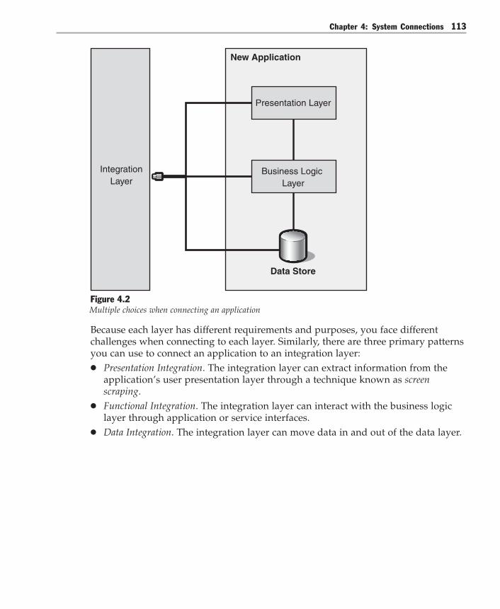
Chapter 4: System Connections 113
New Application
IntegrationLayer
Business Logic Layer
Presentation Layer
Data Store
Figure 4.2Multiple choices when connecting an application
Because each layer has different requirements and purposes, you face differentchallenges when connecting to each layer. Similarly, there are three primary patternsyou can use to connect an application to an integration layer:● Presentation Integration. The integration layer can extract information from the
application’s user presentation layer through a technique known as screenscraping.
● Functional Integration. The integration layer can interact with the business logiclayer through application or service interfaces.
● Data Integration. The integration layer can move data in and out of the data layer.

Integration Patterns114
To make an informed choice about which pattern to use, you must know the optionsthat are viable, and you must evaluate their impact on the overall integration archi-tecture. This chapter describes each pattern and elaborates on the benefits andliabilities of each one.
As in other chapters, this chapter uses visual models to show the associationsbetween the patterns. Figure 4.3 shows the patterns as circles and simple associa-tions between them as lines. As the discussion progresses, more complex patternrelationships build upon this basic diagram.
Data Integration Functional Integration Presentation Integration
Figure 4.3System connection patterns
The first kind of integration to consider is Data Integration.
Data IntegrationMany applications keep large volumes of data in data stores such as flat files andrelational, hierarchical, and object-oriented databases. Other applications that needthis information can access it directly from these data stores.
Connecting applications through the data store is relatively simple. Usually, you useFTP, scheduled batch files, database management system (DBMS) utilities, extracttransform and load (ETL) tools, and integration servers.
If you decide to integrate at the data layer, there are three patterns that represent thethree types of data integration to consider: Shared Database [Hohpe04], Maintain DataCopies [Teale03], and File Transfer [Hohpe04]. These patterns are shown in Figure 4.4.

Chapter 4: System Connections 115
Shared Database Maintain Data Copies
Data Integration
File Transfer
Figure 4.4Three kinds of data integration
Figure 4.4 introduces a new pattern relationship to the visual model from Figure 4.3.The triangle indicates refinement between the base pattern (Data Integration) and thederivative patterns (Shared Database, Maintain Data Copies, and File Transfer). Moreprecisely, this relationship is defined as follows:
“A specific pattern refines a more abstract pattern if the specific pattern’s fulldescription is a direct extension of the more general pattern. That is, the specificpattern must deal with a specialization of the problem the general pattern ad-dresses, must have a similar (but more specialized) solution structure, and mustaddress the same forces as the more general pattern, but may also address addi-tional forces. To make an analogy with object-oriented programming … the refinesrelationship is similar to inheritance.” [Noble98]
Applying this relationship to the problem of data integration means that if youdecide to integrate systems at the data layer, you must further refine your decisionby choosing one of three alternatives. You could share a single instance of a databasebetween multiple applications by using the Shared Database pattern, as shown inFigure 4.5.

Integration Patterns116
Application Application
Data Store
Application
Figure 4.5Multiple applications sharing the same data store
Another approach is to create multiple copies of a database and distribute themthroughout your enterprise according to the Maintain Data Copies pattern. If you dothis, you must then maintain these separate copies, which introduces synchroniza-tion and replication. Figure 4.6 shows the Data Replication pattern, which refinesMaintain Data Copies.
Application
Business Logic Layer
PresentationLayer
Data Store
Other Applications
Figure 4.6Data Replication, a refinement of Maintain Data Copies

Chapter 4: System Connections 117
Yet another approach is to use File Transfer. In this pattern, one application producesa file and transfers it so that other applications can consume it. Files can then beproduced at regular intervals to synchronize two or more systems.
The Data Integration pattern, later in this chapter, describes these alternatives indetail and provides the benefits and liabilities of each approach. This discussionshould help you choose the kind of data integration that is appropriate for yourrequirements.
Using Data Integration is made easier by the abundance of tool support provided bymany companies. However, in spite of the low cost and the maturity of the tools,accessing the data store is not viable in some cases. A less invasive way of connect-ing applications is to connect through the presentation layer.
Presentation IntegrationWhen applications that have user interfaces join an integration architecture, otherapplications can connect to them through the presentation byte stream as shown inFigure 4.7.
Other Applications
Application
Business Logic Layer
Presentation Layer
Data Store
Terminal Emulator
Figure 4.7Connecting to an application through the presentation layer

Integration Patterns118
Presentation connectivity represents the least invasive way of connecting applica-tions because the other applications appear to the host application as humans whoare interacting through the user interface. Therefore, this form of integration doesnot require any changes to the host. The disadvantage is that simulating user inter-action is cumbersome and inefficient. It requires parsing the data or functionalityout of the byte stream, which effectively reverses the transformations performed bythe presentation logic. In addition, applications that connect through the presenta-tion layer can only access what is also available to a human user. The granularity ofthe exposed data and functionality is very coarse; burying potentially-rich APIs.
One advantage of Presentation Integration is that it can be an inexpensive way tointegrate applications. Although the connection is inexpensive, it is also easilydisrupted. By its very nature, presentation integration is tightly coupled to the hostapplication’s presentation. If the application’s presentation changes, the presentationintegration solution must also change.
Instead of sharing data or parsing through a byte stream to access a system’s func-tionality, it is often preferable to access a system’s business logic directly throughFunctional Integration.
Functional IntegrationBy connecting directly to the business logic layer, Functional Integration enables otherapplications and services to take advantage of the business logic that is encapsulatedin other systems, as shown in Figure 4.8.
Data Layer
PresentationLayer
Other ApplicationsBusiness Logic
Layer
Figure 4.8Integrating applications and services at the business logic layer
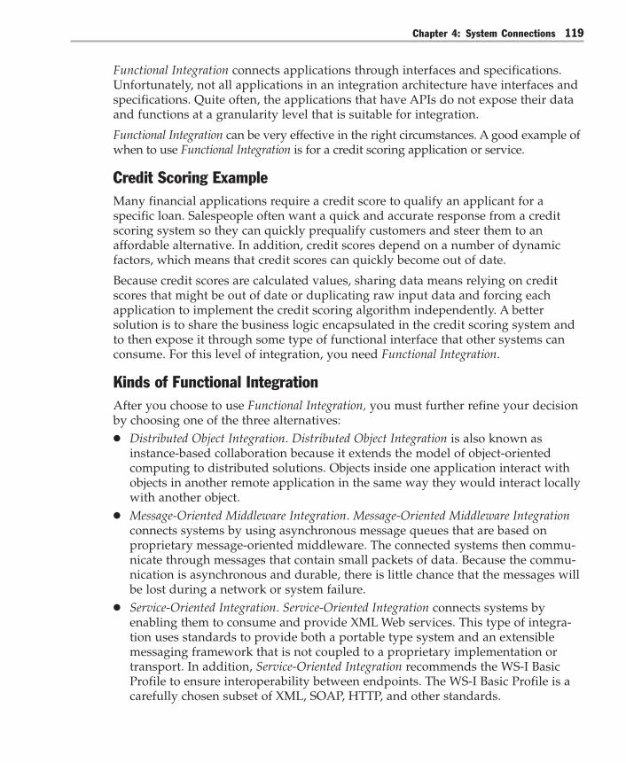
Chapter 4: System Connections 119
Functional Integration connects applications through interfaces and specifications.Unfortunately, not all applications in an integration architecture have interfaces andspecifications. Quite often, the applications that have APIs do not expose their dataand functions at a granularity level that is suitable for integration.
Functional Integration can be very effective in the right circumstances. A good example ofwhen to use Functional Integration is for a credit scoring application or service.
Credit Scoring ExampleMany financial applications require a credit score to qualify an applicant for aspecific loan. Salespeople often want a quick and accurate response from a creditscoring system so they can quickly prequalify customers and steer them to anaffordable alternative. In addition, credit scores depend on a number of dynamicfactors, which means that credit scores can quickly become out of date.
Because credit scores are calculated values, sharing data means relying on creditscores that might be out of date or duplicating raw input data and forcing eachapplication to implement the credit scoring algorithm independently. A bettersolution is to share the business logic encapsulated in the credit scoring system andto then expose it through some type of functional interface that other systems canconsume. For this level of integration, you need Functional Integration.
Kinds of Functional IntegrationAfter you choose to use Functional Integration, you must further refine your decisionby choosing one of the three alternatives:● Distributed Object Integration. Distributed Object Integration is also known as
instance-based collaboration because it extends the model of object-orientedcomputing to distributed solutions. Objects inside one application interact withobjects in another remote application in the same way they would interact locallywith another object.
● Message-Oriented Middleware Integration. Message-Oriented Middleware Integrationconnects systems by using asynchronous message queues that are based onproprietary message-oriented middleware. The connected systems then commu-nicate through messages that contain small packets of data. Because the commu-nication is asynchronous and durable, there is little chance that the messages willbe lost during a network or system failure.
● Service-Oriented Integration. Service-Oriented Integration connects systems byenabling them to consume and provide XML Web services. This type of integra-tion uses standards to provide both a portable type system and an extensiblemessaging framework that is not coupled to a proprietary implementation ortransport. In addition, Service-Oriented Integration recommends the WS-I BasicProfile to ensure interoperability between endpoints. The WS-I Basic Profile is acarefully chosen subset of XML, SOAP, HTTP, and other standards.

Integration Patterns120
Note: The term service is used in many different ways in the context of software engineer-ing. It is also used in at least seven levels of scope: operating system, process, object,distributed object, proprietary message-oriented middleware, logical, and XML Web services.This guide uses the term service to mean XML Web services unless indicated otherwise.
Figure 4.9 shows these three alternatives as distinct derivatives, or refinementpatterns, of Functional Integration.
Distributed ObjectIntegration
Message-OrientedMiddleware Integration
Functional Integration
Service-OrientedIntegration
Figure 4.9Three kinds of Functional Integration
Later in this chapter, the Functional Integration pattern describes these alternatives indetail and discusses the benefits and liabilities of each approach. This discussionshould help you choose the kind of functional integration that is appropriate foryour requirements.
System Connection PatternsData, presentation, and functional integration represent ways in which seasonedintegration architects connect applications. But given your specific requirements,how do you connect applications within your integration architecture?
Sometimes the applications you are integrating limit your choices. If there is morethan one way you can connect them, you must evaluate the tradeoffs associated

Chapter 4: System Connections 121
with each potential choice. The Data Integration, Presentation Integration, and Func-tional Integration patterns later in this chapter distill the knowledge required to makean informed decision.
Two general points are worth noting. First, an application that uses one style ofconnection can communicate with another application that uses a different style. Forexample, Presentation Integration may be the only way to extract data from a preexist-ing application, but you can still insert this data into the target application usingData Integration. Second, despite sometimes similar names, a specific integrationlayer pattern can be used with any system connection pattern. For example, a PortalIntegration solution can extract data from existing applications by using PresentationIntegration, Functional Integration, or Data Integration.
Figure 4.10 shows three system connection patterns, with derivative patterns andassociations.
SharedDatabase
MaintainData Copies
DataIntegration
FileTransfer
DistributedObject
Integration
Message-Oriented
MiddlewareIntegration
FunctionalIntegration
Service-Oriented
Integration
PresentationIntegration
Figure 4.10System connection patterns and their relationships
Table 4.1 summarizes these patterns and provides the problem/solution pairs theyrepresent.

Integration Patterns122
Table 4.1: System Connections Patterns
Pattern or pattlet Problem Solution Associated implementations
Data Integration How do you integrate Integrate applicationsinformation systems at the logical data layer.that were not Use a Shared Database,designed to work File Transfer, or Maintaintogether? Data Copies.
Shared Database How can multiple Have multiple applica-[Hohpe04] applications work tions store data in a
together and exchange single database. Defineinformation? a schema that handles
the needs of allrelevant applications.
Maintain Data How can multiple Have multiple applica-Copies [Teale03] applications work tions access multiple
together and exchange copies of the same data.information? Maintain state integrity
between copies.
File Transfer How can multiple At regular intervals,[Hohpe04] applications work have each application
together and produce files thatexchange contain the informationinformation? that the other applica-
tions must consume.After you create it, donot maintain the file.
Functional How do you integrate Integrate applications atIntegration information systems the logical business layer.
that were not Use Distributed Objectdesigned to work Integration, (proprietary)together? Message-Oriented
Middleware Integration,or Service-OrientedIntegration.
Distributed How do you integrate Develop systems thatObject applications at the have object interfacesIntegration logical business that can be consumed(see also layer? remotely by otherRemote systems.ProcedureInvocation[Hohpe04])

Chapter 4: System Connections 123
Pattern or pattlet Problem Solution Associated implementations
Message- How do you integrate Use proprietaryOriented applications at the message-orientedMiddleware logical business layer? middleware to sendIntegration messages(see also asynchronously.Messaging[Hohpe04])
Service-Oriented How do you integrate Use Web services to ImplementingIntegration applications at the expose interfaces that Service-Oriented
logical business layer? can be consumed Integration withremotely by other ASP.NET, orsystems. Implementing Service-
Oriented Integrationwith BizTalk Server2004.
Presentation How do you integrate Access the application’sIntegration information systems functionality through the
that were not designed user interface byto work together? simulating a user’s input
and reading data fromthe screen display.

Integration Patterns124
Data Integration
ContextEnterprise information systems are comprised of a variety of data storage systems,which vary in complexity and in the ways they access internal data. An example ofa simple data storage system is a flat file. An example of a far more complex datastorage system is a Database Management System (DBMS) server farm.
ProblemHow do you integrate information systems that were not designed to worktogether?
Forces● Most enterprises contain multiple systems that were never designed to work
together. The business units that fund these information systems are primarilyconcerned with functional requirements rather than technical architectures.Because information systems vary greatly in terms of technical architecture,enterprises often have a mix of systems, and these systems have incompatiblearchitectures.
● Many applications are organized into three logical layers: presentation, businesslogic, and data.
● When you integrate multiple systems, you usually want to be as noninvasive aspossible. Any change to an existing production system is a risk, so it is wise to tryto fulfill the needs of other systems and users while minimizing disturbance tothe existing systems.
● Likewise, you usually want to isolate applications’ internal data structures.Isolation means that changes to one application’s internal structures or businesslogic do not affect other applications. Without isolated data structures, a smallchange inside an application could cause a ripple effect and require changes inmany dependent applications.
● Reading data from a system usually requires little or no business logic or valida-tion. In these cases, it can be more efficient to access raw data that a businesslayer has not modified.
● Many preexisting applications couple business and presentation logic so that thebusiness logic is not accessible externally. In other cases, the business logic maybe implemented in a specific programming language without support for remoteaccess. Both scenarios limit the potential to connect to an application’s businesslogic layer.
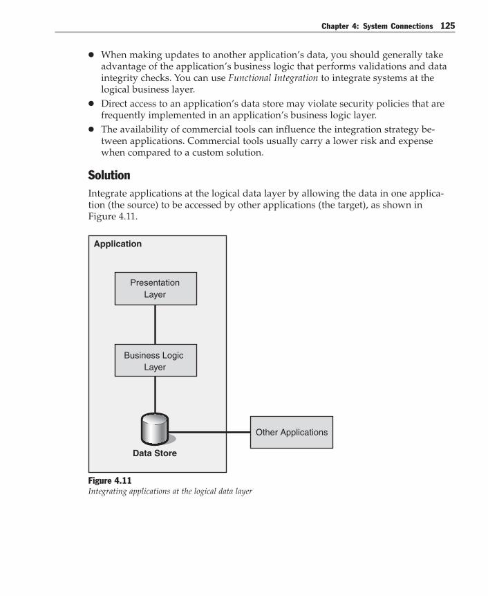
Chapter 4: System Connections 125
● When making updates to another application’s data, you should generally takeadvantage of the application’s business logic that performs validations and dataintegrity checks. You can use Functional Integration to integrate systems at thelogical business layer.
● Direct access to an application’s data store may violate security policies that arefrequently implemented in an application’s business logic layer.
● The availability of commercial tools can influence the integration strategy be-tween applications. Commercial tools usually carry a lower risk and expensewhen compared to a custom solution.
SolutionIntegrate applications at the logical data layer by allowing the data in one applica-tion (the source) to be accessed by other applications (the target), as shown inFigure 4.11.
Application
Business Logic Layer
PresentationLayer
Data Store
Other Applications
Figure 4.11Integrating applications at the logical data layer
Integration Patterns126
To connect applications at the logical data layer, use one or more of the followingpatterns:● Shared Database. All applications that you are integrating read data directly from
the same database.● Maintain Data Copies. Maintain copies of the application’s database so that other
applications can read the data (and potentially update it).● File Transfer. Make the data available by transporting a file that is an extract from
the application’s database so that other applications can load the data from thefiles.
When you are implementing Data Integration, you usually have to consider thefollowing design tradeoffs:● Latency tolerance. Some forms of data integration imply a delay between up-
dates to the data that is used by multiple applications. For example, in the DataReplication pattern [Teale03], the data is extracted from the source system, and it istransported over a network. The data might then be modified, and then it isinserted in a target database. This delay means that one system may have accessto data that is more up to date than another system. This latency in propagatingdata can play an important role in integration.
● Push versus pull. When accessing a data source’s database, a system can eitherpull the data from the database or let the database itself push the data when achange occurs. Pull approaches are generally less intrusive, while pushapproaches minimize latency.
● Granularity. Getting a larger chunk of information at one time is generally moreefficient than propagating each small change by itself. This requires an under-standing of the cohesion between multiple data entities. If one entity changes, areother entities also likely to be affected?
● Master/subordinate relationships. If updates are made only to one application’sdata, propagating these changes is relatively simple. However, if multiple appli-cations are allowed to update the information, you can run into difficult synchro-nization issues. For a more detailed description of synchronization issues, see theMaster-Master Replication pattern [Teale03].
● Synchronization logic versus latency. For geographically dispersed applications,sharing a single database may cause excessive network latency. To overcome thisproblem, you can use distributed databases that contain copies of the same data.However, distributed databases add the additional complexity of synchronizationand replication logic.

Chapter 4: System Connections 127
ExampleThere are many real-life examples of Data Integration. For example, an order entryapplication may store a copy of product codes that reside in the Enterprise ResourcePlanning (ERP) system. If product codes do not change very frequently, the datafrom the source (the ERP system) may be synchronized daily or weekly with thedata on the target (the order-entry application).
Resulting ContextAfter you decide to use Data Integration, you must then choose a particular kind ofdata integration that is appropriate for your situation. Your choices are summarizedby the following patterns:● Shared Database● Maintain Data Copies● File Transfer
Shared DatabaseThe Shared Database approach is shown in Figure 4.12. Shared Database aims toeliminate latency by allowing multiple applications to access a single physical datastore directly. This approach is more intrusive because you usually have to modifysome applications to use a common schema.
Application Application
Data Store
Application
Figure 4.12Shared Database
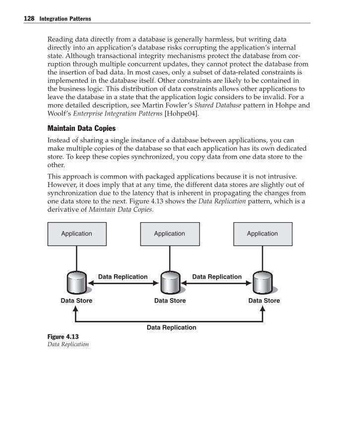
Integration Patterns128
Reading data directly from a database is generally harmless, but writing datadirectly into an application’s database risks corrupting the application’s internalstate. Although transactional integrity mechanisms protect the database from cor-ruption through multiple concurrent updates, they cannot protect the database fromthe insertion of bad data. In most cases, only a subset of data-related constraints isimplemented in the database itself. Other constraints are likely to be contained inthe business logic. This distribution of data constraints allows other applications toleave the database in a state that the application logic considers to be invalid. For amore detailed description, see Martin Fowler’s Shared Database pattern in Hohpe andWoolf’s Enterprise Integration Patterns [Hohpe04].
Maintain Data CopiesInstead of sharing a single instance of a database between applications, you canmake multiple copies of the database so that each application has its own dedicatedstore. To keep these copies synchronized, you copy data from one data store to theother.
This approach is common with packaged applications because it is not intrusive.However, it does imply that at any time, the different data stores are slightly out ofsynchronization due to the latency that is inherent in propagating the changes fromone data store to the next. Figure 4.13 shows the Data Replication pattern, which is aderivative of Maintain Data Copies.
Data Replication
Data Replication Data Replication
Application
Data Store
Application
Data Store
Application
Data Store
Figure 4.13Data Replication

Chapter 4: System Connections 129
The mechanisms involved in maintaining these copies are complex. Data Patternsdiscusses these mechanisms in a cluster of 12 data movement patterns [Teale03] thatuse Maintain Data Copies as a root pattern. The other patterns in the guide includethe following:● Move Copy of Data● Data Replication● Master-Master Replication● Master-Slave Replication● Master-Master Row-Level Synchronization● Master-Slave Snapshot Replication● Capture Transaction Details● Master-Slave Transactional Incremental Replication● Implementing Master-Master Row Level Synchronization Using SQL Server● Implementing Master-Slave Snapshot Replication Using SQL Server● Master-Slave Cascading Replication
For more details about these patterns, see Data Patterns on MSDN (http://msdn.microsoft.com/architecture/patterns/default.aspx?pull=/library/en-us/dnpatterns/html/Dp.asp).
File Transfer
In the File Transfer pattern, one application produces a file and transfers it so thatother applications can consume it. Because files are a universal unit of storage for allenterprise operating systems, this method is often simple to implement. The disad-vantage of this method is that two applications can lose synchronization with eachother because each one is changing the file independently. For more information, seeMartin Fowler’s File Transfer pattern [Hohpe04].
Choosing Between AlternativesThere are many factors to consider when you choose the kind of data integrationthat is best for your particular requirements. Some of those factors include:● Tolerance for data that is not current (stale data)● Performance● Complexity● Platform infrastructure and tool support

Integration Patterns130
After you pull data from a transactional system, the data is effectively stale. Whenyou attempt to modify the data, you encounter potential contention and conflictresolution logic. If your conflict resolution logic is simple, and if you can accommo-date relatively long time intervals with stale data, File Transfer may be the best wayto integrate data.
If your conflict resolution logic is more complex, and if you have less tolerance forstale data, consider Shared Database or Maintain Data Copies. Before deciding on oneor the other, consider your performance needs.
If your applications and databases are located in the same data center, then SharedDatabase enables you to use transaction managers to enforce data consistency. Usingtransaction managers to enforce data consistency limits stale data. However, if youhave too many applications accessing the same data, the database may become aperformance bottleneck for your system.
Maintaining multiple copies of the same data reduces the performance bottleneckof a single database, but it creates stale data between synchronizations. Also, if yourapplication is geographically distributed, sharing one single database creates exces-sive network latency and affects performance. Maintain Data Copies also presents itsown operations challenges. However, you can reduce the effort associated withmaintaining multiple copies by using the synchronization and replication capabili-ties that are built into many DBMSs.
As you can see, each form of data integration has advantages and disadvantages.Choosing the right kind of data integration depends on the factors that are mostimportant to your organization and on achieving the right balance among thetradeoffs.
BenefitsRegardless of the type of data integration you choose, the benefits are as follows:● Nonintrusive. Most databases support transactional multiuser access, ensuring
that one user’s transaction does not affect another user’s transaction. This isaccomplished by using the Isolation property of the Atomicity, Consistency,Isolation, and Durability (ACID) properties set. In addition, many applicationspermit you to produce and consume files for the purpose of data exchange. Thismakes Data Integration a natural choice for packaged applications that are diffi-cult to modify.
● High bandwidth. Direct database connections are designed to handle largevolumes of data. Likewise, reading files is a very efficient operation. High band-width can be very useful if the integration needs to access multiple entities at thesame time. For example, high bandwidth is useful when you want to createsummary reports or to replicate information to a data warehouse.
Chapter 4: System Connections 131
● Access to raw data. In most cases, data that is presented to an end user is trans-formed for the specific purpose of user display. For example, code values may betranslated into display names for ease of use. In many integration scenarios,access to the internal code values is more useful because the codes tend to morestable than the display values, especially in situations where the software islocalized. Also, the data store usually contains internal keys that uniquely iden-tify entities. These keys are critical for robust integration, but they often are notaccessible from the business or user interface layers of an application.
● Metadata. Metadata is data that describes data. If the solution that you use fordata integration connects to a commercial database, metadata is usually availablethrough the same access mechanisms that are used to access application data. Themetadata describes the names of data elements, their type, and the relationshipsbetween entities. Access to this information can greatly simplify the transforma-tion from one application’s data format to another.
● Good tool support. Most business applications need access to databases. As aresult, many development and debugging tools are available to aid in connectingto a remote database. Almost every integration vendor provides a databaseadapter component that simplifies the conversion of data into messages. Also,Extract, Transform, and Load (ETL) tools allow the manipulation of larger sets ofdata and simplify the replication from one schema to another. If straight datareplication is required, many database vendors integrate replication tools as partof their software platform.
LiabilitiesRegardless of the type of data integration you choose, the liabilities are asfollows:● Unpublished schemas. Most packaged applications consider the database chema
to be unpublished. This means that the software vendor reserves the right tomake changes to the schema at will. A solution based on Data Integration is likelyto be affected by these changes, making the integration solution unreliable. Also,many software vendors do not document their database schemas for packagedapplications, which can make working with a large physical schema difficult.

Integration Patterns132
● Bypassed business logic. Because data integration accesses the application datastore directly, it bypasses most of the business logic and validation rules incorpo-rated into the application logic. This means that direct updates to an application’sdatabase can corrupt the application’s integrity and cause the application tomalfunction. Even though databases enforce simple constraints such as unique-ness or foreign key relationships, it is usually very inefficient to implement allapplication-related rules and constraints inside the database. Therefore, thedatabase may consider updates as valid even though they violate business rulesthat are encoded in the application logic. Use Functional Integration instead ofData Integration if you need the target application to enforce complex businessrules.
● No encapsulation. Accessing an application’s data directly provides the advan-tage of immediate access to raw data. However, the disadvantage is that there islittle or no encapsulation of the application’s functionality. The data that isextracted is represented in the format of an application-internal physical databaseschema. This data very likely has to be transformed before other applications canuse it. These transformations can become very complex because they often haveto reconcile structural or semantic differences between applications. In extremescenarios, the data store may contain information in a format that cannot be usedby other systems. For example, the data store might contain byte streams repre-senting serialized business objects that cannot be used by other systems.
● Simplistic semantics. As the name suggests, Data Integration enables the integra-tion of data only. For example, it enables the integration of data contained inentities such as “Customer XYZ’s Address.” It is not well-suited for richer com-mand or event semantics such as “Customer XYZ Moved” or “Place Order.”Instead, use Functional Integration for these types of integration.
● Different storage paradigms. Most data stores use a representation that is differ-ent from the underlying programming model of the application layer. For ex-ample, both relational databases and flat-file formats usually represent entitiesand their relationships in a very different way from an object-oriented applica-tion. The difference in representation requires a translation between the twoparadigms.
● Semantic dissonance. Semantic dissonance is a common problem in integration.Even though you can easily resolve syntactic differences between systems,resolving semantic differences can be much more difficult. For example, althoughit is easy to convert a number into a string to resolve a syntactic difference, it ismore difficult to resolve semantic differences between two systems that haveslightly different meanings for the Time, Customer, and Region entities. Eventhough two databases might contain a Customer entity, the semantic context ofboth entities might be dramatically different.

Chapter 4: System Connections 133
Testing ConsiderationsTesting data integration solutions can be difficult for a number of reasons, includingthe following:● The direct access to the data source and destination does not allow isolation of a
specific function. For example, using a test stub or mock object does not allowisolation of a specific function. If the data exchange uses a file to transfer data,you can use test files to test the data insertion.
● Inserting data directly into the target database bypasses all or most businesslogic. Therefore, testing the insert itself may not be very meaningful because it islikely to succeed. Even if the data is inserted successfully into the database, thedata may violate another application’s business logic. As a result, the completeapplication may have to be regression tested after you insert data directly into theapplication data store.
● Because Data Integration puts few constraints on the data to be inserted into anapplication’s data store, a large data set may be required to provide appropriatecoverage of all test cases.
Security ConsiderationsData Integration presents potential security issues that are worth considering:● Coarse-grained security. Because Data Integration bypasses the application logic,
it also bypasses any security rules that are enforced by the application logic.Many databases manage access privileges at the table level. At the table level, auser either has access to the Customer table or the user does not have access.Most applications enforce security at an object level. At the object level, a specificuser has access only to those customer records that are associated with the user.
● Privacy policies may not be enforced. Many corporate databases are subject toprivacy policies that are based on corporate or legal guidelines. Directly accessingthese data stores may be in violation of these policies because it is difficult tocontrol the ways the retrieved data may be used. In comparison, FunctionalIntegration can offer restricted access to sensitive data to only allow queries thatdo not expose individual data. For example, a functional interface may allow theuser to query the average compensation in a specific region but not individualcompensation.
● Data may be encrypted. Data inside the database may be encrypted so that it isnot accessible for data integration unless the integration solution obtains the keyto decrypt the data. Providing the key to the data integration solution couldpresent a security risk unless the key is properly protected.

Integration Patterns134
Related PatternsFor more information, see the following related patterns:● Functional Integration. Data Integration is used to extract data from or insert data
into an existing application. If direct access to the data source must be avoided,use Functional Integration instead. Functional Integration interfaces with anapplication’s business logic.
● Data Consistency Integration [Ruh01]. In cases where inserting data into an appli-cation is tied to specific business rules and validations, straight data integrationmight not be the best solution because the business logic has to be re-created forthe data insert operation. In these cases, consider using Functional Integration toachieve data consistency.
Acknowledgments[Britton01] Britton, Chris. IT Architectures and Middleware – Strategies for BuildingLarge, Integrated Systems. Addison-Wesley, 2001.
[Hohpe04] Hohpe, Gregor, and Bobby Woolf. Enterprise Integration Patterns: Design-ing, Building, and Deploying Messaging Solutions. Addison-Wesley, 2004.
[Ruh01] Ruh, William. Enterprise Application Integration. A Wiley Tech Brief. Wiley,2001.
[Teale03] Teale, Philip; Christopher Etz, Michael Kiel, and Carsten Zeitz. “DataPatterns.” .NET Architecture Center. June 2003. Available at:http://msdn.microsoft.com/architecture/patterns/default.aspx.

Chapter 4: System Connections 135
Functional Integration
ContextEnterprise information systems contain a variety of applications that provide levelsof interaction that range from simple to complex. The functions that are included inthese systems offer a variety of capabilities and levels of access, from undocumentedfunctions and silo applications to fully developed composite applications. In addi-tion, the mechanism for invoking a function differs from one system to another.
ProblemHow do you integrate information systems that were not designed to worktogether?
ForcesTo correctly solve this problem, you need to consider the following forces:● Most enterprises contain multiple systems that were never designed to work
together. The business units that fund these information systems are primarilyconcerned with functional requirements rather than technical architectures.Because information systems vary greatly in terms of technical architecture,enterprises often have a mix of systems, and these systems have incompatiblearchitectures.
● Many applications are organized into three logical layers: presentation, businesslogic, and data.
● Most commercial business applications developed in the last decade providestable documented programming interfaces to allow access to the businessfunctionality that is incorporated in the application. Software vendors providethese APIs specifically to support integration with external software.
● The functional interfaces provided by an application typically abstract from theunderlying data representations so that they are more stable than the internalrepresentations. For example, while a database schema might change in a newversion of the software, the vendors keep the public APIs compatible with theprevious version so that external applications accessing the API do not break.
● Accessing a function that resides in another application provides a naturalextension of the application programming model that developers are used to. Thesemantics of accessing an external function that resides in another application aresimilar to making a local method call. This allows for natural integration withexisting applications.
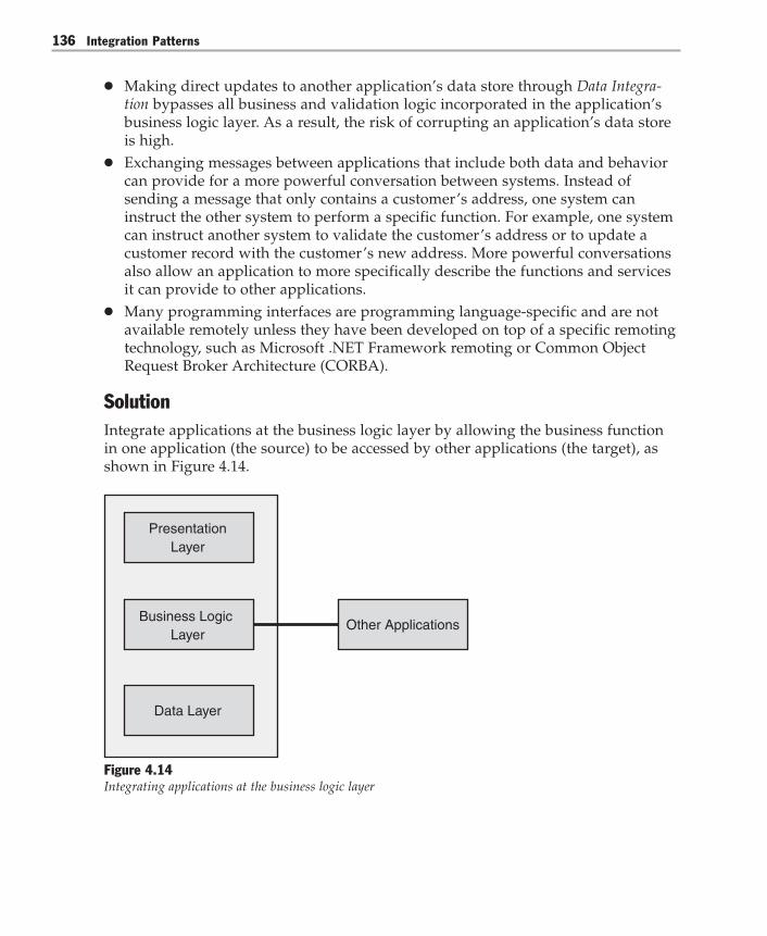
Integration Patterns136
● Making direct updates to another application’s data store through Data Integra-tion bypasses all business and validation logic incorporated in the application’sbusiness logic layer. As a result, the risk of corrupting an application’s data storeis high.
● Exchanging messages between applications that include both data and behaviorcan provide for a more powerful conversation between systems. Instead ofsending a message that only contains a customer’s address, one system caninstruct the other system to perform a specific function. For example, one systemcan instruct another system to validate the customer’s address or to update acustomer record with the customer’s new address. More powerful conversationsalso allow an application to more specifically describe the functions and servicesit can provide to other applications.
● Many programming interfaces are programming language-specific and are notavailable remotely unless they have been developed on top of a specific remotingtechnology, such as Microsoft .NET Framework remoting or Common ObjectRequest Broker Architecture (CORBA).
SolutionIntegrate applications at the business logic layer by allowing the business functionin one application (the source) to be accessed by other applications (the target), asshown in Figure 4.14.
Data Layer
PresentationLayer
Other ApplicationsBusiness Logic
Layer
Figure 4.14Integrating applications at the business logic layer

Chapter 4: System Connections 137
For an external application to integrate with the source application through Func-tional Integration, the following two conditions must be met:● The business function that you want must be available inside the source
application’s business logic.● The API of the source application must be accessible remotely.
If the desired business function is not available, you have to modify the sourceapplication to make the function available. If modifying the source application is notfeasible, you should add the new function outside the source application and thencommunicate with the application through another form of integration, such as DataIntegration or Presentation Integration. This approach has fewer side effects and isgenerally available for most types of applications.
Many applications only expose their business functions as a local API that is depen-dent on a specific programming language such as C++ or C#. In those cases, a localadapter or middleware interface has to be created that translates incoming messagesfrom other applications into local API calls. Likewise, results from API calls aretranslated back into messages. In most cases, such an adapter can be generic enoughto support a variety of different functions without having to be modified for eachindividual function that you want to make available externally.
Functional Integration is very versatile because many different operations can beperformed though an API. A functional interface can retrieve data, update dataentities (change an address), or perform business functions (validate a credit card).In fact, one common use of Functional Integration is to ensure data consistencybetween applications [Ruh01].
Functional Integration is based on the interaction between the components that aredescribed in Table 4.2.
Table 4.2: Functional Integration Components
Components Responsibilities Collaborators
Business logic Executes local business functions Middleware interface
Middleware interface – Converts incoming messages into method Business logic andinvocations of functions that reside in the remote applicationbusiness logic– Converts return data back into messagesthat can be transported across the network
Remote application Consumes functions that reside in the Middleware interfaceapplication

Integration Patterns138
Resulting ContextAfter you decide to use Functional Integration, you must choose a particular kind ofintegration that is appropriate for your situation. Your choices are summarized bythe following patterns:● Distributed Object Integration● Message-Oriented Middleware Integration● Service-Oriented Integration (through XML-based Web services)
Distributed Object IntegrationDistributed Object Integration is also known as instance-based collaboration because itextends the model of object-oriented computing to distributed solutions. Objectsinside one application interact with objects in another remote application in thesame way that they would interact locally with another object. This implies that theinteraction occurs with a specific object instance and that the client application oftenmanages the lifetime of the object it is accessing. This type of interaction usuallyseems natural to application developers, but it can result in a complex and tightly-coupled interaction model between the components. This tight coupling is not aproblem as long as the components are part of a single distributed application.However, it is generally not a good choice when integrating multiple stand-aloneapplications.
Great examples of distributed component middleware are technologies such as .NETremoting, COM+, or CORBA. For more information, see the Remote Procedure Invoca-tion pattern [Hohpe04] or the “Distributed Systems” chapter in Enterprise SolutionPatterns Using Microsoft .NET [Trowbridge03].
Message-Oriented Middleware IntegrationMessage-Oriented Middleware Integration connects systems by using asynchronousmessage queues that are based on proprietary message-oriented middleware. Theconnected systems then communicate by using messages that contain small packetsof data. Because the communication is asynchronous and durable, there is littlechance of the messages being lost during network or system failure.
To share request/response type functionality, the consuming system must create arequest message and send it by way of the message queue to the system that pro-vides the functionality. The provider then takes the message from the queue, inter-prets it as a request, and processes it. Upon completion, the provider creates aresponse message and sends it back to the functional consumer by way of themessage queue. Of course, not all functionality is shared by using a request/re-sponse style collaboration, but similar principles apply. For more information, seethe Messaging pattern [Hohpe04].

Chapter 4: System Connections 139
Service-Oriented IntegrationService-Oriented Integration connects systems by enabling them to consume andprovide XML-based Web services. The interfaces to these systems are describedthrough Web Services Definition Language (WDSL) contracts. Systems interact witheach other by using SOAP messages. SOAP messages are usually conveyed throughHTTP by using XML serialization.
Note: The term service is used in many different ways in the context of software engineering. Itis also used in at least seven levels of scope: operating system, process, object, distributedobject, proprietary message-oriented middleware, logical, and XML Web services. This guideuses the term service to mean XML Web services unless indicated otherwise.
A Service Interface [Trowbridge03] exposes functionality as a Web service, and, aService Gateway encapsulates the logic necessary to consume services (seeFigure 4.15).
Service Gateway Service Interface Service Implementation
Service Provider ApplicationService Consumer
Figure 4.15Using a service gateway and service interface to connect a Web service consumer and provider
Using Service-Oriented Integration increases interoperability by using XML and XMLSchema as the basis of message exchange and by using SOAP as an extensiblemessaging framework. XML Schema provides for a type system that is portablebetween disparate technical architectures. In contrast, SOAP can be bound to anumber of different transport mechanisms. For more information, see Service-Oriented Integration.
Choosing Between AlternativesThere are many factors to consider when choosing the kind of Functional Integrationthat is best for your particular requirements. Some of these factors include:● Reliability and latency of the network between endpoints● Interfaces exposed by your current systems● Need for interoperability between disparate technical architectures● Performance
Integration Patterns140
● Fragility, if incompatible updates are introduced to any participant● Expertise of the technical team● Existing infrastructure
Choosing Distributed Objects
If your team is proficient with object-oriented development and if you use a plat-form infrastructure that offers a Broker such as .NET Framework remoting, Distrib-uted-Object Integration can be fairly simple to implement. Although the remoteinterface is almost as easy to manipulate as the local interface, you must alwaysconsider network latency, network failure, and distributed systems failures. Youmust develop a significant amount of error detection and correction logic to antici-pate these impacts. With high-latency network round trips, you want to avoid alarge number of fine-grained method invocations. Therefore, use Remote Facade[Fowler03] and Data Transfer Object [Trowbridge03] to optimize call granularity andpayload size.
This kind of integration works best when the systems that you want to connect arelocated in the same data center and when those systems have fairly reliable andhigh-speed connections. This kind of integration does not work well across slow andunreliable connections, including any connection that uses the Internet. This kind ofintegration is fragile if incompatible updates are introduced to any of the partici-pants. Of course, if the target system you want to integrate with only exposes object-based APIs, you must use this method or an adapter to connect.
Choosing Message-Oriented Middleware Integration
Message-Oriented Middleware Integration is an excellent choice when systems are notreliably connected because there is the potential for network failure or distributedsystems failure. Because Message-Oriented Middleware Integration works by placingmessages asynchronously into a durable queue, there is little chance that the mes-sages could be lost during a system or network failure. In addition, using asynchro-nous communication decouples the sender from the receiver. The application thatsends the messages will continue to function even if the receiver fails, and the failedmessage receiver will continue processing messages from the queue after the re-ceiver is restored.
The sender and the receivers are also decoupled from each other because they use acommon message format. This makes it easier to separate the message from the set ofintended receivers in the enterprise. After a message is sent from a source, you candesign an integration network that uses the Message Broker pattern, the Message Buspattern, the Publish/Subscribe pattern, or a host of other message receivers withoutmodifying the original message sender. This allows the source, distribution, andconsumption of the message to vary independently, thus improving flexibility.

Chapter 4: System Connections 141
Of course, there are tradeoffs involved with using Message-Oriented Middleware.Although the programming model is fairly simple for Distributed-Object Integration,the programming model becomes much more complex for Message-OrientedMiddleware. Messages arriving at endpoints become events; therefore, the program-ming model is event driven. In addition, these events arrive across networks thatmay be unreliable and that do not have implicit correlation between them. The orderof message arrival is not necessarily guaranteed and there may be duplicate mes-sages. Sometimes, processing duplicate messages (also known as idempotent mes-sages) does not adversely affect your system. Other times, processing duplicatemessages is a serious flaw, for example, when you are transferring money. Thesecurity context of the message must be established, policies must be applied, andtrust boundaries must be established. Your particular requirements must anticipateand justify this additional complexity. In addition, using proprietary message-oriented integration binds you to a particular message-oriented middleware imple-mentation. It must be installed on the endpoint you want to communicate with,which may not always be the case inside your enterprise or between tradingpartners.
Service-Oriented Integration
Most enterprises have heterogeneous technical architectures and want to takeadvantage of system-based collaboration over the Internet. The most competitiveenterprises want flexible and automated business processes that may require tech-nology independence. All of these factors contribute to an urgent requirement forinteroperability between different technical architectures. The best way to designfor interoperability is by using Service-Oriented Integration.
Like Message-Oriented Middleware Integration, Service-Oriented Integration uses mes-sages to communicate between senders and receivers. Unlike Message-OrientedMiddleware, Service-Oriented Integration uses XML Schema and SOAP to transportand resolve messages. These two standards provide a portable type system and anextensible messaging framework that is not coupled to any proprietary implementa-tion or transport. In addition, Service-Oriented Integration recommends the WebServices Integration (WS-I) Basic Profile to ensure interoperability between end-points.
Service-Oriented Integration enables interoperability and allows you to send bothsynchronous and asynchronous messages (for more information, see the Service-Oriented Integration pattern). As a result, you can have the same kind of complexprogramming model as Message-Oriented Middleware. In addition, you have thecomplexity of a new and still emerging set of standards to understand and complywith. Therefore, make sure your requirements justify this level of complexity.

Integration Patterns142
After you build these interoperable systems, there is one more tradeoff to consider:performance. Using XML incurs the cost of serializing, deserializing, and parsingXML documents. In addition, XML documents are often much larger than theirbinary equivalents because they contain metadata. This can increase the size of thepayload that must be processed during message exchanges. However, becauseprocessing power is relatively inexpensive and because processors get faster everyyear, the issue of payload size can be addressed though hardware. Also, you canselectively trade interoperability for performance by using binary encoding insideyour SOAP message as needed. Finally, given the support of major vendors, it islikely that new platform infrastructure will evolve in a way that will optimize Webservices – based performance.
Combining Distributed Objects, Message-Oriented Middleware, and Services
It is likely you will use some combination of all three types of integration in yourenterprise. Start by identifying services at a level of granularity that is meaningfulto the business, such as steps within a business process. This will help you defineservice boundaries where interoperability is important. For interactions across theseboundaries, use Service-Oriented Integration. For an example of service identification,see Chapter 9, “Integration Examples.” To implement a service within these bound-aries, you may want to use Distributed-Object Integration, Message-OrientedMiddleware Integration, or Service-Oriented Integration. If you need to do two-phasecommits across distributed databases, using Distributed-Object Integration permitsyou to take advantage of platform infrastructure that supports two-phase commitsacross distributed databases. Just ensure that you keep these transactions insideyour service boundaries.
Any time you connect with systems and networks that you consider to be unreliable,consider using Message-Oriented Middleware to provide a durable buffer betweenconnected systems. Using messages as your means of communication, eitherthrough Message-Oriented Middleware or Service-Oriented Integration, permits you toconstruct more advanced integration architectures that use Message Broker andMessage Bus to communicate. As needed, you can always connect these integrationarchitectures by using object-based APIs as described by the Adapter pattern[Gamma95].
Regardless of the kind of Functional Integration you use, you will encounter thefollowing benefits and liabilities.
Benefits● Flexibility. Functional Integration is very flexible. The abstraction, in the form of a
function call, permits many different types of interchanges, such as data replica-tion, shared business functions, or business process integration. This also impliesthat a generic mechanism for Functional Integration can be used in many differentintegration scenarios.

Chapter 4: System Connections 143
● Encapsulation. A functional interface provides an abstraction from anapplication’s internal workings. This isolates users of the programming interfacefrom variations in the application’s internal workings or data representations.
● Robust. Executing a function through an application’s business logic layerensures that only well-defined functions can be executed. It also ensures that allvalidations built into the application logic are executed. This ensures that otherapplications cannot perform invalid functions or corrupt the application’s inter-nal state.
● Familiar programming model. Functional Integration provides a programmingmodel that is more aligned with widespread application programming models.Functional Integration is therefore familiar to most application developers. Otherstyles of integration, such as Data Integration or Presentation Integration, requiredevelopers to learn a new style of development.
Liabilities● Tighter coupling. One application that sends a command directly to another
application results in tighter coupling compared to publishing data to a commonMessage Bus because the requesting application requires information about thelocation of the application that is providing the service. However, inserting aMessage Broker can alleviate this type of coupling.
● Requires business layer to be exposed. Naturally, Functional Integration is lim-ited to scenarios where the affected applications expose a suitable functionalinterface. This is the case for most contemporary business applications, but it maynot be true for older monolithic applications or for Web applications hosted byexternal entities. In those cases, Presentation Integration may be the only option.
● Limited to available functions. In most cases, Functional Integration is limited tothe functions that are already implemented in the application’s business logic.Extending the application’s logic with new functions usually involves significantdevelopment and may outweigh the other benefits of Functional Integration. Insuch cases, implementing the new function externally might be a more efficientapproach.
● Inefficient with large datasets. Existing functional interfaces are generallydesigned to execute individual functions. This typically makes them inefficientfor the transmission of large datasets because many individual requests must bemade.
Integration Patterns144
● Programming-language specific. Many functional interfaces are tied to a specificprogramming language or technology because the stronger semantics of theconversation require a more detailed contract that includes the representation ofmethod names, complex data structures, return values, exceptions, and otherelements.
Testing ConsiderationsFunctional Integration is easier to test than other integration approaches for thefollowing reasons:● The additional abstraction provided by the separation of the exposed functional
interface and the internal execution of the function permits the creation of mockobjects and test stubs. These constructs work with the external applications in thesame way the full application does because they implement the same interface.However, the test stub or mock object usually does not perform actual businessfunctions that may be slow or that may require many external resources. Instead,the stub fabricates response data, or it logs data into a logging mechanism thatcan be monitored by the test tools.
● Because Functional Integration is based on the same programming model as theapplication itself, tests of the integration are easier to tie to the testing of theapplication itself. This type of testing is also generally well-supported by testtools such as NUnit that target application testing.
However, you must consider the following considerations. Your ability to test dependson how well the functional interface of the existing application is structured. If theinterface exposes functions that are well-defined and that are free of side effects free,testing should be relatively easy. If the functional interface consists of a blur of poorlydefined functions that are full of side effects, then testing will be difficult.
Security ConsiderationsThe richer semantics of Functional Integration allow for a more finely grained securitymodel. Many applications enforce security rules based on user identity, and theycontrol permissions on an object level. For example, a user is only allowed to accessthe accounts that belong to that user and to access related accounts. This type ofpermission checking is typically not available with Data Integration.
The disadvantage of this more complex security model is that the integration solu-tion has to acquire the proper user credentials to access data or to invoke functions.Because other applications are generally unaware of the security context used inanother application, the security context has to be established by the middleware.You can establish the security context either by using a fixed user or by using anexplicit translation of security contexts between applications.

Chapter 4: System Connections 145
Acknowledgments[Hohpe04] Hohpe, Gregor, and Bobby Woolf, Enterprise Integration Patterns: Design-ing, Building, and Deploying Messaging Solutions. Addison-Wesley, 2004.
[Linthicum04] Linthicum, David. Next Generation Application Integration. Addison-Wesley, 2003.
[Ruh01] Ruh, William. Enterprise Application Integration. A Wiley Tech Brief. Wiley,2001.
[Trowbridge03] Trowbridge, David; Dave Mancini, Dave Quick, Gregor Hohpe,James Newkirk, and David Lavigne. Enterprise Solution Patterns Using Microsoft.NET. Microsoft Press, 2003. Also available on the MSDN Architecture Center at:http://msdn.microsoft.com/architecture/patterns/default.aspx?pull=/library/en-us/dnpatterns/html/Esp.asp
[W3C04] “Web Services Architecture W3C Working Draft 11 February 2004.” Avail-able on the W3C Web site at: http://www.w3.org/TR/2004/NOTE-ws-arch-20040211/

Integration Patterns146
Service-Oriented Integration
ContextYou’ve decided to use the Functional Integration pattern to integrate informationsystems that were not designed to work together. You need interoperability amongsystems built with different technical architectures. In addition, the systems that youwant to integrate may not be reliably connected.
ProblemHow do you integrate applications at the business logic layer?
ForcesIntegrating systems at the business logic layer involves balancing the followingforces:● Machine boundaries are important. The idea that you can take a local object
interface and extend it across machine boundaries to create location transparencyis flawed. Although it is true that both the remote objects and the local objectshave the same interface from the perspective of the calling process, the behaviorof the called interface is quite different depending on location. From the clientperspective, a remote implementation of the interface is subject to networklatency, network failure, and distributed system failures that do not exist withlocal implementations. A significant amount of error detection and correctionlogic must be written to anticipate the impacts of using remote object interfaces.
● Coupling affects interoperability. Integrating at the logical business layerinvolves sharing functionality. Sharing functionality implies some level of cou-pling between the consumer and the provider of the functionality. There aremany forms of coupling. These forms of coupling include the following:● Temporal coupling. Temporal coupling occurs during the request for func-
tionality. If the request is synchronous, the calling system must wait for theprovider to finish processing the request before it can continue. If the requestis asynchronous, the calling system can continue processing after it makes therequest while the providing system independently continues to process therequest. In terms of time, the asynchronous call is more loosely coupled thanthe synchronous call.
Chapter 4: System Connections 147
● Type-system coupling. Type-system coupling occurs when a process mustassociate the name of a type with its binary representation on the host com-puter. This association may be as simple as an integer, meaning a big-endian4-byte primitive on one computer and a 2-byte little-endian primitive onanother. Of course, user-defined types such as a customer object become muchmore complex. When two systems interoperate, they must share a commontype representation; in this sense they are coupled together. Most implementa-tion platforms do not share the same type representation.
● Dependency coupling. Dependency coupling occurs when one executabledepends on other executables to run. If the executable cannot resolve itsdependencies at run time, the executable fails. In this sense, the executable andits dependencies are coupled together.
To integrate disparate systems, you must resolve potential differences in typesystems and execution dependencies. You must also decide whether you want thecalling thread of execution to block when making a request to the provider.
● Coupling and Interface Definition Language. Even when the type system isdescribed using an Interface Definition Language (IDL), platform infrastructurecode must be installed on the host computer that interprets the IDL. For example,if you are using Common Object Request Broker Architecture (CORBA), infra-structure such as an Object Request Broker (ORB) must be installed on the hostcomputer for a system to resolve the CORBA IDL types. Two CORBA-basedsystems that are installed on different hardware platforms and operating systemscan interoperate, but they both remain coupled to the CORBA type specificationand binary mappings.
● Coupling and message-oriented middleware. Type-system coupling also occurswhen using proprietary message-oriented middleware. To resolve messageformats, each endpoint must contain an installation of the appropriate message-oriented middleware. Although a particular message-oriented-middlewareproduct may be ported to multiple platforms, any endpoint you want to commu-nicate with must also have the same message-oriented middleware productinstalled.
● Portable type system. Most enterprise systems can process XML. From theperspective of type-system coupling, the only primitive that must be agreed uponis a string. After the incoming byte stream is interpreted as a string buffer, thestring can be parsed according to XML specifications, including XML schema. Inturn, the schema provides a type system that is highly portable between dispar-ate hardware and operating systems.
● Contracts. Contracts have proven to be an excellent means of specifyingbehavior between a consumer and a provider of services.

Integration Patterns148
SolutionTo integrate applications at the business logic layer, enable systems to consume andprovide XML-based Web services. Use Web Services Description Language (WSDL)contracts to describe the interfaces to these systems. Ensure interoperability bymaking your implementation compliant with the Web Services family of specifica-tions (for example, the Web Services Security [WS-Security] specification). For moreinformation about the Web Services specifications, see “Specifications” in the WebServices Developer Center on MSDN (http://msdn.microsoft.com/webservices/under-standing/specs/default.aspx). Whenever possible, use the document message style andliteral serialization (see “Use Document/Literal SOAP Styles and Encoding” later inthis pattern).
Note: The term service is used in many different ways in the context of software engineering. Itis also used in at least seven levels of scope: operating system, process, object, distributedobject, proprietary message-oriented middleware, logical, and XML Web services. This guideuses the term service to mean XML Web services unless indicated otherwise.
To expose existing functionality as a Web service, use the Service Interface pattern[Trowbridge03]. To encapsulate the logic necessary to consume services, use theService Gateway pattern [Trowbridge03]. Figure 4.16 shows the design elementsinvolved in this interaction.
Service Gateway Service Interface Service Implementation
Service Provider ApplicationService Consumer
Figure 4.16Using Service Gateway and Service Interface to connect a Web service consumer and provider
In addition to following the Web Services specifications, you should also refer tothe Web Services Interoperability (WS-I) profiles when you design and build Webservices. For more information about WS-I, see the Web Services InteroperabilityOrganization Web site (http://www.ws-i.org). For guidance about how to build Webservices that are compliant with the WS-I basic profile, see Building Interoperable Webservices: WS-I Basic Profile 1.0 on MSDN (http://msdn.microsoft.com/library/default.asp?url=/library/en-us/dnsvcinter/html/wsi-bp_msdn_landingpage.asp).
Chapter 4: System Connections 149
Web ServicesWhat exactly is a Web service? According to the World Wide Web Consortium(W3C),
“a Web service is a software system designed to support interoperablemachine-to-machine interaction over a network. It has an interface describedin a machine-processable format (specifically WSDL). Other systems interact withthe Web service in a manner prescribed by its description using SOAP-messages,typically conveyed using HTTP with an XML serialization in conjunction withother Web-related standards.” [W3C04]
In terms of interaction, two systems use Web services to communicate when arequesting application creates an XML document in the form of a message and sendsit over the network to a provider of Web services. Optionally, the provider sends areply to the requester in the form of an XML document. Web services standardsspecify the interface that the message is sent to, the format of the message, themapping of the message contents to service implementations, the optional headers,and the means by which services can publish and discover other Web services.
Resolving the ForcesHow does using Web services to integrate systems resolve the forces mentionedearlier? First, basing your messages on XML and XML Schema definition language(XSD) results in a highly portable type system as explained earlier. A portable typesystem dramatically reduces type-system coupling. Type-system coupling is a majorimpediment to cross-platform integration. However, to take full advantage of thisportable type system, you must understand SOAP styles and encoding.
Use Document/Literal SOAP Styles and Encoding
The WSDL 1.1 specification identifies two message styles (document and RemoteProcedure Call [RPC]) and two means of serializing the message onto the transportmechanism (SOAP encoding and XML Schema). Choosing the right combinationof style and serialization have major impact on the interoperability of your Webservice.
The document message style indicates that the message body contains an XMLdocument. It is up to the service consumer and the service provider to agree on thedocument exchanged. The RPC style indicates that the message body will containan XML representation of an RPC.

Integration Patterns150
To serialize the message data, the XML Schema – based serialization simply usesthe definitions contained in the XML Schema specification. Because using XMLSchema results in a highly portable type system, the messages are highlyinteroperable. However, the SOAP-encoded serialization uses encoding rules thatrequire RPC-style communication. Since the details of RPC communication canvary significantly between implementations, the resulting messages are not aseasily interoperable.
As a result of these interoperability concerns, use document-style messages withliteral encoding (doc/literal) whenever possible. For more information about thistopic, see “Understanding Soap” on MSDN (http://msdn.microsoft.com/webservices/understanding/webservicebasics/default.aspx?pull=/library/en-us//dnsoap/html/understandsoap.asp).
Combine Synchronous and Asynchronous Behavior to Address Temporal Coupling
To address temporal coupling, it is possible to invoke Web services both synchro-nously and asynchronously. To understand how to do this in the context of Webservices, you must understand parts of the WSDL, SOAP, and Web Service Architec-ture specifications.
To abstract communication away from implementation notions such as synchronousand asynchronous calls, WSDL uses the concept of message exchange patterns(MEP) to describe generic patterns of message exchange between endpoints. Thereare four kinds of MEP described in WSDL 1.1, as shown in Table 4.3.
Table 4.3: Four Kinds of Message Exchange Patterns (MEP)
MEP name Description Type
Request-response The endpoint receives a message and then Synchronous*sends a correlated message.
One-way The endpoint receives a message. Asynchronous
Solicit-response The endpoint sends a message and then Synchronous*receives a correlated message.
Notification The endpoint sends a message. Asynchronous
* This MEP emulates synchronous behavior with HTTP POST/GET SOAP binding.
Chapter 4: System Connections 151
SOAP provides an extensible one-way messaging framework between sender andreceiver. To implement SOAP, however, you must bind it to a specific protocol.HTTP POST/GET is the most common protocol. Because HTTP is a synchronousprotocol, if you use the SOAP/HTTP binding, you get the synchronous/asynchro-nous behavior shown in Figure 4.17.
In cases where there are long-running transactions across enterprises, a Web serviceexchanges messages synchronously while the larger business process that it runswithin executes asynchronously. For example, consider the Global Bank scenario.
Global Bank’s Asynchronous Business Process
In the Execute Scheduled Payment use case (see Chapter 2 for more details), GlobalBank sends international payments through a Society for Worldwide InterbankFinancial Telecommunication (SWIFT) payment gateway by using Web services overthe Internet. The message sent is an XML document containing the informationnecessary for the payment gateway to electronically pay the payee identified in thedocument. This message is sent synchronously through HTTP, and the responseonly acknowledges a successful transmission. When the successful transmissionoccurs, the payment gateway processes the message, and the calling system does notwait for a response. After the payment gateway has finished processing the pay-ment, it sends another message to Global Bank confirming the payment status. Thismessage is a synchronous HTTP request/response, and the response informationonly acknowledges a successful message transmission.

Integration Patterns152
ExecutePayment
Ack [HTTP 200]
UpdatePaymentStatus
Ack [HTTP 200]
ExecutePayment
Ack [HTTP 200]
Global Bank PaymentSystem Web Service
PayeeSWIFT PaymentGateway Web Service
Figure 4.17SWIFT payment gateway combining synchronous exchanges to simulate asynchronous behavior
In the Execute Scheduled Payment use case, two synchronous message exchangesparticipate in an asynchronous business collaboration. This effectively decouples thesystems.

Chapter 4: System Connections 153
Recognize Explicit Boundaries
Because Web services pass documents instead of RPC calls, there is no attempt toconsider that the location of the service is transparent. Indeed, the boundary be-tween the two services is explicitly recognized. With explicit boundaries, the connec-tion is not treated as reliable and available, as it would be treated with DistributedObject Integration. You can use other patterns such as Server Clustering, Load-BalancedCluster, and Failover Cluster [Trowbridge03] to meet operational requirements whentraversing these boundaries.
Treat Services as Autonomous
When using services to integrate systems, you should consider two key elements:service interfaces and service implementations. Service interfaces describe thefunctionality, messages, and results that the consumers of the service can expect.Contracts provide these interfaces in the form of WSDL files. Service implementa-tions contain the software that implements the service and all its execution depen-dencies, with the possible exception of other services.
Collaborations through service interfaces facilitate a high degree of interoperabilityin your enterprise. The services should be capable of being independently versioned,managed, and deployed. As these services are deployed, all the appropriate execu-tion dependencies (except other services) should be deployed with the service andcontained within the service boundary.
ExampleFor detailed examples, see Implementing Service-Oriented Integration with ASP.NETand Implementing Service-Oriented Integration with BizTalk Server 2004.
Resulting ContextAs a result of implementing the Service-Oriented Integration pattern, the followingtenets apply [Box04]:● Boundaries are explicit. Crossing service boundaries can be costly. For example,
you may need to span geography, trust boundaries, or execution environments..You should therefore explicitly opt into service orientation by formally passingdefined messages between services. The explicit boundaries allow you to for-mally express implementation-independent interaction so that your interactionsdo not depend on the different platform, middleware, or coding language choicesused to implement other services.
Integration Patterns154
● Services are autonomous. There is no presiding authority in a service-orientedenvironment. Services are independently deployed, versioned, and managed. Thetopology in which a service executes evolves over time. The service should expectthat peer services will fail and that it will receive malformed or malicious mes-sages. The services should be built by using techniques such as redundancy andfailover so that the services do not fail.
● Services share schema and contract, not class. Services interact solely on theirexpression of structures through schemas and behaviors through contracts. Theservice’s contract describes the structure of messages and ordering constraintsover messages. The formality of the expression allows machine verification ofincoming messages. Machine verification of incoming messages allows you toprotect the service’s integrity. Contracts and schemas must remain stable overtime, so building them flexibly is important.
● Service compatibility is based on policy. Services express their capabilities andrequirements in terms of a machine readable policy expression. Policy assertionsare identified by a stable, globally unique name. Individual policy assertions areopaque to the system as a whole; services must simply be able to satisfy eachother’s policy requirements.
BenefitsThe key benefit of using Service-Oriented Integration is interoperability betweendisparate technical architectures. Interoperability at the level of technical architec-ture helps to decouple an enterprise’s business architecture from its informationtechnology. This decoupling gives an enterprise a great deal of flexibility in terms ofhow it implements specific business capabilities.
Although an enterprise contains processes, resources, goals, business rules, andrelationships [Eriksson00], it is the business processes that define how work actuallyis done. Technical architectures enable work to be done efficiently by incorporatingbusiness processes.
Without interoperable systems, the cost of process change is relatively high becauseit may involve crossing technology boundaries. When using interoperable systems,however, the cost of process change is dramatically lowered. This is especially truewhen services are designed at a level of granularity that is meaningful to the busi-ness, such as steps within a process. Businesses that have interoperable systems andthat use services that are relevant to business process are in a better position to senseand respond to market changes and opportunities. These businesses become moreagile as a result of creating interoperable systems and using services that are rel-evant to business practices.

Chapter 4: System Connections 155
LiabilitiesThe key liability of using Service-Oriented Integration is the performance cost ofserializing, deserializing, and parsing XML documents. In addition, XML documentsare much larger than their binary equivalents because they contain metadata. Thisincreases the size of the payload that must be processed during message exchange.
Security ConsiderationsSecurity is critical to services. Given its complex and technology-specific nature, youmust consider security individually for each implementation.
Related PatternsFor more information, see the following related patterns:● Implementing Service-Oriented Integration with ASP.NET.● Implementing Service-Oriented Integration with BizTalk Server 2004.● Broker [Buschmann96]. To discover and publish services, Web services use an
implementation of the Universal Description, Discovery, and Integration of WebServices (UDDI) specification. UDDI is an implementation of the Indirect Brokerpattern. The Indirect Broker is a specialized kind of Broker [Buschmann96]. IndirectBroker enables one endpoint to locate another. After the other endpoint is located,the two endpoints communicate directly with each other. In comparison, DirectBroker also helps make the initial connection, but it maintains central control overthe communication. For an example of a Direct Broker, see Message Broker.
● Service Gateway [Trowbridge03]. This pattern contains the code that implementsthe consumer portion of the contract into its own Service Gateway component.
● Service Interface [Trowbridge03]. This pattern designs an application as a collec-tion of software services. Each software service has a service interface that con-sumers of the application can interact through.
Acknowledgments[Box04] Box, Don. “Code Name Indigo: A Guide to Developing and Running Con-nected Systems with Indigo.” MSDN Magazine. January 2004. Available from theMSDN Windows Code-Named “Longhorn” Developer’s Center at:http://msdn.microsoft.com/longhorn/understanding/pillars/indigo/default.aspx?pull=/msdnmag/issues/04/01/Indigo/default.aspx.
[Buschmann96] Buschmann, Frank; Regine Meunier, Hans Rohnert, PeterSommerlad, and Michael Stal. Pattern-Oriented Software Architecture, Volume 1: ASystem of Patterns. John Wiley & Sons Ltd, 1996.

Integration Patterns156
[Erikkson00] Eriksson, Hans-Erik, and Magnus Penker. Business Modeling with UML:Business Patterns at Work. John Wiley & Sons, Inc., 2000.
[Newcomer02]. Newcomer, Eric. Understanding Web Services: XML, WSDL, SOAP, andUDDI. Addison-Wesley, 2002.
[Skonnard03-2] Skonnard, Aaron. “Understanding SOAP.” MSDN Web ServicesDeveloper Center, March 2003. Available at:http://msdn.microsoft.com/webservices/understanding/webservicebasics/default.aspx?pull=/library/en-us//dnsoap/html/understandsoap.asp.
[Trowbridge03] Trowbridge, David; Dave Mancini, Dave Quick, Gregor Hohpe,James Newkirk, and David Lavigne. Enterprise Solution Patterns Using Microsoft.NET. Microsoft Press, 2003. Also available on the MSDN Architecture Center at:http://msdn.microsoft.com/architecture/patterns/default.aspx?pull=/library/en-us/dnpatterns/html/Esp.asp.
[W3C04] “Web Services Architecture W3C Working Draft 11 February 2004.” Avail-able on the W3C Web site at:http://www.w3.org/TR/2004/NOTE-ws-arch-20040211/
[Wanagel03] Wanagel, Jonathan, et al. “Building Interoperable Web Services: WS-IBasic Profile 1.0.” MSDN Library, August 2003. Available at:http://msdn.microsoft.com/library/default.asp?url=/library/en-us/dnsvcinter/html/wsi-bp_msdn_landingpage.asp.
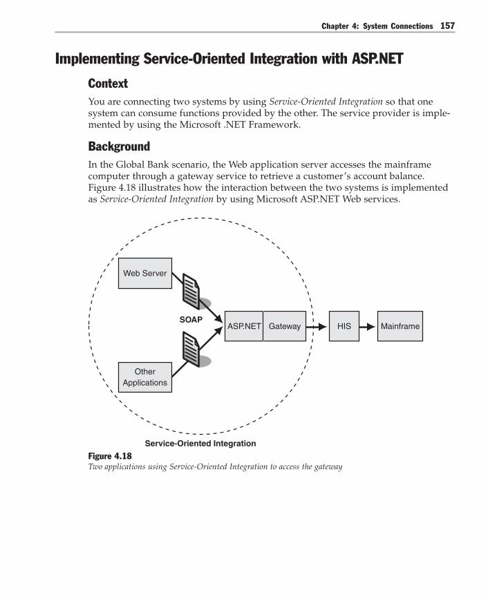
Chapter 4: System Connections 157
Implementing Service-Oriented Integration with ASP.NET
ContextYou are connecting two systems by using Service-Oriented Integration so that onesystem can consume functions provided by the other. The service provider is imple-mented by using the Microsoft .NET Framework.
BackgroundIn the Global Bank scenario, the Web application server accesses the mainframecomputer through a gateway service to retrieve a customer’s account balance.Figure 4.18 illustrates how the interaction between the two systems is implementedas Service-Oriented Integration by using Microsoft ASP.NET Web services.
Mainframe
OtherApplications
Service-Oriented Integration
GatewayASP.NET
Web Server
HISSOAP
Figure 4.18Two applications using Service-Oriented Integration to access the gateway

Integration Patterns158
This implementation describes how to expose functionality that resides on a main-frame computer as a Web service so that it can be accessed through Service-OrientedIntegration. The gateway is a custom C# application that connects to the bankingmainframe computer through Microsoft Host Integration Server (HIS). The main-frame computer manages the account balances for the customer accounts andprovides functions such account balance retrieval, account credits, and accountdebits.
Note: This implementation focuses on the interaction between the Web server and the Gatewaycomponent. For a more detailed description of the interaction between the Gateway and themainframe computer, see Implementing Gateway with Host Integration Server 2004.
The mainframe gateway exposes a number of different methods to get accountbalances, to credit and debit accounts, and to perform other functions. This imple-mentation describes only the use of the GetAccountInfo method to return the nameand balance of an account.
Implementation StrategyAs already mentioned, the strategy is to enable Service-Oriented Integration by expos-ing mainframe functionality as an ASP.NET Web service. Before discussing detailedsteps, it is helpful to review the concept of Service-Oriented Integration as well assome details about ASP.NET Web services.
Service-Oriented IntegrationService-Oriented Integration connects applications through the exchange of docu-ments, usually in the form of XML documents. Figure 4.19 shows Service-OrientedIntegration passing documents between a service consumer and a service provider.
DocumentExchange
Channel
ServiceConsumer
ServiceProvider
Figure 4.19Document exchange in Service-Oriented Integration

Chapter 4: System Connections 159
The document exchange in Figure 4.19 does not imply interaction with a specificinstance of a remote object. Instead, when the document is passed from the con-sumer to the provider, it triggers the execution of a specific function or service that isself-contained and stateless. This is an important difference between Service-OrientedIntegration and Distributed Object Integration (also known as instance-based integra-tion), which allows the client to manage the lifetime of a specific remote objectinstance.
The following example shows an XML document passed inside a SOAP envelope.
<?xml version="1.0" encoding="utf-8"?><soap:Envelope xmlns:xsi="http://www.w3.org/2001/XMLSchema-instance" xmlns:xsd="http://www.w3.org/2001/XMLSchema" xmlns:soap="http://schemas.xmlsoap.org/soap/envelope/"> <soap:Body> <GetAccountInfoRequest xmlns="http://msdn.microsoft.com/patterns/"> <AccountID xmlns="">12345678</AccountID> </GetAccountInfoRequest> </soap:Body></soap:Envelope>
ASP.NET Web ServicesWhen you use ASP.NET to implement a Web service, the function that processes theincoming document is implemented as a method of a .NET Framework class. The.NET Framework manages the instantiation of a specific instance of that class.
The .NET Framework does quite a bit of work behind the scenes when it receives anincoming SOAP request, as shown in Figure 4.20. Understanding the functions thatthe .NET Framework performs internally is not strictly necessary, but it is veryhelpful when designing ASP.NET Web services. It also gives you a good apprecia-tion of the amount of functionality that resides in the .NET Framework.
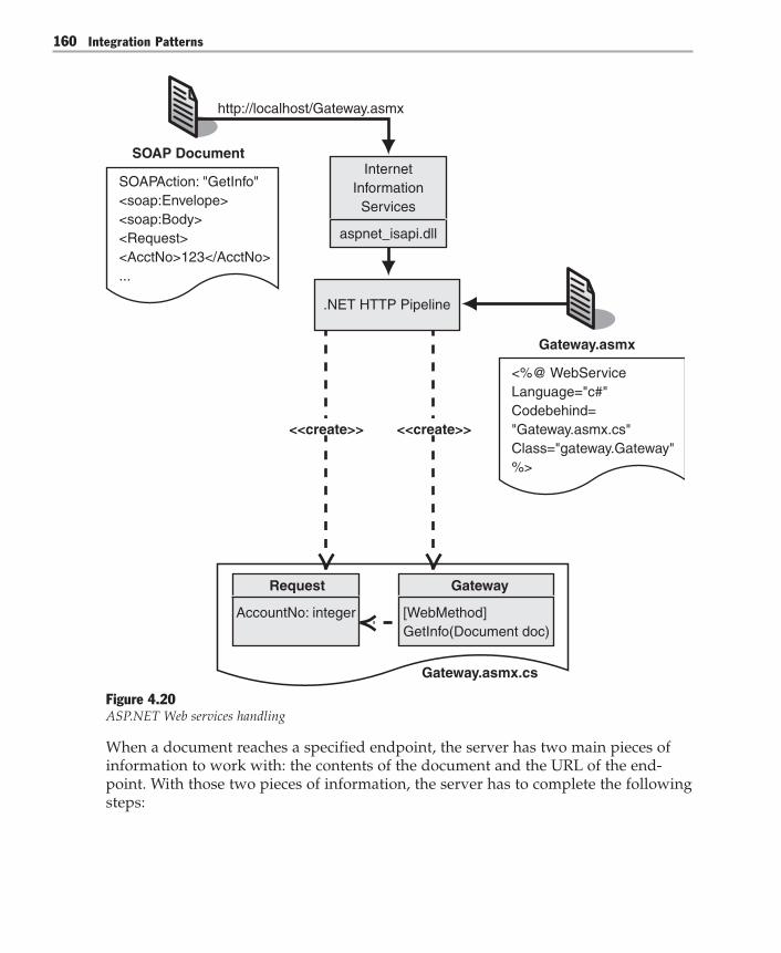
Integration Patterns160
<<create>>
SOAPAction: "GetInfo"<soap:Envelope><soap:Body><Request><AcctNo>123</AcctNo>...
<%@ WebServiceLanguage="c#"Codebehind= "Gateway.asmx.cs"Class="gateway.Gateway"%>
http://localhost/Gateway.asmx
.NET HTTP Pipeline
InternetInformation
Services
aspnet_isapi.dll
Request
AccountNo: integer
Gateway
Gateway.asmx.cs
[WebMethod]GetInfo(Document doc)
<<create>>
SOAP Document
Gateway.asmx
Figure 4.20ASP.NET Web services handling
When a document reaches a specified endpoint, the server has two main pieces ofinformation to work with: the contents of the document and the URL of the end-point. With those two pieces of information, the server has to complete the followingsteps:
Chapter 4: System Connections 161
1. Determine the .NET Framework class that should handle the request.2. Determine the method to invoke inside that class.3. Instantiate data transfer objects to pass data from the incoming document to the
method.4. Invoke the method.5. Return the results.
Internet Information Services (IIS) uses the file extension of the incoming URL tomap requests to the appropriate Internet Services API (ISAPI) handler. ASP.NETWeb services endpoints carry an .asmx extension in the URL. The .asmx extension inthe URL causes IIS to map the request to the standard .NET Framework HTTPpipeline. Based on default computer configuration settings, the .NET FrameworkHTTP pipeline hands control over to a WebServiceHandler. TheWebServiceHandler in turn determines the .NET Framework class that is associatedwith the URL by reading the .asmx file referenced by the URL. In Figure 4.21, theGateway.asmx file specifies the class Gateway as the class servicing requests. Thisclass is defined inside a code-behind page named Gateway.asmx.cs.
The Web service handler still has to determine the method to invoke for the incom-ing document. By default, it determines the method to invoke based on the value ofthe SOAPAction field that is part of the HTTP header. The following is a sample ofthat part of an HTTP header.
SOAPAction: "http://msdn.microsoft.com/patterns/GetAccountInfo"
After the Web service handler has determined the method to invoke, it parses theincoming XML document and creates an instance of the matching .NET Frameworkobjects to be passed to the method. This step is referred to as deserialization and isperformed by the .NET Framework XML Serializer. The method performing thefunction does not even have to know that the parameters were originally passed asan XML document wrapped inside a SOAP envelope. Lastly, the Web service han-dler creates an instance of the class that implements the service function and invokesthe appropriate method, passing instances of the applicable data transfer objects.
For a more detailed description of ASP.NET Web service internals, see “HowASP.NET Web Services Work” on MSDN (http://msdn.microsoft.com/library/default.asp?url=/library/en-us/dnwebsrv/html/howwebmeth.asp) [Skonnard03].

Integration Patterns162
Building an ASP.NET Web ServiceXML Web services expose the service contract to potential consumers as a WebServices Description Language (WSDL) document. To simplify development of Webservices, the .NET Framework offers a variety of capabilities, including the auto-matic generation of WSDL documents based on a service implementation. As aresult, you have a number of options when creating a new service interface:● Develop the code first. Write the service implementation code first, and then let
the .NET Framework create the WSDL document from the code.● Specify the XML schemas first. Develop message schemas as XML Schema
definition language (XSD) schemas first, generate code from the schemas, andthen let the .NET Framework create the WSDL document.
● Develop the WSDL first. Develop the WSDL definition first, and then let the.NET Framework generate skeleton code matching the definition.
Each approach has advantages and limitations. Generally, the choice is among theamount of control you need, the effort required, and the ease of integrating withother platforms.
Developing the Code First
The easiest way to expose code as a Web service is to label a .NET Frameworkclass with the [WebService] attribute and to label the affected method with a[WebMethod] attribute. The .NET Framework then takes care of all the details. Forexample, it generates the WSDL document to give potential clients a description ofthe service. To perform this conversion without any additional information, the.NET Framework derives the names of SOAP body elements from the name of themethod and its arguments. The advantage of this approach is clearly its simplicity.With two lines of extra “code,” a method can become a Web service that can beinvoked remotely. The limitation lies in the fact that the service interface exactlyresembles the code, including variable names. The .NET Framework allows you tooverride the default naming choices by specifying additional attributes, but thespecification for the service still resides in application code. This can be undesirable,for example, if an enterprise wants to keep a global repository of all message defini-tions independent of the platform that implements a particular service. Anotherpotential pitfall, however, is that this approach can generate a service that will notfunction properly. For example, if a method returns a non-serializable object, anyservice invocation will fail even though the code compiled without errors.

Chapter 4: System Connections 163
Specifying XML Schemas First
A Web services call typically requires two separate messages: a request message anda response message. These messages play roles similar to the roles played by theparameters and the return value of a regular method. Just as defining the signatureof a method is an important first step in the creation of a new method, defining therequest and return message formats is a logical first step in the creation of a Webservices interface. After the message format has been specified, it can be compiledinto a C# classes automatically without incurring additional effort. At run time, the.NET Framework still renders the WSDL document and eliminates the need forhand-coding.
XML Web services use XSD documents to define message formats. Defining thesedocuments by using a standard format such as XSD has advantages over generatingthem from the code. XSD documents are platform-independent and can be used todefine message formats independent of the technology implementing the service,whether it is the .NET Framework, the Java 2 Platform, Java 2 Enterprise Edition(J2EE), or any in a range of other technologies. This makes it feasible to keep a globalrepository of all message types in an enterprise. Creating XML schemas also givesthe interface designer exact control over the look of SOAP messages that are sent toand from a particular service.
Potential disadvantages of developing the XSD schemas first include the fact that anew specification language (XML Schema) and tool has to be used. However, manymodern development environments, including Microsoft Visual Studio .NET, in-clude powerful and easy-to-use XML Schema editors. Creating XSD documents firstalso requires additional development and build steps because the XSD documentfirst has to be converted into C# classes. This step has to be repeated whenever theXSD document changes, presenting the risk that the document and the implementa-tion of the service can get out of synchronization.
Developing WSDL First
The specification of a service contract depends on factors other than just the formatof inbound and outbound messages. For example, to be accessible, the service has tobe bound to a port that can be addressed by using a specified Uniform ResourceIdentifier (URI). A WSDL document specifies these additional contract terms, suchas ports and binding. Starting with the creation of a WSDL document ensures thatall details of the service contract (at least to the extent that they are supported byWSDL) can be specified directly and in a technology-neutral manner. The biggestdrawback of starting with a WSDL document is that the verboseness of WSDLmakes the manual creation tedious.

Integration Patterns164
Example: Building an ASP.NET Web Service to Access the MainframeGatewayAs described in the Global Bank scenario, the Web application server accesses themainframe computer through a gateway service to retrieve a customer’s accountbalance. This example creates an ASP.NET Web service that accesses the gateway tothe mainframe.
The ASP.NET page framework supports the development of both service providersand service consumers. This implementation begins with the design and develop-ment of the service provider. In the example, the mainframe gateway is the serviceprovider. Fortunately, most of the work that the .NET Framework performs ishidden from the developer of an ASP.NET Web service. The developer’s main task isto create the interface definition of the service and to fill out the implementing codewith the correct attributes to configure the behavior of the ASP.NET internals.
As mentioned in the previous section, there are several approaches to developing aWeb service by using ASP.NET. This implementation begins by defining XSD docu-ments for the request and response messages. This approach gives you good controlover the published service interface while sparing you from having to hand-codefull-blown WSDL documents.
To expose an existing function as an ASP.NET Web service, follow these steps:1. Develop an XSD document for the request and the response message.2. Generate data transfer classes from the schema.3. Define the operations that the service exposes.4. Connect the service interface to the service implementation.5. Build and run the service.6. Create a test client that invokes the Web service.
Figure 4.21 illustrates this process. Each numbered step is explained in detail in thesections that follow.
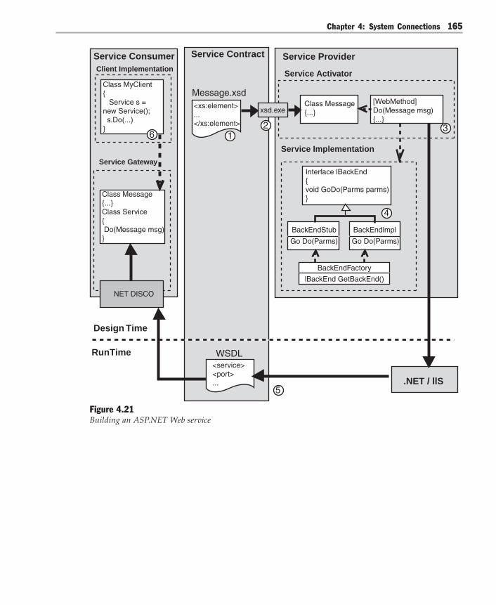
Chapter 4: System Connections 165
<service><port>...
<xs:element>...</xs:element>
1
Service Contract
WSDL
Message.xsd
5
6
Class MyClient{ Service s = new Service(); s.Do(...)}
Class Message{...} Class Service{ Do(Message msg)}
NET DISCO
Service ConsumerClient Implementation
Service Gateway
2
Class Message{...}
[WebMethod]Do(Message msg){...}
Service Provider
Service Activator
Service Implementation
4
3
Interface lBackEnd{void GoDo(Parms parms)}
BackEndStub
Go Do(Parms)
BackEndlmpl
Go Do(Parms)
BackEndFactory
lBackEnd GetBackEnd()
xsd.exe
Design Time
RunTime
.NET / llS
Figure 4.21Building an ASP.NET Web service
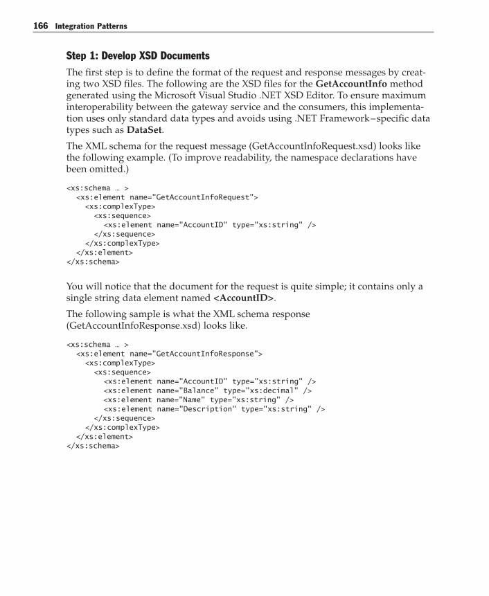
Integration Patterns166
Step 1: Develop XSD DocumentsThe first step is to define the format of the request and response messages by creat-ing two XSD files. The following are the XSD files for the GetAccountInfo methodgenerated using the Microsoft Visual Studio .NET XSD Editor. To ensure maximuminteroperability between the gateway service and the consumers, this implementa-tion uses only standard data types and avoids using .NET Framework – specific datatypes such as DataSet.
The XML schema for the request message (GetAccountInfoRequest.xsd) looks likethe following example. (To improve readability, the namespace declarations havebeen omitted.)
<xs:schema … > <xs:element name="GetAccountInfoRequest"> <xs:complexType> <xs:sequence> <xs:element name="AccountID" type="xs:string" /> </xs:sequence> </xs:complexType> </xs:element></xs:schema>
You will notice that the document for the request is quite simple; it contains only asingle string data element named <AccountID>.
The following sample is what the XML schema response(GetAccountInfoResponse.xsd) looks like.
<xs:schema … > <xs:element name="GetAccountInfoResponse"> <xs:complexType> <xs:sequence> <xs:element name="AccountID" type="xs:string" /> <xs:element name="Balance" type="xs:decimal" /> <xs:element name="Name" type="xs:string" /> <xs:element name="Description" type="xs:string" /> </xs:sequence> </xs:complexType> </xs:element></xs:schema>
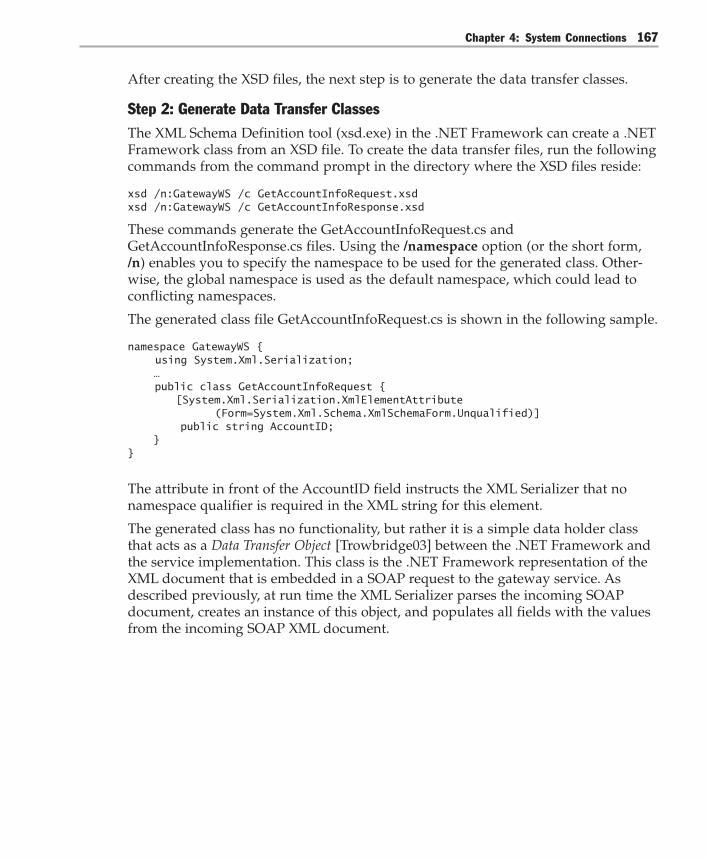
Chapter 4: System Connections 167
After creating the XSD files, the next step is to generate the data transfer classes.
Step 2: Generate Data Transfer ClassesThe XML Schema Definition tool (xsd.exe) in the .NET Framework can create a .NETFramework class from an XSD file. To create the data transfer files, run the followingcommands from the command prompt in the directory where the XSD files reside:
xsd /n:GatewayWS /c GetAccountInfoRequest.xsdxsd /n:GatewayWS /c GetAccountInfoResponse.xsd
These commands generate the GetAccountInfoRequest.cs andGetAccountInfoResponse.cs files. Using the /namespace option (or the short form,/n) enables you to specify the namespace to be used for the generated class. Other-wise, the global namespace is used as the default namespace, which could lead toconflicting namespaces.
The generated class file GetAccountInfoRequest.cs is shown in the following sample.
namespace GatewayWS { using System.Xml.Serialization; … public class GetAccountInfoRequest { [System.Xml.Serialization.XmlElementAttribute (Form=System.Xml.Schema.XmlSchemaForm.Unqualified)] public string AccountID; }}
The attribute in front of the AccountID field instructs the XML Serializer that nonamespace qualifier is required in the XML string for this element.
The generated class has no functionality, but rather it is a simple data holder classthat acts as a Data Transfer Object [Trowbridge03] between the .NET Framework andthe service implementation. This class is the .NET Framework representation of theXML document that is embedded in a SOAP request to the gateway service. Asdescribed previously, at run time the XML Serializer parses the incoming SOAPdocument, creates an instance of this object, and populates all fields with the valuesfrom the incoming SOAP XML document.
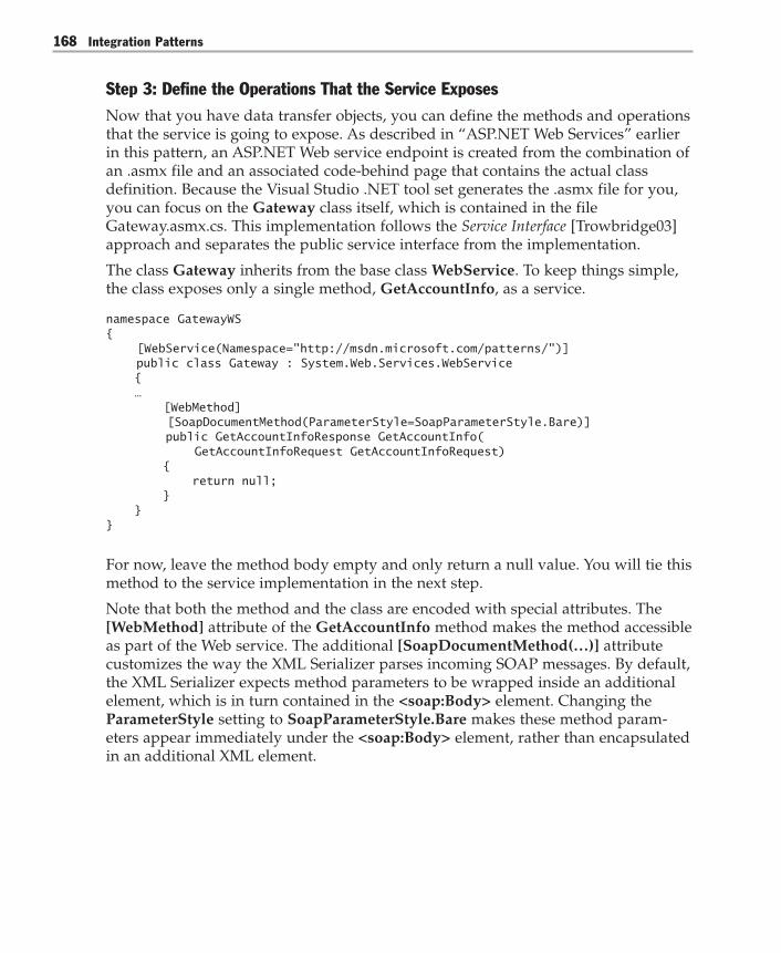
Integration Patterns168
Step 3: Define the Operations That the Service ExposesNow that you have data transfer objects, you can define the methods and operationsthat the service is going to expose. As described in “ASP.NET Web Services” earlierin this pattern, an ASP.NET Web service endpoint is created from the combination ofan .asmx file and an associated code-behind page that contains the actual classdefinition. Because the Visual Studio .NET tool set generates the .asmx file for you,you can focus on the Gateway class itself, which is contained in the fileGateway.asmx.cs. This implementation follows the Service Interface [Trowbridge03]approach and separates the public service interface from the implementation.
The class Gateway inherits from the base class WebService. To keep things simple,the class exposes only a single method, GetAccountInfo, as a service.
namespace GatewayWS{ [WebService(Namespace="http://msdn.microsoft.com/patterns/")] public class Gateway : System.Web.Services.WebService { … [WebMethod] [SoapDocumentMethod(ParameterStyle=SoapParameterStyle.Bare)] public GetAccountInfoResponse GetAccountInfo( GetAccountInfoRequest GetAccountInfoRequest) { return null; } }}
For now, leave the method body empty and only return a null value. You will tie thismethod to the service implementation in the next step.
Note that both the method and the class are encoded with special attributes. The[WebMethod] attribute of the GetAccountInfo method makes the method accessibleas part of the Web service. The additional [SoapDocumentMethod(…)] attributecustomizes the way the XML Serializer parses incoming SOAP messages. By default,the XML Serializer expects method parameters to be wrapped inside an additionalelement, which is in turn contained in the <soap:Body> element. Changing theParameterStyle setting to SoapParameterStyle.Bare makes these method param-eters appear immediately under the <soap:Body> element, rather than encapsulatedin an additional XML element.

Chapter 4: System Connections 169
The following example shows a SOAP message that causes the GetAccountInfomethod of the Gateway.asmx Web service to be invoked.…<soap:Envelope xmlns:xsi="http://www.w3.org/2001/XMLSchema-instance" xmlns:xsd="http://www.w3.org/2001/XMLSchema" xmlns:soap="http://schemas.xmlsoap.org/soap/envelope/"> <soap:Body> <GetAccountInfoRequest xmlns="http://msdn.microsoft.com/patterns"> <AccountID xmlns="">1234567</AccountID> </GetAccountInfoRequest> </soap:Body></soap:Envelope>
The <soap:Body> element contains a <GetAccountInfoRequest> element. Thiselement corresponds to the single parameter that the GetAccountInfo methodreceives.
Without the ParameterStyle setting, the SOAP request for the same method wouldlook like the following sample. Note that an additional GetAccountInfo nodebeneath the <soap:Body> element wraps the method parameters.…<soap:Envelope xmlns:xsi="http://www.w3.org/2001/XMLSchema-instance" xmlns:xsd="http://www.w3.org/2001/XMLSchema" xmlns:soap="http://schemas.xmlsoap.org/soap/envelope/"> <soap:Body> <GetAccountInfo xmlns="http://msdn.microsoft.com/patterns/"> <GetAccountInfoRequest xmlns="http://msdn.microsoft.com/patterns"> <AccountID xmlns="">1234567</AccountID> </GetAccountInfoRequest> </GetAccountInfo> </soap:Body></soap:Envelope>
Because the method receives all the necessary data elements inside a single datatransfer object, the additional wrapping is not required and makes the SOAP mes-sage unnecessarily verbose. Therefore, set the ParameterStyle to Bare.
Step 4: Connect the Service Interface to the Service ImplementationNow that you have built the service interface and have encoded it with the neces-sary Web service attributes, you need to link the still-empty GetAccountInfomethod to the actual service implementation. One option is to insert the code thatimplements the service into the GetAccountInfo method of the Gateway class.However, this approach has a number of drawbacks.

Integration Patterns170
First, the Gateway class inherits from the WebService base class. That means thatthe class cannot be part of a separate inheritance tree that the service implementa-tion may require.
Second, tying together the Web service interface and the implementation makes itharder to test the implementation outside the Web services context.
Third, the functions that the service implementation provides may not exactly matchthe service interface definition. For example, the service implementation may re-quire multiple calls to fine-grained methods, whereas the Web service interfaceshould expose coarse-grained functions. Or, the service implementation may use.NET Framework – specific data types, such as DataSets, that you are seeking toavoid in the public Web service interface. As a result, the service may need to con-tain logic to arbitrate between the public Web service interface and the internalimplementation.
Finally, tying the Web service directly to the implementation means that the Webservice can be functional only when the service implementation is running and isavailable. That may not always be the case if the actual service implementationresides in an existing system. For example, many mainframe systems have offlinetimes when they are not available for online requests. As the Web service is weavedinto a larger solution, these outages could hinder testing. For testing purposes, itwould be very convenient to be able to replace the service implementation with adummy implementation without affecting the service interface.
All these problems can be solved with a combination of well-known design patternsthat is shown in Figure 4.22. The first step is to separate the interface of the servicefunctionality from the implementation — for example, the mainframe access. You cando so by applying the Separated Interface pattern [Fowler03]. The interfaceIGlobalBank is a generic interface that represents the functions provided by themainframe system, but it has no dependency on the server running HIS. The classGlobalHIS implements the methods specified in this interface by connecting to themainframe through HIS.

Chapter 4: System Connections 171
Gateway IGlobalBank
GlobalStub GlobalHIS HIS
GlobalPlugin Factory
<<create>> <<create>>
Figure 4.22Separating the service implementation from the service interface
After you have separated the interface from the implementation, you can create aService Stub [Fowler03]. A service stub is a dummy implementation of an externalservice that reduces external dependencies during testing. The GlobalStub servicestub implements the same IGlobalBank interface but does not actually connect tothe mainframe computer. Instead, it simulates the mainframe functions internally.
Now that you have two implementations, you have to decide which one to use. Youwant to be able to switch between the dummy implementation and the real imple-mentation without having to change any code or having to recompile. Therefore,this example uses a Plugin [Fowler03]. Plugin links classes during configurationrather than compilation. You implement the Plugin inside the GlobalPlugInFactoryclass. The factory class reads the name of the implementing class from a configura-tion file so that you can switch between GlobalStub and GlobalHIS at run time bychanging the application configuration file.

Integration Patterns172
What is left for the Gateway class to do? It has to call the GlobalPlugInFactory classto obtain a reference to an implementation of the IGlobalBank interface. Next, it hasto invoke the appropriate method in the interface. The names and types of theparameters of the service implementation may differ from the XML schemas thatyou created, so the Gateway class may have to perform simple mapping functionsbetween the two data representations.
Even though the implementation of these extra classes is not strictly necessary tocreate a working Web service, these patterns simplify testing tremendously and arewell worth the additional coding effort. It turns out that the implementation of eachclass is actually quite simple. The implementation involves the following steps:1. Create an interface.2. Create service implementations.3. Create the plug-in factory.4. Implement the Web service method.
Let’s walk through these steps one by one.
Step 4.1: Create an Interface
First, create an interface for the service implementation. The following code is fromthe IGlobalBank.cs file. The code references the AccountInfo class. The AccountInfoclass is used by the service implementation. Note that this interface and the datatransfer class have no dependency on a specific serviceimplementation.
public interface IGlobalBank{ // Throws ArgumentException if account does not exist. AccountInfo GetAccountInfo (string AccountID);}
public class AccountInfo{ public string accountID; public string name; public string description; public decimal balance;
public AccountInfo(string accountID, string name, string description, decimal balance) { this.accountID = accountID; this.name = name; this.description = description; this.balance = balance; }}

Chapter 4: System Connections 173
Step 4.2: Create the Service Implementations
Next, create two implementations of the interface as shown. Create one that is asimple stub, and create another one that connects to the mainframe system throughHIS.
The two implementation classes are named GlobalHIS and GlobalStub. GlobalHISconnects to the external system. In the example, the mainframe gateway is theexternal system. The class implements the IGlobalBank interface.
public class GlobalHIS : IGlobalBank{ … public AccountInfo GetAccountInfo(string accountID) { decimal balance = 0.00m; string name = ""; object [] contextArray = null;
TCP_LinkTRM_NET.GlobalBank bank = new TCP_LinkTRM_NET.GlobalBank (); bank.cedrbank (ref name ,ref accountID ,ref balance, ref contextArray); AccountInfo info = new AccountInfo(accountID, "","", balance); return info; }}
The GlobalStub class provides another implementation of the IGlobalBank inter-face but is a simple stub without any dependency on external systems. It uses aninternal accounts collection to simulate account balances. For testing purposes, theclass constructor initializes this collection by using hard-coded values.
public class GlobalStub : IGlobalBank{ static IDictionary accounts = (IDictionary) new Hashtable();
public GlobalStub() { if (accounts.Count == 0) { accounts.Add("123", new AccountInfo("123", "TestAccount", "TestDescription", 777.12m)); } }
public AccountInfo GetAccountInfo(string accountID) { if (!accounts.Contains(accountID)) throw new ArgumentException("Account does not exist"); return (AccountInfo)accounts[accountID]; }}

Integration Patterns174
Step 4.3: Create the Plug-in Factory
Now that you have created two implementations of the IGlobalBank interface, youneed to decide the implementation that you want to use at run time. This is thepurpose of the GlobalBankPlugInFactory class. The class reads the name of theclass to be used from the configuration file and then creates an instance of that class.It returns a reference to the newly created object to the service interface, but thereference is cast to the IGlobalStub interface. This way the service interface is notdependent on the implementation that was chosen.
public class GlobalBankPlugInFactory{ static string globalBankImplName =System.Configuration.ConfigurationSettings.AppSettings["GlobalBankImpl"];
static public GlobalBank.IGlobalBank GetGlobalBankImpl() { Type globalBankImplType = Type.GetType(GetImplementationClassName()); if (globalBankImplType == null) throw new TypeLoadException("Cannot load type " + globalBankImplName); GlobalBank.IGlobalBank bank =(GlobalBank.IGlobalBank)Activator.CreateInstance(globalBankImplType); return bank; }
static public string GetImplementationClassName() { if (globalBankImplName == null) globalBankImplName = "GlobalBank.GlobalStub"; return globalBankImplName; }}
For the Plugin class to be functional, you need to add the following entry to theWeb.config file.
<appSettings> <add key="GlobalBankImpl" value="GlobalBank.GlobalStub"/></appSettings>

Chapter 4: System Connections 175
Step 4.4: Implement the Web Service Method
Now that you have defined the implementation classes, you can finally fill in theimplementation code to the GetAccountInfo method of the Gateway.asmx Webservice as follows.
[WebMethod][SoapDocumentMethod(ParameterStyle=SoapParameterStyle.Bare)]public GetAccountInfoResponse GetAccountInfo( GetAccountInfoRequest GetAccountInfoRequest) { GlobalBank.IGlobalBank bank =GlobalBank.GlobalBankPlugInFactory.GetGlobalBankImpl();
GlobalBank.AccountInfo globalAccountInfo =bank.GetAccountInfo(GetAccountInfoRequest.AccountID);
return BuildAccountInfo(globalAccountInfo); }
private GetAccountInfoResponse BuildAccountInfo(GlobalBank.AccountInfoglobalAccountInfo) { GetAccountInfoResponse response = new GetAccountInfoResponse(); response.AccountID = globalAccountInfo.accountID; response.Balance = globalAccountInfo.balance; response.Name = globalAccountInfo.name; response.Description = globalAccountInfo.description; return response; }
The preparation you have done pays off. The implementation of the Web serviceinterface method now consists of three easy steps:1. Obtain a reference to the IGlobalBank interface.2. Invoke the service implementation by using the reference.3. Construct the correct response format to return to the consumer.
Each step can be implemented in a single line of code. Step 3 is implemented in aBuildAccountInfoResponse private helper method. In this contrived example, itmight appear unnecessary to use separate structures for GetAccountInfoResponseand GlobalBank.AccountInfo because they are essentially identical. However, eachstructure is likely to undergo a different change cycle over time. Including thistranslation step allows the gateway to accommodate changes to either the HISinterface or to the gateway interface without affecting both interfaces.
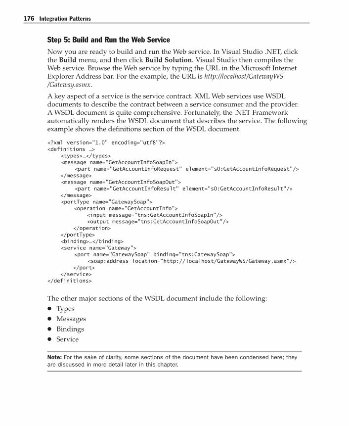
Integration Patterns176
Step 5: Build and Run the Web ServiceNow you are ready to build and run the Web service. In Visual Studio .NET, clickthe Build menu, and then click Build Solution. Visual Studio then compiles theWeb service. Browse the Web service by typing the URL in the Microsoft InternetExplorer Address bar. For the example, the URL is http://localhost/GatewayWS/Gateway.asmx.
A key aspect of a service is the service contract. XML Web services use WSDLdocuments to describe the contract between a service consumer and the provider.A WSDL document is quite comprehensive. Fortunately, the .NET Frameworkautomatically renders the WSDL document that describes the service. The followingexample shows the definitions section of the WSDL document.
<?xml version="1.0" encoding="utf8"?><definitions …> <types>…</types> <message name="GetAccountInfoSoapIn"> <part name="GetAccountInfoRequest" element="s0:GetAccountInfoRequest"/> </message> <message name="GetAccountInfoSoapOut"> <part name="GetAccountInfoResult" element="s0:GetAccountInfoResult"/> </message> <portType name="GatewaySoap"> <operation name="GetAccountInfo"> <input message="tns:GetAccountInfoSoapIn"/> <output message="tns:GetAccountInfoSoapOut"/> </operation> </portType> <binding>…</binding> <service name="Gateway"> <port name="GatewaySoap" binding="tns:GatewaySoap"> <soap:address location="http://localhost/GatewayWS/Gateway.asmx"/> </port> </service></definitions>
The other major sections of the WSDL document include the following:● Types● Messages● Bindings● Service
Note: For the sake of clarity, some sections of the document have been condensed here; theyare discussed in more detail later in this chapter.
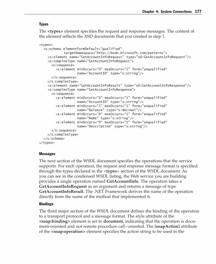
Chapter 4: System Connections 177
Types
The <types> element specifies the request and response messages. The content ofthe element reflects the XSD documents that you created in step 1.
<types> <s:schema elementFormDefault="qualified" targetNamespace="http://msdn.microsoft.com/patterns"> <s:element name="GetAccountInfoRequest" type="s0:GetAccountInfoRequest"/> <s:complexType name="GetAccountInfoRequest"> <s:sequence> <s:element minOccurs="0" maxOccurs="1" form="unqualified" name="AccountID" type="s:string"/> </s:sequence> </s:complexType> <s:element name="GetAccountInfoResult" type="s0:GetAccountInfoResponse"/> <s:complexType name="GetAccountInfoResponse"> <s:sequence> <s:element minOccurs="0" maxOccurs="1" form="unqualified" name="AccountID" type="s:string"/> <s:element minOccurs="1" maxOccurs="1" form="unqualified" name="Balance" type="s:decimal"/> <s:element minOccurs="0" maxOccurs="1" form="unqualified" name="Name" type="s:string"/> <s:element minOccurs="0" maxOccurs="1" form="unqualified" name="Description" type="s:string"/> </s:sequence> </s:complexType> </s:schema></types>
Messages
The next section of the WSDL document specifies the operations that the servicesupports. For each operation, the request and response message format is specifiedthrough the types declared in the <types> section of the WSDL document. Asyou can see in the condensed WSDL listing, the Web service you are buildingprovides a single operation named GetAccountInfo. The operation takes aGetAccountInfoRequest as an argument and returns a message of typeGetAccountInfoResult. The .NET Framework derives the name of the operationdirectly from the name of the method that implemented it.
Bindings
The third major section of the WSDL document defines the binding of the operationto a transport protocol and a message format. The style attribute of the<soap:binding> element is set to document, indicating that the operation is docu-ment-oriented and not remote procedure call – oriented. The [soapAction] attributeof the <soap:operation> element specifies the action string to be used in the

Integration Patterns178
SOAPAction HTTP header. As explained in “ASP.NET Web Services,” the .NETFramework uses this string to determine the method to execute.
The soap:body elements describe that the message format will be literal, meaningthat the body portion of an incoming SOAP request looks exactly as specified in thetypes section of the document without any additional wrapping or encoding. Thespecified style of SOAP message exchange is also referred to as doc/literal.
<binding name="GatewaySoap" type="tns:GatewaySoap"> <soap:binding transport="http://schemas.xmlsoap.org/soap/http" style="document"/> <operation name="GetAccountInfo"> <soap:operation style="document" soapAction="http://msdn.microsoft.com/patterns/GetAccountInfo" /> <input> <soap:body use="literal"/> </input> <output> <soap:body use="literal"/> </output> </operation></binding>
Service
The last part of the WSDL document specifies an address for the service. The servicein the example is available through the URL http://localhost/GatewayWS/Gateway.asmx.
As you can see, you can save a significant amount of work by having the .NETFramework generate the WSDL document for you rather than coding it manually.
Step 6: Create a Test ClientNow that the service is available online and it is properly described by a servicecontract in the form of a WSDL document, you are ready to create a client applica-tion that consumes the service.
To create a test client that accesses the Web service, create a new ASP.NET project.Use the Add Web Reference Wizard in Visual Studio .NET Solution Explorer tocreate a reference to the gateway Web service. You can also use the Web ServicesDescription Language tool (Wsdl.exe). This command-line tool creates proxy classesfrom WSDL. Compiling this proxy class into an application and then calling themethod of this proxy class causes the proxy class to package a SOAP request acrossHTTP and to receive the SOAP-encoded response.
You can use these proxy classes later to generate automated test cases by using testtools such as NUnit (http://www.nunit.org).
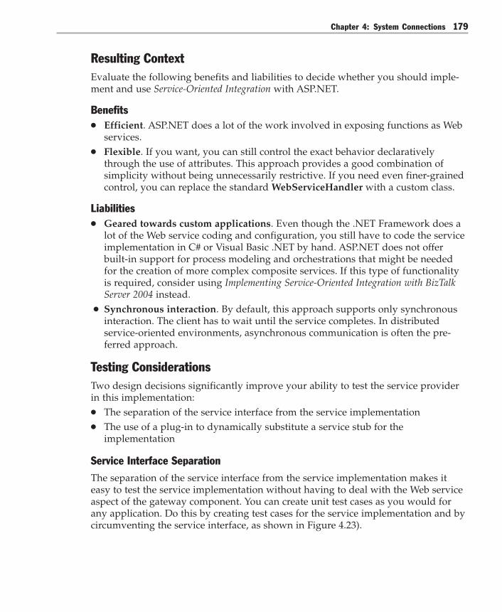
Chapter 4: System Connections 179
Resulting ContextEvaluate the following benefits and liabilities to decide whether you should imple-ment and use Service-Oriented Integration with ASP.NET.
Benefits● Efficient. ASP.NET does a lot of the work involved in exposing functions as Web
services.● Flexible. If you want, you can still control the exact behavior declaratively
through the use of attributes. This approach provides a good combination ofsimplicity without being unnecessarily restrictive. If you need even finer-grainedcontrol, you can replace the standard WebServiceHandler with a custom class.
Liabilities● Geared towards custom applications. Even though the .NET Framework does a
lot of the Web service coding and configuration, you still have to code the serviceimplementation in C# or Visual Basic .NET by hand. ASP.NET does not offerbuilt-in support for process modeling and orchestrations that might be neededfor the creation of more complex composite services. If this type of functionalityis required, consider using Implementing Service-Oriented Integration with BizTalkServer 2004 instead.
● Synchronous interaction. By default, this approach supports only synchronousinteraction. The client has to wait until the service completes. In distributedservice-oriented environments, asynchronous communication is often the pre-ferred approach.
Testing ConsiderationsTwo design decisions significantly improve your ability to test the service providerin this implementation:● The separation of the service interface from the service implementation● The use of a plug-in to dynamically substitute a service stub for the
implementation
Service Interface SeparationThe separation of the service interface from the service implementation makes iteasy to test the service implementation without having to deal with the Web serviceaspect of the gateway component. You can create unit test cases as you would forany application. Do this by creating test cases for the service implementation and bycircumventing the service interface, as shown in Figure 4.23).
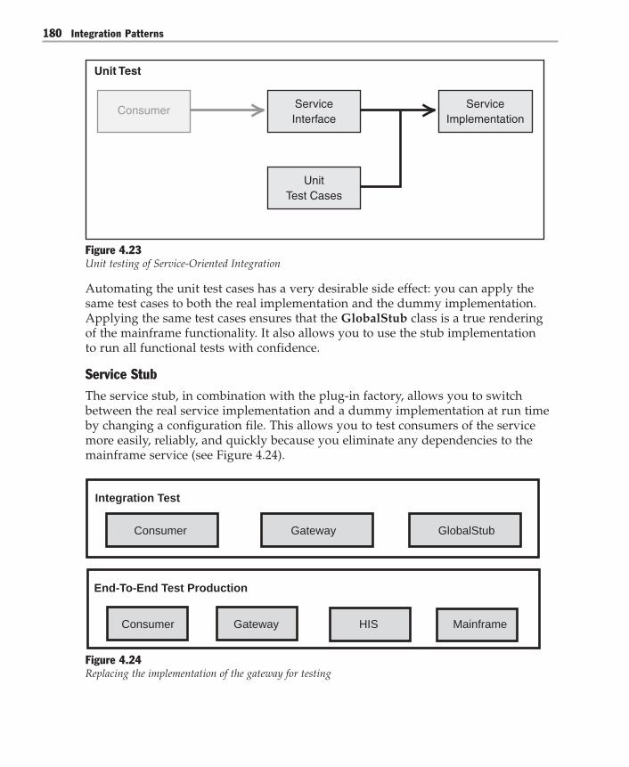
Integration Patterns180
ServiceImplementation
Consumer ServiceInterface
UnitTest Cases
Unit Test
Figure 4.23Unit testing of Service-Oriented Integration
Automating the unit test cases has a very desirable side effect: you can apply thesame test cases to both the real implementation and the dummy implementation.Applying the same test cases ensures that the GlobalStub class is a true renderingof the mainframe functionality. It also allows you to use the stub implementationto run all functional tests with confidence.
Service StubThe service stub, in combination with the plug-in factory, allows you to switchbetween the real service implementation and a dummy implementation at run timeby changing a configuration file. This allows you to test consumers of the servicemore easily, reliably, and quickly because you eliminate any dependencies to themainframe service (see Figure 4.24).
Integration Test
Consumer
Consumer
Gateway
Gateway
GlobalStub
End-To-End Test Production
HIS Mainframe
Figure 4.24Replacing the implementation of the gateway for testing

Chapter 4: System Connections 181
You can be assured that the switch does not affect the behavior of the gatewaybecause both the dummy (stub) implementation and the Host Integration Serverinterface have been unit-tested by using the same suite of unit tests.
Security ConsiderationsThe Web service implementation presented here does not incorporate any securityconsiderations. This may be undesirable because the Web service exposes sensitiveaccount data that resides in the bank’s mainframe computer. Even though the Webservice resides behind the firewall, you would not want anyone with Visual Studio.NET and a little programming skill to create a client to this service to retrievecustomers’ account balances.
Security has been widely recognized as a critical element for the success of Webservices. Microsoft has partnered with IBM and VeriSign to develop the Web Ser-vices Security (WS-Security) specification. This specification describes how SOAPmessages can be augmented with security certificates. The WS-Security specificationis currently implemented by Web Services Enhancements (WSE) for Microsoft .NET.
Acknowledgments[Fowler03] Fowler, Martin. Patterns of Enterprise Application Architecture. Addison-Wesley, 2003.
[Skonnard03] Skonnard, Aaron. “How ASP.NET Web Services Work.” MSDN Library,May 2003. Available at:http://msdn.microsoft.com/library/default.asp?url=/library/en-us/dnwebsrv/html/howwebmeth.asp.
[Trowbridge03] Trowbridge, David; Dave Mancini, Dave Quick, Gregor Hohpe,James Newkirk, and David Lavigne. Enterprise Solution Patterns Using Microsoft.NET. Microsoft Press, 2003. Also available on the MSDN Architecture Center at:http://msdn.microsoft.com/architecture/patterns/default.aspx?pull=/library/en-us/dnpatterns/html/Esp.asp.

Integration Patterns182
Implementing Service-Oriented Integration with BizTalkServer 2004
ContextYou are connecting two or more systems by using Service-Oriented Integration. Theservice implementation requires the orchestration of multiple functions.
BackgroundIn the Global Bank scenario, the customer can view his or her balances for all ac-counts, including loan accounts, on a single page. To provide this function, the Webapplication server interacts with multiple systems to retrieve the required informa-tion. The loan accounts may reside on multiple external loan systems that are oper-ated by subsidiaries that were acquired over time. Figure 4.25 shows how the Webapplication server interacts with the multiple systems to display the account infor-mation in the customer’s Web browser.
BizTalk Server
LoanSystem
LoanSystem
Payment System
WebApplication
Server
CRM Mainframe
Browser
1,000
2,360
230,000
11,543
1,234Credit card
Car
Home
Savings
Checking
Figure 4.25Aggregated account balances from multiple banks

Chapter 4: System Connections 183
To hide the complexity of interacting with external loan systems, you want to designa service that the Web application server can easily access by using a singleGetOtherLoans request.
Implementation StrategyThis pattern implements a Microsoft BizTalk Server 2004 orchestration and exposesit as a Web service. Before discussing detailed steps, it is helpful to review theconcept of Service-Oriented Integration and to review some details about BizTalkServer orchestrations.
Service-Oriented IntegrationService-Oriented Integration connects applications by exchanging documents. In manycases, these documents are represented in XML format. The following code shows adocument passed in a SOAP envelope.)<?xml version="1.0" encoding="utf-8"?><soap:Envelope> <soap:Body> <LoanBalanceRequest> <MasterCustomerID>12345678</MasterCustomerID> <CorrelationID>1100222</CorrelationID> </LoanBalanceRequest> </soap:Body></soap:Envelope>
Service-Oriented Integration hides the complexity of the underlying service very well.For example, the service might execute a complex process internally that has manyparallel threads of activity. However, the complex internal process does not affectthe service interface at all (see Figure 4.26).
ServiceInterface
<CustomerID> 12345678</CustomerID><CorrelationID> 1100222</CorrelationID>
Document Complex Interactions
Figure 4.26Complexity hidden behind a service-oriented interface
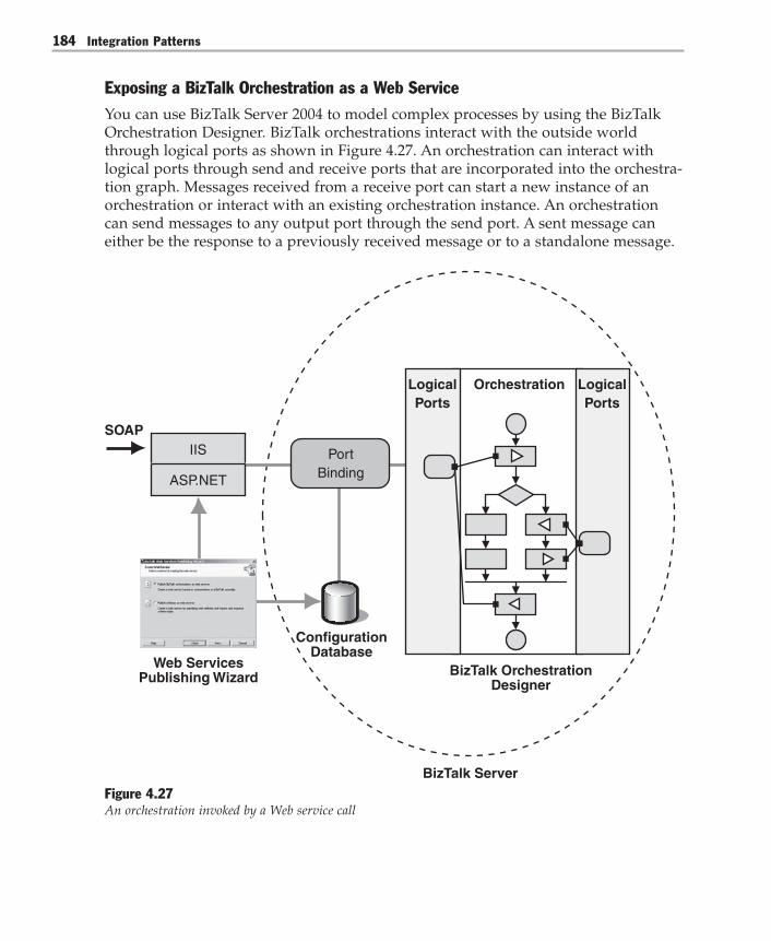
Integration Patterns184
Exposing a BizTalk Orchestration as a Web ServiceYou can use BizTalk Server 2004 to model complex processes by using the BizTalkOrchestration Designer. BizTalk orchestrations interact with the outside worldthrough logical ports as shown in Figure 4.27. An orchestration can interact withlogical ports through send and receive ports that are incorporated into the orchestra-tion graph. Messages received from a receive port can start a new instance of anorchestration or interact with an existing orchestration instance. An orchestrationcan send messages to any output port through the send port. A sent message caneither be the response to a previously received message or to a standalone message.
LogicalPorts
Orchestration LogicalPorts
ConfigurationDatabase
SOAP
BizTalk OrchestrationDesigner
Web ServicesPublishing Wizard
ASP.NET
IIS PortBinding
BizTalk ServerFigure 4.27An orchestration invoked by a Web service call

Chapter 4: System Connections 185
Logical ports can be bound to physical ports at design time or at deployment time.Physical ports specify a transport type, such as File, File Transfer Protocol (FTP),HTTP, or SOAP. Physical ports also specify a physical location, such as a directoryname or a URL. This separation of logical and physical ports allows you to createand reuse orchestrations without being tied to specific directory names or URLs. Youcan specify a physical Web port by selecting the SOAP transport protocol and byspecifying a URL.
After you design an orchestration in BizTalk Server, you can expose it as a Webservice to be invoked from other applications. The BizTalk Web Services PublishingWizard supports this task, generating both a physical port definition and anASP.NET Web service that invokes the orchestration when it receives a SOAP re-quest. For a more detailed description of ASP.NET Web services, see ImplementingService-Oriented Integration with ASP.NET.
The following steps are necessary to create a BizTalk orchestration and to expose itas a Web service to be consumed by other applications. To illustrate this procedure,all steps here are performed manually. However, you can automate some steps byscripting to the BizTalk Windows Management Instrumentation (WMI) interface.
� To expose a BizTalk orchestration as a Web service1. Define the message schemas for inbound and outbound messages. The mes-
sage schemas define the format of the messages that the orchestration receivesand sends. Ultimately, the Web Services Description Language (WSDL) documentgenerated by the ASP.NET Web service uses these message schemas to specify therequired format for inbound and outbound SOAP messages.
2. Define logical request-response ports. A logical port is required so that theorchestration can receive and send messages. A request-response port is a portthat receives a request message and that sends a response within the same inter-action.
3. Define the orchestration and connect it to the logical port. The orchestrationencapsulates the tasks that the service needs to execute internally. Connecting tothe logical port starts a new instance of the orchestration every time a newmessage arrives on the port.
4. Build and deploy the orchestration. An orchestration has to be built and de-ployed to the global assembly cache and to the BizTalk Management databasebefore it can be executed. You use the BizTalk Deployment Wizard to deploy theorchestration.
5. Run the BizTalk Web Services Publishing Wizard. The wizard creates andcompiles a Microsoft Visual Studio project for an ASP.NET Web service. If youselect the Create BizTalk Receive Location option, the wizard also creates aphysical port definition in the BizTalk configuration database.
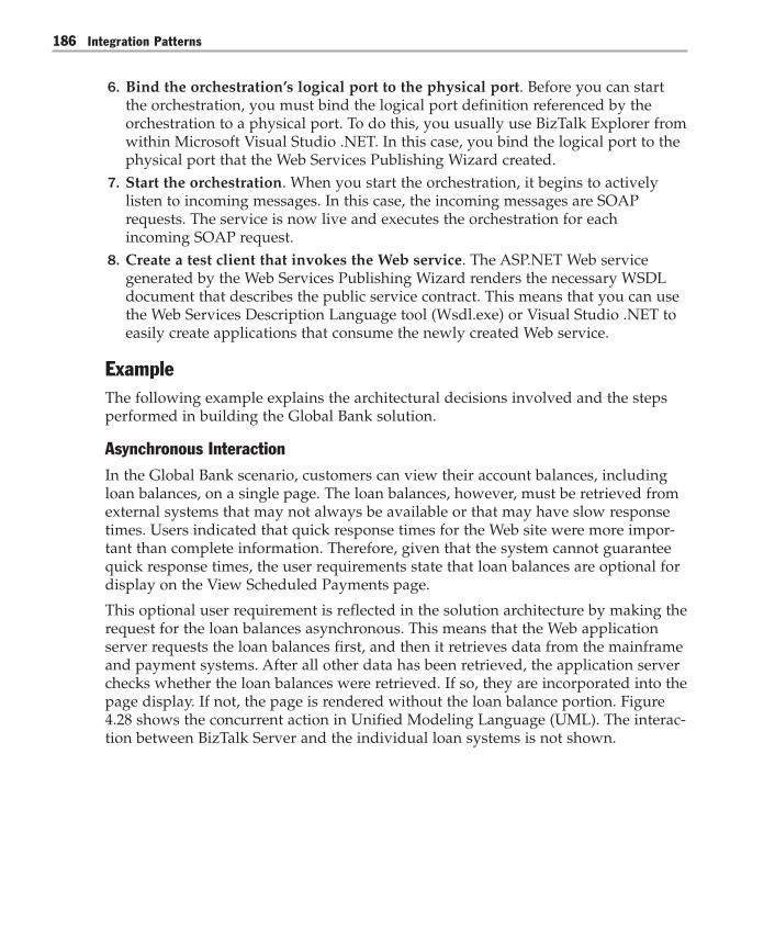
Integration Patterns186
6. Bind the orchestration’s logical port to the physical port. Before you can startthe orchestration, you must bind the logical port definition referenced by theorchestration to a physical port. To do this, you usually use BizTalk Explorer fromwithin Microsoft Visual Studio .NET. In this case, you bind the logical port to thephysical port that the Web Services Publishing Wizard created.
7. Start the orchestration. When you start the orchestration, it begins to activelylisten to incoming messages. In this case, the incoming messages are SOAPrequests. The service is now live and executes the orchestration for eachincoming SOAP request.
8. Create a test client that invokes the Web service. The ASP.NET Web servicegenerated by the Web Services Publishing Wizard renders the necessary WSDLdocument that describes the public service contract. This means that you can usethe Web Services Description Language tool (Wsdl.exe) or Visual Studio .NET toeasily create applications that consume the newly created Web service.
ExampleThe following example explains the architectural decisions involved and the stepsperformed in building the Global Bank solution.
Asynchronous InteractionIn the Global Bank scenario, customers can view their account balances, includingloan balances, on a single page. The loan balances, however, must be retrieved fromexternal systems that may not always be available or that may have slow responsetimes. Users indicated that quick response times for the Web site were more impor-tant than complete information. Therefore, given that the system cannot guaranteequick response times, the user requirements state that loan balances are optional fordisplay on the View Scheduled Payments page.
This optional user requirement is reflected in the solution architecture by making therequest for the loan balances asynchronous. This means that the Web applicationserver requests the loan balances first, and then it retrieves data from the mainframeand payment systems. After all other data has been retrieved, the application serverchecks whether the loan balances were retrieved. If so, they are incorporated into thepage display. If not, the page is rendered without the loan balance portion. Figure4.28 shows the concurrent action in Unified Modeling Language (UML). The interac-tion between BizTalk Server and the individual loan systems is not shown.
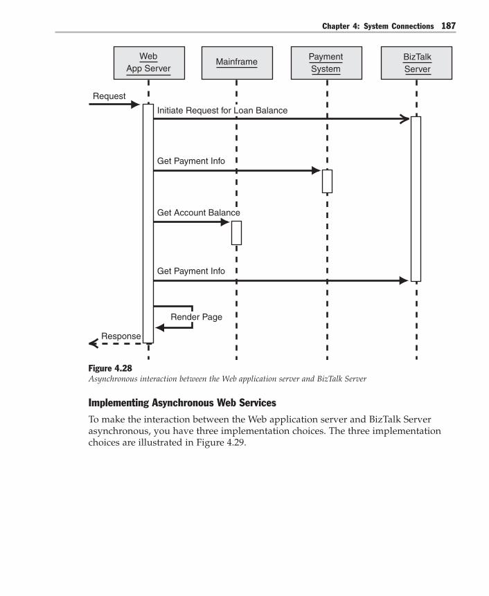
Chapter 4: System Connections 187
Get Payment Info
Get Payment Info
Render Page
Request
Response
WebApp Server
BizTalkServer
Mainframe PaymentSystem
Initiate Request for Loan Balance
Get Account Balance
Figure 4.28Asynchronous interaction between the Web application server and BizTalk Server
Implementing Asynchronous Web ServicesTo make the interaction between the Web application server and BizTalk Serverasynchronous, you have three implementation choices. The three implementationchoices are illustrated in Figure 4.29.

Integration Patterns188
BizTalk ServerWeb Application ServerSOAP Request
SOAP Response
BeginRequest()…DoOtherStuff()…loans = EndRequest()
SOAP Request
SOAP Response
SOAP Request
SOAP Response
SOAP Request
SOAP Response
SOAP Request
SOAP Response
InitiateRequest()…DoOtherStuff()…loans=PollResults()
InitiateRequest()…DoOtherStuff()...loans=getFromCache()
OnSoapMessage(loan){ cache += loan }
A
B
C
Figure 4.29Implementation choices for asynchrony between the Web application server and BizTalk Server
The three implementation choices from Figure 4.29 can be summarized as follows:A. Client-side asynchrony. The Web server issues a single SOAP request by using
the asynchronous Web service API. This API permits the client (in this case, theclient is the Web application server) to continue with other processing and to readthe results of the request at a later time. This approach permits the client tooperate asynchronously while the interaction with BizTalk Server issynchronous.

Chapter 4: System Connections 189
B. Asynchronous interaction with polling. The Web server makes two SOAPrequests to BizTalk Server. One of the SOAP requests initiates the request for loaninformation. This first request only initiates processing on the BizTalk Server sideand returns immediately. Subsequently, the Web server issues a second SOAPrequest to poll for the results. BizTalk Server returns the results if they are avail-able or returns a blank message if they are not yet available. BizTalk Serverdiscards the loan balance results if they become available after the Web serverpolled for them.
C. Asynchronous interaction with callback. The Web server issues a single SOAPrequest to initiate the retrieval of loan information. As with option B, control isreturned immediately to the Web server. The Web server then goes on to otherwork. After BizTalk Server has retrieved the loan information, it sends a SOAPrequest back to the Web server to pass the loan information. It is important tonote that for this part of the interaction, the Web server has to be able to serviceincoming SOAP messages. Therefore, the Web server has to act as the server. TheWeb server stores the loan information in a global cache that is accessible to thethreads that generated the requests. Before the Web server renders the HTMLpage, it checks the global cache to see whether any loan information has arrivedwhile it was interacting with the mainframe and the Customer RelationshipManagement (CRM) systems.
To choose the best option, you need to evaluate the advantages and disadvantages ofeach option. Table 4.4 compares the different options.
Table 4.4: Comparison of the Implementation Choices for Asynchronous Interaction
Option A: Option B: Option C:client-side asynchronous asynchronousasynchrony interaction with interaction with
polling callback
Client-side implementation Low Medium Higheffort
Server-side implementation Low Medium Medium/loweffort
Network traffic Low Higher Higher
Efficient use of resources Poor (for long-runninginteractions) Good Good
Where state is kept Connection Server Client
As you can see, each option has its advantages and disadvantages. Therefore, youmust make your decision based on the priorities that you assign to the individualcriteria.

Integration Patterns190
Although option A may be the easiest to construct, it is essentially a synchronousSOAP interaction that just appears to be asynchronous to the client code because theconnection between the client and the service remains active throughout the wholeinteraction. The use of long-standing connections can quickly deplete system re-sources and can be one of the biggest impediments to a solution’s scalability. Be-cause the loan balance service has to access external loan systems over slow andunreliable connections, the interaction can definitely be long running. Therefore, youshould eliminate option A.
The choice between option B and C is more difficult and depends on whether youwant to maintain the state on the client (the Web application server) or on the serverrunning BizTalk Server. Both servers are multithreaded and quite efficient at keepingstate for many concurrent requests. The choice also depends on where you want toallocate the additional development effort. Do you prefer to put additional effortinto the ASP.NET code on the Web server or into the orchestration design on theserver running BizTalk Server? Option B requires a little extra work on the BizTalkServer to ensure proper correlation and to allow the concurrent servicing of multiplerequests. Option C requires additional coding effort in the Web server to maintainand to clear the global cache. Overall, option B offers the best results for the smallestamount of development effort and is the first choice. However, this discussionhighlights that architectural decisions are not only based on technical considerationsalone but also on development resource constraints and skills preferences.
Building the SolutionBased on the tradeoffs discussed in the previous section, Global Bank decided to useoption B, asynchronous interaction with polling. The next step was to start buildingthe solution. The rest of this example shows you the steps required to build theGlobal Bank solution. Due to the large number of steps involved in creating thesolution, some steps are not covered in full detail.
Step 1: Define the Message Schemas for Inbound and Outbound Messages
To define the format of the request and response messages, create two XML Schema(XSD) files in the Visual Studio .NET XSD Editor. The XSD schema for theLoanBalanceRequest.xsd request message looks like the following schema. Toimprove readability, the namespace declarations are omitted.

Chapter 4: System Connections 191
<xs:schema…> <xs:element name="LoanBalanceRequest"> <xs:complexType> <xs:sequence> <xs:element minOccurs="1" maxOccurs="1" name="MasterCustomerID" type="xs:string" /> </xs:sequence> </xs:complexType> </xs:element></xs:schema>
The document specifies a single MasterCustomerID data field for the request mes-sage. The MasterCustomerID field is common across all systems and can be used tolocate all the customer’s accounts.
In response to the request, the application returns the following acknowledgement(Ack.xsd).
<xs:schema…> <xs:element name="Ack"> <xs:complexType> <xs:sequence> <xs:element name="CorrelationID" type="xs:string" /> </xs:sequence> </xs:complexType> </xs:element></xs:schema>
The only field in this schema is a unique correlation identifier. The orchestrationassigns an ID to this field and uses it later to match (or correlate) the request andresponse messages across the asynchronous communication. For more information,see the Correlation Identifier pattern in Enterprise Integration Patterns [Hohpe04].
After receiving the acknowledgment response from the orchestration, the client pollsthe orchestration for the result.
The client application copies the correlation identifier returned in the acknowledg-ment message (Ack.xsd) into PollReq.xsd. PollReq.xsd has only one field(CorrelationID), as shown in the following schema.
<xs:schema…> <xs:element name="PollReq"> <xs:complexType> <xs:sequence> <xs:element name="CorrelationID" type="xs:string" /> </xs:sequence> </xs:complexType> </xs:element></xs:schema>

Integration Patterns192
The XSD code for the LoanBalanceResponse.xsd response message looks like thefollowing.
<xs:schema …> <xs:element name="LoanBalanceResponse"> <xs:complexType> <xs:sequence> <xs:element name="Loan"> <xs:complexType> <xs:sequence> <xs:element name="Name" type="xs:string" /> <xs:element name="AccountID" type="xs:string" /> <xs:element name="Amount" type="xs:decimal" /> </xs:sequence> </xs:complexType> </xs:element> </xs:sequence> </xs:complexType> </xs:element></xs:schema>
The response message schema defines a list of account names and balances. This listis filled in by the Web service (through the orchestration). The completed message isthen sent back to the client.
Step 2: Define Logical Request-Response Ports
In BizTalk Orchestration Designer, add a port to the orchestration, and then use thePort Configuration Wizard to configure a public request-response port. Figure 4.30indicates the Request-Response option.
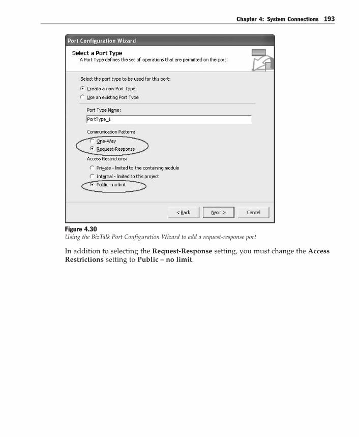
Chapter 4: System Connections 193
Figure 4.30Using the BizTalk Port Configuration Wizard to add a request-response port
In addition to selecting the Request-Response setting, you must change the AccessRestrictions setting to Public – no limit.

Integration Patterns194
Step 3: Define the Orchestration and Connect It to the Logical Port
As described in “Implementing Asynchronous Web Services,” the interaction be-tween the Web server and the BizTalk Server orchestration consists of two parts:● The Web server requests loan information from BizTalk Server.● The Web server polls for results. The BizTalk Server orchestration returns a
response immediately with the results it retrieved up to that point.
Based on Global Bank requirements, the orchestration must:a. Receive the initial request from the Web server. The orchestration creates a new
instance of the orchestration for each request.b. Generate a unique correlation identifier to pass back to the client. The orches-
tration returns the correlation identifier back to the Web server so that it can usethis identifier to poll later for the results.
c. Request the loan balance from multiple backend loan systems. These requestscan be made concurrently. The results from each loan system have to be com-bined into a single message. In this example, both loan systems are accessiblethrough prebuilt Web services.
d. Service the polling request. The orchestration has to be able to receive a pollingrequest from the Web server at any time. When it receives a polling request, theorchestration returns the loan balances if they have been obtained already. Other-wise, the orchestration returns a blank result. The polling request can arrive atany time after the initial request.
e. Time out. If the orchestration does not receive a polling request after an extendedperiod of time (for example, 60 seconds), the orchestration is terminated. Thisfunction keeps orchestration instances from staying active indefinitely while theyare waiting for a polling request.
Figure 4.31 shows these tasks modeled inside a BizTalk Server orchestration.

Chapter 4: System Connections 195
Figure 4.31The BizTalk Server orchestration for loan balances
Now, let’s examine the orchestration tasks in more detail. The letters in the followinglist correlate to the letters in Figure 4.31.
A: Receive the Initial Request from the Web Server
In the Global Bank scenario, the ASP.NET client sends a request for a customer’sloan balances (GetOtherLoans) to BizTalk Server. LoanBalanceRequest.xsd definesthe format of the request. The request contains only the MasterCustomerID field (see“Step 1: Define the Message Schemas for Inbound and Outbound Messages”).
The request is received through the ReceiveReq port in the orchestration (see Figure4.31). After the message is received, the port forwards it to the ReceiveReq Receiveshape. The Activate property of the ReceiveReq Receive shape is set to True, whichactivates the orchestration.

Integration Patterns196
B: Generate a Correlation Identifier and Send Acknowledgment
After the ASP.NET client sends the initial request to BizTalk Server, it receives anacknowledgment message (Ack.xsd). This message contains the CorrelationID field.The CorrelationID field identifies the orchestration instance associated with theinitial request. This field guarantees that incoming messages are associated with thecorrect instance of the orchestration.
To create the correlation ID, you can use a custom C# class that usesSystem.Random to generate and return an ID. That ID is assigned to theCorrelationID field of the Ack.xsd message, and it is returned to the client. Alterna-tively, you can assign one of the BizTalk Server message context properties(BTS.MessageID) as a unique ID to the CorrelationID field of the Ack.xsd message.This is accessible within an Expression shape in the orchestration.
For the CorrelationID field to be accessible to the code in the Expression Editorwindow, you must use the BizTalk Schema Editor to promote it, as shown inFigure 4.32.
Figure 4.32Promoting a schema field
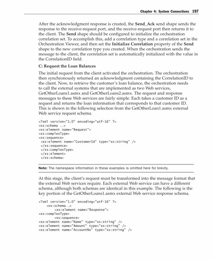
Chapter 4: System Connections 197
After the acknowledgment response is created, the Send_Ack send shape sends theresponse to the receive-request port, and the receive-request port then returns it tothe client. The Send shape should be configured to initialize the orchestrationcorrelation set. To accomplish this, add a correlation type and a correlation set in theOrchestration Viewer, and then set the Initialize Correlation property of the Sendshape to the new correlation type you created. When the orchestration sends themessage to the client, the correlation set is automatically initialized with the value inthe CorrelationID field.
C: Request the Loan Balances
The initial request from the client activated the orchestration. The orchestrationthen synchronously returned an acknowledgment containing the CorrelationID tothe client. Now, to retrieve the customer’s loan balance, the orchestration needsto call the external systems that are implemented as two Web services,GetOtherLoans1.asmx and GetOtherLoans2.asmx. The request and responsemessages to these Web services are fairly simple. Each takes a customer ID as arequest and returns the loan information that corresponds to that customer ID.This is shown in the following selection from the GetOtherLoan1.asmx externalWeb service request schema.
<?xml version="1.0" encoding="utf-16" ?><xs:schema ..><xs:element name="Request"><xs:complexType><xs:sequence> <xs:element name="CustomerId" type="xs:string" /> </xs:sequence> </xs:complexType> </xs:element> </xs:schema>
Note: The namespace information in these examples is omitted here for brevity.
At this stage, the client’s request must be transformed into the message format thatthe external Web services require. Each external Web service can have a differentschema, although both schemas are identical in this example. The following is thekey portion of the GetOtherLoans1.asmx external Web service response schema.
<?xml version="1.0" encoding="utf-16" ?> <xs:schema …> <xs:element name="Response"><xs:complexType> <xs:sequence><xs:element name="Name" type="xs:string" /><xs:element name="Amount" type="xs:string" /><xs:element name="AccountNo" type="xs:string" />

Integration Patterns198
</xs:sequence> </xs:complexType> </xs:element> </xs:schema>
To transform one schema into another, Transform shapes in ConstructWS_Req1 andConstructWS_Req2 map the CustomerId fields of the two schemas. You use theBizTalk Mapper to map the MasterCustomerID field of LoanBalanceRequst.xsd tothe CustomerId field of the Web service’s request schema (see Figure 4.33).
Figure 4.33Using BizTalk Mapper to map request fields
Now that the Web services’ request messages have been constructed, the responsemessages have to be parsed and consumed. In BizTalk Solution Explorer, open theWeb service’s Reference.xsd file. Using the Promote option, distinguish the Name,AccountNo, and Amount elements of the Web service response schema (see Figure4.32). Distinguishing these fields allows the code in the AddLoan1 and AddLoan2Expression shapes to reference their values and use them to construct the responsedocument.

Chapter 4: System Connections 199
Next, you use the response from each Web service to construct aLoanBalanceResponse.xsd response that is returned to the client. To accomplish this,AddLoan1 and AddLoan2 Expression shapes use a custom C# class(LoanInfoCollection) to collect the results returned by each Web service. Each Webservice returns the Name, AccountNo, and Amount for the customer’s loan. Thecustom class aggregates the responses into an XML document which is returned tothe polling client as the LoanBalanceResponse.xsd response. The following is thecode from the Expression property of AddLoan1.
LoanInfoCollection.AddLoan(msgWebServ1_Resp.GetLoanInfoResult.Name,msgWebServ1_Resp.GetLoanInfoResult.Amount,msgWebServ1_Resp.GetLoanInfoResult.AccountNo);
Because all three branches of the parallel action use the LoanInfoCollection class,the AddLoan1 and AddLoan2 Expression shapes are inside synchronized blocks(Scope_LoanInfo1 and Scope_LoanInfo2 respectively). The Transaction Typeproperty of the synchronized blocks is set to Atomic to protect the class from con-current access. For more information about transactions in BizTalk Server, seeImplementing Process Integration with BizTalk Server 2004.
D: Service Polling Request
At this point, the response message has been constructed and is ready to be deliv-ered to the client. The client polls the orchestration by sending a SOAP message toBizTalk Server. The message contains the correlation ID that identifies the instance ofthe orchestration that is associated with this request.
The PollReqResp port is linked to the ReceivePollReq receive shape. TheReceivePollReq receive shape has an important property, Following CorrelationSets. This property is set to the correlation type created earlier in step B, and itallows BizTalk Server to associate the polling request to the correct instance of thisorchestration.
The request message is then assigned the loan information gathered from Webservices by the LoanInfoCollection class within the Construct Response shape ofScope_CreateResponse.
As the final step, the SendPollResp Send shape sends the constructed responsemessage that is mentioned earlier to the PollReqResp port. The PollReqResp portthen sends the constructed response message to the polling client.
E: Time Out
With respect to the polling request, there are two potential scenarios that you haveto design the orchestration to handle properly. In the first scenario, the client maypoll too early, before the orchestration has received a response from external Webservices and constructed the response message. In the second scenario, the client

Integration Patterns200
may not poll at all. If the client does not poll at all, the orchestration instance is leftin an active state forever.
To handle early polling, you must allow the client to poll again if no results arereturned. To accomplish this, you add a loop and set it to run indefinitely. In thiscase, add a Poll_Loop. Note, however, that the loop is limited by the Timeoutproperty value of the orchestration.
To set the Timeout value for the orchestration, set the Transaction Type property toLong Running, and set the Timeout property value to 60 seconds or another appro-priate value. This allows the client enough time to poll for the result and eliminatesthe possibility that an orchestration could run indefinitely.
Step 4: Build and Deploy the Orchestration
Before you build the orchestration, create an assembly key file by typing sn –kSOIwithBizTalk.snk at the command prompt. Copy the file to the project folder,and then enter the file name in the Assembly Key File name property of the projectproperties.
Note: You need to build the LoanInfoCollection assembly that is referenced by the project byusing a strong name assembly key file. You then must deploy it to the global assembly cache.
From the Visual Studio .NET menu, build the solution. This creates a .NET Frame-work assembly called SOIwithBizTalk. You then deploy the SOIwithBizTalkassembly by using the BizTalk Server Deployment Wizard or by using the scriptsthat are included with the BizTalk 2004 SDK.
Step 5: Run the BizTalk Web Services Publishing Wizard
To expose the SOIwithBizTalk assembly that you deployed in step 5 as a Webservice, run the BizTalk Web Services Publishing Wizard. The wizard creates theSOIwithBiztalk_Proxy Web service. The SOIwithBiztalk_Proxy Web service exposesWeb services corresponding to the ReceiveReq and PollReqResp ports.
Step 6: Bind the Orchestration’s Logical Port to the Physical Port
The Web Services Publishing Wizard that you ran in step 4 also created two receiveports for the ReceiveReq and PollReqResp ports, which you can access throughBizTalk Explorer.
Note: The Receive Pipeline property of these ports should be set to XmlReceive. To set thisproperty in BizTalk Explorer, select the port, right-click the port name, and then click Edit on thecontext menu.

Chapter 4: System Connections 201
Next, you need to add two send ports for the GetOtherLoan1 and GetOtherLoan2Web ports. The Receive Pipeline properties of these ports also should be set toXmlReceive instead of the default PassThrough setting.
After you set up the physical ports, bind the orchestration to these ports in BizTalkExplorer. Note that there are two inbound ports and two outbound ports in the PortBinding Properties window of the orchestration. You can also use the BTSDeploycommand line utility and a binding file to bind ports. Use the Export BizTalkassembly binding to file option in BizTalk Deployment Wizard to create the bind-ing file.
Step 7: Start the Orchestration
After binding the logical ports to physical ports, start the orchestration in BizTalkExplorer.
Step 8: Create a Test Client That Invokes the Web Service
To test the orchestration, you need to create a client that consumes the Web servicecreated from the orchestration in step 4. As you saw in step 4, the wizard createdtwo Web services that correspond to the two request-response ports of the orchestra-tion. The following code shows part of the WSDL file for PollReqResp.asmx. For thesake of clarity, some parts of the file are not shown here.
<types> + <s:schema elementFormDefault="qualified" targetNamespace="http://msdn.microsoft.com/soi"> - <s:schema elementFormDefault="qualified" targetNamespace="http://SOIwithBiztalk.PollReq"> <s:element name="PollReq" type="s1:PollReq" /> - <s:complexType name="PollReq"> <s:sequence> <s:element minOccurs="0" maxOccurs="1" form="unqualified"name="CorrelationId" type="s:string" /> </s:sequence> </s:complexType> </s:schema> - <s:schema elementFormDefault="qualified" targetNamespace="http://SOIwithBiztalk.PollResp"> <s:element name="PollResp" type="s2:PollResp" /> - <s:complexType name="PollResp"> - <s:sequence> <s:element minOccurs="0" maxOccurs="1" form="unqualified"name="Loans" type="s2:ArrayOfPollRespLoan" /> </s:sequence> </s:complexType> - <s:complexType name="ArrayOfPollRespLoan"> - <s:sequence> <s:element minOccurs="0" maxOccurs="unbounded" form="unqualified"

Integration Patterns202
name="Loan" type="s2:PollRespLoan" /> </s:sequence> </s:complexType> - <s:complexType name="PollRespLoan"> - <s:sequence> <s:element minOccurs="0" maxOccurs="1" form="unqualified"name="Amount" type="s:string" /> <s:element minOccurs="0" maxOccurs="1" form="unqualified"name="Name" type="s:string" /> <s:element minOccurs="0" maxOccurs="1" form="unqualified"name="AccountNo" type="s:string" /> </s:sequence> </s:complexType> </s:schema> </types>+ <message name="PollReqRespSoapIn">+ <message name="PollReqRespSoapOut">+ <portType name="SOIwithBiztalk_SOIwithBiztalk_Orchestration_PollReqRespSoap">+ <binding name="SOIwithBiztalk_SOIwithBiztalk_Orchestration_PollReqRespSoap"type="s0:SOIwithBiztalk_SOIwithBiztalk_Orchestration_PollReqRespSoap">- <service name="SOIwithBiztalk_SOIwithBiztalk_Orchestration_PollReqResp"> <documentation>BizTalk assembly "SOIwithBiztalk, Version=1.0.0.0,Culture=neutral, PublicKeyToken=c6495a1a84cf8ad3" published web service.</documentation> - <port name="SOIwithBiztalk_SOIwithBiztalk_Orchestration_PollReqRespSoap"binding="s0:SOIwithBiztalk_SOIwithBiztalk_Orchestration_PollReqRespSoap"> <soap:address location="http://localhost/SOIwithBiztalk_Proxy/SOIwithBiztalk_SOIwithBiztalk_Orchestration_PollReqResp.asmx" /> </port> </service></definitions>
The test client is a Windows Form application that uses the NUnit test tool. For moreinformation about this tool, see www.nunit.org. The following test case sends arequest to BizTalk Server, waits, and then polls for the result.
[Test] public void TestRequestAndPollLater() { RequestWS.SOIwithBiztalk_SOIwithBiztalk_Orchestration_ReceiveReqws = newTestSOIwithBiztalk.RequestWS.SOIwithBiztalk_SOIwithBiztalk_Orchestration_ReceiveReq(); RequestWS.Request req = new RequestWS.Request(); req.MasterCustomerID = "1234"; RequestWS.Ack resp = ws.InitialRequest(req);
string corId = resp.CorrelationId; //wait for external services to return response System.Threading.Thread.Sleep(6000); //poll for resultPollWS.SOIwithBiztalk_SOIwithBiztalk_Orchestration_PollReqResp pollws = new

Chapter 4: System Connections 203
TestSOIwithBiztalk.PollWS.SOIwithBiztalk_SOIwithBiztalk_Orchestration_PollReqResp(); PollWS.PollReq pollreq = new TestSOIwithBiztalk.PollWS.PollReq(); pollreq.CorrelationId = corId;
PollWS.PollResp pollresp = pollws.PollReqResp(pollreq);
Assertion.AssertEquals(2, pollresp.Loans.Length); //test results ValidateLoanEntry(pollresp.Loans[0]); ValidateLoanEntry(pollresp.Loans[1]);}
private void ValidateLoanEntry(PollWS.PollRespLoan entry) { // note: the responses do not have to be in order if (entry.AccountNo.Equals("1234")) { Assertion.AssertEquals("1000", entry.Amount); } else if (entry.AccountNo.Equals("5678")) { Assertion.AssertEquals("2000", entry.Amount); } else { Assertion.Fail("Wrong account number"); } }
Resulting ContextThis implementation of Service-Oriented Integration results in the following benefitsand liabilities:
Benefits● Powerful. You can use BizTalk Server 2004 to model complex processes compris-
ing multiple parallel interactions. You can even build a hierarchy of orchestra-tions where one orchestration invokes other orchestrations. BizTalk Server alsoimports important concepts that are critical when developing asynchronous,event-driven solutions. These solutions include correlation, synchronization,timeouts, long-running transactions, and compensating actions.
● Integrated development tools. The BizTalk Server 2004 visual modeling tools areintegrated into Visual Studio .NET. This greatly enhances the developmentexperience for mixed development consisting of actual C# or Visual Basic .NETcode and visual models from maps and orchestrations.
● Operational support. Monitoring and operating Web services solutions can bedifficult. BizTalk Server 2004 includes sophisticated tools to monitor the flow ofmessages and the execution of orchestrations through the Health andActivity Tracker (HAT) tool.

Integration Patterns204
Liabilities● Complexity. Although BizTalk Server 2004 provides many useful features, it also
introduces a series of new concepts, a large number of moving parts, and adifferent development environment than what developers are used to. This canincrease the learning curve for application developers.
Testing ConsiderationsThere are several possible options available when testing this implementation. First,the Web service as a whole can be tested by writing a test client in the .NET Frame-work. To create the test client, create a new C# console application, and use the AddWeb Reference command in Visual Studio Solution Explorer to create a reference tothe orchestration Web service. You can then write test code that invokes the Webservice. Subsequently, you can add automated test cases to this test client by usingtest tools such as NUnit.
After running the test client, you can use the Orchestration Debugger to examinetraces of the orchestration execution. You can access the Orchestration Debuggerfrom the HAT tool and use the Orchestration Debugger in two modes: reportingmode and interactive mode. Reporting mode tracks the execution of each shape inthe orchestration as it occurs. In reporting mode, you can replay the steps or setbreakpoints on the class of orchestration so that you can then debug new instancesin interactive mode. Interactive mode enables you to debug a currently runninginstance. To debug a process interactively, set a breakpoint within an orchestrationwhile in reporting mode, and then submit a new message (create a new instance ofan orchestration). The orchestration will stop at the breakpoint, and you can thenattach the orchestration debugger to that instance.
Security ConsiderationsThe Web service implementation presented here does not address security consider-ations. Appropriate security measures are essential in this scenario because the Webservice exposes sensitive account data that resides in the bank’s mainframe com-puter. Even though the Web service resides behind the firewall, you would not wantunauthorized users to create a client to this service to retrieve customers’ accountbalances.
Security is implemented at multiple levels when exposing an orchestration as a WebService:● Transport security. The BizTalk Web Services Publishing Wizard creates an
ASP.NET virtual directory like any other ASP.NET Web service. SOAP messagessent to this virtual directory can be sent by using HTTPS (encrypted). Addition-ally, the virtual directory can be configured to require basic authentication,NTLM authentication, or even client certificates.

Chapter 4: System Connections 205
● SOAP security. Microsoft has partnered with IBM and VeriSign to develop theWeb Services Security (WS-Security) specification. The WS-Security specificationdescribes how SOAP messages can be augmented with security certificates. TheWS-Security specification is currently implemented by Web Services Enhance-ments (WSE) for Microsoft .NET. The current version of the SOAP adapter doesnot support WS-Security, but this functionality can be supported by using custompipeline components in the BizTalk receive and send pipelines.
● Receive adapter security. The SOAP adapter is run by a BizTalk Server IsolatedHost instance within a specific Microsoft Windows security context. If the BizTalkIsolated Host was installed as trusted, then the user that acquires authenticationwhen running the Web service must be a member of the BizTalk Isolated HostUsers group (this is often the IUSR_computer name account). If the BizTalk Iso-lated Host was not installed as trusted, the ASP.NET account must be a memberof the BizTalk Isolated Host Users group.
● Receive port security. You can configure the receive port to require messages tobe authenticated before they are processed. Messages are authenticated in theResolveParty stage of the receive pipeline by using a client certificate or by usinga Security Identifier (SID). Messages that are not authenticated can either bedropped or saved, but they are not processed.
Operational ConsiderationsMany of the BizTalk receive adapters, including the HTTP and the SOAP adapters,perform batching to optimize throughput and server resource utilization by mini-mizing polling. The default batch size is 10, and there is a delay between polls of onesecond. This means that a single synchronous HTTP post or SOAP call is processed,but because it is not a complete batch, the adapter waits for one second beforepolling again. Therefore, successive calls may be delayed. This is appropriate behav-ior in high-transaction situations, but it is not appropriate behavior for a highlyresponsive system.
To make the HTTP and SOAP adapters more responsive, you can set the registryHttpBatchSize subkey DWORD value in the HKLM\CurrentControlSet\BtsSvc3.0\HttpReceive registry key to 1. Setting this value to 1 affects the maximumthroughput that the adapter is capable of handling.
Acknowledgments[Hohpe04] Hohpe, Gregor, and Bobby Woolf, Enterprise Integration Patterns:Designing, Building, and Deploying Messaging Solutions. Addison-Wesley, 2004.

Integration Patterns206
Presentation Integration
AliasesScreen scraping
ContextYou have multiple independent applications that are organized as functional silos.Each application has a user interface.
ProblemHow do you integrate information systems that were not designed to worktogether?
ForcesTo correctly solve this problem, you need to consider the following forces:● When integrating multiple applications, you should minimize changes to existing
systems because any change to an existing production system represents a riskand might require extensive regression testing.
● Because many computer systems are designed according to the Layered Applica-tion pattern, some of the layers are typically deployed in physical tiers that arenot externally accessible. For example, security policy may require the databasetier of an application to reside on a separate physical server that is not directlyaccessible to other applications. Most Web applications allow external access onlyto the user interface and protect the application and database tiers behindfirewalls.
● Many applications feature little or no separation between business and presenta-tion logic. The only remote components of these applications are simple displayand input devices. These display terminals access the central mainframe com-puter, and the central mainframe computer hosts all business logic and datastorage.
● The business logic layer of many applications is programming-language specificand is not available remotely, unless it was developed on top of a specificremoting technology such as DCOM or Common Object Request Broker Architec-ture (CORBA).

Chapter 4: System Connections 207
● Directly accessing an application’s database layers can cause corruption ofapplication data or functionality. In most applications, important business rulesand validations reside in the business logic, and they often reside in the presenta-tion layer also. This logic is intended to prevent erroneous user entry fromaffecting the integrity of the application. Making data updates directly throughthe data store bypasses these protection mechanisms and increases the risk ofcorrupting the application’s internal state.
SolutionAccess the application’s functionality through the user interface by simulating auser’s input and by reading data from the screen display. Figure 4.34 shows theelements of a solution that is based on the Presentation Integration pattern.
Other Applications
Application
Business Logic Layer
Presentation Layer
Data Store
Terminal Emulator
Figure 4.34Presentation Integration connects to an existing application through the presentation layer
The Presentation Integration pattern is sometimes disparagingly called screen scrapingbecause the middleware collects (or scrapes) the information from the informationthat is displayed on the screen during a user session. Collecting information fromthe screen of the user session tends to be the simpler part of the integration. Themore difficult part tends to occur when the middleware has to locate the correctscreen in the application in the same way a human user has to.
Integration Patterns208
To simulate user interaction, the integration solution has to use a terminal emulatorthat appears to the application as a regular terminal, but that can be controlledprogrammatically to simulate user input. Such a terminal emulator is usually spe-cific to the exact type of user interface device that is supported by the application.Fortunately, in the mainframe world, IBM’s 3270 terminal standard is so widespreadthat many commercial 3270 terminal emulators are available. Instead of displayinginformation to the user, these emulators make the screen data available through anAPI. In the case of 3270 emulators, a standard API exists that is called the High LevelLanguage Application Program Interface (HLLAPI). The emulator can send data tothe application to simulate keystrokes that a user would make on a real 3270 termi-nal. Because the terminal emulator mimics a user’s actions, it usually does notdepend on the specific application that it is interacting with. Additional middlewarelogic must encode the correct keystrokes and extract the correct fields from thevirtual screen.
The widespread trend of equipping applications with Web-based interfaces hasrevived interest in using Presentation Integration as a vital integration approach. Webapplications are easily accessible over the Internet. However, the only accessibleportion is the user interface that is accessed through the relatively simple HTTPprotocol. Web applications transmit presentation data in HTML. Because HTML isrelatively easy to parse programmatically, Presentation Integration is a popularapproach.
Unfortunately, the ease of collecting information from a provider’s Web page overthe Internet has caused some application providers to intentionally exploit thebiggest weakness of Presentation Integration: brittleness. Because Presentation Integra-tion usually depends on the exact geometric layout of the information, rearrangingdata fields can easily break a Presentation Integration solution. The graphical natureof HTML allows a provider to easily modify the HTML code that describes thelayout of the information on the screen. The layout changes then block any attemptto collect information from the Web page.
Presentation Integration is based on the interaction between the components that aredescribed in Table 4.5.

Chapter 4: System Connections 209
Table 4.5: Presentation Integration Components
Component Responsibilities Collaborators
Presentation layers – Render a visual presentation Terminal emulatorto be displayed on a user terminal– Accept user input and translateit into commands to be executedby the business logic
Terminal emulator – Impersonates a user session Presentation layer andto the presentation layer other applications– Makes screen informationavailable through an API– Allows other applications toissue commands to thepresentation tier
Other applications – Consume application data Terminal emulator– Issue commands
ExampleA big challenge faced by government agencies is the lack of integrated data acrossmultiple state agencies. For example, integrated data gives an income tax agency amore holistic view of a business because the integrated data might show the numberof employees that the business has and the amount of sales tax that the businessreports, if any. This type of information can be used to identify businesses wherethere is a difference between the tax owed and the tax actually collected; this com-mon issue is referred to as a tax gap. However, integrating information from multiplestate agencies is often constrained by political and security concerns. In most cases,it is easier for an agency to obtain end-user access to another agency’s data asopposed to obtaining direct database access. In these situations, you can use Presen-tation Integration to gain end-user access to a remote data source in the context of anautomated integration solution.
Integration Patterns210
Resulting ContextPresentation Integration is almost always an option and has certain advantages, butalso suffers from a number of limitations:
Benefits● Low-risk. In Presentation Integration, a source application is the application that
the other applications extract data from. It is unlikely that the other applicationsthat access the source application can corrupt it because the other applicationsaccess the data the same way that a user accesses the data. This means that allbusiness logic and validations incorporated into the application logic protect theinternal integrity of the source application’s data store. This is particularlyimportant with older applications that are poorly documented or understood.
● Non-intrusive. Because other applications appear to be a regular user to thesource application, no changes to the source application are required. The onlychange that might be required is a new user account.
● Works with monolithic applications. Many applications do not cleanly separatethe business and presentation logic. Presentation Integration works well in thesesituations because it executes the complete application logic regardless of wherethe logic is located.
Liabilities● Brittleness. User interfaces tend to change more frequently than published
programming interfaces or database schemas. Additionally, Presentation Integra-tion may depend on the specific position of fields on the screen so that evenminor changes such as moving a field can cause the integration solution to break.This effect is exacerbated by the relative wordiness of HTML.
● Limited access to data. Presentation Integration only provides data that is dis-played in the user interface. In many cases, other applications are interested ininternal codes and data elements such as primary keys that are not displayed inthe user interface. Presentation Integration cannot provide access to these elementsunless the source application is modified.
● Unstructured information. In most cases, the presentation layer displays all datavalues as a collection of string elements. Much of the internal metadata is lost inthis conversion. The internal metadata that is lost includes data types, con-straints, and the relationship between data fields and logical entities. To make theavailable data meaningful to other applications, a semantic enrichment layer hasto be added. This layer is typically dependent on the specifics of the sourceapplication and may add to the brittleness of the solution.
Chapter 4: System Connections 211
● Inefficient. Presentation Integration typically goes through a number of unneces-sary steps. For example, the source application’s presentation logic has to rendera visual representation of the data even though it is never displayed. The termi-nal emulation software in turn has to parse the visual representation to turn itback into a data stream.
● Slow. In many cases, the information that you want to obtain is contained inmultiple user screens because of limited screen space. For example, informationmay be displayed on summary and detail screens because of limited screen space.This requires the emulator to go to multiple screens to obtain a coherent set ofinformation. Going to multiple screens to obtain information requires multiplerequests to the source application and slows down the data access.
● Complex. Extracting information from a screen is relatively simple compared tolocating the correct screen or screens. Because the integration solution simulates alive user, the solution has to authenticate to the system, change passwordsregularly according to the system policy, use cursor keys and function keys tomove between screens, and so on. This type of input typically has to be hard-coded or manually configured so that external systems can access the presenta-tion integration as a meaningful business function, such as “Get CustomerAddress.” This translation between business function and keystrokes can add asignificant amount of overhead. The same issues of complexity also affect errorhandling and the control of atomic business transactions.
Testing ConsiderationsOne advantage of using Presentation Integration is that most user interfaces execute awell-defined and generally well-understood business function. This can be anenormous advantage when dealing with monolithic systems that might be poorlydocumented or understood.
Unfortunately, this advantage is often offset by the fact that testing usually dependson the ability to isolate individual components so that they can be tested individu-ally with a minimum of external dependencies. Such a testing approach is generallynot possible when using Presentation Integration.

Integration Patterns212
Security ConsiderationsPresentation Integration uses the same security model as an end user who logs intothe application. This can be an asset or a liability depending on the needs of theapplications that are participating in the integration solution. An end-user securitymodel typically enforces a fine-grained security scheme that includes the specificdata records or fields that a user is permitted to see. This makes exposing the func-tions through presentation integration relatively secure.
The disadvantage of the fine-grained security scheme is that it can be difficult tocreate a generic service that can retrieve information from a variety of data sources.In those cases, a special user account has to be created that has access rights to allthe data resources that are needed by the external applications.
Acknowledgments[Ruh01] Ruh, William. Enterprise Application Integration. A Wiley Tech Brief. Wiley,2001.

5Integration Topologies
“Always design a thing by considering it in its next larger context — a chair in a room, aroom in a house, a house in an environment, an environment in a city plan.” — ElielSaarinen, a Finnish-American architect and city planner
Earlier chapters covered integration layers and the various approaches used toconnect layered applications. Making these connections and creating integrationlayers are important parts of your integration design. Equally important, however, isthe larger context that these connections and layers form as you join them together.The design of this integration context should specify the locations, structure, andchannels that you use to connect these elements together to form a coherent whole.This context is called an integration topology.
As you consider integration designs, you will notice key differences between design-ing for conventional applications and designing for integration. During applicationdesign, you are usually in control of synchronous request and reply interactions,message flow, and the multiplicities of messages. You have a fairly straightforwardprogramming model that you can use to coordinate elements, exceptions, andretries. This is not always true when you design for integration.
As you design for integration, your application becomes a computational resourcethat provides and consumes services as part of a larger integration architecture. Andwhile your system may be simply connected point-to-point with another service,your system may also be a provider or publisher of business events to other systems.If your system is a provider or publisher, your event message might be sent to amessage broker or to a message bus. These components may then send copies of themessage to many other subscribed applications or systems. Other systems may beconnected or removed from these message brokers or message buses without anymodifications to your system. In fact, your system may not have any direct knowl-edge of these other systems at all.
Integration Patterns214
To understand how to design systems as service providers and consumers, it isimportant to have a working knowledge of integration topologies. These topologiescover the flow of messages though an integration architecture, and they introduceelements such as message brokers and message buses. Although topics like physicaltopologies may seem unimportant at this level of abstraction, it turns out that someintegration elements, such as message buses, are tightly coupled to lower-leveltopologies. Therefore, it is important to understand how these lower levels work inorder to fully understand the higher-level topologies.
This chapter starts, as many integration architectures do, by considering a basicPoint-to-Point Connection pattern. It then progresses to a more complex integrationpattern – the Broker (and its variants). Unlike the coupled endpoints in a Point-to-Point Connection, the Broker decouples the source from the target by inserting intermediaries. After the Broker, the next pattern is the Message Bus. The MessageBus pattern further decouples endpoints by using agreed-upon message schemas,command messages, and shared infrastructure. Finally, the chapter examinesanother pattern used by all three of the previous patterns to notify interestedsubscribers – Publish/Subscribe. After describing these four patterns, the chaptertakes a more detailed look at logical and physical topologies to help you betterunderstand the collaborations within the Point-to-Point Connection, the Broker, andthe Message Bus patterns.
Point-to-Point ConnectionMany integration projects start with the need to connect two systems, and the easiestway to do so is to use the Point-to-Point Connection pattern. A point-to-point connec-tion ensures that only one receiver receives a particular message. For this to work,the sending system must know the location of the receiving node. The sendingsystem often must translate the message into a format that the receiving systemunderstands.
When you use point-to-point connections, each system determines the address ofall the other nodes that it needs to communicate with. When target addresses orprotocol details change, all the systems that communicate with the target servermust be updated. As the size of your integration network grows and as thefrequency of change increases, the operational cost associated with this approachbecomes significant.
Most integration scenarios require you to transform the data between the sourcesystem and the target systems. Additionally, in many scenarios, developers want totake advantage of some conditional logic when they configure message routing. Ifyou use point-to-point connections, this logic is often duplicated on each server thatrequires transformation and routing. Duplicate code is expensive to write, and it isdifficult to maintain, to extend, to test, and to manage.

Chapter 5: Integration Topologies 215
The strength of the Point-to-Point Connection pattern is how simple it is to imple-ment. The weakness of the Point-to-Point Connection pattern is the duplication oftransformation and routing code between systems, and the high configuration costof endpoint address changes. To minimize these weaknesses, you can add anotherlayer of indirection between endpoints that contains a broker.
BrokerThe Broker pattern and its variants are often used in both application design andintegration design. The foundation work for this pattern is contained in Pattern-Oriented Software Architecture, Volume 1: A System of Patterns [Buschmann96]. Theoriginal pattern presented in this work is rather large in scope and contains fourthemes of particular interest for integration:● Creating client-side proxies, server-side proxies, and the related infrastructure to
encapsulate the complexities of distributed communication● Providing a means for systems to register services with a broker so they can be
consumed by other systems● Providing a means for systems to locate necessary services● Describing how brokers and endpoints can collaborate using both direct and
indirect communication
In the first work in this pattern series, Enterprise Solution Patterns using Microsoft.NET [Trowbridge03], Broker is discussed in the context of client proxies and serverproxies using Distributed Object Integration. However, that discussion did not empha-size direct and indirect communication or naming services. This chapter breaks theprimary Broker pattern down to a hierarchy of specialized patterns where eachspecialized pattern has particular responsibilities that refine the responsibilities ofthe primary Broker pattern.
The intent of a broker is to decouple source systems from target systems. In thecontext of Distributed Object Integration, the source system may send a marshaled setof parameters when the source system requests a method invocation from the targetsystem. In the context of Service-Oriented Integration, the source system may send amessage that requests a service from a target system. While the contexts vary signifi-cantly, both use a Broker pattern to decouple the source systems and the targetsystems.
A broker decouples source systems and target systems by assuming responsibilityfor coordinating communication between endpoints. There are three responsibilitiesthat are involved in communication. These three responsibilities include thefollowing:● Routing. Routing involves determining the location of a target system, and it is
performed by using direct and indirect communication.

Integration Patterns216
● Endpoint registration. Endpoint registration is the mechanism that a system can useto register itself with the Broker so that other systems can discover that system.
● Transformation. Transformation is the process where an element is convertedfrom one format to another.
In this case, the source element is the message that is sent by the source system, andthe target element is the message that is received by the target system. Figure 5.1shows the Broker pattern and the three related patterns that refine the basic Brokerpattern: Direct Broker, Indirect Broker, and Message Broker [Hohpe04].
Broker
Encapsulates distributed communicationTransforms data formatsLocates endpoints (routing)Registers endpoints
Indirect Broker
Forwards communication to endpointsMaintains central control of communication
Message Broker
Forwards message-based communication to endpoints
Direct Broker
Establishes initial connectionSubsequent communication is direct to endpoint
A pattern refinement
Figure 5.1Broker and related patterns

Chapter 5: Integration Topologies 217
A direct broker establishes initial communication between endpoints. After theinitial communication, the two endpoints communicate directly by using client-side and server-side Proxies [Gamma95]. Figure 5.2 illustrates a Direct Brokerimplementation.
LocateEndpoint
EndpointLocation
SourceSystem DirectBroker TargetSystem
DoSomething
DoSomethingElse
Figure 5.2Sequence diagram for a Direct Broker implementation
In contrast, an indirect broker is a middleman, and all the communication betweenendpoints passes through it. Using an indirect broker allows a sender to be unawareof target details and provides central control of the message flow. In this way,Indirect Broker is similar to Mediator [Gamma95]. Mediator “keeps objects from refer-ring to each other explicitly, and it lets you vary their interaction independently”[Gamma95]. Figure 5.3 shows how an indirect broker acts as a mediator betweensource systems and target systems.

Integration Patterns218
SendMessageToTargetSystem
SourceSystem IndirectBroker TargetSystem
SendMessage
Figure 5.3Sequence diagram for an Indirect Broker implementation
While the Indirect Broker pattern is useful when you need to control communications,Direct Broker offers better performance, especially when an additional intermediaryis not needed for all communications.
The Message Broker pattern is a specialized version of the Broker pattern[Buschmann96, Trowbridge03]. A message broker communicates exclusively byusing messages and indirect communication. The Message Broker is an importantand frequently used integration pattern. It is often referred to as a hub-and-spokearchitecture.
Let’s examine several Broker implementations to see how this pattern and its varia-tions work in practice.
Broker ExamplesTo illustrate how the Broker pattern is used, let’s look at the following five examplesof the Broker pattern in action:● Microsoft Distributed Common Object Model (DCOM)● Microsoft .NET Framework Remoting● Common Object Request Broker Architecture (CORBA)● Universal Description Discovery and Integration (UDDI)● Microsoft BizTalk Server 2004

Chapter 5: Integration Topologies 219
DCOMMicrosoft’s Distributed Common Object Model (DCOM) is an example of DistributedObject Integration that uses a direct broker. When a calling application on a sourceserver wants to create and use an object on a target server, DCOM coordinatescommunications between these endpoints. To coordinate this communication,DCOM first locates the target server by using configuration information that isstored in the registry. DCOM then creates a client proxy on the source system and aserver proxy (stub) on the target system. Subsequent communication occurs directlybetween the client proxy and the server proxy (stub) using point-to-point connec-tions as shown in Figure 5.4.
Application 1
Application 2 Message Broker
Application 4
Application 5Application 3
Figure 5.4Sequence diagram showing DCOM acting as a direct broker
.NET Framework Remoting
.NET Framework remoting is another example of Distributed Object Integration thatuses Direct Broker. The collaboration is the same as the collaboration that is shown inFigure 5.4. However, unlike DCOM, .NET Framework remoting does not retrieve theserver location from the registry. Instead, the URL for the server is passed as aparameter to the Activator.GetObject() method call. This call then sets up communi-cation between proxies. After the channels are registered and the proxies have beenset up, subsequent communication occurs directly between proxies by using a point-to-point connection. This implementation uses the server and client proxies’ portionof the Broker pattern, but does not directly use a naming service to register and tolocate endpoints.

Integration Patterns220
The programming model for both the client and the server is very straightforward.For more information, see Implementing Broker with .NET Remoting Using Server-Activated Objects [Trowbridge03] and Implementing Broker with .NET Remoting UsingClient-Activated Objects [Trowbridge03].
CORBAThe Common Object Request Broker Architecture (CORBA) is a specification thathas multiple implementations. While these implementations vary in practice, thissection focuses on an implementation that uses Distributed Object Integration with adirect broker.
Upon startup, an object request broker (ORB) acting as a client sends a UserDatagram Packet (UDP) broadcast on its local subnet to find a naming service. TheORB then stores the location of the first naming service that responds to this request.Because this is a broadcast, the communication uses a bus-based logical topology.(See the topology section later in this section for more information about topologies.)
Using this naming service, the ORB requests the location of the target server onbehalf of the client. Assuming the server has previously registered with the namingservice, the naming service then returns the server location to the ORB. After theORB obtains the server location, it sets up a client proxy and a server proxy (skel-eton). All subsequent communication occurs directly between the client proxy andthe server proxy by using a point-to-point connection.
UDDIThe Universal Description Discovery and Integration (UDDI) specification defines aSOAP-based Web service for finding and registering Web services. UDDI is also apublicly accessible set of implementations of the specification. These implementa-tions enable businesses to register and to discover Web services. UDDI implementa-tions can be either private or public.
At run time, a UDDI server can act as a Direct Broker between two Web services. Theinteraction starts with the consuming service. The consuming service then contactsthe UDDI server. The UDDI server locates the target service and returns it to theconsuming service. After receiving the target’s location in the UDDI binding tem-plate and after receiving the target’s configuration, the consuming service communi-cates directly with the providing service.
For more information about how to use UDDI at run time, see “Using UDDI at RunTime, Part I” and “Using UDDI at Run Time, Part II” by Karsten Januszewski[Januszewski01, Januszewski02].

Chapter 5: Integration Topologies 221
BizTalk Server 2004BizTalk Server 2004 is a versatile platform infrastructure component that you canconfigure in many different ways. Most importantly, you can use BizTalk Server2004 as the component that implements Message Broker. Unlike the previous ex-amples that used direct brokers, Message Broker is a refinement of the Indirect Brokerpattern. Systems that use Indirect Broker do not communicate directly with eachother. Instead, they communicate through a middleman — the indirect broker. Thesource system communicates the logical name of the target to the indirect broker.The indirect broker then looks up the target system that is registered under thelogical name and passes the communication to the target system. A message brokeris a specialized type of indirect broker that communicates by using messages. For adetailed example, see Implementing Message Broker with BizTalk Server 2004.
The preceding five examples demonstrate that the Broker pattern and its variants arefrequently used for systems integration. Compared to Point-to-Point Connection, iteffectively decouples source systems and target systems by adding another level ofindirection. There are situations, however, that call for even greater decoupling. Inthese situations, you often want a data format and a message structure that arecommon across multiple systems. You also want a shared infrastructure that cancommunicate these common messages to any interested system. At this point, it istime to consider Message Bus.
Message BusThe notion of a bus originated in the field of electrical engineering where a commonbus is used to carry current of a specific voltage and frequency. This notion is ex-tended with the buses that are found in computer hardware systems so that itincludes not only common voltages, but also agreed-upon messages such as a databus and an address bus. A message bus extends this concept to provide a commoncommunication mechanism between disparate systems. To provide this commonmechanism, the systems must have three elements:● A set of agreed-upon message schemas● A set of common command messages [Hohpe04]● A shared infrastructure for sending bus messages to recipients
This shared infrastructure can be achieved either by using a Message Router[Hohpe04] or by using a Publish/Subscribe mechanism. In this book, the focus is onmessage buses that use Publish/Subscribe mechanisms. For details on how to design amessage bus that uses message-oriented middleware and a message router, seeEnterprise Integration Patterns: Designing, Building, and Deploying Messaging Solutions[Hohpe04].
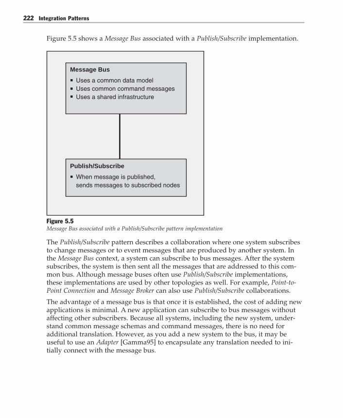
Integration Patterns222
Figure 5.5 shows a Message Bus associated with a Publish/Subscribe implementation.
Message Bus
Uses a common data modelUses common command messagesUses a shared infrastructure
Publish/Subscribe
When message is published, sends messages to subscribed nodes
Figure 5.5Message Bus associated with a Publish/Subscribe pattern implementation
The Publish/Subscribe pattern describes a collaboration where one system subscribesto change messages or to event messages that are produced by another system. Inthe Message Bus context, a system can subscribe to bus messages. After the systemsubscribes, the system is then sent all the messages that are addressed to this com-mon bus. Although message buses often use Publish/Subscribe implementations,these implementations are used by other topologies as well. For example, Point-to-Point Connection and Message Broker can also use Publish/Subscribe collaborations.
The advantage of a message bus is that once it is established, the cost of adding newapplications is minimal. A new application can subscribe to bus messages withoutaffecting other subscribers. Because all systems, including the new system, under-stand common message schemas and command messages, there is no need foradditional translation. However, as you add a new system to the bus, it may beuseful to use an Adapter [Gamma95] to encapsulate any translation needed to ini-tially connect with the message bus.

Chapter 5: Integration Topologies 223
The disadvantage of a message broker is the significant amount of work that isinvolved in creating common message schemas, command messages, and sharedinfrastructure within an enterprise. Because these systems typically cross organiza-tional boundaries and systems, gaining agreement on these key areas may be ex-tremely difficult, time consuming, or impossible.
Message Bus implementations vary significantly depending on the kind of Publish/Subscribe mechanism they employ. Because a Publish/Subscribe mechanism is such anintegral part of a Message Bus implementation, the next section looks at this patternmore closely.
Publish/SubscribeAt a high level, the Publish/Subscribe [Buschmann96] pattern helps keep cooperatingsystems synchronized by one-way propagation of messages because one publishersends a message to any number of intended subscribers. However, there are signifi-cant differences in the next level of design within the pattern. These differences leadto three refinements of the Publish/Subscribe pattern: List-Based Publish/Subscribe,Broadcast-Based Publish/Subscribe, and Content-Based Publish/Subscribe.
List-Based Publish/SubscribeA List-Based Publish/Subscribe pattern advises you to identify a subject and to main-tain a list of subscribers for that subject. When events occur, you have the subjectnotify each subscriber on the subscription list. A classic way to implement thisdesign is described in the Observer [Gamma95] pattern. When you use this pattern,you identify two classes: subjects and observers. Assuming you use a push modelupdate, you add three methods to the subject: Attach(), Detach(), and Notify(). Youadd one method to the observer — Update().
To use an observer, all interested observers register with the subject by using theAttach() method. As changes occur to the subject, the subject then calls each regis-tered observer by using the Notify() method. For a detailed explanation of theObserver pattern, see Design Patterns: Elements of Reusable Object-Oriented Software[Gamma95].
An observer works fine if you have created instances of objects that reify all yourobservers and subjects. An observer is especially well suited to situations where youhave one-to-many relationships between your subjects and your observers. How-ever, in the context of integration, you often have many observers that are linked tomany subjects, which complicates the basic Observer pattern. One way to implementthis many-to-many relationship is to create many subjects and to have each subjectcontain a list of observers.
Integration Patterns224
If you use this object structure to implement Publish/Subscribe, you must write theserelationships to persistent storage between process executions. To do so within arelational database, you must add an associative table to resolve the many-to-manydependencies between subject and observer. After you write this information topersistent storage in a set of tables, you can directly query the database for the list ofsubscribers for a topic.
Maintaining lists of published topics (subjects) and subscribers (observers) and thennotifying each one individually as events occur is the essence of List-Based Publish/Subscribe implementations. A very different means of achieving the same result is aBroadcast-Based Publish/Subscribe implementation.
Broadcast-Based Publish/SubscribeWhen you use a Broadcast-Based Publish/Subscribe approach [Tannebaum01, Oki93],an event publisher creates a message and broadcasts it to the local area network(LAN). A service on each listening node inspects the subject line. If the listeningnode matches the subject line to a subject that it subscribes to, the listening nodeprocesses the message. If the subject does not match, the listening node ignores themessage.
Subject lines are hierarchical and may contain multiple fields that are separated byperiods. Listening nodes that are interested in a particular subject can subscribe tothese fields by using wildcards, if required.
Although this Broadcast-Based Publish/Subscribe implementation is an effectivemethod for decoupling producers from consumers, it is sometimes useful to identifyparticular topic subscribers. To identify topic subscribers, a coordinating processsends a message that asks listening nodes to reply if they subscribe to a particulartopic. Responses are then returned by each listening node to the provider to identifythe subscribers.
Because all messages are sent to all listening nodes, and because each node is re-sponsible for filtering unwanted messages, some authors refer to this as a publish/subscribe channel with reactive filtering [Hohpe04].
Content-Based Publish/SubscribeBoth Broadcast-Based Publish/Subscribe implementations and List-Based Publish/Subscribe implementations can be broadly categorized as topic-based because theyboth use predefined subjects as many-to-many channels. Publish/Subscribe imple-mentations have recently evolved to include a new form — Content-Based Publish/Subscribe. The difference between topic-based and content-based approaches is asfollows:
Chapter 5: Integration Topologies 225
In a topic-based system, processes exchange information through a set of pre-defined subjects (topics) which represent many-to-many distinct (and fixed)logical channels. Content-based systems are more flexible as subscriptions arerelated to specific information content and, therefore, each combination of infor-mation items can actually be seen as a single dynamic logical channel. Thisexponential enlargement of potential logical channels has changed the way toimplement a pub/sub system. [Baldoni03]
The practical implication of this approach is that messages are intelligently routed totheir final destination based on the content of the message. This approach over-comes the limitation of a broadcast-based system, where distribution is coupled to amulticast tree that is based on Transmission Control Protocol (TCP). It also gives theintegration architect a great deal of flexibility when deciding on content-basedrouting logic.
A More Detailed Look at TopologiesTo fully understand how collaborations that are based on Point-to-Point Connection,Broker, and Message Bus work together with other parts of your technical architec-ture, it is useful to view your system’s topologies from three discrete topologylevels: physical, logical, and integration.
Note: This section discusses low-level layers of the Open Systems Interconnection (OSI) stack.It then moves on to discuss the top layer (Application), bypassing many important layers. Thisis intentional because this section only discusses the relationship between these low-levellayers and the integration topology pattern choices. It does not mean that these layers are notimportant. However, they are not architecturally significant for this particular discussion.
Topology LevelsBecause the terms point-to-point, bus, and hub were first defined at the physicallevel, this section starts with a review of the physical network topology level. Inaddition to a physical connection, you also need a logical communication protocol.That logical communication protocol also implies a topology. After logical andphysical topology levels are established, it is possible to establish patterns of com-munication between the collaborating nodes. These patterns of communication andcollaboration form an integration topology level that is described by the Point-to-Point Connection, the Broker, and the Message Bus patterns.
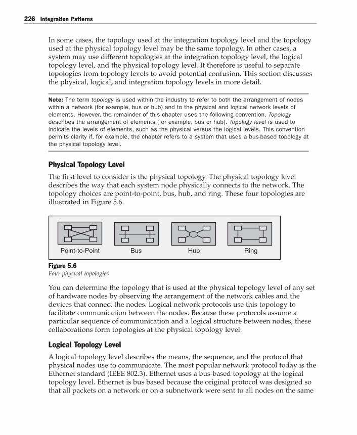
Integration Patterns226
In some cases, the topology used at the integration topology level and the topologyused at the physical topology level may be the same topology. In other cases, asystem may use different topologies at the integration topology level, the logicaltopology level, and the physical topology level. It therefore is useful to separatetopologies from topology levels to avoid potential confusion. This section discussesthe physical, logical, and integration topology levels in more detail.
Note: The term topology is used within the industry to refer to both the arrangement of nodeswithin a network (for example, bus or hub) and to the physical and logical network levels ofelements. However, the remainder of this chapter uses the following convention. Topologydescribes the arrangement of elements (for example, bus or hub). Topology level is used toindicate the levels of elements, such as the physical versus the logical levels. This conventionpermits clarity if, for example, the chapter refers to a system that uses a bus-based topology atthe physical topology level.
Physical Topology LevelThe first level to consider is the physical topology. The physical topology leveldescribes the way that each system node physically connects to the network. Thetopology choices are point-to-point, bus, hub, and ring. These four topologies areillustrated in Figure 5.6.
Point-to-Point Bus Hub Ring
Figure 5.6Four physical topologies
You can determine the topology that is used at the physical topology level of any setof hardware nodes by observing the arrangement of the network cables and thedevices that connect the nodes. Logical network protocols use this topology tofacilitate communication between the nodes. Because these protocols assume aparticular sequence of communication and a logical structure between nodes, thesecollaborations form topologies at the physical topology level.
Logical Topology LevelA logical topology level describes the means, the sequence, and the protocol thatphysical nodes use to communicate. The most popular network protocol today is theEthernet standard (IEEE 802.3). Ethernet uses a bus-based topology at the logicaltopology level. Ethernet is bus based because the original protocol was designed sothat all packets on a network or on a subnetwork were sent to all nodes on the same

Chapter 5: Integration Topologies 227
network segment. This configuration requires each listening node to filter unwantedpackets. The protocol provides for collisions that may occur if more than one nodetransmits simultaneously. Since the original protocol was developed, advances innetwork hardware have enabled devices to route messages to selected nodes toimprove performance. One such advance is the development of switches. TheEthernet protocol also has evolved to take advantage of these developments, but itstill supports a bus-based logical topology.
A less-used network protocol is token passing (IEEE 802.5). Token passing uses aring-based topology at the logical topology level. With this topology, each nodeconnects to the next node in the ring and passes a message in a circular fashion untilit arrives at the intended destination.
As shown in Figure 5.7, the topology of the logical topology level and the topologyof the physical topology level correspond exactly in some cases.
PhysicalTopology
Point-to-Point Bus Hub
Mapping
Ring
Logical Topology
Point-to-Point Bus Hub Ring
Figure 5.7Direct mapping of topologies at the logical and physical topology levels
For example, a set of nodes that are connected with a bus-based topology at thephysical topology level might also be connected with a bus-based topology at thelogical topology level. This topology is the topology that often exists when you usethe Ethernet protocol. Or, a set of nodes that are connected with a ring-based topol-ogy at the physical topology level might also be connected with a ring-based topol-ogy at the logical topology level. This is the topology that exists when you use tokenpassing. However, it is important to understand that the topologies used at thephysical and logical topology levels do not have to be the same. In practice, they areoften different.
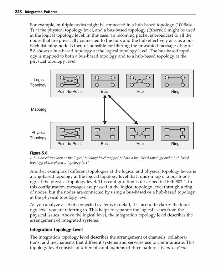
Integration Patterns228
For example, multiple nodes might be connected in a hub-based topology (100Base-T) at the physical topology level, and a bus-based topology (Ethernet) might be usedat the logical topology level. In this case, an incoming packet is broadcast to all thenodes that are physically connected to the hub, and the hub effectively acts as a bus.Each listening node is then responsible for filtering the unwanted messages. Figure5.8 shows a bus-based topology at the logical topology level. The bus-based topol-ogy is mapped to both a bus-based topology and to a hub-based topology at thephysical topology level.
PhysicalTopology
Logical Topology
Point-to-Point Bus Hub Ring
Point-to-Point Bus Hub
Mapping
Ring
Figure 5.8A bus-based topology at the logical topology level mapped to both a bus-based topology and a hub-basedtopology at the physical topology level
Another example of different topologies at the logical and physical topology levels isa ring-based topology at the logical topology level that runs on top of a bus topol-ogy at the physical topology level. This configuration is described in IEEE 802.4. Inthis configuration, messages are passed in the logical topology level through a ringof nodes, but the nodes are connected by using a bus-based or a hub-based topologyat the physical topology level.
As you analyze a set of connected systems in detail, it is useful to clarify the topol-ogy level you are referring to. This helps to separate the logical issues from thephysical issues. Above the logical level, the integration topology level describes thearrangement of integrated systems.
Integration Topology LevelThe integration topology level describes the arrangement of channels, collabora-tions, and mechanisms that different systems and services use to communicate. Thistopology level consists of different combinations of three patterns: Point-to-Point

Chapter 5: Integration Topologies 229
Connection, Broker, and Message Bus. These patterns, along with the related Publish/Subscribe pattern, are illustrated in Figure 5.9 by using circles.
IntegrationPatterns
List-BasedPublish/Subscribe
Broadcast-BasedPublish/Subscribe
Publish/Subscribe
Content-BasedPublish/Subscribe
DirectBroker
IndirectBroker
Point-to-PointConnection
A pattern refinement
Message Bus
Broker
Bus HubPoint-to-Point
MessageBroker
Figure 5.9Integration patterns related to topologies
Now let’s look at how integration topologies interact with logical and physicaltopologies in more detail.
Using Topologies TogetherTo design an integration architecture, you must decide on high-level collaborationsin the integration topology level. These collaborations use other combinations ofcollaborations and topologies in the logical topology level. In turn, these collabora-tions use, and in some situations are constrained by, the topologies used in the

Integration Patterns230
physical topology level. Note that each level has its own set of concerns and respon-sibilities. Let’s now look at these collaborations in more detail.
Point-to-Point ConnectionFigure 5.10 shows how to implement the Point-to-Point Connection pattern. Given thepopularity of Ethernet, point-to-point connections are often connected by a bus inthe logical topology level. Using common network devices like routers, hubs, andswitches, the physical topology level is usually either hub based or bus based.Regardless of the topologies used at the physical and logical topology levels, froman integration pattern perspective, the nodes are using a Point-to-Point Connectionpattern if both of the following are true:● Exactly one message is sent to and received by one target node.● The responsibility for determining the target location and protocol lies with the
sender.
PhysicalTopology
Point-to-Point Bus Hub
IntegrationTopology
Logical Topology
Point-to-Point Bus Hub
Point-to-Point Connection
Figure 5.10Topologies stack for a Point-to-Point Connection integration pattern

Chapter 5: Integration Topologies 231
Breaking these topologies into discrete levels lets you qualify topology discussionsby using a frame of reference. For example, using the configuration that is shown inFigure 5.10, you might have a Point-to-Point Connection topology at the integrationtopology level that is connected to a bus topology at the logical topology level andto a bus or hub topology at the physical topology level.
BrokerThe collaboration described in the Broker pattern uses a combination of many othertopologies. For example, let’s review the CORBA direct broker example that isdiscussed earlier in this chapter.
“Upon startup, an object request broker (ORB) acting as a client sends a UDP broadcaston its local subnet to find a naming service.”
Here, a broker uses a bus topology at the logical topology level to send a broadcastto all the systems that are connected to its subnet. In this case, the topology used atthe physical topology level is irrelevant, but it is likely to be hub based or bus baseddue to the ubiquity of Ethernet. Note that the naming service must be located on thesame subnet as the ORB for this scheme to work.
“Using this naming service, the ORB requests the location of the target server on behalf ofthe client.”
This is a standard broker collaboration. The main requirement here is that the sourcesystem be able to connect point-to-point with the naming service. Therefore, thetopologies used at the logical and physical topology levels are less important. Again,due to the ubiquity of Ethernet, the topology used at the logical topology level islikely to be bus based, but the topology used at the physical topology level is likelyto be either hub based or bus based.
“All subsequent communication occurs directly between the client proxy and the serverproxy by using a point-to-point connection.”
Again, the main requirement is that the source system be able to connect point-to-point to the target. This also is likely to be a bus topology at the logical topologylevel and a hub or bus topology at the physical topology level.
Although the Broker collaboration may have some amount of coupling to underlyingtopologies at both the physical and logical topology levels, the amount of couplingis much more pronounced when you use Message Bus in conjunction with a Publish/Subscribe implementation.
Message Bus and Publish/SubscribeMessage Bus implementations can vary greatly depending on the Publish/Subscribemechanism that they employ. Now let’s examine the practical implications of usingthe three Publish/Subscribe variations together with Message Bus.

Integration Patterns232
Message Bus with Broadcast-Based Publish/SubscribeTo use a Message Bus implementation that contains a Broadcast-Based Publish/Subscribe implementation, a system sends a command message to the message bus.The message bus broadcasts the message to all the nodes that are listening to thebus. The message bus makes no attempt to determine the appropriate subscribers.Instead, each listening node filters any unwanted messages and processes only themessages that it is interested in. Any data associated with the messages is in acommon format so that all systems can interpret the command message and thedata, and then respond appropriately.
From a topology perspective, this combination of the Message Bus pattern and thePublish/Subscribe patterns uses a bus-based topology at the logical topology level(Ethernet) to make a bus-based broadcast communication from the message bus toall the listening nodes. The physical topology at this point is irrelevant, but it isusually either hub based or bus based.
Message Bus with List-Based Publish/SubscribeTo use a message bus that contains a List-Based Publish/Subscribe implementation, asystem sends a command message to the message bus. The message bus then looksup all interested bus subscribers and sends each one a copy of the original message.Any data associated with the message is in a common format so that all systems caninterpret the command message and the data, and then respond appropriately.
From a topology perspective, this combination of the Message Bus and Publish/Subscribe patterns is likely to use (but not to be coupled to) a bus topology at thelogical topology level (Ethernet) to make point-to-point connections from the mes-sage bus to the subscribing nodes, as shown in Figure 5.11. At this point, the topol-ogy used at the physical topology level is irrelevant, but it is usually either hubbased or bus based.

Chapter 5: Integration Topologies 233
PhysicalTopology
Point-to-Point Bus Hub
IntegrationTopology
Logical Topology
Point-to-Point Bus Hub
Message Bus
Figure 5.11A message bus using a bus topology at the logical topology level and a bus or hub topology at thephysical topology level

Integration Patterns234
Message Bus with Content-Based Publish/SubscribeTo use a Message Bus pattern that contains a Content-Based Publish/Subscribe imple-mentation, a system sends a command message to the message bus. After the mes-sage bus receives the message, it is responsible for matching the message against aset of subscribers. The message bus then forwards the message to each of the appro-priate subscribers.
To match the message against a set of subscribers, the message bus must determineif there are any subscribers interested in this particular message. If an interestedsubscriber exists, the subscriber matches a particular message field or fields and aset of values. If a match exists between the message content and a subscriber, themessage is then forwarded to each matching subscriber.
After a subscribing system receives a bus message, the subscribing system is able toprocess the message because the message contains the common command messageand the agreed-upon message schemas.
Although the Message Bus using List-Based Publish/Subscribe and the Message Bususing Content-Based Publish/Subscribe patterns both check for subscriptions beforeforwarding messages, there are key differences. The list-based approach matchessubscriptions on subjects. The content-based approach allows you to identify one ormore fields in the message and to identify a set of acceptable values for each field.As a result, you can create very intelligent routing capabilities. This makes thecontent-based approach more flexible than the list-based approach.
To make Content-Based Publish/Subscribe work, you need a high performance infra-structure component that can read each message, query a set of potential subscrib-ers, and efficiently route the message to each subscriber. In practice, you can think ofthis as a message switch. This is exactly how Microsoft BizTalk Server 2004 is de-signed.
Figure 5.12 shows the Message Bus pattern using a Publish/Subscribe pattern or one ofthe Publish/Subscribe variants.
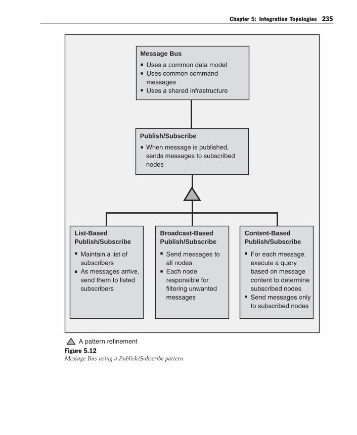
Chapter 5: Integration Topologies 235
Message Bus
Uses a common data modelUses common command messagesUses a shared infrastructure
List-Based Publish/Subscribe
Maintain a list of subscribersAs messages arrive, send them to listed subscribers
Publish/Subscribe
When message is published, sends messages to subscribed nodes
Broadcast-Based Publish/Subscribe
Send messages toall nodesEach noderesponsible for filtering unwanted messages
Content-Based Publish/Subscribe
For each message,execute a query based on messagecontent to determinesubscribed nodesSend messages only to subscribed nodes
A pattern refinement
Figure 5.12Message Bus using a Publish/Subscribe pattern

Integration Patterns236
Integration Topology Level PatternsThe following table summarizes the integration patterns that are discussed in thischapter.
Table 5.1: Integration Network Patterns
Pattern Problem Associated implementations
Message Broker How do you integrate applications Implementing Message Brokerwithout enforcing a common interface with BizTalk 2004and also allow each application toinitiate interactions with severalother applications?
Message Bus As an integration solution grows,how can you lower the cost of addingor removing applications?
Publish/Subscribe How can an application in anintegration architecture only sendmessages to the applications that areinterested in receiving the messageswithout knowing the identities ofthe receivers?
Chapter 5: Integration Topologies 237
Message Broker
AliasesHub and Spoke
ContextYou have an online store that integrates several systems, such as the Web-basedfront-end system, the credit card verification system, the retail system, and theshipping system. The control flow usually originates in the front end. For example, acustomer placing an order causes the online store to send a request message to thecredit card verification system. If the credit card information is validated, the onlinestore sends request messages to the various retail systems, depending on the or-dered items. An order for books translates into a purchase order message for thebook retailer; an order for electronics translates into a purchase order message forthe electronics retailer; and an order for gardening supplies translates into a pur-chase order message for the home and garden supplier.
The control flow could also originate in a retail or shipping system. For example,when a retailer updates a catalog, the retail system sends catalog update messages tothe store so that the store can display the new items. When a shipper changes theshipping rates, the shipping system sends a rate update message to the store so thatthe store can compute the correct shipping charges. Similarly, when a shipperchanges pickup times, the shipping system sends update messages to all the retailersthe system serves so that they can have the shipments ready in time.
ProblemHow do you integrate applications without enforcing a common interface and alsoallow each application to initiate interactions with several other applications?
ForcesTo integrate applications without changing their interfaces, you must balance thefollowing forces:● Point-to-point integration requires a large number of connections between appli-
cations. Many connections usually translate into many interfaces.● Message Bus integration facilitates adding new applications, but it requires a
common bus interface. Because integration solutions usually involve applicationsthat have proprietary interfaces provided by multiple vendors, Message Busintegration is difficult.

Integration Patterns238
● Run-time control of qualities such as availability and performance may requiredynamic reconfiguration.
● The applications in an integration solution could have conflicting quality ofservice (QoS) requirements.
● The applications in an integration solution could belong to different securityrealms.
SolutionExtend the integration solution by using Message Broker. A message broker is aphysical component that handles the communication between applications. Insteadof communicating with each other, applications communicate only with the messagebroker. An application sends a message to the message broker, providing the logicalname of the receivers. The message broker looks up applications registered underthe logical name and then passes the message to them.
Communication between applications involves only the sender, the message broker,and the designated receivers. The message broker does not send the message to anyother applications. From a control-flow perspective, the configuration is symmetricbecause the message broker does not restrict the applications that can initiate calls.Figure 5.13 illustrates this configuration.
Application 1
Application 2 Message Broker
Application 4
Application 5Application 3
Figure 5.13A message broker mediating the collaboration between participating applications
The message broker can expose different interfaces to the collaborating applications,and it can translate messages between these interfaces. In other words, the messagebroker does not enforce a common interface on the applications.

Chapter 5: Integration Topologies 239
Prior to using a message broker, you must register the applications that receivecommunications so that the message broker can dispatch requests to them. Themessage broker may provide its own registration mechanism, or it may rely on anexternal service such as a directory.
Placing the message broker between the sender and the receiver provides flexibility inseveral ways. First, the message broker allows the integration solution to dynamicallychange its configuration. For example, if an application must be shut down for main-tenance, the message broker could start routing requests to a failover application.Likewise, if the receiver cannot keep up with the incoming messages, the messagebroker could start load balancing between several receivers.
Second, the message broker can choose between applications that have different QoSlevels. This resembles the dynamic configuration, but the message broker selects theapplication based on specified criteria. For example, an application for premiumaccounts may fulfill requests quickly, but an application for general use may have alonger processing time.
Third, the message broker allows the sender and the receiver to reside in differentsecurity realms. In other words, the message broker can reside on the boundarybetween two security realms and bridge requests between those two realms. Table5.2 shows the responsibilities and collaborations of a message broker.
Table 5.2: Message Broker Responsibilities and Collaborations
Responsibilities Collaborations
– Receive message – Senders: applications that send messages – Determine the message recipients to the message brokerand perform the routing – Receivers: applications that receive – Handle any interface-level differences messages from the message broker – Send the message to the recipients
ExampleConsider an online store that allows shoppers to browse a variety of retail catalogsand to place orders. When an order is placed, the online store groups the shoppingcart items by retailer and places appropriate orders with each retailer. As eachretailer fulfills and ships the order, it sends the online store a tracking number. Theonline store updates its records so that this information is presented on the CheckOrder Status page. If the customer has configured e-mail alerts, the store also sendsan e-mail message that contains the tracking information.
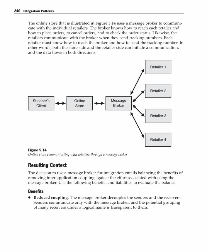
Integration Patterns240
The online store that is illustrated in Figure 5.14 uses a message broker to communi-cate with the individual retailers. The broker knows how to reach each retailer andhow to place orders, to cancel orders, and to check the order status. Likewise, theretailers communicate with the broker when they send tracking numbers. Eachretailer must know how to reach the broker and how to send the tracking number. Inother words, both the store side and the retailer side can initiate a communication,and the data flows in both directions.
Retailer 1
Retailer 2
Retailer 3
Message Broker
OnlineStore
Shopper’sClient
Retailer 4
Figure 5.14Online store communicating with retailers through a message broker
Resulting ContextThe decision to use a message broker for integration entails balancing the benefits ofremoving inter-application coupling against the effort associated with using themessage broker. Use the following benefits and liabilities to evaluate the balance:
Benefits● Reduced coupling. The message broker decouples the senders and the receivers.
Senders communicate only with the message broker, and the potential groupingof many receivers under a logical name is transparent to them.
Chapter 5: Integration Topologies 241
● Improved integrability. The applications that communicate with the messagebroker do not need to have the same interface. Unlike integration through a bus,the message broker can handle interface-level differences. In addition, the mes-sage broker can also act as a bridge between applications that are from differentsecurity realms and that have different QoS levels.
● Improved modifiability. The message broker shields the components of theintegration solution from changes in individual applications. It also enables theintegration solution to change its configuration dynamically.
● Improved security. Communication between applications involves only thesender, the broker, and the receivers. Other applications do not receive the mes-sages that these three exchange. Unlike bus-based integration, applicationscommunicate directly in a manner that protects the information without the useof encryption.
● Improved testability. The message broker provides a single point for mocking.Mocking facilitates the testing of individual applications as well as of the interac-tion between them.
Liabilities● Increased complexity. Communicating through a message broker is more com-
plex than direct communication for the following reasons:● The message broker must communicate with all the parties involved. This
could mean providing many interfaces and supporting many protocols.● The message broker is likely to be multithreaded, which makes it hard to trace
problems.● Increased maintenance effort. Broker-based integration requires that the integra-
tion solution register the applications with the broker. Bus-based integration doesnot have this requirement.
● Reduced availability. A single component that mediates communication betweenapplications is a single point of failure. A secondary message broker could solvethis problem. However, a secondary message broker adds the issues that areassociated with synchronizing the states between the primary message brokerand the secondary message broker.
● Reduced performance. The message broker adds an intermediate hop and incursoverhead. This overhead may eliminate a message broker as a feasible option forsolutions where fast message exchange is critical.
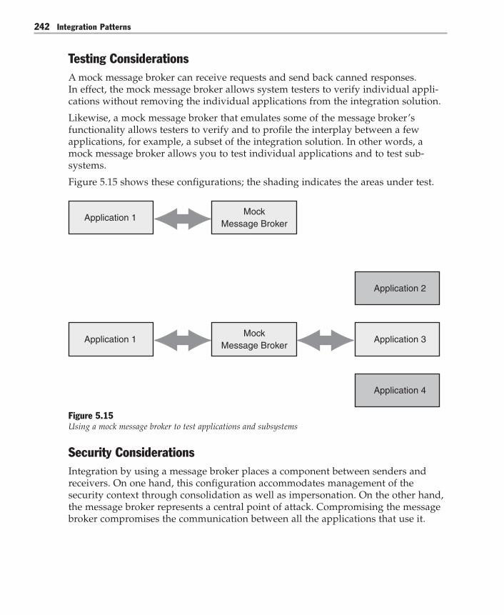
Integration Patterns242
Testing ConsiderationsA mock message broker can receive requests and send back canned responses.In effect, the mock message broker allows system testers to verify individual appli-cations without removing the individual applications from the integration solution.
Likewise, a mock message broker that emulates some of the message broker’sfunctionality allows testers to verify and to profile the interplay between a fewapplications, for example, a subset of the integration solution. In other words, amock message broker allows you to test individual applications and to test sub-systems.
Figure 5.15 shows these configurations; the shading indicates the areas under test.
Application 1Mock
Message Broker
Application 1 Application 3
Application 2
Application 4
Mock Message Broker
Figure 5.15Using a mock message broker to test applications and subsystems
Security ConsiderationsIntegration by using a message broker places a component between senders andreceivers. On one hand, this configuration accommodates management of thesecurity context through consolidation as well as impersonation. On the other hand,the message broker represents a central point of attack. Compromising the messagebroker compromises the communication between all the applications that use it.

Chapter 5: Integration Topologies 243
Operational ConsiderationsThe message broker can dynamically change the configuration. It can direct mes-sages to a failover application if necessary or perform load balancing betweenapplications, or the message broker can do both.
Known UsesBroker-based integration products such as Microsoft BizTalk Server 2004 extend thetraditional broker functionality with additional features. For example, BizTalk Server2004 provides orchestration services, messaging services, and other features associ-ated with these services such as business activity monitoring, transaction andexception handling, correlation, and graphic editing.
VariantsA message broker variant trades ease of integration for performance. The perfor-mance-optimized message broker looks up the receiver and then connects it to thesender, thus allowing the sender and the receiver to communicate directly. Thedirect connection eliminates the performance penalty that is associated with anintermediary between the communicating parties. However, this performanceoptimization only works if the sender and the receiver have the same interface.
Related PatternsFor more information, see the following related patterns:● Broker [Buschmann96]. In a distributed setting, the Broker pattern tries to make
distribution transparent. Client-side and server-side proxies mediate between thebroker and the clients and server.
● Implementing Message Broker with BizTalk Server 2004. This pattern uses the GlobalBank scenario to show how you can use BizTalk Server 2004 to implement Mes-sage Broker.
● Client-Dispatcher-Server [Buschmann96]. The Client-Dispatcher-Server pattern is aBroker variant that uses the direct communication optimization mentioned earlierin “Variants.”
● Content-Based Router [Hohpe04]. The Content-Based Router pattern is a Brokervariant that specializes in routing communications to different applications basedon the content of the communication.
● Mediator [Gamma95]. The Mediator pattern separates objects so that they are onlyaware of the mediator but not each other. The Broker deals with similar concerns,but it can only be used in the context of enterprise applications.

Integration Patterns244
Acknowledgments[Buschmann96] Buschmann, Frank; Regine Meunier, Hans Rohnert, PeterSommerlad, and Michael Stal. Pattern-Oriented Software Architecture, Volume 1: ASystem of Patterns. John Wiley & Sons Ltd, 1996.
[Gamma95] Gamma, Erich; Richard Helm, Ralph Johnson, and John Vlissides.Design Patterns: Elements of Reusable Object-Oriented Software. Addison-Wesley, 1995.
[Hohpe04] Hohpe, Gregor, and Bobby Woolf. Enterprise Integration Patterns: Design-ing, Building and Deploying Messaging Solutions. Addison-Wesley, 2004.
[Trowbridge03] Trowbridge, David; Dave Mancini, Dave Quick, Gregor Hohpe,James Newkirk, and David Lavigne. Enterprise Solution Patterns Using Microsoft.NET. Microsoft Press, 2003. Also available on the MSDN Architecture Center at:http://msdn.microsoft.com/architecture/patterns/default.aspx?pull=/library/en-us/dnpatterns/html/Esp.asp.

Chapter 5: Integration Topologies 245
Implementing Message Broker with BizTalk Server 2004
ContextYour application is interacting with multiple other applications through a MessageBroker so that each application only needs to communicate with the Message Broker,rather than all the other applications. The Message Broker is implemented by usingMicrosoft BizTalk Server 2004.
BackgroundGlobal Bank is implementing an Execute Scheduled Payment business process thatcustomers can use to schedule payments. Each payment is transacted through apayment authority. The payment authority is determined when that payee is firstconfigured. Currently, there are three different payment authorities:● There is an internal payment authority that Global Bank uses to handle payments
itself.● There is an external payment authority where payment requests are sent to an
external bill payment authority.● There is a manual payment authority where payment requests are handled
manually.
Bank growth, acquisitions, and mergers may increase the number of paymentauthorities.
To implement the Execute Scheduled Payment business process, Global Bank choseto use Microsoft BizTalk Server 2004 as an implementation of the Message Brokerpattern. As Figure 5.16 shows, requests for payment are sent directly to the messagebroker, and the message broker then sends the request to the correct paymentauthority.

Integration Patterns246
Internal PaymentAuthority
Global BankExternal Payment
Authority
Manual PaymentAuthority
Message Broker: BizTalk Server 2004
Figure 5.16BizTalk Server 2004 as Message Broker in Global Bank
Apart from sending any message received to the appropriate recipient, the MessageBroker implementation also must do the following:● The implementation must parse the message to determine where to send it.● The implementation must convert the message from the source format to the
destination format.● The implementation must allow receivers (applications) to register with the
broker so that the broker can send messages to them.
Implementation StrategyBizTalk Server 2004 uses a Publish/Subscribe messaging architecture that can easily beused to implement Message Broker. BizTalk Server 2004 uses Pipes and Filters for themessage transformation.
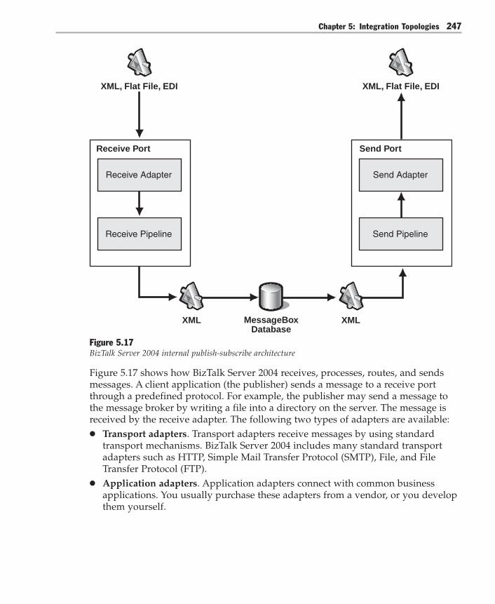
Chapter 5: Integration Topologies 247
Receive Port
Receive Adapter
Receive Pipeline
XML, Flat File, EDI
MessageBoxDatabase
Send Port
Send Adapter
Send Pipeline
XML, Flat File, EDI
XML XML
Figure 5.17BizTalk Server 2004 internal publish-subscribe architecture
Figure 5.17 shows how BizTalk Server 2004 receives, processes, routes, and sendsmessages. A client application (the publisher) sends a message to a receive portthrough a predefined protocol. For example, the publisher may send a message tothe message broker by writing a file into a directory on the server. The message isreceived by the receive adapter. The following two types of adapters are available:● Transport adapters. Transport adapters receive messages by using standard
transport mechanisms. BizTalk Server 2004 includes many standard transportadapters such as HTTP, Simple Mail Transfer Protocol (SMTP), File, and FileTransfer Protocol (FTP).
● Application adapters. Application adapters connect with common businessapplications. You usually purchase these adapters from a vendor, or you developthem yourself.

Integration Patterns248
The receive adapter passes the message to a receive pipeline, and the receivepipeline then parses and converts the incoming message to XML (except when usingthe pass-through pipeline). XML is the format that BizTalk Server 2004 usesinternally. As the receive adapter receives the message and as the receive pipelineprocesses it, additional data about the message is collected. This message metadataincludes information about the transport the message was received on, such as theoriginal name of the file in the case of a file transport. It also includes informationfrom each of the components in the pipeline. For example, the Party Resolutioncomponent stores information it receives from a digital certificate attached to themessage. This metadata is known as the context properties.
The receive pipeline uses an XML schema that the developer created. This schemadisassembles and converts the message to XML and then validates the messageagainst the schema specification. The schema describes the type, the cardinality, andthe other attributes of every record and every field that is contained in the message.As the receive pipeline parses the message, it collects data from within the messageitself. To do this, the developer creates a second schema that is known as a propertyschema. The property schema allows specific portions of the message to be promotedas additional metadata. This metadata is known as the promoted properties. For anexample of how promotion occurs, see the “Example” section later in this pattern.After preprocessing in the receive pipeline, the message is submitted to theMessageBox database complete with all additional metadata.
The MessageBox database sends the message to the message recipients by using amessage subscription. To implement a message subscription, the developer creates asend port that represents the message recipient. A send port usually consists of asend pipeline for post-processing of the message, a send adapter that transmits themessage to its destination, and a filter expression that defines whether the messagewill be sent through this send port. The filter expression is a query against thecontext properties of messages in the MessageBox database. A copy of the messageis only sent to this send port if there is a match between the filter expression and thecontext properties. For example, the filter expression on the send port might state,“send all documents that are of type ExecutePayment.Payment, where the fulfillmentTypeIdis equal to 1.”
The MessageBox database sends a copy of the messages to each send port that has afilter expression that matches the context properties. The message is received by thesend port (the subscriber process), processed by the send pipeline, and thentransmitted through the send adapter. The send adapter can be a transport adaptersuch as File, FTP, HTTP, BizTalk Message Queuing (MSMQT), SMTP, SOAP, orMQSeries. Or, the send adapter can be an application adapter that connects directlyto the destination application.
To implement the Message Broker, the Global Bank developer must do the following:
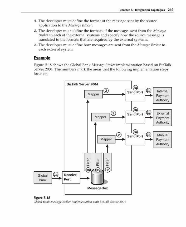
Chapter 5: Integration Topologies 249
1. The developer must define the format of the message sent by the sourceapplication to the Message Broker.
2. The developer must define the formats of the messages sent from the MessageBroker to each of the external systems and specify how the source message istranslated to the formats that are required by the external systems.
3. The developer must define how messages are sent from the Message Broker toeach external system.
ExampleFigure 5.18 shows the Global Bank Message Broker implementation based on BizTalkServer 2004. The numbers mark the areas that the following implementation stepsfocus on.
MessageBox
BizTalk Server 2004
GlobalBank
Mapper
Mapper
Mapper
Filt
er
Filt
er
Filt
er
Send Port
Send Port
Send Port
InternalPaymentAuthority
ExternalPaymentAuthority
ManualPaymentAuthority
1b
1b
1b
3a
3a
3a
2
2
2
1a3b3b3b
ReceivePort
Figure 5.18Global Bank Message Broker implementation with BizTalk Server 2004

Integration Patterns250
Step 1: Create the Receive Port and Define Message SchemasThe first step in the implementation of the Message Broker is to create the receive portin BizTalk Explorer. This receive port defines the location that the client applicationwill send messages to so that the messages are published to the message broker.Virtually any transport can be used to send messages from the client to the messagebroker. This example uses the BizTalk Message Queuing (MSMQT) adapter becauseMSMQT provides guaranteed delivery.
� To create the receive port for the message broker1. Create a receive port called Payment Broker RP.2. Create a receive location on this receive port called Payment Broker RL.3. Set the transport for the receive location to MSMQT with a queue named
Payments.4. Specify the BizTalkServerApplication as the receive handler, and specify XML
Receive as the receive pipeline.5. After following the remaining steps to implement the message broker, enable the
receive location.
This completes the creation of the receive port.
Next, the payment messages sent by Global Bank and the messages going to each ofthe three payment channels have to be defined. The payment messages are marked1a in Figure 5.18, and the payment channels are marked 1b. BizTalk Server usesthese definitions (XML schemas) to parse and to convert messages into XML if theyare not already in XML. A disassembler component in the receive pipeline parsesand converts these messages.
For the Execute Scheduled Payment implementation, the schema is actuallygenerated automatically by the SQL Transport Schema Generation Wizard (seeImplementing Process Integration with BizTalk Server 2004). Figure 5.19 shows thegenerated schema in the BizTalk Server Schema Editor.

Chapter 5: Integration Topologies 251
Figure 5.19The Payment schema in the BizTalk Server 2000 Schema Editor
You can also create a special second schema that is known as a property schema. Thisproperty schema defines one or more fields that are linked to specific fields in themessage schema. Linking fields in this way is known as promoting properties. Thislink between the message schema and the property schema is established in thePromote Properties dialog box in the BizTalk Server Schema Editor. In Figure 5.19,the unique symbol next to the fulfillmentTypeId field denotes a promoted propertyfield.
Figure 5.20 shows the Promote Properties dialog box where you promotethe fulfillmentTypeId field that is in the payment message. The value of thefulfillmentTypeId field is used later to determine the payment authority that themessage is sent to.

Integration Patterns252
Figure 5.20Creating a promoted property field
The format of the message that is sent to the message broker is specified by the XMLschema shown in Figure 5.19. The format of the messages for each of the paymentauthorities is likely to be different from the source format. The format of the mes-sages is also likely to vary between different payment authorities. Therefore, schemadefinitions for each of the outgoing message formats also have to be built. Forbrevity, these schema definitions are not presented here.
Step 2: Define Maps to Convert Between Message FormatsFor each of the destination message formats specified in the previous section, anXSLT map must be developed. This XSLT map specifies how the source messageformat is translated to the destination message format (number 2 in Figure 5.18).These message format translations may be merely structural. For example, converting an XML message to a comma-separated-values (CSV) message is struc-tural. Or, the translation may require the generation of new message content. Forexample, the source message may not contain any information about the time ordate that the message was sent, but this information may be required in the destina-tion format. New message content also has to be generated when a field in thesource message is used as a key to a specific row in a database table, and fields inthe destination message are filled from fields in this database row. This is a commonrequirement.

Chapter 5: Integration Topologies 253
Figure 5.21Payment authority map in the BizTalk Mapper
You can use the BizTalk Mapper to create the XSLT maps. The BizTalk Mapperprovides a graphical view of source and destination schemas and of the conversionfrom one to the other. The output from the BizTalk Mapper is the XSLT map. Figure5.21 shows the development of a payment authority map from the source XMLschema in the BizTalk Mapper. Three separate maps are created, one for each of thepayment authorities:● PaymentRequest2InternalPayee.btm is created for the internal payee.● PaymentRequest2ExternalPayee.btm is created for the external payee.● PaymentRequest2ManualPayee.btm is created for the manual payee.
Step 3: Create Subscriptions to MessagesTo configure the BizTalk Server message broker for the Execute Scheduled Paymentscenario, three send ports must be configured. Each send port is configured with itsown specific transport type and transport address, send pipeline, and BizTalk map(number 3a in Figure 5.18). In addition, the port filter has to be specified appropri-ately on each send port to set up the correct subscription for this payment authorityto the MessageBox database (number 3b in Figure 5.18).
� To configure one of the send ports (Internal Payment)1. Create a new send port that is called InternalPayee_SP.2. Select SOAP (Web Services) for the transport type. Use the following as the
transport address (the Uniform Resource Identifier [URI]):http://EAIPayee/InternalPayee/Payee.asmx
Depending on the transport chosen, different transport address information canbe specified.

Integration Patterns254
3. Specify XML Pipeline as the send pipeline. The send pipeline defines the post-processing that is performed on the message just before the message is sent, suchas attachment of a digital signature to the message.
4. Specify PaymentRequest2InternalPayee.btm as the XSLT map to be applied tothe source messages.
5. Specify the filters for this send port. These filters define the subscription for thissend port in the MessageBox database, and they control the criteria that theMessageBox database uses to determine the messages that are sent to this port.For the Execute Scheduled Payment scenario, the filter specifies the followingtwo criteria as shown in Figure 5.22:● All messages of type http://GlobalBank#payment.● Messages that have a promoted fulfillmentTypeId property that is equal to 1
(internal fulfillment).
Figure 5.22Specifying the filter (subscription) for a send port

Chapter 5: Integration Topologies 255
With this configuration, all messages of type http://GlobalBank#payment that havea fulfillmentTypeId property that is set to 1 (internal fulfillment) are sent to thissend port. This send port is configured to transmit the payment authorization tothe internal payment application by using a SOAP call.
6. Configure the remaining ports in a similar way. Each port has its own uniquetransport address and its own unique XSLT map. In addition, the filters on thesetwo ports specify a different value for the fulfillmentTypeId property.A value of 2 denotes external fulfillment, and a value of 3 denotes manualfulfillment.
7. Finally, enlist and then start each of the send ports.
Resulting ContextThe implementation of the Message Broker pattern with BizTalk Server 2004 results inthe following benefits and liabilities:
Benefits● Message routing is determined at run time. Destination applications can be
added or deleted from the system at run time without affecting the source appli-cation or other destination applications.
● Message tracking and archiving. All messages transmitted through the messagebroker can be automatically tracked and archived. The tracking, archiving, andreporting functionalities are implemented only once, and they are shared by allapplications that use the message broker. In BizTalk Server 2004, thesefunctionalities are provided by the BizTalk Server Health and Activity Tracker(HAT).
● Centralized management. The messaging for an application is configured andmanaged from a central location and is not coded into the applications.
Liabilities● Additional message processing steps. This Message Broker implementation adds
extra steps in the processing of a message. These extra steps could prevent somefully synchronous messaging scenarios from being implemented, and they couldlead to higher latency than a straight-through processing solution. BizTalk Server2004 has an alternate message processing mechanism that is known as a request-response port. The request-response port is specifically designed to solve prob-lems caused by these synchronous messaging scenarios.
● Routing rules are not centralized. Decentralized routing rules are an inherentweakness in this Message Broker solution. The routing rules are spread between allthe send port configurations in the filter rules that are specified. Therefore,configuration errors are harder to debug, and the configuration is more complexto manage.

Integration Patterns256
Testing ConsiderationsYou can use several strategies to test the Message Broker implementation:● Create a mock destination application (in other words, set up a send port) that
subscribes to all messages of a specific type sent to the message broker. Thesemessages are written to a test directory. This process allows the message schemasand message maps to be validated.
● Enable or disable send ports to test individual subscribers in isolation.● Use the HAT to track all incoming and outgoing messages, to analyze the mes-
sage flow through the MessageBox database, to report exception conditions, andto analyze message throughput.
● Use the Microsoft Visual Studio .NET environment to test schemas and maps byvalidating sample documents, or use the schemas and maps to generate samplemessage instances.
Security ConsiderationsThe following security considerations apply when implementing Message Broker:● Controlling the visibility of messages in the message broker. If many different
groups in an organization are using the message broker, it may be necessary toimplement access security to control who can view messages that are sent to themessage broker and to control who can set up subscriptions to messages. Re-member that these messages may all be tracked and held in the Microsoft SQLServer database. BizTalk Server 2004 provides a very detailed security model thatallows this type of access security to be enforced. For example, message trafficcan be partitioned across multiple host instances, where each host instance runsby using different security credentials.
● Passing digitally signed messages. In a point-to-point processing scenario, amessage originator may digitally sign and encrypt a message by using a certifi-cate issued by the receiver of the message. However, if this message is transmit-ted through a message broker, the message broker usually cannot decrypt themessage. To overcome this problem, the encrypted message can be wrapped in aclear text envelope. The envelope contains metadata about the message, such asthe address. The metadata allows the message broker to pass the message to theintended recipient.
● Validating senders and receivers. Under some circumstances, the messagebroker may need to validate the publishers or the subscribers. This means themessage broker must be able to validate a message that has been digitally signedand then attach a digital signature to a message. BizTalk Server 2004 providesthese capabilities.
Chapter 5: Integration Topologies 257
Operational ConsiderationsThe following operational considerations apply when implementing Message Broker:● Dynamic configuration. One of the big benefits of the Message Broker pattern is
that it is easy to configure dynamically at run time. New publishers can easily beadded at run time, and subscribers can be added or removed easily.
● Load-balancing and fault tolerance. As Message Broker becomes central to anorganization’s integration solution, it is essential for the message broker to befault-tolerant and for the message processing workload to be spread acrossmultiple nodes. BizTalk Server 2004 works in conjunction with Microsoft SQLServer 2000 so that all the configuration information, the messages, and thetracking data are held within SQL Server 2000. BizTalk Server 2004 also works inconjunction with Microsoft SQL Server 2000 so that all processing is distributedacross all the servers running BizTalk Server 2004 that are part of the sameBizTalk Server 2004 group. (A BizTalk Server 2004 group is a group of servers thatshare the same set of SQL Server tables).
● Store and forward. Rather than send a message immediately, some messagebrokers can hold onto a message until a subscriber requests it. This is useful insituations where subscribers are not connected all the time, or where networkissues cause problems. BizTalk Server 2004 does not provide this functionalitydirectly, although it can easily be implemented by using database staging tablesor Microsoft Message Queuing (MSMQ).
VariantsUsing promoted properties in the message and using filters on the send port is thesimplest way to implement a message broker by using Microsoft BizTalk Server2004. However, other more complex implementations may be preferable in certaincircumstances.
Business Rule EngineIn some situations, the logic used to determine where the message is sent is moresophisticated than the simple example used here, or the logic is subject to frequentchange. For example, a business may use a number of suppliers. The business maydetermine which supplier to send a purchase order to based on the current relation-ship of the business with that supplier. For example, the business might select thesupplier based on the level of discounts. This cannot be calculated by using informa-tion in the message, so business logic has to be written to determine this. This logiccould be coded in a Microsoft .NET Framework assembly and referenced from amap, but if the business rule is subject to frequent change, each time the ruleschange a new version of the business component must be deployed.

Integration Patterns258
BizTalk Server 2004 solves this issue by providing a Business Rules Engine. TheBusiness Rules Engine enables a user to define a vocabulary that is based on infor-mation contained in the message and in a database, and that is held in .NET Frame-work components. This vocabulary may then be used to define a series of businessrules. These rules can implement sophisticated business logic, and this businesslogic can then be changed and deployed easily.
Roles and PartiesAs the number of publishers and subscribers increases, it becomes increasinglydifficult to manage and to maintain the receive ports, the send ports, and the sub-scriptions. In a scenario where there are thousands of potential subscribers for amessage, BizTalk Server 2004 uses roles and parties. For example, you may haveconfigured thousands of subscribers (suppliers) to send purchase orders to in yourorder processing system.
For this example, the Supplier role is created, and a port type is associated with thisrole. In this case, that is the PurchaseOrderToSupplierType port type. The outgoingmessage is then sent to an abstract PurchaseOrderToSupplierType port type.
Independently of this, parties are created to represent individual suppliers. Afterparties are created, a party can be enlisted in a role. For example, a party calledNorthwind Traders may be created and then enlisted in the Supplier role. When thisis done, a physical port of type PurchaseOrderToSupplier must be configured tosend the document to the actual supplier.
The roles and parties implementation is more complex and requires the messagebroker to use BizTalk Orchestration instead of using BizTalk Messaging. However,when many potential message recipients are involved, it provides a much simplermechanism for maintaining the recipients in the system.
Related PatternsOf particular note among related patterns, Enterprise Integration Patterns [Hohpe04]examines the difference between the Publish/Subscribe implementation (reactivefiltering) and a content-based router. A content-based router examines the messageand sends it to a recipient by using a process that is known as predictive routing. Formore information, see the following patterns:● Broker [Buschmann96]. In a distributed setting, the Broker pattern tries to make
distribution transparent. Client-side and server-side proxies mediate between thebroker and the clients and server.
● Content-Based Router [Hohpe04]. The Content-Based Router pattern is a Brokervariant that specializes in routing communications to different applications basedon the communication’s content.

Chapter 5: Integration Topologies 259
● Mediator [Gamma95]. The Mediator pattern separates objects so that they are onlyaware of the mediator but not each other. The Broker deals with similar concerns,but it can only be used in the context of enterprise applications.
Acknowledgments[Buschmann96] Buschmann, Frank; Regine Meunier, Hans Rohnert, PeterSommerlad, and Michael Stal. Pattern-Oriented Software Architecture, Volume 1: ASystem of Patterns. John Wiley & Sons Ltd, 1996.
[Gamma95] Gamma, Erich; Richard Helm, Ralph Johnson, and John Vlissides.Design Patterns: Elements of Reusable Object-Oriented Software. Addison-Wesley, 1995.
[Hohpe04] Hohpe, Gregor, and Bobby Woolf, Enterprise Integration Patterns: Design-ing, Building, and Deploying Messaging Solutions. Addison-Wesley, 2004.

Integration Patterns260
Message Bus
ContextYou have an integration solution that consists of applications that are provided bydifferent vendors. These applications run on a variety of platforms. Some of theseapplications generate messages and many other applications consume themessages.
For example, consider a financial application that integrates trading tools, portfoliomanagement applications, modeling and risk analysis tools, trend indicators, andtickers. Market activity causes interaction between these systems. For example, atrading system communicates the completion of a sell transaction by sending amessage to all other trading applications. The trading system could have individualconnections to each trading application. This works well for a few applications, butbecomes a burden as the number of applications increases. Managing the addition orremoval of trading applications should not interfere with processing trades.
ProblemAs an integration solution grows, how can you lower the cost of adding orremoving applications?
ForcesAdding an application to an integration solution or removing an application from anintegration solution entails balancing the following forces:● Communication between applications usually creates dependencies between the
applications. The sender must communicate with the receivers. The receiver mustrecognize the messages from all the senders. These dependencies translate intocoupling between the participants.
● In a configuration where point-to-point connectivity exists, the coupling has aquadratic (or O[n2]) growth with the number of applications [Chandra03,Levine03]. For example, three fully connected applications need three connec-tions, but 10 applications need 45 connections. This quadratic growth hampersmaintainability, modifiability, and integrability.
● Usually, the applications of an integration solution have different interfaces.Changing the interfaces of proprietary applications is difficult. Even if youchange the interface of one application, it is not feasible to change the interfacefor all the applications of your integration solution.
● Some integration solutions consist of a fixed set of applications. An integrationsolution that has low extensibility and modifiability requirements typically doesnot need to accommodate new applications.

Chapter 5: Integration Topologies 261
SolutionConnect all applications through a logical component known as a message bus. Amessage bus specializes in transporting messages between applications. A messagebus contains three key elements:● A set of agreed-upon message schemas● A set of common command messages [Hohpe04]● A shared infrastructure for sending bus messages to recipients
When you use a message bus, an application that sends a message no longer hasindividual connections to all the applications that must receive the message. Instead,the application merely passes the message to the message bus, and the message bustransports the message to all the other applications that are listening for bus mes-sages through a shared infrastructure. Likewise, an application that receives amessage no longer obtains it directly from the sender. Instead, it takes the messagefrom the message bus. In effect, the message bus reduces the fan-out of each applica-tion from many to one.
Usually, the bus does not preserve message ordering. Internal optimizations, rout-ing, buffering, or even the underlying transport mechanism might affect how themessages travel to the receiving applications. Therefore, the order in which mes-sages reach each receiver is nondeterministic. Preserving the order of messagesrequires additional logic. This additional logic can be provided by the participatingapplications. For example, the sending application could insert sequence numbersinto the outgoing messages, and the receivers could use those numbers to reorderthe incoming messages. The logic could also be provided by the bus, and the logiccould therefore be transparent for the participating applications. However, thisadditional logic is not required.
Figure 5.23 shows an integration solution that uses a message bus. An applicationthat sends messages through the bus must prepare the messages so that the mes-sages comply with the type of messages the bus expects. Similarly, an applicationthat receives messages must be able to understand (syntactically, although notnecessarily semantically) the message types. If all applications in the integrationsolution implement the bus interface, adding applications or removing applicationsfrom the bus incurs no changes.

Integration Patterns262
Application 4 Application 5 Application 6
Application 1 Application 2 Application 3
Message Bus
Figure 5.23Applications communicating through a message bus
The shared infrastructure between a message bus and the listening applications canbe achieved by using a Message Router [Hohpe04] or by using a Publish/Subscribemechanism. This book focuses on message buses that use Publish/Subscribe mecha-nisms. For details on how to design a message bus that uses message-orientedmiddleware and a Message Router, see Enterprise Integration Patterns [Hohpe04].
Figure 5.24 shows the Message Bus pattern associated with the Publish/Subscribepattern.
Message Bus
Uses a common data modelUses common command messagesUses a shared infrastructure
Publish/Subscribe
When message is published, sends messages to subscribed nodes
Figure 5.24The Message Bus pattern associated with the Publish/Subscribe pattern

Chapter 5: Integration Topologies 263
The kind of Publish/Subscribe implementation that you decide to use with a particu-lar message bus has a profound impact on the message bus architecture. There arethree types of Publish/Subscribe implementations: List-Based Publish/Subscribe, Broad-cast-Based Publish/Subscribe, and Content-Based Publish/Subscribe.
Note: Although the Publish/Subscribe pattern is an important part of a message bus, Publish/Subscribe implementations are also used independently of message buses. For example,Publish/Subscribe mechanisms are used with the Point-to-Point Connection and Message Brokerpatterns. See the Publish/Subscribe pattern for more details.
Message Bus with List-Based Publish/SubscribeMaintaining lists of published topics (subjects) and subscribers (observers) and thennotifying each one individually as events occur is the essence of List-Based Publish/Subscribe implementations.
To use a message bus that contains a List-Based Publish/Subscribe implementation, asystem sends a command message to the message bus. The message bus then looksup all interested message bus subscribers and sends each message bus subscriber acopy of the original message. Any data that is associated with the message is in acommon format so that all systems can interpret the command message and thedata, and then respond appropriately.
Message Bus with Broadcast-Based Publish/SubscribeTo use a Message Bus implementation that contains a Broadcast-Based Publish/Sub-scribe implementation, a system sends a command message to the message bus. Themessage bus broadcasts the message to all the nodes that are listening to the bus.The message bus makes no attempt to determine the appropriate subscribers.Instead, each listening node filters any unwanted messages and processes only themessages that it is interested in. Any data that is associated with the message is in acommon format so that all systems can interpret the command message and thedata, and then respond appropriately.
Message Bus with Content-Based Publish/SubscribeTo use a Message Bus pattern that contains a Content-Based Publish/Subscribe imple-mentation, a system sends a command message to the message bus. After the mes-sage bus receives the message, it is responsible for matching the message against aset of subscribers and then forwarding the message to each of the appropriatesubscribers. To match the message against a set of subscribers, the message bus mustdetermine if there are any subscribers interested in this particular message. If aninterested subscriber exists, the subscriber matches a particular message field orfields and a set of values. If a match exists between the message content and asubscriber, the message is then forwarded to each matching subscriber.
Integration Patterns264
After a subscribing system receives a bus message, the subscribing system is able toprocess the message because the message contains the common command messageand the agreed-upon message schemas.
While the Message Bus using List-Based Publish/Subscribe and the Message Bus usingContent-Based Publish/Subscribe patterns both check for subscriptions before forward-ing messages, there are key differences. The list-based approach matches subscrip-tions on subjects. However, the content-based approach is much more flexible.Because the content-based approach allows you to identify one or more fields in themessage and a set of acceptable values for each field, you can create very intelligentrouting capabilities.
To make Content-Based Publish/Subscribe work, you need a high-performance infra-structure component that can read each message, query a set of potential subscrib-ers, and efficiently route the message to each subscriber. In practice, you can think ofthis as a message switch. This is exactly how Microsoft BizTalk Server 2004 is de-signed.
Figure 5.25 shows the Message Bus pattern using a Publish/Subscribe pattern or one ofthe Publish/Subscribe variants.

Chapter 5: Integration Topologies 265
Message Bus
Uses a common data modelUses common command messagesUses a shared infrastructure
Publish/Subscribe
When message is published, sends messages to subscribed nodes
List-Based Publish/Subscribe
Maintain a list of subscribersAs messages arrive, send them to listed subscribers
Broadcast-Based Publish/Subscribe
Send messages toall nodesEach noderesponsible for filtering unwanted messages
Content-Based Publish/Subscribe
For each message,execute a query based on messagecontent to determinesubscribed nodesSend messages only to subscribed nodes
A pattern refinement
Figure 5.25Message Bus pattern using a Publish/Subscribe pattern or one of the Publish/Subscribe variants

Integration Patterns266
Table 5.3 shows the responsibilities and collaborations that are associated with themessage bus.
Table 5.3: Message Bus Responsibilities and Collaborations
Responsibilities Collaborations
– Provides a common set of message – Senders tag outgoing messages and passformats to the participating applications. them to the bus. – Transports messages from the sender – Receivers inspect the incoming messages andto the other applications that are connected discard the messages that are of no interest toto the bus. any application.
Choosing a message bus for communication between the components of an integra-tion solution lowers the coupling, but it introduces other problems. The followingare some questions you should ask when considering a message bus for an integra-tion solution:● Bus latency. How long does it take the message bus to deliver a message to all
the applications that are connected to it? What happens if a sender tries to pass amessage to the bus before the bus completes message delivery?
● Bus contention. How do you prevent some applications from monopolizing themessage bus? If some applications monopolize the message bus, other applica-tions cannot use it.
● Bus arbitration. How do you deal with multiple applications that want to passmessages to the message bus at the same time?
ExampleConsider an integration solution that integrates two trading systems, a portfoliomanager, a risk analysis application, a modeling application, a trend indicator, and astock ticker. The trading systems communicate with each other whenever theyprocess a transaction. They also send updates to the other applications.
A point-to-point configuration requires individual connections between each tradingsystem and all six applications. In other words, integrating the participating applica-tions involves 11 connections between the participating applications. Figure 5.26shows this topology (top) and the connections that are required to extend the solu-tion to include an additional trading system (bottom). The dotted lines represent thenew connections.
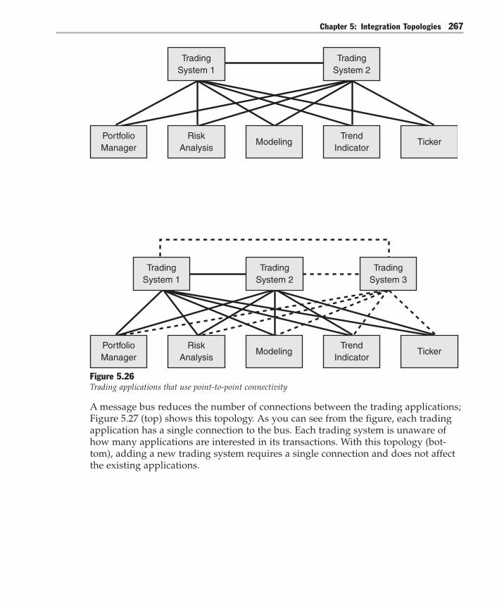
Chapter 5: Integration Topologies 267
PortfolioManager
RiskAnalysis
TradingSystem 2
TrendIndicator
TickerModeling
TradingSystem 1
TradingSystem 2
TradingSystem 1
TradingSystem 3
PortfolioManager
RiskAnalysis
TrendIndicator
TickerModeling
Figure 5.26Trading applications that use point-to-point connectivity
A message bus reduces the number of connections between the trading applications;Figure 5.27 (top) shows this topology. As you can see from the figure, each tradingapplication has a single connection to the bus. Each trading system is unaware ofhow many applications are interested in its transactions. With this topology (bot-tom), adding a new trading system requires a single connection and does not affectthe existing applications.
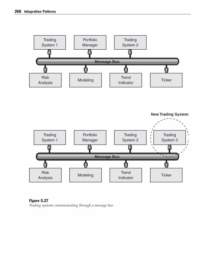
Integration Patterns268
RiskAnalysis
ModelingTrend
IndicatorTicker
TradingSystem 1
PortfolioManager
TradingSystem 2
RiskAnalysis
ModelingTrend
IndicatorTicker
TradingSystem 1
PortfolioManager
TradingSystem 2
TradingSystem 3
New Trading System
Message Bus
Message Bus
Figure 5.27Trading systems communicating through a message bus

Chapter 5: Integration Topologies 269
Resulting ContextWhen considering integration through a message bus, you should weigh the follow-ing benefits and liabilities that are associated with it:
Benefits● Improved modifiability. Each application has a single connection to the message
bus instead of multiple dedicated connections to each of the other applications.Adding or removing an application has no impact on the existing applications. Inaddition, upgrading the bus interface does not require changing any applicationsas long as the messages remain compatible with existing ones. For example, thisis the case when you add new message types.
● Reduced application complexity. The message bus transports messages betweensenders and receivers. Senders no longer interact with all the receivers that theyneed to send messages to.
● Improved performance. There are no intermediaries between the communicatingapplications. Communication latency depends only on how fast the message buscan move messages.
● Improved scalability. Adding applications has a constant low cost. In addition,you can add applications to the message bus until the message bus is saturated.A message bus is saturated when it cannot keep up with the data that it has tomove between applications.
Liabilities● Increased complexity. Integrating through a message bus increases the complex-
ity of the integration solution for the following reasons:● Architectural mismatch. The applications of an integration solution typically
make conflicting architectural assumptions [Garlan95]. Designing the messagebus interface and solving the mismatch around the data model is a difficultendeavor.
● Message bus access policies. Communication through a shared resource suchas a message bus requires you to implement policies that ensure fair accessand that resolve concurrency conflicts.
● Lowered modifiability when the bus interface breaks compatibility. Changingthe message bus interface in a way that breaks compatibility typically affects allthe applications that use the bus. In other words, the bus interface represents anextreme example of a published interface. Designing it requires foresight.

Integration Patterns270
● Lowered integrability. All the applications that are hooked to the message busmust have the same message bus interface. Applications that have incompatibleinterfaces cannot use the message bus. Because the message bus interface in-cludes a common set of command messages, message schemas, and sharedinfrastructure, these elements together define a common subset that may some-what restrict the operation of the participating applications.
● Lowered security. A message bus that uses the Broadcast-Based Publish/Subscribepattern reaches all the applications that are connected to the bus, regardless of theapplications that the message is intended for. Broadcasting to all participants maynot be acceptable if the messages contain sensitive data.
● Low tolerance for application unavailability. The receiver must be able toprocess messages when the sender passes the messages to the bus. This solutiondoes not tolerate receiver downtime. In addition, it does not provide directsupport for disconnected operation.
Security ConsiderationsBefore you use a message bus that uses Broadcast-Based Publish/Subscribe, you shouldconsider whether this configuration meets your security requirements. The applica-tions that are connected to the bus receive every message that goes through themessage bus. Participants that require a private conversation must encrypt theircommunication. Also, applications that communicate through the message bus donot have intermediate components between them. In other words, no physicalcomponent exists for mapping between different security contexts. Consequently,this configuration is appropriate when the security context is managed throughimpersonation.
Operational ConsiderationsWhen a message bus becomes saturated, message delivery may take a long time oreven fail. Saturation could occur after you add new applications or after you makechanges to the communication profile of existing applications. For example, changesto the communication profile include changes in the message size and rate. Becauseboth situations are common in bus-centered integration solutions, it is important toprevent saturation. This translates into monitoring the operation of the message busand proactively keeping the message volume below the maximum capacity of themessage bus.

Chapter 5: Integration Topologies 271
Related PatternsFor more information, see the following related patterns:● Publish/Subscribe. This pattern helps keep cooperating systems synchronized by
one-way propagation of messages; one publisher sends a message to any numberof intended subscribers.
● Message Bus Architecture [Hohpe04]. This pattern revolves around a messaginginfrastructure, and it relies on a canonical data model and a common commandset that is mentioned earlier in “Liabilities.”
● Blackboard [Buschmann96]. The Blackboard pattern describes a shared storage areathat the components of the pattern use to communicate. Consumer componentsmonitor the blackboard and grab the data that matches their interest. Producersput their output on the blackboard so that it becomes available to the others.Typically, integration applications such as rule engines and expert systems usethis pattern.
Acknowledgments[Buschmann96] Buschmann, Frank; Regine Meunier, Hans Rohnert, PeterSommerland, and Michael Stal. Pattern-Oriented Software Architecture, Volume 1: ASystem of Patterns. John Wiley & Sons Ltd, 1996.
[Chandra03] Chandra, David; Anna Liu, Ulrich Roxburgh, Andrew Mason, E. G.Nadhan, Paul Slater. Guidelines for Application Integration, Microsoft Patterns &Practices, December 2003. Available on MSDN at:http://msdn.microsoft.com/library/default.asp?url=/library/en-us/dnpag/html/eappint.asp.
[Garlan95] Garlan, David; Robert Allen, and John Ockerbloom. “ArchitecturalMismatch: Why Reuse Is So Hard,” in IEEE Software, Volume 12, Issue 6, November1995: 17-26.
[Hohpe04] Hohpe, Gregor and Bobby Woolf, Enterprise Integration Patterns: Design-ing, Building, and Deploying Messaging Solutions. Addison-Wesley, 2003.
[Levine03] Levine, Russell. “The Myth of the Disappearing Interfaces,” in BusinessIntegration Journal, November 2003.

Integration Patterns272
Publish/Subscribe
AliasesPub/Sub
ContextYou have an integration architecture consisting of several applications. A communi-cation infrastructure connects these applications in a bus, broker, or point-to-pointtopology. Some applications send multiple message types. Other applications areinterested in different combinations of these types.
For example, consider a financial system where several applications maintaincustomer information. A Customer Relationship Management (CRM) applicationholds the master customer information. However, a typical situation for integrationscenarios exists — customer information also resides in other systems that performtheir own customer information management functions. A customer-facing applica-tion generates update messages for changes to customer information, such aschanges to customer addresses. The messages must reach the CRM application aswell as the other applications that manage customer information. However, thismessage type is meaningless to the integrated applications that do not managecustomer information.
ProblemHow can an application in an integration architecture only send messages to theapplications that are interested in receiving the messages without knowing theidentities of the receivers?
ForcesIntegrating applications so that they receive only the messages they are interested ininvolves balancing the following forces:● The applications in an integration architecture consume different message types.
For example, applications that manage customer information are interested incustomer information updates. Trading applications are interested in buy and selltransactions. Applications that participate in two-phase commit transactions areinterested in commit messages.

Chapter 5: Integration Topologies 273
● An application in an integration architecture may send several message types.For example, the application may send customer information messages andoperational messages about its status. (Status is also referred to as health in thiscontext). Likewise, an application in an integration architecture is usually inter-ested only in a subset of the messages that are sent by the other applications. Forexample, a portfolio manager is interested only in the financial transactions thataffect the stocks that it manages.
● The extent to which applications let you add information to their messages varieswidely. Fixed binary messages usually provide no flexibility or limited flexibilityin this area. In contrast, it is usually easy to extend SOAP messages throughenvelope elements.
● Most integration architectures integrate proprietary applications. These applica-tions often make strong assumptions about the messages that they use to commu-nicate with other applications in the environment. Even with a flexible messageformat, it may be difficult to insert or to process message elements that theapplication does not know about.
SolutionExtend the communication infrastructure by creating topics or by dynamicallyinspecting message content. Enable listening applications to subscribe to specificmessages. Create a mechanism that sends messages to all interested subscribers. Thethree variations of the Publish/Subscribe pattern you can use to create a mechanismthat sends messages to all interested subscribers are List-Based Publish/Subscribe,Broadcast-Based Publish/Subscribe, and Content-Based Publish/Subscribe.
List-Based Publish/SubscribeA List-Based Publish/Subscribe pattern advises you to identify a subject and to main-tain a list of subscribers for that subject. When events occur, you have the subjectnotify each subscriber on the subscription list. A classic way to implement thisdesign is described in the Observer [Gamma95] pattern. When you use this pattern,you identify two classes: subjects and observers. Assuming you use a push modelupdate, you add three methods to the subject: Attach(), Detach(), and Notify().Youadd one method to the observer — Update().
To use an observer, all interested observers register with the subject by using theAttach() method. As changes occur to the subject, the subject then calls each regis-tered observer by using the Notify() method. For a detailed explanation of theObserver pattern, see Design Patterns: Elements of Reusable Object-Oriented Software[Gamma95].
Integration Patterns274
An observer works fine if you have created instances of objects that reify all yourobservers and subjects. An observer is especially well suited to situations where youhave one-to-many relationships between your subjects and your observers. How-ever, in the context of integration, you often have many observers that are linked tomany subjects, which complicates the basic Observer pattern. One way to implementthis many-to-many relationship is to create many subjects and to have each subjectcontain a list of observers.
If you use this object structure to implement Publish/Subscribe, you must write theserelationships to persistent storage between process executions. To do so within arelational database, you must add an associative table to resolve the many-to-manydependencies between subject and observer. After you write this information topersistent storage in a set of tables, you can directly query the database for the list ofsubscribers for a topic.
Maintaining lists of published topics (subjects) and subscribers (observers) and thennotifying each one individually as events occur is the essence of List-Based Publish/Subscribe implementations. A very different means of achieving the same result is aBroadcast-Based Publish/Subscribe implementation.
Broadcast-Based Publish/SubscribeWhen you use a Broadcast-Based Publish/Subscribe approach [Tannebaum01, Oki93],an event publisher creates a message and broadcasts it to the local area network(LAN). A service on each listening node inspects the subject line. If the listeningnode matches the subject line to a subject that it subscribes to, the listening nodeprocesses the message. If the subject does not match, the listening node ignores themessage.
Subject lines are hierarchical and may contain multiple fields that are separated byperiods. Listening nodes that are interested in a particular subject can subscribe tothese fields by using wildcards, if required.
Although this Broadcast-Based Publish/Subscribe implementation is an effectivemethod for decoupling producers from consumers, it is sometimes useful to identifyparticular topic subscribers. To identify topic subscribers, a coordinating processsends a message that asks listening nodes to reply if they subscribe to a particulartopic. Responses are then returned by each listening node to the provider to identifythe subscribers.
Because all messages are sent to all listening nodes, and because each node is re-sponsible for filtering unwanted messages, some authors refer to this as a publish/subscribe channel with reactive filtering [Hohpe04].

Chapter 5: Integration Topologies 275
Content-Based Publish/SubscribeBoth Broadcast-Based Publish/Subscribe implementations and List-Based Publish/Subscribe implementations can be broadly categorized as topic-based because theyboth use predefined subjects as many-to-many channels. Publish/Subscribe imple-mentations have recently evolved to include a new form — Content-Based Publish/Subscribe. The difference between topic-based and content-based approaches is asfollows:
In a topic-based system, processes exchange information through a set of pre-defined subjects (topics) which represent many-to-many distinct (and fixed) logicalchannels. Content-based systems are more flexible as subscriptions are related tospecific information content and, therefore, each combination of information itemscan actually be seen as a single dynamic logical channel. This exponential enlarge-ment of potential logical channels has changed the way to implement a pub/subsystem. [Baldoni03]
The practical implication of this approach is that messages are intelligently routedto their final destination based on the content of the message. This approach over-comes the limitation of a broadcast-based system, where distribution is coupled to amulticast tree that is based on Transmission Control Protocol (TCP). It also gives theintegration architect a great deal of flexibility when deciding on content-basedrouting logic.
Applying Publish/SubscribeFigure 5.28 shows an integration solution that consists of four applications. Thesender (also called a publisher) uses a topic-based approach to publish messages totopic A and to topic B. Three receivers (also called subscribers) subscribe to thesetopics; one receiver subscribes to topic A, one receiver subscribes to topic B, and onereceiver subscribes to both topic A and to topic B. The arrows show messages flow-ing from the publisher to each subscriber according to these subscriptions.

Integration Patterns276
Communication Infrastructure
Subscriber 1
Subscriber 2
Subscriber 3
Publisher
Topic A
Topic B
Figure 5.28Subscription to topics controls the message types that reach each subscriber
Implementing Publish/Subscribe usually affects the messages, the integrated applica-tions, and the communication infrastructure.
First, you must identify the topics or the content of interest to the receiving applica-tions. This translates into partitioning the set of message types into different subsets.For example, consider the types of messages that are sent by a trading system. Sometrading applications track buy transactions, some track sell transactions, and otherapplications track both types of transaction. Separating the message by creating abuy topic and a sell topic partitions the trading system messages into subsets aimedat these applications.
Next, you must add information to the messages that indicates the topic or thatidentifies specific content information. Sometimes you can store the topic-relatedinformation in an unused message field. Alternatively, you may be able to add anew field for the topic. For example, you may be able to insert a new element in aSOAP header. If you can neither use an existing field nor add a new one, you mustfind other ways to encode the topic into the message, or you must use a content-based approach instead.

Chapter 5: Integration Topologies 277
You must then extend the communication infrastructure so that it delivers messagesaccording to each subscriber’s subscription. The approach that you use depends onthe topology of the integration solution. For example, consider the three commontopologies. For bus integration, you can implement the subscription mechanism inthe bus interface. For broker integration, you can implement the mechanism throughsubscription lists to the broker. For point-to-point integration, you can implementthe mechanism through subscription lists in the publisher.
Finally, you must modify the integrated applications. The publisher must add thetopic-related information to each message that it publishes. For example, if the topicis encoded as a header element, the publisher must insert the topic-related informa-tion into the appropriate element. Likewise, the subscriber must specify the topics ofinterest.
Subscriptions can be either fixed or dynamic. With fixed subscriptions, the integra-tion architect sets the topics that an application subscribes to. Applications have nocontrol over their subscriptions. Usually, the subscriptions are specified when eachapplication is added to the integration solution. Figure 5.29 shows a fixed subscrip-tion to Topic A.
Subscriber 1
Publisher
Topic A
Topic C
Topic BFixed Subscription
Figure 5.29Publish/Subscribe with fixed subscription
In contrast, dynamic subscriptions enable applications to control their own subscrip-tions through a set of control messages. Applications can remove existing subscrip-tions by sending messages to the communication infrastructure that remove theapplication from the subscription list. Applications can add new subscriptions bysending messages to the communication infrastructure that add the application to asubscription list. Most communication infrastructures that have Publish/Subscribecapabilities provide this feature. However, supporting dynamic subscriptions is nota requirement.

Integration Patterns278
Subscriber 1
Publisher
Topic A
Topic C
Topic B
Subscriber 1
Publisher
Topic A
Initial Subscription
Final Subscription
Topic B
Topic C
Figure 5.30Publish/Subscribe with dynamic subscriptions
Figure 5.30 shows how dynamic subscriptions function. The top part of Figure 5.30shows the initial subscription to topic A. The application then sends a message thatremoves it from the subscription list for topic A. The application then sends twomessages that subscribe the application to topic B and topic C. The bottom part ofFigure 5.30 shows the final subscription after these control messages are sent.

Chapter 5: Integration Topologies 279
Related Decisions
After you decide to use Publish/Subscribe, you must make the following decisions:● Initial subscription. You must decide how subscribers communicate their sub-
scriptions to the communication infrastructure when they are first added to thesolution.
● Wildcard subscriptions. You must decide if your publish/subscribe mechanismneeds to support wildcard subscriptions. Wildcard subscriptions enable subscrib-ers to subscribe to multiple topics through one subscription.
● Static or dynamic subscriptions. You must decide if the applications in yourintegration solution need to change their subscriptions dynamically.
● Topic discovery. You must decide how subscribers discover the available topics ifthe solution supports dynamic subscriptions.
Responsibilities and Collaborations
Table 5.4 summarizes the responsibilities and collaborations of the parties involvedin Publish/Subscribe.
Table 5.4: Responsibilities and Collaborations Among Publish/Subscribe Components
Components Responsibilities Collaborations
Communication – Maintains the subscribers’ – The publisher publishes messages.infrastructure subscriptions. – The subscriber subscribes to
– Inspects the topic-related topics and receives messages.information or the content informationthat is included in each publishedmessage.– Transports the message to thesubscribed applications.
Publisher – Inserts topic-related information or – The communication infrastructurecontent information in each message. transports messages to subscribers.– Publishes the message to thecommunication infrastructure.
Subscriber – Subscribes to one or more topics – The communication infrastructureor message content types. transports published messages– Consumes messages published from the publisher.to the subscribed topics.

Integration Patterns280
ExampleMicrosoft BizTalk Server 2004 uses the Publish/Subscribe pattern internally to receive,to route, and to send messages. BizTalk Server receives messages through inputports and stores them in the MessageBox database. Orchestration ports and sendports consume messages from this database based on their subscriptions. Figure 5.31illustrates this arrangement.
Orchestration Port 1
Orchestration Port 2
Subscribe
Publish
Send Port 1
Send Port 2
Send Port 3
Receive Port
MessageBoxDatabase
Figure 5.31Publish/Subscribe in BizTalk Server 2004
Resulting ContextUsing Publish/Subscribe has the following benefits and liabilities. Evaluate thisinformation to help you decide whether you should implement Publish/Subscribe:
Benefits● Lowered coupling. The publisher is not aware of the number of subscribers, of
the identities of the subscribers, or of the message types that the subscribers aresubscribed to.
● Improved security. The communication infrastructure transports the publishedmessages only to the applications that are subscribed to the corresponding topic.Specific applications can exchange messages directly, excluding other applica-tions from the message exchange.
● Improved testability. Topics usually reduce the number of messages that arerequired for testing.

Chapter 5: Integration Topologies 281
Liabilities● Increased complexity. Publish/Subscribe requires you to address the following:
● You have to design a message classification scheme for topic implementation.● You have to implement the subscription mechanism.● You have to modify the publisher and the subscribers.
● Increased maintenance effort. Managing topics requires maintenance work.Organizations that maintain many topics usually have formal procedures fortheir use.
● Decreased performance. Subscription management adds overhead. This over-head increases the latency of message exchange, and this latency decreasesperformance.
Testing ConsiderationsThe topics of a Publish/Subscribe implementation facilitate the testing of an integra-tion solution. Subscriptions provide isolation by segmenting the message space. Bysubscribing only to the topics or to the content of interest, testers and testing toolshave fewer messages to sift through. Likewise, by subscribing to other topics orcontent, testers can catch messages that are published to the wrong topic.
Security ConsiderationsAn integration solution that uses Publish/Subscribe can restrict the participants of amessage exchange, thus enabling applications to have private message exchanges.Depending on the topology, the messages may still be physically transported to allthe applications in the integration architecture. For example, all the messages aretransported to all the applications if your integration solution uses the Message Bususing Broadcast-Based Publish/Subscribe pattern. However, the interface between thecommunication infrastructure and the application enforces filtering according toeach application’s subscriptions.
Operational ConsiderationsMany integration solutions that use Publish/Subscribe have topics or content that isdedicated to messages about the applications’ health. This separation facilitates yourability to monitor various operational parameters and to control the applications inthe integration solution.

Integration Patterns282
Related PatternsFor more information about Publish/Subscribe, see other similar patterns:● Message Bus and Message Broker describe two common integration topologies.● Observer [Gamma95] provides a mechanism for decoupling dependencies be-
tween applications.● Publisher-Subscriber [Buschmann96] facilitates state synchronization between
cooperating components.● Publish-Subscribe Channel [Hohpe04] provides a way to broadcast events to all the
receivers (subscribers) that subscribe to a specific topic.
Acknowledgments[Baldoni03] Baldoni, R.; M. Contenti, and A. Virgillito. “The Evolution of Publish/Subscribe Communication Systems.” Future Directions of Distributed Computing.Springer Verlag LNCS Vol. 2584, 2003.
[Buschmann96] Buschmann, Frank; Regine Meunier, Hans Rohnert, PeterSommerlad, and Michael Stal. Pattern-Oriented Software Architecture, Volume 1: ASystem of Patterns. John Wiley & Sons Ltd, 1996.
[Gamma95] Gamma, Erich; Richard Helm, Ralph Johnson, and John Vlissides.Design Patterns: Elements of Reusable Object-Oriented Software. Addison-Wesley, 1995.
[Hohpe04] Hohpe, Gregor, and Bobby Woolf. Enterprise Integration Patterns: Design-ing, Building and Deploying Messaging Solutions. Addison-Wesley, 2004.
[Oki93] Oki, B.; M. Pfluegel, A. Siegel, and D. Skeen. “The Information Bus - AnArchitecture for Extensive Distributed Systems.” Proceedings of the 1993 ACMSymposium on Operating Systems Principles, December 1993.
[Tannebaum01] Tannebaum, Andrew. Modern Operating Systems. 2nd ed. Prentice-Hall, 2001.

6Additional Integration Patterns
This chapter completes this investigation of integration patterns by exploring thePipes and Filters pattern and the Gateway pattern. Both patterns are simple butvaluable for resolving integration problems.
Even though this chapter completes this discussion, you can obtain informationabout additional integration patterns in the Appendix.
Pipes and FiltersPipes and Filters provides a solution for moving the output of one system into an-other system. The pipe is the portion of the code that is connected to the sourcesystem and to the sink or the receiving system. The filter is the portion of the codethat transforms the data so that the sink program can process it.
This pattern is useful when you need to transform the data from one system into adifferent format to integrate that data into another system. A simple example is theconversion of data from ASCII to Extended Binary Coded Decimal Interchange Code(EBCDIC) that occurs when data moves from a desktop computer to a mainframe.
Figure 6.1 shows a source system integrated with a sink system. The sourcesystem uses multiple filters to transform the data to the format that the sinksystem requires.

Integration Patterns284
Source
Pipe
Filter 1
Pipe
Filter 2
Pipe
Sink
Figure 6.1A source system integrated with the sink system through Pipes and Filters
In the Global Bank scenario, the Pipes and Filters pattern is used to handle the com-munication between Microsoft BizTalk Server 2004 and external payment channels.
GatewayThe Gateway pattern abstracts the access to an external system to a single interface.The pattern eliminates the need for multiple systems to understand how to connectto the external system. Therefore, the Gateway pattern simplifies the developmentand maintenance processes that are related to accessing external systems.

Chapter 6: Additional Integration Patterns 285
Common uses for the Gateway pattern include accessing mainframe programs andprocessing credit card transactions. For each of these common uses, the gatewayreplaces direct access to the external resource or system, as shown in Figure 6.2.
Application 2 Gateway ExternalResource
Application 1
Application 3
Figure 6.2Gateway replaces direct access to the external resource
In the Global Bank scenario, the Gateway pattern is implemented by using MicrosoftHost Integration Server 2004. Host Integration Server 2004 provides the solution forintegrating the mainframe to the enterprise.
Integration Layers PatternsThe following table summarizes the two patterns just discussed and shows thecorresponding implementation patterns.
Table 6.1: Integration Layers Patterns
Pattern Problem Associated implementations
Gateway How can you make the applications of an Implementing Gateway withintegration solution access an external Host Integration Server 2004system without introducing many-to-onecoupling between the applications and theexternal system?
Pipes and Filters How do you implement a sequence of Implementing Pipes and Filterstransformations so that you can combine with BizTalk Server 2004and reuse them independently?
Integration Patterns286
Pipes and Filters
AliasesData Flow Architecture
ContextYou have an integration solution that consists of several financial applications. Theapplications use a wide range of formats — such as the Interactive Financial Ex-change (IFX) format, the Open Financial Exchange (OFX) format, and the ElectronicData Interchange (EDI) format — for the messages that correspond to payment,withdrawal, deposit, and funds transfer transactions.
Integrating these applications requires processing the messages in different ways.For example, converting an XML-like message into another XML-like messageinvolves an XSLT transformation. Converting an EDI data message into an XML-likemessage involves a transformation engine and transformation rules. Verifyingthe identity of the sender involves verifying the digital signature attached to themessage. In effect, the integration solution applies several transformations tothe messages that are exchanged by its participants.
ProblemHow do you implement a sequence of transformations so that you can combine andreuse them independently?
ForcesImplementing transformations that can be combined and reused in different applica-tions involves balancing the following forces:● Many applications process large volumes of similar data elements. For example,
trading systems handle stock quotes, telecommunication billing systems handlecall data records, and laboratory information management systems (LIMS)handle test results.
● The processing of data elements can be broken down into a sequence of indi-vidual transformations. For example, processing XML messages typically in-volves a series of XSLT transformations.
● The functional decomposition of a transformation f(x) into g(x) and h(z) (wheref[x]=g[x]?h[z]) does not change the transformation. However, when separatecomponents implement g and h, the communication between them (that is,passing the output of g[x] to h[z]) incurs overhead. This overhead increases thelatency of a g(x)?h(z) implementation compared to an f(x) implementation.

Chapter 6: Additional Integration Patterns 287
SolutionImplement the transformations by using a sequence of filter components, whereeach filter component receives an input message, applies a simple transformation,and sends the transformed message to the next component. Conduct the messagesthrough pipes [McIlroy64] that connect filter outputs and inputs and that buffer thecommunication between the filters.
The left side of Figure 6.3 shows a configuration that has two filters. A source appli-cation feeds messages through the pipe into filter 1. The filter transforms eachmessage it receives and then sends each transformed message as output into thenext pipe. The pipe carries the transformed message to filter 2. The pipe also buffersany messages that filter 1 sends and that filter 2 is not ready to process. The secondfilter then applies its transformation and passes the message through the pipe to thesink application. The sink application then consumes the message. This configura-tion requires the following:● The output of the source must be compatible with the input of filter 1.● The output of filter 1 must be compatible with the input of filter 2.● The output of filter 2 must be compatible with the input of the sink.
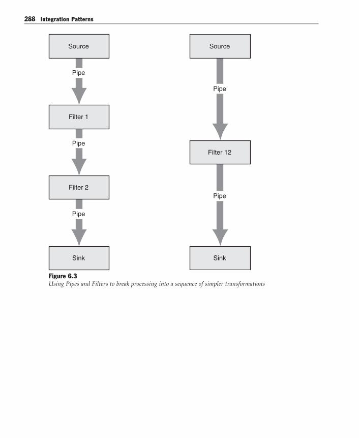
Integration Patterns288
Pipe
Source
Pipe
Filter 1
Pipe
Filter 2
Pipe
Sink
Source
Pipe
Filter 12
Sink
Figure 6.3Using Pipes and Filters to break processing into a sequence of simpler transformations

Chapter 6: Additional Integration Patterns 289
The right side of Figure 6.3 shows a single filter. From a functional perspective, eachconfiguration implements a transfer function. The data flows only one way and thefilters communicate solely by exchanging messages. They do not share state; there-fore, the transfer functions have no side effects. Consequently, the series configura-tion of filter 1 and filter 2 is functionally equivalent to a single filter that implementsthe composition of the two transfer functions (filter 12 in the figure).
Comparing the two configurations illustrates their tradeoffs:● The two-filter configuration breaks the transformation between the source and
the sink into two simpler transformations. Lowering the complexity of the indi-vidual filters makes them easier to implement and improves their testability. Italso increases their potential for reuse because each filter is built with a smallerset of assumptions about the environment that it operates in.
● The single-filter configuration implements the transformation by using onespecialized component. The one hop that exists between input and output andthe elimination of the interfilter communication translate into low latency andoverhead.
In summary, the key tradeoffs in choosing between a combination of generic filtersand a single specialized filter are reusability and performance.
In the context of pipes and filters, a transformation refers to any transfer functionthat a filter might implement. For example, transformations that are commonly usedin integration solutions include the following:● Conversion, such as converting Extended Binary Coded Decimal Interchange
Code (EBCDIC) to ASCII● Enrichment, such as adding information to incoming messages● Filtering, such as discarding messages that match a specific criteria● Batching, such as aggregating 10 incoming messages and sending them together
in a single outgoing message● Consolidation, such as combining the data elements of three related messages
into a single outgoing message
In practice, the transfer function corresponds to a transformation that is specificenough to be useful, yet simple enough to be reused in a different context. Identify-ing the transformations for a problem domain is a difficult design problem.

Integration Patterns290
Table 6.2 shows the responsibilities and collaborations that are associated with pipesand filters.
Table 6.2: Responsibilities and Collaborations of Pipes and Filters
Responsibilities Collaborations
– A filter takes a message from its input, – A filter produces and consumes messages.applies a transformation, and sends thetransformed message as output.
– A pipe transports messages between filters. – A pipe connects the filter with the producer(Sources and sinks are special filters without and the consumer. A pipe transports andinputs or outputs.) buffers messages.
ExampleConsider a Web service for printing insurance policies. The service accepts XMLmessages from agency management systems. Incoming messages are based on theACORD XML specification, an insurance industry standard. However, each agencyhas added proprietary extensions to the standard ACORD transactions. A printrequest message specifies the type of document to be generated, for example, anHTML document or a Portable Document Format (PDF) document. The request alsoincludes policy data such as client information, coverage, and endorsements. TheWeb service processes the proprietary extensions and adds the jurisdiction-specificinformation that should appear on the printed documents, such as local or regionalrequirements and restrictions. The Web service then generates the documents in therequested format and returns them to the agency management system.
You could implement these processing steps as a single transformation within theWeb service. Although viable, this solution does not let you reuse the transformationin a different context. In addition, to accommodate new requirements, you wouldhave to change several components of the Web service. For example, you wouldhave to change several components if a new requirement calls for decrypting someelements of the incoming messages.
An implementation that is based on Pipes and Filters provides an elegant alternativefor the printing Web service. Figure 6.4 illustrates a solution that involves threeseparate transformations. The transformations are implemented as filters thathandle conversion, enrichment, and rendering.
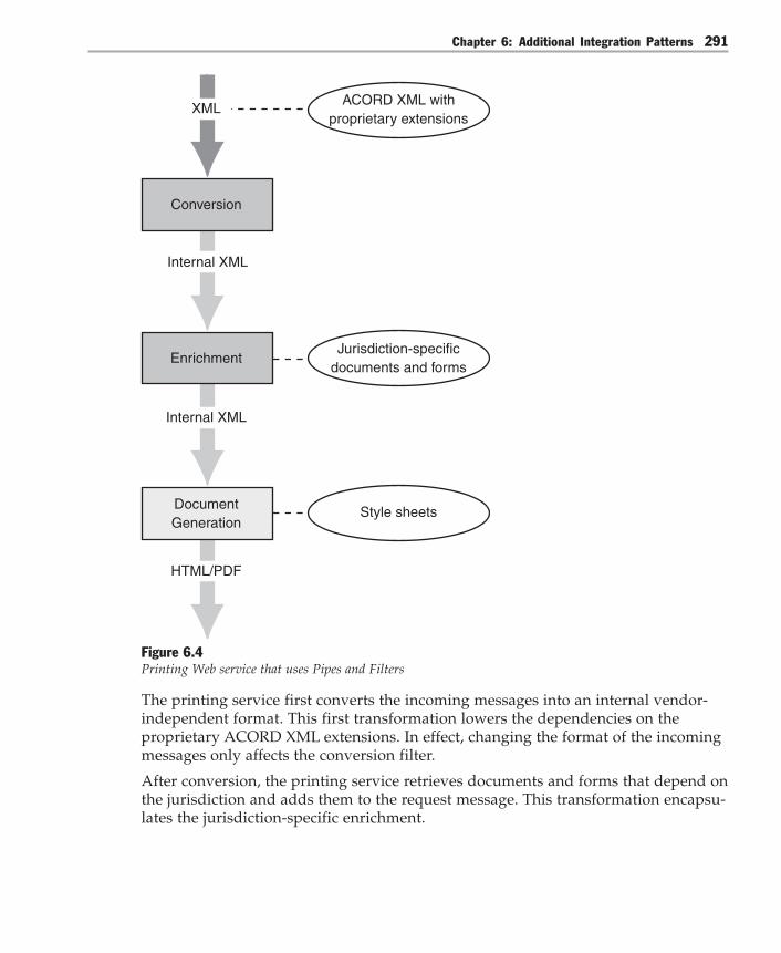
Chapter 6: Additional Integration Patterns 291
Internal XML
DocumentGeneration
HTML/PDF
XML
Conversion
Internal XML
Enrichment
Style sheets
Jurisdiction-specificdocuments and forms
ACORD XML withproprietary extensions
Figure 6.4Printing Web service that uses Pipes and Filters
The printing service first converts the incoming messages into an internal vendor-independent format. This first transformation lowers the dependencies on theproprietary ACORD XML extensions. In effect, changing the format of the incomingmessages only affects the conversion filter.
After conversion, the printing service retrieves documents and forms that depend onthe jurisdiction and adds them to the request message. This transformation encapsu-lates the jurisdiction-specific enrichment.

Integration Patterns292
When the message contains all the information that comprises the final electronicdocument, a document generation filter converts the message to HTML or PDFformat. A style sheet repository provides information about the appearance of eachdocument. This last transformation encapsulates the knowledge of rendering legallybinding documents.
In this example, the Pipes and Filters implementation of the printing Web service hasthe following benefits that make it preferable to implementing the Web service as asingle monolithic transformation:● Separation of concerns. Each filter solves a different problem.● Division of labor. ACORD XML experts implement the conversion of the
proprietary extensions into an internal vendor-independent format. Peoplewho specialize in dealing with the intricacies of each jurisdiction assist with theimplementation of the filter that handles those aspects. Formatters and layoutexperts implement document generation.
● Specialization. Document-rendering is CPU intensive and, in the case of a PDFdocument, uses floating point operations. You can deploy the rendering tohardware that meets these requirements.
● Reuse. Each filter encapsulates fewer context-specific assumptions. For example,the document generator takes messages that conform to some schema and gener-ates an HTML or PDF document. Other applications can reuse this filter.
Resulting ContextUsing Pipes and Filters results in the following benefits and liabilities:
Benefits● Improved reusability. Filters that implement simple transformations typically
encapsulate fewer assumptions about the problem they are solving than filtersthat implement complex transformations. For example, converting a messagefrom one XML encapsulation to another encapsulates fewer assumptions aboutthat conversion than generating a PDF document from an XML message. Thesimpler filters can be reused in other solutions that require similar transforma-tions.
● Improved performance. A Pipes and Filters solution processes messages as soonas they are received. Typically, filters do not wait for a scheduling component tostart processing.
● Reduced coupling. Filters communicate solely through message exchange. Theydo not share state and are therefore unaware of other filters and sinks that con-sume their outputs. In addition, filters are unaware of the application that theyare working in.

Chapter 6: Additional Integration Patterns 293
● Improved modifiability. A Pipes and Filters solution can change the filter configu-ration dynamically. Organizations that use integration solutions that are subjectto service level agreements usually monitor the quality of the services theyprovide on a constant basis. These organizations usually react proactively to offerthe agreed-upon levels of service. For example, a Pipes and Filters solution makesit easier for an organization to maintain a service level agreement because a filtercan be replaced by another filter that has different resource requirements.
Liabilities● Increased complexity. Designing filters typically requires expert domain knowl-
edge. It also requires several good examples to generalize from. The challenge ofidentifying reusable transformations makes filter development an even moredifficult endeavor.
● Lowered performance due to communication overhead. Transferring messagesbetween filters incurs communication overhead. This overhead does not contrib-ute directly to the outcome of the transformation; it merely increases the latency.
● Increased complexity due to error handling. Filters have no knowledge of thecontext that they operate in. For example, a filter that enriches XML messagescould run in a financial application, in a telecommunications application, or in anavionics application. Error handling in a Pipes and Filters configuration usually iscumbersome.
● Increased maintainability effort. A Pipes and Filters configuration usually hasmore components than a monolithic implementation (see Figure 6.4). Eachcomponent adds maintenance effort, system management effort, and opportuni-ties for failure.
● Increased complexity of assessing the state. The Pipes and Filters pattern distrib-utes the state of the computation across several components. The distributionmakes querying the state a complex operation.
Testing ConsiderationsBreaking processing into a sequence of transformations facilitates testing becauseyou can test each component individually.
Known UsesThe input and output pipelines of Microsoft BizTalk Server 2004 revolve aroundPipes and Filters. The pipelines process messages as they enter and leave the engine.Each pipeline consists of a sequence of transformations that users can customize. Forexample, the receive pipeline provides filters that perform the following actions:● The filters decode MIME and S/MIME messages.
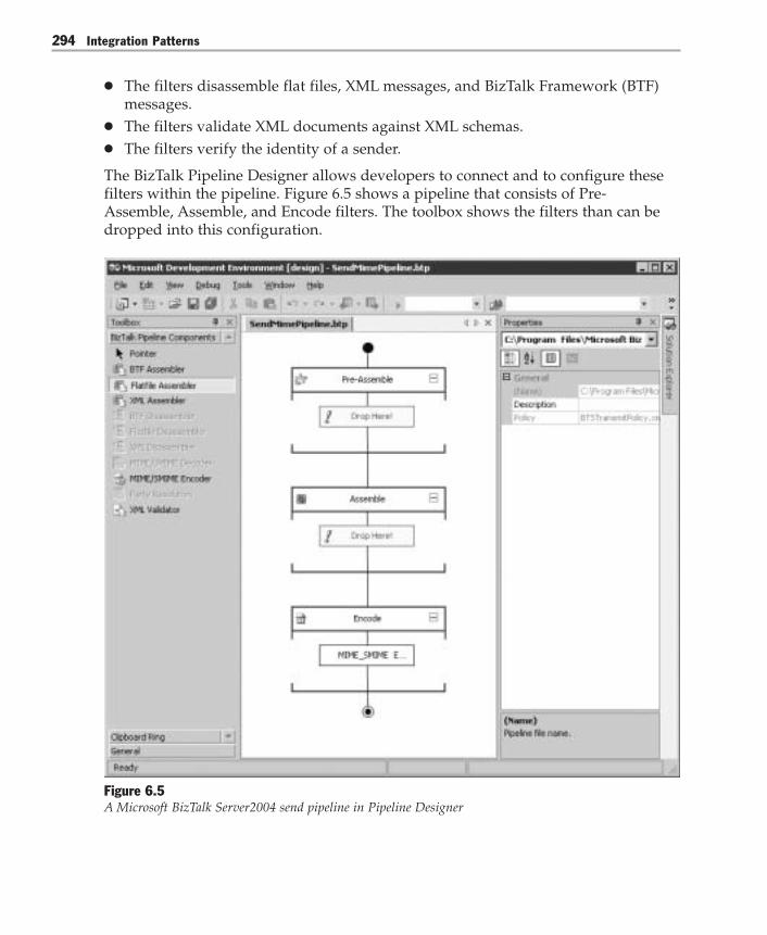
Integration Patterns294
● The filters disassemble flat files, XML messages, and BizTalk Framework (BTF)messages.
● The filters validate XML documents against XML schemas.● The filters verify the identity of a sender.
The BizTalk Pipeline Designer allows developers to connect and to configure thesefilters within the pipeline. Figure 6.5 shows a pipeline that consists of Pre-Assemble, Assemble, and Encode filters. The toolbox shows the filters than can bedropped into this configuration.
Figure 6.5A Microsoft BizTalk Server2004 send pipeline in Pipeline Designer

Chapter 6: Additional Integration Patterns 295
Many other integration products use Pipes and Filters for message transformation. Inparticular, XML-based products rely on XSL processors to convert XML documentsfrom one schema to another. In effect, the XSL processors act as programmable filtersthat transform XML.
Related PatternsFor more information about Pipes and Filters, see the following related patterns:● Implementing Pipes and Filters with BizTalk Server 2004. This pattern uses the Global
Bank scenario to show how you can use BizTalk Server 2004 to implement Pipesand Filters.
● Pipes and Filters [Shaw96, Buschmann96, Hohpe03].● Intercepting Filter [Trowbridge03]. This version of Intercepting Filter discusses the
pattern in the context of Web applications built using the Microsoft .NET Frame-work. Developers can chain filters to implement preprocessing and post-process-ing tasks such as extracting header information and rewriting URLs.
● In-band and Out-of-band Partitions [Manolescu97]. This pattern remedies the lackof a component that has a global context in Pipes and Filters systems. The out-of-band partition is context-aware; therefore, it can configure the filters and handleerrors.
Acknowledgments[Buschmann96] Buschmann, Frank; Regine Meunier, Hans Rohnert, PeterSommerland, and Michael Stal. Pattern-Oriented Software Architecture. John Wiley &Sons Ltd, 1996.
[Hohpe04] Hohpe, Gregor and Bobby Woolf, Enterprise Integration Patterns: Design-ing, Building, and Deploying Messaging Solutions. Addison-Wesley, 2004.
[Manolescu97] Manolescu, Dragos. “A Data Flow Pattern Language,” in Proceedingsof the 4th Pattern Languages of Programming, September 1997, Monticello, Illinois.
[McIlroy64] The fluid-flow analogy dates from the days of the first UNIX systemsand is attributed to Douglas McIlroy; seehttp://cm.bell-labs.com/cm/cs/who/dmr/mdmpipe.html.
[Trowbridge03] Trowbridge, David; Dave Mancini, Dave Quick, Gregor Hohpe,James Newkirk, and David Lavigne. Enterprise Solution Patterns Using Microsoft.NET. Microsoft Press, 2003. Also available on the MSDN Architecture Center at:http://msdn.microsoft.com/architecture/patterns/default.aspx?pull=/library/en-us/dnpatterns/html/Esp.asp.
[Shaw96] Shaw, Mary, and David Garlan, Software Architecture: Perspectives on anEmerging Discipline. Prentice Hall, 1996.

Integration Patterns296
Implementing Pipes and Filters with BizTalk Server 2004
ContextYou are implementing Pipes and Filters by using Microsoft BizTalk Server 2004.
BackgroundThe Global Bank scenario includes the Execute Scheduled Payment use case. Thisuse case permits Global Bank to transfer funds from a customer’s account to aspecified target account. The target account can reside in one of three systems:● An internal banking system that uses an internal Global Bank payment channel.● An external banking system that uses encrypted and signed e-mail messages to
transfer funds. One such system is the Society for Worldwide Interbank FinancialTelecommunication (SWIFT) payment channel.
● An external banking system that cannot accept an electronic funds transfer andtherefore has to receive a paper check. This is an external manual paymentchannel.
This pattern describes how to implement the Execute Scheduled Payment use case inthe Global Bank scenario by using the Pipes and Filters pattern that is describedearlier in this guide. This implementation uses BizTalk Server 2004 to transform andto route funds to the target accounts by using the correct channel, as shown inFigure 6.6.
Internal BankPayment Channel
External BankPayment Channel
External ManualPayment Channel
SWIFT
Manual BusinessProcess Traditional Mail
Encrypted andSigned E-mail
Pipes and Filters:BizTalk Server 2004
GlobalBank
Figure 6.6BizTalk Server2004 as Pipes and Filters
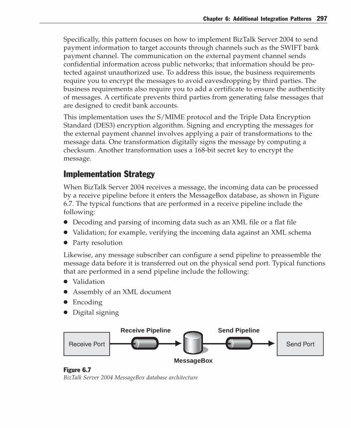
Chapter 6: Additional Integration Patterns 297
Specifically, this pattern focuses on how to implement BizTalk Server 2004 to sendpayment information to target accounts through channels such as the SWIFT bankpayment channel. The communication on the external payment channel sendsconfidential information across public networks; that information should be pro-tected against unauthorized use. To address this issue, the business requirementsrequire you to encrypt the messages to avoid eavesdropping by third parties. Thebusiness requirements also require you to add a certificate to ensure the authenticityof messages. A certificate prevents third parties from generating false messages thatare designed to credit bank accounts.
This implementation uses the S/MIME protocol and the Triple Data EncryptionStandard (DES3) encryption algorithm. Signing and encrypting the messages forthe external payment channel involves applying a pair of transformations to themessage data. One transformation digitally signs the message by computing achecksum. Another transformation uses a 168-bit secret key to encrypt themessage.
Implementation StrategyWhen BizTalk Server 2004 receives a message, the incoming data can be processedby a receive pipeline before it enters the MessageBox database, as shown in Figure6.7. The typical functions that are performed in a receive pipeline include thefollowing:● Decoding and parsing of incoming data such as an XML file or a flat file● Validation; for example, verifying the incoming data against an XML schema● Party resolution
Likewise, any message subscriber can configure a send pipeline to preassemble themessage data before it is transferred out on the physical send port. Typical functionsthat are performed in a send pipeline include the following:● Validation● Assembly of an XML document● Encoding● Digital signing
Receive Pipeline
Receive Port
Send Pipeline
Send Port
MessageBoxFigure 6.7BizTalk Server 2004 MessageBox database architecture
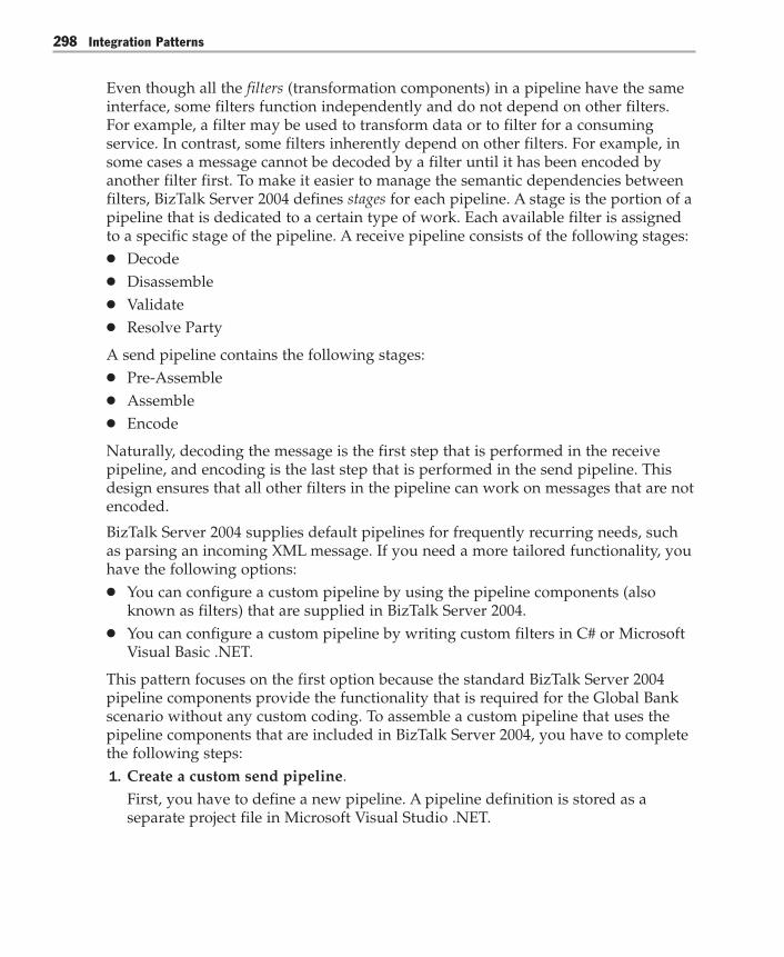
Integration Patterns298
Even though all the filters (transformation components) in a pipeline have the sameinterface, some filters function independently and do not depend on other filters.For example, a filter may be used to transform data or to filter for a consumingservice. In contrast, some filters inherently depend on other filters. For example, insome cases a message cannot be decoded by a filter until it has been encoded byanother filter first. To make it easier to manage the semantic dependencies betweenfilters, BizTalk Server 2004 defines stages for each pipeline. A stage is the portion of apipeline that is dedicated to a certain type of work. Each available filter is assignedto a specific stage of the pipeline. A receive pipeline consists of the following stages:● Decode● Disassemble● Validate● Resolve Party
A send pipeline contains the following stages:● Pre-Assemble● Assemble● Encode
Naturally, decoding the message is the first step that is performed in the receivepipeline, and encoding is the last step that is performed in the send pipeline. Thisdesign ensures that all other filters in the pipeline can work on messages that are notencoded.
BizTalk Server 2004 supplies default pipelines for frequently recurring needs, suchas parsing an incoming XML message. If you need a more tailored functionality, youhave the following options:● You can configure a custom pipeline by using the pipeline components (also
known as filters) that are supplied in BizTalk Server 2004.● You can configure a custom pipeline by writing custom filters in C# or Microsoft
Visual Basic .NET.
This pattern focuses on the first option because the standard BizTalk Server 2004pipeline components provide the functionality that is required for the Global Bankscenario without any custom coding. To assemble a custom pipeline that uses thepipeline components that are included in BizTalk Server 2004, you have to completethe following steps:1. Create a custom send pipeline.
First, you have to define a new pipeline. A pipeline definition is stored as aseparate project file in Microsoft Visual Studio .NET.

Chapter 6: Additional Integration Patterns 299
2. Assign and configure the filters.The Pipeline Designer in BizTalk Server 2004 enables you to drag filters into thenew pipeline. You can configure each filter by using the properties editor.
3. Build and deploy the pipeline.Pipeline definitions are compiled into a .NET Framework assembly. Before youcan configure a send port or a receive port by using the custom pipelinedefinition, you have to deploy the assembly.
4. Assign a certificate to BizTalk Server 2004.This step is needed because the business requirement includes signing theoutbound message with a certificate. Such a certificate is usually obtained froman outside certificate authority and is loaded into the certificate store of the localoperating system. After the certificate is loaded, the certificate thumbprint has tobe entered into the BizTalk Administration console. The thumbprint is a uniqueidentifier.For a detailed description of certificates, see “Certificate Stores” in Windows XPProfessional Product Documentation [Microsoft04].
5. Configure the send port to use the custom pipeline.After the custom pipeline is deployed, you can reference the custom pipeline inthe configuration settings of a send port.
ExampleTo make the communication on Global Bank’s external payment channel secure, youmust create a custom send pipeline that signs and encrypts the outbound messages.This pipeline is used in conjunction with the Message Broker described in Implement-ing Message Broker with BizTalk Server 2004.
Based on the implementation strategy, you have to complete the following steps toimplement the new custom pipeline by using BizTalk Server 2004.
Step 1: Create a Custom Send PipelinePipeline definitions are created in Visual Studio .NET and are compiled into a.NETFramework assembly by using the Pipeline Designer. First, create a new BizTalkServer 2004 solution in Visual Studio .NET. Next, select Send Pipeline in the itemlist, and then add it to the solution. This opens the Pipeline Designer.
Step 2: Assign and Configure the FiltersIn this step, you use the Pipeline Designer to drag predefined filter componentsfrom the Toolbox into the pipeline, as shown in Figure 6.8.
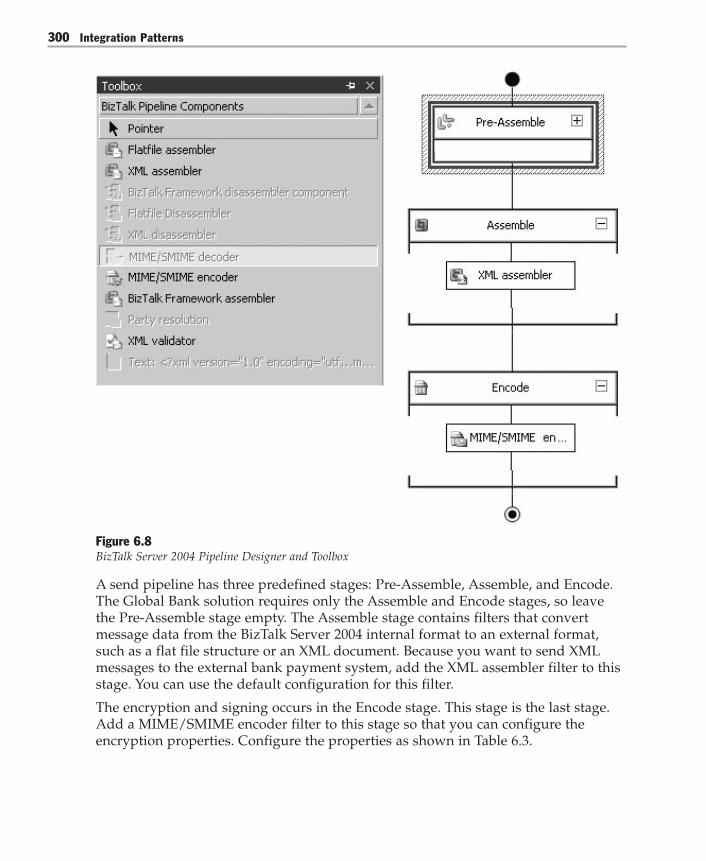
Integration Patterns300
Figure 6.8BizTalk Server 2004 Pipeline Designer and Toolbox
A send pipeline has three predefined stages: Pre-Assemble, Assemble, and Encode.The Global Bank solution requires only the Assemble and Encode stages, so leavethe Pre-Assemble stage empty. The Assemble stage contains filters that convertmessage data from the BizTalk Server 2004 internal format to an external format,such as a flat file structure or an XML document. Because you want to send XMLmessages to the external bank payment system, add the XML assembler filter to thisstage. You can use the default configuration for this filter.
The encryption and signing occurs in the Encode stage. This stage is the last stage.Add a MIME/SMIME encoder filter to this stage so that you can configure theencryption properties. Configure the properties as shown in Table 6.3.
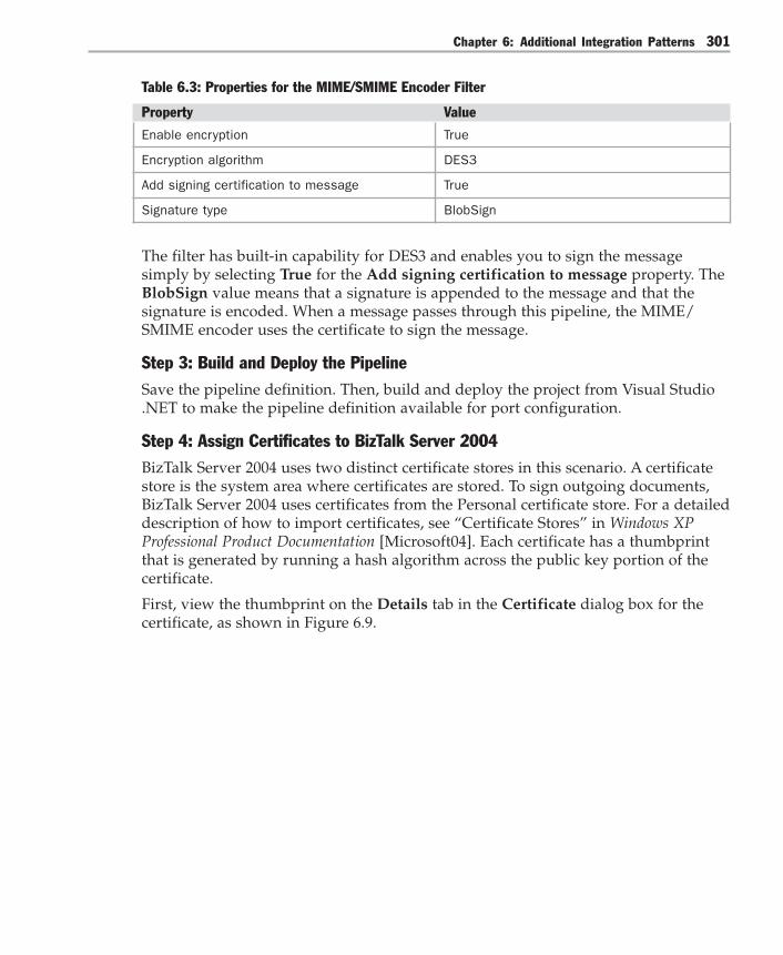
Chapter 6: Additional Integration Patterns 301
Table 6.3: Properties for the MIME/SMIME Encoder Filter
Property Value
Enable encryption True
Encryption algorithm DES3
Add signing certification to message True
Signature type BlobSign
The filter has built-in capability for DES3 and enables you to sign the messagesimply by selecting True for the Add signing certification to message property. TheBlobSign value means that a signature is appended to the message and that thesignature is encoded. When a message passes through this pipeline, the MIME/SMIME encoder uses the certificate to sign the message.
Step 3: Build and Deploy the PipelineSave the pipeline definition. Then, build and deploy the project from Visual Studio.NET to make the pipeline definition available for port configuration.
Step 4: Assign Certificates to BizTalk Server 2004BizTalk Server 2004 uses two distinct certificate stores in this scenario. A certificatestore is the system area where certificates are stored. To sign outgoing documents,BizTalk Server 2004 uses certificates from the Personal certificate store. For a detaileddescription of how to import certificates, see “Certificate Stores” in Windows XPProfessional Product Documentation [Microsoft04]. Each certificate has a thumbprintthat is generated by running a hash algorithm across the public key portion of thecertificate.
First, view the thumbprint on the Details tab in the Certificate dialog box for thecertificate, as shown in Figure 6.9.

Integration Patterns302
Figure 6.9A certificate thumbprint
Next, configure the server running BizTalk Server 2004 with the certificate thumb-print. To do so, start the BizTalk Administration console. Then, configure the signingcertificate thumbprint on the General tab in the Microsoft BizTalk Server 2004(Local) Properties dialog box, as shown in Figure 6.10.

Chapter 6: Additional Integration Patterns 303
Figure 6.10BizTalk Server 2004 properties
Use the same certificate to sign outgoing messages for all servers in the BizTalkServer 2004 group.
To encrypt outgoing messages, BizTalk Server 2004 uses the Local Machine\OtherPeople certificate store. This certificate store holds public key certificates. Multiplecertificates can be stored and then used to encrypt messages to specific parties. Thecertificate used to encrypt the message is specified in the send port configuration.

Integration Patterns304
Step 5: Configure the Send Port to Use the Custom PipelineNow that the custom pipeline definition is deployed in a global assembly, you canuse it in the configuration of the send port, as shown in Figure 6.11.
Figure 6.11BizTalk Server 2004 send port properties
You can now connect the new send port to the MessageBox database as described inImplementing Message Broker with BizTalk Server 2004.

Chapter 6: Additional Integration Patterns 305
Resulting ContextUsing Pipes and Filters with BizTalk Server 2004 results in the following benefits andliabilities:
Benefits● Filter reuse. BizTalk Server 2004 users can reuse both the pipeline definitions and
the set of pipeline filters across different ports. For example, the MIME/SMIMEencoder filter is suitable for any application that needs to send MIME or S/MIMEmessages.
● Amenable for graphical tools. Programming the pipeline involves connectingand configuring filters by dragging components rather than by writing sourcecode.
● Developer specialization. Pipes and Filters fosters the division of labor betweendifferent types of users. For example, C# developers build filters by using theMicrosoft Small Business Customer Manager Filter SDK. Business users anddevelopers who use BizTalk Server 2004 can assemble them without any pro-gramming.
Liabilities● Restricts the filter types. BizTalk Server 2004 pipelines use filters that have a
single input and a single output. This implementation of Pipes and Filters cannotaccommodate filters that do not fit within this constraint.
● Overhead cost. BizTalk Server 2004 pipelines are very powerful when there arebusiness rules and other types of processes on the data. However, the businessrules and processes on the data are overhead if all that is required is a simple pipebetween applications.
Testing ConsiderationsThere are two main test scenarios when you use BizTalk Server 2004 to implementPipes and Filters. The test scenario that applies to you depends on the customizationoption that you choose as your implementation strategy:● Configure a custom pipeline by using the filters that are supplied with BizTalk
Server 2004. In this case, you build the custom pipeline and configure the filtersby using the Pipeline Designer. You then create a test configuration that uses thiscustom pipeline in either a receive port or a send port. You can then submit testmessages and validate the resulting output.

Integration Patterns306
● Configure a custom pipeline by writing custom filters in C# or Visual Basic.NET. In this case, you can test the pipeline component by creating a testconfiguration that uses the component in a custom pipeline as described earlier.You can also use Microsoft Visual Studio .NET to review the pipeline componentcode.
Security ConsiderationsIn addition to security features that are provided by the transports, such as encryp-tion when using HTTPS, BizTalk Server 2004 provides security at the message level.BizTalk Server 2004 can receive decrypted messages and validate digital signaturesthat are attached to these messages. Similarly, BizTalk Server 2004 can encryptmessages and attach digital signatures to messages before sending them. You canalso purchase or develop custom security components as required.
Note: The BizTalk Server 2004 host instance runs the send pipelines and the receive pipelineswithin a specific security context. Therefore, any processing that the pipeline componentsperform operates within this security context. This security context may impose constraints onthe way that the custom component accesses a database. The security context may alsoimpose constraints on the location in the certificate store that the component can access adigital signature from.
Operational ConsiderationsBizTalk Server 2004 provides extensive support for application monitoring. Userscan monitor the messages that are going through each pipeline. Users can thereforealso monitor the ports the pipeline uses. BizTalk Server 2004 users can configureeach send port or receive port to track messages, as shown in Figure 6.12.

Chapter 6: Additional Integration Patterns 307
Figure 6.12BizTalk Server 2004 port-level tracking
The Health and Activity Tracker (HAT) tool in BizTalk Server 2004 provides access toport-level tracking information that allows you to see what is happening in thesystem. It also allows you to examine archived data for patterns or trends.
Acknowledgments[Microsoft04] Microsoft Corporation. “Certificate Stores.” Windows XP ProfessionalProduct Documentation. Available from Microsoft.com athttp://www.microsoft.com/resources/documentation/windows/xp/all/proddocs/en-us/sag_cmuncertstor.mspx.

Integration Patterns308
Gateway
ContextYou have an integration solution that consists of several applications that are pro-vided by different vendors and that run on a variety of platforms. Some applicationsuse an external resource and therefore have to communicate with it.
For example, consider the software that insurance carriers use to rate insurancepolicies. Although many carriers have upgraded to client-server or service-oriented architectures, some still rely on mainframe code for lines of business andfor jurisdictions where the upgrade is not feasible. For example, quoting uses main-frame rating code to quote premiums. Endorsing uses the mainframe rating code toendorse policies. Renewal also uses the mainframe rating code to renew policies. Inother words, several applications must integrate with the mainframe code.
ProblemHow can you make the applications of an integration solution access an externalsystem without introducing many-to-one coupling between the applications and theexternal system?
ForcesAccessing an external resource from an integration solution involves balancing thefollowing forces:● All applications that communicate directly with the external resource must have
intimate knowledge of communication details such as application protocols,messaging protocols, and communication protocols. Each connection to theexternal resource adds dependencies between the integration solution and theresource.
● The external resource may use a different communication protocol than thecommunication protocol that the applications support natively. Implementingcommunication protocols and protocol translators is difficult and error-prone.
● Testing the integration solution involves both the external resource and theinternal applications. However, because the external resource may not be acces-sible from the testing environment, it may not be possible to involve the externalresource in tests. Also, including the external resource in tests may preventtesting error or boundary conditions.

Chapter 6: Additional Integration Patterns 309
SolutionAdd a Gateway component that abstracts the access to the external resource. Thegateway presents a single interface to the integrated applications while hiding theexternal resource interface. In addition, the gateway encapsulates any protocoltranslation that may be necessary to communicate with the external resource.
Figure 6.13 shows the gateway replacing direct access to the external resource. Theapplications that collaborate with the gateway and with the external resource arehighlighted in blue, and the shapes at the end of the connectors denote differentinterfaces.
Application 2 Gateway ExternalResource
Application 1
Application 3
Figure 6.13Gateway abstracting access to the external resource
The applications that need to communicate with the external resource do so bysending messages to the gateway interface. The gateway handles any protocoltranslation that is needed and then passes the message to the external resource. Ineffect, the gateway encapsulates all access to the external resource. Consequently, theapplications do not require information about what it takes to communicate with theexternal resource.
The gateway also catches errors signaled by the external resource. The gateway maybe able to handle errors such as communication timeouts and retries internally.Otherwise, it passes any errors that it cannot handle locally to the appropriateapplication. In effect, the gateway centralizes some error processing, but it probablydoes not centralize all that error processing. This frees applications from dealingwith these errors. Moving the error handling logic from applications to the gatewayguarantees consistency.

Integration Patterns310
The communication through the gateway is asymmetric. The control flows from theapplications to the external resource. In other words, the gateway only provides apoint through which applications call the external resource. The gateway does notsupport inbound access to the applications. Table 6.4 shows the responsibilities andcollaborations of the gateway.
Table 6.4: Gateway Responsibilities and Collaborations
Responsibilities Collaborations
– To provide an internal interface through which – Applications send requests addressedthe applications access the external resource. to the external resource. – To perform message transformations (if any). – External resource fulfills requests – To relay the message to the external resource coming from the applications.and to return the reply message to the sendingapplication (if there is a reply message). – To handle errors signaled by the external resourceor to pass them to the appropriate component.
After you decide to use a gateway, you have to decide where the gateway willreside. The following are two possibilities:● Internal gateway for enterprise integration. An internal gateway resides in the
same jurisdiction as the applications. Therefore, external applications do not usethe gateway, and you have full control over it.
● External gateway for business-to-business (B2B) integration. An externalgateway serves other enterprise applications. An external gateway may even beprovided by a third party, such as the resource owner. This configuration, whichis shown in Figure 6.14, means that you no longer have to implement the gate-way. However, using an external gateway adds a dependency on anoutside component.

Chapter 6: Additional Integration Patterns 311
Application 2
Application 1
ExternalGateway
ExternalResource
SystemBoundary
Figure 6.14An external gateway that resides outside system boundaries (B2B integration)
An internal gateway provides the most flexible solution. You make the decisionsabout its interface, about the protocol translations it performs, and about the errorsit handles. If you have an external gateway, and you want to reduce the couplingwith it, you can use an internal gateway and regard the external gateway as theresource. This configuration is known as gateway chaining. Figure 6.15illustrates this configuration.

Integration Patterns312
Application 2
Application 1
InternalGateway
ExternalGateway
ExternalResource
SystemBoundary
Figure 6.15Gateway chaining: removing dependencies between applications and an external gateway
Gateway chaining translates into functional composition. If you have several gate-ways, and each gateway is specialized to handle a different aspect such as protocoltranslation or encryption, you can chain them together to create a composite gate-way that handles each aspect sequentially. Chaining gateways might be complicatedif the gateways make conflicting assumptions about tasks in the environment suchas error handling.
ExampleConsider a property and casualty system where separate applications implementpolicy management, general ledger, accounts payable, billing, and claimsfunctionalities. The policy management, the claims, and the billing applications

Chapter 6: Additional Integration Patterns 313
connect through sockets to an external print system to print policies, claims, andstatements. This configuration is illustrated in Figure 6.16.
AccountsPayable
Billing
GeneralLedger
Claims
PolicyManagement
PrintSystem
Figure 6.16Property and casualty system without a gateway
In Figure 6.16, the billing, claims, and policy management applications access theprint system directly. The round connectors denote a socket-based interface. Printsystem upgrades, such as replacing the socket-based interface with a Web serviceinterface, require upgrading three systems: the policy management system, theclaims system, and the billing system. These changes are expensive. Additionally, ifthe print system belongs to a different organization, the owners of the property andcasualty system cannot control the timing of the upgrade. An upgrade during thepeak renewal season would have a negative impact on the business.
Figure 6.17 shows the property and casualty system modified to use a gateway. Thebilling, claims, and policy management applications no longer access the printsystem directly. Instead, the billing, claims, and policy management applicationsaccess the print system through a gateway. The round connectors denote asocket-based interface, and the square connectors denote a Web services-basedinterface. This configuration reduces the costs that are associated with a print systemupgrade.

Integration Patterns314
AccountsPayable
Billing
GeneralLedger
Claims
PolicyManagement
Gateway PrintSystem
Figure 6.17Property and casualty system with a gateway
Resulting ContextUsing a gateway to provide a single point of access to an external resource has thefollowing benefits and liabilities:
Benefits● Reduced coupling. The gateway encapsulates access to the external resource.
Applications that use the resource no longer require information about how toaccess that external resource.
● Reduced application complexity. Individual applications do not have to imple-ment the communication protocols required to communicate with the externalresource. In addition, the gateway can implement some of the error handling thateach application would otherwise have to perform.
● Improved integrability. The gateway provides a single point of access for theexternal resource. This facilitates integration with external resources such as anEnterprise Resource Planning (ERP) system, a Customer Relationship Manage-ment (CRM) system, or another similar system.
● Improved security. A single point of access represents a single point of control.You can use this single point of access to implement security policies and tobridge between different security realms. It also allows you to meter access to theexternal resource and to implement business rules that control access.

Chapter 6: Additional Integration Patterns 315
● Improved performance through optimization. The gateway provides a logicalplace to optimize the communication protocol for use with the external resource.Optimization might include batching similar requests or caching results.
Liabilities● Reduced performance through overhead. The gateway replaces direct communi-
cation, adding an intermediate layer. This translates into increased latency com-pared to direct communication.
● Increased maintainability effort. A gateway extends your integration solutionwith another component. This translates into additional implementation, configu-ration, testing, deployment, and management work.
● Dependency of the gateway interface. Designing the gateway requires foresightabout the interactions between the applications and the external resource. If youhave to change the gateway’s interface in a way that breaks compatibility, youhave to change all the applications that access it.
● Reduced availability. All access to the external resource passes through thegateway. From an availability perspective, the gateway represents a single pointof failure.
Testing ConsiderationsUsing a gateway improves testability on both sides in the following ways:● Applications access the external resource solely through the gateway. A mock
gateway can receive messages, return predefined responses, and exercise errorhandling logic. In other words, you can test the system without accessing theexternal resource.
● Because the external resource receives requests from the gateway, you can testthe gateway by relaying requests to the external resource independent of theapplications.
Figure 6.18 shows these test areas. The top diagram shows a mock gateway fortesting the interaction with the applications. The bottom diagram shows a mockgateway for testing the interaction with the external resources. The shaded arrowsindicate the test areas.

Integration Patterns316
Mock Gateway
ExternalResource
Application 2
Application 1
MockGateway
Figure 6.18Using a mock gateway for testing
A gateway also facilitates load testing. Testers can use the gateway to insert testloads into the integration solution to measure the external resource’s performance.
Security ConsiderationsAccessing an external resource through a gateway has the following securityimplications:● A single point of access facilitates enforcement of a uniform security policy.
However, it also represents a central point of attack.● A gateway allows bridging between different security realms. For example, a
gateway can mix different security context management policies, such as imper-sonation on one side and consolidation on the other. However, the gateway onlyprovides a place where the mapping between the two can be handled. You mustimplement the mapping separately.

Chapter 6: Additional Integration Patterns 317
Operational ConsiderationsA gateway represents a single point of access and may cause contention among theapplications that communicate with the external resource. You should monitoraccess to the external resource and act proactively when the first signs of contentionappear. This single point of access also helps you to meter access to the externalresource, to monitor the external resource, and to audit the external resource.
Related PatternsThe Gateway pattern described here relates to the following patterns:● Implementing Gateway with Host Integration Server 2004. This pattern uses the
Global Bank scenario to show how you can use Host Integration Server 2004 toimplement Gateway.
● Gateway [Fowler03]. Martin Fowler discusses Gateway in the context of enterpriseapplications. He also covers the relationship with Façade and Adapter [Gamma95].Fowler’s Gateway is fine-grained at the object level. However, in the context ofintegration, Gateway is coarse-grained at the platform level.
● Messaging Gateway [Hohpe04]. Messaging Gateway wraps message-specific methodcalls, exposes domain-specific methods, and encapsulates access to the messagingsystem. Hohpe and Woolf also explain how to create composite gateways byusing gateway chaining. A composite gateway permits you to use a gateway thatencapsulates a single aspect together with other gateways to deal with severalaspects.
● Remote Proxy [Buschmann96]. Gateway can be regarded as a refinement of theRemote Proxy pattern. Remote Proxy deals with distributed components in thegeneral sense and provides the interprocess communication (IPC) mechanismsfor communication with remote objects. Gateway is designed for integrationsolutions and therefore assumes that the integration infrastructure is available.
● Service Interface [Trowbridge03]. Service Interface exposes functionality as a serviceand provides an entry point for inbound requests. In effect, the control flows inthe opposite direction compared to Gateway.

Integration Patterns318
Acknowledgments[Buschmann96] Buschmann, Frank; Regine Meunier, Hans Rohnert, PeterSommerlad, and Michael Stal. Pattern-Oriented Software Architecture, Volume 1: ASystem of Patterns. John Wiley & Sons Ltd, 1996.
[Fowler03] Fowler, Martin. Patterns of Enterprise Application Architecture. Addison-Wesley, 2003.
[Gamma95] Gamma, Erich; Richard Helm, Ralph Johnson, and John Vlissides.Design Patterns: Elements of Reusable Object-Oriented Software. Addison-Wesley, 1995.
[Hohpe04] Hohpe, Gregor, and Bobby Woolf. Enterprise Integration Patterns: Design-ing, Building, and Deploying Messaging Solutions. Addison-Wesley, 2004.
[Trowbridge03] Trowbridge, David; Dave Mancini, Dave Quick, Gregor Hohpe,James Newkirk, and David Lavigne. Enterprise Solution Patterns Using Microsoft.NET. Microsoft Press, 2003. Also available on the MSDN Architecture Center at:http://msdn.microsoft.com/architecture/patterns/default.aspx?pull=/library/en-us/dnpatterns/html/Esp.asp.

Chapter 6: Additional Integration Patterns 319
Implementing Gateway with Host Integration Server 2004
ContextMost medium-sized to large-sized organizations rely on a distributed environmentwhere business logic operates on many different computing technologies.To the dismay of the software developers in these organizations, two of the mostcommonly used technologies can be difficult to integrate. These technologies are theMicrosoft .NET Framework and the IBM Customer Information Control System(CICS) application subsystem. Implementing the Gateway pattern allows developersto overcome incompatibility issues by integrating existing mainframe business logicinto .NET Framework applications without having to redevelop the code thatalready exists in CICS.
You have decided to implement the Gateway pattern by using Microsoft Host Inte-gration Server 2004 and its Transaction Integrator (TI) feature to enable .NET Frame-work applications to invoke mainframe transactions, to pass the proper inputparameters to the transactions, and to finally receive the output parameters that arereturned from the executing transactions.
BackgroundThe Global Bank infrastructure integrates applications that run on several platforms.The account management system runs on a mainframe. Account management opera-tions such as Create Account, Check Balance and Debit, Credit Account, Delete Ac-count, and Get Account Information are implemented as CICS transactions. Theintegration solution must be capable of executing these transactions from theMicrosoft Windows operating system. Global Bank decided to use Microsoft HostIntegration Server 2004 and its Transaction Integrator (TI) feature as a Gateway imple-mentation to invoke the individual CICS transactions included in the mainframeaccount management system. Using TI to call mainframe programs from a .NETFramework application is known as Windows-initiated processing.
Figure 6.19 depicts a high-level view of this configuration.

Integration Patterns320
Gateway: ServerRunning Host Integration
Server 2004 and Windows 2003
Account ManagementSystem Running on
Mainframe Computer
Global Bank .NET Framework Application 1
Global Bank .NETFramework
Application 3
Global Bank .NETFramework
Application 2
Figure 6.19Global Bank implementation of Gateway
Although it does not apply in the case of Global Bank, a mainframe applicationdeveloper can also use TI to access .NET Framework applications from a mainframeapplication. Using TI in this manner is known as host-initiated processing.
Note: The TI feature of Host Integration Server 2004 was named COM Transaction Integratorfor CICS and IMS (COMTI) in previous releases of Microsoft Host Integration Server.
Implementation StrategyUsing Host Integration Server 2004 to implement Gateway typically requires theexpertise of many different people, including a .NET Framework developer, aMicrosoft network infrastructure engineer, a mainframe CICS developer, and amainframe systems administrator, just to name a few. It is important for all person-nel involved to clearly understand the Host Integration Server 2004 components andthe implementation steps that are required to successfully deploy this Gatewayimplementation.
Chapter 6: Additional Integration Patterns 321
Host Integration Server 2004 includes the following components that are required toaccess mainframe CICS transactions:● TI Manager. TI Manager is the administrative component that allows developers
to configure TI options. In a Windows-initiated processing scenario, these optionsinclude configuring the mainframe transaction’s operating environment. Thisoperating environment is known as the remote environment. These options alsoinclude configuring Windows-initiated processing objects that are used to associ-ate the metadata file with the remote environment. The metadata file is addressedlater in this pattern.
● TI Designer. TI Designer is a Microsoft Visual Studio .NET plug-in that develop-ers can use to build TI client objects. TI client objects are used to specify themethods to invoke on the mainframe transactions and to specify the input andoutput parameters to use with those methods.
● TI run-time component. The TI run-time component intercepts the method callsto and from the mainframe and uses the information in the TI metadata file toperform the actual conversion and formatting of the method parameters.
Because the implementation strategy relies primarily on the TI feature of HostIntegration Server 2004, most of the strategy involves configuring TI. To properlyconfigure TI, follow these steps:1. Select the TI programming model. A TI programming model determines the
method used to access and to integrate host transactions. You must determinewhich of the eleven available programming models you need to use to access thetransactions.
2. Configure the mainframe environment. Ensure that the mainframe environmentis properly configured to allow access by TI.
3. Configure the TI metadata file. The TI metadata file defines the methods, pa-rameters, and data type mappings that are used when mainframe transactions areinvoked.
4. Configure network protocol connectivity. You must implement the appropriatenetwork protocol to provide network communications between TI and themainframe. You can use Systems Network Architecture (SNA) Logical Unit 6.2(LU 6.2) or Transmission Control Protocol/Internet Protocol (TCP/IP).
5. Configure a TI remote environment. A remote environment is a collection ofproperties that describes a region on the mainframe. You must configure a remoteenvironment.
6. Add a Microsoft Internet Information Services (IIS) virtual directory. Thisvirtual directory is the virtual directory where the TI request is processed.The virtual directory is used to store the Windows-initiated processing object thatyou configure in the next step.
Integration Patterns322
7. Configure a Windows-initiated processing object. A Windows-initiated process-ing object establishes a relationship between the metadata file, the IIS virtualdirectory, and the remote environment. You must configure a Windows-initiatedprocessing object.
8. Implement a .NET Framework client application to invoke the TI client inter-faces. Finally, after all the TI-specific configuration is finished, you must imple-ment the .NET Framework applications that use TI to invoke the mainframetransactions.
The following paragraphs describe these implementation steps in greater detail.
Step 1: Select the Programming ModelA TI programming model determines the method used to access host transactionsand the TI configuration requirements. You must coordinate with the mainframeCICS developer and with the mainframe systems administrator to select the appro-priate programming model.
The first decision to make when selecting a TI programming model is to determinewhich of the three supported transactions — CICS, Information Management System(IMS), or AS/400 — is being accessed. TI supports eleven programming models. Six ofthese models are used to access the CICS mainframe transactions that are the subjectof this implementation. The six programming models used to access CICS transac-tions are the following:● LU 6.2 Link● LU 6.2 User Data● TCP/IP Enhanced Listener Mode (ELM) Link● TCP/IP ELM User Data● TCP/IP Transaction Request Message (TRM) Link● TCP/IP TRM User Data
The other five models are used for accessing IMS transactions or OS/400 transac-tions. They are not discussed here.
The next critical decision in selecting the programming model is to choose thenetwork protocol to use. TI can use either the TCP/IP network protocol or the LU6.2 network protocol to communicate between the mainframe environment and the.NET Framework environment. LU 6.2 is the recommended protocol to use with TIfor the following reasons:● CICS transactions run more efficiently in an LU 6.2 environment than they do in a
TCP/IP environment. CICS transactions run more efficiently because of the costlytask-swapping techniques that CICS employs for executing transaction programsinitiated by TCP/IP.
● It is easier to configure LU 6.2 on the mainframe than it is to configure TCP/IP.

Chapter 6: Additional Integration Patterns 323
● The LU 6.2 protocol supports two-phase commit transactions; the two-phasecommit protocol is required to allow transactions to execute in a distributedenvironment across multiple systems. Two-phase commit transactions are onlysupported when the TI metadata file (addressed later in this pattern) is config-ured to use a Component Object Model (COM) type library.
● LU 6.2 supports the IBM Parallel Sysplex technology for network redundancy.Parallel Sysplex provides a mechanism that allows mainframe sessions to bereestablished automatically across a different route when an established route isinterrupted.
● You can use LU 6.2 over an existing TCP/IP network as long as the EnterpriseExtender is deployed on the mainframe. The Enterprise Extender is a feature ofIBM mainframes that supports running LU 6.2 over the TCP/IP protocol. Thisconfiguration also supports two-phase commit transactions when using COMtype libraries.
The two programming models that support the LU 6.2 protocol are LU 6.2 Link andLU 6.2 User Data. The key difference between these two programming models ishow each handles data communications between TI and the CICS transactions. TheLU 6.2 Link is the only one of the two models that uses the COMMAREA. TheCOMMAREA is a feature of CICS that allows COBOL transactions to pass databetween them without requiring developers to incorporate the data communicationlogic into their code. Input and output parameters are easily passed in and out of theCOMMAREA. When the COMMAREA is not in use, all data exchanged betweentransactions must be explicitly handled in the transaction code. Because many of theexisting CICS transactions that are deployed in mainframe production environmentsare already coded to use the COMMAREA, using the COMMAREA is the simplestway for a TI developer to access CICS transactions. Therefore, LU 6.2 Link is therecommended programming model for using TI to access CICS transactions.
Note: If the existing CICS transactions are not coded to use the COMMAREA, or if they containcode that is used for something other than for processing business logic, the CICS developermust modify the transaction code to use the COMMAREA. The COMMAREA limits the amount ofdata that can be passed in and out of invoked transactions to 32 kilobytes (KB).
LU 6.2 Link Model: Components
The LU 6.2 Link model relies on a number of critical run-time components thatsupport its functionality. Figure 6.20 depicts the TI run-time environment andcomponents for the LU 6.2 Link programming model. Following the figure aredescriptions of each of these components.

Integration Patterns324
Transaction Integrator
IIS
TI Client Object TI Run-Time Proxy
TI RemoteEnvironment
.NET FrameworkApplication
Mainframe
Mirror TP CSMI
CICSLink-to-Program
COMMAREA
CICS
DPL LU 6.2
VSAM or DB2Figure 6.20TI run-time environment for the LU 6.2 Link model

Chapter 6: Additional Integration Patterns 325
The LU 6.2 Link model uses the following components, as shown in Figure 20, toaccess mainframe transactions:● .NET Framework application. The .NET Framework application invokes the TI
client object for access to mainframe transactions.● TI client object. The TI client object contains the necessary data and logic re-
quired to communicate with the CICS transactions.● TI run-time proxy. The TI run-time component is used to establish the connection
between the TI client object and the CICS mainframe transaction at run time.● TI remote environment. The TI remote environment component is used to
specify host connection parameters such as the network address, the securitysettings, and the communications model to use for accessing host transactions.
● Distributed Program Link (DPL) LU 6.2. DPL is the protocol that TI uses tocommunicate with CSMI.
● Mirror TP CSMI. The mirror CICS transaction is a special CICS transaction thatacts as a gateway between transactions running in different CICS regions. Themirror transaction allows the transactions in the different regions to exchangedata through the COMMAREA. TI takes advantage of this standard method ofcommunication between CICS transactions to access mainframe transactions. TheCICS transaction ID for the mirror transaction is CSMI. CSMI handles all LU 6.2and transactional properties required on the communication.
● COMMAREA. The COMMAREA is an area of the mainframe transaction codethat many CICS transactions that are written in COBOL use to exchange data.When using this model, TI appears to the mainframe transaction as a CICStransaction that exchanges data through the COMMAREA.
● CICS link-to-program. The CICS link-to-program is the CICS transaction that TIinvokes on behalf of the client application. It contains the business logic beingexecuted and is identified by its link-to-program name in the TI method call.
● DB2/VSAM. CICS usually uses the IBM SQL database that is named DB2 or theolder Virtual Storage Access Method (VSAM) as the data storage mechanism forstoring the data that is used by CICS transactions.
Using a Model Other Than LU 6.2 Link
If you cannot use the recommended LU 6.2 Link model because your existingenvironment does not allow you to use it, you can select one of the other five modelsto access CICS transactions:
Integration Patterns326
● LU 6.2 User Data. Although this model uses the efficient LU 6.2 protocol, it doesnot use the COMMAREA. It therefore is more complex to implement. This modelis best for situations where the mainframe transactions are not coded to use theCOMMAREA and where the transaction code does contain communicationhandling data and business logic data. Because this model does not use theCOMMAREA, it is not subject to the 32-KB COMMAREA limit. Instead, it sup-ports an unlimited amount of data.
● TCP/IP Enhanced Listener Mode Link. This model is similar to the LU 6.2 Linkmodel because it uses the COMMAREA. However, it uses TCP/IP instead of LU6.2. The model also employs the mainframe’s Enhanced Listener Mode (ELM).You would use this model when LU 6.2 is not configured for access to the main-frame and when CICS transactions are coded to use the COMMAREA.
● TCP/IP Transaction Request Message Link. This model is similar to the TCP/IPELM Link model. The only difference is that it does not implement the ELM. ELMis preferred over Transaction Request Message (TRM); however, the newer ELMfunctionality may not be implemented in older versions of CICS.
● TCP/IP ELM User Data. This model is similar to the LU 6.2 User Data modelbecause it does not use the COMMAREA. It therefore is more complex to imple-ment. This model is best for situations where mainframe transactions are notcoded to use the COBOL COMMAREA and where the mainframe only supportsTCP/IP access.
● TCP/IP TRM User Data. This model is similar to the TCP/IP ELM User Datamodel. The difference is that it does not implement the Enhanced Listener Mode.
The remainder of this implementation focuses on the LU 6.2 Link model whenprogramming models are mentioned. For more information about other program-ming models, see the Host Integration Server 2004 product documentation.
Step 2: Configure the Mainframe EnvironmentMainframes are often already configured with everything that TI requires to gainaccess to the transactions, because most of what TI requires is used for internalintegration between mainframe programs. The mainframe systems programmer andthe CICS developer must make any changes that are required. .NET Frameworkdevelopers are rarely capable of performing such configurations themselves. Thefollowing are the minimum CICS versions that must be installed on the mainframeto support TI in specific mainframe operating system environments:● IBM CICS for MVS version 3 release 3, or later, to support an SNA LU 6.2 net-
work connection● IBM CICS Transaction Server for VSE/ESA version 2 release 1, or later, to support
an SNA LU 6.2 network connection
Chapter 6: Additional Integration Patterns 327
● IBM CICS Transaction Server for OS/390 version 1, or later, to support an SNALU 6.2 or TCP/IP network connection
● IBM CICS Transaction Server for z/OS version 2, or later, to support an SNA LU6.2 or TCP/IP network connection
● IBM CICS Transaction Server for z/OS version 2 release 2, or later, to supportEnhanced Listener Mode for a TCP/IP network connection
For more information about how to properly configure the mainframe for this orother programming models, see the Host Integration Server 2004 documentation.
Determine If Changes Are Required to the Existing TransactionsIn some cases, CICS transactions may require some modification before you can useTI to access them. In the case of the LU 6.2 Link model, transactions that are notcoded to use the COMMAREA must be modified by the CICS developer. Addition-ally, any embedded terminal-handling code must be removed before using TI withLU 6.2 Link.
Step 3: Configure the TI Metadata FileThe TI metadata file is used to specify the methods, parameters, and data typemappings that are used when mainframe transactions are invoked. You must gatherthe pertinent information that is required to configure the file. This information istypically provided by the mainframe systems programmer, the mainframe CICSdeveloper, and the .NET Framework developers who invoke the mainframe transac-tions.
The metadata file can be configured as a Component Object Model (COM) compo-nent library or as a .NET Framework client library by using the TI Designer plug-infor Visual Studio .NET.
� To configure the TI metadata file1. Create a Visual Studio .NET project. When you create the Visual Studio .NET
project, choose HIS as the project type and TI Project as the template.2. Add a .NET Framework client library or a COM client library. You use either
the Add .NET Client Library Wizard or the Add COM Client Library Wizard toadd the client library. When using a wizard to add either a .NET Frameworkclient library or a COM client library, you must specify the following propertiesfor the remote environment that this library will be associated with:● Vendor. Specify the vendor for this remote environment. In the Global Bank
scenario, the vendor is Microsoft.● Protocol. Specify the protocol used to access the remote environment. This
could be either TCP/IP or LU 6.2. In this scenario, the protocol is LU 6.2.
Integration Patterns328
● Target Environment. Specify whether the target environment is CICS, IMS, orAS/400. In this scenario, the target environment is CICS.
● Programming Model. Specify the programming model to use. In this scenario,the programming model is LU 6.2 Link.
3. Develop the interface methods. A method in the TI metadata file has a directcorrelation to a CICS transaction program on the mainframe. You must define anumber of method properties. One important method property is Return Type.The Return Type property enables you to specify whether the method has areturn value and, if so, to specify the data type for the value. Whether a methodhas a return value or not depends on the existing COBOL program and on howyou want to handle the output data. Another important method property is TranID. The Tran ID method property enables you to specify the link-to-programname of the mainframe transaction. The link-to-program name is how CICSidentifies this transaction in its tables. CICS uses this name to invoke the transac-tion for execution.
4. Configure method parameters. You must configure the parameters for themethod. The parameters are the input and output values that the method useswhen communicating with the mainframe transaction. Before configuring theparameters, you must identify the input and output parameters in the existingCOBOL source code. You must then determine the data type to use for eachparameter.
Determining the Transaction’s Link-to-Program Name
CICS transactions are usually invoked using their link-to-program name. You mustconsult with the mainframe developer to obtain the names of the transactions thatyou want to invoke.
Importing COBOL by Using the COBOL Import Wizard in TI Designer
You can use the COBOL Import Wizard in the TI Designer to import COBOL sourcecode to configure a method. As you move through the pages of the wizard, youextract the data declarations specified in the COMMAREA. The data declarationsdescribe the input that is sent to the mainframe transaction and the output that isreceived from the mainframe transaction. The wizard uses the parameters specifiedin the COMMAREA and ignores all other content in the source file. When thewizard finishes, a new method is added to your client library. The method uses theparameters specified in the source file’s COMMAREA.
Step 4: Configure Network Protocol ConnectivityAssuming that the physical network that connects the server running Host Integra-tion Server 2004 TI and the mainframe is in place, the first step to establish connec-tivity is to configure the protocol you are using to access the mainframe. You can useeither LU 6.2 or TCP/IP.
Chapter 6: Additional Integration Patterns 329
Configuring LU 6.2 Access
The LU 6.2 protocol is based on IBM Systems Network Architecture (SNA) - Ad-vanced Program-to-Program Communications (APPC) protocol for network commu-nications. When using LU 6.2 to access the host applications, you must configureHost Integration Server 2004 for LU 6.2 access to the proper CICS region. Although afull description of how to configure Host Integration Server 2004 for LU 6.2 access tothe CICS region is not part of this pattern, it is important to know the followingwhen configuring LU 6.2 access:● The name of the local APPC LU that is configured on Host Integration Server
2004 for access to the CICS region corresponds to the independent LU 6.2 config-ured on the Virtual Telecommunications Access Method (VTAM) PU definitionfor that Host Integration Server 2004 connection.
● The name of the remote APPC LU configured on the Host Integration Server 2004connection to the mainframe corresponds to the APPLID as configured on theVTAM APPL definition for the CICS region.
● The APPC mode configured for the LU 6.2 communications must correspond tothe mode configured on the VTAM LU definition for the local APPC LU and onthe mode used by the APPL definition in VTAM. The APPC mode typicallyspecifies parameters such as the number of parallel sessions supported and thecommunication partner that is the contention winner.
Note: For more information about the steps to configure Host Integration Server 2004 for LU6.2 access to a mainframe computer, see the Host Integration Server 2004 product documen-tation.
Configuring TCP/IP Access to Mainframe Transactions
If you are using TCP/IP, you must determine the TCP/IP address and the portnumber to use to access the proper CICS region. You must specify the TCP/IPaddress of the mainframe you want to access and the port number of the CICSregion you want to access. A TCP/IP port number is associated with a CICS regionon the mainframe. The port statement is used to define this relationship. The IBM-supplied Concurrent Listener (program EZACIC02, transaction ID CSKL) binds asocket to the port specified for a given CICS region and then waits for a clientrequest on that port. When a client makes a request on a port associated with thatCICS region, TCP/IP forwards the connection request to the Concurrent Listener inthat CICS region.
Integration Patterns330
Step 5: Configure a Remote EnvironmentA remote environment is a collection of properties that describes a region on themainframe. You must configure a remote environment to specify the programmingmodel to use with a TI component, to specify the protocol used to access the main-frame, and to specify other connectivity properties. You use the Remote Environ-ment Wizard in TI Manager to create a remote environment.
The wizard allows you to specify values for the following properties:● Remote environment name. Specify a name for this remote environment.● Network protocol to use. Specify LU 6.2 or TCP/IP. In this scenario, the protocol
is LU 6.2.● Target host. Specify whether this remote environment is used to access CICS,
IMS, or OS/400 transactions. The target host is the name of the Global Bankmainframe.
● Programming model. Specify one of the eleven programming models to use withthis remote environment. In this scenario, the programming model is LU 6.2 Link.
● Local LU alias. Specify the name of the local APPC LU that corresponds to theindependent LU 6.2 configured on the VTAM PU definition for the Host Integra-tion Server 2004 connection.
● Remote APPC LU alias. The remote APPC LU corresponds to the APPLID asconfigured on the VTAM APPL definition for the CICS region.
● Mode name. The APPC mode configured for LU 6.2 communications mustcorrespond to the mode configured on the VTAM LU definition for the localAPPC LU, and it must correspond to the mode used by the APPL definition inVTAM.
Note: For specific instructions on how to create a remote environment, see the Host Integra-tion Server 2004 product documentation.
Step 6: Add an IIS Virtual DirectoryThe IIS virtual directory is used to store the Windows-initiated processing objectconfigured in the following step. This IIS virtual directory is associated with Win-dows-initiated processing and with the remote environment. The IIS virtual direc-tory is then made available to .NET Framework applications that use this TIconfiguration to access mainframe transactions.
Chapter 6: Additional Integration Patterns 331
Step 7: Configure a Windows-Initiated Processing ObjectA Windows-initiated processing object is used to establish a relationship betweenthe metadata file developed using the Visual Studio .NET TI designer plug-in, theIIS virtual directory, and the remote environment configured in the TI manager.
The New WIP Object Wizard allows you to specify values for the followingproperties:● Path. Specify the path to the metadata file you created in step 3.● File. Specify the name of the metadata file.● Virtual directory. Specify the virtual directory where this object is stored.● Remote environment. Specify the name of the remote environment.
Step 8: Implement a .NET Framework Client Application to Invoke the TI ClientInterfacesAt this point, TI has been configured to provide access to the CICS mainframetransactions. All that is left is to develop the .NET Framework client application thatinvokes the mainframe transactions.
ExampleThe Global Bank scenario discussed in this pattern serves as a perfect example ofhow to deploy TI into production. The following example describes the specificfunctions and configurations that are required to meet Global Bank’s needs. Thesteps in the example follow the same implementation strategy described earlier andexplain the decisions you would make along the way if you were actually deployingTI into production.
Global Bank needs a solution that enables its .NET Framework applications toinvoke business logic that resides on mainframe CICS transactions. The CICS trans-actions are used for handling typical banking operations, such as obtaining accountbalances and processing debits and credits. This example illustrates how the TIWindows-initiated processing features can be implemented to meet Global Bank’srequirements.
ComponentsTo deploy TI into production, the following components must be available:● Host Integration Server 2004 with TI installed● Visual Studio .NET with the TI Designer plug-in installed● An ASP.NET Web application used by bank staff to manage accounts● Mainframe CICS transactions that can be used to implement the required account
management functions

Integration Patterns332
FunctionsThe business logic implemented in the CICS transactions performs the followingfunctions:● It creates accounts.● It obtains account details.● It obtains lists of accounts.● It deposits funds into existing accounts.● It withdraws funds from existing accounts.
This example illustrates how the functionality currently implemented in mainframeCICS transactions can be invoked for execution from a .NET Framework applicationenvironment.
The following are the steps required for configuring TI for this example.
Step 1: Select the Programming ModelTo access the mainframe applications for Global Bank, you must first select theappropriate programming model. The first thing to determine is whether the CICStransactions that you want to access use the COMMAREA. You then have to deter-mine whether to use the LU 6.2 or the TCP/IP protocol for communications.
After conferring with the CICS developer, you learn that each of these transactions iscoded to use the COMMAREA. You also learn from the mainframe systems pro-grammer that LU 6.2 is configured for access to the CICS region on the mainframe.Based on this information, which you collected from the mainframe personnel, youdetermine that it is best to use the LU 6.2 Link programming model for access to thetransactions.
Step 2: Configure the Mainframe EnvironmentAlthough this step is crucial to the successful deployment of a TI solution, it usuallycannot be performed by the .NET Framework developer. You must rely on themainframe personnel to properly configure the mainframe environment. Fortu-nately, the software required by TI is usually already installed in most mainframeenvironments. The mainframe systems programmer only needs to give you access tothe transactions.
When contacting the mainframe personnel, you learn that they were able to reviewthe Host Integration Server 2004 documentation and verify that all mainframecomponents are properly configured to allow access to the CICS transactions byusing TI.
Chapter 6: Additional Integration Patterns 333
Step 3: Configure the TI Metadata FileYou now have to develop the TI metadata file. In this case, you will implement themetadata file as a .NET Framework client library because the solution is beingimplemented in the .NET Framework, and you do not have a requirement to pro-vide two-phase commit capabilities. To develop the TI metadata file, you mustcomplete the following steps:1. Create a Visual Studio .NET project. When you create the project, choose HIS as
the project type and TI Project as the template. Name the project GlobalBank.2. Add a new .NET Framework client library. Add a .NET Framework client library
to the GlobalBank project and use the parameters specified in the following steps:a. On the Library page of the New .NET Client Library Wizard, type
GlobalBank as the interface name, and then type a description for the inter-face.
b. On the Remote Environment page of the wizard, select the following informa-tion regarding the host environment:● Vendor: Microsoft● Protocol: LU 6.2● Target environment: CICS● Programming model: Link
c. On the next Remote Environment page, type CSMI in the Transaction ID box,and then type MSTX in the Source box.
The new client library appears in the Visual Studio .NET main pane. The wizarduses the parameters you specified to create the default interface.
3. Add the methods for the example. After adding the .NET Framework clientlibrary, you can add the methods to the new library. The methods hold a one-to-one relationship with the CICS transactions being invoked. Table 1 lists all thetransactions available to the client through Windows-initiated processing and thecorresponding method name. You must configure one method for each of thetransactions that appear in this table. All the transactions have an integer returnvalue that is an error code.To add a method, follow these steps:a. In the Visual Studio .NET main pane, expand the GlobalBank component, and
then select the GlobalBank interface.b. Right-click the GlobalBank interface, and then click Add Method.
The Method1 method appears.c. Configure the method properties for this first method and for the other meth-
ods used in this example.
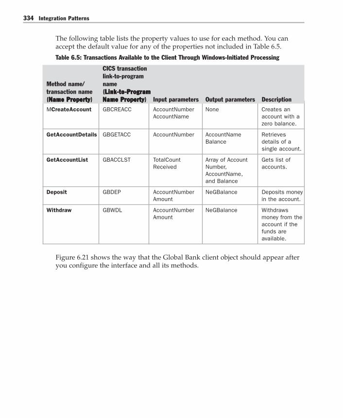
Integration Patterns334
The following table lists the property values to use for each method. You canaccept the default value for any of the properties not included in Table 6.5.
Table 6.5: Transactions Available to the Client Through Windows-Initiated Processing
CICS transactionlink-to-program
Method name/ nametransaction name (Link-to-ProgramLink-to-ProgramLink-to-ProgramLink-to-ProgramLink-to-Program(Name PropertyName PropertyName PropertyName PropertyName Property) Name PropertyName PropertyName PropertyName PropertyName Property) Input parameters Output parameters Description
MCreateAccount GBCREACC AccountNumber None Creates anAccountName account with a
zero balance.
GetAccountDetails GBGETACC AccountNumber AccountName RetrievesBalance details of a
single account.
GetAccountList GBACCLST TotalCount Array of Account Gets list ofReceived Number, accounts.
AccountName,and Balance
Deposit GBDEP AccountNumber NeGBalance Deposits moneyAmount in the account.
Withdraw GBWDL AccountNumber NeGBalance WithdrawsAmount money from the
account if thefunds areavailable.
Figure 6.21 shows the way that the Global Bank client object should appear afteryou configure the interface and all its methods.

Chapter 6: Additional Integration Patterns 335
Figure 6.21Global Bank client object with methods configured
4. Add the method parameters. The method parameters establish a mappingbetween the parameter types in the .NET Framework environment and theCOBOL data types in the mainframe environment. Add the method parametersfor each transaction according to the information in Table 6.6.

Integration Patterns336
Table 6.6: Global Bank Method Parameters
.NETInput/ Framework
Transaction Input parameters output data type COBOL data type
CreateAccount AccountNumber Input Decimal PIC S9(n)V9(n) COMP-3
CreateAccount AccountName Input String PIC X(n)
GetAccountDetails AccountNumber Input Decimal PIC S9(n)V9(n) COMP-3
GetAccountDetails AccountName Output String PIC X(n)
GetAccountDetails Balance Output Decimal PIC S9(n)V9(n) COMP-3
GetAccountList TotalCountReceived Input Integer PIC S9(n) COMP
GetAccountList Array of Output Decimal, PIC S9(n)V9(n)AccountNumber, String, COMP-3, PIC X(n),AccountName, Deciman PIC S9(n)V9(n) COMP-3and Balance
Deposit AccountNumber Input Decimal PIC S9(n)V9(n) COMP-3
Deposit Amount Input Decimal PIC S9(n)V9(n) COMP-3
Deposit NewBalance Output Decimal PIC S9(n)V9(n) COMP-3
Withdraw AccountNumber Input Decimal PIC S9(n)V9(n) COMP-3Amount
Figure 6.22 shows the way that the Global Bank client object should appear afteryou configure the method parameters.
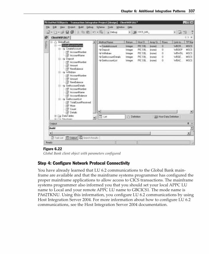
Chapter 6: Additional Integration Patterns 337
Figure 6.22Global Bank client object with parameters configured
Step 4: Configure Network Protocol ConnectivityYou have already learned that LU 6.2 communications to the Global Bank main-frame are available and that the mainframe systems programmer has configured theproper mainframe applications to allow access to CICS transactions. The mainframesystems programmer also informed you that you should set your local APPC LUname to Local and your remote APPC LU name to GBCICS1. The mode name isPA62TKNU. Using this information, you configure LU 6.2 communications by usingHost Integration Server 2004. For more information about how to configure LU 6.2communications, see the Host Integration Server 2004 documentation.
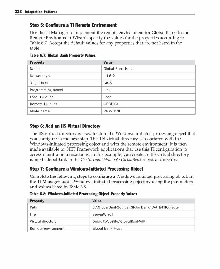
Integration Patterns338
Step 5: Configure a TI Remote EnvironmentUse the TI Manager to implement the remote environment for Global Bank. In theRemote Environment Wizard, specify the values for the properties according toTable 6.7. Accept the default values for any properties that are not listed in thetable.
Table 6.7: Global Bank Property Values
Property Value
Name Global Bank Host
Network type LU 6.2
Target host CICS
Programming model Link
Local LU alias Local
Remote LU alias GBCICS1
Mode name PA62TKNU
Step 6: Add an IIS Virtual DirectoryThe IIS virtual directory is used to store the Windows-initiated processing object thatyou configure in the next step. This IIS virtual directory is associated with theWindows-initiated processing object and with the remote environment. It is thenmade available to .NET Framework applications that use this TI configuration toaccess mainframe transactions. In this example, you create an IIS virtual directorynamed GlobalBank in the C:\Inetpub\Wwroot\GlobalBank physical directory.
Step 7: Configure a Windows-Initiated Processing ObjectComplete the following steps to configure a Windows-initiated processing object. Inthe TI Manager, add a Windows-initiated processing object by using the parametersand values listed in Table 6.8.
Table 6.8: Windows-Initiated Processing Object Property Values
Property Value
Path C:\GlobalBankSource\GlobalBank\DotNetTIObjects
File ServerWIP.dll
Virtual directory DefaultWebSite/GlobalBankWIP
Remote environment Global Bank Host

Chapter 6: Additional Integration Patterns 339
Step 8: Implement a .NET Framework Client ApplicationAt this point, TI has been configured to provide access to the CICS mainframetransactions. All that is left is to develop the .NET Framework client application thatinvokes the mainframe transactions.
Resulting ContextThe Gateway implementation described here results in the following benefits andliabilities:
Benefits● Reduced complexity. The gateway encapsulates data and protocol translations
required to use the account management system.● Reduced redevelopment efforts. Business logic that already exists on the main-
frame transactions does not have to be redeveloped in the .NET Frameworkenvironment.
● Reduced need for retraining. .NET Framework developers do not have tobecome familiar with CICS or COBOL to use the existing mainframe transactions.
Liabilities● Increased maintenance effort. Host Integration Server 2004 is an additional
system that must be maintained.● Lack of support for two-phase commit transactions when using .NET Frame-
work client libraries. The .NET Framework client library used in this scenariodoes not support two-phase commit transactions. Many organizations rely ontwo-phase commit transactions for day-to-day operations, so this configurationmay not suit them. Instead, they would have to use a COM type library that doessupport two-phase commit transactions.
TestsTo fully test the deployment of TI in this scenario, you must have access to a main-frame computer that is running the proper CICS transactions. However, you can usethe TI host-initiated processing capabilities to simulate this access. For instructionson how to configure this simulation, see the Host Integration Server 2004 onlinedocumentation at http://www.microsoft.com/hiserver/techinfo/productdoc/default.asp.


7Project Notebook
“A business architecture is just an instruction set for extracting value. To extract value, abusiness must first create value for its customers; then extract some of the customertransaction value for itself.” — Richard Sears, engineer and entrepreneur
While constructing the baseline architecture for Global Bank, the architecture teamcreated numerous artifacts ranging in scope from business process models to execut-able bits. The team created these artifacts so that they could understand the businesswith sufficient clarity to create a technical architecture that would meet the needs ofthe business.
As they designed the technical architecture for Global Bank, they wanted to takeadvantage of reusable design elements (patterns) to mitigate technical risk and makethe project more predictable. In addition, they knew that these patterns embodieddesign principles that would make it easier to evolve the architecture as the needs ofthe business changed over time. They wanted to take advantage of this extensibilityafter the system was delivered to lower the cost of new application development inthe future.
This chapter presents some of the artifacts that the team produces while designingthe baseline architecture. It starts with an overview of Global Bank’s businessenvironment, and then describes the viewpoints of five key business stakeholders.These viewpoints are captured in a set of models, which trace a path from businessrequirements to the technical solution. The chapter also presents some pattern-driven design models that capture the team’s use of patterns during the process.

Integration Patterns342
Interpreting the ArtifactsThis chapter presents Global Bank team artifacts in a logical top-down progression,by starting with the high-level organizational processes and then disassemblingthese processes in progressive levels of detail. The order in which the chapter pre-sents these artifacts does not, however, reflect the order in which the team producedthem. The team produced the artifacts through an iterative process — building firstcut approximations and then progressively refining them in subsequent iterations.They are presented here in logical order only to enhance readability.
The scenario presented in this book is intentionally incomplete. And although theartifacts presented here were used to build out an actual running system, it is impor-tant to remember that both Global Bank and the scenario portrayed are fictitious.They are intended only to demonstrate the application of patterns to the problems ofintegration within a representative enterprise scenario.
Let’s examine the overall business context in more detail.
Global Bank Business ContextGlobal Bank is a midsize, traditional bank that has acquired a complete range offinancial services capabilities through a series of acquisitions. The bank currentlyhas a limited online presence that is fragmented across its various divisions. As partof its expansion strategy, Global Bank has decided to innovate in the online bankingmarket by providing a host of value-added services on top of a fully integratedfinancial management capability. Some banks currently offer, or are developing thecapability to offer, integrated online banking across all accounts (such as savings,checking, and credit cards). But no other bank offers a full range of value-addedservices such as financial advice, financial analysis and planning, and tax planningand filing. In addition, Global Bank has not seen the synergies it anticipated fromoffering a complete line of products. This lack of synergy is caused by its inability toeffectively cross-sell based upon existing relationships and customer knowledge.
Convergence in the Banking IndustryIn the late 1990s, the United States Congress began the process of deregulating thefinancial services industry. The Depression-era regulations restricted what servicescould be provided by specific types of financial services companies. Banking couldonly provide banking products and insurance companies could only provide insur-ance products. The deregulation of the industry had the effect of removing the legalbarriers between various product types and between the companies that providedthem. This triggered a mergers and acquisitions frenzy to broaden service offeringportfolios.

Chapter 7: Project Notebook 343
Because he is familiar with the notion of profit patterns, the CEO of Global Bankquickly recognizes a particular pattern unfolding within his industry. He stronglybelieves that this Convergence pattern [Slywotsky99] will not only impact the globaland national banks, but the whole industry.
The Convergence pattern describes the phenomenon in which businesses expandtheir offerings to related products and services along the value chain. Customersmay forsake traditional suppliers in search of higher value, if not lower price (forexample, the modern financial services industry). This complicates the market andpresents a challenge because you must meet the new market by expanding yourdeliveries, which takes you outside your expertise. Convergence occurs when suppli-ers do one or more of the following:● Expand up or down the value chain● Substitute new products in place of existing ones● Bundle products together
To apply the supplier Convergence pattern, you must do three things: first, success-fully promote your product offerings; second, emphasize the portions of the chainwhich command the highest perceived value and; third, upgrade your delivery ofthe lower value products. Convergence requires gaining access to the other aspects ofthe bundled product. This usually involves mergers and acquisitions. It is wise tojump into mergers and acquisition activity early, when the choice of business combi-nations is best.
Bundling products together also increases efficiency due to economies of scope. Thatis, the cost of performing multiple business functions simultaneously should proveto be more efficient than performing each business function independently, andtherefore drive down overall costs.
Applying the strategy of convergence, the CEO convinces the board of Global Bankto embark on a series of financial service acquisitions, which in effect creates amidsize, full-service financial company. To turn this strategy into concrete action, theCEO needs to charter several projects. For each one of these projects, there are keystakeholders, each with a unique viewpoint.
One of the key initiatives involves strengthening the bank’s online presence. Theonline channel is an effective means of adding new services at relatively low cost.With many customers using online checking and savings today, it will be easy tomove them to other value-added services if the bank can make the online serviceswork better together. A key new service is the addition of an online bill paymentfeature. Let’s take a closer look at the stakeholders in this initiative.

Integration Patterns344
Stakeholder ViewpointsThere are five key stakeholders for the online bill payment initiative: the Board ofDirectors, the Chief Executive Officer (CEO), the General Manager of BankingServices, the Director of Electronic Bill Presentment and Payment (EBPP), and theSupervisor of EBPP.
Board of Directors ViewpointThere are five members of the Board of Directors for Global Bank. One member is anexperienced executive within the financial services industry and the others comefrom other industries. Members of the board are elected by shareholders to overseemanagement of the company. In this capacity, the board meets every six weeks withGlobal Bank’s executive team to review operations and make critical decisions thataffect the future direction of the firm.
The board is primarily concerned with the overall assets within the bank, and howthese assets are used to create wealth. They want to understand what drives thereturn on capital invested and what the investment risks are.
The board is very interested in understanding how current and potential customersbenefit by doing business with Global Bank. They know that satisfied customers area key ingredient for any sustainable enterprise. For clarity and operational effective-ness, Global Bank’s value to customers is clearly stated in a series of value proposi-tions, one of which is for online services.
Value Proposition for Online ServicesGlobal Bank’s value proposition for online services is to provide an integrated,online financial portal for affluent clients that will enable them to view all of theirfinancial assets at once. From this integrated view, clients will be able to seamlesslyexecute all of their financial transactions including those associated with savingsand checking accounts, loans, stock trading, domestic and international bill paymentand funds transfer. Clients will use this portal to save their most precious commod-ity: time. Through efficient operations, the bank will be able to offer this capabilityto clients without irritating service fees for each transaction.
In addition to serving affluent clients, the bank will also serve mass market custom-ers with simplified services such as checking, savings, and mortgage origination.Customers will benefit from the intuitive user experience and integration with homemortgage loans and credit cards.
Providing this integrated service to customers will allow the bank to provide ahigher rate of return on assets than other banks. Focusing on high-net-worth indi-viduals means that the bank can manage more assets with fewer transactions. Fewertransactions result in lower total operations cost. Providing an integrated portal tocustomers enables effective cross selling from low margin service offerings (such as

Chapter 7: Project Notebook 345
savings accounts) to high margin service offerings (such as loan and portfoliomanagement services).
A compelling online user experience will drive adoption and attract new customers,including high-net-worth individuals and lower income, mass market accounts.Although the mass market accounts are less profitable, they will more than covercosts; the higher margins, however, will come from the wealthy individual segment.After the user experience is developed for high-end customers, it will be easy tooffer a reduced-service version for the mass market.
Capital ExpenditureDelivering on this value proposition requires significant capital investment in newcapabilities. In the past, technology investments have represented a high percentageof the bank’s capital expenses. The Board also considers technology investments tobe somewhat risky, due to the difficulty in predicting cost and schedule for bothcustom software development and system integration projects.
The Board wants better visibility into these projects at a high level. Recently, theChief Technical Officer (CTO) briefed the board on a major project and visuallypresented a set of decision points related to the proposed technical architecture. Thedecisions points he presented (shown later in this chapter in Figure 16) reflected aset of choices containing proven design elements assembled together in a cohesiveset. These elements were considered proven because they were harvested from othersoftware engineering projects and had withstood scrutiny from the software designcommunity. Creating a design based on these elements would mitigate some of theproject’s risk, making it more predictable. Of course, he explained, just using thesedesign elements (patterns) was no guarantee of success — the real success woulddepend on the skill and experience of the team and how they implemented theactual system.
As the CTO presented, he talked through some of the design elements such asgateways to credit bureaus and message brokers. Although the board was notparticularly technical, they got a sense of how the capabilities they were investing inwere realized with technology at a high level. This understanding, and the vocabu-lary that went with it, allowed them to ask clarifying questions about the approachwithout getting bogged down with lower-level details. It also helped them to see theconnection between the firm’s value propositions and technical investments, andthey expected this alignment to occur at various levels within the organization. Theprimary person they held accountable for driving this alignment throughout theorganization is the CEO.

Integration Patterns346
Chief Executive OfficerThe CEO perspective focuses on defining the strategy and formulating a strategicportfolio of initiatives to take advantage of, or defend against, the opportunities andthreats in the marketplace. The CEO of Global Bank defines a strategy and a set ofinitiatives that reflects his firm’s approach in the financial services sector — a sectorthat is currently experiencing significant growth.
Evaluating the Current SituationDriven by the explosive growth in home refinancing activity and the improvedmargins of full-service financial institutions, the banking industry is one of the fewbright spots in this slow-growth economy. The CEO of Global Bank, however, hasbeen frustrated by his company’s lackluster profit margins and anemic growth inrevenues. If the bank doesn’t correct these trends quickly, its shareholders may missout on the impressive returns of the rest of the industry.
Global Bank has been suffering from the growth in customer churn, which is definedas the loss of old customers and the acquisition of new customers where the netchange in number of customers is close to zero. Customer churn has raised thebank’s customer acquisition cost by 3 percent, which is a substantial increase. Theloss in customers is believed to be caused by the lack of awareness and the inconve-nient access to the firm’s full suite of services offerings. Especially troubling is theloss of high-net-worth individuals. Many studies show that this particular marketsegment is the most likely to use fully integrated financial services; this segmentalso creates, on average, a 6 percent higher rate of profitability than other marketsegments.
Figure 7.1 correlates the bank’s current portfolio allocation against average growthand profitability rates for the industry.

Chapter 7: Project Notebook 347
14%
B
CM
CN
F
12%
10%
8%
6%
4%
2%40%
10%
20%
20%
10%
0%
-5%
Savings
"As-Is" Portfolio vs Industry
Industry Profitability
Indu
stry
Gro
wth
Rat
e
0% 5% 10% 15%
S
S
Commercial LendingCM
BrokerageB
Financial PlanningF
Consumer LendingCN
Figure 7.1Initial allocation of Global Bank portfolio, according to service type
The bubbles in Figure 7.1 represent the share of the bank’s portfolio. Current portfo-lio allocation shows that more than two-thirds of the bank’s portfolio is investedinto savings, the lowest-growth and lowest-profit of all service offerings based oncurrent industry average growth and returns. Only 20 percent of the bank’s portfoliois allocated to consumer lending, which is a high growth/high profit category. Table7.1 shows the specific numbers associated with Figure 7.1.

Integration Patterns348
Table 7.1: Global Bank Portfolio Compared to Average Profitability and Growth Rates for theIndustry Segment
Services Average profitability Average growth rate Share of Global Bankfor the industry for the industry portfoliosegment
Savings 1% 2% 40%
Commercial lending 3% 8% 20%
Consumer lending 4% 12% 20%
Brokerage 7% 3% 10%
Financial planning 9% 7% 10%
Formulating a StrategyThe CEO wants to change the bank’s portfolio mix so that a higher percentage of theportfolio is in high growth and high profit categories. Specifically, the CEO believesthat the bank could increase deposits, reduce churn, and dramatically increase loanorigination by offering an integrated savings, checking, and mortgage solution.
There are four critical success factors for this initiative:● Make the bank’s complete suite of services easily accessible, both online and
offline.● Make the online services work better together to provide a richer, more inte-
grated experience between offerings.● Build awareness of the suite of services, both online and offline.● Attract and retain high-net-worth individuals.
The CEO believes that the first two measures could reduce churn costs by 2 percentand increase loan origination to 40 percent of their business portfolio. The multipleentry points and the exposure of the bank’s services to a wider array of customerswill help drive the growth in these segments of the portfolio. Based on estimatedcustomer value and acquisition costs, he projects that focusing on attracting andretaining high-net-worth individuals will affect profit margins by as much as 10percent.

Chapter 7: Project Notebook 349
The overall strategy will be to bundle higher-profit services such as consumerlending (also known as mortgage) together with the basics (savings) to change theportfolio mix to things that are more profitable industry wide. By doing so, the CEObelieves that he can increase customer loyalty and increase the cost the customerwould incur to switch banks (switching costs). He also believes this integratedapproach has the potential to increase the very profitable financial planning offeringto 20 percent of the bank’s portfolio. Figure 7.2 shows the CEO’s projected portfolioallocation after the successful execution of these key initiatives.
14%
B
CMF
12%
10%
8%
6%
4%
2% 10%
10%
20%
40%
20%
0%
-5%
Savings
"To Be" Portfolio vs Industry
Industry Profitability
Indu
stry
Gro
wth
Rat
e
0% 5% 10% 15%
S
S
Commercial LendingCM
BrokerageB
Financial PlanningF
Consumer LendingCN
CN
Figure 7.2Projected allocation of Global Bank portfolio, after convergence

Integration Patterns350
Table 7.2 compares Global Bank’s projected portfolio to average industry segmentgrowth rates and profitability after the successful execution of the consolidationinitiative.
Table 7.2: Global Bank Projected Portfolio Compared to Average Profitability and Growth Ratesfor the Industry Segment
Services Average profitability Average growth Share of Global Bankfor the industry rate for the industry portfoliosegment
Savings 1% 2% 10%
Commercial lending 3% 8% 20%
Consumer lending 4% 12% 40%
Brokerage 7% 3% 10%
Financial planning 9% 7% 20%
The CEO realizes that the firm needs to bundle together services that may neverhave been previously integrated. Given his convergence strategy, he also knows thatthe firm must aggressively and quickly acquire new capabilities. He expects topursue partnering agreements, mergers, and acquisitions as soon as possible, butknows from past experience how challenging the integration issues could be. He isalso aware of high-level service-oriented-architecture concepts that he’s learnedfrom his CTO and wonders if they might be applicable here. If so, they may have animpact on the execution of his strategy.
To move forward with this initiative, the CEO calls a two-day working session withbank executives who report directly to him. The session includes both general andadministrative executive leadership. The CEO knows that this initiative requiressignificant capital investment and that the organization must focus on deliveringas much customer value as possible for each dollar invested. To start, he will workwith the General Manager of Banking to shape a more detailed customer valueproposition.
Chapter 7: Project Notebook 351
General Manager of BankingDuring the working session, the CEO briefs the service-line general managers,including the General Manager (GM) of Banking about his plan for dealing withconvergence. To act on this plan, two teams are formed: banking services andfinancial planning services. The teams are organized as follows:● Banking services. The GM of Banking will lead a team to create a service bundle
that will integrate checking, savings, bill payment, and mortgage loan origina-tion.
● Financial planning services. The GM of Financial Planning Services will lead ateam to focus on creating a service bundle that will integrate financial planning,non-mortgage lending, investing, and insurance.
Other executives, including the CTO, and the Chief Financial Officer (CFO), areexpected to support and report into each team. Each team is expected to find areasof synergy between service lines to enable cross-selling convenience and compatibil-ity. The teams must also identify and support all real competitive differentiators.
The rest of the Global Bank scenario described here and earlier in Chapter 2, “UsingPatterns to Design the Baseline Architecture,” focuses on the effort to create thebanking services bundle.
Banking Services BundleThe GM for Banking Services is excited about the prospect of offering a more robustset of services to the general public. She believes the direct impact of the integratedservice bundle will be a doubling of the consumer loan portfolio.
Zeroing in on the changes she wants to affect, the GM creates two visual models tocommunicate with her team. Figure 7.3 shows the current “as-is” situation with 40percent of the firm’s service offerings in savings, which is a low growth and lowprofit category.

Integration Patterns352
14%
CM
12%
10%
8%
6%
4%
2%
20%
CN20%
0%
Savings
"As-Is" Portfolio vs Industry
Industry Profitability
Indu
stry
Gro
wth
Rat
e
0% 2% 4% 6%
S
Commercial LendingCM
Consumer LendingCN
40%S
Figure 7.3Current portfolio allocation of services in the banking services bundle
Figure 7.4 shows the desired “to-be” situation after changes have been implemented.Notice that the portfolio has shifted, moving the majority of the service offerings tohigh growth and high profit categories.

Chapter 7: Project Notebook 353
14%
CM
12%
10%
8%
6%
4%
2%
20%
40%
0%
Savings
"To Be" Portfolio vs Industry
Industry Profitability
Indu
stry
Gro
wth
Rat
e
0% 2% 4% 6%
S
Commercial LendingCM
Consumer LendingCN
10%S
CN
Figure 7.4Projected portfolio allocation of services in the banking services bundle, after changes
The GM believes that the critical success factor to attracting and retaining newcustomers rests chiefly on the success of their bill payment service. Studies showthat as customers successfully use online bill payment (which is the next logicalservice after online savings and checking services) they are much more likely toexplore and use additional value-added services. From there, the GM believes thatcustomers will naturally turn to Global Bank for loans.

Integration Patterns354
The GM knows she must collaborate with two key members of the team. First, shemust work with the CTO to smoothly integrate the value-added services with onlinebill payment. Next, she knows the online bill payment feature would require highlevel involvement of the electronic bill presentment and payment department. Shewould need to work closely with the director of that department.
Director of Electronic Bill Presentment and PaymentThe Director of Electronic Bill Presentment and Payment (EBPP) is very excitedabout the prospect of the bank investing strongly in his area. Currently, only 3percent of the bank’s customers use online banking services. He believes that with asimilar look and feel to the checking and savings offering, the online bill paymentservice will help increase the use of the online banking services to over 20 percent ofthe bank’s customers.
To reach this 20 percent usage target, the director has identified the followingrequirements that are critical to the success of the system:● Similar user experience to the current checking and savings site. More specifi-
cally, the number of key strokes required to complete a bill payment transactionmust be less than or equal to the number required to complete a checking andsavings transaction.
● The time required to add a new payee to the system must be minimized. Thetime needed to add payees (known as billers) to the system was expected to be akey barrier to adoption. Making this experience quick and painless would makethe service very compelling for customers to use.
● Bill payment must be prominent on the Global Bank portal page. The billpayment service must be in an inviting and logical location on the portal mainpage (in relation to the checking and savings page).
To achieve these requirements, he would have to collaborate closely with the archi-tects, designers, and analysts from the CTO’s team. He would also have to workclosely with the supervisor of electronic bill presentment and payment operations.Behind the user interface, it is the supervisor who has detailed knowledge of theprocesses and systems needed to make this system operational.
Chapter 7: Project Notebook 355
Electronic Bill Presentment and Payment SupervisorThe Supervisor of Electronic Bill Presentment and Payment Operations has justlearned of the new strategic focus on EBPP as a key capability in the overall bankstrategy and he is a bit concerned. The EBPP capability must be enhanced in severalways to meet the bank’s growth objectives.
The focus of the Director of EBPP is primarily on the user experience and how thepresentation and navigation of the EBPP functions should be similar to the existingchecking and savings functionality. The main underlying issue for EBPP operations,however, is how to integrate the existing systems to provide a seamless experiencewithout tightly coupling all of the systems together. In the past, the Supervisor ofEBPP has been frustrated by systems that could not be replaced or changed becauseof tight interdependencies between systems. He wants to avoid that frustration inthe future.
To meet its objective, the EBPP implementation must also streamline the addition ofnew billers and simplify the integration and processing for existing billers. Thissimplification will help control the operations costs of the EBPP system. One of thesupervisor’s goals is to automate the entire EBPP process, including the subscriptionmanagement of EBPP users. The current manual subscription management processcan take as long as 30 days to enroll a new EBPP participant. The manager considersthis 30-day process to be a loss in revenue, as well as a barrier to adoption.
From Business Scenario to Technical SolutionThe technical team at Global Bank now has enough business context to start theirtechnical planning sessions. Now they need a way to organize their thinking aboutthe overall enterprise. Although there are many valid models that they could use,the team started with an enterprise architecture stack as shown in Figure 7.5.

Integration Patterns356
Business Architecture
Integration Architecture
Application Architecture
Operational Architecture
Development Architecture
Figure 7.5Enterprise architecture stack used by the Global Bank technical team
At the top of the stack is the business architecture, which captures the resources,processes, goals, and rules that the enterprise uses to generate revenue and profit.Underneath the business architecture are several levels of technical architecture thattogether enable the enterprise to realize its business architecture.
After business architecture, the next level on the stack is the integration architecture.This architecture describes an integrated portfolio of applications that support thebusiness architecture. Underneath the integration architecture is the applicationarchitecture. For each application described in the integration architecture, there is adetailed description of the application in the application architecture. This includes(but is not limited to) platform infrastructure components such as applicationservers, Web servers, and databases.
After an instance of an application is built, it must be deployed into production,operated, and maintained. These concerns are described in the operational architec-ture. Finally, the development architecture describes how teams build instances ofapplications and integrations. This development level includes (but is not limited to)developer and lifecycle tools, build environments, and processes.
As teams make decisions within each level of architecture, they should verifywhether they directly support the enterprise’s value proposition. To make verydetailed decisions about architecture, it is helpful to have a more granular perspec-tive than architectural levels provide — such as a perspective based onviewpoints.

Chapter 7: Project Notebook 357
Viewpoints Within the Enterprise ArchitectureAlthough the enterprise architecture stack in Figure 5 is useful to organize andclassify initial architectural concerns, the team needed a more granular classificationscheme. The team realized that the artifacts they produced to describe their systemswould differ according to discrete viewpoints. A viewpoint is really just a lens intothe enterprise, and from the perspective of these lenses, many snapshots, or picturesmight be taken. They decided to organize these viewpoints from the perspective ofvarious roles within the enterprise. Figure 7.6 shows three layers of the resultingmodel, which added some of the roles identified for the business, integration, andapplication architecture levels.
Business Architecture
Chief Executive Officer
General Manager
Process Owner
Process Worker
Integration ArchitectureEnterprise Architect
Designer
Developer
Application Architecture
Enterprise Architect
Architect
Designer
Developer
Figure 7.6Levels and viewpoints within the architecture stack
Figure 7.6 concentrates on the three layers of the architecture stack that are the focusof this guide. The business architecture includes the views of key stakeholders aswell those involved with business processes. The focus on process is important,because processes are key interfaces between people and systems. Processes alsoenable the enterprise to complete the work from which it derives revenue.
In the areas of application and integration, viewpoints are organized according totraditional information technology roles. These viewpoints reflect the differentconcerns of various roles. For example, as a team builds an application an architect’sconcerns will be different from a developer’s concerns.
Now that the team had a model with which to organize their approach, they builtmore detailed visual models that captured their stakeholder concerns.

Integration Patterns358
Business Architecture ViewsTo model the business architecture views, they used the Erikkson/Penker BusinessExtensions to the Unified Modeling Language (UML) [Erikkson2000]. These exten-sions to the UML provide stereotypes for business concepts such as processes,events, resources (including people), goals, and rules.
To draw these models, they used the Microsoft Office Visio® Professional 2003drawing and diagramming software as their tool of choice. They used a templatecreated by Pavel Hruby (available at http://www.phruby.com/stencildownload.html) thatcontains more of the UML stereotypes than the standard Visio templates. Usingthese tools, the team created a series of views of enterprise processes.
CEO’s ViewThe first model they created was the highest-level enterprise view, which reflectedthe CEO’s viewpoint. Figure 7.7 shows this CEO view of the business architecture.

Chapter 7: Project Notebook 359
<<enterprise process portfolio>>
Global Bank
Customer Clearinghouse Brokerage
<<creates>>
<<supply>>
Federal
Reserve
<<resources>>
<<physical>>
Output
<<physical>>
Capital
<<information>>
Strategy
<<business
service>>
Basic Banking
<<business
service>>
Insuring
<<business
service>>
Investing
<<mission>> <<vision>><<guiding
principles>>
<<guides>>
<<guides>><<guides>>
<<information>>
Regulation
Credit
Bureau
Third-Party
Services
Other Financial
Institutions
Incomplete
Incomplete
<<people>>
<<control>>
<<achieves>>
<<goal>>
Process Goal:
Quantitative Goal
<<goal>>
Process Goal:
Qualitative Goal<<achieves>>
<<business
service>>
Lending
<<business
service>>
Sales,
General, and
Administrative
Figure 7.7CEO’s view of the high-level enterprise processes
In Figure 7.7, resources on the left are inputs into the bank. The elements on the topguide and constrain the activities of the bank, while the center contains groups ofprocesses needed to run the bank. Beneath the Global Bank box are the entities withwhich the bank collaborates. The bank’s output is modeled on the right.
Notice the core process groups within the bank include basic banking, insuring,lending, investing, and sales, general, and administrative (SGA). The processes ofinterest to the online bank initiative are in the basic banking group, headed by theGeneral Manager of Banking. Let’s now look into this group (shown in gray) inmore detail.

Integration Patterns360
General Manager’s ViewFor the basic banking group of processes, the team created a model that describesthe bank from the GM of Banking’s view, as shown in Figure 7.8.
<<business service>>
Basic Banking - Commercial
Customer
<<creates>>
<<supply>>
<<resources>>
<<abstract>>
Output
<<physical>>
Capital
<<abstract>>
Banking
Strategy
<<mission>> <<vision>><<guiding
principles>>
<<guides>><<guides>> <<guides>>
<<information>>
Banking
Regulation
<<business service>>
Basic Banking - Consumer
<<business service>>
Consumer Lending
<<business service>>
Consumer Banking
Other
Financial
Institutions
Credit
Bureau
Incomplete
Incomplete
<<people>>
<<control>>
<<goal>>
Process
Goal:
Quantitative
Goal
<<goal>>
Process
Goal:
Qualitative
Goal
<<business
service>>
Payment
Processing
<<business
service>>
Electronic Bill
Presentment
and Payment
(Online Bill
Payment)
<<business service>>
Loan Servicing
<<business
service>>
Account
Management
<<business
service>>
Loan
Origination
<<achieves>>
<<achieves>>
<<business
service>>
Electronic
Funds Transfer
<<business
service>>
Cash
Management
(Checking and
Savings)
<<business
service>>
Card Services
achieves>><<
<<achieves>>
Figure 7.8General Manager of Banking’s high-level view of processes
Similar to the CEO’s view, this view shows resource inputs on the left, guidelinesand constraints on the top, outputs on the right, and entities (collaborators) onthe bottom. Notice that basic banking includes both consumer (foreground) and
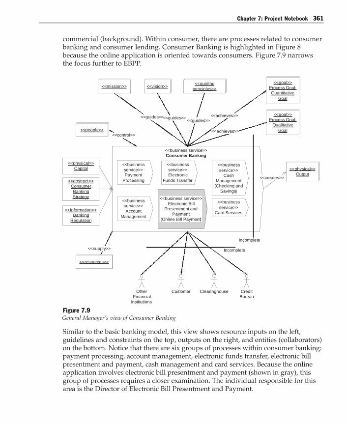
Chapter 7: Project Notebook 361
commercial (background). Within consumer, there are processes related to consumerbanking and consumer lending. Consumer Banking is highlighted in Figure 8because the online application is oriented towards consumers. Figure 7.9 narrowsthe focus further to EBPP.
<<business service>>
Consumer Banking
<<creates>>
<<physical>>
Output
<<business
service>>
Cash
Management
(Checking and
Savings)
<<business service>>
Electronic Bill
Presentment and
Payment
(Online Bill Payment)
Customer
<<goal>>
Process Goal:
Quantitative
Goal
<<achieves>>
<<mission>> <<vision>><<guiding
principles>>
<<guides>><<guides>><<guides>>
<<physical>>
Capital
<<abstract>>
Consumer
Banking
Strategy
<<information>>
Banking
Regulation
Incomplete
Credit
Bureau
ClearinghouseOther
Financial
Institutions
<<supply>>
<<resources>>
<<people>>
<<control>>
<<goal>>
Process Goal:
Qualitative
Goal<<achieves>>
<<business
service>>
Payment
Processing
<<business
service>>
Account
Management
<<business
service>>
Electronic
Funds Transfer
<<business
service>>
Card Services
Incomplete
Figure 7.9General Manager’s view of Consumer Banking
Similar to the basic banking model, this view shows resource inputs on the left,guidelines and constraints on the top, outputs on the right, and entities (collaborators)on the bottom. Notice that there are six groups of processes within consumer banking:payment processing, account management, electronic funds transfer, electronic billpresentment and payment, cash management and card services. Because the onlineapplication involves electronic bill presentment and payment (shown in gray), thisgroup of processes requires a closer examination. The individual responsible for thisarea is the Director of Electronic Bill Presentment and Payment.
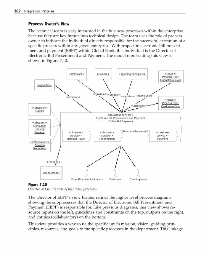
Integration Patterns362
Process Owner’s ViewThe technical team is very interested in the business processes within the enterprisebecause they are key inputs into technical design. The team uses the role of processowner to indicate the individual directly responsible for the successful execution of aspecific process within any given enterprise. With respect to electronic bill present-ment and payment (EBPP) within Global Bank, this individual is the Director ofElectronic Bill Presentment and Payment. The model representing this view isshown in Figure 7.10.
<<business service>>
Electronic Bill Presentment and Payment
(Online Bill Payment)
<<goal>>
Process Goal:
Quantitative Goal
<<achieves>>
<<goal>>
Process Goal:
Qualitative Goal<<achieves>>
<<business
service>>
Maintain Payee
<<business
service>>
Presentment
<<business
service>>
Payment
[Payment Requested]
<<physical>>
Capital
<<abstract>>
Consumer
Banking
Strategy
<<information>>
Banking
Regulation
<<supply>>
<<resources>>
Customer ClearinghouseOther Financial Institutions
<<mission>> <<vision>> <<guiding principles>>
<<guides>><<guides>><<guides>>
<<people>>
<<control>>
Figure 7.10Director of EBPP’s view of high-level processes
The Director of EBPP’s view further refines the higher level process diagramsshowing the subprocesses that the Director of Electronic Bill Presentment andPayment (EBPP) is responsible for. Like previous diagrams, this view shows re-source inputs on the left, guidelines and constraints on the top, outputs on the right,and entities (collaborators) on the bottom.
This view provides a way to tie the specific unit’s mission, vision, guiding prin-ciples, resources, and goals to the specific processes in the department. This linkage

Chapter 7: Project Notebook 363
allows both the business owner and the technical architects to evaluate specific cost-benefit tradeoffs for the design and implementation based on the business value andgoals while maintaining traceability to the organizational guidelines and goals.
This view is helpful because it breaks down processes to granular subprocesses, andapproaches the level needed for detailed technical analysis. However, subprocessesare not granular enough. The team needs to identify the level at which a person orsystem (actor) interacts directly with another system. This actor/system boundary isthe level which use cases describe, and the person who interacts directly with thesystem to perform part or all of a business process is called a process worker. Oneimportant process worker in Global Bank is the EBPP Supervisor.
Process Worker’s ViewThe EBPP Supervisor works with his team to review the Director of EBPP’s view(shown in Figure 7.10) and identify all of the related use cases as shown in Figure7.11. For each use case, a description is created that includes preconditions, post-conditions and the steps involved in the use case. Steps are included for normal andexception scenarios.

Integration Patterns364
Notification Package
Bill Payment
System Package
Customer
Package
Customer
Sign Up for EBPP
Get Potential EBPP
Payees
Get Current EBPP
Payees
Add EBPP Payee
Remove EBPP
Payee
View Scheduled
Payments
Request Bill
Payment
Quit EBPP
Payee
Register as EBPP
Payee
Bill Payment
System
Submit Bills for
EBPP Customers
Send Notifications
Bills Due
EBPP
Administrator
Notification
System
Execute Scheduled
Payments
Register Customer
with Payee
Manage
Notification Profile
Add Notification
Event
New Bills
Get Customer Data
Update Bill Status
Receive Payment
Response
Figure 7.11Significant EBPP use cases
The use cases outlined in gray are key parts of the online bill payment application.To further define these use cases, the team creates activity diagrams that show thedetails needed to realize the use case, such as conditional branching, transitions,forks, and joins.

Chapter 7: Project Notebook 365
Integration Architecture ViewsAlthough architects were involved in understanding and modeling the previousviews, more analysis is needed before the team can design a technical solution thatmeets the needs of the bank. Before the team spends time designing a technicalsolution, they want to make sure that the business processes that they want toautomate will add as much value as possible to the enterprise. To determine thisvalue, the architects work with business analysts to examine the business processesin more detail.
Process Value AnalysisBefore rushing into defining requirements for the technical solution, the team wantsto make sure that the processes they are automating are aligned with the enterprise’soverall value proposition. To do so, they analyze each significant use case andbusiness process according to the value it adds to the enterprise. To quantify value,they estimate the number of full-time employees and the cycle time needed for eachstep of the most important processes. They categorize each step as a value-add forthe customer, a value-add for the business, or not a value-add.
The team tunes their processes to be as efficient as possible given the enterprise’svalue proposition. Working with the executive team where necessary, they are ableto improve the firm’s overall business process design and thereby avoid automatinginefficient processes with technology. Also, during this analysis process they identifyuse cases that greatly enable the customer value proposition yet are inexpensive toimplement. These items become high priority work items in early iterations. Afterthey create a set of prioritized and well-designed processes expressed as use cases,they consider how to realize these use cases. A key step in the realization of theseuse cases is to identify the appropriate logical services.
Logical ServicesThe team reviews the EBPP process groups and identifies use cases for each processgroup. They step through each use case and design a collaboration of services thatallows them to realize each use case. As they see multiple use cases using a particu-lar service, they factor the service interface to make it as flat and stable as possible.They know that once they create these published interfaces, they will be much moredifficult to change in the future. Therefore, time spent factoring these interfaces nowwill pay off with fewer versioning headaches later and allow them to support moreuse cases with each service. To communicate these relationships, they create theassembly line drawing in Figure 7.12.

Integration Patterns366
Account Services
<<business service>>
Electronic Bill Presentment and Payment
(Online Bill Payment)
<<goal>>
Process Goal:
Quantitative Goal
<<achieves>>
<<goal>>
Process Goal:
Qualitative Goal
<<achieves>>
Profile Services
Payment Services
<<business
service>>
Maintain Payee
<<business
service>>
Presentment
<<business
service>>
Payment
Sc
he
du
le P
ay
me
nt
Ex
ecu
te S
ch
ed
ule
d P
ay
me
nt
Re
ce
ive
Pa
ym
en
t R
es
po
ns
e
Ge
t C
usto
me
r D
ata
[Payment
Requested]
Ad
d/R
em
ove
Pa
ye
es
Ge
t C
urr
en
t P
aye
es
Ge
t C
urr
en
t B
ills
Ge
t C
usto
me
r D
ata
Vie
w S
ch
ed
ule
d P
ay
me
nts
Ge
t B
ill D
ata
Get
Acco
un
t D
ata
Get
Acco
un
t D
ata
Ge
t A
cco
un
t D
ata
Figure 7.12Assembly line drawing showing a candidate set of logical services for Global Bank
At the top of the assembly line diagram are the groups of processes within EBPP andtheir associated use cases. On the left side of the diagram are candidate logicalservices that will play a role in realizing the intersecting use cases. By identifyingsets of use cases that must interact with a specific service, it is easier to designservices that eliminate duplication and are more extensible.

Chapter 7: Project Notebook 367
With a set of prioritized use cases and an initial set of logical services needed torealize those use cases, the team then spends time deciding how to allocate theselogical services to physical servers.
Technical ArchitectureTo allocate logical services to physical servers, the team starts by reviewing theenterprise’s existing technical architecture. They want to use these existing invest-ments as much as possible, and extend them to take advantage of commercialinfrastructure platform components such as Web servers, databases, and integrationservers.
Taking all of these factors and constraints into consideration, they arrive at a techni-cal architecture as shown in Figure 7.13.

Integration Patterns368
DataFirewall
External Partner(SWIFT)
External Partner(Manual Fulfillment)
Customer
SMTP IntegrationServer
Web Server
Firewall
IntegrationServer
NetworkedBank
System
NetworkedBank
System
Payment DirectoryServices
GatewayService
Gateway
Mainframe
CRM
Ethernet
Ethernet
Firewall
Remote Data Center
Data
Figure 7.13Global Bank’s initial technical architecture

Chapter 7: Project Notebook 369
Given the system use cases and a first cut technical architecture, the team is able toidentify some areas that represent high technical risks for the project. They want tomake sure and tackle these areas first so they can “retire” these risks early in theproject life cycle. To exercise these areas, they identify a set of architecturally signifi-cant use cases.
Architecturally Significant Use CasesAs described in Chapter 2, “Using Patterns to Design the Baseline Architecture,” thearchitecturally significant use cases for Global Bank include the following:● Schedule Payments● View Scheduled Payments● Execute Scheduled Payment● Receive Payment Response● Add Payee
For each one of these use cases, the team identifies how a set of server processes andnodes collaborate to realize each use case. They capture this high-level interactionwith collaboration diagrams. In addition to collaboration diagrams, the team alsocreates a “port and wire” style model that shows service encapsulation and commu-nication through ports, as shown in Chapter 2.
With high-level collaborations defined for server processes and nodes, the teamneeds to refine these collaborations down to more detailed design elements.
Integration PatternsAt this point, the team has a set of use cases that describe how users will interactwith the system and how the system will respond. These use cases are prioritized sothey represent the riskiest part of the technical implementation. Now the team has toconsider various design alternatives and make a series of technical decisions andtradeoffs to design an integration architecture.
As the team considers the technical challenges and problems they must solve duringthe design process, their discussion naturally leads to patterns. Patterns containconcise, reusable elements of design knowledge and are organized as problem-solution pairs. The team uses patterns because they know reusable design elementscan mitigate risk and make a project more predictable.
To think about their design alternatives for a given challenge, the team uses thevisual model shown in Figure 7.14. This model shows a related set of patterns in thearea of integration. These patterns are represented in the model as circles; the linesbetween circles indicate associations between the patterns.

Integration Patterns370
MaintainData Copies
DataIntegration
FileTransfer
Point-to-Point
Connection
MessageBus Broker
DistributedObject
Integration
Message-Oriented
MiddlewareIntegration
FunctionalIntegration
Service-Oriented
Integration
PresentationIntegration
EntityIntegration
1
2
3
PortalIntegration
ProcessIntegration
IndirectBroker
SharedDatabase
Broadcast-BasedPublish/Subscribe
Content-BasedPublish/Subscribe
List-BasedPublish/Subscribe
Direct Broker
Publish/Subscribe
MessageBroker
Figure 7.14Integration patterns and their relationships

Chapter 7: Project Notebook 371
Row one (1) in the model shows patterns that represent three types of integratinglayers: Entity Aggregation, Portal Integration, and Process Integration (for more infor-mation, see Chapter 3, “Integrating Layer”). As in many other areas of computerscience, adding another level of indirection solves many problems in the integrationspace. These patterns describe specific integration problems and how the introduc-tion of very specific new layers would solve these kinds of problems.
For each of these integrating layers to work, they must make one or more individualconnections to target systems. Row two (2) in the model shows three logical levels atwhich these system connections could be made: data, functional (business logic),and presentation; each logical connection type represents a pattern. For Data Integra-tion and Functional Integration, there are several pattern variations that further refineeach pattern. These refinement relationships are shown as triangles.
Integrating at the logical data level, for example, has three variations: Shared Data-base, Maintain Data Copies, and File Transfer. Integrating at the functional (businesslogic) layer has three other distinct variations: Distributed Object Integration, Message-Oriented-Middleware Integration and Service-Oriented Integration. These patterns arediscussed in more depth in Chapter 4, “System Connections.”
As you decide about integrating layers and the various kinds of system connectionsyou will need to make, you inherently must also determine a topology with whichto connect these elements. Row three (3) in Figure 7.14 shows patterns (and theirvariations) that represent three different integration topologies: Point-To-PointConnection, Broker, and Message Bus. Any time two or more systems are connected, atopology decision must be made. The result may be a single topology or a combina-tion of topologies depending upon requirements.
After systems are connected using a particular topology, it is possible to use apublish/subscribe mechanism to synchronize systems. The Publish/Subscribe patternis shown at the bottom of Figure 7.14, along with three patterns that refine the basicPublish/Subscribe pattern: List-Based Publish/Subscribe, Broadcast-Based Publish/Sub-scribe, and Content-Based Publish/Subscribe. Chapter 5, “Integration Topologies,”discusses these patterns in detail.
Pattern TypesUntil now, this chapter has discussed patterns conversationally as is often doneduring typical whiteboard design sessions. To be a bit more precise about how theteam uses patterns to explain their application, it is necessary to make a distinctionbetween pattern types and pattern instances.
In object-oriented programming, the common example of type and instance is classand object. That is, a class defines a type of abstraction and an object is an instanceof that abstraction. Because design patterns have been associated traditionally with
Integration Patterns372
objects, the distinction has not been important for patterns. For example, the Single-ton [Gamma95] pattern contains advice that tells you how to create a singletonobject.
In the integration space, patterns often provide advice that is much broader thanclasses and objects. To apply these patterns, it is helpful to clarify when you aretalking about types and when you are talking about instances. Unlike typical designpatterns, these pattern instances occur at several levels of abstraction, includingobjects, processes, and subsystems. Think of the pattern narrative as providinginformation about a type of compositional design element. When you choose toinclude some finite number of these compositional design elements in your specificdesign, think of these as instances.
Note: Because patterns contain a wide variety of design knowledge, not all patterns are aboutcompositional elements of design. Thus the type/instance distinction will not apply to allpatterns. Other authors have referred to similar categories of patterns as constructional designpatterns [Yacoub04]. All patterns contained in this guide, however, are compositional elementsof design.
Taken together, Figure 7.14 shows the patterns and their relationships as patterntypes used in the integration space. These are types of patterns because they containadvice about a particular kind of integration problem. For this kind of problem, thepatterns contain generative advice that tells you what to do, along with the pros andcons associated with following that advice.
For example, as the Global Bank team discusses their particular design problems,they know they need a portal integration layer that connects with multiple back-endsystems. For each target system, they need an individual system connection. As theyconsider which type of connection they will use, they use the model in Figure 7.14 tonarrow their choices down to three possibilities for where to make the connection: atthe logical data layer, at the functional layer, or at the presentation layer. The teamprefers to integrate directly to the functional layer whenever possible to present themost up-to-date information as directly as possible.
As they consider the types of Functional Integration they might use, they evaluate asalternatives Distributed Object Integration, proprietary Message-Oriented MiddlewareIntegration, and Service-Oriented Integration. Because interoperability between plat-forms is important to them, they prefer to use Service-Oriented Integration wheneverpractical.
After deciding on the type of system connection to use for each system, they realizethat they need a topology with which to connect these elements. A set of Point-to-Point Connections is the simplest to consider initially, but upon further reflection theyrealize they will have to connect with an unreliably connected data center andexternal trading partners. These different locations will use different systems anddifferent data formats.

Chapter 7: Project Notebook 373
They could implement a Message Bus, but that would require defining a canonicaldata model and command messages between trading partners and acquired banks.This seems an unwieldy alternative when compared to a Message Broker approach.
In the end, they decide on a Message Broker topology and a Publish/Subscribe mecha-nism. The specific Publish/Subscribe mechanism they use is Content-Based Publish/Subscribe. All of these choices are shown in Figure 7.15.

Integration Patterns374
MaintainData Copies
DataIntegration
FileTransfer
Point-to-Point
Connection
MessageBus Broker
DistributedObject
Integration
Message-Oriented
MiddlewareIntegration
FunctionalIntegration
Service-Oriented
Integration
PresentationIntegration
EntityIntegration
1
2
3
PortalIntegration
ProcessIntegration
IndirectBroker
SharedDatabase
Broadcast-BasedPublish/Subscribe
Content-BasedPublish/Subscribe
List-BasedPublish/Subscribe
Direct Broker
Publish/Subscribe
MessageBroker
Figure 7.15Types of patterns chosen by the Global Bank team

Chapter 7: Project Notebook 375
During the design sessions, the team uses the model in Figure 7.15 to help themthink through the range of potential design alternatives that might apply to a par-ticular design challenge that they are experiencing at the time. However, during theprocess of designing the architecture for Global Bank, they need more than designoptions. They need to make a set of specific design decisions that reflect instances ofdesign elements.
Patterns InstancesNow that the team has identified the types of patterns that apply to their design,they need to decide which (and how many) specific instances of these patterns theywill actually use. For example, the team decides that the Message Broker pattern(from Chapter 5) is a good choice for Global Bank because it solves the problemsinvolved in integrating applications that do not have a common interface. TheMessage Broker pattern narrative describes how to solve this particular type of prob-lem, but it does not specify if or where to place it in a specific design. These kinds ofdecisions are the responsibility of the Global Bank architecture team.
After careful consideration, the team decides to use two instances of Message Brokerin their design; both instances are implemented with BizTalk Server 2004. OneMessage Broker instance integrates applications between their local and remote datacenters for loan applications. The other Message Broker instance integrates applica-tions between their payment system and external payment gateways.
These two Message Broker instances are shown in Figure 7.16 along with all of theother instances of design elements that the team identifies for their integrationarchitecture. This pattern-based design model shows the architecture at a higherlevel of abstraction than conventional models. With each design element represent-ing a named pattern, this model provides a rich set of abstractions and a vocabularywith which the team can reason about their system. It also allows them to have ahigh-level design dialog with other project stakeholders, without debating extrane-ous technical detail. Should these other stakeholders not understand a particularelement, the team can point them to pattern catalogs that define these terms in moredetail.

Integration Patterns376
External Partner(SWIFT)
SOI*
External Partner(Manual Fulfillment)
Customer
LoanServices
CRMSystem
PaymentSystem
Model-View-Controller
SOI*
SOI*
ServiceInterface
Gateway(subsystem)
MessageBroker
SOI*
SOI* = Service-Oriented Integration
Remote Data Center
Half Synch/ Half Asynch
Gateway(object level)
Gateway(object level)
Gateway(object level)
SOI*
Pub/Sub
MessageBroker
ProcessIntegration
Pub/Sub
SOI*
ServiceInterface
InterceptingFilter
Portal Integration
LoanServices
DirectoryServices
AccountServices
(mainframe)
DataIntegration
Figure 7.16Pattern-based design model of the Global Bank bill payment system
With an initial set of high-level design decisions made, the team then needs to bindthese decisions to specific implementation platforms. Although this binding mayseem to be a top-down approach, it is actually an iterative process that requires fullteam involvement. For key design elements, platform infrastructure components areevaluated in terms of how well specific patterns can be implemented. Although thismapping from high-level design to technology often is quite straightforward, it isoften not. Difficult cases require the team to either change their design to optimize a
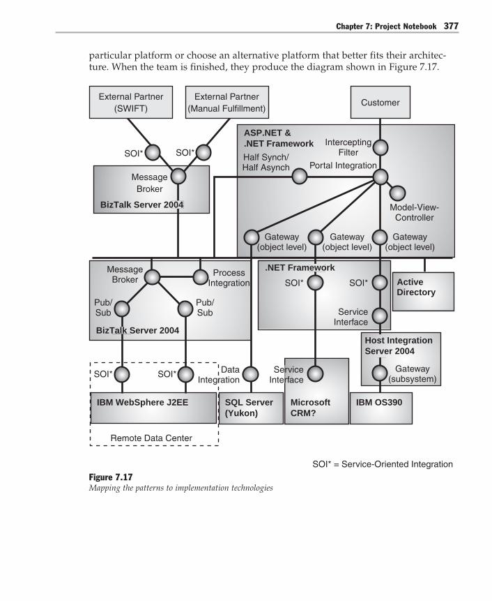
Chapter 7: Project Notebook 377
particular platform or choose an alternative platform that better fits their architec-ture. When the team is finished, they produce the diagram shown in Figure 7.17.
Customer
Model-View-Controller
SOI*
ServiceInterface
Gateway(subsystem)SOI*
SOI* = Service-Oriented Integration
Half Synch/ Half Asynch
Gateway(object level)
Gateway(object level)
Gateway(object level)
SOI*
SOI*
InterceptingFilter
Portal Integration
ASP.NET &.NET Framework
IBM OS390MicrosoftCRM?
SQL Server(Yukon)
Pub/Sub
MessageBroker
ProcessIntegration
Pub/Sub
Remote Data Center
BizTalk Server 2004
External Partner(SWIFT)
SOI*
External Partner(Manual Fulfillment)
SOI*
MessageBroker
BizTalk Server 2004
ServiceInterface
Host IntegrationServer 2004
.NET Framework
DataIntegration
IBM WebSphere J2EE
Active Directory
Figure 7.17Mapping the patterns to implementation technologies
Integration Patterns378
Figure 7.17 shows Global Bank’s integration architecture to be composed of numer-ous pattern-based design elements implemented on the Microsoft platform. To tracethe implementation of these elements down to running bits, refer to the appropriateimplementation pattern in previous chapters. For example, to understand how toimplement the gateway to the mainframe, refer to Implementing Gateway with HostIntegration Server 2004 in Chapter 5, “Integration Topologies.” This pattern includesthe details of connecting Global Bank’s .NET Framework – based portal applicationwith their existing COBOL-based CICS transactions.
Going ForwardThe last few pages of this chapter focused on distinctions between pattern typesand instances that may not be important for many design conversations. In conver-sations that require a precise distinction, it is helpful to clarify how you are usingpatterns. In these cases, using a pattern type model to enumerate design optionsand a pattern instance model to articulate specific design elements can be a veryeffective communication tool. Even if you are not interested in types and instances,however, patterns are a useful vehicle for communication among different levels ofthe enterprise.
This communication aspect of patterns is the main message of this chapter. Theprogression of pattern models discussed here will become increasingly important inthe future as developers, architects, and business leaders increasingly use patterns tobuild technology that meets business requirements.

Appendix
List of Patterns and PattletsThis appendix contains a table that lists patterns and pattlets that are referenced inthis book. Pattlets are actual patterns that this book refers to; however, the book doesnot discuss them in detail. The table also provides a reference to the original workthat identified the pattern or pattlet, if applicable.
Table A.1: List of Patterns and Pattlets
Pattern or pattlet Problem Solution Source
Entity Aggregation How can enterprise Introduce an Entitydata that is redundantly Aggregation layerdistributed across that provides amultiple repositories logical representationbe effectively of the entities at anmaintained by enterprise level withapplications? physical connections
that support theaccess and that updateto their respectiveinstances in back-endrepositories.
Process Integration How do you coordinate Define a businessthe execution of a process model thatlong-running business describes the individualfunction that spans steps that makemultiple disparate up the complex businessapplications? function. Create a
separate processmanager componentthat can interpretmultiple concurrentinstances of this modeland that can interactwith the existingapplications to performthe individual stepsof the process.
(continued)

Appendix380
Pattern or pattlet Problem Solution Source
Portal Integration How can users efficiently Create a portalperform tasks that require application that displaysaccess to information that the information thatresides in multiple is retrieved fromdisparate systems? multiple applications
in a unified userinterface. The user canthen perform therequired tasks basedon the information thatappears in this portal.
Data Integration How do you integrate Integrate applications atinformation systems that the logical data layer.were not designed to Use a Shared Database,work together? a File Transfer, or
a Maintain Data Copiesimplementation.
Shared Database How can multiple Have multiple applications Shared Database(a kind of data applications work store their data in a pattern [Hohpe04].integration) together to exchange single database. Define
information? a schema that handlesthe needs of all therelevant applications.
Maintain Data How can multiple Have multiple applications Maintain DataCopies applications work access multiple copies of Copies is the root(a kind of data together to exchange the same data. Maintain pattern for twelveintegration) information? state integrity between patterns (the data
copies. movement cluster)that are presentedin “Data Patterns”[Teale03].
File Transfer How can multiple At regular intervals, File Transfer(a kind of data applications work make each application pattern [Hohpe04].integration) together to exchange produce files that contain
information? the information that theother applications mustconsume. After a file iscreated, do not maintainthe file.
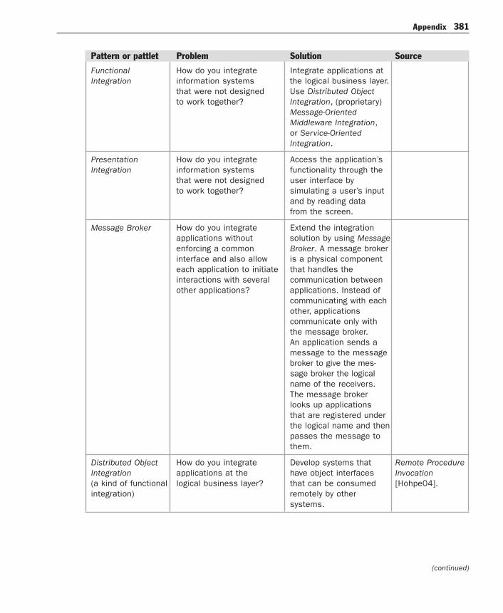
Appendix 381
Pattern or pattlet Problem Solution Source
Functional How do you integrate Integrate applications atIntegration information systems the logical business layer.
that were not designed Use Distributed Objectto work together? Integration, (proprietary)
Message-OrientedMiddleware Integration,or Service-OrientedIntegration.
Presentation How do you integrate Access the application’sIntegration information systems functionality through the
that were not designed user interface byto work together? simulating a user’s input
and by reading datafrom the screen.
Message Broker How do you integrate Extend the integrationapplications without solution by using Messageenforcing a common Broker. A message brokerinterface and also allow is a physical componenteach application to initiate that handles theinteractions with several communication betweenother applications? applications. Instead of
communicating with eachother, applicationscommunicate only withthe message broker.An application sends amessage to the messagebroker to give the mes-sage broker the logicalname of the receivers.The message brokerlooks up applicationsthat are registered underthe logical name and thenpasses the message tothem.
Distributed Object How do you integrate Develop systems that Remote ProcedureIntegration applications at the have object interfaces Invocation(a kind of functional logical business layer? that can be consumed [Hohpe04].integration) remotely by other
systems.
(continued)

Appendix382
Pattern or pattlet Problem Solution Source
Message-Oriented How do you integrate Use proprietary MessagingMiddleware applications at the message-oriented [Hohpe04].Integration logical business layer? middleware to send(a kind of functional messages asynchronously.integration)
Service-Oriented How do you integrate Use Web services toIntegration applications at the expose interfaces that(a kind of functional logical business layer? can be consumed remotelyintegration) by other systems.
Point-to-Point How do you ensure that Use Point-to-Point When you useConnection exactly one receiver Connection to integrate point-to-point
receives a message? two systems. The connections, eachsending system must system determinestranslate the message the address of allinto a format that the the other nodesreceiving system that it communi-understands. cates with.
Broker How can you structure Introduce a broker [Buschmann96].a distributed system whose tasks are toso that application locate services, todevelopers do not have forward requests, andto concern themselves to return responses towith the details of remote clients. Services registercommunication? themselves with the
broker. Clients accessservices by making aservice request throughthe broker.
Direct Broker How do you integrate Extend the integrationapplications without solution by using a directenforcing a common broker component thatinterface, allow each handles the communicationapplication to initiate between applications.interactions with several Initially, the applicationother applications, and asks the broker to locatereduce hot spots the other registered(performance problems applications based onthat occur under high the logical names of thoseloads in specific areas)? applications. From this
point forward, allcommunication is madedirectly betweenapplications.

Appendix 383
Pattern or pattlet Problem Solution Source
Indirect Broker How do you integrate Extend the integrationapplications without solution by using anenforcing a common indirect broker compo-interface, but allow each nent that handles theapplication to initiate communication betweeninteractions with several applications. Instead ofothers? communicating directly,
applications communi-cate only with the mes-sage broker. An applica-tion sends a message tothe broker. This messageprovides the logical nameof the receivers. Thebroker then looks upapplications that areregistered under thelogical name and passesthe message to thatapplication.
Publish/Subscribe How can an application Extend the communica-in an integration tion infrastructure by cre-architecture only send ating topics or by dynami-messages to the cally inspecting messageapplications that are content. Enable listeninginterested in receiving applications to subscribethe messages without to specific messages.knowing the identities Create a mechanism thatof the receivers? sends messages to all
interested subscribers.There are three variationsof the Publish/Subscribepattern that you can useto create a mechanismthat sends messages toall interested subscribers.The three variations areList-Based Publish/Subscribe, Broadcast-Based Publish/Subscribe, andContent-BasedPublish/Subscribe.
(continued)

Appendix384
Pattern or pattlet Problem Solution Source
Message Bus As an integration solution Connect all applicationsgrows, how can you through a logical componentlower the cost of known as a message bus.adding or removing A message bus specializesapplications? in transporting messages
between applications.A message bus containsthree key elements: a setof agreed-upon messageschemas; a set of commoncommand messages[Hohpe04], and a sharedinfrastructure for sendingbus messages to recipients.
Pipes and Filters How do you implement a Implement the transforma-sequence of transforma- tions by using a sequencetions so that you can of filter components, wherecombine and reuse them each filter component re-independently? ceives an input message,
applies a simple transforma-tion, and sends the trans-formed message to the nextcomponent. Conduct themessages through pipes[McIlroy64] that connect filteroutputs and inputs, and thatbuffer the communicationbetween the filters.
Gateway How can you make the Add a Gateway componentapplications of an that abstracts the accessintegration solution access to the external resource.an external system without The gateway presents aintroducing many-to-one single interface to thecoupling between the integrated applicationsapplications and while hiding the externalthe external system? resource interface. In
addition, the gatewayencapsulates any protocoltranslation that may benecessary to communicatewith the external resource.

Bibliography[Alexander79] Alexander, Christopher. The Timeless Way of Building. OxfordUniversity Press, 1979.
[Alur01] Alur, Deepak; John Crupi, and Dan Malks. Core J2EE Patterns: Best Practicesand Design Strategies. Prentice Hall, 2001.
[Baldoni03] Baldoni, R.; M. Contenti, and A. Virgillito. “The Evolution of Publish/Subscribe Communication Systems.” Future Directions of Distributed Computing.Springer Verlag LNCS Vol. 2584, 2003.
[Bertrand00] Meyer, Bertrand. Object-Oriented Software Construction. 2nd ed. Prentice-Hall, 2000.
[Box04] Box, Don. “Code Name Indigo: A Guide to Developing and RunningConnected Systems with Indigo.” MSDN Magazine. January 2004. Available fromthe MSDN Windows Code-Named “Longhorn” Developer’s Center at: http://msdn.microsoft.com/longhorn/understanding/pillars/indigo/default.aspx?pull=/msdnmag/issues/04/01/Indigo/default.aspx.
[Britton01] Britton, Chris. IT Architectures and Middleware — Strategies for BuildingLarge, Integrated Systems. Addison-Wesley, 2001.
[Buschmann96] Buschmann, Frank; Regine Meunier, Hans Rohnert, PeterSommerlad, and Michael Stal. Pattern-Oriented Software Architecture, Volume 1: ASystem of Patterns. John Wiley & Sons Ltd, 1996.
[Chandra03] Chandra, David; Anna Liu, Ulrich Roxburgh, Andrew Mason, E. G.Nadhan, Paul Slater. Guidelines for Application Integration, Microsoft Patterns &Practices, December 2003. Available on MSDN at: http://msdn.microsoft.com/library/default.asp?url=/library/en-us/dnpag/html/eappint.asp.
[Chapell03] David Chappell, Chappell & Associates. “Understanding BizTalk Server2004.” Microsoft Corporation, 2003. Available at http://go.microsoft.com/fwlink/?LinkId=21313.
[Crocker02] Crocker, Angela; Andy Olsen, and Edward Jezierski. “Designing DataTier Components and Passing Data Through Tiers.” MSDN Library, August 2002.Available at: http://msdn.microsoft.com/library/default.asp?url=/library/en-us/dnbda/html/boagag.asp.
[Erikkson00] Eriksson, Hans-Erik, and Magnus Penker. Business Modeling with UML:Business Patterns at Work. John Wiley & Sons, Inc., 2000.
[Firesmith95] Firesmith, Donald G., and Edward M. Eykholt. Dictionary of ObjectTechnology. Signature Sounds Recording, 1995.
[Fowler01] Fowler, Martin. “To Be Explicit.” IEEE Software, November/December2001.
Bibliography386
[Fowler03] Fowler, Martin. Patterns of Enterprise Application Architecture. Addison-Wesley, 2003.
[Gamma95] Gamma, Erich; Richard Helm, Ralph Johnson, and John Vlissides.Design Patterns: Elements of Reusable Object-Oriented Software. Addison-Wesley, 1995.
[Garlan95] Garlan, David; Robert Allen, and John Ockerbloom. “ArchitecturalMismatch: Why Reuse Is So Hard,” in IEEE Software, Volume 12, Issue 6, November1995: 17-26.
[Hohpe04] Hohpe, Gregor, and Bobby Woolf. Enterprise Integration Patterns: Design-ing, Building, and Deploying Messaging Solutions. Addison-Wesley, 2004.
[Januszewski01] Januszewski, Karsten. “Using UDDI at Run Time, Part I.” Decem-ber, 2001. Available on MSDN at http://msdn.microsoft.com/library/default.asp?url=/library/en-us/dnuddi/html/runtimeuddi1.asp.
[Januszewski02] Januszewski, Karsten. “Using UDDI at Run Time, Part II.” May,2002. Available on MSDN at http://msdn.microsoft.com/library/default.asp?url=/library/en-us/dnuddi/html/runtimeuddi2.asp.
[Kent00] Kent, William. Data and Reality. 1stBooks Library, 2000.
[Larman02] Larman, Craig. Applying UML and Patterns. Prentice-Hall PTR, 2002.
[Levine03] Levine, Russell. “The Myth of the Disappearing Interfaces,” in BusinessIntegration Journal, November 2003.
[Linthicum04] Linthicum, David. Next Generation Application Integration. Addison-Wesley, 2004.
[Mackinnon00] Mackinnon, Tim, et al. “Endo-Testing: Unit Testing with MockObjects.” eXtreme Programming and Flexible Processes in Software Engineering —XP2000 conference.
[Manolescu97] Manolescu, Dragos. “A Data Flow Pattern Language,” in Proceedingsof the 4th Pattern Languages of Programming, September 1997, Monticello, Illinois.
[Marcus00] Marcus, Evan, and Hal Stern. Blueprints for High Availability: DesigningResilient Distributed Systems. John Wiley & Sons, 2000.
[Martin02] Martin, Robert. Agile Software Development: Principles, Patterns, andPractices. Prentice-Hall, 2002.
[McIlroy64] The fluid-flow analogy dates from the days of the first UNIX systemsand is attributed to Douglas McIlroy; see http://cm.bell-labs.com/cm/cs/who/dmr/mdmpipe.html.
[Microsoft02-1] Microsoft Corporation. “XML Web Services Overview.” .NET Frame-work Developer’s Guide. Available on MSDN at: http://msdn.microsoft.com/library/default.asp?url=/library/en-us/cpguide/html/cpconwebservicesoverview.asp.

Bibliography 387
[Microsoft02-2] Microsoft Corporation. “Application Architecture: ConceptualView.” .NET Architecture Center. Available on MSDN at: http://msdn.microsoft.com/architecture/default.aspx?pull=/library/en-us/dnea/html/eaappconland.asp.
[Microsoft02-3] Microsoft Press. Microsoft Computer Dictionary, Fifth Edition.Microsoft Press, 2002.
[Microsoft04] Microsoft Corporation. “Certificate Stores.” Windows XP ProfessionalProduct Documentation. Available from Microsoft.com at http://www.microsoft.com/resources/documentation/windows/xp/all/proddocs/en-us/sag_cmuncertstor.mspx.
[Mowbray97] Mowbray, Thomas J. Corba Design Patterns. John Wiley & Sons, 1997.
[Newcomer02]. Newcomer, Eric. Understanding Web Services: XML, WSDL, SOAP, andUDDI. Addison-Wesley, 2002.
[Noble98] Noble, J. “Classifying Relationships Between Object-Oriented DesignPatterns.” Proceedings of the Australian Software Engineering Conference (ASWEC),1998.
[Oki93] Oki, B.; M. Pfluegel, A. Siegel, and D. Skeen. “The Information Bus - AnArchitecture for Extensive Distributed Systems.” Proceedings of the 1993 ACM Sympo-sium on Operating Systems Principles, December 1993.
[PnP02] Patterns & Practices, Microsoft Corporation. “Application Architecturefor .NET: Designing Applications and Services.” MSDN Library, December 2002.Available at: http://msdn.microsoft.com/library/default.asp?url=/library/en-us/dnbda/html/distapp.asp.
[Reilly02] Reilly, Douglas J. Designing Microsoft ASP.NET Applications. MicrosoftPress, 2002.
[Ruh01] Ruh, William. Enterprise Application Integration. A Wiley Tech Brief. Wiley,2001.
[Schmidt00] Schmidt, Douglas; Michael Stal, Hans Rohnert, Frank Buschmann.Pattern-Oriented Software Architecture, Volume 2: Patterns for Concurrent and NetworkedObjects. John Wiley & Sons, 2000.
[Shaw96] Shaw, Mary, and David Garlan, Software Architecture: Perspectives on anEmerging Discipline. Prentice Hall, 1996.
[Skonnard03] Skonnard, Aaron. “How ASP.NET Web Services Work.” MSDN Library,May 2003. Available at: http://msdn.microsoft.com/library/default.asp?url=/library/en-us/dnwebsrv/html/howwebmeth.asp.
[Skonnard03-2] Skonnard, Aaron. “Understanding SOAP.” MSDN Web ServicesDeveloper Center, March 2003. Available at: http://msdn.microsoft.com/webservices/understanding/webservicebasics/default.aspx?pull=/library/en-us//dnsoap/html/understandsoap.asp.

Bibliography388
[Slywotsky99] Slywotsky, Adrian J. Profit Patterns: 30 Ways to Anticipate and Profitfrom Strategic Forces Reshaping your Business. John Wiley & Son Ltd, 1999.
[Tannebaum01] Tannebaum, Andrew. Modern Operating Systems. 2nd ed. Prentice-Hall, 2001.
[Teale03] Teale, Philip, Christopher Etz, Michael Kiel, and Carsten Zeitz. “DataPatterns.” .NET Architecture Center. June 2003. Available at: http://msdn.microsoft.com/architecture/patterns/default.aspx.
[Trowbridge03] Trowbridge, David; Dave Mancini, Dave Quick, Gregor Hohpe,James Newkirk, and David Lavigne. Enterprise Solution Patterns Using Microsoft.NET. Microsoft Press, 2003. Also available on the MSDN Architecture Center at: http://msdn.microsoft.com/architecture/patterns/default.aspx?pull=/library/en-us/dnpatterns/html/Esp.asp.
[W3C04] “Web Services Architecture W3C Working Draft 11 February 2004.” Avail-able on the W3C Web site at: http://www.w3.org/TR/2004/NOTE-ws-arch-20040211/.
[Wanagel03] Wanagel, Jonathan, et al. “Building Interoperable Web Services: WS-IBasic Profile 1.0.” MSDN Library, August 2003. Available at: http://msdn.microsoft.com/library/default.asp?url=/library/en-us/dnsvcinter/html/wsi-bp_msdn_landingpage.asp.
[Yacoub04] Yacoub, M. Shreif and Hany H. Ammar. Pattern-Oriented Analysis andDesign: Composing Patterns to Design Software Systems. Addison-Wesley, 2004.

A3270 terminal standard, 208<types> element, 177ABA routing numbers, 35abstraction level, 56account services
accessing on the mainframe, 44–46
tradeoffs, 46ACID
Data Integration pattern, 130Process Integration pattern, 81
ACORD XML, 290–292Activator.GetObject() method call,
219Active Directory directory service,
46–50Adapter pattern, 142, 222adapters
Message Broker pattern, 247–248SQL Server, 90
American Bankers Association SeeABA
Application vs. Integration patterns,48, 213
applicationsadapters, 247–249communication with Message
Bus pattern, 262dependencies, 260monitoring with BizTalk Server
2004, 306redefining concept of, 3
architectureapproaches to Entity Aggregation
pattern, 66–67enterprise architecture stack,
355–356integration architecture views,
365–378
technical architecture, 51, 367–369
See also baseline architectureartifacts
interpreting, 342purpose of, 341
ASCII, 283ASP.NET See Service-Oriented
Integration pattern withASP.NET
Assembly Key File name property,101
associative tables, 224asynchronous interaction
with callback, 189–190with polling, 189–190
asynchronous Web services, 188–190
atomic transactions, 81Atomicity, Consistency, Isolation,
and Durability See ACIDaudience for this book, xi–xiiauthoritative source, 71authors, xvi
contributors, xvautomation level, 55–56
BB2B integration, 310–311BAM, 60banking services bundle, 351–354baseline architecture
basic purpose of, 33mapping to technologies, 52–53SWIFT gateway, 35–43using patterns to design, 19–53See also architecture
bibliography, 385–388integration patterns and their
relationships, 389
binding files, 101BizTalk Server 2004, 86–105
background, 86benefits and liabilities, 103–104and Broker pattern, 221context, 86correlating messages and
process instances, 88diagram, 87Execute Scheduled Payments
orchestration, 90–103example, 91–103
handling exceptions andcompensating transactions,89–90
implementation strategy, 86–90Indirect Broker pattern, 221Message Broker pattern, 221, 243,
245–259operational considerations, 105orchestration, 86–88Orchestration Designer, 87with port-level tracking
monitoring, 306–307process managers, 104process modeling, 86–88Publish/Subscribe pattern
example, 280related patterns, 105Scope shape, 89security considerations, 104–105Send shape, 88and subscriptions, 253–255, 280testing considerations, 104See also Message Broker pattern;
Pipes and Filters pattern;Service-Oriented Integrationpattern with BizTalk Server2004
Index

Index390
Blackboard pattern, 271books, 48BPEL, 82BPML, 82Broadcast-Based Publish/Subscribe
pattern, 223–224, 232List-Based Publish/Subscribe
pattern, 274Message Bus pattern, 263, 265Publish/Subscribe pattern, 274security considerations, 281
Broker pattern, 215–221, 231communication responsibilities
of, 215–216diagram of related patterns, 216Distributed Object Integration
pattern, 215and Ethernet, 231examples, 218–221
BizTalk Server 2004, 221CORBA, 220DCOM, 219.NET Framework remoting,
219–220UDDI, 220
intent of brokers, 215logical topology, 231physical topology, 231Service-Oriented Integration
pattern, 215UDP, 220, 231vs. Point-to-Point Connection
pattern, 221bus arbitration, 266bus contention, 266bus latency, 266Business Activity Monitoring See
BAMbusiness logic, 132Business Process Execution
Language See BPELBusiness Process Modeling
Language See BPMLBusiness Rule Engine, 257–258
Ccanonical schema, 68capital expenditure, 345Catch SOAP Exception, 96CEO
scenario context, 4viewpoints, 346–351
certificate thumbprints, 299change management, 71–72CheckBalanceAndDebit, 95–96chief executive officer See CEOchief technical officer See CTOchurn, 346, 348CICS
acronym defined, 5business logic, 332compatability with .NET
Framework, 319mainframe connections, 25transactions, 322–327
choices, 322class-responsibility-collaboration
See CRCClient-Dispatcher-Server pattern, 243client-side asynchrony, 188, 190COBOL Import Wizard, 328COMMAREA, 323, 325, 332commercial off-the-shelf software
See COTSCommon Object Request Broker
Architecture See CORBAcommunication in Broker pattern,
215–216community, xiv–xvcompensation in Entity Aggregation
pattern, 70–71composite applications, 78configuration in Entity Aggregation
pattern, 71Content-Based Publish/Subscribe
pattern, 223–225, 234–235Message Bus pattern, 263–265Publish/Subscribe pattern, 275routing, 264, 275
Content-Based Router pattern, 243,258
content-based systems, 224–225,275–276
context properties, 248contributors, xvconventions, xiv, 20convergence, 342Convergence pattern, 343CORBA
acronym defined, 38Broker pattern, 220Direct Broker pattern, 231Service-Oriented Integration
pattern, 147correlation set, 88COTS, 11coupling, 57
Gateway pattern, 314Message Broker pattern, 240Pipes and Filters pattern, 292Service-Oriented Integration
pattern, 146–147CRC, 14CreditAccount web method, 100CRM
Gateway object, 49–50in Global Bank scenario, 5overview of system connections,
24–25cross-pane interactivity, 108CTO
decision points, 345scenario context, 4–5, 11scenario requirements, 21
Cunningham, Ward, 19custom pipelines, 298–299customer churn, 346, 348customer information, 69Customer Information Control
System See CICSCustomer Relationship
Management See CRM
DData and Reality, 57Data Consistency Integration pattern,
134
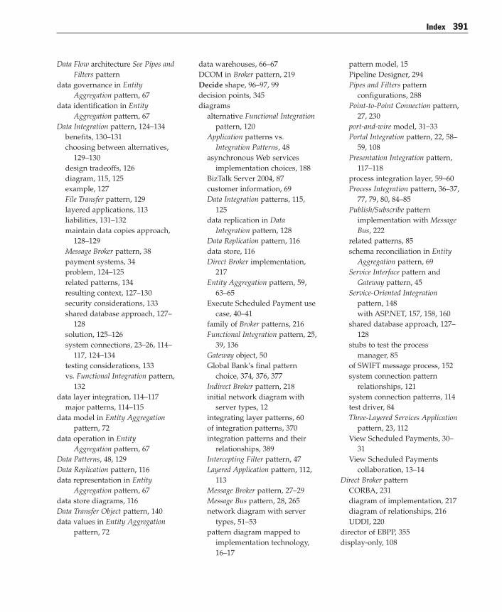
Index 391
Data Flow architecture See Pipes andFilters pattern
data governance in EntityAggregation pattern, 67
data identification in EntityAggregation pattern, 67
Data Integration pattern, 124–134benefits, 130–131choosing between alternatives,
129–130design tradeoffs, 126diagram, 115, 125example, 127File Transfer pattern, 129layered applications, 113liabilities, 131–132maintain data copies approach,
128–129Message Broker pattern, 38payment systems, 34problem, 124–125related patterns, 134resulting context, 127–130security considerations, 133shared database approach, 127–
128solution, 125–126system connections, 23–26, 114–
117, 124–134testing considerations, 133vs. Functional Integration pattern,
132data layer integration, 114–117
major patterns, 114–115data model in Entity Aggregation
pattern, 72data operation in Entity
Aggregation pattern, 67Data Patterns, 48, 129Data Replication pattern, 116data representation in Entity
Aggregation pattern, 67data store diagrams, 116Data Transfer Object pattern, 140data values in Entity Aggregation
pattern, 72
data warehouses, 66–67DCOM in Broker pattern, 219Decide shape, 96–97, 99decision points, 345diagrams
alternative Functional Integrationpattern, 120
Application patterns vs.Integration Patterns, 48
asynchronous Web servicesimplementation choices, 188
BizTalk Server 2004, 87customer information, 69Data Integration patterns, 115,
125data replication in Data
Integration pattern, 128Data Replication pattern, 116data store, 116Direct Broker implementation,
217Entity Aggregation pattern, 59,
63–65Execute Scheduled Payment use
case, 40–41family of Broker patterns, 216Functional Integration pattern, 25,
39, 136Gateway object, 50Global Bank’s final pattern
choice, 374, 376, 377Indirect Broker pattern, 218initial network diagram with
server types, 12integrating layer patterns, 60of integration patterns, 370integration patterns and their
relationships, 389Intercepting Filter pattern, 47Layered Application pattern, 112,
113Message Broker pattern, 27–29Message Bus pattern, 28, 265network diagram with server
types, 51–53pattern diagram mapped to
implementation technology,16–17
pattern model, 15Pipeline Designer, 294Pipes and Filters pattern
configurations, 288Point-to-Point Connection pattern,
27, 230port-and-wire model, 31–33Portal Integration pattern, 22, 58–
59, 108Presentation Integration pattern,
117–118process integration layer, 59–60Process Integration pattern, 36–37,
77, 79, 80, 84–85Publish/Subscribe pattern
implementation with MessageBus, 222
related patterns, 85schema reconciliation in Entity
Aggregation pattern, 69Service Interface pattern and
Gateway pattern, 45Service-Oriented Integration
pattern, 148with ASP.NET, 157, 158, 160
shared database approach, 127–128
stubs to test the processmanager, 85
of SWIFT message process, 152system connection pattern
relationships, 121system connection patterns, 114test driver, 84Three-Layered Services Application
pattern, 23, 112View Scheduled Payments, 30–
31View Scheduled Payments
collaboration, 13–14Direct Broker pattern
CORBA, 231diagram of implementation, 217diagram of relationships, 216UDDI, 220
director of EBPP, 355display-only, 108

Index392
Distributed Common Object ModelSee DCOM
Distributed Object Integrationpattern
Broker pattern, 215CORBA, 220DCOM, 219Functional Integration pattern,
119–120, 138, 140, 143Global Bank alternative, 372programming models, 141, 143vs. Service-Oriented Integration
pattern, 159DMZ, 44document/literal SOAP styles,
149–150documentation conventions, xivdomain knowledge, 34duplicate messages, 141dynamic configuration, 257dynamic subscriptions See
subscriptions
EEBCDIC, 283EBPP, 354–355EBPP Supervisor, 355, 363Einstein, Albert, 1, 11Electronic Bill Presentment and
Payment See EBPPencapsulation, 24–25, 132, 143endpoint registration, 216Enterprise Application Architecture,
49enterprise architecture stack,
355–356Enterprise Information Integration,
75enterprise integration, 310Enterprise Integration Patterns:
Designing, Building, andDeploying Messaging Solutions,221
Enterprise Integration Patterns, 128,191
Enterprise Resource Planing SeeERP
Enterprise Solution Patterns UsingMicrosoft .NET, xi, xvi, 6, 44,215
class-level Gateways, 49other patterns in, 48
Entity Aggregation pattern, 59, 61–75
architectural approaches, 66–67benefits and liabilities of, 73change management, 71–72compensating, 70–71configuration, 71context, 61–62data governance, 67data identification, 67data model, 72data operation, 67data representation, 67data values, 72design considerations, 67diagrams, 63–65entities, 61entity representation, 67–68inquiring vs. updating, 70integration layer types, 59known uses, 75operational considerations, 74ownership, 71Phone Number entity example,
64–66Portal Integration pattern, 62process, 63–66references, 70related patterns, 75schema reconciliation, 67–69schema reconciliation diagram,
69security considerations, 74solution, 62–66testing considerations, 74
entity references in EntityAggregation pattern, 70
entity representation in EntityAggregation pattern, 67–68
ERP, 104–105, 127error handling, 92
Ethernet, 226–229Broker pattern, 231
Execute Scheduled Payment usecase, 33–35
baseline architecture, 33models, 40–43Pipes and Filters pattern with
BizTalk Server 2004, 296–297Execute Scheduled Payments
orchestration, 90–103example, 91–103process model, 92SQL Server adapter, 90, 101–103
experience, 11external gateway for B2B
integration, 310–311
Ffar links, 26fault tolerance, 257feedback and support, xvFile Transfer pattern, 114–117
Data Integration pattern, 129logical data layer, 126
filter reuse, 305filters See Pipes and Filters patternfinancial planning services team,
351fixed subscriptions See
subscriptionsFollowing Correlation Set, 88Fowler, Martin, 44, 49, 128Functional Integration pattern, 24–26
accessing account services onthe mainframe, 44
Data Integration pattern, 132Data Transfer Object pattern, 140diagram, 39diagram of alternatives, 120Distributed Object Integration
pattern, 119–120for functionality sharing, 38layered applications, 113Message Broker pattern, 38Message-Oriented Middleware
Integration pattern, 119–120,140–141

Index 393
privacy and encryption issues,133
Process Integration pattern, 79programming models, 143, 144relation to Data Integration
pattern, 134Remote Facade pattern, 140requirements, 137Service-Oriented Integration
pattern, 119–120, 138–139,141–142
system connections, 118–120,135–145benefits, 142–143choosing between
alternatives, 139–140choosing Distributed Objects,
140credit scoring example, 119diagram, 136Distributed Object Integration
pattern, 138, 140forces, 135–136integrating external
applications, 137kinds of functional
integration, 119–120liabilities, 143–144Message-Oriented Middleware
Integration pattern, 138, 140problem, 135resulting context, 138security considerations, 144Service-Oriented Integration
pattern, 139, 141–142solution, 136–137table, 137testing considerations, 144
functionality sharing, 38
Ggateway chaining, 311–312Gateway object
CRM, 49–50diagram, 50
Gateway pattern, 33–35, 308–318account system testing, 46benefits, 314–315context, 308described, 44–45example, 312–314gateway choices, 310–311with Host Integration Server
2004, 319–339background, 319–320benefits, 339components, 331context, 319example, 331functions, 332
selecting the programmingmodel, 332
configuring the mainframeenvironment, 332
configuring the TImetadata file, 333–337
configuring networkprotocol connectivity,337
configuring a TI remoteenvironment, 338
adding an IIS virtualdirectory, 338
configuring a Windows-initiated processingobject, 338
implementing a .NETFramework clientapplication, 339
Global Bank property valuestable, 338
implementation strategy, 320–331 selecting the programming
model, 322–326 configuring the mainframe
environment, 326–327 configuring the TI
Metadata File, 327–328 configuring network
protocol connectivity,328–329
configuring a remoteenvironment, 330
adding an IIS virtualdirectory, 330
configuring a Windows-initiated processingobject, 331
implementing a .NETFramework clientapplication, 331
liabilities, 339processing object property
values, 338tests, 339
liabilities, 315operational considerations, 317overview, 44–45, 284–285problem, 308related patterns, 317responsibilities and
collaborations, 310security considerations, 316Service Interface pattern, 44–45solution, 309–312testing considerations, 315–316
General Manager of banking SeeGM of banking
Global Bank scenarioasynchronous business practice,
151–152baseline architecture role design,
21–50account services on the
mainframe, 44–46Execute Scheduled Payment
and Receive PaymentResponse, 35–43
implementing the GlobalBank scenario, 50–53
message broker for the loansystems, 29–33
portal Web application, 46–50scheduled payment use case,
33–35View Scheduled Payments
use case, 21–33

Index394
Global Bank scenario (continued)context, 4, 342–343described, 4–6enterprise architecture stack,
355–358Execute Scheduled Payments
orchestration, 90–103example, 91–103
final pattern choice, 374, 376, 377method parameters, 336network diagram with server
types, 51–53next steps, 6pattern instances, 376patterns, 11–17patterns to communicate design
decisions, 20requirements, 4–5, 19–21See also project notebook; View
Scheduled Payments use caseGM of banking, 351–354, 359GotDotNet community, xiv–xvgranularity, 126
HHalf Synch/Half Asynch pattern, 49–
50HAT tool, 203, 204, 255, 307health, 273HLLAPI, 208host-initiated processing, 320how this book is organized, xii–xiiiHruby, Pavel, 358hub-and-spoke architecture, 218, 237
See also Message Broker pattern
Iidempotent messages, 141IDL, 147IIS, 161, 321
virtual directory, 330Implementing Broker with .NET
Remoting Using Client-Activated Objects, 220
Implementing Broker with .NETRemoting Using Server-Activated Objects, 220
Implementing Gateway with HostIntegration Server 2004 pattern,317
Implementing Pipes and Filters withBizTalk Server 2004 pattern,295
Implementing Process Integrationwith BizTalk Server 2004pattern, 85
Implementing Service-OrientedIntegration with ASP.NETpattern, 155
Implementing Service-OrientedIntegration with BizTalk Server2004, 155, 179, 243
IMS transactions, 322In-band and Out-of-band Partitions
pattern, 295Indirect Broker pattern
and BizTalk Server 2004, 221diagram of relationships, 216implementation diagram, 218similarity to Mediator pattern,
217initial network diagram with
server types, 12initial subscriptions See
subscriptionsInitializing Correlation Set, 88inquiring vs. updating in Entity
Aggregation pattern, 70instance-based collaboration, 119instance-based integration, 159instances, 375–378integrating layer, 55–110
choosing an integration layertype, 57–60
coupling, 57integrating layer patterns, 60level of abstraction, 56level of automation, 55–56maintaining state, 56–57semantic dissonance, 57types, 370–371See also BizTalk Server 2004;
Entity Aggregation pattern;Portal Integration pattern;Process Integration pattern
integrationapplications, 3patterns, 1–17problem of, 1–3
integration layer types, 57–60Entity Aggregation pattern, 59Portal Integration pattern, 58–59process integration layer, 59–60
integration layers patterns table,285
Integration patterns, 369–378types of patterns, 371vs. Application patterns, 48, 213
integration topologies, 26–28, 213–282
Broker pattern, 215–221, 231examples, 218–221
integration topology level, 229logical topology, 226–230Message Broker implementation
with BizTalk Server 2004, 245–259
Message Broker pattern, 237–244Message Bus and Publish/
Subscribe patterns, 231–235Message Bus pattern, 221–223,
260–271physical topology, 226Point-to-Point Connection pattern,
214–215, 229–230Publish/Subscribe pattern, 223–
225, 272–282subscription mechanisms, 277table of integration patterns, 236topology levels, 225–229using topologies together, 229–
235See also Broker pattern; Message
Broker pattern; Message Buspattern; Publish/Subscribepattern
integration topology, 226Intercepting Filter pattern, 295
diagram, 47further information on, 48, 295portal Web application, 46–50

Index 395
internal gateway for enterpriseintegration, 310
interprocess communicationmechanisms, 317
JJanuszewski, Karsten, 220
KKent, William, 57
Llanguages for defining process
models, 82latency tolerance, 126Layered Application pattern
Presentation Integration pattern,206
system connections, 111–112layers
Process Integration pattern, 36–37Three-Layered Services Application
pattern, 23See also integrating layer
link-to-program name, 328list of patterns and pattlets, 379–
384List-Based Publish/Subscribe pattern,
223, 232–233Broadcast-Based Publish/Subscribe
pattern, 274Message Bus pattern, 263, 265Publish/Subscribe pattern, 273–
274load-balancing, 257loan system
connection, 26Message Broker pattern, 29–33
logical data layer, 126logical services, 365–367logical topology
Broker pattern, 231CORBA, 220integration topologies, 226–230
loose coupling, 57
LU 6.2 protocol, 322–323alternatives, 326components, 324–325
Mmainframes
accessing account services onthe mainframe, 44–46
connection overview, 25Maintain Data Copies pattern, 114–
117considerations, 130Data Replication pattern, 116list of other patterns, 129logical data layer, 126
master references in EntityAggregation pattern, 70
master/subordinate relationships,126
Mediator pattern, 217, 243MEP, 150–151mergers and acquisitions, 342–343Message Broker pattern, 27–28, 237–
243benefits, 240–241and BizTalk Server 2004, 221,
243, 245–259adapter types, 247–248benefits, 255business rule engine, 257–258context, 245context and background, 245–
246diagram of internal publish-
subscribe architecture, 247example, 249–255
creating the receive portand defining messageschemas, 250–252
defining maps to convertbetween messageformats, 252–253
creating subscriptions tomessages, 253–255
implementation strategy, 246–249
liabilities, 255operational considerations,
257related patterns, 258–259security considerations, 256testing considerations, 256variants, 257
business rule engine, 257–258characteristics of, 218context, 237and coupling, 240Data Integration, 38diagram of relationships, 216example, 239–240Functional Integration pattern,
38–39known uses, 243liabilities, 241for loan system, 29–33loan system, 29–33operational considerations, 243for payment channels, 37–38problem, 237–238routing, 255security considerations, 239, 242Service-Oriented Integration
pattern, 38–39solution, 238–239subscriptions, 256, 258testing considerations, 242variants and related patterns,
243Message Bus pattern, 28, 221–223,
260–271application communication, 262benefits, 269with Broadcast-Based Publish/
Subscribe, 263with Content-Based Publish/
Subscribe, 263–264context, 260difficulties of, 237example, 266–268liabilities, 269–270with List-Based Publish/Subscribe,
263

Index396
Message Bus pattern (continued)Message Router, 262operational considerations, 270physical topology, 232–233with Publish/Subscribe, 222–225,
231–235, 262related patterns, 271responsibilities and
collaborations, 266routing, 234security considerations, 270solution, 261–266subscriptions, 264
message buses, 214message exchange patterns See
MEPMessage Router pattern, 262message switch, 264Message-Oriented Middleware
Integration pattern, 119–120,138, 143
Functional Integration pattern,119–120, 140–141
Global Bank alternatives, 372Messaging Gateway pattern, 317Microsoft books, 48models for Execute Scheduled
Payment use case, 40–43MSMQT, 248, 250
Nnear links, 26.NET Framework, 159–161
compatability with CICS, 319LU 6.2 protocol, 324–325
.NET Framework remoting, 219–220
network diagram with servertypes, 51–53
NUnit, 144, 178, 202, 204
Oobject request broker See ORBobject-oriented design and
abstraction, 56Observer pattern, 223, 273–274
Open Systems Interconnection SeeOSI
ORBBroker pattern, 220Service-Oriented Integration
pattern, 147See also CORBA
orchestrationBizTalk Server 2004, 86–88Execute Scheduled Payments, 90Orchestration Debugger, 204Orchestration Designer, 87
organization of this book, xii–xiiiOS/400 transactions, 322OSI stack, 225ownership in Entity Aggregation
pattern, 71
PParty Resolution component, 248pattern-based design, 10Pattern-Oriented Software
Architecture, Volume 1: ASystem of Patterns, 215
patternsapplying, 11communication aspect of, 378data layer integration, 114–115derived from Maintain Data
Copies pattern, 129diagrams
implementation technology,16
of integration patterns, 370Global Bank, 11–17, 374, 376, 377instances, 375–378instances in project notebook,
375–378model diagram, 15in music, 9other Microsoft guides, 48overview, 7–11pattern-based design, 10in sports, 7–8structure of, 9–10system interactions, 11–13table of system connection
patterns, 122–123
types, 371–375types and instances, 372
patterns and pattlets list, 379–384Patterns of Enterprise Application
Architecture, 44pattlets list, 379–384payment channels, 33–34payment system connection, 24perimeter network, 44Phone Number entity, 64–66physical topology, 214
Broker pattern, 231choices, 225integration topologies, 225–228Message Bus pattern, 232–233
Pipeline Designer, 294Pipes and Filters pattern
benefits, 292–293with BizTalk Server 2004, 296–
307background, 296–297benefits, 305custom pipelines, 298–299example, 299–304
creating a custom sendpipeline, 299
assigning and configuringthe filters, 299–301
building and deployingthe pipeline, 301
assigning certificates,301–303
configuring the send portto use the custompipeline, 304
implementation strategy, 297–299
liabilities, 305operational considerations,
306–307Pipeline Designer, 294receive pipeline, 298security considerations, 306send pipelines, 300testing considerations, 305–
306transformation components,
298

Index 397
context, 286diagram of different
configurations, 288example, 290–292forces, 286liabilities, 293overview, 283problem, 286related patterns, 295responsibilities and
collaborations, 290SLA, 293solution, 287–290testing considerations, 293–295
Point-to-Point Connection pattern,26–27
diagrams, 27, 230Global Bank alternatives, 372integration topologies, 229–230payment system, 34strengths and weaknesses, 214–
215vs. Broker pattern, 221
port management, 258port-and-wire model, 31–32, 40–43,
369port-level tracking, 306–307Portal Integration pattern, 58–59,
106–110and amibiguity, 57analogy to Entity Aggregation
pattern, 62benefits and liabilities, 109–110context, 106diagram, 22, 108example, 109flavors, 108integration layer types, 58–59and semantic dissonance, 57solution, 107–109table of solution components,
109vs. Process Integration pattern,
107, 110portal Web application
Global Bank, 46–50
Half Synch/Half Asynch pattern,49–50
Intercepting Filter pattern, 46–50predictive routing, 258preface, xi–xviPresentation Integration pattern,
24–26diagram, 117HLLAPI, 208Layered Application pattern, 206layered applications, 113system connections, 117–118,
206–212benefits, 210brittleness of, 208context, 206example, 209forces, 206–207liabilities, 210–211security considerations, 212solution, 207–209table of components, 209testing considerations, 211
privacy and security issues, 133Process Integration pattern, 76–85
ACID, 81benefits and liabilities, 83choosing, 59–60collaboration table, 79context, 76correlating messages and
process instances, 81diagrams, 36–37, 77, 80, 84–85Execute Scheduled Payment and
Receive Payment Response,35–43
Functional Integration pattern, 79handling exceptions and
compensating transaction, 82implementation details, 80–82integration layer types, 59–60pattern described, 36–37problem, 76–77process integration components
table, 79process managers, 79–80, 82–83,
85
process model, 107–108solution, 77–80straight-through processing, 82testing considerations, 84transaction, 81vs. Portal Integration pattern, 107,
110Process Manager pattern, 85, 105process managers
BizTalk Server 2004, 104pattern, 105Process Integration pattern, 79–80,
82–83, 85process model
BizTalk Server 2004, 86–88Execute Scheduled Payments
orchestration, 92Portal Integration pattern, 107–
108Process Integration pattern, 77–79
process value analysis, 365programming models
to access CICS transactions, 322–327
and BizTalk Server 2004, 103Distributed Object Integration
pattern, 141Functional Integration pattern,
143, 144and Gateway pattern, 49.NET Framework remoting, 219–
220TI, 321–323
project notebook, 341–378banking services bundle, 351–
354banking services team, 351bundling services, 350business architecture views,
358–364business context, 342–343from business scenario to
technical solution, 355–369current portfolio vs. industry
average, 346–348current services bundle vs.
industry average, 350–354

Index398
enterprise architecture stack,355–356
Global Bank business context,342–343
going forward, 378integration architecture views,
365–378architecturally significant use
cases, 369integration patterns, 369–371logical services, 365–367process value analysis, 365technical architecture, 367–369
integration patterns, 369–378interpreting the artifacts, 342pattern types, 371–375patterns instances, 375–378stakeholder viewpoints, 344–355
board of directors viewpoint,344
CEO viewpoint, 346–351director of EBPP, 354, 362–363EBPP supervisor, 355GM of banking, 351–354
strategy formulation, 348–350value proposition for online
services, 344–345viewpoints
of CEO, 358–359described, 357of GM, 360–361integration architecture, 365of process owner, 362–363of process worker, 363–364within the enterprise
architecture, 357–369See also Global Bank scenario
promoted properties, 248property schema, 248Pub/Sub See Publish/Subscribe
patternPublish-Subscribe Channel pattern,
282Publish/Subscribe pattern
applying, 275–278benefits, 280BizTalk Server 2004, 280
Broadcast-Based Publish/Subscribepattern, 274
Content-Based Publish/Subscribepattern, 275
context, 272dynamic subscriptions, 277–278example, 280fixed subscriptions, 277integration topologies, 272–282liabilities, 281List-Based Publish/Subscribe
pattern, 273–274Message Bus pattern, 222–225,
231–235, 262operational considerations, 281problem, 272–273refinements, 223related decisions, 279related patterns, 271, 282responsibilities and
collaborations, 279security considerations, 281solution, 273–279subscriptions, 225, 234, 275, 277–
278testing considerations, 281See also Broadcast-Based Publish/
Subscribe pattern; Content-Based Publish/Subscribepattern; List-Based Publish/Subscribe pattern
purpose of this book, 1–2push vs. pull, 126
QQoS, 238, 239, 241quality of service See QoS
RReceive Payee Response shape, 98Receive Payment Response use
case, 35–44receive pipeline, 298Receive shape, 92ReceiveDebitResponse shape, 95ReceivePaymentRequest
orchestration port, 92, 101
ReceivePaymentResponse, 98, 101receiver adapters, 248–249references in Entity Aggregation
pattern, 70remote environment, 321, 330Remote Facade pattern, 140Remote Method Invocation See
RMIRemote Procedure Call See RPCRemote Proxy pattern, 317replication approach, 66–67RMI, 38ROM, 4rough-order-of magnitude See
ROMrouting
Content-Based Publish/Subscribepattern, 264, 275
Content-Based Router pattern, 243described, 214–215Message Broker pattern, 255Message Bus pattern, 234SWIFT, 35
RPC, 149–150
SSaarinen, Eliel, 213sales, general, and administrative
See SGAscenarios See Global Bank scenarioschema reconciliation, 67–69Scope shape, 89, 96, 100screen scraping, 24, 113, 206, 207screened subnet, 44Sears, Richard, 341security and Message Broker
pattern, 239, 242security and privacy issues, 133semantic dissonance, 57, 132send pipelines, 300Send shape, 88SendDebitRequest shape, 95SendPaymentRequest, 98, 101server types network diagram,
51–53service, definition of, 120, 139, 148

Index 399
Service Gateway patternfurther information on, 48Service-Oriented Integration
pattern, 139Service Interface pattern
account system testing, 46further information on, 48Gateway pattern, 44–45, 317Global Bank portal application,
49–50related patterns, 317Service-Oriented Integration
pattern, 41, 139, 141–142Web services, 148
service level agreement See SLAservice stubs, 84–85Service-Oriented Integration pattern
acronym, 15alternate implementations, 53Broker pattern, 215Functional Integration pattern,
119–120, 138–139, 141–142functional integration with
Message Broker pattern, 38–39with Gateway pattern, 44Global Bank alternatives, 372system connections, 141–142,
146–156benefits, 154context, 146diagram, 148document/literal SOAP styles
and encoding, 149–150example, 153explicit boundaries, 153interoperability concerns,
149–150liabilities, 155problem, 146–147related patterns, 155resulting context, 153–154security considerations, 155services, 153solution, 148temporal coupling, 150Web services, 149
vs. Distributed Object Integrationpattern, 159
WSDL, 148
Service-Oriented Integration patternwith ASP.NET, 157–181
system connections, 157–181accessing mainframe gateway
example, 164–178binding element, 177–178build and run the Web
service, 176–178connect the service
interface, 169–175 interface creation, 172 service implementations
creation, 173 plug-in factory creation,
174 Web service method
implementing, 175define operations that the
service exposes, 168–169develop XSD documents,
166–167generate data transfer
classes, 167messages section, 177services section, 178test client creating, 178<types> element, 177
ASP.NET Web services, 159–161
background, 157–158benefits and liabilities, 179building ASP.NET Web
services, 162–163developing code first, 162developing WSDL first, 163implementation strategy, 158–
159security considerations, 181specifying XML Schemas first,
163testing considerations,
179–181service interface separation,
179–180service stubs, 180–181
Service-Oriented Integration patternwith BizTalk Server 2004, 182–205
system connections, 182–205asynchronous interaction,
186–187asynchronous Web services
choices, 188–190asynchronous interaction
with polling, 189client-side asynchrony,
188implementation, 187–190
background, 182–183benefits, 203example, 186–203
defining message schemas,190–192
defining logical request-response ports, 192–193
defining orchestration andconnecting to logicalport, 194–200
building and deployingthe orchestration, 200
running BizTalk Webservices publishingwizard, 200
binding orchestration’slogical port to thephysical port, 200–201
starting orchestration, 201 creating a test client that
invokes the Web service,201–203
exposing as a Web service,184–186
implementation choices,asynchronous interactionwith callback, 189
implementation strategy, 183liabilities, 204operational considerations,
205security considerations, 204–
205service-oriented integration,
183testing considerations, 204

Index400
Set Error Status Expression shape,96
SGA, 359Shared Database pattern, 114–117
considerations, 130logical data layer, 126
simple post-processing, 108single application interaction, 108single sign-on See SSOSingleton pattern, 371–372sink system, 283–284SLA
in Global Bank scenario, 5Pipes and Filters pattern, 293
Society for World-wide InterbankFinancial TelecommunicationSee SWIFT
SOI See Service-Oriented Integrationpattern
source system, 283–284SQL Server 2000, 257SQL Server adapter, 90, 101–103SSO, 105state, 56–57static or dynamic subscriptions, 279status, 273STP See straight-through
processingstraight-through processing, 66, 82strategy formulation, 348–350structure of patterns, 9stubs, 84–85style conventions table, xivsubscriptions
and BizTalk Server 2004, 253–255, 280
initial subscription, 279integration topologies, 277Message Broker pattern, 256, 258Message Bus pattern, 264Publish/Subscribe pattern, 225,
234, 275, 277–278dynamic subscriptions in,
277–278fixed subscriptions in, 277
static or dynamic subscriptions,279
topic discovery, 279wildcard subscriptions, 279
SWIFTdescribed, 33–34diagram of message process, 152Gateway pattern, 33–35gateway use for baseline
architecture, 35–43routing, 35
swivel chair integration, 106synchronization logic vs. latency,
126system connections, 111–212
connecting to layeredapplications, 111–114
CRM, 24–25designing baseline architecture,
23–26Layered Application pattern, 111–
112diagrams, 112, 113
loan system, 26mainframes, 25patterns, 120–123
diagram of patterns, 114diagram of relationships, 121table, 122–123
payment system, 24See also Data Integration pattern;
Functional Integration pattern;Presentation Integrationpattern; service-orientedintegration; Service-OrientedIntegration pattern withASP.NET; Service-OrientedIntegration pattern withBizTalk Server 2004; Three-Layered Services Applicationpattern
system interactions, 11–13
Ttables
components of PresentationIntegration pattern, 209
Functional Integration pattern,137
Gateway pattern, 310Global Bank method
parameters, 336Global Bank property values,
338integration layers patterns, 285integration topology patterns,
236Message Bus pattern, 266Process Integration pattern, 79processing object property
values, 338system connection patterns, 122–
123target audience for this book, xi–xiitechnical architecture, 367–369Terminate shape, 97terminological conventions, xivtest stubs, 84–853270 terminal standard, 208Three-Layered Services Application
patterndiagram, 112system connections, 23–24, 111–
112thumbprints, 299TI, 319
CICS link-to-program, 324–325client object, 324–325COMMAREA, 324–325DB2/VSAM, 324–325DPL, 324–325metadata file configuring, 327–
328, 333–337Mirror TP CSMI, 324–325programming models, 321–323remote environment, 324–325run-time component, 321run-time proxy, 324–325table of Global Bank method
parameters, 336table of transactions, 334transaction choices, 322
TI Designer, 321TI Manager, 321topic discovery, 279topic-based systems, 224–225, 275–
276topology See integration topologies

Index 401
Transaction Integrator See TITransform shape, 95transformations
components, 298described, 216implementing, 286
TransformPayment2DebitRequest,95
transport adapters, 247–249<types> element, 177
UUDDI, 155
Direct Broker pattern, 220UDP, 220, 231UML
asynchronous interaction,example, 187
Erikkson/Penker BusinessExtensions, 358
Unified Modeling Language SeeUML
unified view, 68unit test cases, 179–180Universal Description Discovery
and Integration See UDDIupdating vs. inquiring, 70User Datagram Packet See UDP
Vvalue proposition for online
services, 344–345View Scheduled Payments use
case, 21–33collaboration diagram, 13–14, 30system connections, 23–26
viewpointsof CEO, 358–359enterprise architecture stack, 357of GM, 360–361of process owner, 362–363of process worker, 363–364within the enterprise
architecture, 357–369
WWeb services
defining, 149for printing, 290–292Service Interface pattern, 148
Web Services Choreography
Interface See WSCIWeb Services Description
Language See WSDLWebServiceHandler, 161Wheeler, David, 55who should read this book, xi–xiiwildcard subscriptions, 279Windows-initiated processing, 319WIP, 331WMI interface, 185WS-I, 148WS-Security specification, 181, 205WSCI, 82WSDL
components, 176–178Service-Oriented Integration
pattern, 148, 162style and serialization, 149
XXML
Service-Oriented Integrationpattern, 141–163
transformations, 286

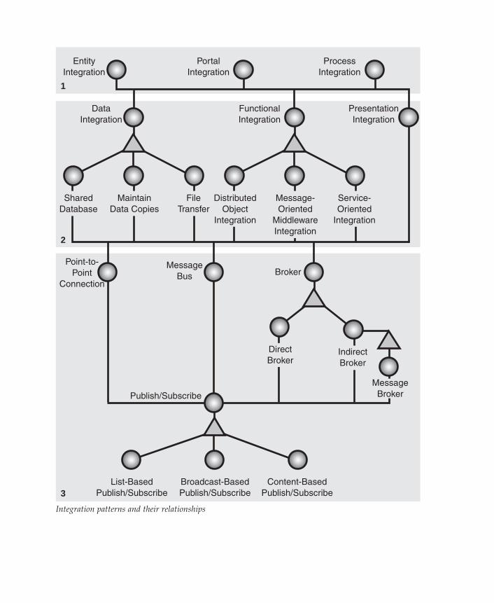
MaintainData Copies
DataIntegration
FileTransfer
Point-to-Point
Connection
MessageBus Broker
DistributedObject
Integration
Message-Oriented
MiddlewareIntegration
FunctionalIntegration
Service-Oriented
Integration
PresentationIntegration
EntityIntegration
1
2
3
PortalIntegration
ProcessIntegration
IndirectBroker
SharedDatabase
Broadcast-BasedPublish/Subscribe
Content-BasedPublish/Subscribe
List-BasedPublish/Subscribe
Direct Broker
Publish/Subscribe
MessageBroker
Integration patterns and their relationships